

Page 1

PCM-9340
ISA STPC Elite 133 SBC with
CPU/32MB SDRAM/VGA/LCD/
LAN/DOC/PC104
Users Manual
i
Page 2

Copyright
This document is copyrighted, © 2002, by EMAC, Inc. All rights
reserved. The original manufacturer reserves the right to make
improvements to the products described in this manual at any time without notice.
No part of this manual may be reproduced, copied, translated or transmitted in any form or by any means without the prior written permission of
the original manufacturer. Information provided in this manual is
intended to be accurate and reliable. However, the original manufacturer
assumes no responsibility for its use, nor for any infringements upon the
rights of third parties that may result from such use.
Acknowledgements
Award is a trademark of Award Software International, Inc.
VIA is a trademark of VIA Technologies, Inc.
IBM, PC/AT, PS/2 and VGA are trademarks of International Business
Machines Corporation.
Intel and Pentium are trademarks of Intel Corporation.
Microsoft Windows® is a registered trademark of Microsoft Corp.
RTL is a trademark of Realtek Semi-Conductor Co., Ltd.
ESS is a trademark of ESS Technology, Inc.
UMC is a trademark of United Microelectronics Corporation.
SMI is a trademark of Silicon Motion, Inc.
Creative is a trademark of Creative Technology LTD.
All other product names or trademarks are properties of their respective
owners.
For more information on this and other EMAC products, please visit
our website at: http://www.emacinc.com
For technical support and service, please visit our support website at:
This manual is for the PCM-9340 3.5" Biscuit SBC.
PCM-9340 User’s Manual ii
http://www.emacinc.com/technical_support.htm
Page 3

Packing List
Before you begin installing your card, please make sure that the following
materials have been shipped:
• 1 PCM-9340 all-in-one single board computer
• 1 startup manual
• 1 CD-ROM or disk for utilities, drivers, and manual
(in PDF format)
• 1 3.5" IDE flat cable P/N: (1701440504)
• 1 keyboard/mouse cable P/N: (1700060202)
• 1 secondary serial port cable P/N: (1701140201)
• 1 parallel cable P/N: (1700260250)
• 1 floppy cable P/N: (1701340603)
• 1 COM3/COM4 cable P/N: (1701200220)
• 1 Mini Jumper package (10 PCS) P/N: (9689000002)
If any of these items are missing or damaged, contact your distributor or
sales representative immediately.
The PCM-9340 Series Model Comparison Table
CPU 32MB
Memory
PCM-9340F-0CA1 vv v v
PCM-9340V-0CA1 vv v
PCM-9340N-0CA1 vv v
VGA/LCD Ethernet
iii
Page 4

PCM-9340 User’s Manual iv
Page 5

Table of Contents
Contents
Chapter 1 General Information ........................................1
1.1 Introduction ....................................................................... 2
1.2 Features ............................................................................. 3
1.3 Specifications .................................................................... 4
1.3.1 Standard SBC functions.................................................. 4
1.3.2 Flat Panel/VGA Interface ............................................... 4
1.3.3 Ethernet Interface (PCM-9340F and PCM-9340N)........ 5
1.3.4 Audio Interface (optional) .............................................. 5
1.3.5 Mechanical and Environmental ...................................... 5
1.3.6 Solid state disk ................................................................ 5
1.4 Board layout: dimensions.................................................. 6
Figure 1.1:Board layout: dimensions.............................. 6
Chapter 2 Connecting Peripherals ...................................7
2.1 Jumpers.............................................................................. 8
2.1.1 Jumper Locations ............................................................ 8
Figure 2.1:Jumper Locations .......................................... 8
2.1.2 Jumper Functions............................................................ 9
2.1.3 Setting Jumpers............................................................... 9
2.2 COM2 Select (JP2).......................................................... 10
2.3 Watchdog Timer Action (JP3) ........................................ 10
2.4 DOC© 2000 Address Setting (JP4) ................................ 11
2.5 Clear CMOS (JP5) .......................................................... 12
2.6 Audio Amp Power Select (JP7) ...................................... 12
2.7 Connectors....................................................................... 13
2.7.1 Connector Locations ..................................................... 13
Figure 2.2:Connector Locations ................................... 13
2.7.2 Connector Functions ..................................................... 14
2.8 Making Connections ....................................................... 15
2.9 CPU Fan power supply connector (CN1) ....................... 15
2.10 Serial ports (CN2, CN3, CN4) ........................................ 15
2.10.1 COM3/COM4 RS-232 port (CN2) ............................... 15
2.10.2 COM2 RS-232/422/485 selection (CN3) ..................... 16
2.10.3 COM1 RS-232 port (CN4) ........................................... 16
2.10.4 Share IRQ ..................................................................... 16
2.11 PC/104 connectors (CN5) .............................................. 16
2.12 Ethernet Connections (CN6, LED1, LED2).................... 16
2.12.1 100Base-T RJ-45 connector (CN6) .............................. 17
2.12.2 Network boot ................................................................ 17
2.12.3 Ethernet LED and HDD/power LEDs .......................... 17
2.13 Keyboard and PS/2 mouse connector (CN7) .................. 17
v
Page 6

2.14 IR connector (CN8) ......................................................... 18
2.15 Enhanced IDE HDD Connector (CN9) ........................... 18
2.16 VGA interface connections (CN10, CN15, CN19)......... 18
2.16.1 CRT display connector (CN10) .................................... 18
2.16.2 Extension flat panel connector (CN15) ........................ 19
2.16.3 Flat panel display connector (CN19)............................ 19
2.17 Audio interfaces (CN11, CN17) (optional)..................... 19
2.17.1 Audio connector (CN11) .............................................. 19
2.17.2 CD audio input connector (CN17)................................ 19
2.17.3 Audio power source setting (JP7)................................. 19
2.18 ATX power (CN13, CN16, CN22) ................................. 21
Figure 2.3:Wiring for ATX feature power.................... 21
2.18.1 ATX feature connector (CN13) .................................... 21
2.18.2 Board Main Power (CN16)........................................... 21
2.18.3 ATX soft power switch (CN22).................................... 21
2.19 FDD connector (CN14)................................................... 22
2.20 Parallel port connector (CN18) ....................................... 22
2.21 General Purpose Input Output (CN20)............................ 22
Chapter 3 Award BIOS Setup.........................................23
3.1 System test and initialization........................................... 24
3.1.1 System configuration verification................................. 24
3.2 Award BIOS setup .......................................................... 25
3.2.1 Entering setup .............................................................. 25
Figure 3.1:BIOS setup program initial screen .............. 25
3.2.2 Standard CMOS Features setup.................................... 26
Figure 3.2:CMOS Features setup.................................. 26
3.2.3 Advanced BIOS Features setup .................................... 27
Figure 3.3:Advanced BIOS Features setup................... 27
3.2.4 Advanced Chipset Features setup ................................. 28
Figure 3.4:Advanced Chipset Features setup ............... 28
3.2.5 Integrated Peripherals ................................................... 29
Figure 3.5:Integrated Peripherals.................................. 29
3.2.6 Power Management Setup ............................................ 30
Figure 3.6:Power Management Setup........................... 30
3.2.7 PnP/PCI Configurations................................................ 31
Figure 3.7:PnP/PCI Configurations .............................. 31
3.2.8 Load Optimized Defaults.............................................. 32
Figure 3.8:Load BIOS defaults screen.......................... 32
3.2.9 Set Password ................................................................. 32
Figure 3.9:Set Password ............................................... 34
3.2.10 Save & Exit Setup......................................................... 35
Figure 3.10:Save and Exit Setup................................... 35
3.2.11 Exit Without Saving...................................................... 36
Figure 3.11:Exit without Saving................................... 36
vi
Page 7

Table of Contents
Chapter 4 SVGA Setup ....................................................37
4.1 Introduction ..................................................................... 38
4.1.1 Chipset .......................................................................... 38
4.1.2 Display memory............................................................ 38
4.2 Installation of the SVGA Driver ..................................... 38
4.2.1 Installation for Windows 95 ......................................... 39
4.2.2 Installation for Windows 98 ......................................... 44
4.2.3 Installation for Windows NT ........................................ 49
4.3 Further Information ......................................................... 54
Chapter 5 PCI Bus Ethernet Interface...........................55
5.1 Introduction ..................................................................... 56
5.2 Ethernet Driver Installation ............................................. 56
5.2.1 Installation for Windows 95 ......................................... 57
5.2.2 Installation for Windows 98 ......................................... 62
5.2.3 Installation for Windows NT ........................................ 69
5.3 Further information ......................................................... 71
Chapter 6 Audio Setup.....................................................73
6.1 Introduction ..................................................................... 74
6.2 Audio Driver Installation ................................................ 74
6.2.1 Installation for Windows 95/98/NT .............................. 75
Appendix A Programming the Watchdog Timer .............77
A.1 Supported Input Timing Modes ...................................... 78
Appendix B Installing PC/104 Modules ............................81
B.1 Installing PC/104 Modules.............................................. 82
Figure B.1:PC/104 module mounting diagram............. 83
Figure B.2:PC/104 module dimensions (mm) (±0.1) ... 84
Appendix C Pin Assignments .............................................85
C.1 CPU fan power connector (CN1) .................................... 86
C.2 COM 3, COM 4 connector (CN2)................................... 86
C.3 COM 2 connector (CN3)................................................. 87
C.4 COM 1 RS-232 connector (CN4).................................... 87
C.5 PC/104 Connector (CN5) ................................................ 88
C.6 Ethernet 10/100Base-T Connector (CN6)....................... 90
C.7 Keyboard and PS/2 Mouse Connector (CN7) ................. 90
C.8 IR Connector (CN8) ........................................................ 91
C.9 IDE Hard Drive Connector (CN9) .................................. 92
C.10 CRT Display Connector (CN10)..................................... 93
C.11 Audio Connector (optional) (CN11) ............................... 93
C.12 LCD Inverter Backlight Connector (CN12).................... 94
C.13 ATX Power Feature Connector (CN13).......................... 94
C.14 Floppy Disk Drive Connector (CN14) ............................ 95
vii
Page 8

C.15 Extended Flat Panel Display Connector (CN15.............. 96
C.16 Main Power Connector (CN16) ...................................... 96
C.17 CD audio connector (CN17) ........................................... 96
C.18 Parallel Port Connector (CN18) ...................................... 97
C.19 Flat Panel Connector (CN19).......................................... 98
C.20 General Purpose Input Output (CN20)............................ 99
C.21 Auxiliary power connector (CN21)................................. 99
C.22 ATX Power Button (CN22) ............................................ 99
C.23 Reset Button Connector (SW1)..................................... 100
Appendix D System Assignments .....................................101
D.1 System I/O Ports............................................................ 102
D.2 DMA channel assignments............................................ 103
D.3 Interrupt assignments .................................................... 104
D.4 1st MB memory map..................................................... 105
D.5 DMA channel assignments............................................ 105
D.6 Interrupt assignments .................................................... 106
Appendix E Mechanical Drawings...................................107
E.1 Mechanical Drawings.................................................... 108
viii
Page 9

Chapter 1 General Info rmation
1
CHAPTER
General Information
This chapter gives background
information on the PCM-9340.
Sections include:
• Introduction
• Features
• Specifications
• Board layout and dimensions
1 Chapter 1 General Information
Page 10

Chapter 1 Introduction
1.1 Introduction
The PCM-9340 is the ultimate cost-effective solution for limited-space
applications. It offers all the functions of an AT-compatible industrial
computer on a single board. The PCM-9340 comes with an embedded
high-performance STPC Elite 133 processor and 32MB SDRAM on
board. For maximum performance, the PCM-9340 also supports one
optional SODIMM socket that can accept up to 64 MB memory.
On-board features include an Ethernet interface, a socket for DOC®
2000, Enhanced IDE interface, one parallel port, four serial ports (three
RS-232s, and one RS-232/422/485) with DB-9 connectors, and a miniDIN PS/2 keyboard/mouse interface, and an optional audio function. An
SVGA/LCD display controller (LCD, and CRT displays) allows LCD
screen resolutions up to 1024 x 768 @ 64K colors and CRT resolutions
up to 1280 x 1024 @ 256 colors.
The PCM-9340 complies with the “Green Function” standard and supports three types of power saving features: Normal, Doze and Sleep
modes.
The display type configuration is done through software. A single Flash
chip holds the system BIOS and the VGA BIOS. This minimizes the
number of chips and eases configuration. You can change the display
BIOS simply by programming the Flash chip.
If you need any additional functions, the PCM-9340 has a PC/104 connector for future upgrades.
PCM-9340 User’s Manual 2
Page 11

1.2 Features
• On-board Low power STMicroelectronics STPC Elite 133 processor
(fanless)
• On-board 32 MB SDRAM
• On-board VGA/LCD display controller and supports DSTN/TFT LCD
• 62-level watchdog timer, jumperless on-line setup supported
• Supports wake-up on LAN, ring-on by Modem
• SSD supports DiskOnChip® 2000
• Supports CMOS data backup functions
• PC/104 connector supports face-up installation
• Optional audio function
3 Chapter 1 General Information
Page 12

1.3 Specifications
1.3.1 Standard SBC functions
• CPU: Embedded STMicroelectronics STPC Elite 133 MHz processor
(provides fanless operation)
• BIOS: 2 Mbit Flash BIOS,
-Supports Plug & Play, APM
-Supports Ethernet Boot ROM
-Supports boot from CD-ROM
-Supports boot from LS-120 ZIP™ Drive
-Optional Customer icon can be supplied
• Chipset: STPC Elite 133
• System memory: Onboard 32MB SDRAM,
and one optional SDRAM SODIMM max. 64MB socket
• PCI IDE interface: One Enhanced IDE interface. Supports 2 IDE
devices PIO mode 3,4 with bus mastering up to 14 MB/sec.
• Floppy disk drive interface: Supports up to two FDDs (360 KB/1.2
MB/720 KB/1.44 MB/2.88 MB)
• Parallel port: One parallel port, supports EPP/ECP
• IR port: One 115 Kbps IrDA compliant serial infrared
• Serial ports: 4 serial ports:: COMs1,3,4: RS-232; COM2:
RS-232/422/485; COM2 RS-485 supports Autoflow contro l
• Watchdog timer: 62-level timer interval, setup by software or jumperless selection, generates system reset or IRQ11.
1.3.2 Flat Panel/VGA Interface
(PCM-9340F and PCM-9340V)
• Chipset: SMI LynxEM+ 712
• Display memory: 2 MB on the chip
• Display type: Simultaneous support for CRT and 36-bit TFT LCD
display (supports 3.3 V LCD) Supports 3, 9,12,18, 24, 36-bit TFT and
16 or 24-bit DSTN Panel
• CRT display modes:
1280 x 1024@16bpp (60Hz)
1024 x 768@16bpp (85Hz)
800 x 600 @24bpp(85Hz)
PCM-9340 User’s Manual 4
Page 13

• Panel display modes:
1280 x 1024@16bpp (60Hz)
1024 x 768@16bpp (60Hz)
800 x 600 @24bpp(60Hz)
1.3.3 Ethernet Interface (PCM-9340F and PCM-9340N)
• Chipset: RTL 8139C
• Ethernet interface: PCI 10/100 Mbps Ethernet. IEEE 802.3 u protocol compatible
• Connection: On-board RJ-45 connector
• Wake on LAN (via ATX power supply)
• I/O address switchless setting
• Built-in boot ROM
1.3.4 Audio Interface (optional)
• Chipset: Avance Logic ALS4000
• PCI Interface, Mic in, Line in, CD Audio in, Line out, speaker out
1.3.5 Mechanical and Environmental
• Dimensions (L x W): 145 mm x 102 mm (5.9" x 4.2")
• Power supply voltage: +5 V (4.75 V ~ 5.25 V)
• Power requirements: Maximum: 5.0 V @ 2 A
Typical: +5.0 V @ 1.62 A
• Operating temperature: 0 ~ 60° C (32 ~ 140° F)
• Operating humidity: 0% ~ 90% Relative Humidity, non-condensing
• Weight: 0.23 Kg (0.5 lbs)
• Size: 185 mm x 122 mm
1.3.6 Solid state disk
• Provides support for one DOC® 2000.
5 Chapter 1 General Information
Page 14
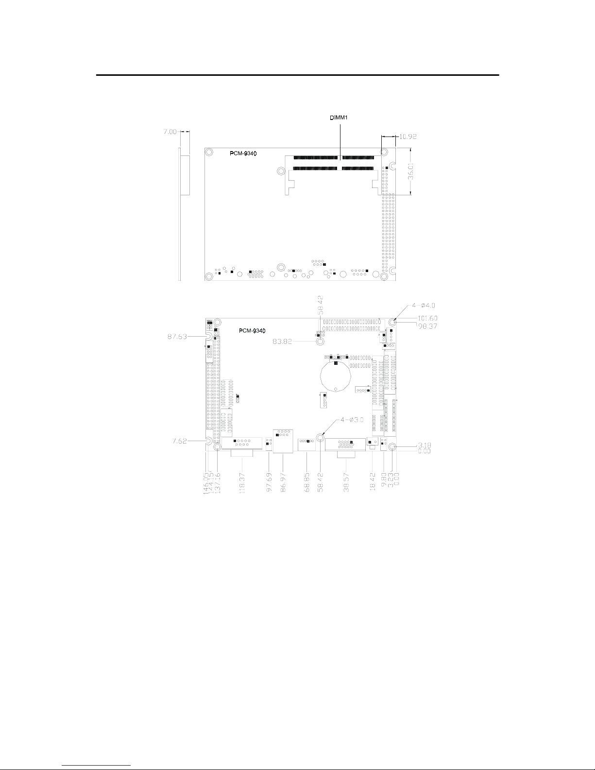
1.4 Board layout: dimensions
Figure 1.1: Board layout: dimensions
PCM-9340 User’s Manual 6
Page 15

Chapter 2 Connecting Peripherals
2
CHAPTER
Connecting Peripherals
This chapter tells how to connect
peripherals, switches, and indicators to the
PCM-9340 board. It also covers jumper
settings. You can access most of the connectors from the top of the board while it
is installed in the chassis. If you have a
number of cards installed, or your chassis
is very tight, you may need to partially
remove the card to make all the connections.
7 Chapter 2 Connecting Peripherals
Page 16
Chapter 2 Installation
2.1 Jumpers
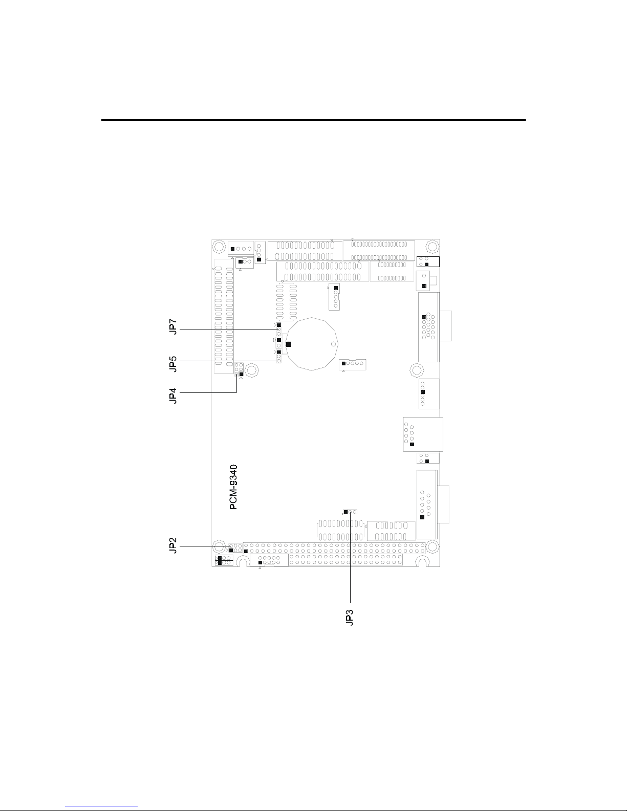
The PCM-9340 has a number of jumpers that allow you to configure your
system to suit your application.
2.1.1 Jumper Locations
PCM-9340 User’s Manual 8
Figure 2.1: Jumper Locations
Page 17
2.1.2 Jumper Functions
Table 2.1: Jumper Functions
Label Function
JP2 COM2 selector
JP3 Watchdog timer action
JP4 DOC® 2000 address setting
JP5 Clear CMOS
JP7 Audio power selector
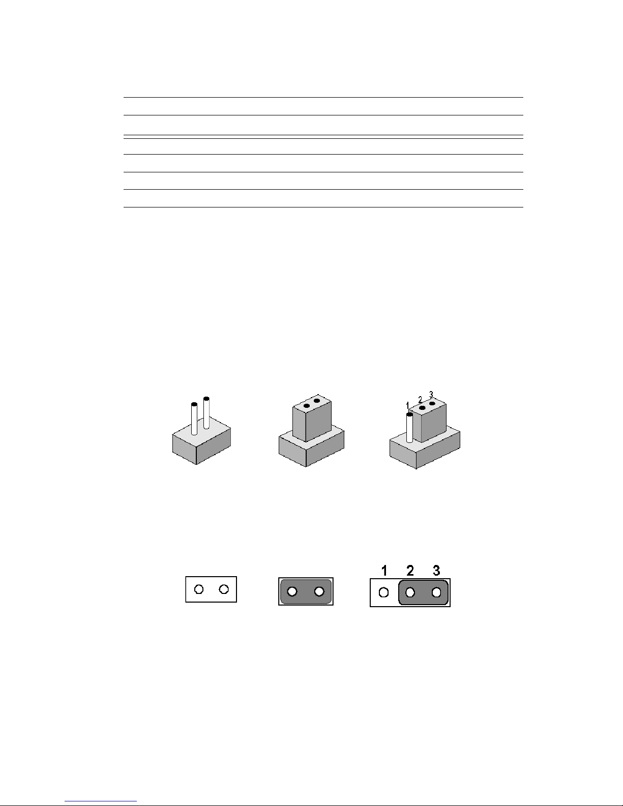
2.1.3 Setting Jumpers
You may configure your card to match the needs of your application by
setting jumpers. A jumper is a metal bridge used to close an electric circuit. It consists of two metal pins and a small metal clip (often protected
by a plastic cover) that slides over the pins to connect them. To “close” a
jumper, you connect the pins with the clip. To “open” a jumper, you
remove the clip. Sometimes a jumper will have three pins, labeled 1, 2
and 3. In this case you would connect either pins 1 and 2, or 2 and 3.
open closed closed 2-3
The jumper settings are schematically depicted in this manual as follows:.
open closed 2-3 closed
A pair of needle-nose pliers may be helpful when working with jumpers.
If you have any doubts about the best hardware configuration for your
application, contact your local distributor or sales representative before
you make any changes.
9 Chapter 2 Connecting Peripherals
Page 18
2.2 COM2 Select (JP2)
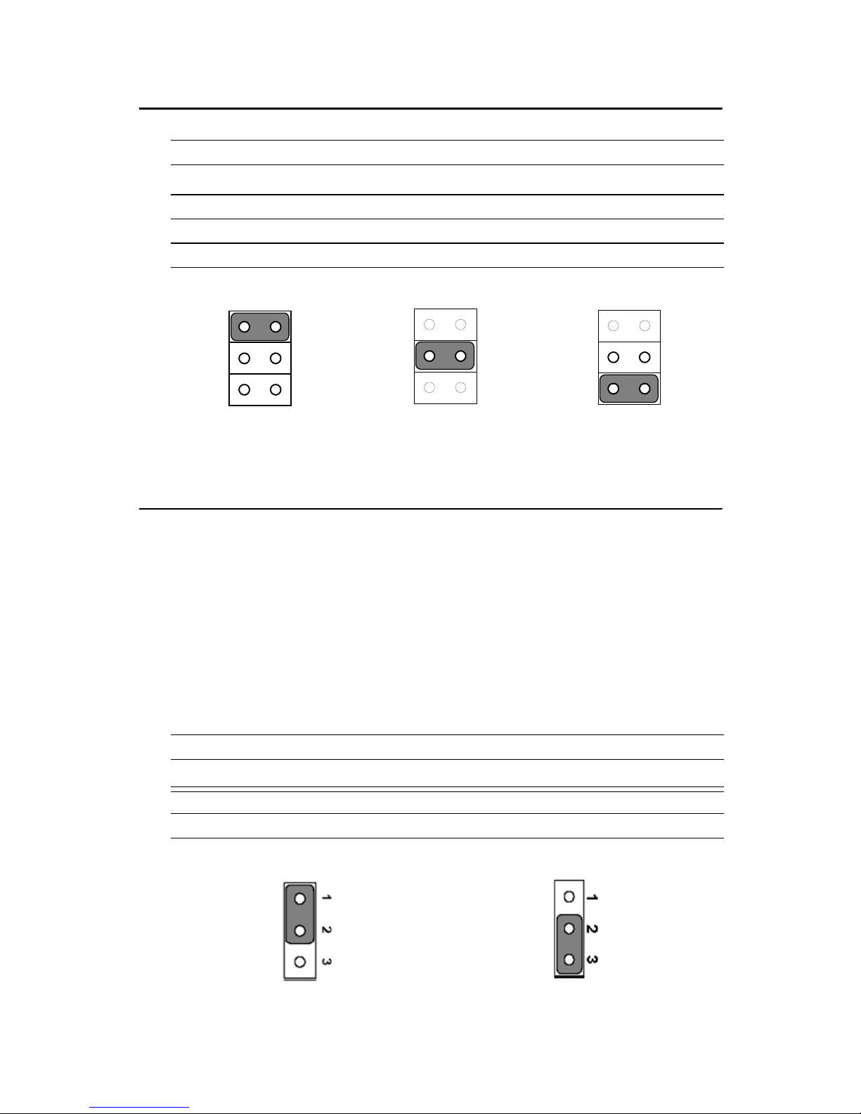
Table 2.2: JP2: COM2 RS-232/422/485 Select
Pins Function
1-2* COM2/RS-232*
3-4 COM2/RS-422
5-6 COM2/RS-485
* default setting
135
246
135
246
135
RS-232* RS-422 RS-485
2.3 Watchdog Timer Action (JP3)
An on-board watchdog timer reduces the chance of disruptions which
EMP (electro-magnetic pulse) interference can cause. This is an invaluable protective device for standalone or unmanned applications. Setup
involves one jumper setting and running the control software (refer to
Appendix A).
When the watchdog timer activates (CPU processing has come to a halt),
it can either reset the system or generate an interrupt on IRQ11. This
choice for watchdog timer action is set via JP3 as shown below:
246
Table 2.3: JP3: Watchdog Timer
Pins Function
1-2* Reset
2-3 IRQ 11
* default setting
reset* IRQ 11
PCM-9340 User’s Manual 10
Page 19
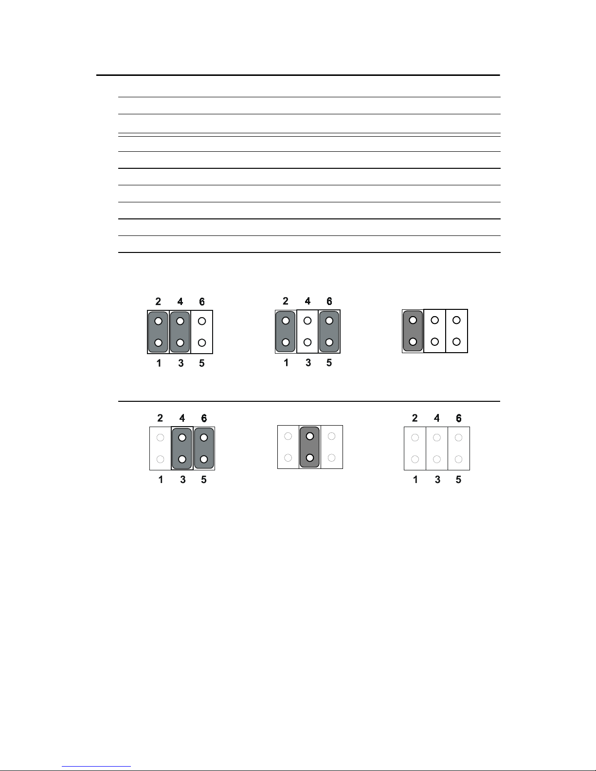
2.4 DOC© 2000 Address Setting (JP4)
Table 2.4: JP4: DOC® 2000 address setting
Pins Address
1-2 3-4 5-6
closed closed open CC000 ~ CDFFF
*closed open closed D0000 ~ D1FFF
closed open open D4000~ D5FFF
open closed closed D8000 ~ D9FFF
open closed open DC000 ~ DDFFF
open open open OFF
*default setting
246
135
CC000 ~ CDFFF D0000 ~ D1FFF* D4000~ D5FFF
246
135
D8000 ~ D9FFF DC000 ~ DDFFF OFF
11 Chapter 2 Connecting Peripherals
Page 20
2.5 Clear CMOS (JP5)
Warning!
To avoid damaging the computer, always turn
off the power supply before clearing the
CMOS. Before turning the power supply back
on, return the jumper to “3.0 V Battery On.”
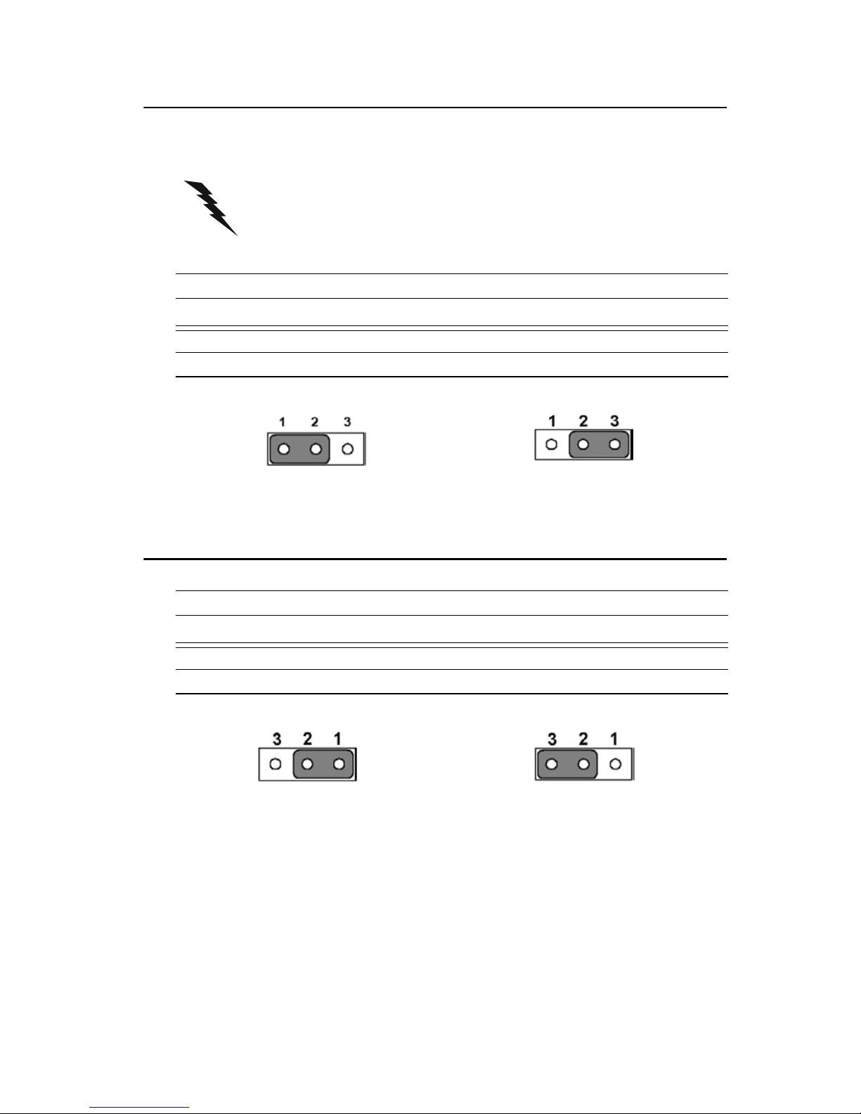
Table 2.5: JP5: Clear CMOS
Pins Function
1-2 clear CMOS
2-3* 3.0 V battery on
* default setting
clear CMOS 3.0 V battery on*
2.6 Audio Amp Power Select (JP7)
Table 2.6: JP7: Audio amplifier power select
Pins Function
1-2* +5V (main power)
2-3 Regulated +5V
* default setting
+5V (main power)* Regulated +5V
PCM-9340 User’s Manual 12
Page 21
2.7 Connectors
Connectors on the board link it to external devices such as hard disk
drives, a keyboard or expansion bus connectors.
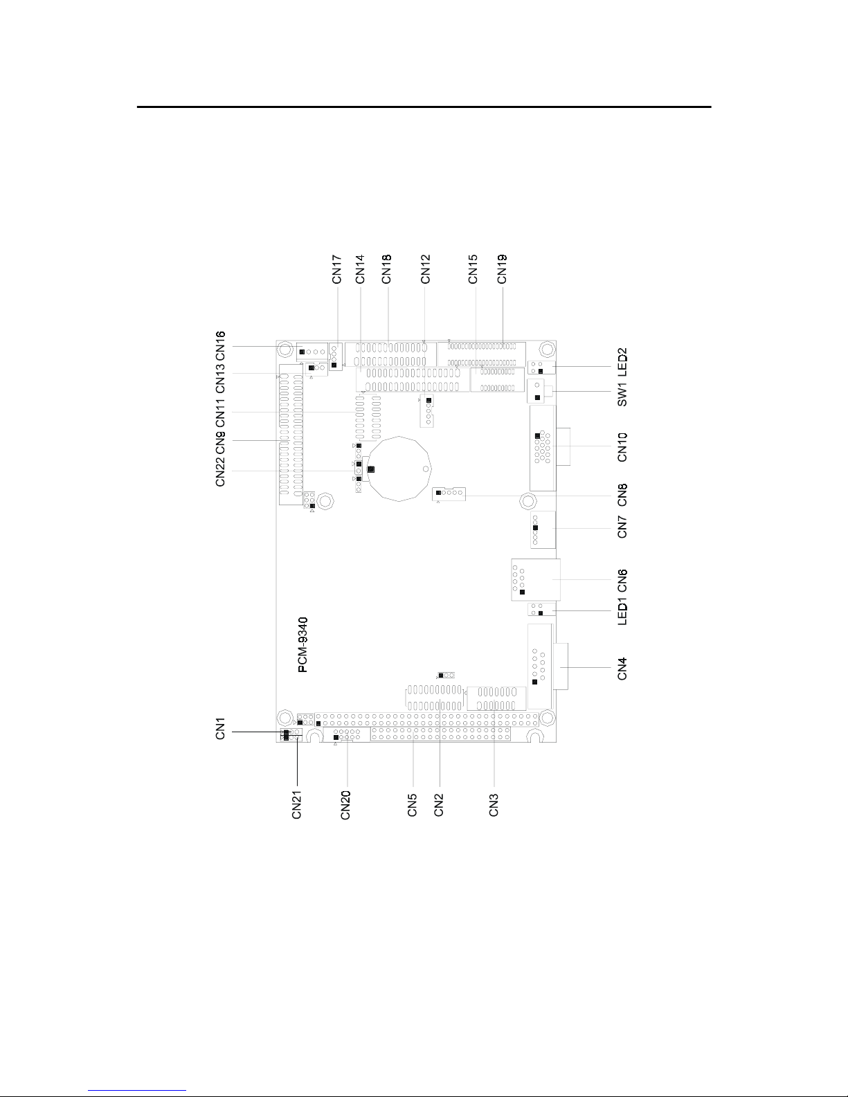
2.7.1 Connector Locations
Figure 2.2: Connector Locations
13 Chapter 2 Connecting Peripherals
Page 22

2.7.2 Connector Functions
Table 2.7: Connectors
Label Function
CN1 CPU fan connector
CN2 COM3/COM4 connector
CN3 COM2 connector
CN4 COM1 connector
CN5 PC/104 connector
CN6 Ethernet connector
CN7 PS/2 keyboard and PS/2 mouse
CN8 IR connector (infrared)
CN9 Hard disk connector
CN10 CRT display connector
CN11 Audio connector (optional)
CN12 Backlight connector
CN13 ATX feature connector
CN14 Floppy disk connector
CN15 Ext. flat panel connector
CN16 Power connector (+5 V, +12 V)
CN17 CD Audio
CN18 Parallel port connector
CN19 Flat panel connector
CN20 GPIO connector
CN21 Aux Power connector (-5 V, -12 V)
CN22 ATX power button
LED1 Ethernet LED
LED2 Power and HDD activity LED
SW1 Reset switch
PCM-9340 User’s Manual 14
Page 23
2.8 Making Connections
The following sections tell how to make each connection. In most cases,
you will simply need to connect a standard cable. All of the connector pin
assignments are shown in Appendix C.
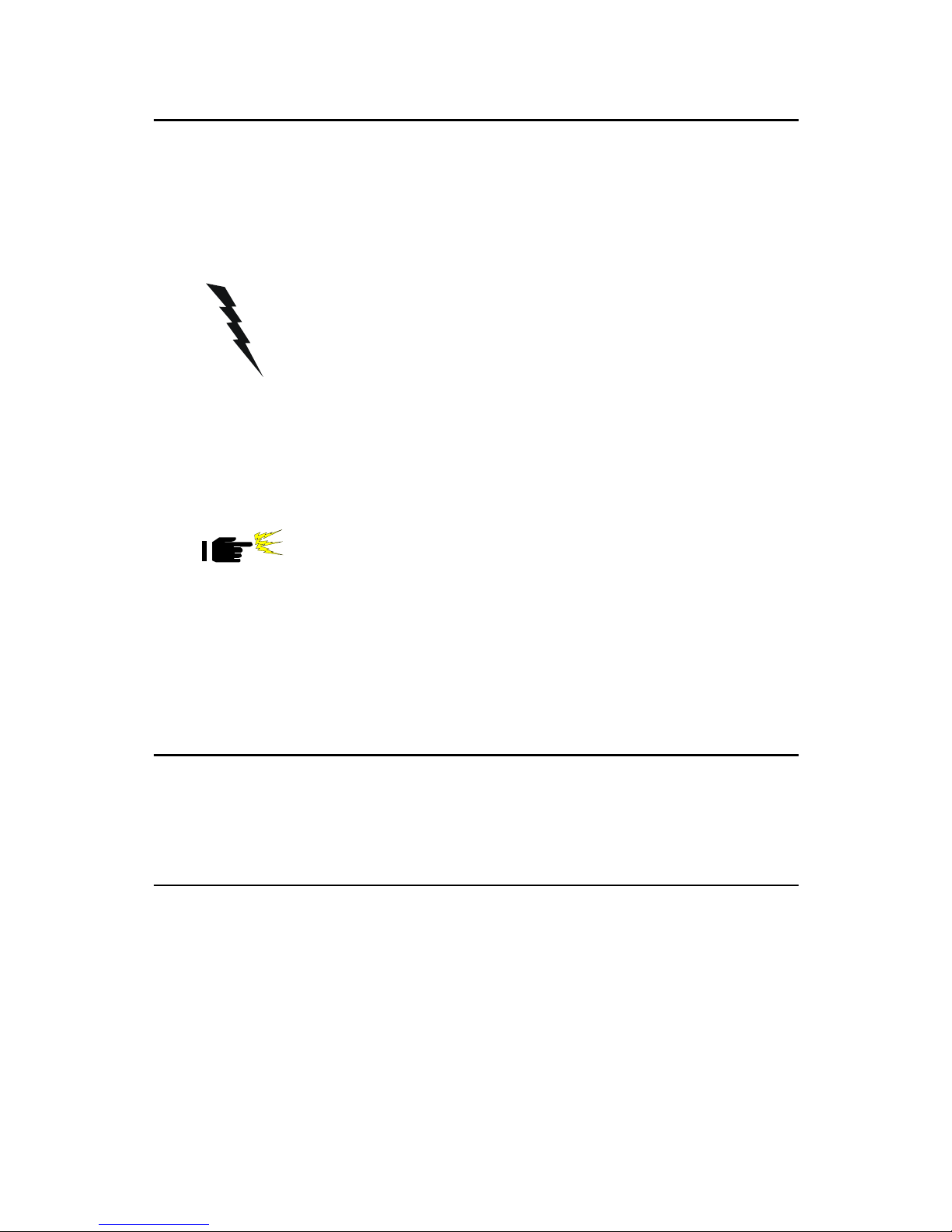
Warning!
Caution!
Always completely disconnect the power cord
from your chassis whenever you are working
on it. Do not make connections while the power
is on. Sensitive electronic components can be
damaged by a sudden rush of power. Only
experienced electronics personnel should open
the PC chassis.
Always ground yourself to remove any static
charge before touching the CPU card. Modern
electronic devices are very sensitive to static
electric charges. Use a grounding wrist strap at
all times. Place all electronic components on a
static-dissipative surface or in a static-shielded
bag when they are not in the chassis. This is
especially important where the ambient air is
very dry.
2.9 CPU Fan power supply connector (CN1)
Provides power supply to CPU cooling fan. Only present when +5 V and
+12 V power is supplied to the board.
2.10 Serial ports (CN2, CN3, CN4)
The PCM-9340 offers four serial ports: three RS-232 (COM 1, 3, 4) and
one RS-232/422/485 (COM 2). These ports allow you to connect to any
serial device (a mouse, a printer, etc.) or to a communication network.
2.10.1 COM3/COM4 RS-232 port (CN2)
The COM3/COM4 series port, consists of 20 pin dual-in-line, male
header.
15 Chapter 2 Connecting Peripherals
Page 24

2.10.2 COM2 RS-232/422/485 selection (CN3)
This secondary port between CN2 and CN4 consists of a 14-pin, dual-inline, male header, and can be configured, via JP2 (q.v.), to operate in RS-
232, RS-422, or RS-485 mode.
The IRQs and address ranges for the COM ports are fixed. However, if
you wish to disable a port or change these parameters later, you can do
this in the system BIOS setup.
2.10.3 COM1 RS-232 port (CN4)
This serial port connector is the 9-pin D-SUB connector toward the left
side.
2.10.4 Share IRQ
The IRQ and the address range for COM1, 2, 3, 4 default are fixed. However, if you wish to disable the port or change these parameters later, you
can do this in the system BIOS setup. The table below shows the settings
for the PCM-9340's serial ports.
Table 2.8: Serial port default settings
Port Address range Interrupt
COM1 3F8 ~ 3FF IRQ4
COM2 2F8~2FF IRQ3
COM3 3E8~3EF IRQ10
COM4 2E8~2EF IRQ5
COM1-4 can share one IRQ that can be selected in BIOS setup under
Windows 98 and Windows NT. Choices are: IRQ3, IRQ4, IRQ5 or
IRQ10.
2.11 PC/104 connectors (CN5)
The PCM-9340 is equipped with a 16-bit ISA signal PC/104 connector
for future expansion. See Appendix B for details.
2.12 Ethernet Connections (CN6, LED1, LED2)
The PCM-9340 is equipped with a high performance 32-bit PCI Ethernet
interface which is fully compliant with IEEE 802.3u 10/100 Mbps
CSMA/CD standards. It is supported by all major network operating systems.
The Ethernet medium can be configured via the RSET8139.EXE program
included on the utility disk. (See Chapter 5 for detailed information.)
PCM-9340 User’s Manual 16
Page 25

2.12.1 100Base-T RJ-45 connector (CN6)
100Base-T connections are made via the on-board RJ-45 connector.
2.12.2 Network boot
The network boot feature is built into the BIOS. It can be enabled or disabled in the chipset setup of the CMOS configuration. Refer to Chapter 3,
“Award BIOS Setup,” for more information.
2.12.3 Ethernet LED and HDD/power LEDs (LED1, LED2)
Ethernet LED (LED1)
Table 2.9: Ethernet LED setup
LED Setting
Green lamp Tx
Yellow lamp Link
LED 1 should be set so that when the cable is connected, the yellow lamp
is activated; and when data is transmitted, the green lamp is activated.
Note polarity on LEDs.
Power and HDD LED (LED2)
Table 2.10: HDD/power LED setup
LED Setting
Green lamp Power
Yellow lamp HDD
LED 2 should be set so when the HDD is accessed, the yellow lamp is
activated; and when the power is on, the green lamp is activated. Polarity
is important on LED lamps.
2.13 Keyboard and PS/2 mouse connector (CN7)
The PCM-9340 board provides a keyboard connector. A 6-pin mini-DIN
connector (CN7) on the card mounting bracket supports singleboard computer applications. The card comes with an adapter to convert from the 6pin mini-DIN connector to a standard DIN connector and to a PS/2 mouse
connector.
17 Chapter 2 Connecting Peripherals
Page 26

2.14 IR connector (CN8)
This connector supports the optional wireless infrared transmitting and
receiving module. This module mounts on the system case. You must
configure the setting through BIOS setup.
2.15 Enhanced IDE HDD Connector (CN9)
You can attach two IDE (Integrated Device Electronics) drives to the
PCM-9340 internal controller. The PCM-9340 SBC card has an EIDE
connector, CN9.
Wire number 1 on the cable is red or blue, and the other wires are gray.
Connect one end to connector CN9 on the PCM-9340. Make sure that the
red (or blue) wire corresponds to pin 1 on the connector. See Figure 2-1,
where pin 1 is indicated with a triangle or a solid square.
Unlike floppy drives, IDE hard drives can connect in either position on
the cable. If you install two drives, you will need to set one as the master
and one as the slave. You do this by setting the jumpers on the drives. If
you use just one drive, you should set it as the master. See the documentation that came with your drive for more information.
Connect the first hard drive to the free end of the cable. Wire 1 on the
cable should also connect to pin 1 on the hard drive connector, which
should be labeled on the drive circuit board. Check the documentation
that came with the drive for more information. If you are using a second
drive, connect it to the remaining connector on the same cable.
2.16 VGA interface connections (CN10, CN15, CN19)
The PCM-9340’s PCI SVGA interface can drive conventional CRT displays and is capable of driving a wide range of flat panel displays, including passive and active LCD displays. The board has two connectors to
support these displays, one for standard CRT VGA monitors and one for
flat panel displays.
2.16.1 CRT display connector (CN10)
CN10 is a 16-pin, dual-inline header used for conventional CRT displays.
A simple one-to-one adapter can be used to match CN10 to a standard 15pin D-SUB connector commonly used for VGA.
Pin assignments for CRT display connector CN18 are detailed in Appendix C.
PCM-9340 User’s Manual 18
Page 27

2.16.2 Extension flat panel connector (CN15)
CN15 consists of a 20-pin connector which is Hirose’s product no.
DF13A-20DP-1.25V. The PCM-9340 supports a 36-bit LCD panel which
must be connected to both the CN19 (40-pin) and the CN15 (20-pin). The
pin assignments for both CN19 and the CN15 can be found in Appendix
C.
2.16.3 Flat panel display connector (CN19)
CN19 consists of a 40-pin connector which can support a 24-bit LCD
panel. It is Hirose’s product no. DF13A-40DP-1.25 V
The PCM-9340 provides a bias control signal on CN19 that can be used
to control the LCD bias voltage. It is recommended that the LCD bias
voltage not be applied to the panel until the logic supply voltage (+5 V or
+3.3 V) and panel video signals are stable. Under normal operation, the
control signal (ENAVEE) is active high. When the PCM-9340’s power is
applied, the control signal is low until just after the relevant flat panel signals are present.
2.17 Audio interfaces (CN11, CN17) (optional)
The PCM-9340 is equipped with a high-quality audio interface, which
provides 16-bit CD-quality recording and playback as well as OPL3 compatible FM music. It is supported by all major operating systems.
2.17.1 Audio connector (CN11)
The PCM-9340 provides all major audio signals on a 16-pin flat-cable
connector, CN11. These audio signals include Microphone in (mono),
Line in (stereo), Line out (stereo), and Speaker out (stereo). If you use traditional telephone jack connectors for these audio signals, you will need
an adapter cable.
2.17.2 CD audio input connector (CN17)
Any CD-ROM drive can provide analog audio signal output when used as
a music CD player. The CN17 on PCM-9340 is a connector to input CD
audio signals into the audio controller. The audio cable of your CD-ROM
drive will be used to connect to CN17.
2.17.3 Audio power source setting (JP7)
The PCM-9340 is designed to work with a single +5 V power supply. The
audio interface can also function normally under single +5V power supply, but most audio controllers require an independent power source generated from a +12 V power supply. The independent power source avoids
the noise from the other digital circuits. The PCM-9340’s audio interface
19 Chapter 2 Connecting Peripherals
Page 28

can accept +12 V power to provide improved quality audio. This is done
via JP7.)
Table 2.11: JP7: Audio Power Source Setting
Pins Function
1-2* +5V (main power)
2-3 Regulated +5V
+5V (main power)* Regulated +5V
* default setting
Configuration of the audio interface may be done entirely via the software utility. You do not have to set any jumpers if you don’t want to.
Refer to Chapter 6 for audio setup details.
PCM-9340 User’s Manual 20
Page 29
2.18 ATX power (CN13, CN16, CN22)
The PCM-9340 supports an advanced soft power switch function, if an
ATX power supply is used.
Important
Make sure that the ATX power supply can take
at least a 10 mA load on the 5 V standby lead
(5VSB). If not, you may have difficulty powering on your system.
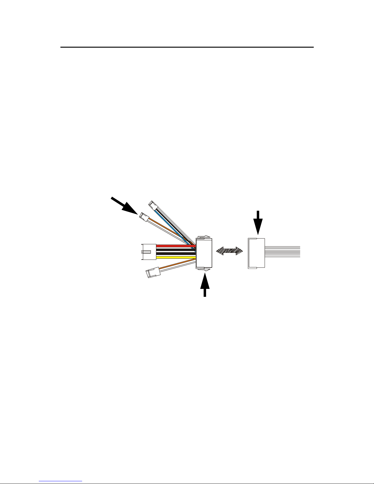
To enable the soft power switch function, get the specially designed ATXto-EBX power cable (PCM-9340 optional item, part no. 1703200201).
to CN13 ATX
feature connector
from ATX
power supply
to onboard power
connector CN16
1703200201
20-pin
female connector
Figure 2.3: Wiring for ATX feature power
Connect the ATX female end to the ATX connector from the power supply.
2.18.1 ATX feature connector (CN13)
Connect the tiny 2-wire plug to CN13 (ATX feature connector).
2.18.2 Board Main Power (CN16)
Connect the 4-wire plug to CN16.
2.18.3 ATX soft power switch (CN22)
Connect the power on/off button to CN22. (A momentary button switch
should be used.)
21 Chapter 2 Connecting Peripherals
Page 30

2.19 FDD connector (CN14)
You can attach up to two floppy disk drives to the PCM-9340's onboard
controller. You can use any combination of 5.25" (360 KB/1.2 MB) and/
or 3.5" (720 KB/1.44/2.88 MB) drives.
The card comes with a 34-pin daisy-chain drive connector cable. On one
end of the cable is a 34-pin flat-cable connector. On the other end are two
sets of floppy disk drive connectors. Each set consists of a 34-pin flatcable connector (usually used for 3.5" drives) and a printed-circuit-board
connector (usually used for 5.25" drives). You can use only one connector
in each set. The set on the end (after the twist in the cable) connects to the
A: floppy. The set in the middle connects to the B: floppy.
2.20 Parallel port connector (CN18)
The parallel port is designated as LPT1, and is normally used to connect
the CPU card to a printer. The PCM-9340 includes an on-board parallel
port, accessed through a 26-pin flat-cable connector, CN18. The card
comes with an adapter cable which lets you use a traditional DB-25 connector. The cable has a 26-pin connector on one end and a DB-25 connector on the other, mounted on a retaining bracket. The bracket installs at
the end of an empty slot in your chassis, giving you access to the connector.
To install the bracket, find an empty slot in your chassis. Unscrew the
plate that covers the end of the slot. Screw in the bracket in place of the
plate. Next, attach the flat-cable connector to CN18 on the CPU card.
Wire 1 of the cable is red or blue, and the other wires are gray. Make sure
that wire 1 corresponds to pin 1 of CN18. Pin 1 is on the right side of
CN18.
2.21 General Purpose Input Output (CN20)
The PCM-9340 supports 8-bit GPIO through CN20. The 8 digital in- and
out-puts can be programmed to read or control devices, with input or output defined. The default setting is 4 bits input and 4 bits output.
PCM-9340 User’s Manual 22
Page 31

Chapter 4 Award BIOS Setup
3
CHAPTER
Award BIOS Setup
This chapter describes how to set BIOS
configuration data.
23 Chapter 3 Award BIOS Setup
Page 32

Chapter 3 Award BIOS Setup
3.1 System test and initialization
These routines test and initialize board hardware. If the routines encounter an error during the tests, you will either hear a few short beeps or see
an error message on the screen. There are two kinds of errors: fatal and
non-fatal. The system can usually continue the boot up sequence with
non-fatal errors. Non-fatal error messages usually appear on the screen
along with the following instruction:
press <F1> to RESUME
Write down the message and press the F1 key to continue the bootup
sequence.
3.1.1 System configuration verification
These routines check the current system configuration against the values
stored in the board’s CMOS memory. If they do not match, the program
outputs an error message. You will then need to run the BIOS setup program to set the configuration information in memory.
There are three situations in which you will need to change the CMOS
settings:
1. You are starting your system for the first time
2. You have changed the hardware attached to your system
3. The CMOS memory has lost power and the configuration informa-
tion has been erased.
The PCM-9340 Series' CMOS memory has an integral lithium battery
backup. The battery backup should last ten years in normal service, but
when it finally runs down, you will need to replace the complete unit.
PCM-9340 User’s Manual 24
Page 33
3.2 Award BIOS setup
Award’s BIOS ROM has a built-in Setup program that allows users to
modify the basic system configuration. This type of information is stored
in battery-backed CMOS RAM so that it retains the Setup information
when the power is turned off.
3.2.1 Entering setup
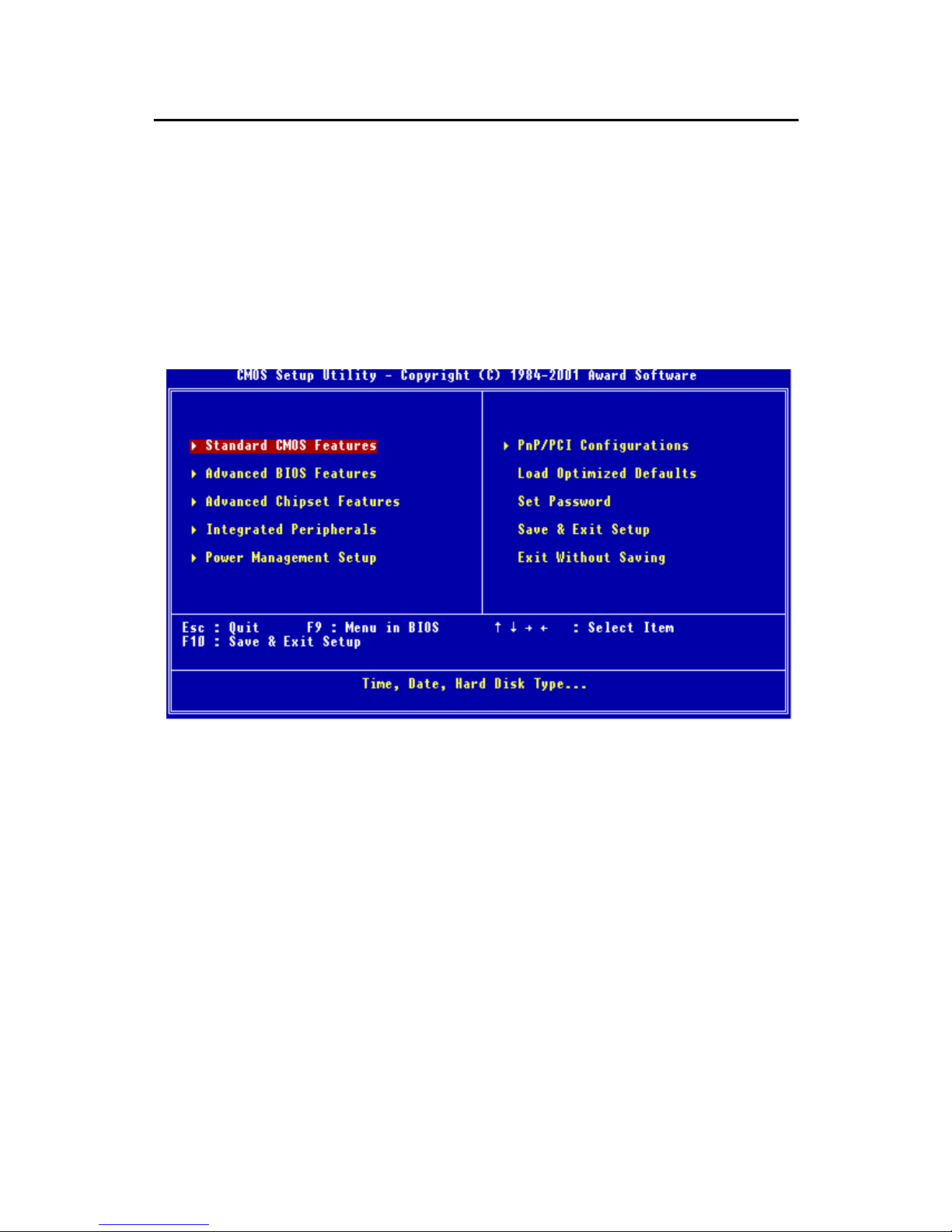
Power on the computer and press <Del> immediately. This will allow you
to enter Setup.
Figure 3.1: BIOS setup program initial screen
25 Chapter 3 Award BIOS Setup
Page 34
3.2.2 Standard CMOS Features setup
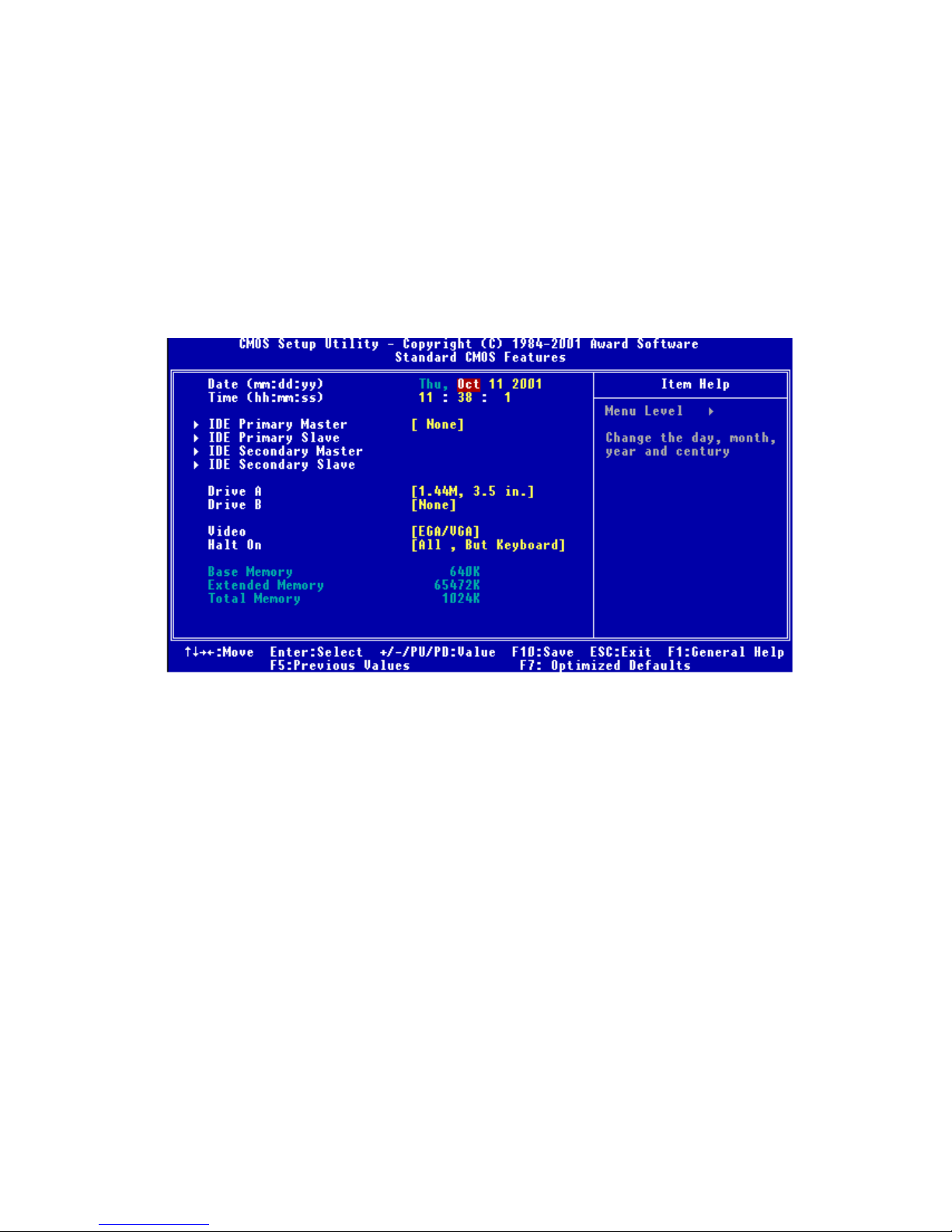
When you choose the Standard CMOS Features option from the Initial
Setup Screen menu, the screen shown below is displayed. This standard
Setup Menu allows users to configure system components such as date,
time, hard disk drive, floppy drive and display. Once a field is highlighted, on-line help information is displayed in the left bottom of the
Menu screen.
Figure 3.2: CMOS Features setup
PCM-9340 User’s Manual 26
Page 35
3.2.3 Advanced BIOS Features setup
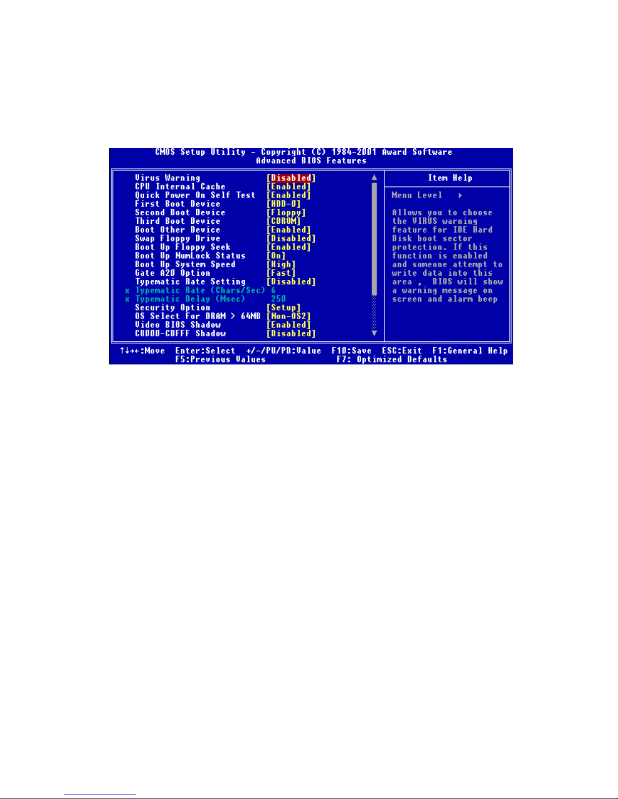
By choosing the Advanced BIOS Features Setup option from the Initial
Setup Screen menu, the screen below is displayed. This sample screen
contains the manufacturer’s default values for the PCM-9340 Series.
Figure 3.3: Advanced BIOS Features setup
27 Chapter 3 Award BIOS Setup
Page 36
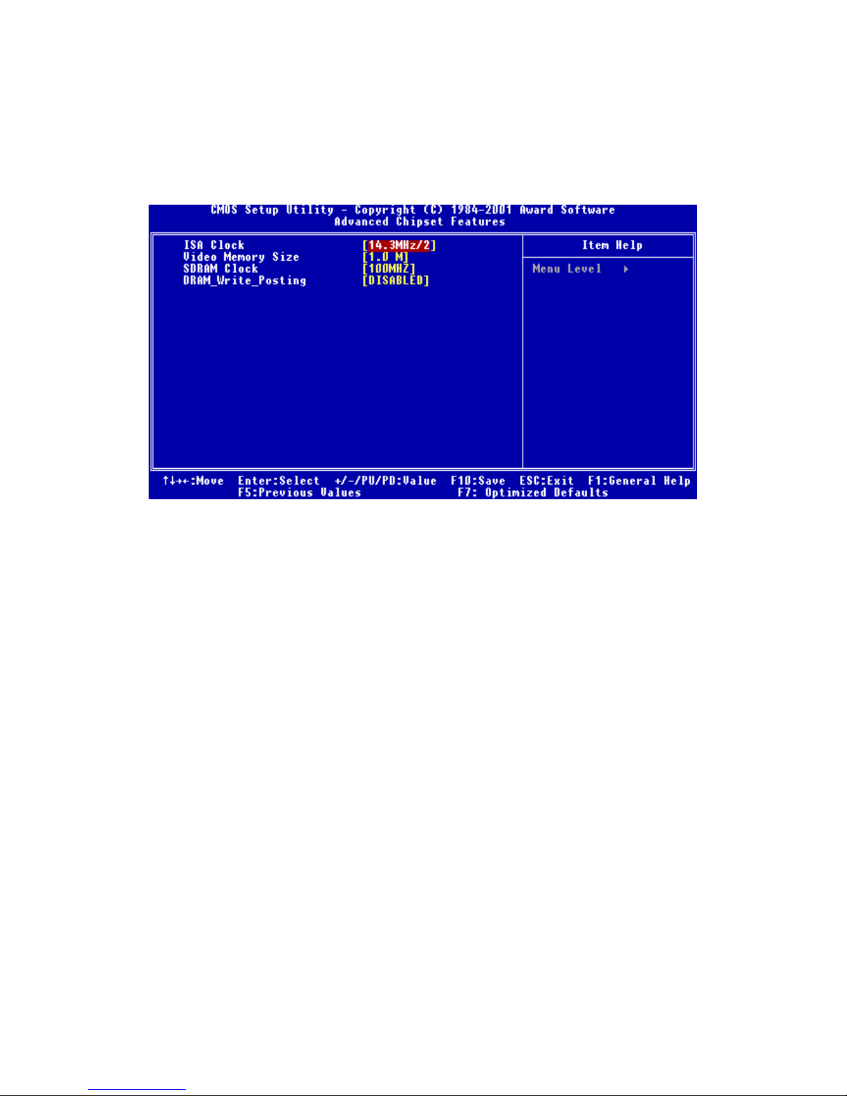
3.2.4 Advanced Chipset Features setup
By choosing the Advanced Chipset Features option from the Initial Setup
Screen menu, the screen below is displayed. This sample screen contains
the manufacturer’s default values for the PCM-9340 Series.
Figure 3.4: Advanced Chipset Features setup
PCM-9340 User’s Manual 28
Page 37
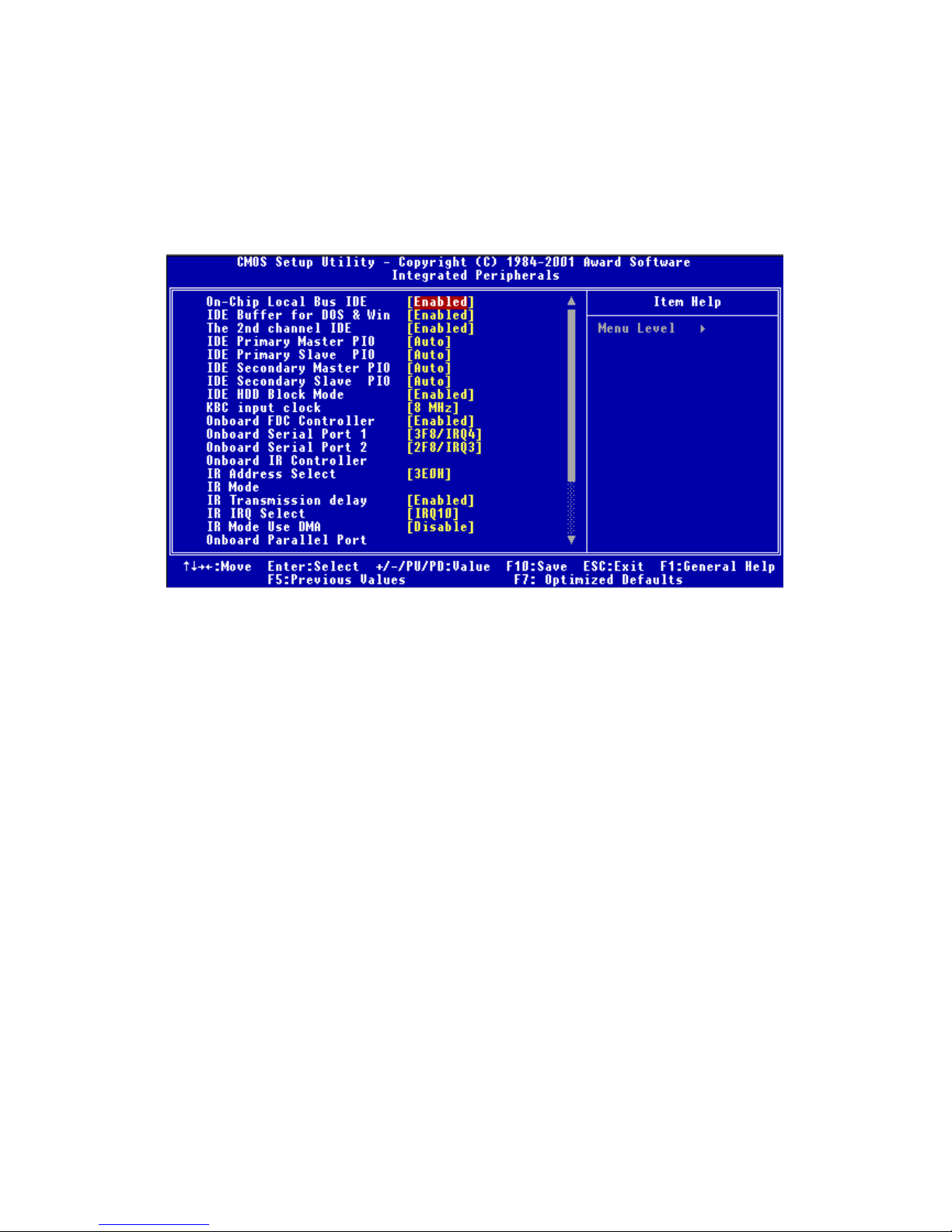
3.2.5 Integrated Peripherals
Choosing the Integrated Peripherals option from the Initial Setup Screen
menu should produce the screen below. Here we see the manufacturer’s
default values for the PCM-9340 Series. The PANEL TYPE by default
supports a 18-bit 640 x 480 TFT LCD panel display.
Figure 3.5: Integrated Peripherals
29 Chapter 3 Award BIOS Setup
Page 38
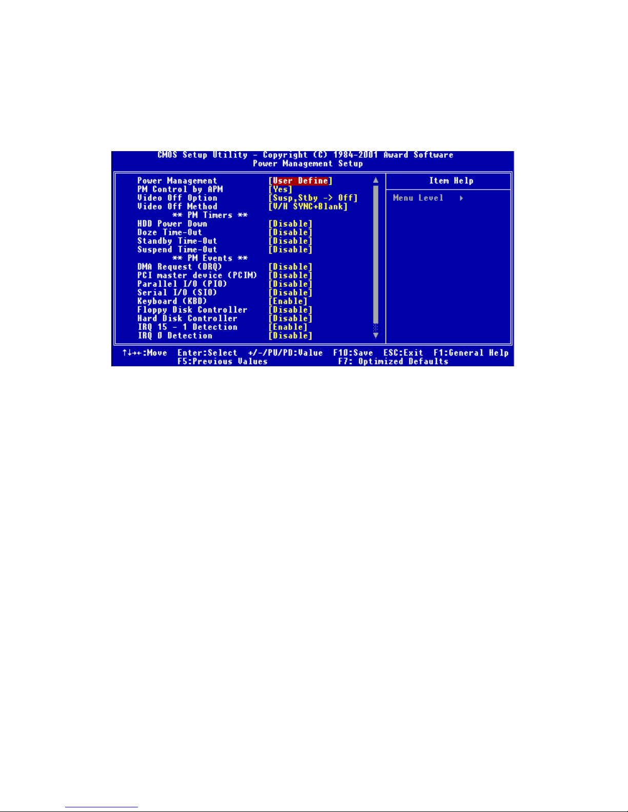
3.2.6 Power Management Setup
By choosing the Power Management Setup option from the Initial Setup
Screen menu, the screen below is displayed. This sample screen contains
the manufacturer’s default values for the PCM-9340 Series.
Figure 3.6: Power Management Setup
PCM-9340 User’s Manual 30
Page 39
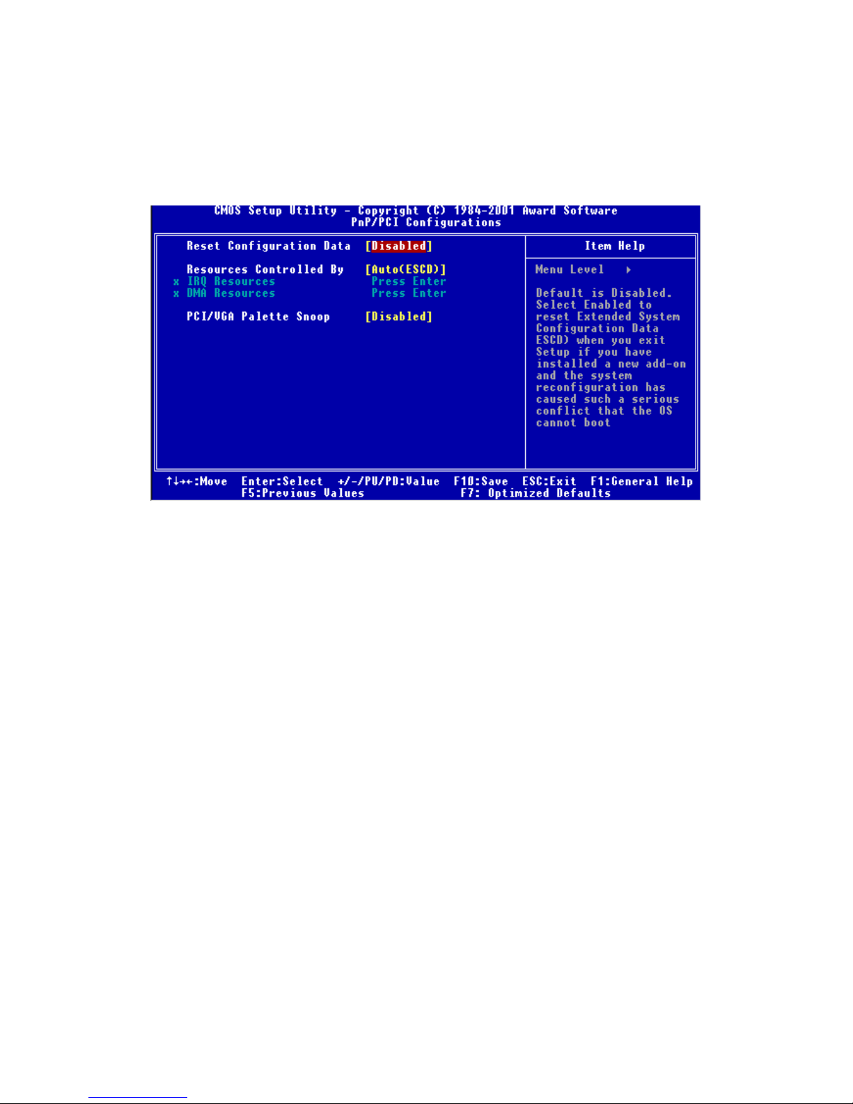
3.2.7 PnP/PCI Configurations
By choosing the PnP/PCI Configurations option from the Initial Setup
Screen menu, the screen below is displayed. This sample screen contains
the manufacturer’s default values for the PCM-9340 Series.
Figure 3.7: PnP/PCI Configurations
31 Chapter 3 Award BIOS Setup
Page 40
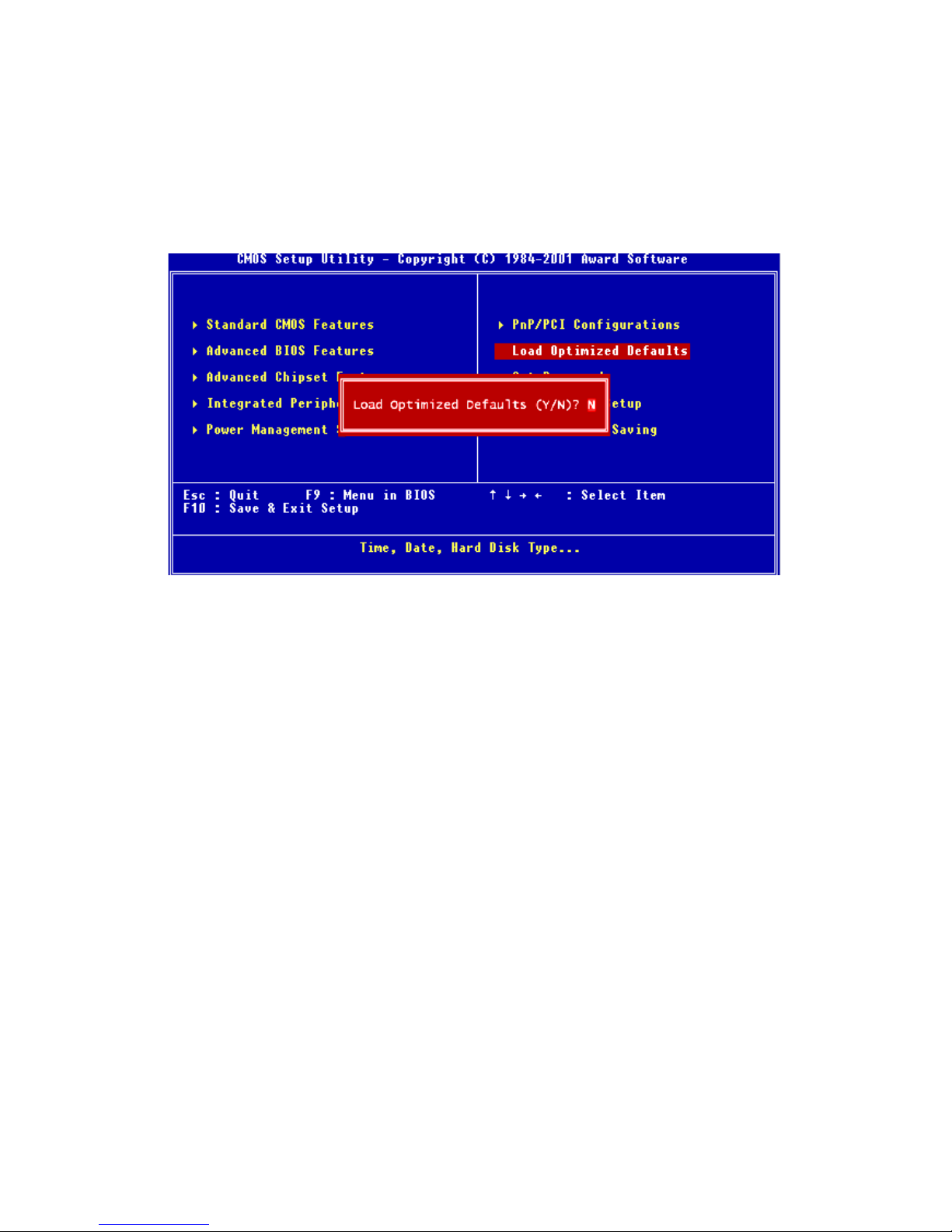
3.2.8 Load Optimized Defaults
Load Optimized Defaults loads the default system values directly from
ROM. If the stored record created by the Setup program should ever
become corrupted (and therefore unusable), these defaults will load automatically when you turn the PCM-9340 Series system on.
Figure 3.8: Load BIOS defaults screen
3.2.9 Set Password
Note To enable this feature, you should first go to the
Advanced BIOS Features menu, choose the Security
Option, and select either Setup or System, depending
on which aspect you want password protected. Setup
requires a password only to enter Setup. System
requires the password either to enter Setup or to boot
the system.
A password may be at most 8 characters long.
To Establish Password
1. Choose the Set Password option from the CMOS Setup Utility
main menu and press <Enter>.
2. When you see “Enter Password,” enter the desired password and
press <Enter>.
PCM-9340 User’s Manual 32
Page 41

3. At the “Confirm Password” prompt, retype the desired password,
then press <Enter>.
4. Select Save to CMOS and EXIT, type <Y>, then <Enter>.
To Change Password
1. Choose the Set Password option from the CMOS Setup Utility
main menu and press <Enter>.
2. When you see “Enter Password,” enter the existing password and
press <Enter>.
3. You will see “Confirm Password.” Type it again, and hit <Enter>.
4. Select Set Password again, and at the “Enter Password” prompt,
enter the new password and press <Enter>.
5. At the “Confirm Password” prompt, retype the new password, and
press <Enter>.
6. Select Save to CMOS and EXIT, type <Y>, then <Enter>.
33 Chapter 3 Award BIOS Setup
Page 42
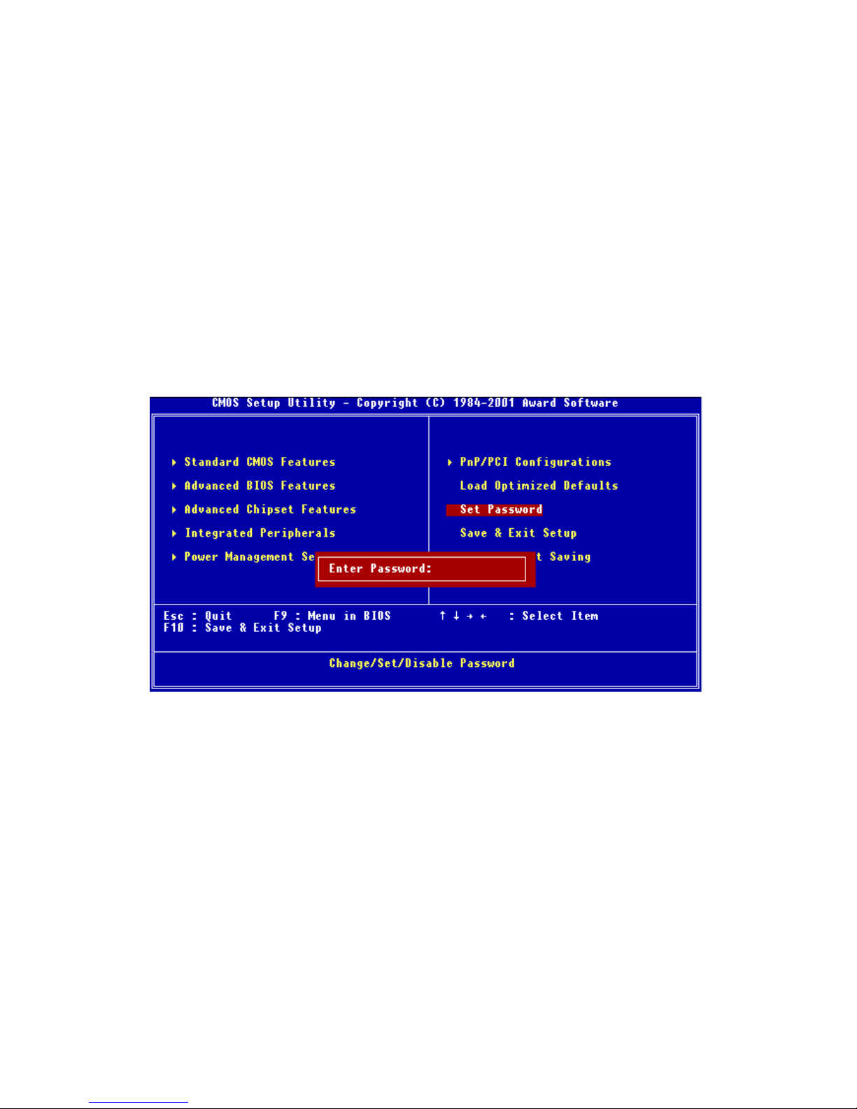
To Disable Password
1. Choose the Set Password option from the CMOS Setup Utility
main menu and press <Enter>.
2. When you see “Enter Password,” enter the existing password and
press <Enter>.
3. You will see “Confirm Password.” Type it again, and hit <Enter>.
4. Select Set Password again, and at the “Enter Password” prompt,
don’t enter anything; just press <Enter>.
5. At the “Confirm Password” prompt, again don’t type in anything;
just press <Enter>.
Select Save to CMOS and EXIT, type <Y>, then <Enter>.
PCM-9340 User’s Manual 34
Figure 3.9: Set Password
Page 43
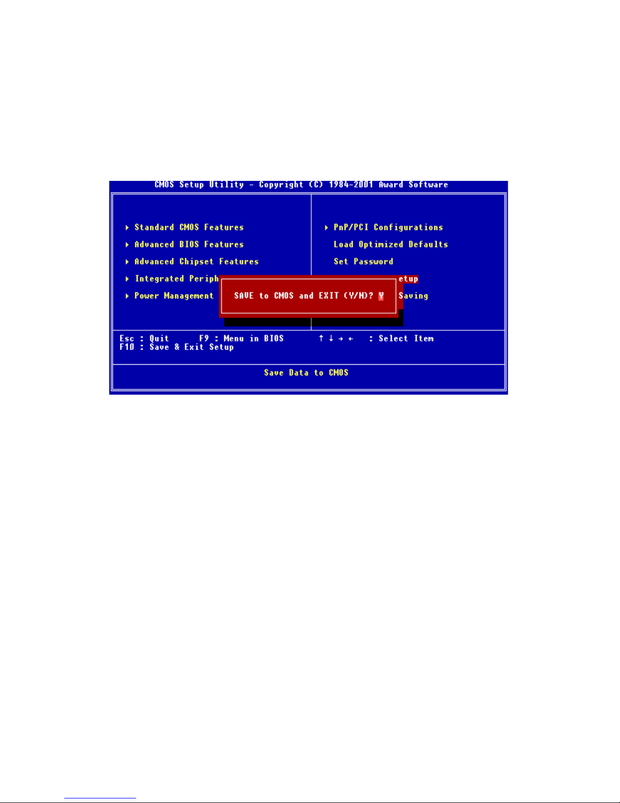
3.2.10 Save & Exit Setup
If you select this option and press <Y> then <Enter>, the values entered
in the setup utilities will be recorded in the chipset’s CMOS memory. The
microprocessor checks this every time you turn your system on and uses
the settings to configure the system. This record is required for the system
to operate.
Figure 3.10: Save and Exit Setup
35 Chapter 3 Award BIOS Setup
Page 44
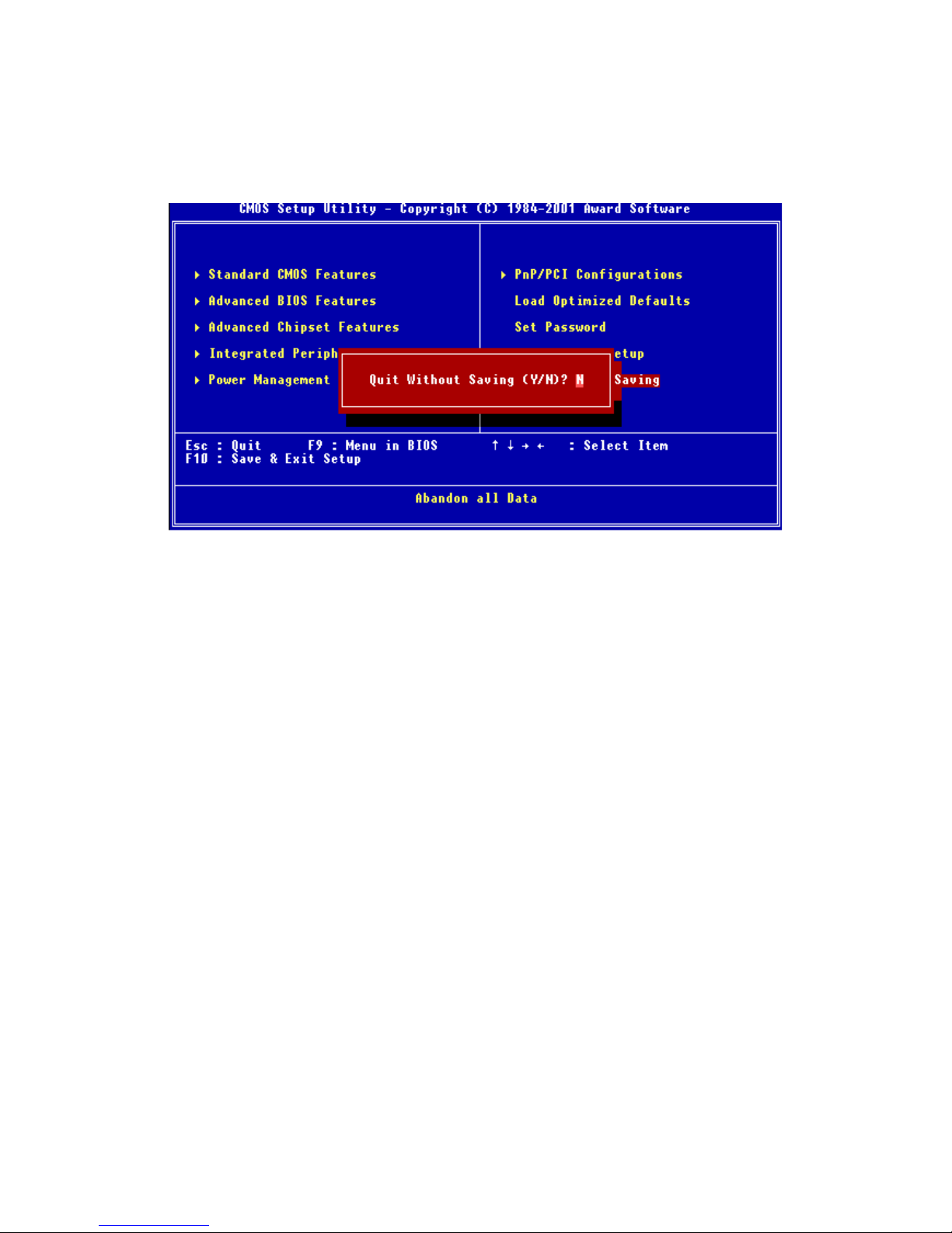
3.2.11 Exit Without Saving
Selecting this option and pressing <Enter> lets you exit the Setup program without recording any new values or changing old ones.
Figure 3.11: Exit without Saving
PCM-9340 User’s Manual 36
Page 45

SVGA Setup
• Introduction
• Installation of SVGA drivers
-for Windows 95/98/NT
Chapter 5 PCI VGA Setup
4
CHAPTER
37 Chapter 4 SVGA Setup
Page 46

Chapter 4 PCI SVGA Setup
4.1 Introduction
The PCM-9340 has an on-board LCD/VGA interface. The specifications
and features are described as follows:
4.1.1 Chipset
The PCM-9340 uses a SMI LynxEM+ 712G chipset for its SVGA controller. It supports many popular 18-bit LCD displays and conventional
analog CRT monitors. The VGA BIOS supports LCD. In addition, it also
supports interlaced and non-interlaced analog monitors (color and monochrome VGA) in high-resolution modes while maintaining complete IBM
VGA compatibility. Digital monitors (i.e. MDA, CGA, and EGA) are
NOT supported. Multiple frequency (multisync) monitors are handled as
if they were analog monitors.
4.1.2 Display memory
With 2MB shared memory, the VGA controller can drive CRT displays or
color panel displays with resolutions up to 1280 x 1024 at 256 colors.
4.2 Installation of the SVGA Driver
Complete the following steps to install the SVGA driver.
Notes:
1. The windows illustrations in this chapter are
intended as examples only. Please follow the
listed steps, and pay attention to the instructions which appear on your screen.
2. For convenience, the CD-ROM drive is designated as "D" throughout this chapter.
3. When you are using a CRT display, please
make sure that your resolution settings (in the
BIOS setup) are the same as your VGA resolution settings (in Windows). Otherwise your display may behave strangely.
PCM-9340 User’s Manual 38
Page 47
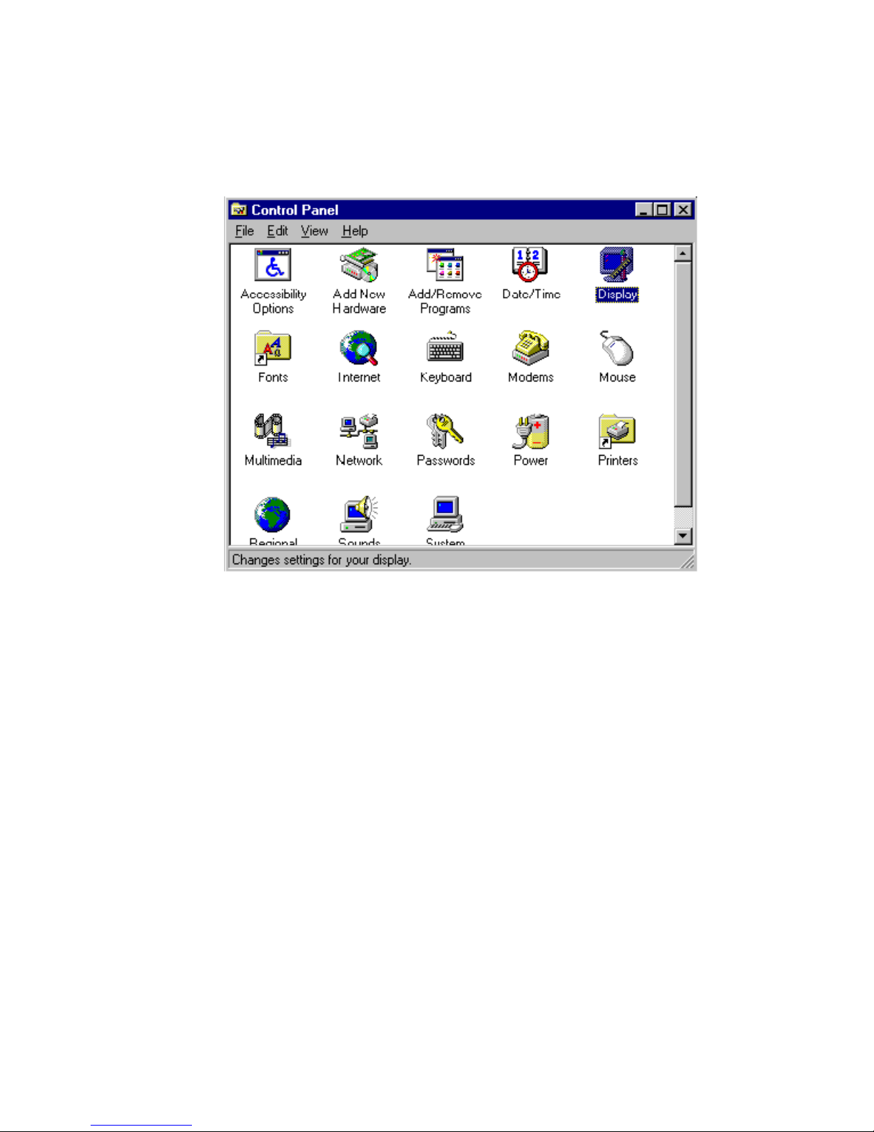
4.2.1 Installation for Windows 95
1. In the Windows 95 Main screen, click on "Start," select "Settings,"
then "Control Panel." Double click the "Display" icon.
39 Chapter 4 SVGA Setup
Page 48

2. Select the "Settings" tab, then click the "Advanced Properties" but-
ton.
PCM-9340 User’s Manual 40
Page 49
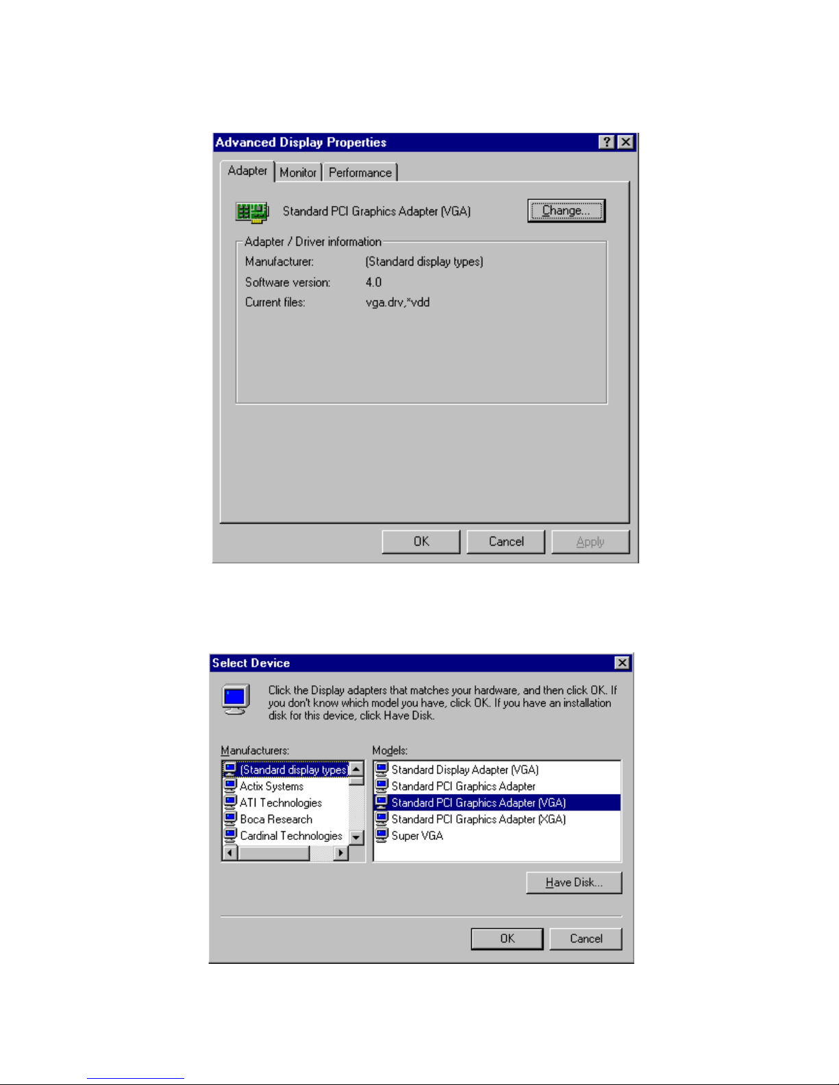
3. Choose the "Adapter" tab, then press the "Change..." button.
4. Press the "Have Disk" button.
41 Chapter 4 SVGA Setup
Page 50
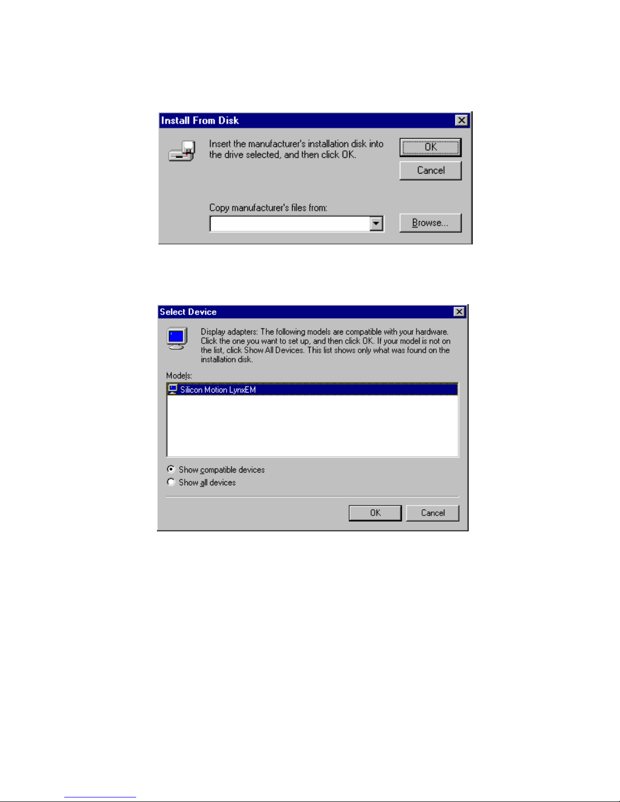
5. Direct the path to the SMI VGA driver in the CD and click "OK" to
install the driver.
D:\VGA\WIN95
6. Select the highlighted item, and click the "OK" button.
PCM-9340 User’s Manual 42
Page 51
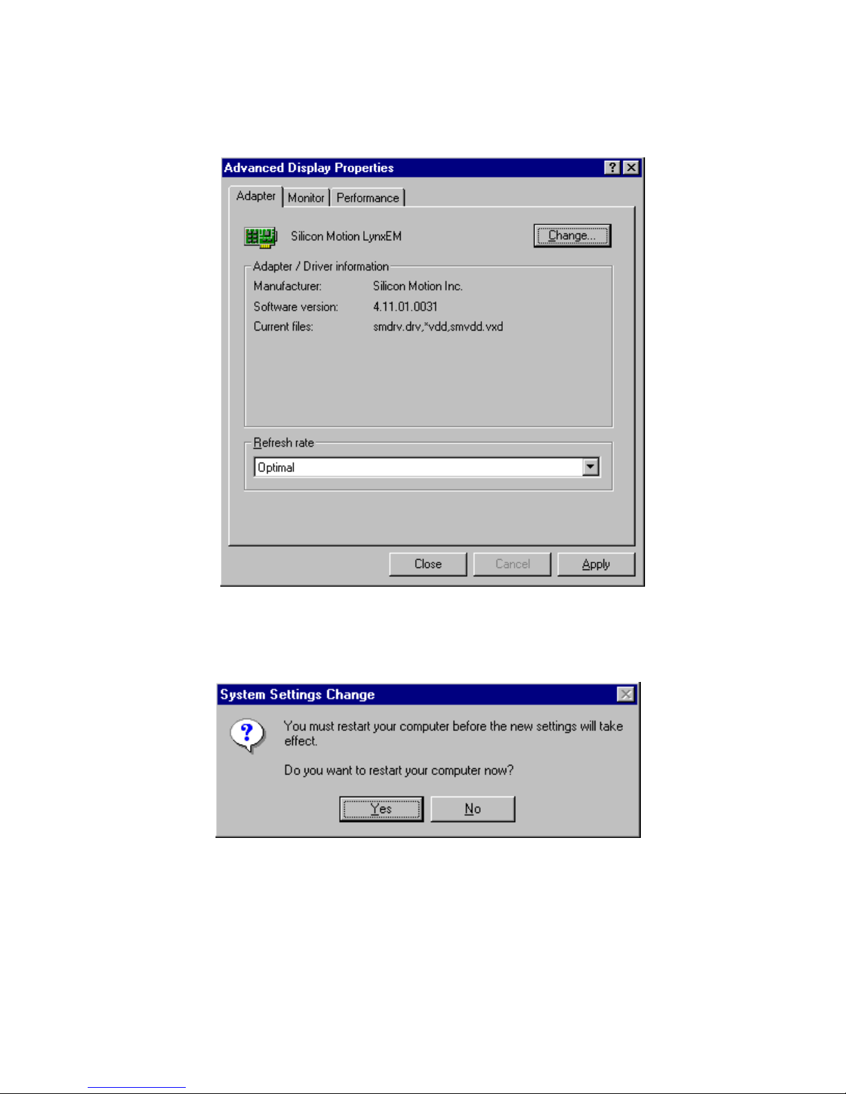
7. “Silicon Motion LynxEM” appears under the adapter tab. Click the
“Apply” button, then the “OK” button.
8. Press “Yes” to reboot.
43 Chapter 4 SVGA Setup
Page 52
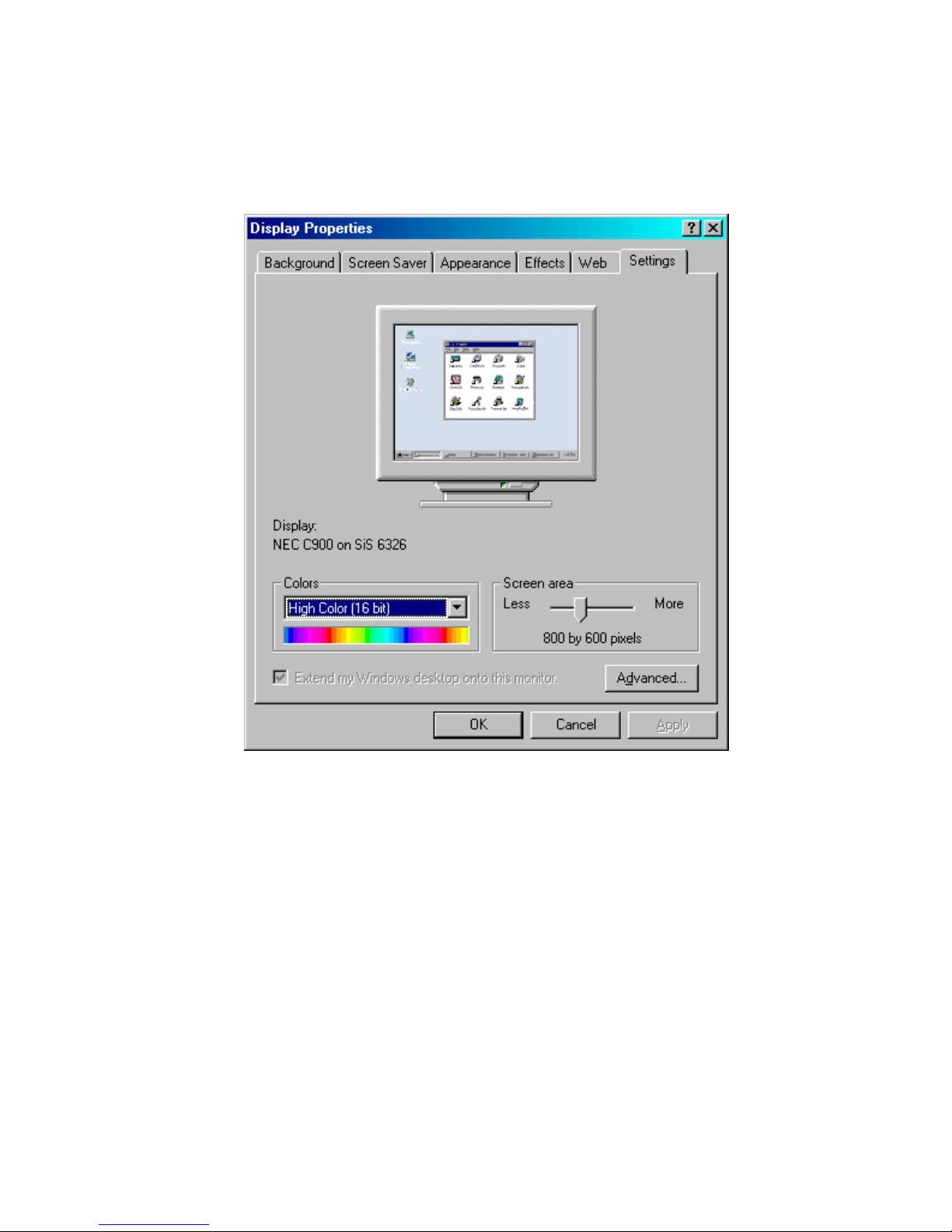
4.2.2 Installation for Windows 98
1. Select "Start", "Settings", "Control Panel", double click "Display",
press "Settings," then press the "Advanced..." button.
PCM-9340 User’s Manual 44
Page 53
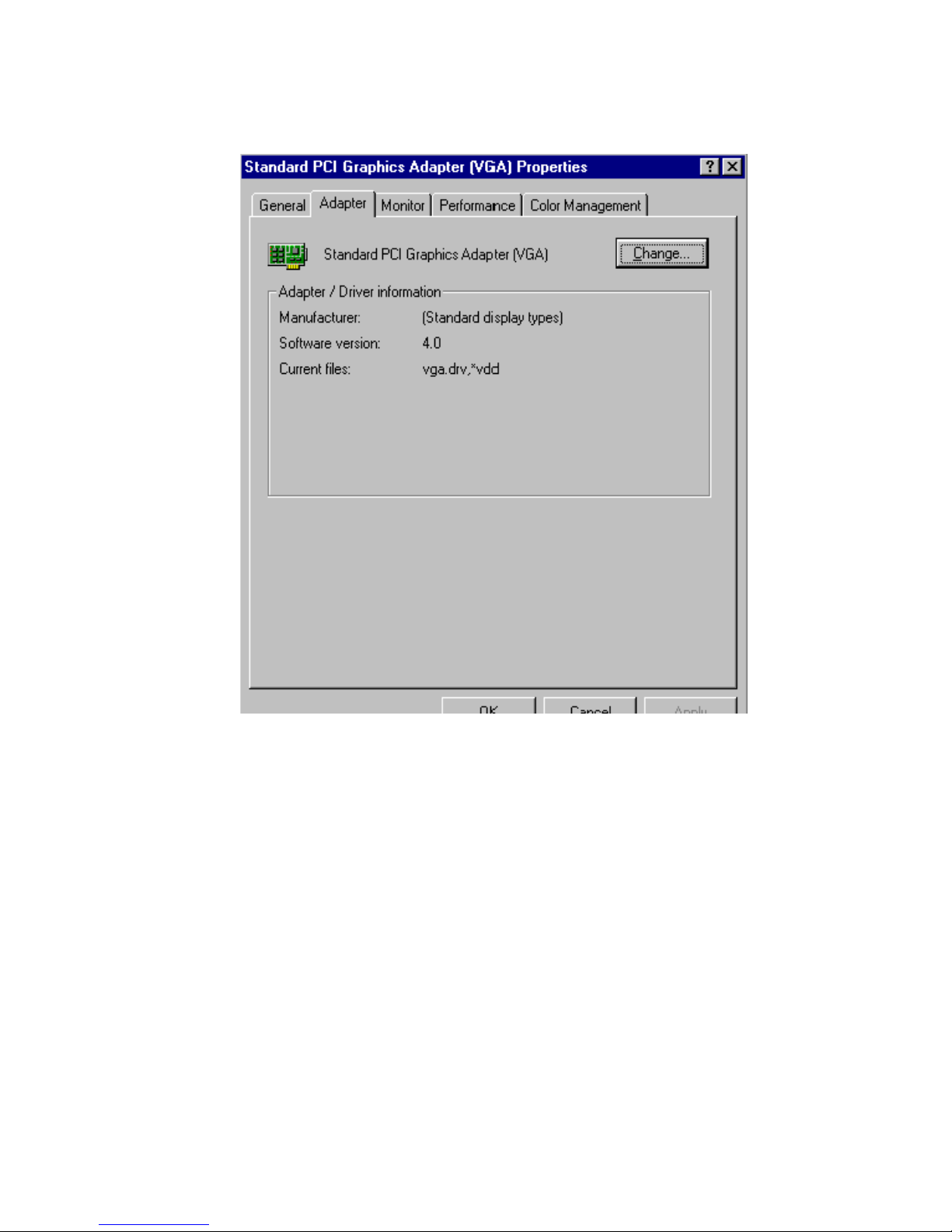
2. Select “Adapter,” then “Change.”
45 Chapter 4 SVGA Setup
Page 54
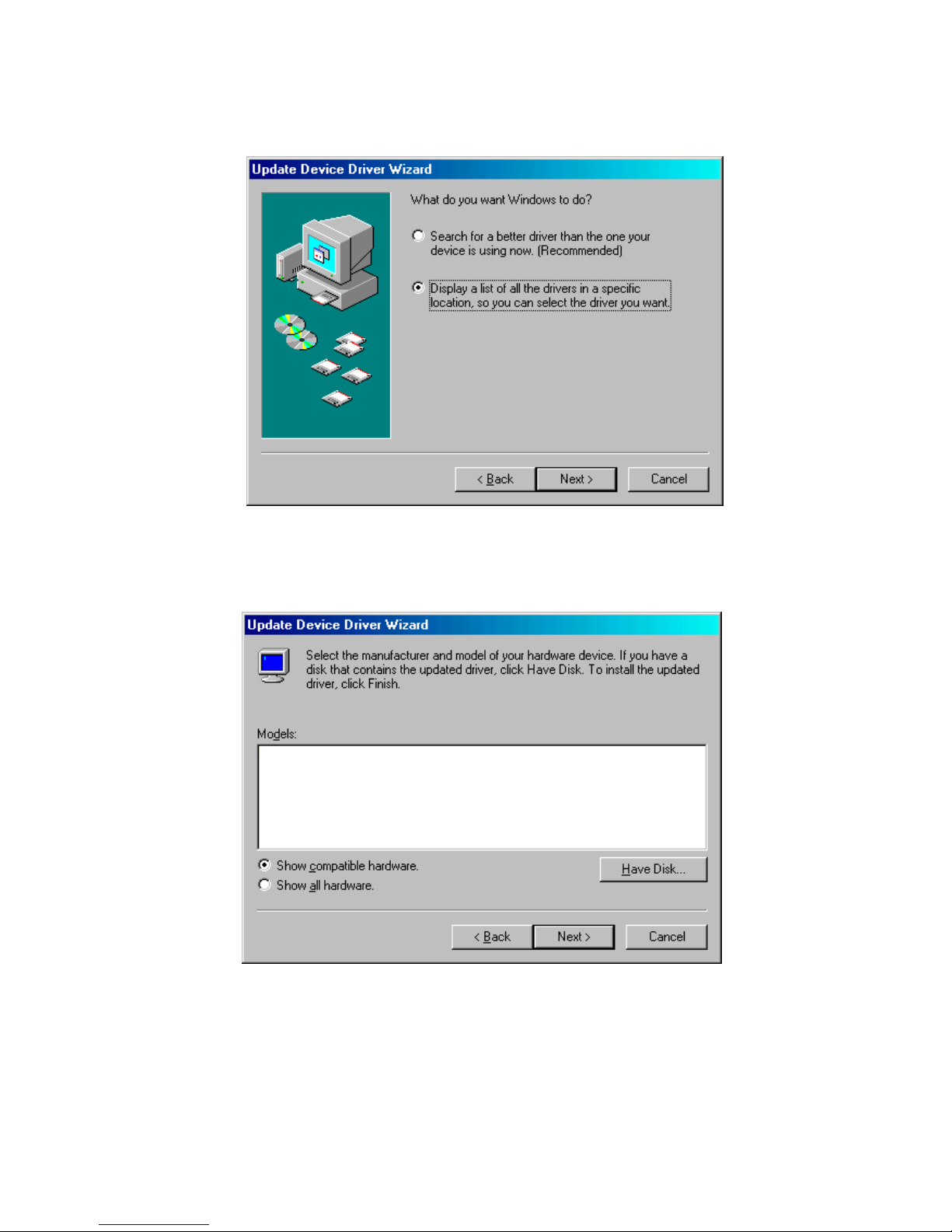
3. Select “Display a list of all....” and press “Next.”
4. Press the “Have disk...” button.
PCM-9340 User’s Manual 46
Page 55
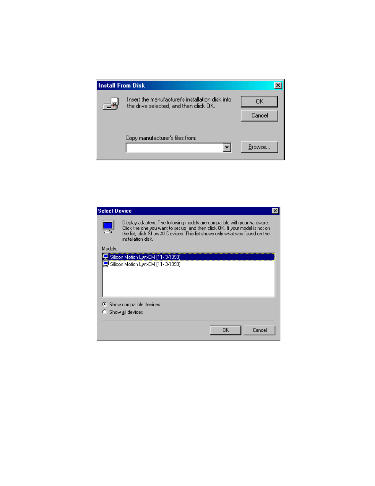
5. Insert the CD into the CD-ROM drive. Type in the path to the CD-
ROM, then press “OK”
D:\VGA\WIN98
6. Select the highlighted item, then click “OK.”
47 Chapter 4 SVGA Setup
Page 56
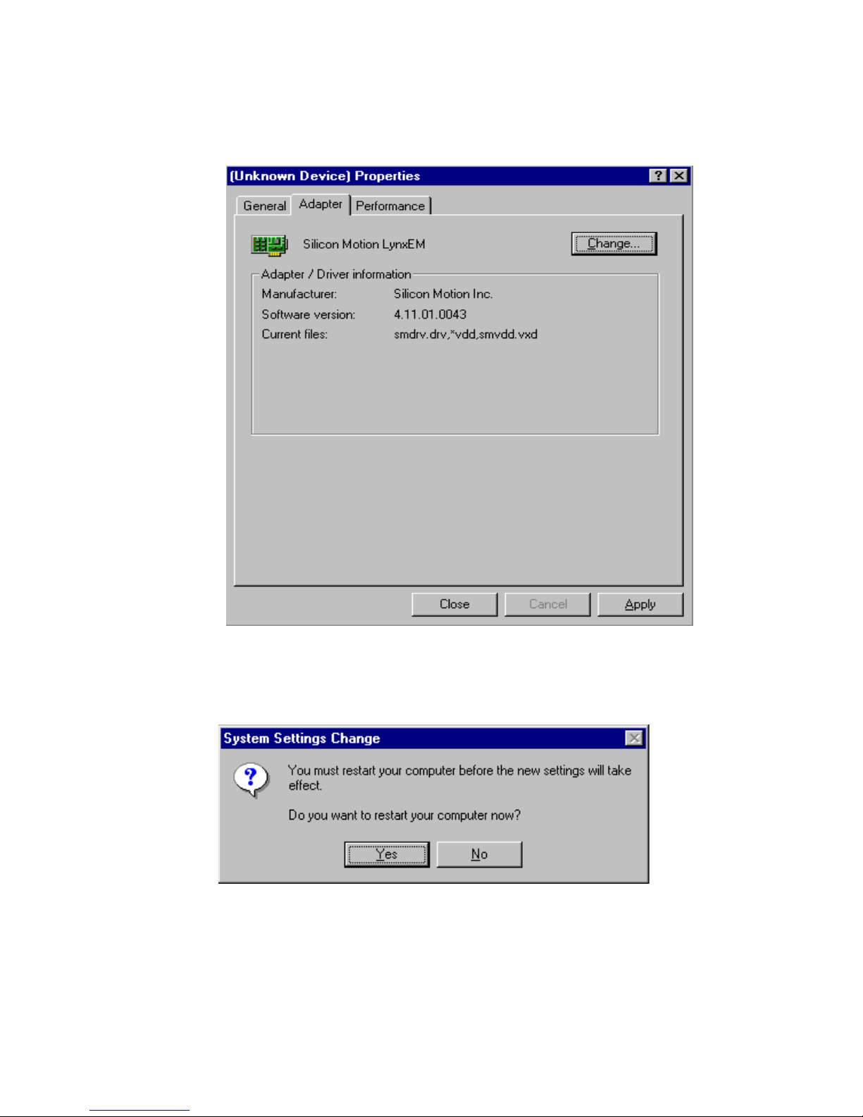
7. "Silicon Motion LynxEM" appears under the adapter tab. Click the
"Apply" button.
8. Press “Yes” to reboot.
PCM-9340 User’s Manual 48
Page 57
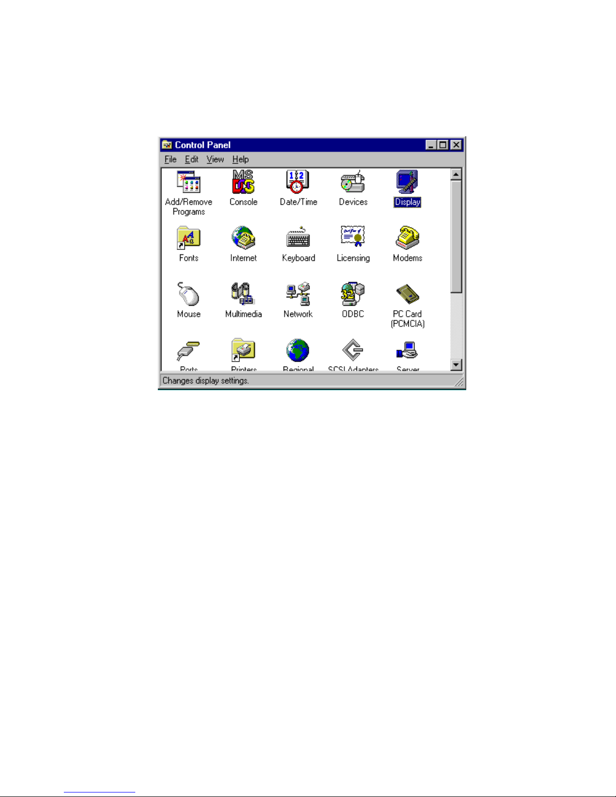
4.2.3 Installation for Windows NT
1. Select "Start", "Settings", "Control Panel" and double click the
"Display" icon.
49 Chapter 4 SVGA Setup
Page 58

2. Choose the "Settings" tab, and press the "Display Type" button.
PCM-9340 User’s Manual 50
Page 59
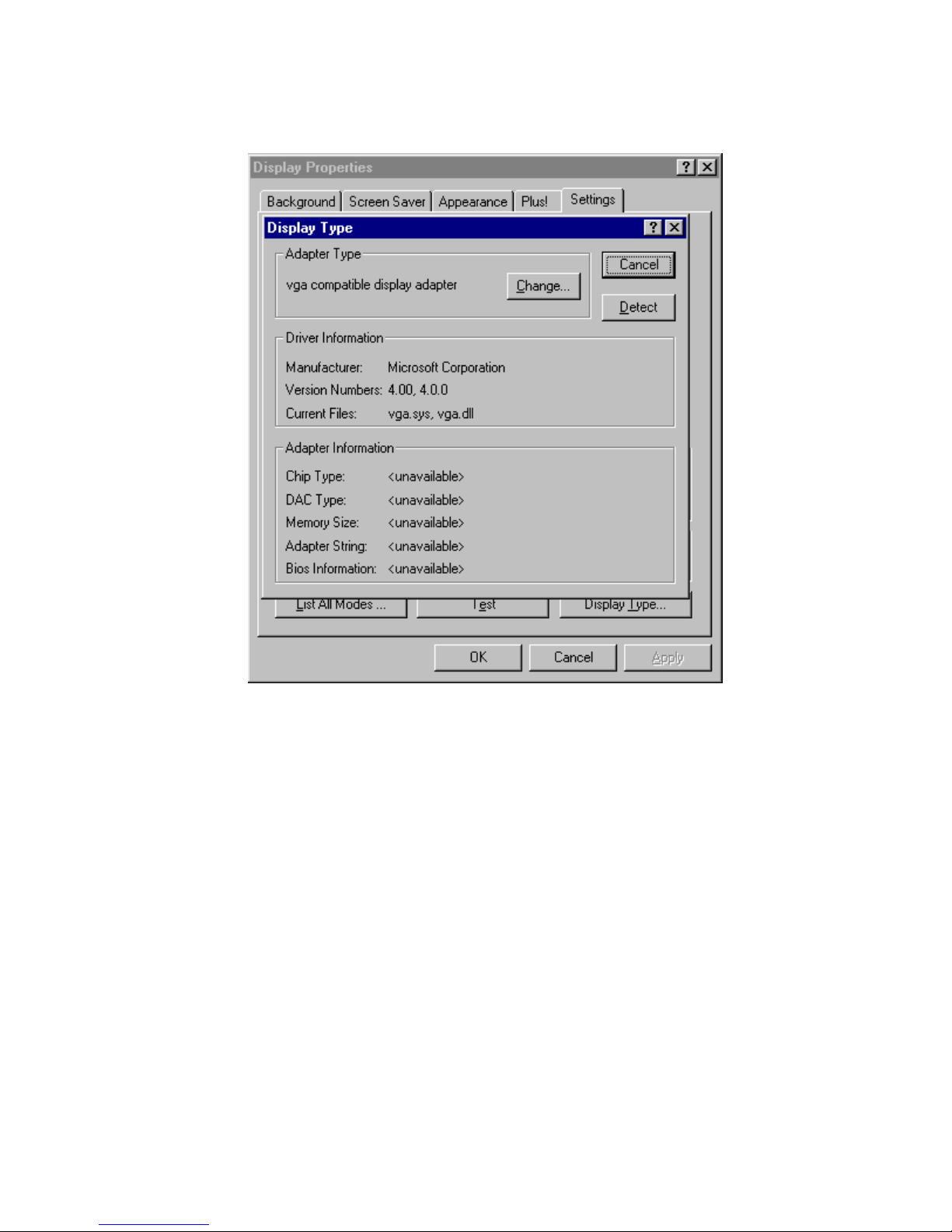
3. Press the "Change..." button.
51 Chapter 4 SVGA Setup
Page 60
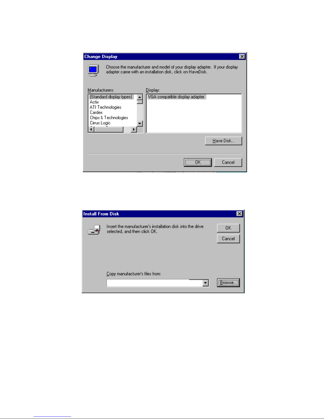
4. Click the "Have Disk..." button.
5. Type the path to the CD-ROM, and press the “OK” button.
D:\VGA\WIN_NT
PCM-9340 User’s Manual 52
Page 61
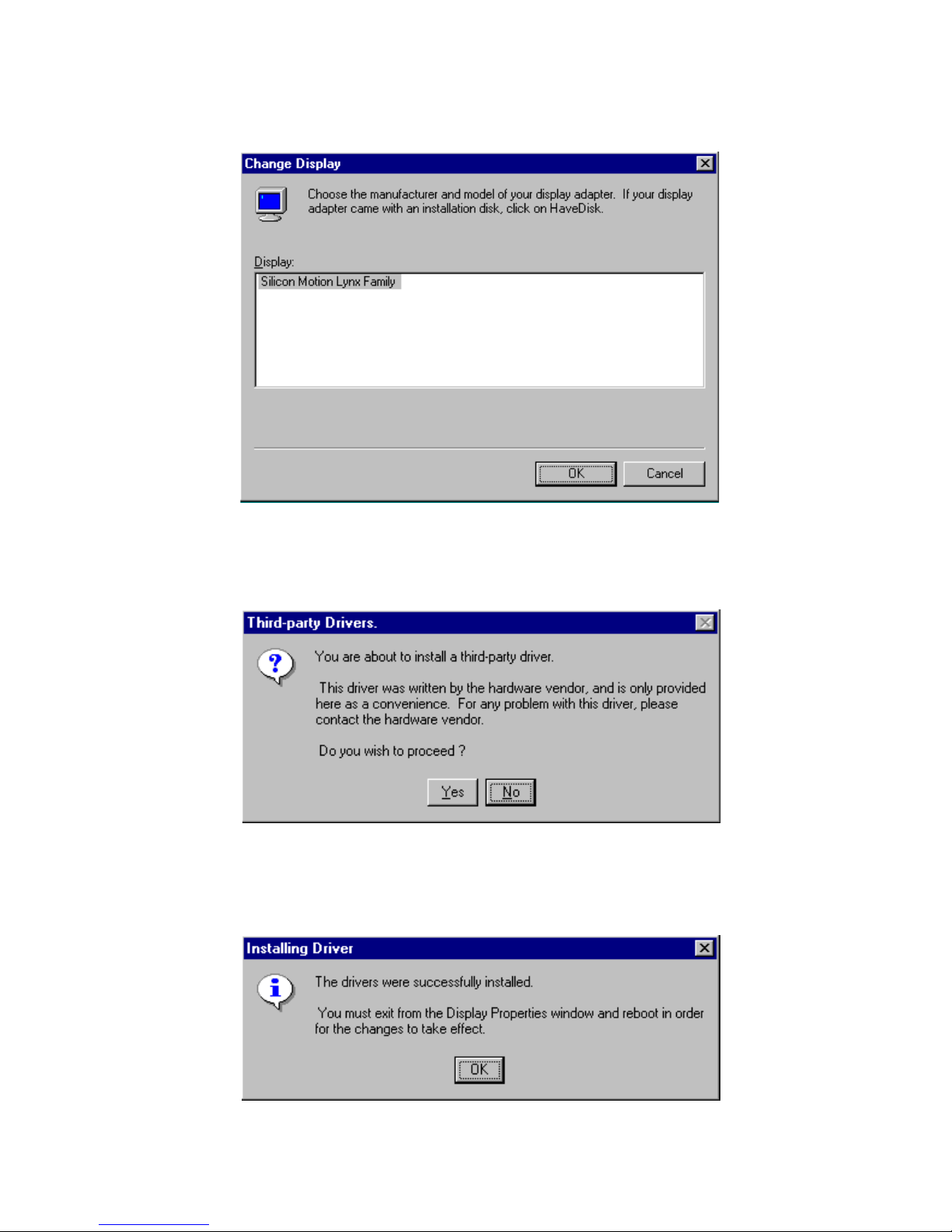
6. Select the highlighted item, and click the "OK" button.
7. Press "Yes" to proceed.
8. Press "OK" to reboot.
53 Chapter 4 SVGA Setup
Page 62

4.3 Further Information
For further information about the AGP/SVGA installation in your PCM9340, including driver updates, troubleshooting guides and FAQ lists,
visit the following web resources:
VIA website: www.via.com.tw
EMAC website: www.emacinc.com
PCM-9340 User’s Manual 54
Page 63

Chapter 7 PCI Bus Etherne t Interface
PCI Bus Ethernet
Interface
This chapter provides information on
Ethernet configuration.
Introduction
Installation of Ethernet drivers for
Windows 95/98/NT
Further information
5
CHAPTER
55 Chapter 5 PCI Bus Ethernet Interface
Page 64

Chapter 5 PCI Bus Ethernet Interface
5.1 Introduction
The PCM-9340 is equipped with a high performance 32-bit Ethernet
chipset which is fully compliant with IEEE 802.3 100 Mbps CSMA/CD
standards. It is supported by major network operating systems. It is also
both 100Base-T and 10Base-T compatible. The medium type can be configured via the RSET8139.exe program included on the utility disk.
The Ethernet port provides a standard RJ-45 jack onboard (CN6). The
network boot feature can be utilized by incorporating the boot ROM
image files for the appropriate network operating system. The boot ROM
BIOS files are combined with system BIOS, which can be enabled/disabled in the BIOS setup.
5.2 Ethernet Driver Installation
Before installing the Ethernet driver, note the procedures below. You
must know which operating system you are using in your PCM-9340
Series, and then refer to the corresponding installation steps. You will
quickly and successfully complete the installation, even if you are not
familiar with instructions for MS-DOS or Windows.
Note:
PCM-9340 User’s Manual 56
The windows illustrations in this chapter are
examples only. Follow the steps and pay attention to the instructions which appear on your
screen.
Page 65
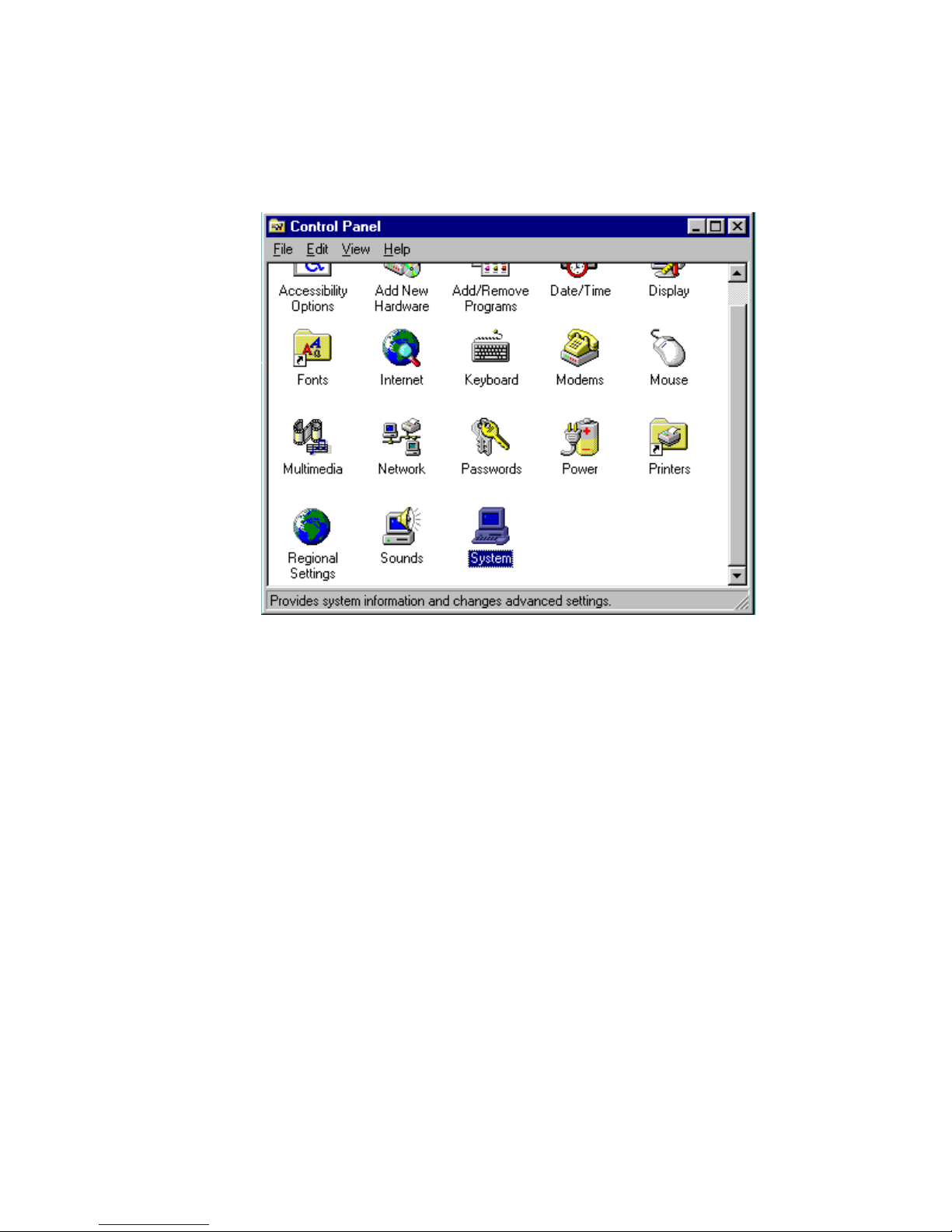
5.2.1 Installation for Windows 95
1. a. Select "Start", "Settings". "Control Panel"
b. Double click "System".
57 Chapter 5 PCI Bus Ethernet Interface
Page 66
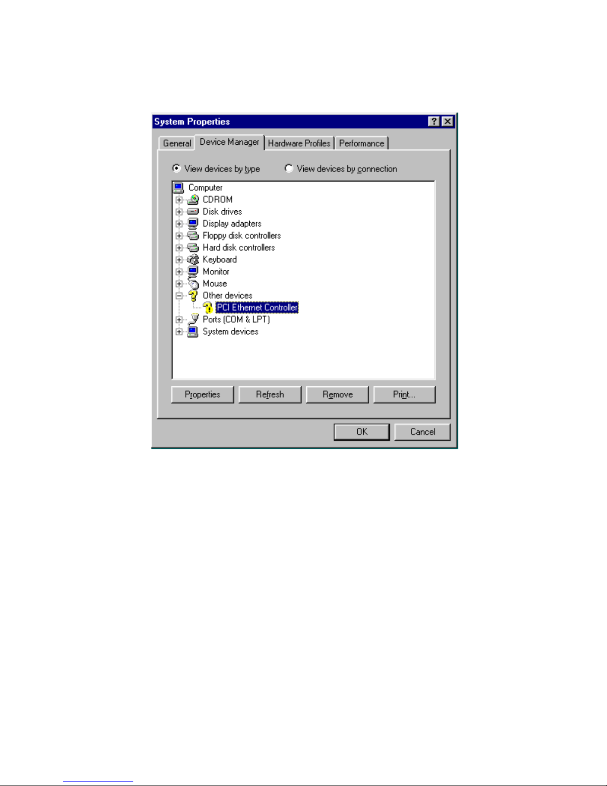
2. Click "Device Manager" folder, then double click "PCI Ethernet
Controller."
PCM-9340 User’s Manual 58
Page 67
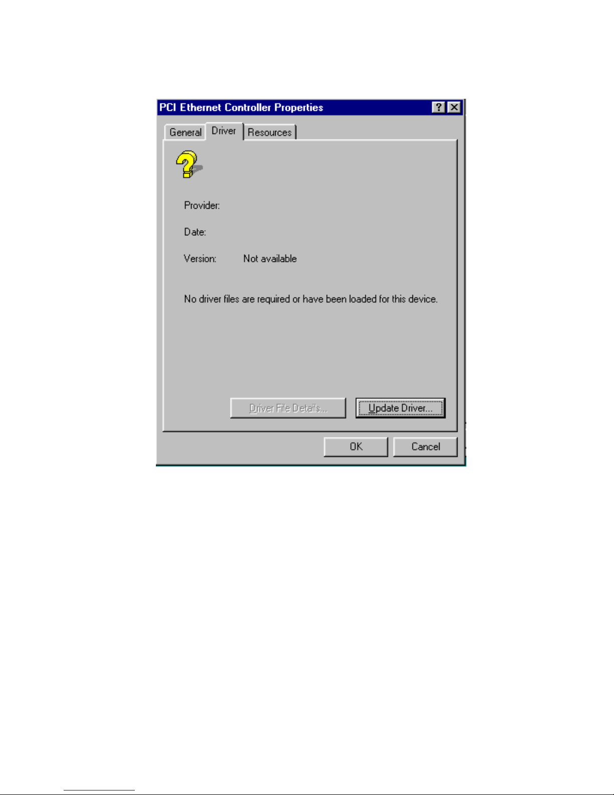
3. Select the "Driver" tab, then click "Update Driver ..."
59 Chapter 5 PCI Bus Ethernet Interface
Page 68
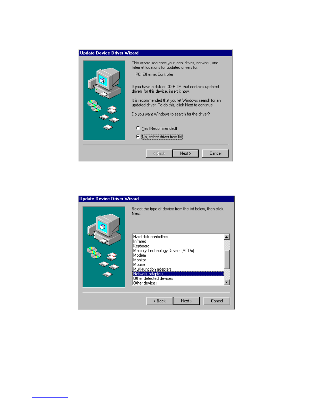
4. Select "No, select driver from list," and click the "NEXT" button.
5. Highlight "Network Adapters" then click the "NEXT" button.
PCM-9340 User’s Manual 60
Page 69
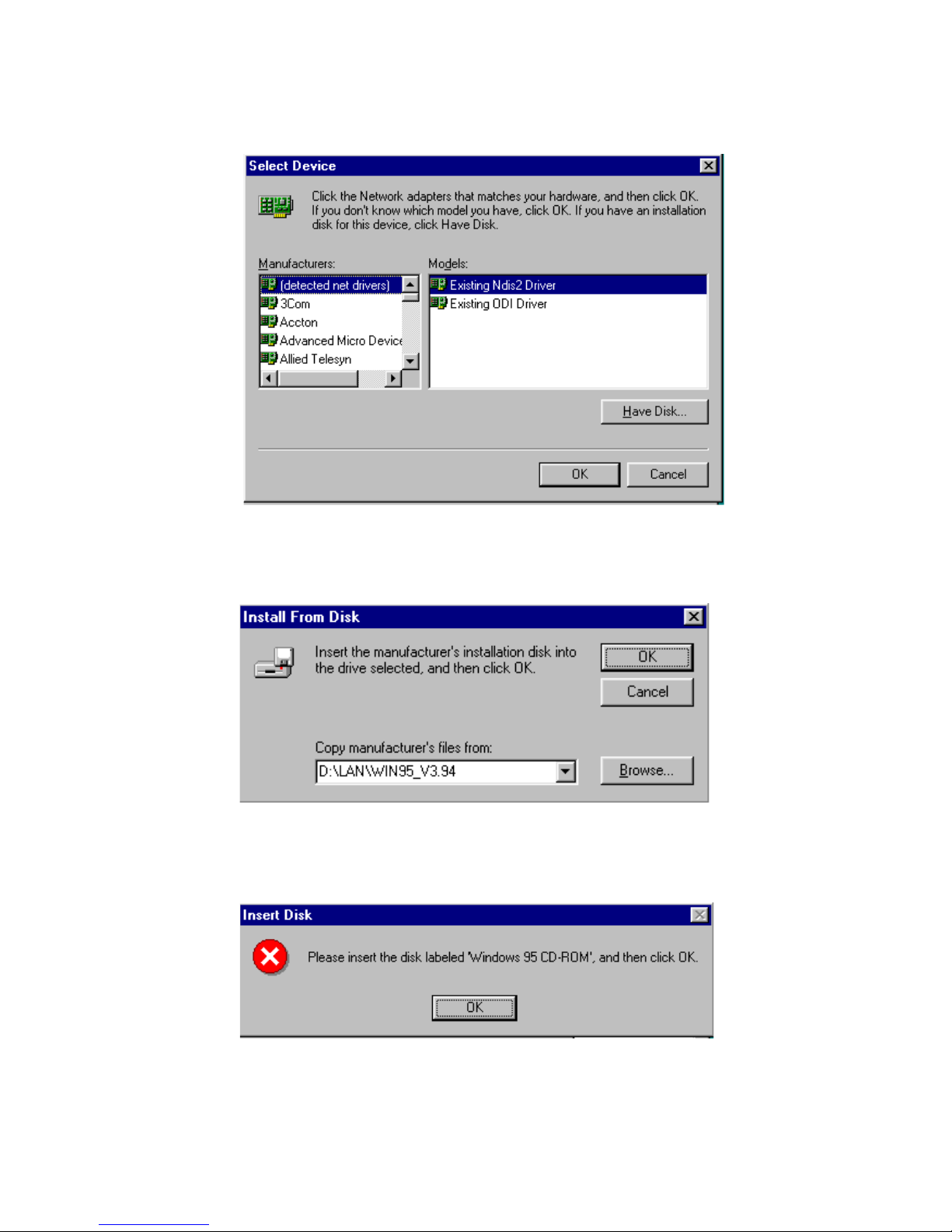
6. Click "Have Disk..." to update the LAN driver.
7. Direct the path to the LAN driver to install it.
8. Insert the Windows 95 CD and click "OK."
61 Chapter 5 PCI Bus Ethernet Interface
Page 70
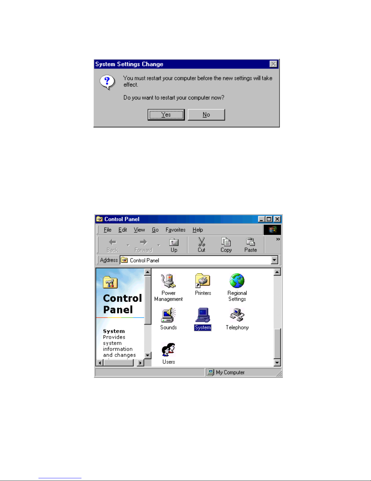
9. Reboot the system.
5.2.2 Installation for Windows 98
1. a. Select "Start", "Settings". "Control Panel".
b. Double click on the "System" icon.
PCM-9340 User’s Manual 62
Page 71
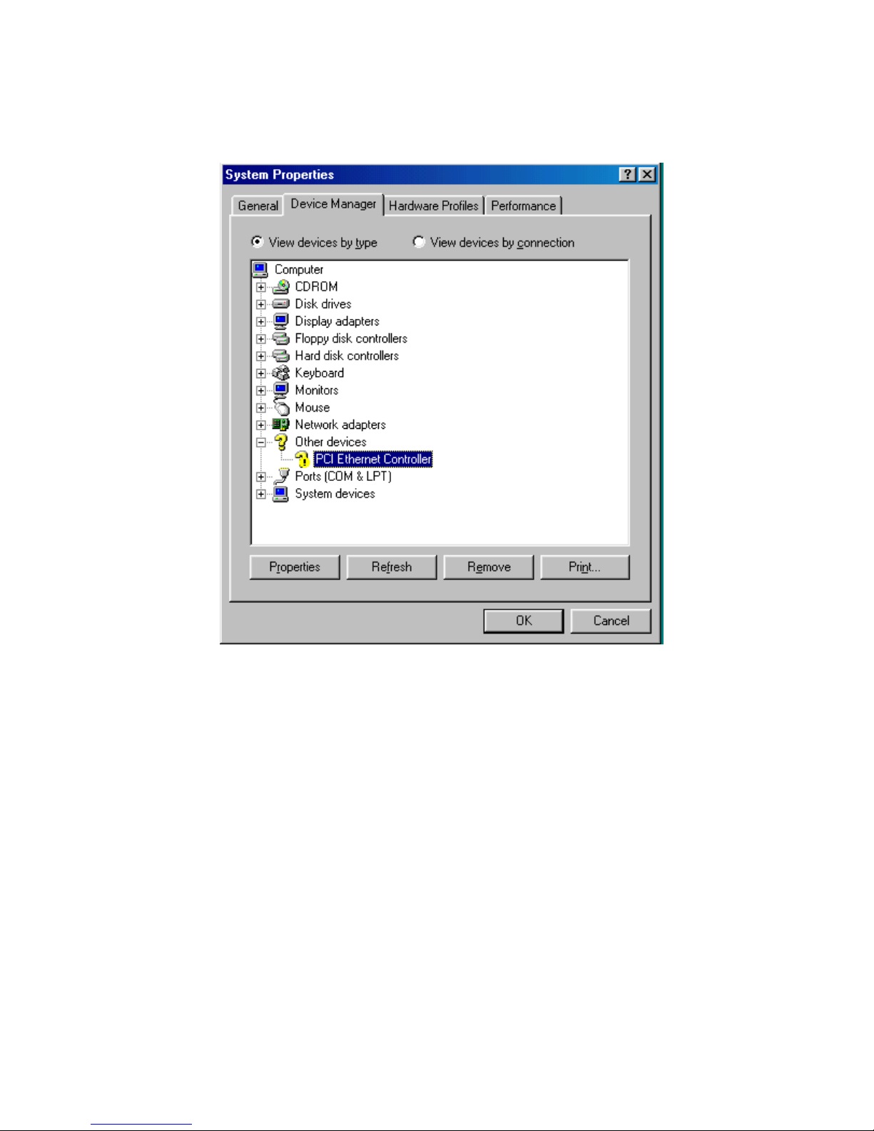
2. Click the "Device Manager" tab, then highlight "PCI Ethernet Con-
troller"
63 Chapter 5 PCI Bus Ethernet Interface
Page 72
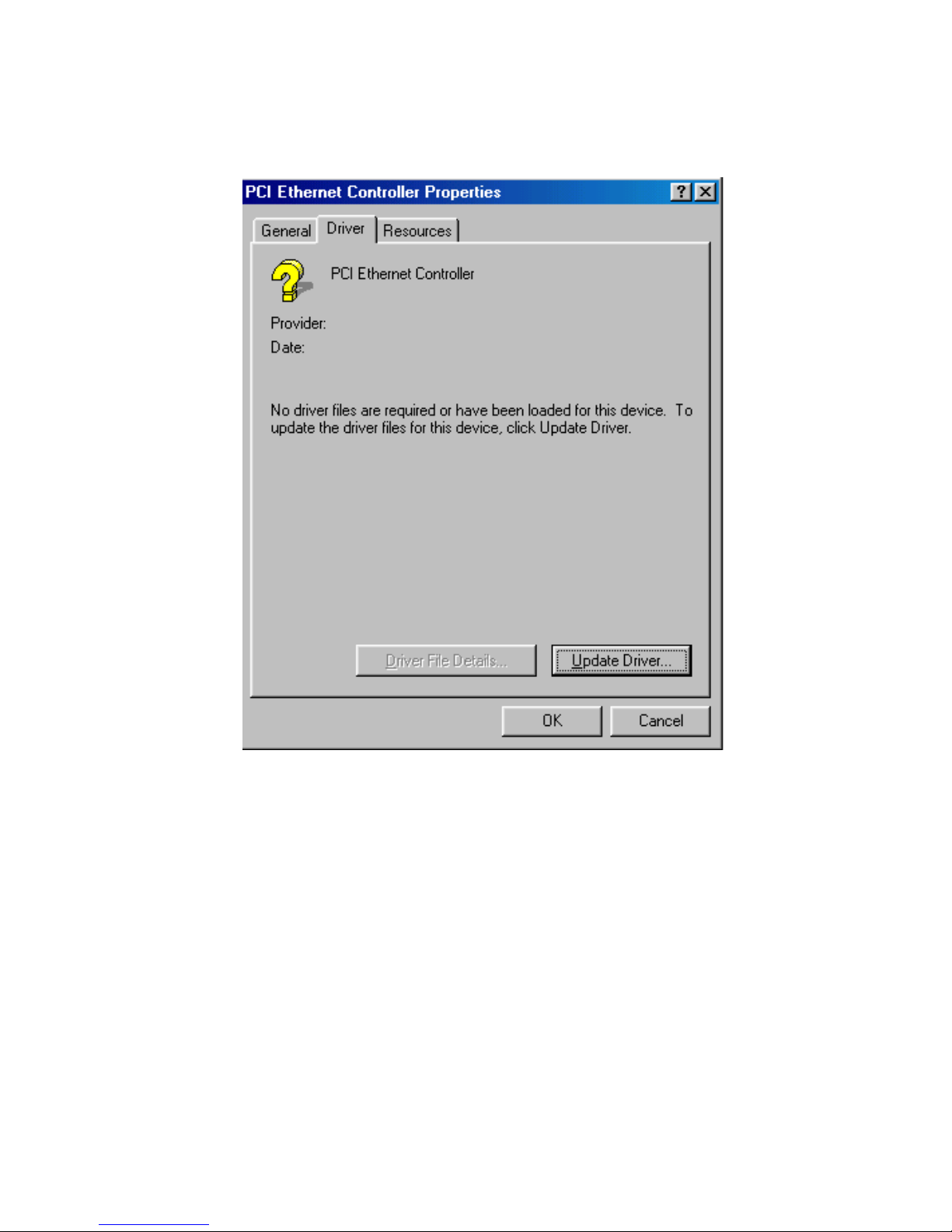
3. Click on "Properties," select the "Driver" tab, then "Update
Driver..."
PCM-9340 User’s Manual 64
Page 73
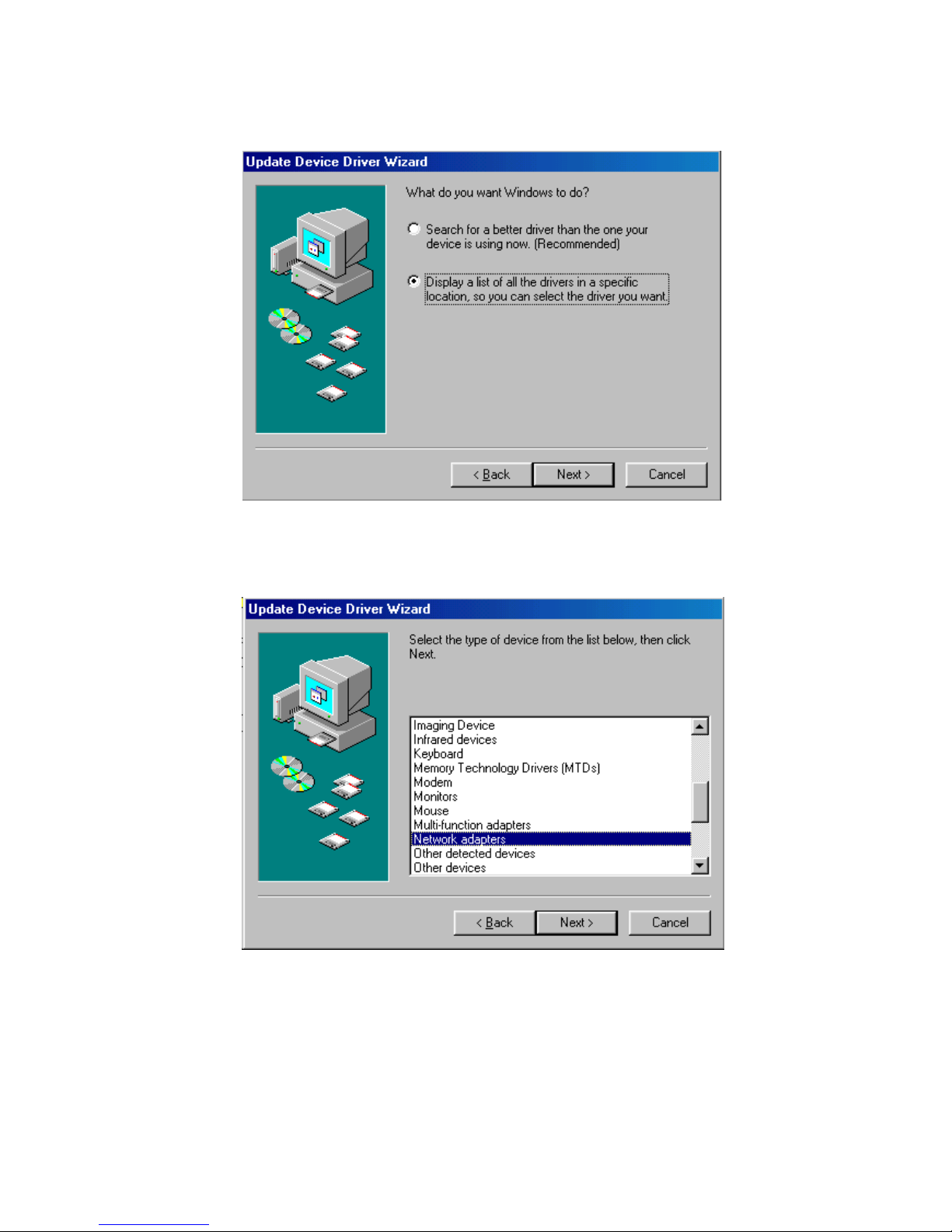
4. Select "Display a list of all the...." then hit "NEXT."
5. Select "Network adapters," and click the "NEXT" button.
65 Chapter 5 PCI Bus Ethernet Interface
Page 74
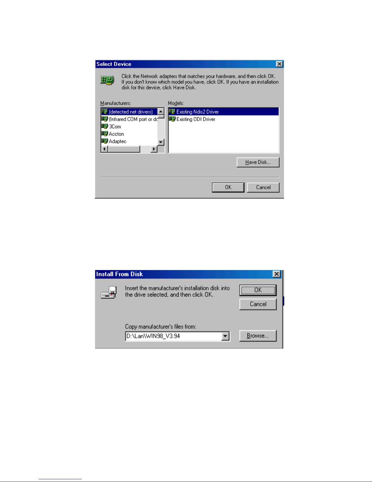
6. Click the "Have Disk..." button.
7. a. Insert the CD ROM.
b. Type “D:\LAN\WIN98_V3.94” (where D: represents your
CDROM drive).
c. Click “OK”.
PCM-9340 User’s Manual 66
Page 75
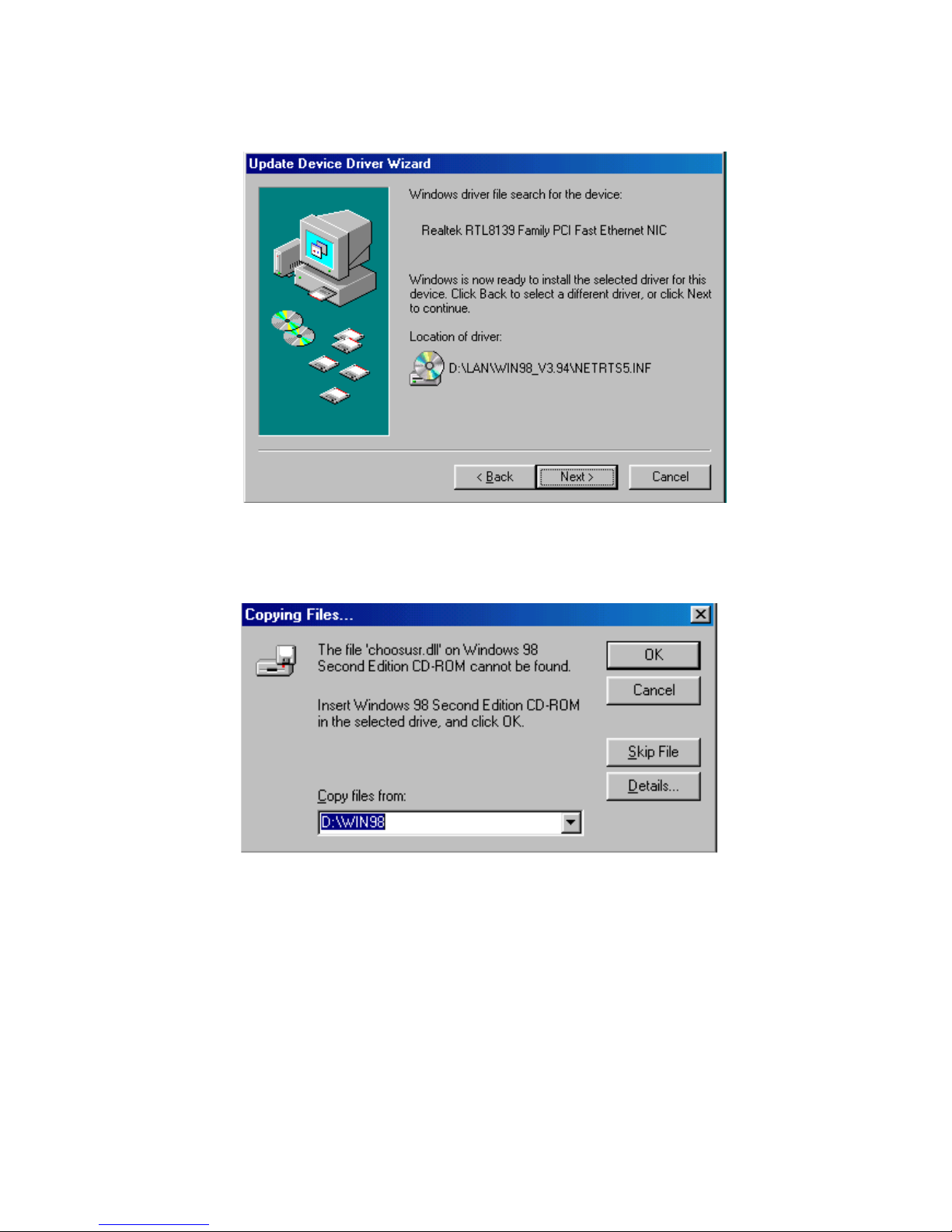
8. The system will now install the driver.
9. Insert the Windows 98 CD in the CDROM drive.
67 Chapter 5 PCI Bus Ethernet Interface
Page 76
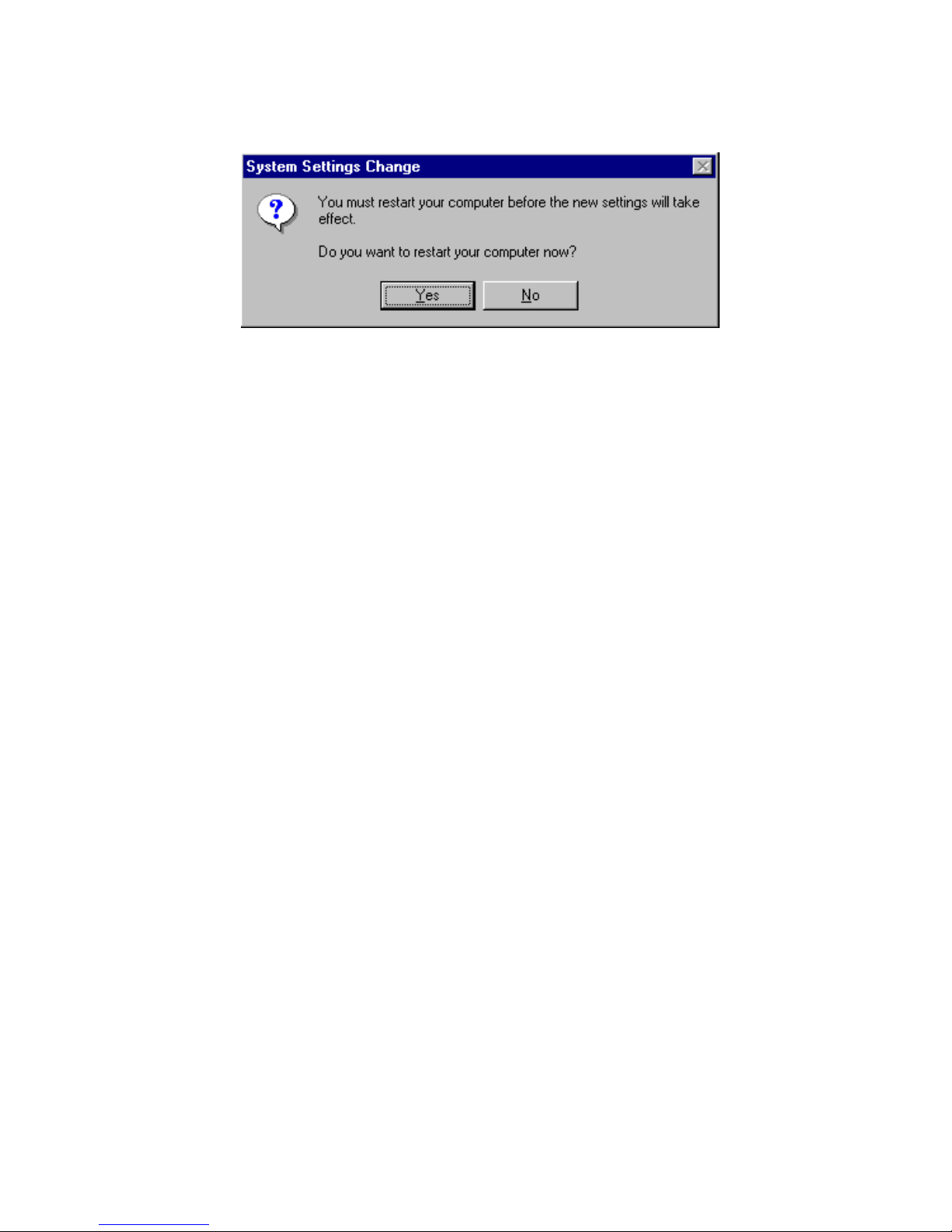
10. Reboot the system.
PCM-9340 User’s Manual 68
Page 77
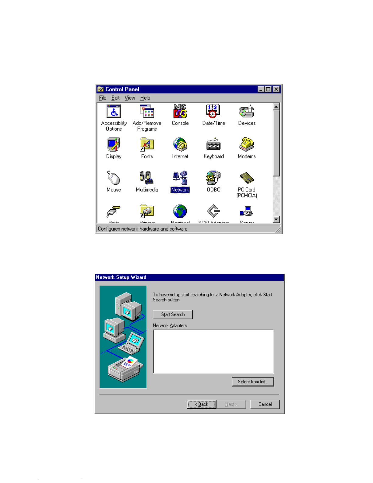
5.2.3 Installation for Windows NT
1. a. Select “Start,” “Settings,” and “Control Panel.”
b. Double click “Network”.
2. Click on "Select from list."
69 Chapter 5 PCI Bus Ethernet Interface
Page 78
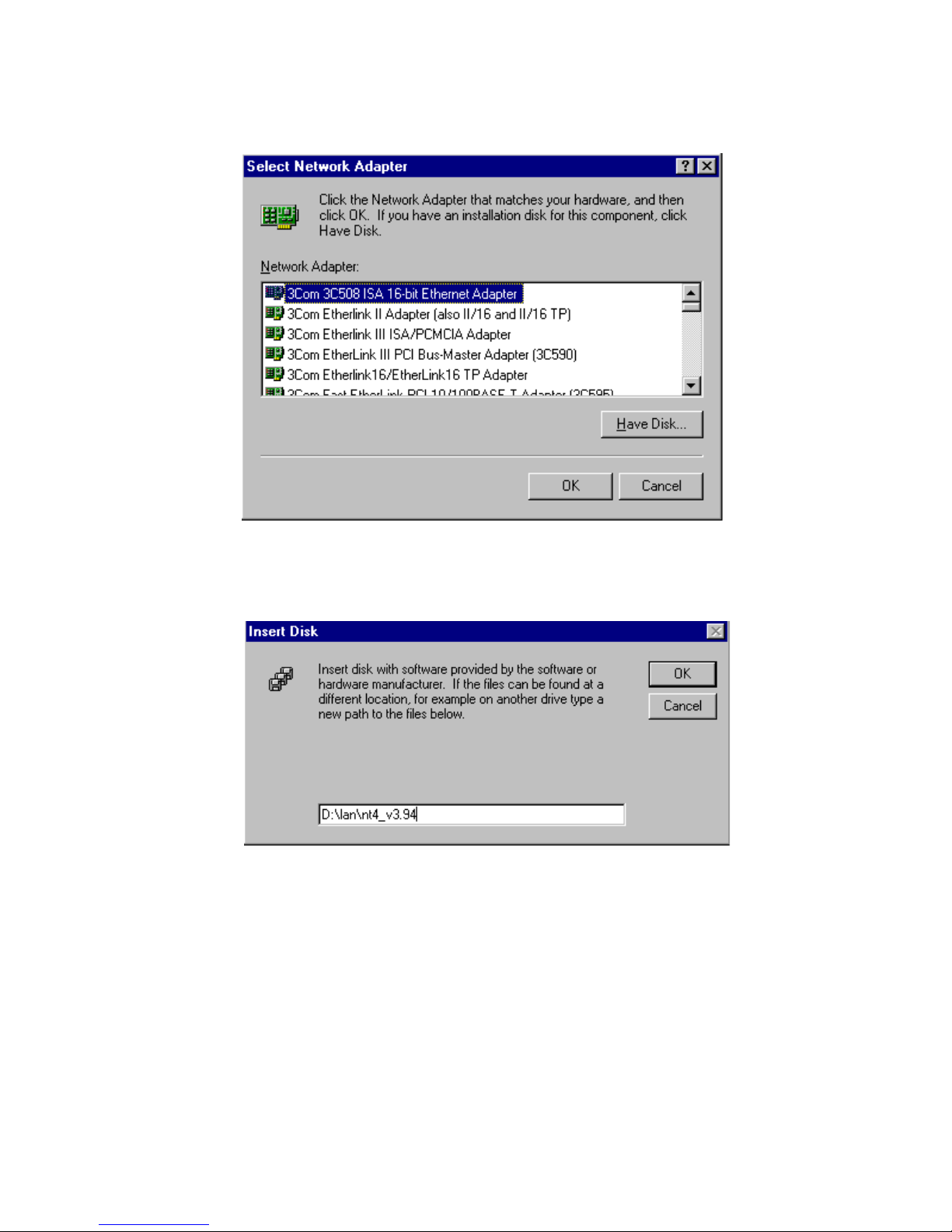
3. Click "Have Disk..."
4. Type in the path, then click "OK."
PCM-9340 User’s Manual 70
Page 79
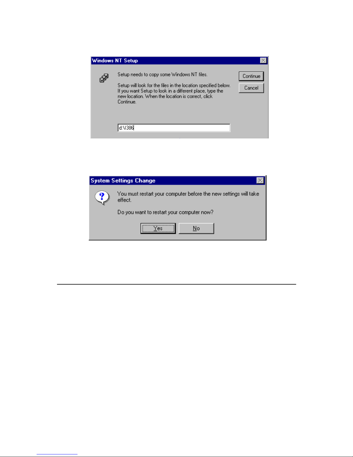
5. Insert the Windows NT CD.
6. Reboot.
5.3 Further information
Realtek website: www.realtek.com.tw
EMAC website: www.emacinc.com
71 Chapter 5 PCI Bus Ethernet Interface
Page 80

PCM-9340 User’s Manual 72
Page 81

Chapter 6 Audio Setup
6
CHAPTER
Audio Setup
The PCM-9340 is equipped with an audio
interface that records and plays back
CD-quality audio. This chapter provides
instructions for installing the software drivers
for Windows 95/98/NT
73 Chapter 6 Audio Setup
Page 82

Chapter 6 Audio Setup
6.1 Introduction
The PCM-9340 on-board audio interface provides high-quality stereo
sound and FM music synthesis (ESFM) by using the ES1373 audio controller from Creative Technology Ltd. The audio interface can record,
compress, and play back voice, sound, and music with a built-in mixer
control. The PCM-9340's on-board audio interface also supports the Plug
and Play (PnP) standard and provides PnP configuration for audio, FM,
and MPU-104 logical devices. It is compatible with AC97 version 2.0,
voice, and music functions. The ESFM synthesizer is register compatible
with the OPL3 and has extended capabilities.
6.2 Audio Driver Installation
Before installing the audio driver, please take note of the procedures
detailed below. You must know which operating system you are using in
your PCM-9340, and then refer to the corresponding installation flow
chart. Just follow the steps in the flow chart. You can quickly and successfully complete the installation, even though you are not familiar with
instructions for Windows.
Notes:
PCM-9340 User’s Manual 74
1. The CD-ROM drive is designated as "D"
throughout this chapter.
2. For Windows 98, in step 1 the path is:
D:/Biscuit/9340/audio/Win98/setup.exe.
For Windows 2000, in step 1 the path is:
D:/Biscuit/9340/audio/win2k/setup.exe.
For Windows NT, in step 1 the path is:
D:/Biscuit/9340/audio/winnt/setup.exe.
Page 83
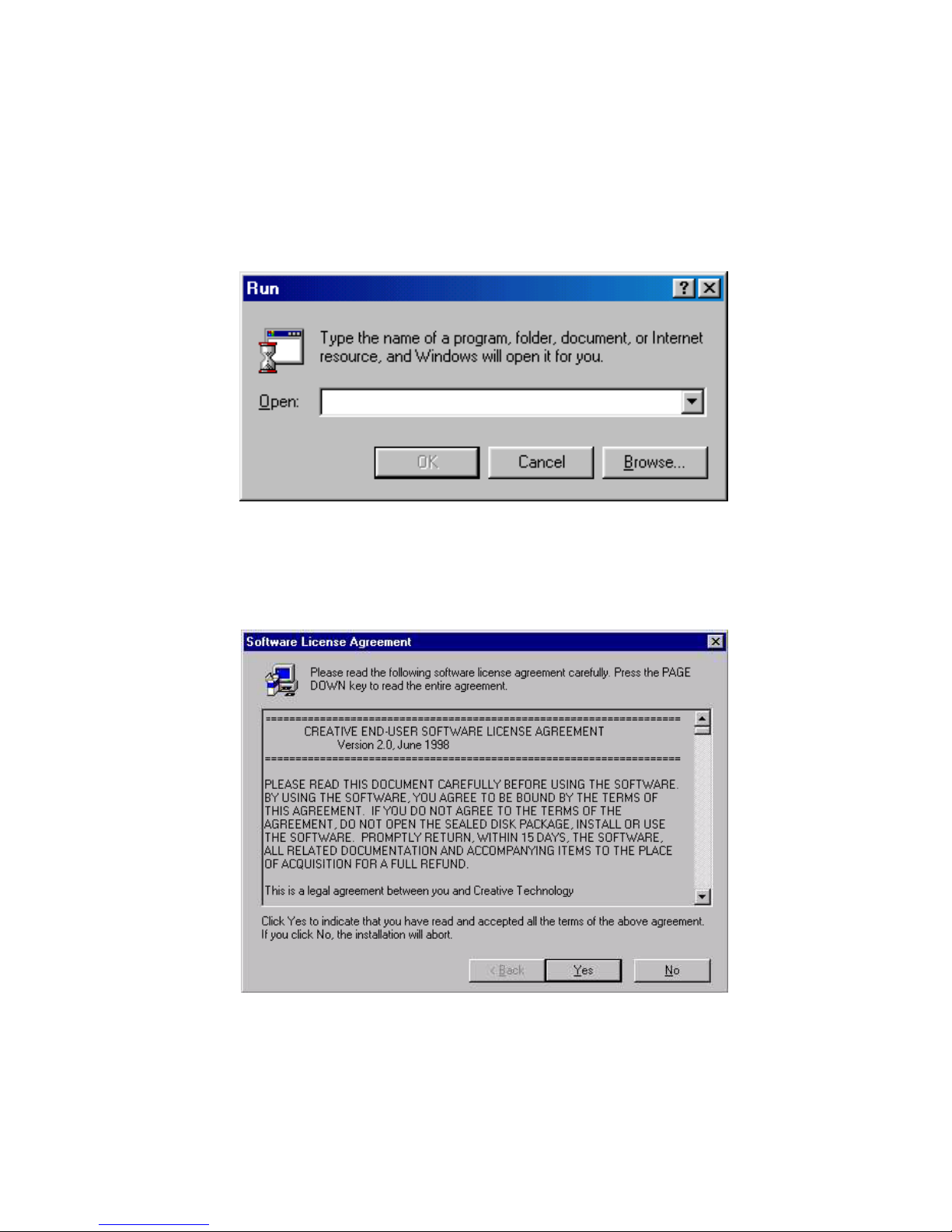
6.2.1 Installation for Windows 95/98/NT
1. a. Select "Start", "Run"
b. Type in the correct path
D:\Biscuit\9340\Audio\Winxx\
c. Click the "OK" button.
D:\biscuit\9340\audio\Win95
2. a. Click "Yes" to accept the agreement.
b. On the next page, read the Readme file, then click "Next.".
75 Chapter 6 Audio Setup
Page 84
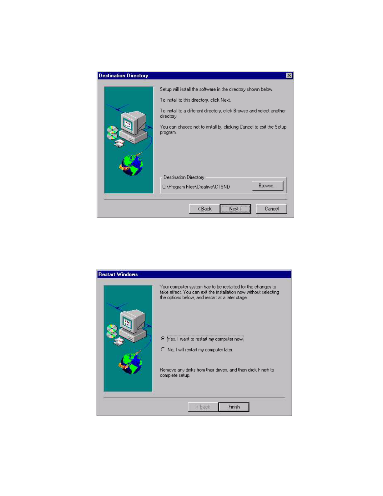
3. a. Click "Next" to continue
b. Follow the procedure which appears on your screen.
4. After installation, select "Yes" and click "Finish" to restart the com-
puter.
PCM-9340 User’s Manual 76
Page 85

Appendix A Programming the Watchdog Timer
A
Appendix
Programming the
Watchdog Timer
The PCM-9340 is equipped with
a watchdog timer that resets the CPU or
generates an interrupt if processing comes
to a standstill for any reason. This
feature ensures system reliability in
industrial standalone or unmanned environments.
77 Appx. A
Page 86

Appendix A Programming the Watchdog
Timer
A.1 Supported Input Timing Modes
In order to program the watchdog timer, you must write a program which
writes I/O port address 443 (hex). The output data is a value of time interval. The value range is from 01 (hex) to 3E (hex), and the related time
interval is 1 sec. to 62 sec.
Data Time Interval
01 1 sec.
02 2 sec.
03 3 sec.
04 4 sec.
.
.
.
3E 62 sec.
After data entry, your program must refresh the watchdog timer by
rewriting the I/O port 443 (hex) while simultaneously setting it.
When you want to disable the watchdog timer, your program
should read I/O port 443 (hex).
TPC-642 User’s Manual 78
Page 87

The following example shows how you might program the watchdog
timer in BASIC:
10 REM Watchdog timer example program
20 OUT &H443, data REM Start and restart the
watchdog
30 GOSUB 1000 REM Your application task #1
40 OUT &H443, data REM Reset the timer
50 GOSUB 2000 REM Your application task #2
60 OUT &H443, data REM Reset the timer
70 X=INP (&H443) REM Disable the watchdog timer
80 END
1000 REM Subroutine #1, your application task
.
.
.
1070 RETURN
2000 REM Subroutine #2, your application task
.
.
.
2090 RETURN
79 Appx. A
Page 88

TPC-642 User’s Manual 80
Page 89

Appendix B Installing PC/104- plus Modules
Installing
PC/104 Modules
This appendix gives instructions for
installing PC/104 modules.
B
Appendix
81 Appx. B
Page 90

Appendix B Installing PC/104 Modules
B.1 Installing PC/104 Modules
The PCM-9340's PC/104 connectors give you the flexibility to attach PC/
104 modules.
Installing these modules on the PCM-9340 is quick and simple. The following steps show to mount the PC/104 modules:
1. Remove the PCM-9340 from your system, paying particular atten-
tion to the safety instructions mentioned previously.
2. Make any jumper or link changes required to the biscuit SBC now.
Once the PC/104 module is mounted, you may have difficulty in
accessing these.
3. Normal PC/104 modules have male connectors and mount directly
onto the main card. (Refer to the diagram on the following page.)
4. Mount the PC/104 module onto the biscuit SBC by pressing the
module firmly but carefully onto the mounting connectors.
5. Secure the PC/104 module onto the biscuit SBC using the four
mounting spacers and screws.
PCM-9340 User’s Manual 82
Page 91
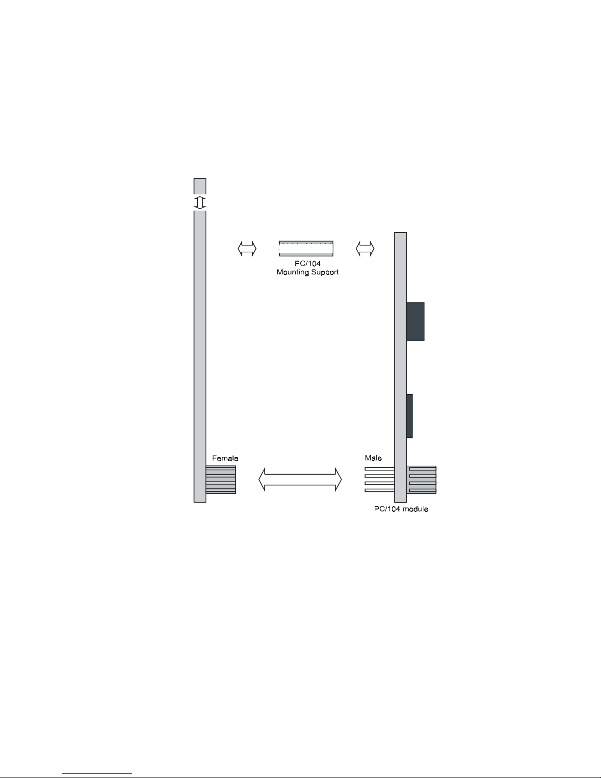
PCM-9340
Figure B.1: PC/104 module mounting diagram
83 Appx. B
Page 92
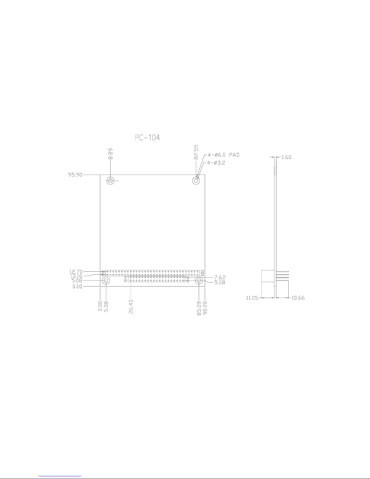
Figure B.2: PC/104 module dimensions (mm) (±0.1)
PCM-9340 User’s Manual 84
Page 93

Appendix C Pin Assignments
C
Appendix
Pin Assignments
This appendix contains information of a
detailed or specialized nature. It includes:
• CPU Fan connector
• COM3/COM4 connector
• COM2 connector
• COM1 connector
• Ethernet connector
• PS/2 Keyboard PS/2 Mouse connector
• IR connector
• IDE hard drive connector
• CRT display connector
• Audio connector (optional)
• Backlight connector
• ATX feature connector
• Floppy disk connector
• Ext. flat panel connector
• Main power connector (+5 V, +12 V)
• CD Audio in
• Parallel port connector
• Flat panel connector
• GPIO connector
• Auxiliary power connector (-5 V, -12 V)
• ATX power button
85 Appx. C
Page 94
Appendix C Pin Assignments
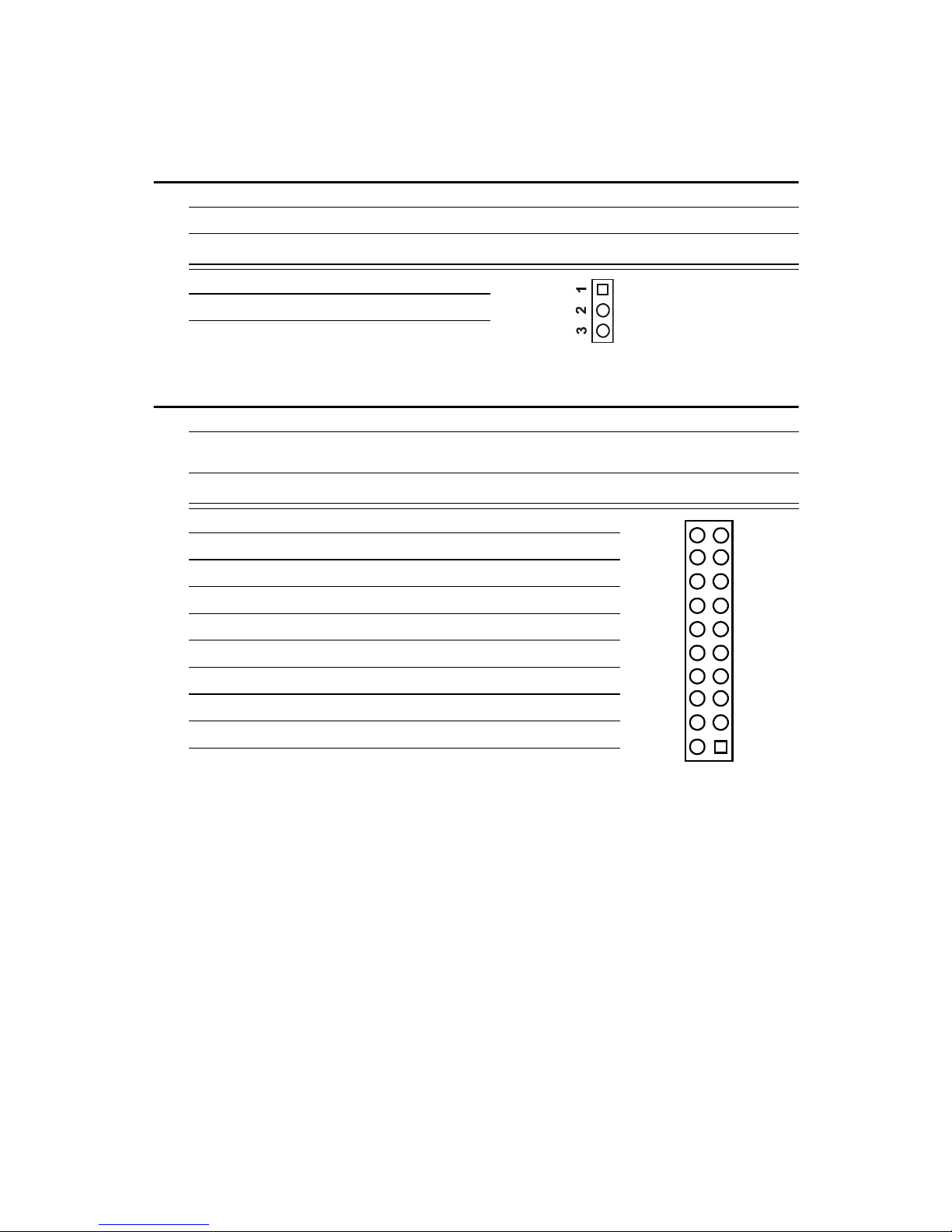
C.1 CPU fan power connector (CN1)
Table C.1: CPU fan power connector (CN1)
Pin Signal
1+5V
2GND
3 +12V
C.2 COM 3, COM 4 connector (CN2)
Table C.2: COM Port Connector (CN2)
Pin Signal Pin Signal
1 RLSD1 (DCD1) 2 DSR1
3RX1 4RTS1
5TX1 6CTS1
7DTR1 8RI1
20
18
19
17
9GND 10GND
11 RLSD2 (DCD2) 12 DSR2
13 RX2 14 RTS2
15 TX2 16 CTS2
17 DTR2 18 RI2
19 GND 20 GND
43
21
PCM-9340 User’s Manual 86
Page 95
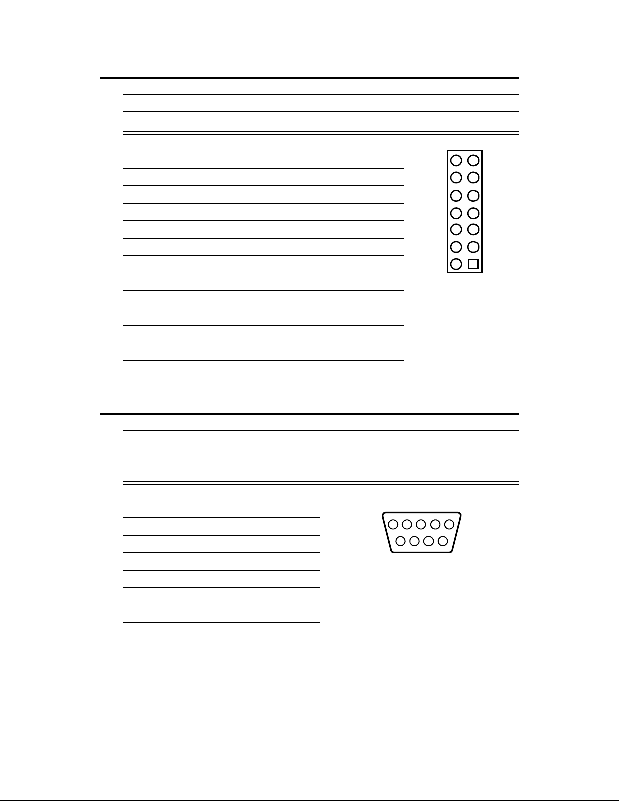
C.3 COM 2 connector (CN3)
Table C.3: COM2 RS-232/422/485 series port (CN3)
Pin RS-232 port RS-422 port RS-485 port
1DCD N/C N/C
2DSR N/C N/C
3RxD N/C N/C
4RTS N/C N/C
5TxD N/C N/C
6CTS N/C N/C
7DTR N/C N/C
8RI N/C N/C
9 GND N/C N/C
10 N/C N/C N/C
11 N/C TxD+ DATA +
12 N/C TxD- DATA13 N/C RxD+ N/C
14 N/C RxD- N/C
C.4 COM 1 RS-232 connector (CN4)
Table C.4: COM1 RS-232 connector
14
12
10
13
11
9
8
6
4
2
7
5
3
1
Pin Signal
1DCD
2RXD
3TXD
4DTR
5GND
6DSR
7RTS
8CTS
9RI
324
15
78
9
6
87 Appx. C
Page 96
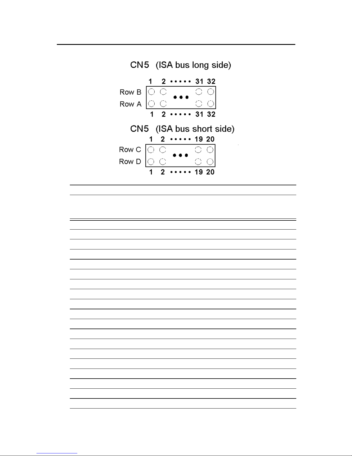
C.5 PC/104 Connector (CN5)
Table C.5: PC/104 connectors (CN5)
Pin Signal
Number Row A Row B Row C Row D
0— — 0V 0 V
1 IOCHCHK* 0 V SBHE* MEMCS16*
2 SD7 RESETDRV LA23 IOCS16*
3 SD6 +5 V LA22 IRQ10
4 SD5 IRQ9 LA21 IRQ11
5 SD4 -5 V LA20 IRQ12
6 SD3 DRQ2 LA19 IRQ15
7 SD2 -12 V LA18 IRQ14
8 SD1 ENDXFR* LA17 DACK0*
9 SD0 +12 V MEMR* DRQ0
10 IOCHRDY N/C MEMW* DACK5*
11 AEN SMEMW* SD8 DRQ5
12 SA19 SMEMR* SD9 DACK6*
13 SA18 IOW* SD10 DRQ6
14 SA17 IOR* SD11 DACK7*
15 SA16 DACK3* SD12 DRQ7
16 SA15 DRQ3 SD13 +5 V
17 SA14 DACK1* SD14 MASTER*
18 SA13 DRQ1 SD15 0 V
19 SA12 REFRESH* KEY 0 V
PCM-9340 User’s Manual 88
Page 97

Table C.5: PC/104 connectors (CN5)
Pin Signal
Number Row A Row B Row C Row D
20 SA11 SYSCLK — —
21 SA10 IRQ7 — —
22 SA9 IRQ6 — —
23 SA8 IRQ5 — —
24 SA7 IRQ4 — —
25 SA6 IRQ3 — —
26 SA5 DACK2* — —
27 SA4 TC — —
28 SA3 BALE — —
29 SA2 +5 V — —
30 SA1 OSC — —
31 SA0 0 V — —
32 0 V 0 V — —
* active low
89 Appx. C
Page 98

C.6 Ethernet 10/100Base-T Connector (CN6)
Table C.6: Ethernet 10/100Base-T connector (CN6)
Pin Signal
1XMT+
2XMT3RCV+
4N/C
5N/C
6RCV7N/C
8N/C
C.7 Keyboard and PS/2 Mouse Connector (CN7)
Table C.7: Keyboard and mouse connector (CN7)
Pin Signal
1 KB DATA
2MS DATA
3GND
4 Vcc (+5V)
5 KB CLOCK
6MS CLOCK
PCM-9340 User’s Manual 90
Page 99
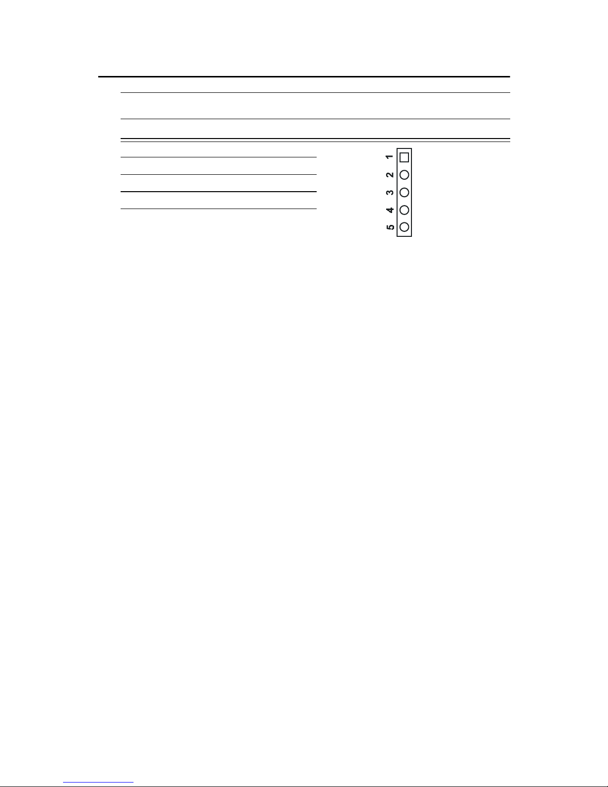
C.8 IR Connector (CN8)
Table C.8: IR Connector (CN8)
Pin Signal
1 VCC (+5 V)
2N.C.
3 IR receive
4GND
5 IR transmit
91 Appx. C
Page 100
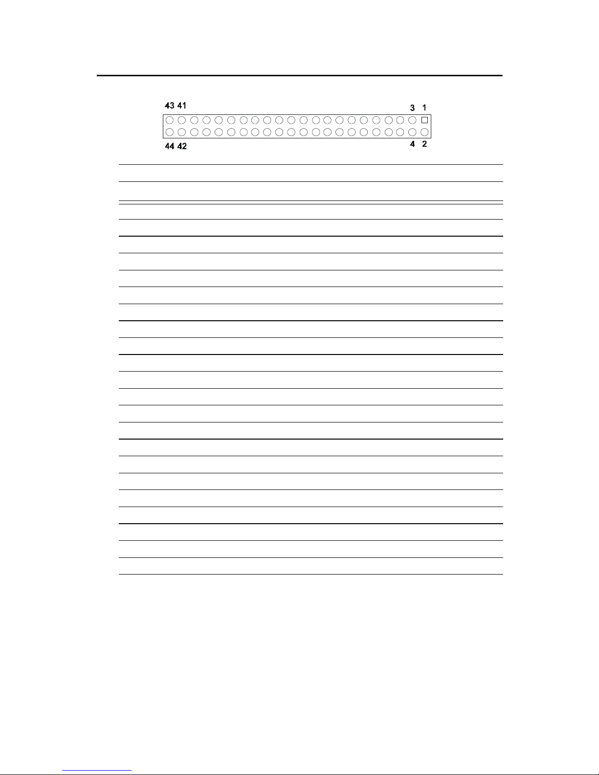
C.9 IDE Hard Drive Connector (CN9)
Table C.9: IDE HDD connector (CN9)
Pin Signal Pin Signal
1 IDE RESET* 2 GND
3DATA 7 4DATA 8
5DATA 6 6DATA 9
7DATA 5 8DATA 10
9 DATA 4 10 D ATA 11
11 DATA 3 12 DATA 12
13 DATA 2 14 DATA 13
15 DATA 1 16 DATA 14
17 DATA 0 18 DATA 15
19 SIGNAL GND 20 N/C
21 HDD 0 22 GND
23 IO WRITE 24 GND
25 IO READ 26 GND
27 HD READY 28 N/C
29 HDACK 0* 30 GND
31 IRQ14 32 N/C
33 ADDR 1 34 N/C
35 ADDR 0 36 ADDR 2
37 HARD DISK SELECT 0* 38 HARD DISK SELECT 1*
39 IDE ACTIVE* 40 GND
41 VCC 42 VCC
43 GND 44 N/C
* low active
PCM-9340 User’s Manual 92
 Loading...