

Page 1

PCM-53E52
SC520 Half EBX PC
User Manual
Rev 0.1.0
Page 2

Contents
PCM-53E52 _________________________________________________________________________________ 1
Contents____________________________________________________________________________________ 2
Introduction _________________________________________________________________________________ 3
Features ____________________________________________________________________________________ 4
Single Board Computer ______________________________________________________________________ 4
PCD-E12 I/O Daughter Board Option___________________________________________________________ 4
PCD-E12 On-board Options __________________________________________________________________ 4
Specifications________________________________________________________________________________ 5
Standard SBC functions______________________________________________________________________ 5
PCD-E12 I/O Daughter Board (additional specifications to added) ____________________________________ 5
Mechanical and environmental ________________________________________________________________ 5
Packing List_________________________________________________________________________________ 6
Packing List for standard PCM-53E52 SBC: _____________________________________________________ 6
Packing List for standard PCD-E12 I/O daughter board _____________________________________________ 6
PCM-53E52 Configuration _____________________________________________________________________ 7
Jumper & Connector Descriptions______________________________________________________________ 7
Powering Up the PCM-53E52___________________________________________________________________ 8
Ethernet __________________________________________________________________________________ 9
Serial Ports _________________________________________________________________________________ 9
Keyboard/Mouse __________________________________________________________________________ 10
Disk-On-Chip Flash Disk _____________________________________________________________________ 10
Parallel port ______________________________________________________________________________ 10
IDE connector ____________________________________________________________________________ 10
Floppy Drive connector_____________________________________________________________________ 10
Changing the CMOS without Video _____________________________________________________________ 13
Appendix A ________________________________________________________________________________ 14
Connector Pinouts ___________________________________________________________________________ 14
Com 1 DB9 Connector (CN1) ________________________________________________________________ 14
Com 2 DB9 Connector (CN2) ________________________________________________________________ 14
(RS232 Mode) (RS422/485)_______________________________________________________________ 14
Header Pinouts______________________________________________________________________________ 15
JTAG Interface (HDR1) ____________________________________________________________________ 15
IDE Connector (HDR2)_____________________________________________________________________ 15
Printer Port (HDR3)________________________________________________________________________ 15
COM4 (HDR4) ___________________________________________________________________________ 16
Floppy drive (HDR5)_______________________________________________________________________ 16
Power Connector (HDR6) ___________________________________________________________________ 16
Com 3 (HDR7) ___________________________________________________________________________ 17
Jack Pinouts________________________________________________________________________________ 17
Ethernet (JK1) ____________________________________________________________________________ 17
Keyboard/Mouse (JK2) _____________________________________________________________________ 17
Appendix B ________________________________________________________________________________ 18
Dimensional Drawing ______________________________________________________________________ 18
Page 3

Introduction
The PCM-53E52 is a compact Half-EBX board with PC/104Plus, SSD, Ethernet, and four COM ports.
Unlike other compact Half-EBX boards, the PCM-53E52 has an optional Analog and Digital I/O Daughter
Board, allowing for data acquisition and greater flexibility.
The PCM-53E52 features a low power AMD® ELAN-SC520 133Mhz processor (no fan required, P120
equiv.). This compact Half-EBX board has on board, 16MB of SDRAM memory standard. A 32MB to
128MB memory upgrade option is also available as is a DiskOnChip® 2000 (DOC) solid state flash disk
(no moving parts). The PCM-53E52 can be connected onto a network using the Realtek® RTL8139C
10/100Base-T Ethernet controller and onboard RJ-45 connector. In addition, the PC/104Plus connectors
provide both ISA and PCI connectivity.
The PCM-53E52 offers three RS-232 serial ports, one RS-232/422/485 serial port, and a parallel port that
supports SPP/EPP/ECP parallel modes. This board includes a mini-DIN keyboard/mouse connector, an
onboard 34-pin FDD interface that supports two floppy disk drives, and an onboard 44-pin EIDE interface
that supports two EIDE devices. The PCM-53E52 is 5.75" in length and 4" wide, making it a great fit for
harsh environment and limited-space applications.
The optional Analog and Digital I/O Daughter Board adds micro-controller capability with the power of a
PC. The I/O daughter board includes 16, General Purpose I/O lines and eight high current sink outputs on
a standard I/O Rack compatible 50 pin header. This board also includes: 16 channels of A/D with 10
or12-bit resolution, and four channels of D/A with 12-bit resolution. In addition, the I/O daughter board
supports up to a 24-key keypad and is capable of driving up to a 40 x 4 character and graphic LCD
displays.
Page 4

Features
Single Board Computer
• Compact size (145 mm x 102 mm). Fits in the space of a 3½ “ HDD
• ISA and PCI bus expansion with onboard PC/104Plus connector
• Onboard ELAN SC520 133MHz embedded microprocessor
• Supports M-Systems’ DiskOnChip® 2000 Flash memory
• Onboard 10/100 Base-T Ethernet interface
• Supports onboard 16MB SDRAM memory
• Onboard mini-DIN PS/2 keyboard/ mouse connector
• Built-in Enhanced IDE hard disk drive interface, floppy disk interface and parallel port
• Four serial ports: three RS-232 and one RS-422/485; on-board DB-9 connector is designated
as COM1
• Single +5 V power supply
• Flexible OEM/ODM design
PCD-E12 I/O Daughter Board Option
• 16 Channels of 10 bit A/D, 0 to 5 volt.
• 24 Digital I/O lines with 8 high drive outs.
• 1 RS232 port with handshake (1 in/1 out).
• 1 CAN 2.0B port.
• 24 Key, keypad interface (4x6 matrix).
• 8 bit Character/Graphic or 4 bit Character LCD interface.
• Status LED.
PCD-E12 On-board Options
• 8 Channels of 12 bit A/D, 0 to 5 volt replaces 8 channels of 10 bit.
• 4 Channels of 12 bit D/A, 0 to 5 volt.
Page 5

Specifications
Standard SBC functions
• CPU: Onboard ELAN SC520 133MHz embedded microprocessor
• BIOS: General Software
• RAM: Onboard 16MB SDRAM standard and 32MB to 128MB options
• Enhanced IDE HDD interface: Supports up to two Enhanced IDE devices.
• FDD interface: Supports up to two FDDs
- 5.25" (360KB and 1.2MB) and/or
- 3.5" (720KB, 1.44MB, and 2.88MB)
• Parallel port: One parallel port supports SPP/EPP/ECP parallel modes
• Serial ports: Three RS-232 ports, one RS-422/485 port
• PC/104Plus expansion: 16-bit and 32-bit PC/104 module connectors
• Keyboard/mouse connector: Mini-DIN connector for keyboard and PS/2 mouse
Solid State Disk
• Supports DiskOnChip® 2000: up to 288 MB Flash memory
Ethernet interface
• Ethernet chipset: Realtek RTL8139C
• Ethernet type: 10/100Base-T Ethernet controller
• Ethernet connection: On-board RJ-45 connector
PCD-E12 I/O Daughter Board (additional specifications to added)
• 16 Channels of 10 bit A/D, 0 to 5 volt.
• 24 Digital I/O lines with 8 high drive outs.
• 1 RS232 port with handshake (1 in/1 out).
• 1 CAN 2.0B port.
• 24 Key, keypad interface (4x6 matrix).
• 8 bit Character/Graphic or 4 bit Character LCD interface.
• Status LED.
• Optional 8 Channels of 12 bit A/D, 0 to 5 volt which replaces 8 channels of 10 bit.
• Optional 4 Channels of 12 bit D/A, 0 to 5 volt.
Mechanical and environmental
• Dimensions: 145mm x 102mm
• Weight: 0.17kg (0.37lbs)
• Power Supply Voltage: +5V (4.57 ~ 5.25V)
• Power Requirements: +5V @ 1.0 A (typical)
• Operating Temperature: 0 ~ 60° C (32 ~ 140° F)
Page 6

Packing List
Packing List for standard PCM-53E52 SBC:
1 PCM-53E52 SBC Board
1 IDE cable – 18” 40 pin cable
2 Serial header Cables – 10 pin female header to male DB9
1 Parallel port cable – 26 pin female header to male DB25
1 Standard floppy cable – 34 pin cable with 3 connectors 34 pin connectors
The following cable is optional:
Keyboard/Mouse PS/2 Y cable {This cable is required to have access to the PS/2 mouse port.}
Packing List for standard PCD-E12 I/O daughter board
1 PCD-E12 I/O daughter board
Page 7
PCM-53E52 Configuration
Jumper & Connector Descriptions
The PCM-53E52 comes factory configured and ready to operate. In the event that jumpers need to be
verified or modified this section provides the information required, including instructions on setting
jumpers and connecting peripherals, switches and indicators. Be sure to read all the safety precautions
before you begin any configuration procedure. See Appendix A for connector pin-outs and Appendix B for
Jumper Settings.
Table 1 Jumpers
Label Function
JP1 Processor Run Mode
JP2 AMD Debug Mode
JP3 Battery
JP4 Com2 Mode
Table 2 Connectors
Label Function
CN1 Com 1
CN2 Com 2
Table 3 Headers
Label Function
HDR1 JTAG Interface
HDR2 40 Pin IDE header
HDR3 Printer Port
HDR4 Com 4
HDR5 Floppy drive connector
HDR6 Power
HDR7 Com 3
Table 4 Jacks
Label Function
JK1 Ethernet interface
JK2 Keyboard/Mouse
Table 5 Sockets
Label Function
SOK1 BIOS chip holder
SOK2 DOC Socket
Table 6 LEDs
Label Function
LD1 Hard Drive Activity
LD2 Ethernet Link & Activity
LD3 Power LED
Page 8

Determining Board Configuration
The board number can be used to determine what options are populated.
For example:
PCM-53E52-0011 is a board with 16mb of ram, Ethernet and PC/104+
This is found by decoding the last 4 numbers as follows:
0XXX is the standard 16mb of onboard memory
1XXX is the upgrade to 32mb of onboard memory
2XXX is the upgrade to 64Mb of onboard memory
X0XX is a reserved designator
XX0X is the Ethernet option designator, 1 for no Ethernet, 0 if present.
XXX0 is the designator for PC104+, 1 means the PC104+ connector has not been populated.
Determining How Much Memory is Onboard
The following information is to help assist in calculating how much ram your board has on it.
This information pertains to the onboard chips U4 and U5:
16meg system =2pcs of (8mB) 4 Meg x 16 Quad bank, 3.3V-- MT48LC4M16A2TG-75
32meg system =2pcs of (16mB) 8 Meg x 16 Quad bank, 3.3V-- MT48LC8M16A2TG-75
64meg system =2pcs of (32mB) 16 Meg x 16 Quad bank, 3.3V-- MT48LC16M16A2TG-75
These part numbers are Micron Technology parts and may be substituted with equivalent chips by
another manufacturer.
If you have any questions about the configuration of the board you have please email:
Page 9

Powering Up the PCM-53E52
The PCM-53E52’s power connector (CN1) is a standard floppy, four-pin type connector commonly found
on most PC type power supplies. The PCM-53E52’s logic only requires 5 volts DC. The 12v pin (HDR6
pin 4) is routed to the PC/104 connectors and may be used by some PC/104 expansion cards. The pinout for the HDR6 power connector is as follows:
Pin Signal
1 +5 V
2 GND
3 GND
4 +12 V
Remember before powering-up the PCM-53E52 make sure the DOC is correctly orientated, firmly
seated and check any cables to make sure that plugged on and correctly in relation to pin 1.
Note: The PCM-53E52 requires less than 2 amps which is not enough current to load the main switcher
in some larger PC power supplies (this can be verified with a voltmeter measuring the 5-volt supply). If
this is the case you can try to load the power supply by adding 5-volt devices, or order a compatible
power supply from EMAC.
Ethernet
The PCM-53E52 utilizes the RTL 8139 10/100 BaseTX full duplex Ethernet chip and terminates to a
standard RJ-45 connector (JK1). It can be connected straight to a Hub, Switch or directly to another
computer via a crossover Ethernet cable. Link and Activity (Rx/Tx) LEDs (LD2) are provided to monitor
network activity.
Serial Ports
The PCM-53E52 is equipped with four serial ports. All four serial ports are standard X86, 16550, 16 byte
FIFO UARTS.
COM1 is set to be RS232 and is configured by default to 3F8H using IRQ 4. Availability is via the DB9
(CN1) connector on the edge of the board.
COM2 is jumper configurable to run RS232 or RS422/485 and is set by default to I/O address 2F8H using
IRQ 3. This comport is available via a DB9 connector (CN2). The mode is switched using JP4, if the
jumper is present it will run RS422/485.
COM3 and COM4 are both configured as RS232 ports. These are available to the user on connectors
HDR7 & HDR5 respectively. The default I/O address and IRQ for COM3 is 3E8H using IRQ 5 and the
default I/O address for COM4 is 2E8H using IRQ 11.
NOTE: COM4 DOES NOT OFFER HANDSHAKING AND IS LIMITED TO RXD AND TXD DUE TO PIN
FUNCTION TRADEOFFS AT THE SUPER I/O CHIP. SELECT FUNCTIONS FROM COM3 AND COM4
SHARED THRU ONE INTERFACE DRIVER CHIP.
Page 10

Keyboard/Mouse
The PCM-53E52 is equipped with a keyboard and mouse interface. Both the keyboard and the mouse
utilize the same PS/2 connector (JK1) through the use of the included Y cable. Though a standard PS/2
keyboard can be plugged directly into the connector, to be able to use both a keyboard and mouse you
must use the Y adapter cable or a serial mouse.
Disk-On-Chip Flash Disk
The PCM-53E52 does not come with a DOC flash drive chip installed by default, but one can be ordered
from EMAC and installed by the user or integrated at the time the PCM-53E52 is ordered.
The DOC is a solid state flash disk and as such is extremely rugged when compared to a conventional
hard drive. The DOC is a paged memory device and is mapped at segment address D000 Hex, and by
use of the device’s firmware emulates a hard drive. Thus most operating systems will be able use the
device similar to a hard drive.
Warning: Be extremely careful when installing the DOC into its socket. Plugging
it in backwards, and turning on power, can destroy the DOC and damage the
PCM-53E52 rendering both inoperable! Any information on the DOC will be
unrecoverable at this point.
Always double-check the orientation of the DOC when it has been removed from
the board and reinserted, prior to turning the power back on.
Parallel port
The PCM-53E52 comes with a Standard Parallel port interface, This is available to the user via a 26-pin
header (HDR3) and included female DB25 cable.
IDE connector
The PCM-53E52 is equipped with a standard IDE interface available to the user via the standard 40-pin
header (HDR2) on the board. A standard hard drive cable is included.
Floppy Drive connector
The PCM-53E52 is equipped to operate a standard 3.5” 1.44Mb floppy drive via the standard 34-Pin
header (HDR5). A standard floppy drive cable is included.
Page 11

PCM-53E52 BIOS Defaults
The PCM-53E52 uses a General Software BIOS. To enter the CMOS you must press the <Del> key when
prompted. The following CMOS screen shots indicate the CMOS options and the default factory values of
each option. Note: These factory set options should not require changing.
+------------------------------------------------------------------------------+
| |
| System Bios Setup - Utility v4.3 |
| (C) 2000 General Software, Inc. All rights reserved |
+------------------------------------------------------------------------------+
| |
| |
| |
| |
| |
| >Basic CMOS Configuration |
| Custom Configuration |
| Shadow Configuration |
| Reset CMOS to last known values |
| Reset CMOS to factory defaults |
| Write to CMOS and Exit |
| Exit without changing CMOS |
| |
| |
| |
| |
| |
+------------------------------------------------------------------------------+
| <Esc> to continue (no save) |
www.gensw.com
+------------------------------------------------------------------------------+
| |
| System Bios Setup - Basic CMOS Configuration |
| (C) 2000 General Software, Inc. All rights reserved |
+---------------------------+--------------------+-----------------------------+
| DRIVE ASSIGNMENT ORDER: | Date:>Jun 18, 2002 | Typematic Delay : 250 ms |
| Drive A: Floppy 0 | Time: 19 : 38 : 16 | Typematic Rate : 30 cps |
| Drive B: (None) | NumLock: Disabled | Seek at Boot : None |
| Drive C: (None) +--------------------+ Show "Hit Del" : Enabled |
| Drive D: (None) | BOOT ORDER: | Config Box : Enabled |
| Drive E: (None) | Boot 1st: Drive A: | F1 Error Wait : Disabled |
| Drive F: (None) | Boot 2nd: Drive C: | Parity Checking : (Unused) |
| Drive G: (None) | Boot 3rd: (None) | Memory Test Tick : Disabled |
| Drive H: (None) | Boot 4th: (None) | Test Above 1 MB : Enabled |
| Drive I: (None) | Boot 5th: (None) | Debug Breakpoints: Disabled |
| Drive J: (None) | Boot 6th: (None) | Splash Screen : Disabled |
| Drive K: (None) +--------------------+-----------------+-----------+
| Boot Method: Boot Sector | IDE DRIVE GEOMETRY: Sect Hds Cyls | Memory |
+---------------------------+ Ide 0: 3 = AUTOCONFIG, LBA | Base: |
| FLOPPY DRIVE TYPES: | Ide 1: Not installed | 640KB |
| Floppy 0: 1.44 MB, 3.5" | Ide 2: Not installed | Ext: |
| Floppy 1: 1.44 MB, 3.5" | Ide 3: Not installed | 31MB |
+---------------------------+--------------------------------------+-----------+
| ^E/^X/<Tab> to select or +/- to modify |
<Esc> to return to main menu
Page 12

+------------------------------------------------------------------------------+
| |
| System BIOS Setup - Custom Configuration |
| (C) 2000 General Software, Inc. All rights reserved |
+---------------------------------------+--------------------------------------+
| IR Mode :>Disabled | IR Port Location/IRQ : 3E8h/4 |
| ECC Memory : Disabled | SDRAM Device Timing : Fast |
| Write Buffer : Disabled | Cache Mode : Write-Through |
| CPU speed : 133 MHz | |
| | |
| | |
| | |
| | |
| | |
| | |
| | |
| | |
| | |
| | |
| | |
| | |
| | |
+---------------------------------------+--------------------------------------+
| ^E/^X/<Tab> to select or +/- to modify |
<Esc> to return to main menu
+------------------------------------------------------------------------------+
| |
| System BIOS Setup - Shadow/Cache Configuration |
| (C) 2000 General Software, Inc. All rights reserved |
+---------------------------------------+--------------------------------------+
| Shadowing :>Chipset | Shadow 16KB ROM at C000 : Enabled |
| Shadow 16KB ROM at C400 : Enabled | Shadow 16KB ROM at C800 : Enabled |
| Shadow 16KB ROM at CC00 : Enabled | Shadow 16KB ROM at D000 : Disabled |
| Shadow 16KB ROM at D400 : Disabled | Shadow 16KB ROM at D800 : Disabled |
| Shadow 16KB ROM at DC00 : Disabled | Shadow 16KB ROM at E000 : Enabled |
| Shadow 16KB ROM at E400 : Enabled | Shadow 16KB ROM at E800 : Enabled |
| Shadow 16KB ROM at EC00 : Enabled | Shadow 64KB ROM at F000 : Enabled |
| | |
| | |
| | |
| | |
| | |
| | |
| | |
| | |
| | |
| | |
+---------------------------------------+--------------------------------------+
| ^E/^X/<Tab> to select or +/- to modify |
<Esc> to return to main menu
Page 13

Changing the CMOS without Video
When running the board (Headless) without video, to enter the CMOS configuration you will need to plug
in a keyboard, and a null modem serial cable to COM1. The CMOS configuration will then be redirected
to the COM1 comport after pressing the delete key on the keyboard. This is done by pressing delete on
the keyboard just after the keyboard lights flash (after keyboard initialization) and before the BIOS beep,
following the board being powered up or reset. The CMOS configuration will be sent out COM1 at 9600
baud, 8 bits, no parity, one stop bit (9600-8-N-1).
Changes then can be made via HyperTerminal or any other serial terminal program.
Needed commands are:
CTRL-e Move Up
CTRL-x Move Down
TAB Move Right
+ Toggle Selection Up
- Toggle Selection Down
ENTER Goto Selected Menu
ESC Return to Main Menu/ Exit Without Saving
If a video card is present, hitting the delete key will take you directly into the BIOS setup screen and no
serial port redirection will take place.
Page 14

Appendix A
Connector Pinouts
Com 1 DB9 Connector (CN1)
Pin DB9 Description
1 DCD
2 RxD
3 TxD
4 DTR
5 GND
6 DSR
7 RTS
8 CTS
9 RI
Com 2 DB9 Connector (CN2)
(RS232 Mode) (RS422/485)
Pin DB9 Description
1 DCD
2 RxD 2 TRANS +
3 TxD 3 TRANS 4 DTR
5 GND
6 DSR
7 RTS 7 REC +
8 CTS 8 REC 9 RI
Page 15

Header Pinouts
JTAG Interface (HDR1)
Pin Signal Pin Signal
1 GND 2 PWR GOOD
3 JTAG_TCK 4 CMDACK
5 JTAG_TMS 6 BR/TC
7 JTAG_TDI_1 8 STOP/TX
9 JTAG_TDO_MPU 10 TRIG/TRACE
11 -SRESET 12 N.C.
IDE Connector (HDR2)
Pin Signal Pin Signal
1 Reset 2 GND
3 D7 4 D8
5 D6 6 D9
7 D5 8 D10
9 D4 10 D11
11 D3 12 D12
13 D2 14 D13
15 D1 16 D14
17 D0 18 D15
19 GND 20 N.C.
21 N.C. 22 GND
23 I OW 24 GND
25 IOR 26 GND
27 IORDY 28 BALE
29 N.C. 30 GND
31 IRQ 14 32 -I/O CS16
33 A1 34 N.C.
35 A0 36 A2
37 CS0 38 CS1
39 -ACT 40 GND
Printer Port (HDR3)
Pin Signal Pin Signal
1 \STROBE 2 \AUTOFD
3 D0 4 ERR
5 D1 6 \INIT
7 D2 8 \SLCTINI
9 D3 10 GND
11 D4 12 GND
13 D5 14 GND
15 D6 16 GND
17 D7 18 GND
19 \ACK 20 GND
21 BUSY 22 GND
23 PE 24 GND
25 SLCT 26 N/C
Page 16

COM4 (HDR4)
Pin Signal DB9 Description
1 NC 2 NC RxD
3 RxD TxD
4 NC 5 TxD GND
6 NC 7 NC 8 NC 9 GND 10 NC --
Floppy drive (HDR5)
Pin Signal Pin Signal
1 GND 2 DENSITY SELECT
3 GND 4 N/C
5 GND 6 N/C
7 GND 8 INDEX
9 GND 10 MOTOR 0
11 GND 12 DRIVE SELECT 1
13 GND 14 DRIVE SELECT 0
15 GND 16 MOTOR 1
17 GND 18 DIRECTION
19 GND 20 STEP
21 GND 22 WRITE DATA
23 GND 24 WRITE GATE
25 GND 26 TRACK 0
27 GND 28 WRITE PROTECT
29 GND 30 READ DATA
31 GND 32 HEAD SELECT
33 GND 34 DISK CHANGE
Power Connector (HDR6)
Pin Signal
1 +5 V
2 GND
3 GND
4 +12 V
Page 17

Com 3 (HDR7)
Pin Signal DB9 Description
1 DCD DCD
2 DSR RxD
3 RxD TxD
4 RTS DTR
5 TxD GND
6 CTS DSR
7 DTR RTS
8 NC CTS
9 GND -10 NC --
Jack Pinouts
Ethernet (JK1)
Pin Signal
1 XMT+
2 XMT3 RCV+
4 N/C
5 N/C
6 RCV7 N/C
8 N/C
Keyboard/Mouse (JK2)
Pin Signal
1 KB DATA
2 MS DATA
3 GND
4 VCC
5 KB CLOCK
6 MS CLOCK
Page 18
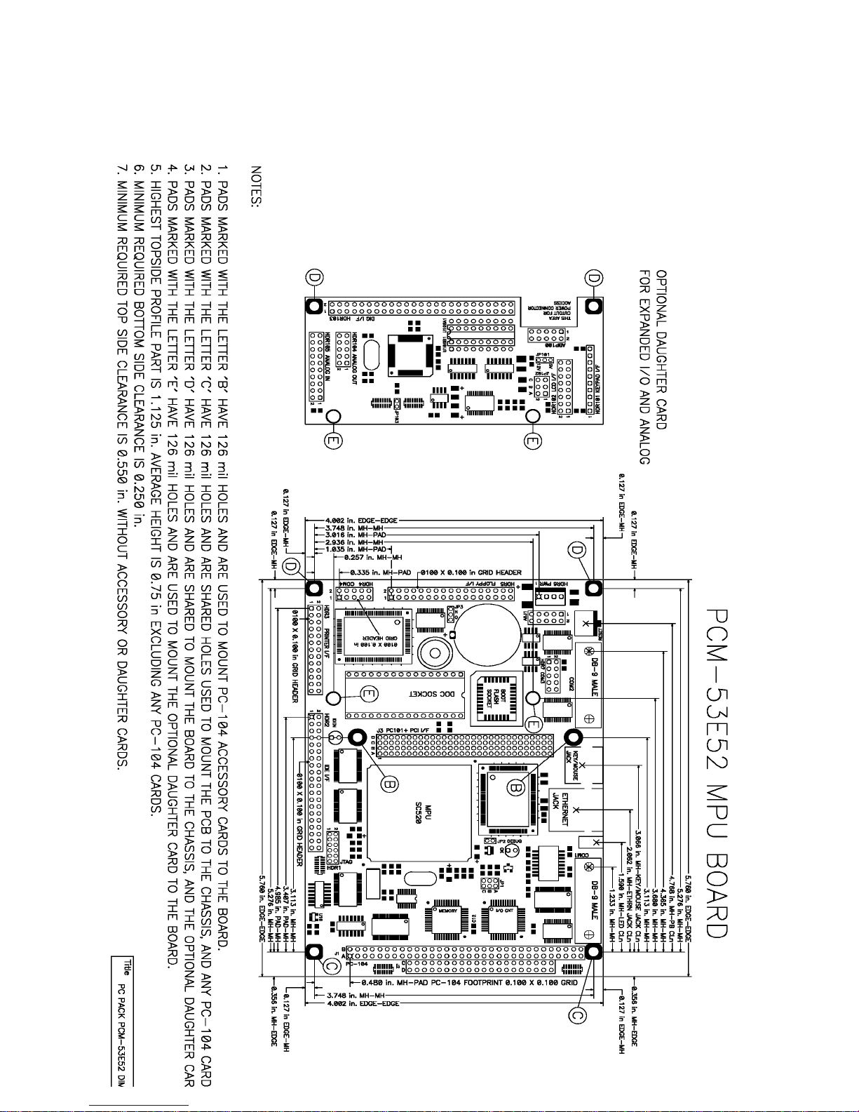
Appendix B
Dimensional Drawing
 Loading...