

Page 1

PCM-4896
All-in-One NS Geode GX1 Single
Board computer with LCD,
Ethernet, Audio, & 4 COMs
Page 2

FCC STATEMENT
THIS DEVICE COMPLIES WITH PAR T 15 FCC RULES. OPERA-
TION IS SUBJECT TO THE FOLLOWING TWO CONDITIONS:
(1) THIS DEVICE MA Y NOT CAUSE HARMFUL INTERFERENCE. (2) THIS DEVICE MUST ACCEPT ANY INTERFERENCE
RECEIVED INCLUDING INTERFERENCE THA T MA Y CAUSE
UNDESIRED OPERA TION.
THIS EQUIPMENT HAS BEEN TESTED AND FOUND TO
COMPL Y WITH THE LIMITS FOR A CLASS "A" DIGITAL
DEVICE, PURSUANT TO PAR T 15 OF THE FCC RULES.
THESE LIMITS ARE DESIGNED TO PROVIDE REASONABLE
PROTECTION AGAINTST HARMFUL INTERFERENCE WHEN
THE EQUIPMENT IS OPERA TED IN A COMMERCIAL ENVIRONMENT . THIS EQUIPMENT GENERATES, USES, AND
CAN RADIA TE RADIO FREQUENCY ENERGY AND , IF NOT
INST A TLLED AND USED IN ACCORDANCE WITH THE INSTRUCTION MANUAL, MA Y CAUSE HARMFUL INTERFERENCE TO RADIO COMMUNICATIONS. OPERATION OF
THIS EQUIPMENT IN A RESIDENTIAL AREA IS LIKEL Y TO
CAUSE HARMFUL INTERFERENCE IN WHICH CASE THE
USER WILL BE REQUIRED TO CORRECT THE INTERFERENCE A T HIS OWN EXPENSE.
Page 3

Copyright Notice
This document is copyrighted, 1999. All rights are reserved. The original manufacturer reserves the right to make improvements to the
products described in this manual at any time without notice.
No part of this manual may be reproduced, copied, translated, or
transmitted in any form or by any means without the prior written
permission of the original manufacturer . Information provided in this
manual is intended to be accurate and reliable. However, the original
manufacturer assumes no responsibility for its use, nor for any infringements upon the rights of third parties which may result from its
use.
Acknowledgements
AMD is a trademark of Advanced Micro Devices, Inc.
AMI is a trademark of American Megatrends, Inc.
A ward is a trademark of Award Software International, Inc.
Cyrix is a trademark of Cyrix Corporation.
IBM, PC/A T , PS/2, and VGA are trademarks of International
Business Machines Corporation.
Intel and Pentium II are trademarks of Intel Corporation.
Microsoft Windows® is a registered trademark of Microsoft Corp.
SMC is a trademark of Standard Microsystems Corporation.
R TL is a trademark of Realtek Semi-Conductor Co., Ltd.
C&T is a trademark of Chips and T echnologies, Inc.
UMC is a trademark of United Microelectronics Corporation.
ITE is a trademark of Integrated T echnology Express, Inc.
SiS is a trademark of Silicon Integrated Systems Corp.
VIA is a trademark of VIA T echnology , Inc.
All other product names or trademarks are properties of their
respective owners.
Manual PCM-4896 9th Edition
Prepared in Taiwan May. 2002
Page 4

A Message to the Customer
EMAC Customer Services
Each and every EMAC's product is built to meet your exact needs
and specifications to ensure excellent performance in the harsh and
demanding conditions which is typical of the industrial environments.
Whether the new EMAC equipment is designed for the laboratory or
the factory floor, you can be assured that the product will provide the
reliability and ease of operation for which the name EMAC has
come to be known.
Your satisfaction is our primary concern, and here is a guide of the
services for EMAC's customers. To get the full benefit of our
services, please follow the instructions below carefully.
Technical Support
We hope you can get the outstanding performance from our products.
So if you run into technical difficulties, we are here to help. For the
most frequently asked questions, you can easily find answers in
your product documentation. These answers are normally much
more detailed than the ones we can provide over the phone.
So please consult this manual first. If you still cannot find the
answer, gather all the information or questions that apply to your
problem, and with the product close at hand, call your dealer. Our
dealers are well trained and ready to give you the support you need
to get the most from your EMAC products. In fact, most problems
reported are minor and could be easily solved over the phone.
In addition, professional technical support is available from EMAC's
engineers every business day. We are always ready to give advice
on application requirements or specific information on the installation and operation of any of our products.
Page 5

Product Warranty
EMAC warrants to you, the original purchaser, that each of its
products will be free from defects in materials and workmanship for
two years from the date of purchase.
This warranty does not apply to any products which have been
repaired or modified by unauthorized personnel, or those products
which have been misused, abused, installed improperly and altered
accidentally. EMAC assumes no liability under the terms of this
warranty as a consequence of such events.
Because of EMAC's high quality-control standards and rigorous
testing, most of our customers never need to use our repair service.
If an EMAC's product is defective, it will be repaired or replaced with
no charge during the warranty period. For out-of-warranty repairs,
you will be billed according to the cost of replacement materials,
service time, and freight. Please consult your dealer for more
details.
If you think you have received a defective product, follow these steps:
1 . Collect all the information about the problem encountered. (For
example, CPU type and speed, EMAC products used, other
hardware and software used, etc.) Note anything abnormal and
list any on-screen messages you get when the problem occurs.
2. Please prepare your manual, product, and other helpful information
before calling your dealer to describe your problem.
3. If your product is diagnosed as defective, please manage to obtain
an RMA (return material authorization) number from your dealer.
This allows us to deal with your return quickly.
4. Carefully pack the defective product, a fully-completed Repair
and Replacement Order Card, and a photocopy proof of purchase date (such as your sales receipt) in a shippable container.
A product returned without the proof of the purchase date is not
eligible for warranty service.
5. Write the RMA number visibly on the outside of the package
and ship it out after paying to your dealer for it.
Page 6

Packing list
Before you begin installing your card, please make sure that the following materials have been shipped:
• 1 PCM-4896 All-in-One Single Board Computer
• 1 Quick Installation Guide
• 1 CD-ROM contains the followings:
-- User's Manual (this manual in PDF file)
-- Ethernet drivers and utilities
-- VGA drivers and utilities
-- Audio drivers and utilities
-- Latest BIOS (as of the CD-ROM was made)
The PCM-4896 require several cables for operation. You can make
them yourself or pruchase an optioanl cable kit, PCM-10489-5
If any of these items are missing or damaged, contact your distribuitor or sales representative immediately .
Page 7

Notice
Dear Customer,
Thank you for purchasing the PCM-4896 board. This user's man-
ual is designed to help you to get the most out of the PCM-4896,
please read it thoroughly before you install and use the board. The
product that you have purchased comes with an two-year limited
warranty, but EMAC will not be responsible for misuse of the product. Therefore, we strongly urge you to first read the manual before
using the product.
Page 8

Contents
Chapter 1: General Information.........................................1
Introduction....................................................................2
Features..........................................................................3
Specifications..................................................................4
Board layout....................................................................7
Board dimensions...........................................................8
Chapter 2: Installation ........................................................9
Jumpers and connectors...............................................10
Locating jumpers...........................................................12
Locating connectors......................................................13
Setting jumpers.............................................................14
CPU installing and upgrading.......................................15
Installing DRAM (DIMMs).........................................16
Internal buzzer select (J1)............................................17
Clear CMOS (J4)..........................................................17
ATX Soft-Power Switch connector (J5)........................17
Audio output select (J6)...............................................18
CD audio connector (J7)...............................................18
LCD driving voltage select (J8)...................................19
LCD clock signal select (J9)........................................19
COM3/COM4 RI pin voltage select (J12, J11)...........20
COM2 RS-232/422/485 select (J13, J14)....................21
SW1 (1~3) Cpu frequency ratio....................................22
SW2 (1) CPU clock select............................................22
GX1 CPU jumper setting examples.............................23
DOC address select SW1 (5, 6)....................................24
Power connectors (PW1, J3)........................................25
ATX power connector (PW1)............................................25
CPU fan power connector (J3)..........................................25
USB connector (CN2)...................................................26
Page 9

IDE hard drive connector (CN4)..................................27
Connecting the hard drive.................................................27
IDE hard drive connector (CN4).......................................28
Front Panel connector (CN5)........................................29
IrDA connector (CN6)..................................................30
Display connectors (CN7, CN9)...................................31
VGA display connector (CN9)..........................................31
LCD connector (CN7).....................................................32
Keyboard and mouse connector (CN8)........................33
Audio connector (CN10)...............................................34
Parallel port connector (CN11).....................................35
Parallel port IRQ..............................................................35
Parallel port connector table (CN11)..................................35
100Base-Tx Ethernet connector (CN12).....................36
Digital I/O connector (CN15).......................................36
Serial ports (CN13).......................................................37
COM 1-4 RS-232/422/485 serial ports (CN13)...................37
Floppy drive connector (CN14)....................................38
Connecting the floppy drive...............................................38
Floppy drive connector (CN14)..........................................39
Ethernet LED signal connectors (LED1).....................40
DiskOnChip socket (U4)..............................................41
DiskOnChip (DOC) 2000 Installation..........................42
Chapter 3: Award BIOS Setup .........................................43
Starting setup ...............................................................44
Setup keys.....................................................................45
Getting help...................................................................46
In case of problem............................................................46
Main setup menu..........................................................47
Standard CMOS setup..................................................49
BIOS features setup ........................................................... 56
Page 10

CHIPSET features setup..............................................61
Power management setup.............................................63
PNP/PCI congfiguration setup......................................66
Load BIOS defaults/Load setup defaults......................68
Integrated peripherals setup........................................69
Supervisor/User password setting ...............................72
IDE HDD auto detection..............................................74
Save & exit setup.........................................................75
Exit without saving.........................................................76
Chapter 4: C&T 69000 Flat Panel/CRT controller Display
Drivers and Utilities ..................................77
Software drives..............................................................78
Hardware configuration.....................................................78
Necessary prerequisites....................................................79
Before you begin..............................................................79
Windows 95/98..............................................................80
Driver installation.............................................................80
Windows 3.1..................................................................86
Driver installation.............................................................86
OS/2...............................................................................87
Windows NT 3.51..........................................................89
Driver installation.............................................................89
Windows NT 4.0............................................................90
Driver installation.............................................................90
Chapter 5: Ethernet Software configuration .....................
.....................................................................93
Win9X/NT Ethernet Installation...................................92
Ethernet Software Configuration..................................93
Page 11

Chapter 6: Audio setup.....................................................95
Introduction...................................................................96
Setting up in windows 95/98..........................................96
Installing the drivers under Window 95/98...........................97
Appendix A: Programming the Watchdog Timer ..........105
Programming the watchdog timer .............................106
How to program the WATCHDOG TIMER......................106
Demo program................................................................107
Appendix B: Installing PC/104 Modules........................109
Installing PC/104 modules..........................................110
Appendix C: Optional Extras ......................................... 113
PCM-10489-5 Wiring Kit............................................114
Optional USB Cable ...................................................115
Page 12

Page 13

Chapter 1 General Information 1
1
General
Information
This chapter gives background information on the mainboard.
Sections include:
• Board specifications
• Layout and dimensions
CHAPTER
Page 14

2 PCM-4896 User Manual
Introduction
The PCM-4896 is an all-in-one multi-media NS Geode GX1 MMX processor based single board computer (SBC) with an integrated audio
controller, a PCI Flat Panel controller , a PCI 100Base-Tx Ethernet interface, and one PCI expansion slot. With ture Pentium MMX capability ,
the PCM-4896 achieves outstanding performance that surpasses other
SBC in its class. In addition, the onboard SSD interface supports Msystems DiskOnChip 2000 series, memory capacity from 2 MB to 288
MB. This compact (only 5.75"“ x 8") unit offers all the functions of a
single board industrial computer, but still fits in the space of a CDROM drive.
On-board features include four serial ports (three RS-232, one RS232/422/485), one multi-mode parallel (ECP/EPP/SPP) port, connector
for two USB (Universal Serial Bus) ports, a floppy drive controller,
and a keyboard/PS/2 mouse interface. The built-in high speed PCI
IDE controller supports Ultra DMA/33 mode. Up to two IDE devices
can be connected, including large hard disks, CD-ROM drives, and
tape backup drives, etc.
The PCM-4896 also features power management to minimize power
consumption. It complies with the APM standard and supports three
types of power saving features: Doze mode, Standby mode, and Suspend mode. In addition, the board's watchdog timer can be programed
to reset the system or generate an interrupt in case the system stops
due to a program bug or EMI.
Highly integrated multi-media SBC
The PCM-4896 is a highly integrated multi-media SBC that combines
audio, video, and network functions on a CD-ROM drive size single
computer board. It provides, 16-bit full-duplex, integrated 3D audio
and up to 1024 x 768 resolution @ 64K colors with on-chip 2MB
SDRAM display memory . Major onboard devices adopt PCI technology to achieve outstanding computing performance.
Page 15

Chapter 1 General Information 3
Features
• Supports NS Geode GX1 BGA CPU up to 300 MHz
• Support Disk On Chip up to 288MB
• C&T 69000 LCD controller support 36-bit TFT panels
• 100Base-Tx Ethernet interface, supports Remote Boot ROM function.
• AC-97 2.0 audio interface, Sound Blaster compatible
• Supports Bus Master and Ultra DMA/33 IDE devices
• Three RS-232 and one RS-232/422/485 serial ports
• USB interface, PCI slot, and PC/104 connector for flexible expansion
capabilities
Page 16

4 PCM-4896 User Manual
Specifications
Standard SBC Functions
• CPU: NS Geode GX1 BGA CPU up to 300MHz
• BIOS: A ward 256KB Flash BIOS
• Chipset: NS CS5530A
• I/O Chipset: NS97317/ITE IT8661F . Fully 16-bit I/O decoded
• Cache: Processor build-in 16KB Level-1 write-back cache
• Memory: Onboard one 168-pin DIMM socket supports up to
256Mbytes SDRAM
• Enhanced IDE: Support up to two IDE devices. Supports Ultra DMA/
33 mode with data transfer rate up to 33MB/sec.
• FDD interface: Supports up to two floppy disk drives, 5.25" (360KB
and 1.2MB) and /or 3.5" (720KB, 1.44MB, and 2.88MB)
• Parallel port: One bi-directional parallel port. Supports SPP , ECP and
EPP modes
• Serial ports: Three RS-232 and one RS-232/422/485 serial ports.
Ports can be configured as COM1, COM2, COM3, COM4,
or disabled individually . (16C550 equivalent)
• IR interface: Supports one IrDA Tx/Rx header
• Keyboard/mouse connector: 8 pin connector supports PC/A T
keyboard and PS/2 mouse
• USB connectors: 4 x 2 header onboard supports dual USB ports
• Battery: Lithium battery for data retention of up to 10 years
• Watchdog Timer: Can generate a system reset.
Support software selectable timeout interval.
• DMA: 7 DMA channels (8237 equivalent)
• Interrupt: 15 interrupt levels (8259 equivalent)
Page 17

Chapter 1 General Information 5
• Power management: Supports A TX power supply . Supports PC97,
, and modem ring-in functions. I/O peripheral
devices support power saving and doze/
standby/suspend modes.
Flat Panel/CRT Interface
• Chipset: C&T 69000
• Display memory: Built-in 2MB SDRAM
• Display type: Supports non-interlaced CRT and LCD 36-bit TFT/STN/
Mono displays. Can display both CR T and Flat Panel
simultaneously
• Resolution: Up to 1280x1024 256 color for CRT
Up to 1024x768 for Flat Panel.
Sound Interface
• Chipset: NS CS5530A
• 3D audio: Supports for Microsoft DirectSound and DirectSound 3D audio
technology in two-speaker mode (requires Microsoft Direct Sound
3D supported software titles)
• 16-bit stereo digital audio: Full-duplex support enables simultaneous-
record and playback for Internet communications software
Ethernet interface
• Chipset: Reltek RTL8139C 100Base-Tx Fast Ethernet controller
• Ethernet interface: 100Base-Tx RJ-45 connector. Optional Remote
Boot ROM function
Page 18

6 PCM-4896 User Manual
SSD Interface
One 32-pin DIP socket supports M-systems DiskOnChip up to 288 MB
Expansion Slots
• PC/104 connector: One 16-bit 104-pin connector onboard
• PCI slot: One 32-bit PCI slot onboard
Mechanical and environmental
• Power supply voltage: +5V (4.75V to 5.25V),
+12V (11.4V to 12.6V)
• Typical power r equirement: +5V@3A
• Operating temperature: 32 to 140o F (0 to 60o C)
• Board size: 8"(L) x 5.75"(W) (203mm x 146mm)
• Weight: 1.2 lb. (0.5 Kg)
Page 19
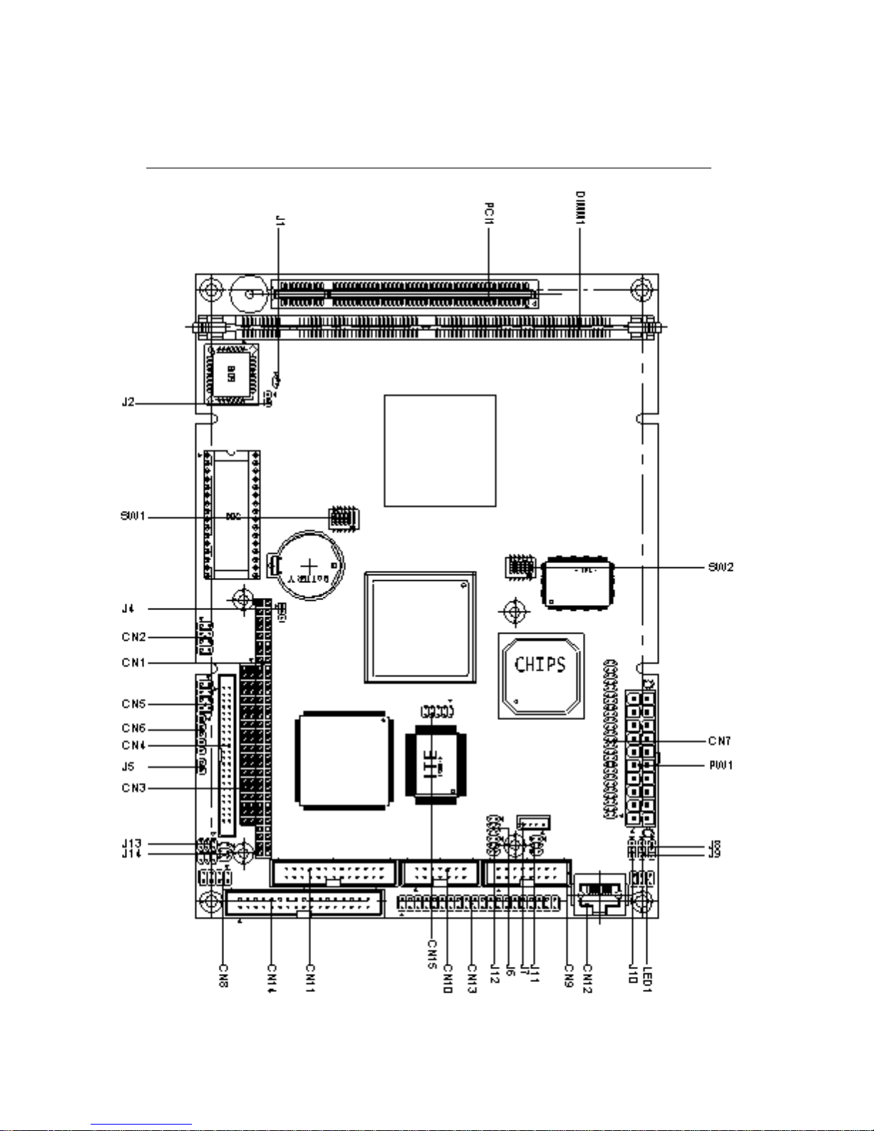
Chapter 1 General Information 7
Board Layout
PCM-4896
Page 20
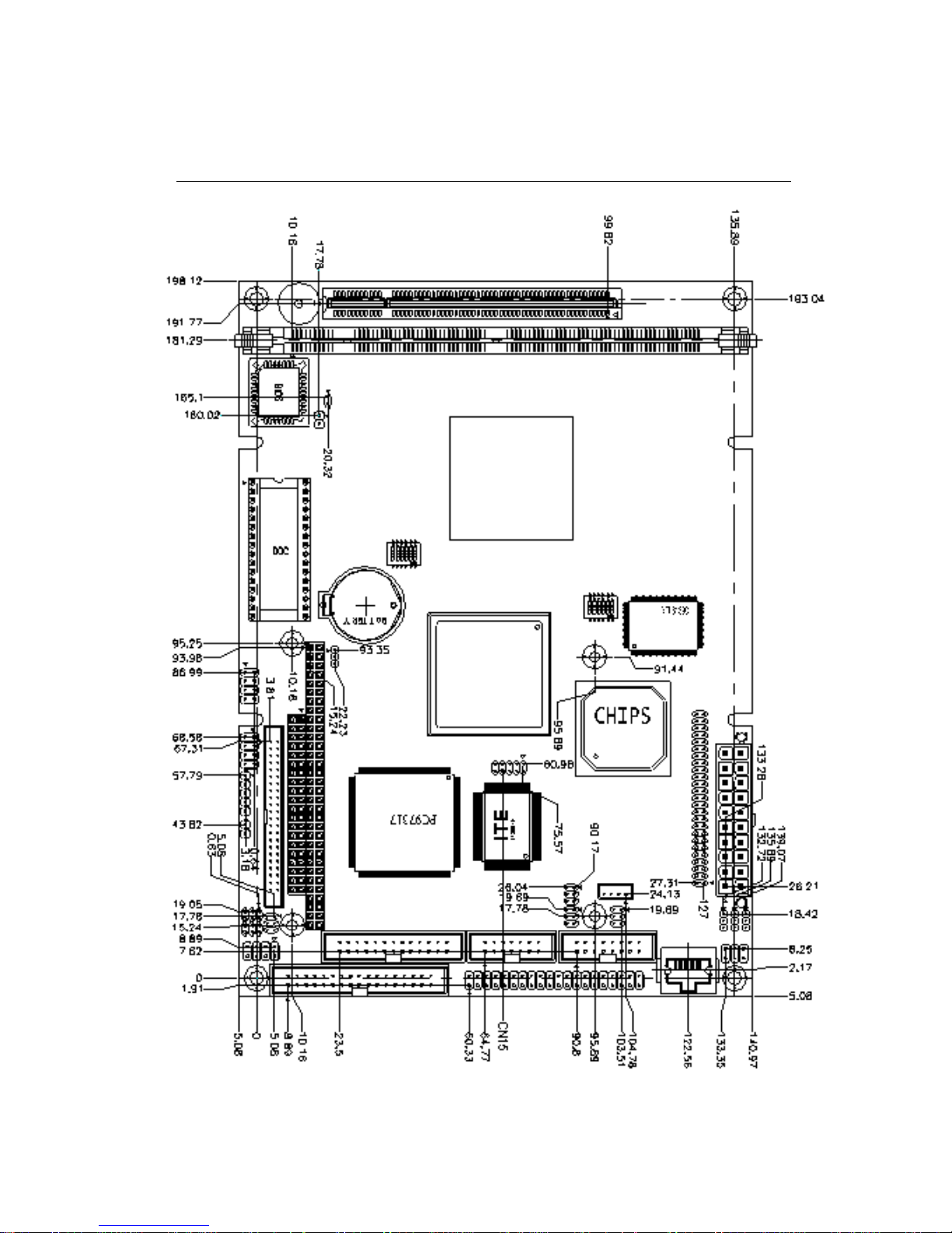
8 PCM-4896 User Manual
Board Dimensions
PCM-4896 dimensions
dimensions in mm
Page 21

Chapter 2 Installation 9
2
Installation
This chapter describes how to set up the
main board hardware, including instructions
on setting jumpers and connecting peripherals, switches, and indicators. Be sure to
read all the safety precautions before you
begin the installation procedure.
CHAPTER
Page 22

10 PCM-4896 User Manual
Jumpers and Connectors
Connectors on the board link themselves to the external devices
such as hard disk drives, a keyboard, or floppy drives. In addition,
the board has a number of jumpers that allow you to configure your
system to suit your application.
The following tables list the function of each jumper and connector
on the board.
Jumpers
Label Function
J1 Internal buzzer select
J4 Clear CMOS
J5 ATX soft-power switch connector
J6 Audio output select
J8 LCD driving voltage select
J9 LCD clock select
J1 0 Audio Power (default: 1-2 close)
J11 COM4 RI pin voltage select
J1 2 COM3 RI pin voltage select
J13 COM2 RS232/422/485 setting
J14 COM2 RS232/422/485 selection
SW1 (1~3) CPU frequency ratio
SW1 (5, 6) DOC address select
SW2 (1) CPU clock select
Page 23

Chapter 2 Installation 11
Connectors
Label Function
CN1 PC/104 connector
CN 2 USB ports connector
CN 4 IDE drive connector
CN 5 Front panel connector
CN6 IrDA connector
CN7 LCD display connector
CN 8 Keyboard and PS/2 mouse connector
CN9 VGA display connector
CN10 Audio connector
CN 11 Printer port connector
CN12 100Base-Tx Ethernet connector
CN13 Serial ports connector
CN14 Floppy dirve connector
CN15 Digital I/O connector
PW1 ATX power connector
J7 CD-ROM signal input connector
LED1 Ethernet Tx/Rx/Link LED connector
U4 DiskOnChip socket
Page 24
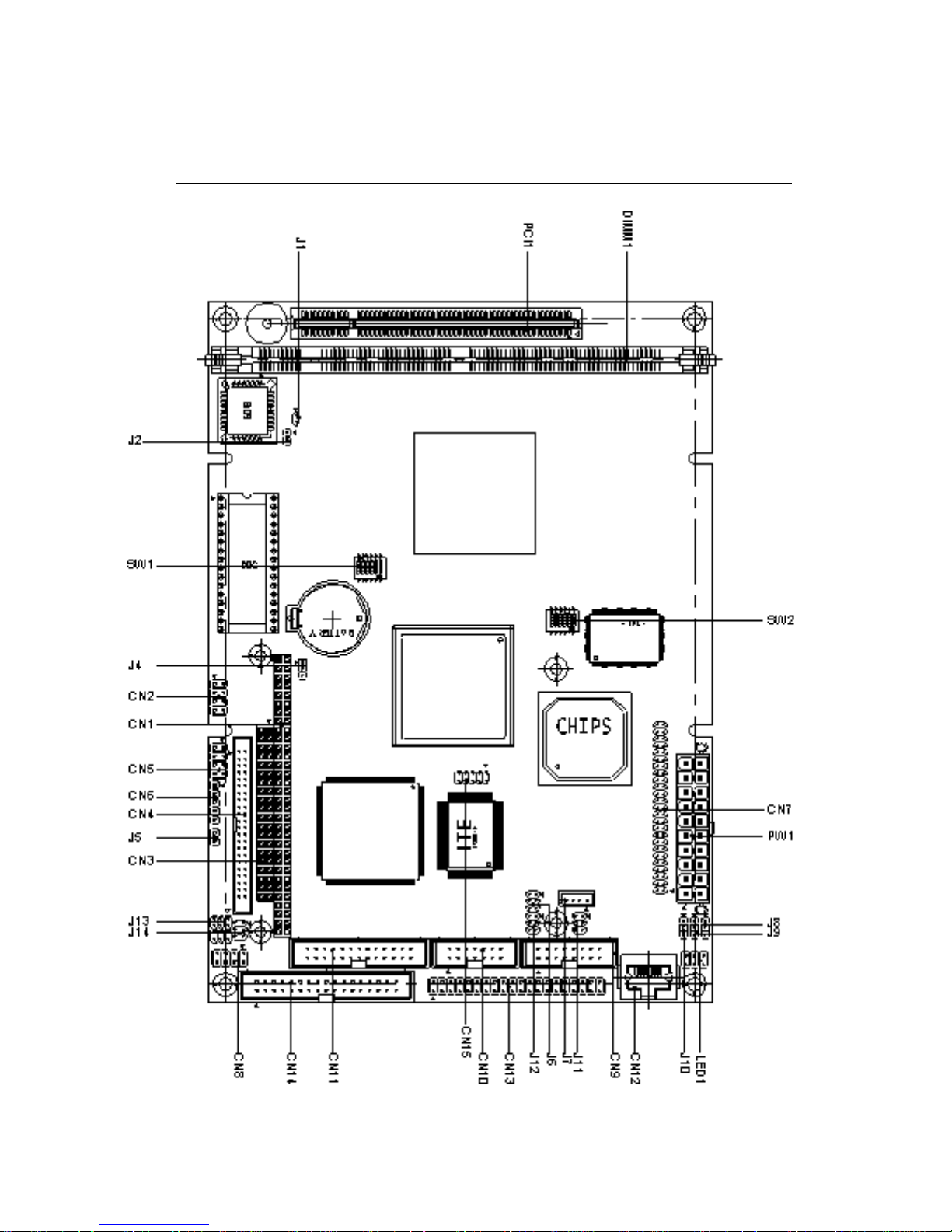
12 PCM-4896 User Manual
Locating Jumpers and Connectors
Page 25
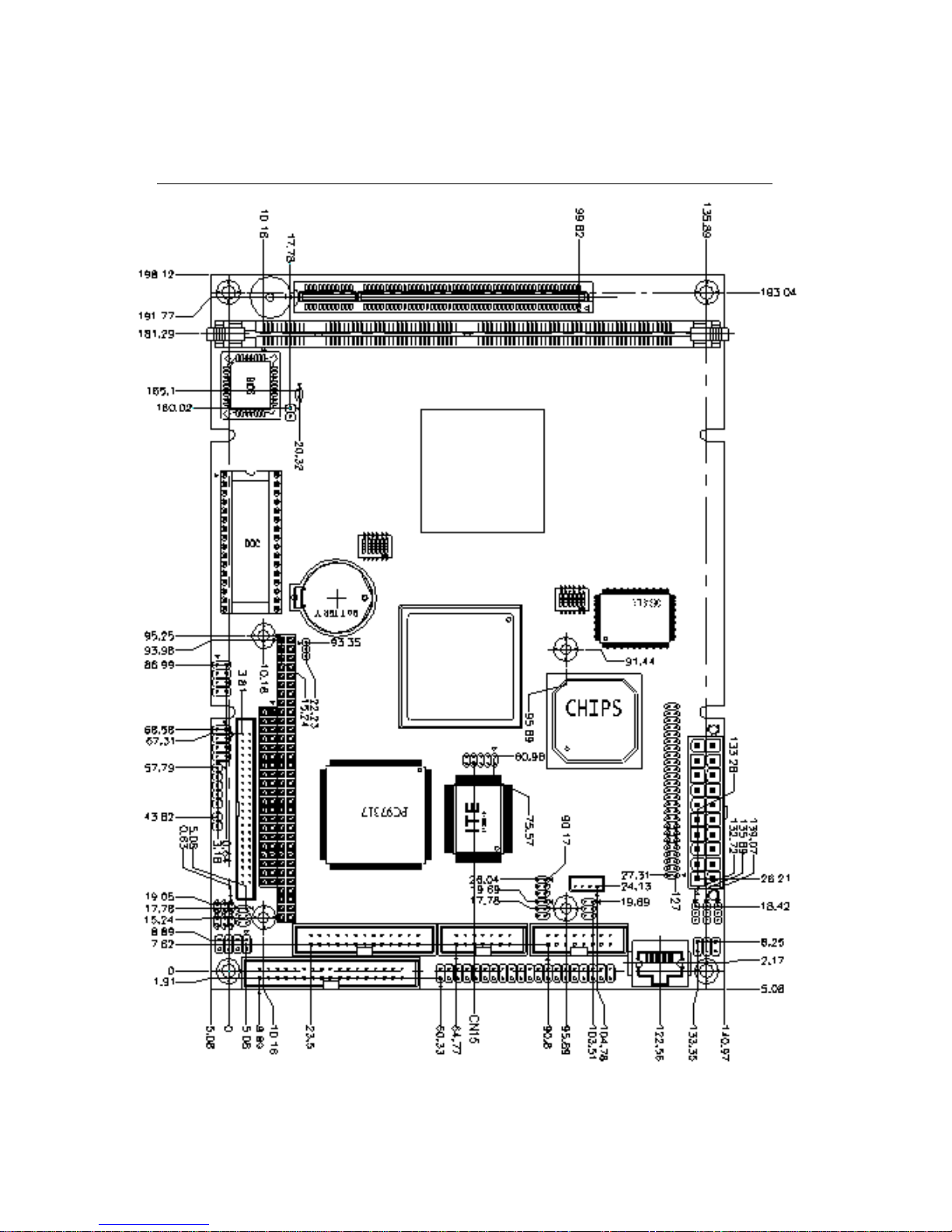
Chapter 2 Installation 13
Mechanical Drawing
Page 26
14 PCM-4896 User Manual
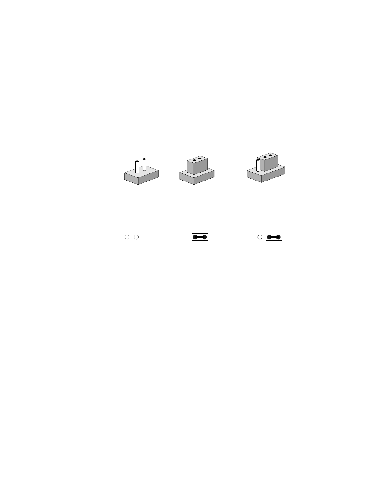
Setting Jumpers
You can configure your card to match the needs of your applications
by setting jumpers. A jumper is the simplest kind of electric switch. It
consists of two metal pins and a small metal clip (often protected by
a plastic cover) that slides over the pins to connect them. T o c lose an
jumper you can connect the pins with the clip. T o open an jumper you
can remove the clip. Sometimes a jumper will have three pins, labeled
1, 2, and 3. In this case you would connect either pins 1 and 2 or 2 and
3.
The jumper settings are schematically depicted in this manual as follows:
A pair of needle-nose pliers may be helpful when working with jumpers.
If you have any doubts about the best hardware configuration for
your application, contact your local distributor or sales representative before you make any changes.
Open Closed Closed 2-3
1
3
2
Open Closed Closed 2-3
1 2 3
Page 27
Chapter 2 Installation 15
Installing and Upgrading CPU
BGA type CPU for PCM-4896 C1.0 series is installed and all related
setting were done in factory. Please do not attempt to change any
CPU setting, this may cause an un-expected damage to this board.
Warning! Always disconnect the power cord from your
chassis when you are working on it. Do not make
connections while the power is on as sensitive
electronic components can be damaged by the
sudden rush of power. Only experienced electronics personnel should open the PC chassis.
Caution! Always ground yourself to remove any static
charge before touching the PC board. Modern
electronic devices are very sensitive to static
electric charges. Use a grounding wrist strap at
all times. Place all electronic components on a
static-dissipative surface or in a static-shielded
bag when they are not in the chassis.
Any CPU related setting change is prohibited, Improper settings
may damage the CPU.
Page 28
16 PCM-4896 User Manual
Installing DRAM (DIMMs)
System Memory
The left edge of the PCM-4896 C1.0 contains a socket for 168-pin dual
inline memory module (DIMM). The socket uses 3.3 V unbuffered
synchronous DRAM (SDRAM). DIMM is available in capacities of
16, 32, 64, or 128 MB. The socket can be filled in the DIMM of any
size, giving your PCM-4896 single board computer between 16 and
128 MB of memory .
Supplementary Information About DIMM
Your PCM-4896 C1.0 can accept both regular and PC-100 SDRAM
DIMM Module(with or without parity).
Single-sided modules are typically 16 or 64 MB; double-sided modules are usually 32 or 128 MB.
Memory Installation Procedures
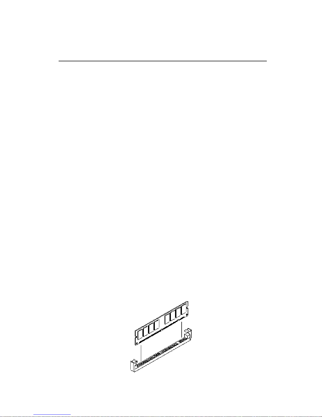
T o install DIMM, first make sure the two handles of the DIMM socket are in the "open" position. i.e. The handles remain outward. Slowly
slide the DIMM module along the plastic guides on both ends of the
socket. Then press the DIMM module right down into the socket,
until you hear a click. This is when the two handles have automatically locked the memory module into the correct position of the DIMM
socket. (See Figure below) To take away the memory module, just
push both handles outward, and the memory module will be ejected
by the mechanism in the socket.
Page 29
Chapter 2 Installation 17
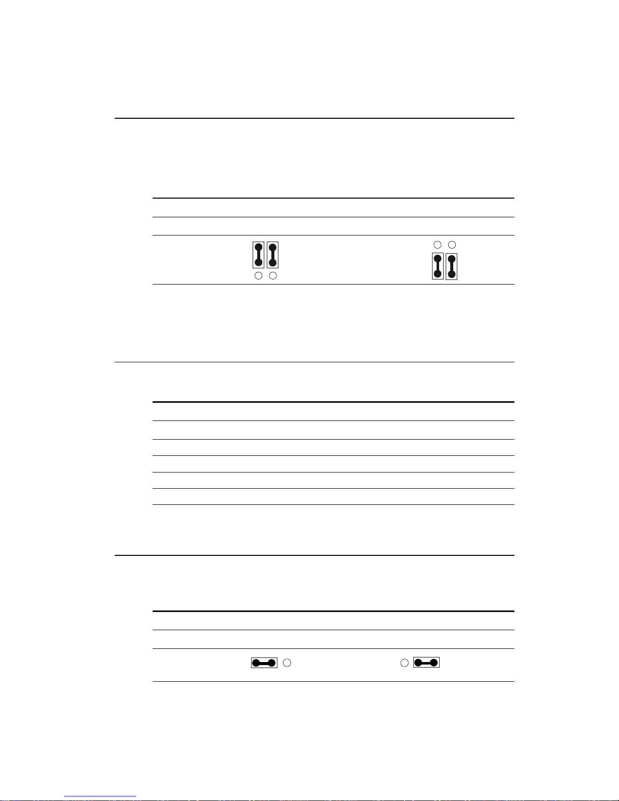
Internal Buzzer Select (J1)
Internal Buzzer Select (J1)
Internal Buzzer External Speaker
Clear CMOS (J4)
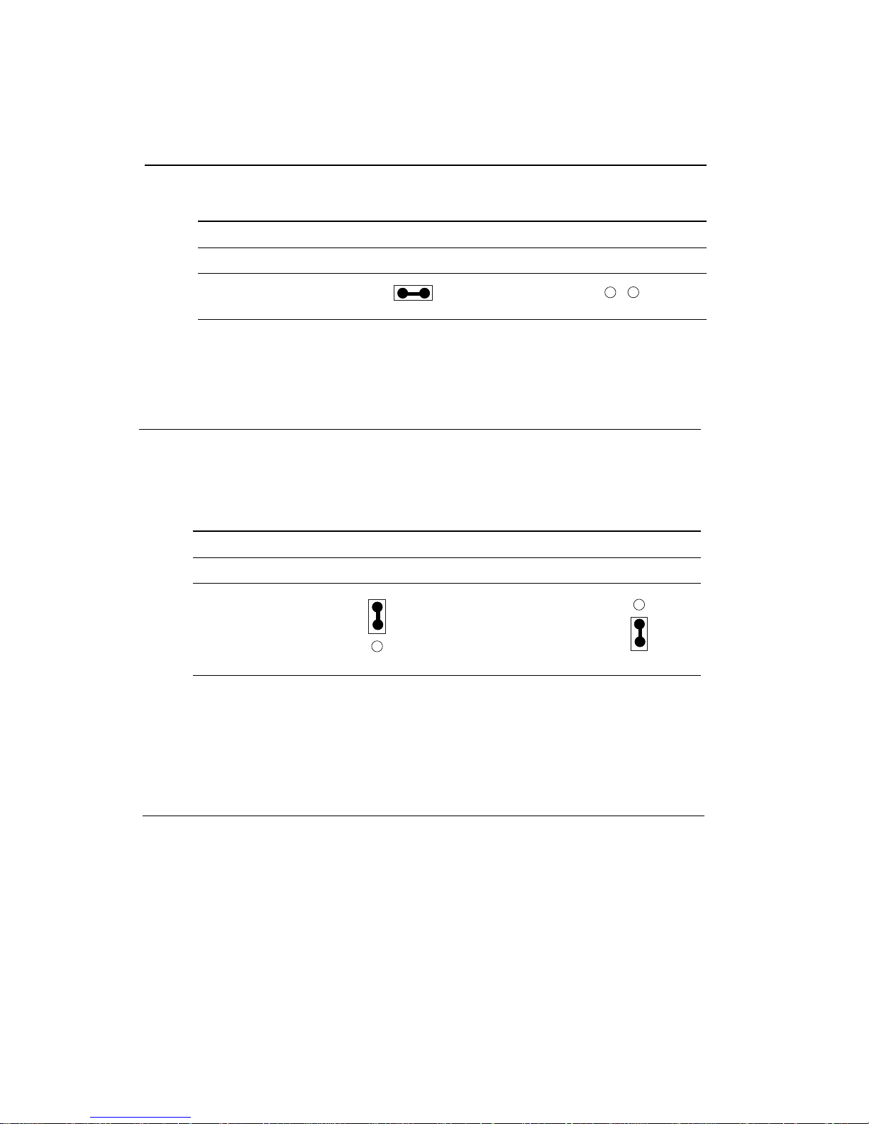
You can use J4 to clear the CMOS data if necessary. To reset the
CMOS data, set J4 to pin 2-3 closed for just a few seconds, and then
move the jumper back to pin 1-2 closed.
Clear CMOS (J4)
Protect* Clear CMOS
J4
*default
1
2
3
1
2
3
ATX Soft-Power Switch Connector (J5)
The A TX Soft-Power switch connector is a 2-pin header . Please plug
the power switch cable from your system to the Soft-Power switch
connector marked J5.
J1
1 2
1 2
Page 30
18 PCM-4896 User Manual
CD Audio connector (J7)
This connector is used to connect to a CD audio cable.
CD Audio Connector (J7)
Pin Signal
1 GND
2 CD_L
3 GND
4 CD_R
J8
LCD Driving Voltage Select (J8)
You can select the LCD connector CN7 (pin 5 and pin 6) driving
voltage by setting J8. The configurations are as follows:
LCD Driving Voltage Select (J8)
5V 3.3V *
*default
1 2 3 1 2 3
2 1
4 3
6 5
2 1
4 3
6 5
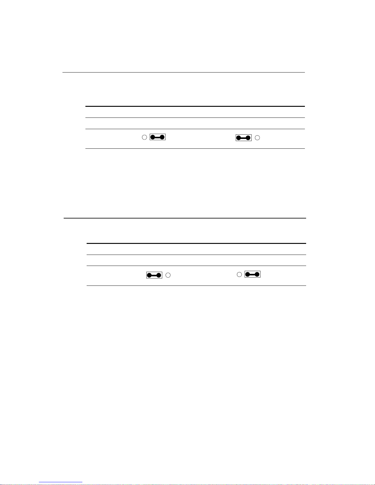
Audio Output Select (J6)
You can select the output mode of onboard audio connector (CN10)
by setting J6.
"Speaker out" is the output signal amplified by onboard amplifier
Audio Output Select (J6)
Line out* Speaker out
J6
*default
Page 31
Chapter 2 Installation 19
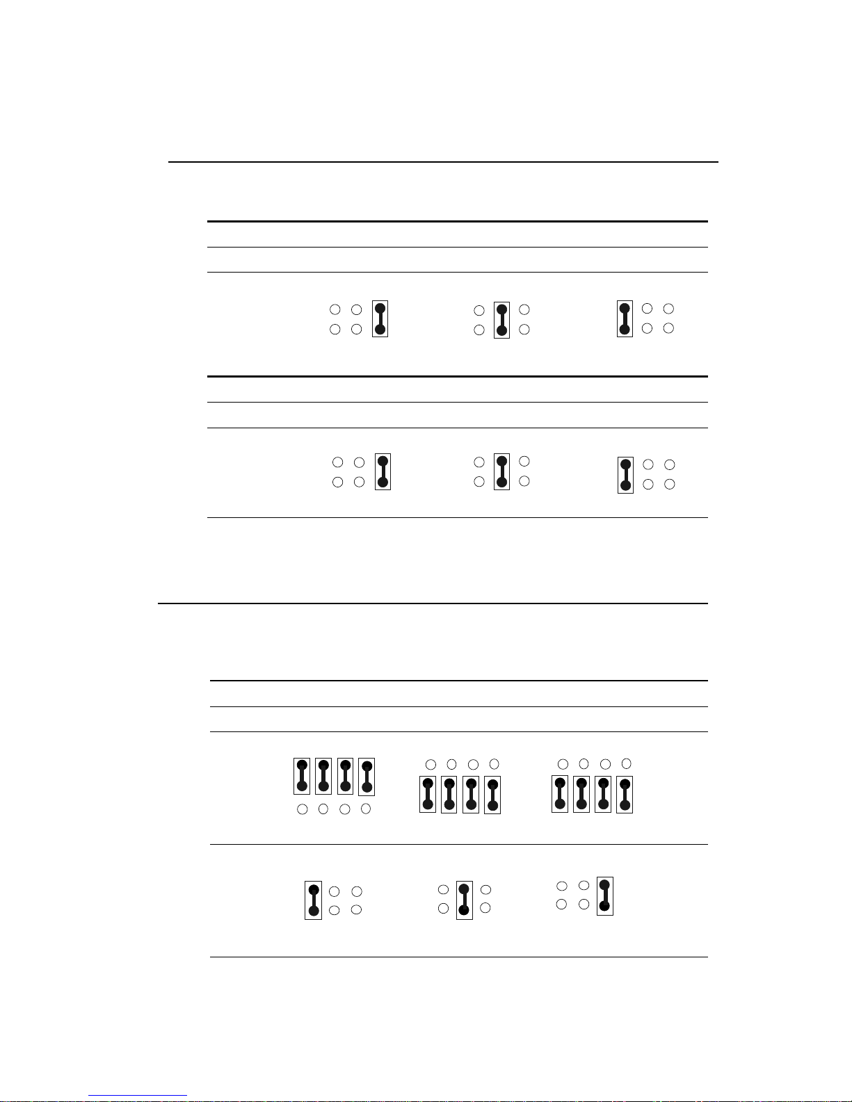
LCD Clock Signal Select (J9)
You can select the LCD control signal by setting J9. The following
chart shows the available option.
LCD Clock Signal Select (J9)
SHF CLK * ASHF CLK
*default
J9
1 2 3
1 2 3
Audio Power Setting (J10)
The default setting is pin1 and pin 2 closed to offer audio power.
Audio Power Setting (J10)
Vcc * Reserved
*default
J10
1 2 3
1 2 3
Page 32
20 PCM-4896 User Manual
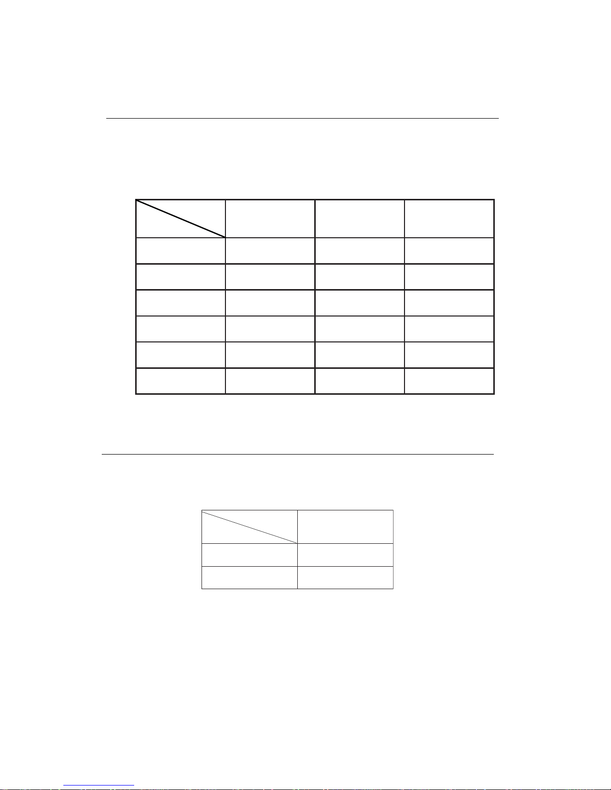
COM2 RS-232/422/485 select (J13, J14)
The PCM-4896 COM2 serial port can be selected as RS-232, RS-422,
or RS-485 by setting J13 & J14.
COM2 Select (J13, J14)
RS-232* RS-422 RS-485
J13
J14
*default
COM3 RI Pin Setting (J12)
RI* +5V +12V
J12
COM4 RI Pin Setting (J11)
RI * +5V +12V
J11
*default
COM3/COM4 RI Pin V oltage Select (J12, J11)
The 9th pin of COM3 and COM4 (9-pin D-sub connector) can be
selected as RI, +5V, or +12V by setting J12 & J1 1.
1 3 5
2 4 6
1 3 5
2 4 6
1 3 5
2 4 6
1 3 5
2 4 6
1 3 5
2 4 6
1 3 5
2 4 6
1 4 7 10
3 6 9 12
1 4 7 10
3 6 9 12
1 4 7 10
3 6 9 12
1 3 5
2 4 6
1 3 5
2 4 6
1 3 5
2 4 6
Page 33
Chapter 2 Installation 21
SW1 (1~3) CPU Frequency Ratio
SW2 (1) CPU Clock Select
Y ou can configure the CPU external clock to 33MHz or 30MHz by
setting SW2(1).
123
X4NONONO
X5NOFFOFFO
X6FFONOFFO
X7FFOFFONO
X9NOFFONO
X01NONOFFO
SW1
Ratio
1
zHM33NO
zHM03FFO
SW2
Freq.
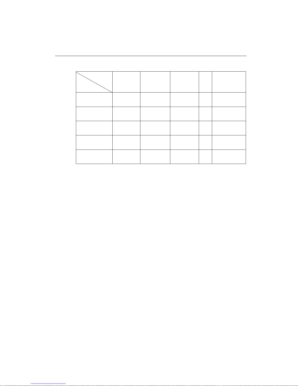
The GX1 CPU core frequency = CPU frequency ratio (4~10X) * External CPU clock (33 or 30MHz). The following table shows the available
cnfigurations.
Any CPU setting change is strongly prohibited!!
Page 34
22 PCM-4896 User Manual
GX1 CPU Jumper Setting Examples
1-1WS2-1WS3-1WS1-2WS
zHM081FFONOFFOFFO
zHM002FFONOFFONO
zHM332FFOFFONONO
zHM662NOFFONOFFO
zHM003NONOFFOFFO
SW
CPU
Any CPU setting change is strongly prohibited!!
Page 35

Chapter 2 Installation 23
DOC Address Select SW1 (5,6)
The DiskOnChip 2000 occupies an 8 K byte window in the upper
memory address range of D400 to E000. Y ou should ensure this does
not conflict with any other device's memory address.
The configuration are as follows:
These addresses might conflict with the ROM BIOS of other peripheral boards. Please select the appropriate memory address to avoid
memory conflicts.
56
elbasiDNONO
004DFFOFFO
008DNOFFO
00CDFFONO
SW1
Address
Page 36

24 PCM-4896 User Manual
Power Connectors (PW1, J3)
ATX Power Connector (PW1)
The ATX power supply uses a 20-pin connector shown as below.
Please make sure you plug in the right direction.
ATX power connector (PW1)
Pin Signal Pin Signal
1 N/C 11 N/C
2 N/C 12 -12V
3 GND 13 GND
4 +5V 14 PON
5 GND 15 G N D
6 +5 V 16 GND
7 GND 17 G N D
8 N/C 18 -5V
9 5V SB 19 +5V
10 +12V 20 +5V
Page 37

Chapter 2 Installation 25
USB Connector (CN2)
The PCM-4896 C1.0 provides two USB (Universal Serial Bus) interfaces, which give complete plug and play , hot attach/detach for up to
127 external devices. The USB interfaces comply with USB specification Rev . 1.0, and can be disabled in the system BIOS setup.
PCM-4896 C1.0
USB Connector (CN2)
Pin Function Pin Function
1 GND 5 Vcc
2 UD1+ 6 UD03 UD1- 7 UD0+
4 Vcc 8 GND
Page 38

26 PCM-4896 User Manual
IDE Hard Drive Connector (CN4)
You can attach one or two Enhanced Integrated Device Electronics
hard disk drives to the mainboard's internal controller. The mainboard's IDE controller uses a PCI local-bus interface. This advanced
interface supports faster data transfer rate and allows the IDE hard
drive to exceed 528 MB.
Connecting the Hard Drive
Connecting drives is done in a daisy-chain fashion and requires one
of two cables, depending on the drive size. 1.8" and 2.5" drives need
a 1 x 44-pin to 2 x 44-pin flat-cable connector . 3.5" drives use a 1 x 44pin to 2 x 40-pin connector.
Wire number 1 on the cable is normally red or blue, and the other
wires are usually gray .
1. Connect one end of the cable to CN4 and make sure that the red
(or blue) wire corresponds to pin 1 on the connector, which is
labeled on the board (on the right side).
2. Plug the other end of the cable to the Enhanced IDE hard drive,
with pin 1 on the cable corresponding to pin 1 on the hard drives.
(please read your hard drive's documentation for the location of
the connector).
Connect a second drive as described above.
Unlike floppy drives, IDE hard drives can connect to either end of
the cable. If you install two drives, you will need to set one as the
master and the other as the slave by using jumpers on the drives.
If you install just one drive, set it as the master.
Page 39

Chapter 2 Installation 27
IDE hard drive connector (CN4)
IDE Hard Drive Connector (CN4)
Pin Signal Pin Signal
1 IDE RESET 2 GND
3DATA 7 4 DATA 8
5DATA 6 6 DATA 9
7DATA 5 8 DATA 10
9 DATA 4 10 DATA 11
11 DA T A 3 12 DAT A 12
13 DA T A 2 14 DAT A 13
15 DA T A 1 16 DAT A 14
17 DA T A 0 18 DAT A 15
19 SIGNAL GND 20 N/C
21 HDRQ 22 GND
23 IO WRITE 24 GND
25 IO READ 26 GND
27 IO CHANNEL READY 28 GND
29 HACK 30 GND
31 IRQ14 32 N/C
33 ADDR 1 34 N/C
35 ADDR 0 36 ADDR 2
37 HARD DISK SELECT 0 38 HARD DISK SELECT 1
39 HDLED 40 GND
41 VCC 42 VCC
43 GND 44 N/C
Page 40

28 PCM-4896 User Manual
Front Panel Connector (CN5)
Next, you may want to install external switches to monitor and control
the mainboard. These features are completely optional. Please install
them only if you need them. The front panel connector (CN5) is an 8pin male, dual in-line header and provides connections for a speaker,
hard disk access indicator, and an input switch for resetting the card.
Front Panel Connector (CN5)
Pin Signal Pin Signal
7 Reset - (GND) 8 Reset Switch
5 GND 6 NC
3 Speaker - 4 Vcc
1 HDD LED - 2 Vcc
Speaker
The mainboard can drive an 8Ω external speaker at 0.5 watts. If there
is no external speaker, the PCM-4896 C1.0 provides an on-board
buzzer as an alternative.
LED Interface
The front panel LED indicator for hard disk access is an active low
signal (24 mA sink rate).
Page 41

Chapter 2 Installation 29
IrDA connector (CN6)
The IrDA connector (CN6) can be configured to support wireless
infrared module. With this module and software such as laplink or
Win95 Direct Cable connection, user can transfer files to or from
laptops, notebooks, PDA and printers. This connector supports
HPSIR (115.2Kbps, 2 meters), ASK-IR (56Kbps) and Fast IR (4Mbps,
2 meters).
Install infrared module onto IrDA connector and enable infrared function from BIOS setup. But please make sure to have correct orientation when you plug onto IrDA connector (CN6).
IrDa Connector (CN6)
Pin Signal
1 Vcc
2 FIrRx
3 IrRx
4 GND
5 IrTx
Page 42

30 PCM-4896 User Manual
Display Connectors (CN7, CN9)
The mainboard's PCI SVGA interface can drive conventional CRT
displays and a wide range of flat panel displaysat the same time,
including electroluminescent (EL), gas plasma, passive LCD, and active LCD displays. The board has two connectors to support these
displays, one for standard CR T VGA monitors and the other for flat
panel displays.
VGA Display Connector (CN9)
CN9 is a 16-pin, dual-in-line header used for conventional CR T displays. A simple one-to-one adapter can be used to match CN9 to a
standard 15-pin D-SUB connector commonly used for VGA.
VGA Display Connector (CN9)
Pin Signal Pin Signal
1 RED 9 VCC +5V
2 GREEN 10 GND
3 BLUE 1 1 N/C
4 N/C 12 DDC DAT
5 GND 13 H-SYNC
6 GND 14 V-SYNC
7 GND 15 DDC CLK
8 GND 16 N/C
Page 43

Chapter 2 Installation 31
LCD Connector (CN7)
CN7 is a 50-pin, dual-in-line header used for flat panel displays.
When the mainboard's power is applied, the control signal is low
until the relevant flat panel signals are present.
Configuration of the VGA interface is done completely via the soft-
ware utility. So you do not have to set any jumper.
LCD Connector (CN7)
Pin Signal Pin Signal
1 +12 V
DC
2 +12 V
DC
3 GND 4 GND
5 +5 V
DC
or +3.3 V
DC
6 +5 VDCor +3.3 V
DC
7 ENA VEE 8 GND
9P0 10 P1
11 P 2 12 P 3
13 P4 14 P5
15 P6 16 P7
17 P8 18 P9
19 P10 20 P11
21 P12 22 P13
23 P14 24 P15
25 P16 26 P17
27 P18 28 P19
29 P20 30 P21
31 P22 32 P23
33 P24 34 P25
35 SHF CLK 36 FLM (V SYS)
37 M 38 LP (H SYS)
39 GND 40 ENABKL
41 P26 42 P27
43 P28 44 P29
45 P30 46 P31
47 P32 48 P33
49 P34 50 P35
Page 44

32 PCM-4896 User Manual
Keyboard and Mouse Connector (CN8)
The mainboard provides a keyboard connector which supports both
a keyboard and a PS/2 style mouse. In most cases, especially in
embedded applications, a keyboard is not used. The standard PC/A T
BIOS will report an error or fail during power-on-self-test (POST)
after a reset if the keyboard is not present. The mainboard BIOS
Advanced Setup Menu allows you to select "Present" or "Absent"
under the "System Keyboard" section. This allows no-keyboard
operation in embedded system applications without the system halting under POST .
Keyboard and Mouse Connector (CN8)
Pin Signal Pin Signal
1 KB DAT A 5 KB CLOCK
2 GND 6 V c c
3 Mouse DAT A 7 Mouse CLOCK
4 N/C 8 N/C
Page 45

Chapter 2 Installation 33
Audio Connector (CN10)
The PCM-4896 C1.0 provides all major audio signals on a 14-pin flatcable connector, CN10.
Attach the Mic In, Line In, and Audio Out to the corresponding pins
as shown in the following table.
Audio Connector (CN10)
Pin Signal Pin Signal
1 Mic In 2 Reserve for future use
3 GN D 4 Reserve for future use
5 Line In Left 6 Reserve for future use
7 Line In Right 8 Reserve for future use
9 GN D 10 Reserve for future use
11 Audio Out Left 12 Audio Out Right
13 GND_Line out 14 GND_Speaker out
CAUTION: Both Line-out and Speaker-out modes share the
same pair of Audio Out signal lines but different
grounds. In addition to setting up J6 on page
18, make sure you use the corresponding ground
signal when making the cable by yourself.
Page 46

34 PCM-4896 User Manual
Parallel Port Connector (CN11)
Normally, the parallel port is used to connect the board to a printer.
The PCM-4896 C1.0 includes an onboard parallel port, accessed
through CN11, a 26-pin flat-cable connector. You need an adapter
cable if you use a traditional DB-25 connector . The cable has a 26-pin
connector on one end and a DB-25 connector on the other.
Parallel Port IRQ
The onboard parallel port is designated as LPT1 and can be disabled
or changed to LPT2 or LPT3 in the system BIOS setup.
Parallel Port Connector Table (CN11)
Parallel Port Connector (CN11)
Pin Signal Pin Signal
1 STROBE 2 AUTOFD
3 DO 4
ERR
5 D1 6
INIT
7 D2 8
SLCTINI
9 D3 10 GND
11 D4 12 GN D
13 D5 14 GN D
15 D6 16 GN D
17 D7 18 GN D
19
ACK
20 GND
21 BUST 22 GND
23 PE 24 GND
25 SLCT 26 N/C
Page 47

Chapter 2 Installation 35
100Base-Tx Ethernet Connector (CN12)
This 100Base-Tx Ethernet connector is a standard RJ-45 connector.
The onboard Realtek R TL8139C fast Ethernet controller supports
10Mb/s and 100 Mb/s N-way auto-negotiation operation.
100Base-Tx Ethernet Connector (CN12)
Pin Signal Pi n Signal
1 Tx+ 2 Tx3 Rx+ 4 N/C
5 N/C 6 Rx7 N/C 8 N/C
Digital I/O Connector (CN15)
The PCM-4896 C1.0 has onboard 4 TTL digital input channels and 4
TTL digital output channels. The pin assignment of CN15 are as
follows and the input address is 281, while the output address is 280.
Digital I/O Connector (CN15)
Pin Signal Pi n Signal
1 DI 0 2 DI 1
3 DI 2 4 DI 3
5 DO 0 6 DO 1
7 DO 2 8 DO 3
9 Vcc 10 GND
Page 48

36 PCM-4896 User Manual
Serial ports (CN13)
The PCM-4896 C1.0 offers four serial ports, three RS-232 and one RS232/422/485. These ports allow you to connect them to serial devices
(mouse, printers, etc.).
COM 1-4 RS-232/422/485 Serial Ports (CN13)
COM1, COM2, COM3, COM4 RS-232/422/485 Serial Port
PIN SIGNAL PIN SIGNAL
COM1 1 DCDA 2 DSRA
3 RXDA 4 RTSA
5 TXDA 6 CTSA
7 DTRA 8 RIA
9 GND 10 N.C.
COM2 11 DCDB 12 DSRB
(422TXD-/485DA TA-)
13 RXDB 14 RTSB
(422RXD+)
15 TXDB 16 CTSB
(422TXD+/485DA TA+)
17 DTRB 18 RIB
(422RXD-)
19 GND 20 N.C.
COM3 21 DCDC 22 DSRC
23 RXDC 24 RTSC
25 TXDC 26 CTSC
27 DTRC 28 RIC/+5V/+12V
29 GND 30 N.C.
COM4 31 DCDD 32 RSRD
33 RXDD 34 RTSD
35 TXDD 36 CTSD
37 DTRD 38 RID/+5V/+12V
39 GND 40 N.C.
Page 49

Chapter 2 Installation 37
Floppy Drive Connector (CN14)
You can attach up to two floppy drives to the mainboard controller
and use any combination of 5.25"(360 KB and 1.2 MB) and/or 3.5"
(720 KB, 1.44 MB, and 2.88 MB) drives.
A 34-pin daisy-chain drive connector cable is required for a dualdrive system. On one end of the cable is a 34-pin flat-cable connector .
On the other end are two sets of floppy disk drive connectors. Each
set consists of a 34-pin flat-cable connector (usually used for 3.5"
drives) and a printed-circuit board connector (usually used for
5.25"drives).
Wire number 1 on the cable is normally red or blue, and the other
wires are usually gray .
Connecting the Floppy Drive
1 . Plug the 34-pin flat-cable connector into CN14 and make sure that
the red or blue wire corresponds to pin 1 on the connector.
2 . Attach the appropriate connector on the other end of the cable to
the floppy drive(s). But you can use only one connector in the
set. The set on the end (after the twist in the cable) connects to
the A: drive and the set in the middle connects to the B: drive.
3. If you are connecting a 5.25"floppy drive, line up the slot in the
printed circuit board with the blocked-off part of the cable connector.
4. If you are connecting a 3.5" floppy drive, you may have trouble
determining which pin is pin number 1. Please look for a number
printed on the circuit board indicating pin number 1. Also, the
connector on the floppy drive connector may have a slot. When
the slot is up, pin number 1 should be on the right. It would be
better to check the documentation that came with the drive for
more information.
If you desire, connect the B: drive to the connectors in the middle of
the cable as described above.
Page 50

38 PCM-4896 User Manual
Floppy Drive Connector (CN14)
Floppy Drive Connector (CN14)
Pin Signal Pin Signal
1 GND 2 DENSITY SELECT
3 GND 4 N/C
5 GND 6 DRIVE TYPE
7 GND 8 INDEX
9 GND 10 MOTOR 0
11 GND 12 DRIVE SELECT 1
13 GND 14 DRIVE SELECT 2
15 GND 16 MOTOR 1
17 GND 18 DIRECTION
19 GND 20 STEP
21 GND 22 WRITE DAT A
23 GND 24 WRITE GATE
25 GND 26 TRACK 0
27 GND 28 WRITE PROTECT
29 GND 30 READ DA T A
31 GND 32 HEAD DELECT
33 GND 34 DISK CHANGE
Page 51

Chapter 2 Installation 39
Ethernet LED Signal Connectors (LED1)
The PCM-4896 C1.0 supports three sets of LED connector for
external LED indicators.
Ethernet Active Signal LED
Flashing Tx or Rx LEDs indicate that the PCM-4896 C1.0 is transmitting or receiving data.
Ethernet Link Signal LED
A continuously lit LED indicates good linkage between the PCM4896 and its supporting hub.
Ethernet LED Signal Connectors (LED1)
Pin Signal
1 Rx LED
2 +5V
3 Link LED
4 +5V
5 Tx LED
6 +5V
Page 52
40 PCM-4896 User Manual
DiskOnChip Socket (U4)
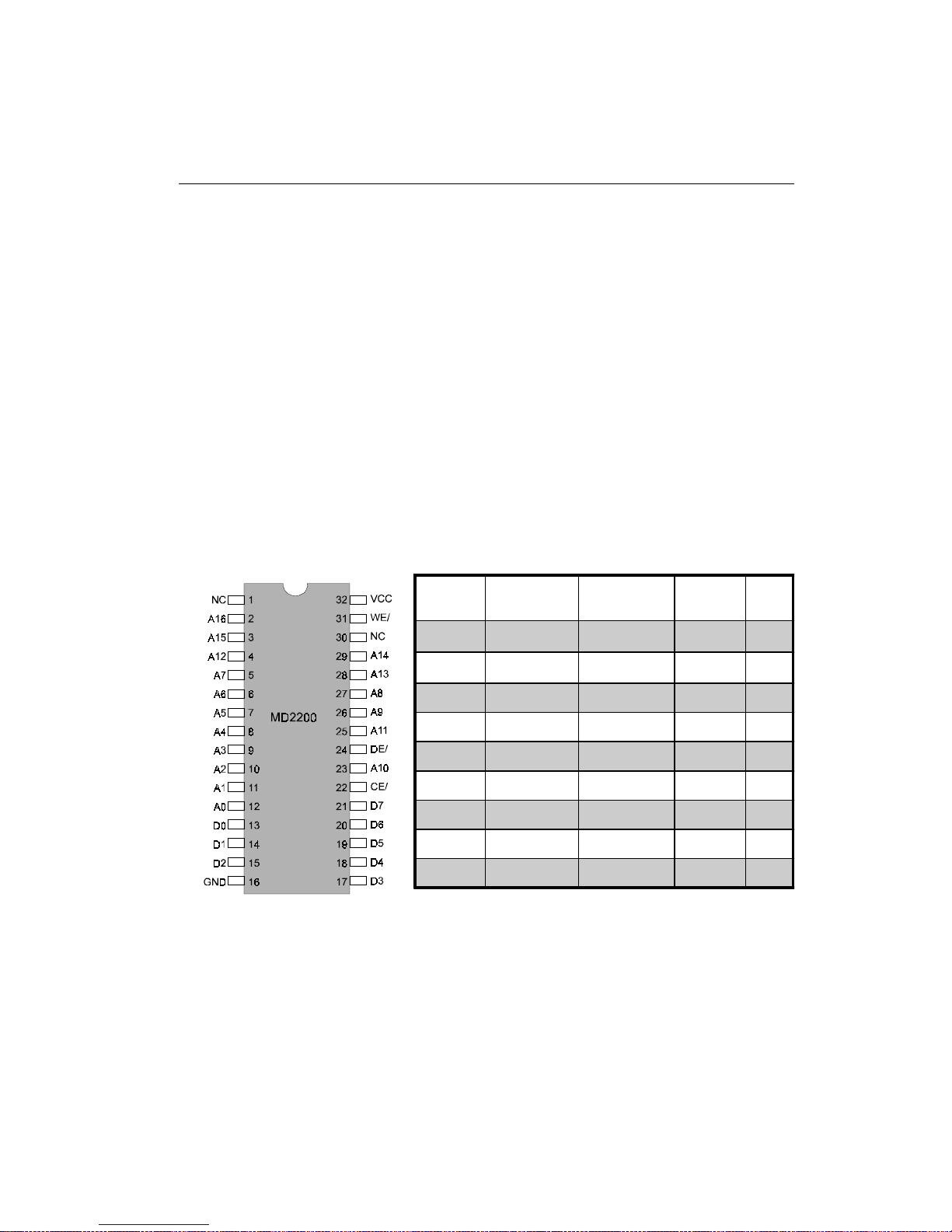
The DiskOnChip 2000 family of products provides a single chip solidstate flash disk in a standard 32-pin DIP package. The DiskOnChip
2000 is a solid-state disk with no moving parts, resulting in a significant reduction in power consumption and an increase in reliability.
The DiskOnChip is a small plug and play Flash disk. It is easy to use
and saves integration overhead.
The DiskOnChip 2000 family of products is available in capacities
ranging from 2MB to 288MB, unformatted. In order to manage the
disk, the DiskOnChip 2000 includes the TrueFFS, M-Systems Flash
File System proprietary software. The DiskOnChip 2000 package is
pin-to-pin compatible with a standard 32-pin EPROM device.
Note 1: Pins A13 through A16 are not used by the
MD2200. They are kept for socket backward compatibility with ED 1100 (DiskOnChip 1000)
Note 2: Pins 1 and 30 are not used by MD2200
OE /
Page 53

Chapter 2 Installation 41
DiskOnChip (DOC) 2000 Installation
When the DOC is installed correctly , a DOC will work like an HDD or
an FDD. T o install the DOC on the mainboard, follow the instructions
below:
1. Plug the DOC into the socket and make sure pin 1 of the DOC is
aligned with pin 1 of the socket.
2. Push the DOC into the socket until it is firmly seated in the socket.
Caution: the DOC may be permanently damage if it is installed
incorrectly .
3. Set the jumper for the memory address of the DOC.
Note:
The memory shadow function sometimes will create conflicts with
the memory window . Y ou should disable the memory shadow from
the BIOS SETUP if the DOC cannot be accessed.
Configure DOC as a Boot Device
To configure a DOC as a boot drive, you should copy the operating
system files onto the DOC. The following procedure is an example of
the initialization process.
1 . Install a DOC into your system.
2. Insert a bootable floppy disk in drive A: and boot the system.
3 . At the DOS prompt, type SYS C: to transfer the DOS system files
to the DOC (assuming the DiskOnChip is installed as drive C:).
Reboot the system.
4. Go to the BIOS Setup Utility by hitting the <DEL> key. Set the
type of Primary Master or C: Drive as Not Installed.
5. Remove the floppy disk from the drive A: and leave the BIOS
Setup Utility . The system should boot from the DOC.
Page 54

42 PCM-4896 User Manual
Page 55

Chapter 3 Award BIOS Setup 43
3
Award BIOS Setup
This chapter describes how to configure
the BIOS for the PCM-4896.
CHAPTER
Page 56

44 PCM-4896 User Manual
Starting Setup
The A ward BIOS is immediately activated when you first turn on the
computer. The BIOS reads system configuration information in CMOS
RAM and begins the process of checking out the system and configuring it through the power-on self test (POST).
When these preliminaries are finished, the BIOS seeks an operating
system on one of the data storage devices (hard drive, floppy drive,
etc.). The BIOS launches the operating system and hands control of
system operations to it.
During POST, you can start the Setup program in one of two ways:
1.By pressing Del immediately after switching the system on, or 2.By
pressing Del or pressing Ctrl-Alt-Esc when the following message
appears briefly at the bottom of the screen during POST :
TO ENTER SETUP BEFORE BOOT PRESS DEL KEY
If the message disappears before you respond and you still wish to
enter Setup, restart the system to try again by turning it OFF then ON
or pressing the RESET button on the system case. You may also
restart by simultaneously pressing Ctr-Alt-Del. If you do not press
the keys at the correct time and the system does not boot, an error
message appears and you are again asked to
PRESS F1 TO CONTINUE, DEL TO ENTER SETUP
Page 57

Chapter 3 Award BIOS Setup 45
Setup Keys
These keys help you navigate in Setup:
Up arrow Move to previous item
Down arrow Move to next item
Left arrow Move to the item in the left hand
Right arrow Move to the item in the right hand
Es c Main Menu: Quit and not save changes into
CMOS RAM
Other pages: Exit current page and return to
Main Menu
PgDn/+ Increase the numeric value or make
changes
PgDn/- Decrease the numeric value or make
changes
F1 General help, only for Status Page Setup
Menu and Option Page Setup Menu
F2 Change color from total 16 colors. F2 to
select color forward, Shift-F2 to select color
backward
F3 Calendar, only for Status Page Setup Menu
F4 Reserved
F5 Restore the previous CMOS value from
CMOS, only for Option Page Setup Menu
F6 Load the default CMOS RAM value from
BIOS default table, only for Option Page
Setup Menu
F7 Load the default
F8 Reserved
F9 Reserved
F10 Save all the CMOS changes, only for Main
Menu
Page 58

46 PCM-4896 User Manual
Getting Help
Press F1 to pop up a small help window that describes the appropriate keys to use and the possible selections for the highlighted item.
T o exit the Help W indow press Esc or the F1 key again.
In Case of Problems
If, after making and saving system changes with Setup, you discover
that your computer no longer is able to boot, the AwardBIOS sup-
ports an override to the CMOS settings that resets your system to its
default configuration.
You can invoke this override by immediately pressing Insert; when
you restart your computer. You can restart by either using the ON/
OFF switch, the RESET button or by pressing Ctrl-Alt-Delete.
The best advice is to alter only settings that you thoroughly understand. In particular, do not change settings in the Chipset screen
without a good reason. The Chipset defaults have been carefully
chosen by A ward Software or your system manufacturer for the best
performance and reliability. Even a seemingly small change to the
Chipset setup may causing the system to become unstable.
Page 59
Chapter 3 Award BIOS Setup 47
Main Setup Menu
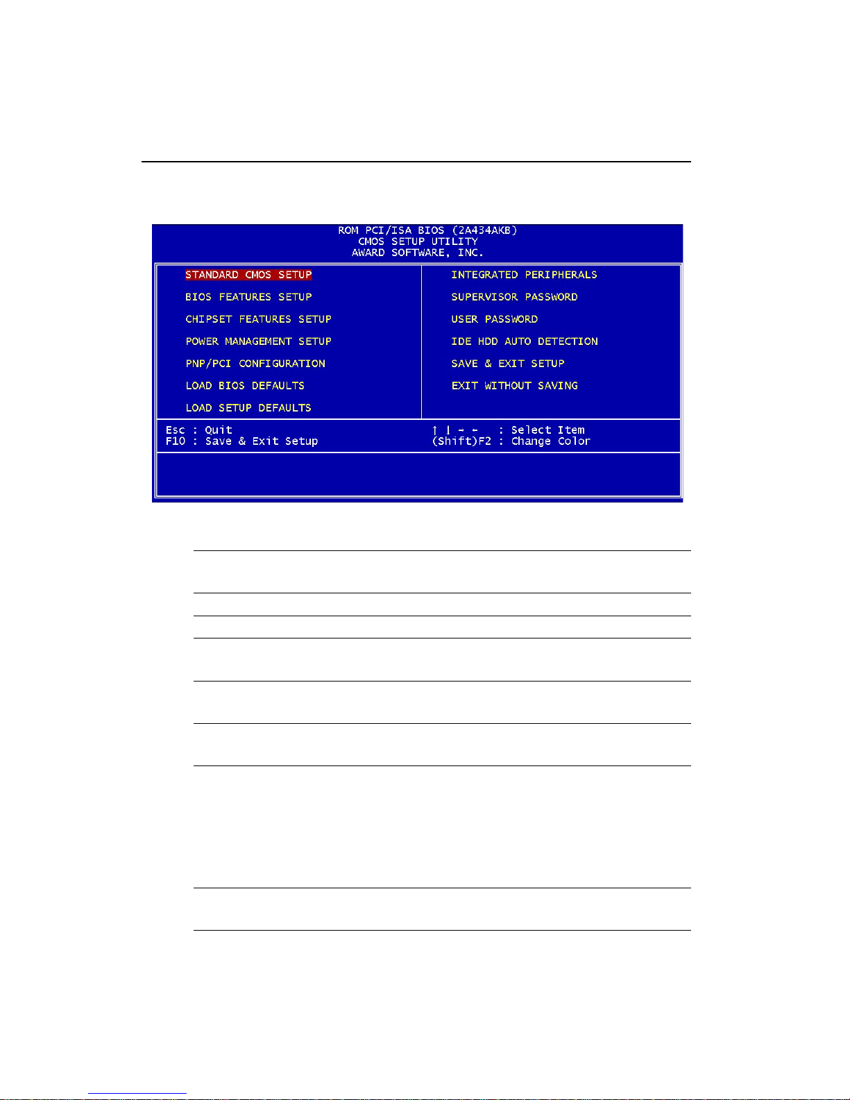
Standard CMOS Options in the original PC AT-compatible
BIOS.
BIOS Features Award Software enhanced BIOS options.
Chipset Features Options specific to your system chipset.
Power Advanced Power Management (APM)
Management options.
PnP/PCI Plug and Play standard and PCI Local Bus
Configuration configuration options.
Integrated I/O subsystems that depend on the inte-
Peripherals grated peripherals controller in your system.
Supervisor/User Change, set, or disable a password. In
Password Setting BIOS versions that allow separate user and
supervisor passwords, only the supervisor
password permits access to Setup. The
user password generally allows only
power-on access.
IDE HDD Auto Automatically detect and configure IDE hard
Detection disk parameters.
Page 60

48 PCM-4896 User Manual
Load BIOS BIOS defaults are factory settings for the
Defaults most stable, minimal-performance system
operations.
Load Setup Setup defaults are factory settings for
Defaults optimal-performance system operations.
Save & Exit Save settings in nonvolatile CMOS
Setup RAM and exit Setup.
Exit Without Abandon all changes and exit Setup.
Save
Page 61
Chapter 3 Award BIOS Setup 49
Standard CMOS Setup
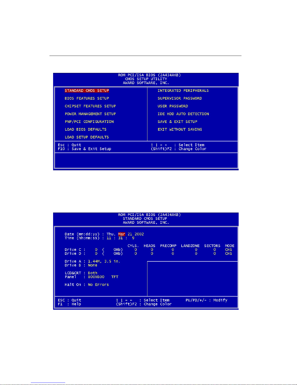
When you choose the ST ANDARD CMOS SETUP option from the
INITIAL SETUP SCREEN menu, the screen below is displayed.
Page 62

50 PCM-4896 User Manual
This standard setup menu allows users to configure system components such as the date, time, hard disk drive, floppy drive, display,
and memory . Online help for each field can be accessed by pressing
F1.
Date and Time Configuration
The BIOS determines the day of the week from the other date information. This field is for information only .
Press the left or right arrow key to move to the desired field (date,
month, year). Press the PgUp/- or PgDn/+ key to increment the setting, or type the desired value into the field.
The time format is based on the 24-hour military-time clock. For example, 1 p.m. is 13:00:00. Press the left or right arrow key to move to the
desired field. Press the PgUp/- or PgDn/+ key to increment the setting, or type the desired value into the field.
HARD DISKS
The BIOS supports up to four IDE drives. This section does not
show information about other IDE devices, such as a CD-ROM drive,
or about other hard drive types, such as SCSI drives.
NOTE: We recommend that you select type AUTO for all drives.
The BIOS can automatically detect the specifications and optimal
operating mode of almost all IDE hard drives. When you select type
AUTO for a hard drive, the BIOS detects its specifications during
POST , every time the system boots.
If you do not want to select drive type AUTO, other methods of
Page 63

Chapter 3 Award BIOS Setup 51
selecting the drive type are available:
1.Match the specifications of your installed IDE hard drive(s) with
the preprogrammed values for drive types 1 through 45.
2.Select USER and enter values into each drive parameter field.
3.Use the IDE HDD AUTO DECTECTION function in Setup.
Here is a brief explanation of drive specifications:
•Type: The BIOS contains a table of pre-defined drive types. Each
defined drive type has a specified number of cylinders,
number of heads, write precompensation factor, landing
zone, and number of sectors. Drives whose specifications
do not accommodate any pre-defined type are classified as
type USER.
•Size: Disk drive capacity (approximate). Note that this size is
usually slightly greater than the size of a formatted disk
given by a disk-checking program.
• Cyls: Number of cylinders
• Head: Number of heads
• Precomp: Write precompensation cylinder
• Landz: Landing zone
• Sector: Number of sectors
• Mode: Auto, Normal, Large, or LBA
- Auto: The BIOS automatically determines the optimal mode.
- Normal: Maximum number of cylinders, heads, and sectors
supported are 1024, 16, and 63.
- Large: For drives that do not support LBA and have more than
1024 cylinders.
Page 64

52 PCM-4896 User Manual
- LBA (Logical Block Addressing): During drive accesses, the
IDE controller transforms the data address described by
sector, head, and cylinder number into a physical block
address, significantly improving data transfer rates. For
drives with greater than 1024 cylinders.
Drive A
Drive B
Select the correct specifications for the diskette drive(s) installed in
the computer .
None No diskette drive installed
360K, 5.25 in 5-1/4 inch PC-type standard drive; 360
kilobyte capacity
1.2M, 5.25 in 5-1/4 inch AT-type high-density drive; 1.2
megabyte capacity
720K, 3.5 in 3-1/2 inch double-sided drive; 720 kilobyte
capacity
1.44M, 3.5 in 3-1/2 inch double-sided drive; 1.44 mega
byte capacity
2.88M, 3.5 in 3-1/2 inch double-sided drive; 2.88 mega
byte capacity
LCD & CRT
This field may appear as an alternative to the V ideo field. select your
video display device:
LCD Liquid crystal display
CRT Auxiliary monitor
Both Display on both devices
Page 65
Chapter 3 Award BIOS Setup 53
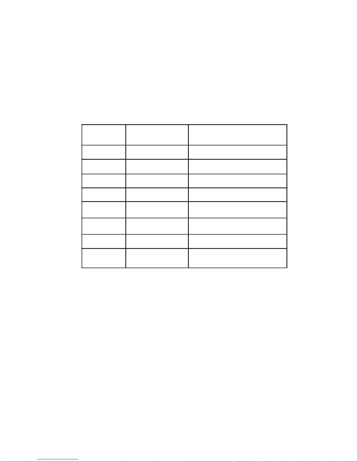
Pannel:
This selection item allows user to select LCD BIOS to match the LCD
types. There are eight, LCD types available for users to select as their
LCD display modes as below:
emandnarBemanledoMtamroF
prahS08X51XLNTSD867x4201
prahSP38146MLONOM084x046
prahSP53C46MLNTSD084x046
prahS04S21MLNTSD006x008
CEN01-33CA8446LN)stib21(TFT084x046
abihsoTA902C01MTLTFT)stib81(084x046
CEN40-62CA0608LNTFT006x008
prahS30x41QL)stib63(TFT867x4201
Page 66

54 PCM-4896 User Manual
Halt On
During the power-on-self-test (POST), the computer stops if the BIOS
detects a hardware error . Y ou can tell the BIOS to ignore certain errors
during POST and continue the boot-up process. These are the selections:
• No errors: POST does not stop for any errors.
• All errors: If the BIOS detects any non-fatal error, POST stops
and prompts you to take corrective action.
• All, But Keyboard: POST does not stop for a keyboard error , but
stops for all other errors
• All, But Diskette: POST does not stop for diskette drive errors,
but stops for all other errors.
• All, But Disk/Key: POST does not stop for a keyboard or disk
error, but stops for all other errors.
Memory
You cannot change any values in the Memory fields; they are only
for your information. The fields show the total installed random access memory (RAM) and amounts allocated to base memory , extended memory, and other (high) memory. RAM is counted in kilobytes
(KB: approximately one thousand bytes) and megabytes (MB: approximately one million bytes).
RAM is the computer's working memory , where the computer stores
programs and data currently being used, so they are accessible to the
CPU. Modern personal computers may contain up to 64 MB, 128 MB,
or more.
•Base Memory
T ypically 640 KB. Also called conventional memory . The DOS operating system and conventional applications use this area.
Page 67

Chapter 3 Award BIOS Setup 55
•Extended Memory
Above the 1-MB boundary . Early IBM personal computers could not
use memory above 1 MB, but current PCs and their software can use
extended memory .
•Other Memory
Between 640 KB and 1 MB; often called High memory . DOS may load
terminate-and-stay-resident (TSR) programs, such as device drivers,
in this area, to free as much conventional memory as possible for
applications. Lines in your CONFIG.SYS file that start with LOADHIGH load programs into high memory .
Page 68
56 PCM-4896 User Manual
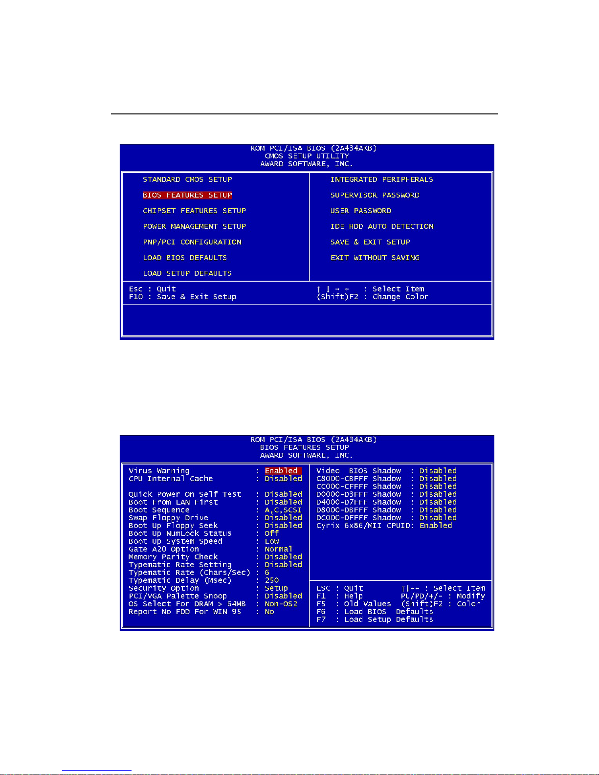
BIOS Features Setup
By choosing the BIOS FEA TURES SETUP option from the INITIAL
SETUP SCREEN menu, the screen below is displayed.
Page 69

Chapter 3 Award BIOS Setup 57
The displayed configuration is based on the manufacturer's SETUP
DEF AUL TS settings.
Virus Warning
When enabled, you receive a warning message if a program (specifically , a virus) attempts to write to the boot sector or the partition table
of the hard disk drive. You should then run an anti-virus program.
Keep in mind that this feature protects only the boot sector, not the
entire hard drive.
NOTE: Many disk diagnostic programs that access the boot sector
table can trigger the virus warning message. If you plan to run such
a program, we recommend that you first disable the virus warning.
CPU Internal Cache/External Cache
Cache memory is additional memory that is much faster than conventional DRAM (system memory). CPUs from 486-type on up contain
internal cache memory , and most, but not all, modern PCs have additional (external) cache memory. When the CPU requests data, the
system transfers the requested data from the main DRAM into cache
memory , for even faster access by the CPU.
The External Cache field may not appear if your system does not have
external cache memory .
Quick Power On Self T est
Select Enabled to reduce the amount of time required to run the power-on-self-test (POST). A quick POST skips certain steps. W e recommend that you normally disable quick POST . Better to find a problem
during POST than lose data during your work.
Boot From LAN First
T o enable this function for booting from LAN (Optinal function).
Page 70

58 PCM-4896 User Manual
Boot Sequence
The original IBM PCs loaded the DOS operating system from drive A
(floppy disk), so IBM PC-compatible systems are designed to search
for an operating system first on drive A, and then on drive C (hard
disk). However, the BIOS now of fers many boot sequence options.
Swap Floppy Drive
This field is effective only in systems with two floppy drives. Selecting enabled assigns physical drive B to logical drive A, and physical
drive A to logical drive B.
Boot Up Floppy Seek
When Enabled, the BIOS tests (seeks) floppy drives to determine
whether they have 40 or 80 tracks. Only 360-KB floppy drives have 40
tracks; drives with 720 KB, 1.2 MB, and 1.44 MB capacity all have 80
tracks. Because very few modern PCs have 40-track floppy drives, we
recommend that you set this field to Disabled to save time.
Boot Up NumLock Status
Toggle between On or Off to control the state of the NumLock key
when the system boots. When toggled On, the numeric keypad generates numbers instead of controlling cursor operations.
Boot Up System Speed
To speed the system boot up, the default setting is Enable.
Gate A20 Option
Gate A20 refers to the way the system addresses memory above 1
MB (extended memory). When set to Fast, the system chipset controls Gate A20. When set to Normal, a pin in the keyboard controller
controls Gate A20. Setting Gate A20 to Fast improves system speed,
particularly with OS/2 and Windows.
T ypematic Rate Setting
Key strokes repeat at a rate determined by the keyboard controller.
When enabled, the typematic rate and typematic delay can be selected.
Page 71

Chapter 3 Award BIOS Setup 59
T ypematic Rate (Chars/Sec)
Sets the number of times a second to repeat a key stroke when you
hold the key down.
T ypematic Delay (Msec)
Sets the delay time after the key is held down before it being to repeat
the key stroke.
T ypematic Delay (Msec)
Sets the delay time after the key is held down before it being to repeat
the key stroke.
Security Option
If you have set a password, select whether the password is required
every time the System boots, or only when you enter Setup.
PCI/VGA Palette Snoop
To monitor the VGA palette and correct the color display problem
caused by some MPEG card.
OS Select For DRAM>64MB
Select the operating system that is running with greater than 64MB or
RAM on the system.
No Report of FDD in Windows 95
Set this option to <NO> when using Windows 98 version, or the
FDD will not work.
Shadow
Software that resides in a read-only memory (ROM) chip on a device
is called firmware. The A wardBIOS permits shadowing of firmware
such as the system BIOS, video BIOS, and similar operating instructions that come with some expansion peripherals, such as, for example, a SCSI adaptor .
Shadowing copies firmware from ROM into system RAM, where the
CPU can read it through the 16-bit or 32-bit DRAM bus. Firmware not
shadowed must be read by the system through the 8-bit X-bus. Shad
Page 72

60 PCM-4896 User Manual
owing improves the performance of the system BIOS and similar ROM
firmware for expansion peripherals, but it also reduces the amount of
high memory (640 KB to 1 MB) available for loading device drivers,
etc.
Enable shadowing into each section of memory separately. Many
system designers hardwire shadowing of the system BIOS and eliminate a System BIOS Shadow option.
V ideo BIOS shadows into memory area C0000-C7FFF . The remaining
areas shown on the BIOS Features Setup screen may be occupied by
other expansion card firmware. If an expansion peripheral in your
system contains ROM-based firmware, you need to know the address range the ROM occupies to shadow it into the correct area of
RAM.
Cyrix 6x86/MII CPUID:
Enable this item to support Cyrix 6x86/MII series CPUID.
Page 73
Chapter 3 Award BIOS Setup 61
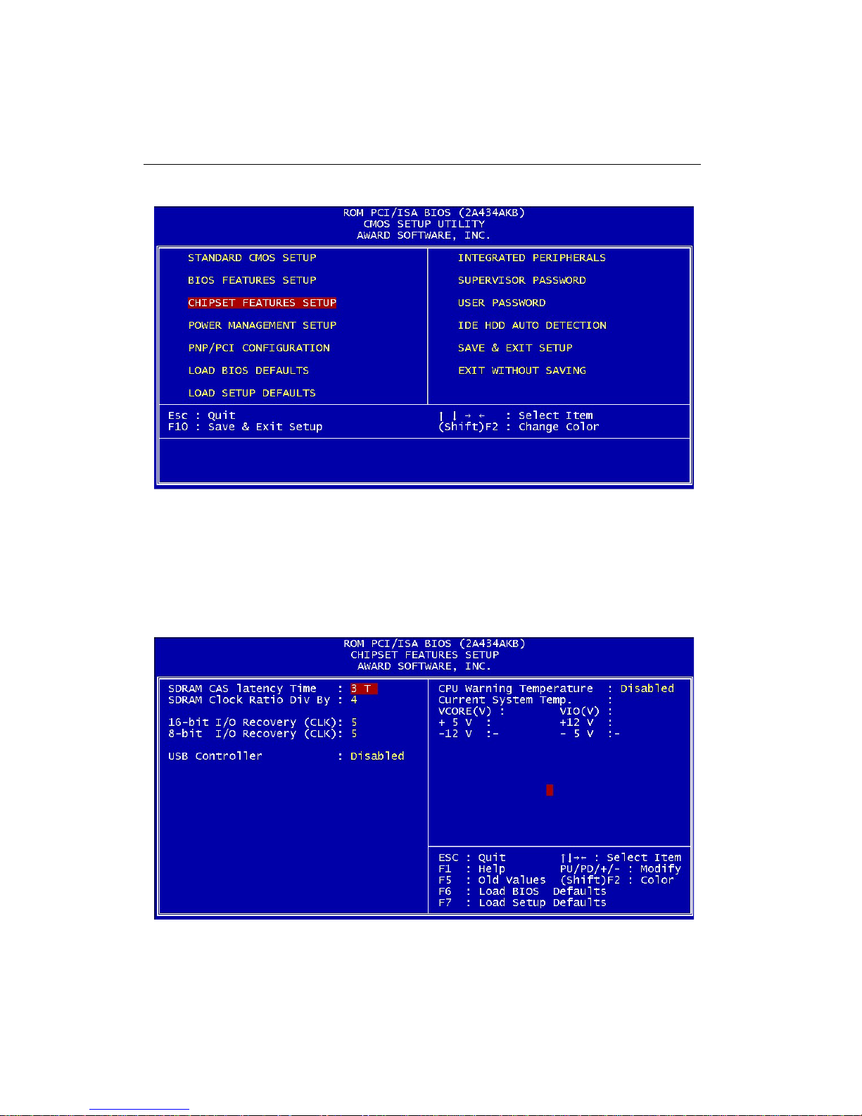
CHIPSET Features Setup
By choosing the CHIPSET FEA TURES SETUP option from the
INITIAL SETUP SCREEN menu, the screen below is displayed.
Page 74

62 PCM-4896 User Manual
The displayed configuration is based on the manufacturer's SETUP
DEF AUL TS settings.
This section allows you to configure the system based on the specific features of the installed chipset. This chipset manages bus speeds
and access to system memory resources, such as SDRAM. It also
coordinates communications between the conventional ISA bus and
the PCI bus. It must be stated that these items should never need to
be altered. The default settings have been chosen because they
provide the best operating conditions for your system. The only time
you might consider making any changes would be if you discovered
that data was being lost while using your system.
Because of the complexity and technical nature of some of the
options, not all of the options are described here.
SDRAM CAS Latency Time
When synchronous DRAM is installed, you can control the
number of CLKs between when the SDRAMs sample a read
command and when the contoller samples read data from the
SDRAMs. Do not reset this field from the default value specified
by the system designer.
8/16 Bit I/O Recovery Time
The I/O recovery mechanism adds bus clock cycles between PCIoriginated I/O cycles to the ISA bus. This delay takes place
because the PCI bus is so much faster than the ISA bus.
These two fields let you add recovery time (in bus clock cycles) for
16-bit and 8-bit I/O.
USB Controller
Select Enabled if your system contains a Universal Serial Bus
(USB) controller and you have USB peripherals
CPU Warning Temperature
If the CPU temperature extends beyond high or low limit, any
warning mechanism programmed into your system will be activated.
Page 75
Chapter 3 Award BIOS Setup 63
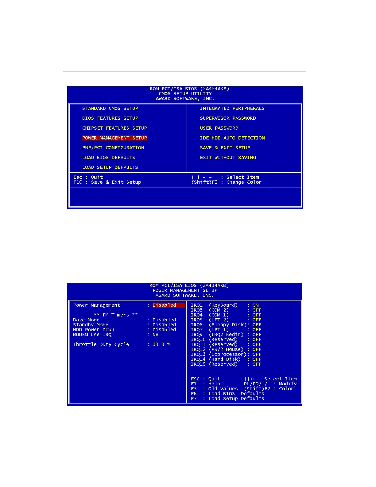
Power Management Setup
By choosing the POWER MANAGEMENT option from the
INITIAL SETUP SCREEN menu, the screen below is displayed.
Page 76

64 PCM-4896 User Manual
Power Management
This option allows you to select the type (or degree) of power saving
for Doze, Standby, and Suspend modes.
This table describes each power management mode:
Max Saving Maximum power savings. Only Available for
SL CPUs. Inactivity period is 1 minute in
each mode.
User Define Set each mode individually. Select time-out
periods in the section for each mode,
below.
Min Saving Minimum power savings. Inactivity period is
1 hour in each mode.
Page 77

Chapter 3 Award BIOS Setup 65
Doze Mode
After the selected period of system inactivity , the CPU clock throttles
to a small percentage of its duty cycle between 10 percent and 25
percent for most chipsets. All other devices still operate at full speed.
Standby Mode
After the selected period of system inactivity , the fixed disk drive and
the video shut off while all other devices still operate at full speed.
HDD Power Down
After the selected period of drive inactivity , any system IDE devices
compatible with the A T A-2 specification or later power manage themselves, putting themselves into an idle state after the specified timeout and then waking themselves up when accessed.
MODEM Use IRQ
Name the interrupt request (IRQ) line assigned to the modem (if any)
on your system. Activity of the selected IRQ always awakens the
system.
Throttle Duty Cycle
When the system enters Doze mode, the CPU clock runs only part of
the time. You may select the percent of time that the clock runs.
Page 78
66 PCM-4896 User Manual
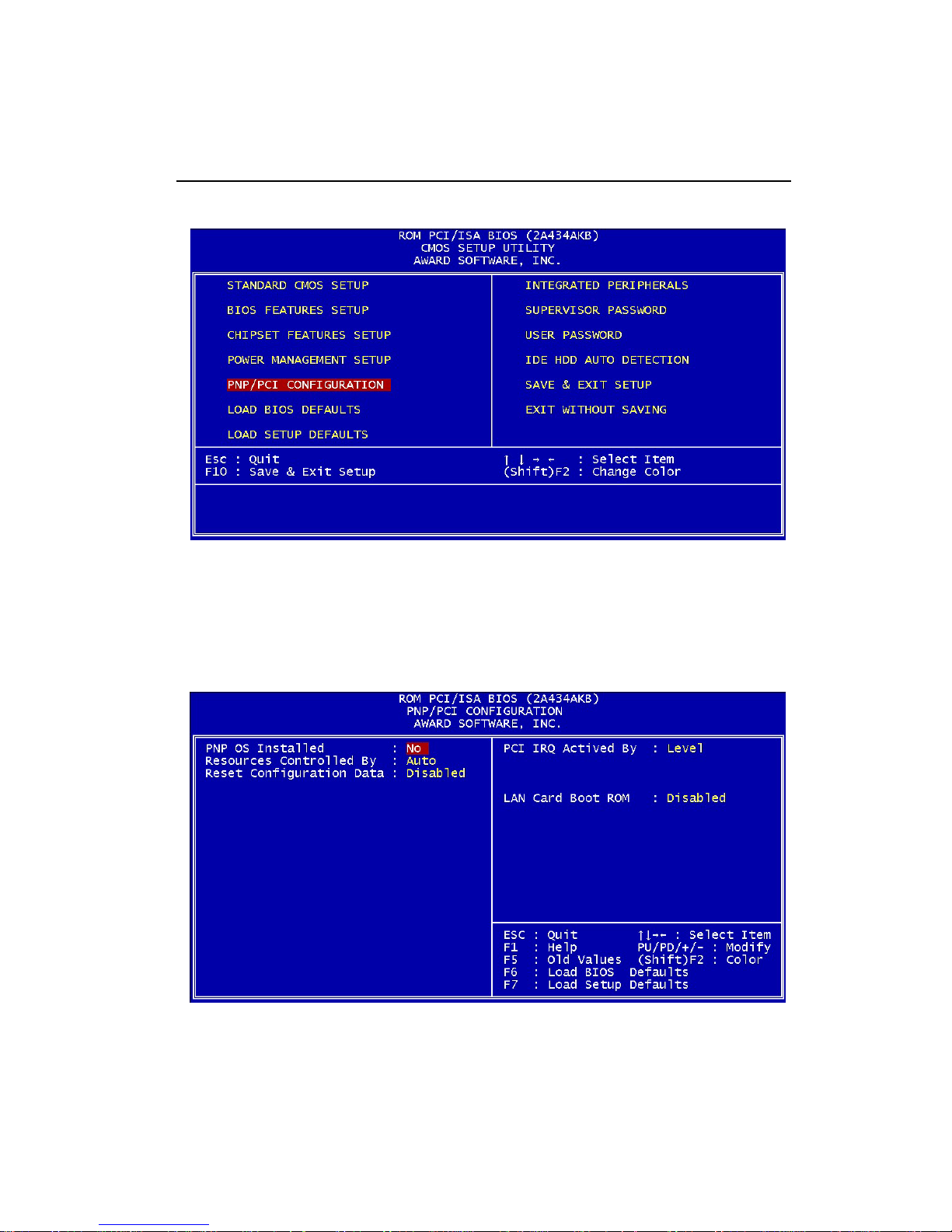
PNP/PCI Configuration Setup
By choosing the PNP/PCI CONFIGURA TION SETUP option from the
initial SETUP SCREEN menu, the screen below is displayed.
Page 79

Chapter 3 Award BIOS Setup 67
PNP OS Installed
Select Y es if the system operating environment is Plug-and-Play aware
(e.g., Windows 95).
Resources Controlled By
The Plug and Play AwardBIOS can automatically configure all the
boot and Plug and Play-compatible devices. If you select Auto, all
the interrupt request (IRQ) and DMA assignment fields disappear, as
the BIOS automatically assigns them.
T o enable IDE DMA mode, please choose "Manual" and set IRQ-15
to be Legacy ISA.
Reset Configuration Data
Normally , you leave this field Disabled. Select Enabled to reset Extended System Configuration Data (ESCD) when you exit Setup if
you have installed a new add-on and the system reconfiguration has
caused such a serious conflict that the operating system cannot boot.
PCI IRQ Activated by
Leave the IRQ trigger set at Level unless the PCI device assigned to
the interrupt specifies Edge-triggered interrupts.
LAN Card Boot ROM
T o enable the LAN boot ROM when it is installed.
Page 80
68 PCM-4896 User Manual
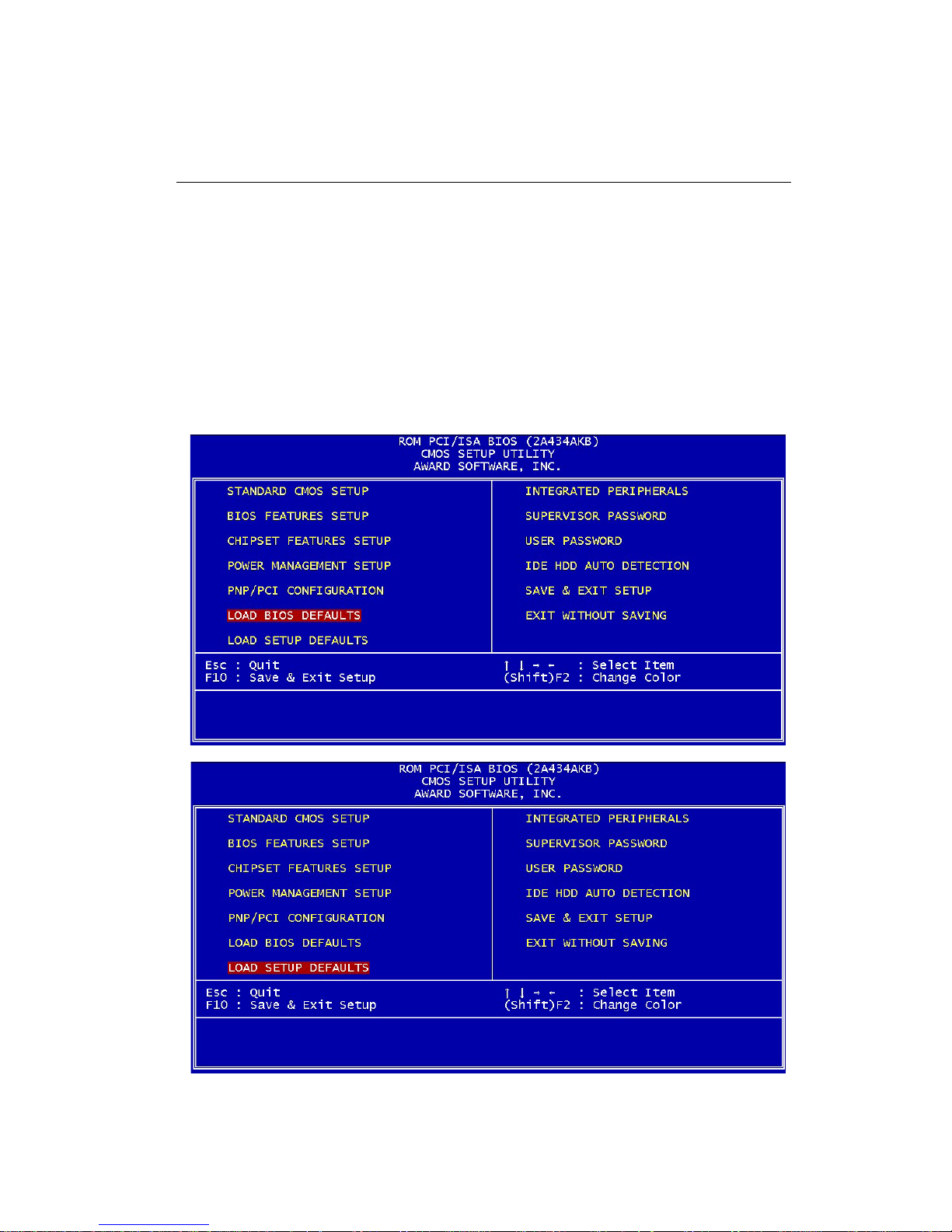
Load BIOS Defaults/Load Setup Defaults
LOAD BIOS DEFAULTS loads the default system values directly
from ROM. The BIOS DEF AUL TS provides the most stable settings,
though they do not provide optimal performance. LOAD SETUP
DEF AUL TS, on the other hand, provides for maximum system performance. If the stored record created by the setup utility becomes
corrupted (and therefore unusable), BIOS defaults will load automatically when you turn the PCM-4896 on.
Page 81
Chapter 3 Award BIOS Setup 69
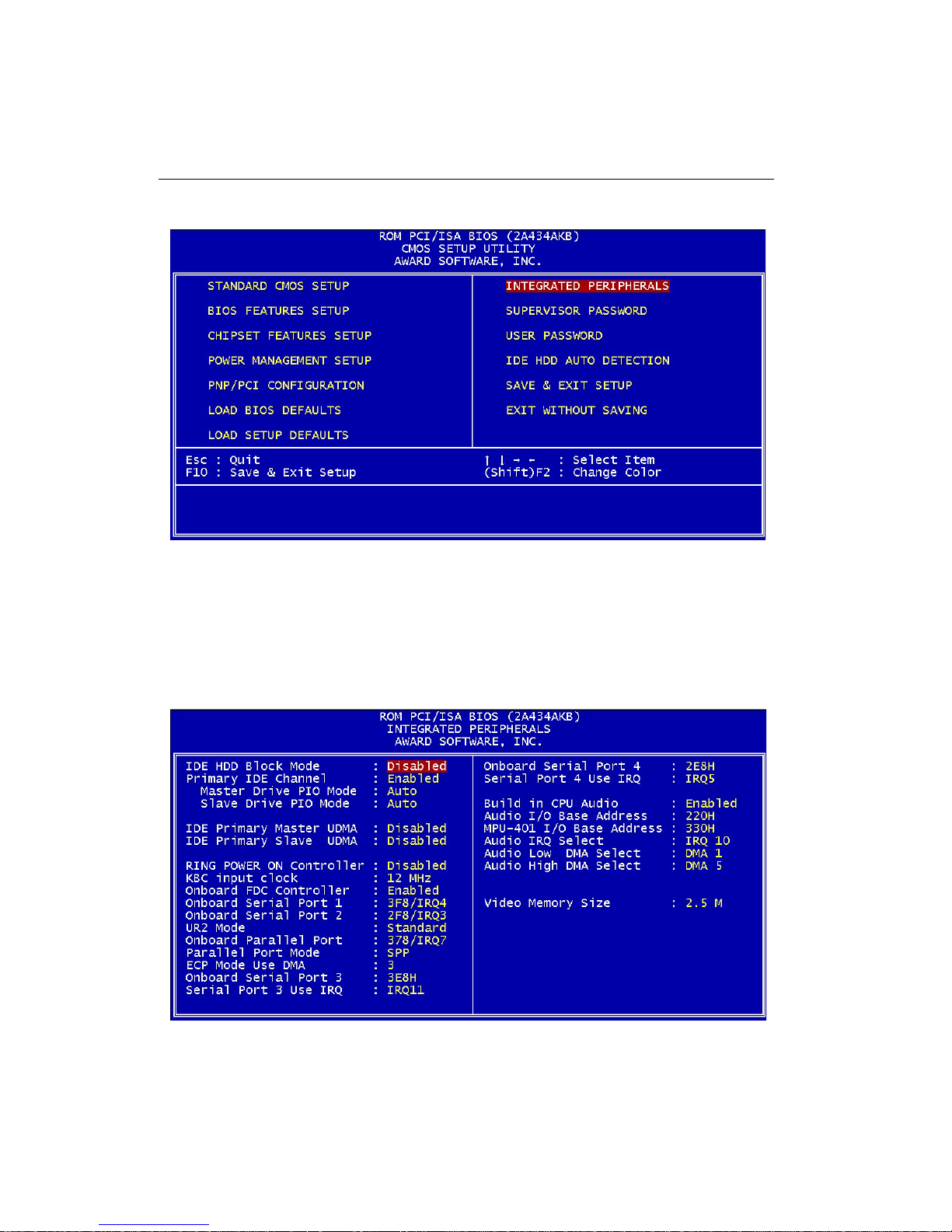
Integrated Peripherals Setup
By choosing the INTEGRA TD PERIPHERALS option from the initial
SETUP SCREEN menu, the screen below is displayed.
Page 82

70 PCM-4896 User Manual
IDE HDD Block Mode
Select Enabled only if your hard drives support block mode.
Primary IDE Channel
Select Enable to activate the primary IDE interface.
Master Drive PIO Mode/Slave Drive PIO Mode
T o enable the PIO mode from 0~4 for Master and Slave drives.
IDE Primary Master/Slave UDMA
UDMA (Ultra DMA) is a DMA data transfer protocol that utilizes
ATA commands and the AT A bus to allow DMA commands to transfer data at a maximum burst rate of 33 MB/s. When you select Auto in
the four IDE UDMA fields (for each of up to four IDE devices that the
internal PCI IDE interface supports), the system automatically determines the optimal data transfer rate for each IDE device.
KBC Input Clock
The system designer must select the correct frequency for the keyboard controller input clock. Do not change this value from the default value.
Onboard FDC Controller
Select Enabled if your system has a floppy disk controller (FDC)
installed on the system board and you wish to use it. If you install an
add-in FDC or the system has no floppy drive, select Disabled in this
field.
Onboard Serial Ports (1, 2)
Select a logical COM port name and matching address for the first
and second serial ports. Select an address and corresponding interrupt for the first and second serial ports.
UR2 Mode
Select an operating mode for the second serial port:
Page 83

Chapter 3 Award BIOS Setup 71
Onboard Parallel Port
Select a logical LPT port address and corresponding interrupt for
the physical parallel port
Parallel Port Mode
Select an operating mode for the onboard parallel (printer) port. Select Normal, Compatible, or SPP unless you are certain your hardware
and software both support one of the other available modes
ECP Mode Use DMA
Select a DMA channel for the port.
Onboard Serial Port 3.
Select a matching address for the third serial ports.
Serial Port 3 Use IRQ.
Select a corresponding interrupt for the third serial ports.
Onboard Serial Port 4.
Select a matching address for the fourth serial ports.
Serial Port 4 Use IRQ.
Select a corresponding interrupt for the fourth serial ports.
Bulid in CPU Audio
Enable or disable CPU bulit-in audio.
Video Memory Size
Specify the size of system memory to allocate for video memory
Page 84
72 PCM-4896 User Manual
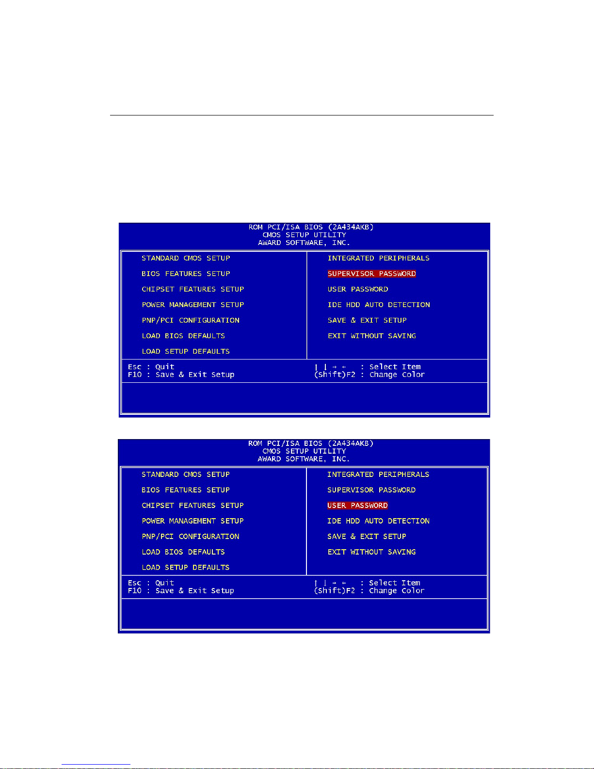
Supervisor/User Password Setting
You can set either SUPER VISOR or USER PASSWORD, or both of
them. The difference between the two is that the supervisor password allows unrestricted access to enter and change the options of
the setup menus, while the user password only allows entry to the
program, but not modify options.
Page 85

Chapter 3 Award BIOS Setup 73
When you select this function, a message appears at the center of
the screen:
ENTER PASSWORD:
T ype the password, up to eight characters, and press Enter. T yping a
password clears any previously entered password from CMOS memory .
Now the message changes:
CONFIRM PASSWORD:
Again, type the password and press Enter.
To abort the process at any time, press Esc.
In the Security Option item in the BIOS Features Setup screen, select
System or Setup:
System Enter a password each time the system boots and when
ever you enter Setup.
Setup Enter a password when ever you enter Setup.
NOTE: To clear the password, simply press Enter when asked to
enter a password. Then the password function is disabled.
Page 86
74 PCM-4896 User Manual
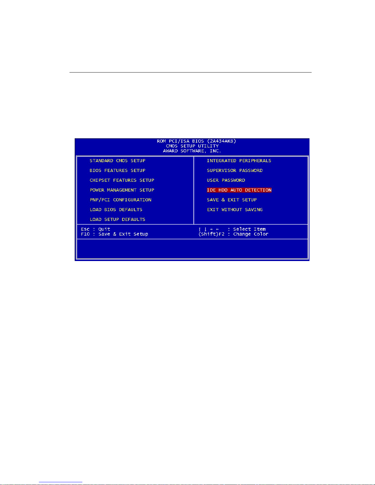
IDE HDD Auto Detection
The IDE HDD AUTO DETECTION utility can automatically detect
the IDE hard disk installed in your system. You can use it to selfdetect and/or correct the hard disk type configuration.But you need to
repeat the setup for each of the IDE combinations:
Page 87
Chapter 3 Award BIOS Setup 75
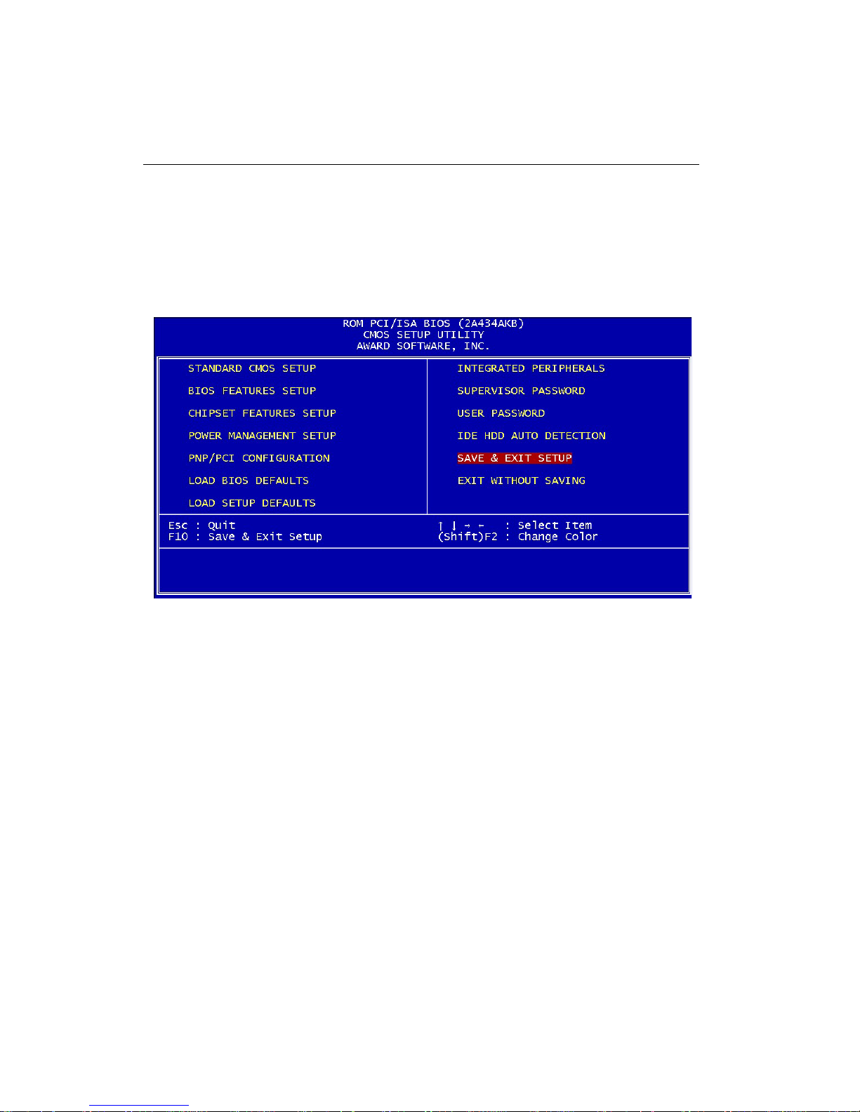
Save & Exit Setup
If you select this option and press <ENTER>, the values entered in
the setup utility will be recorded in the chipset's CMOS memory . The
microprocessor will check this every time you turn your system on
and compare this to what it finds as it checks the system. This record
is required for the system to operate.
Page 88
76 PCM-4896 User Manual
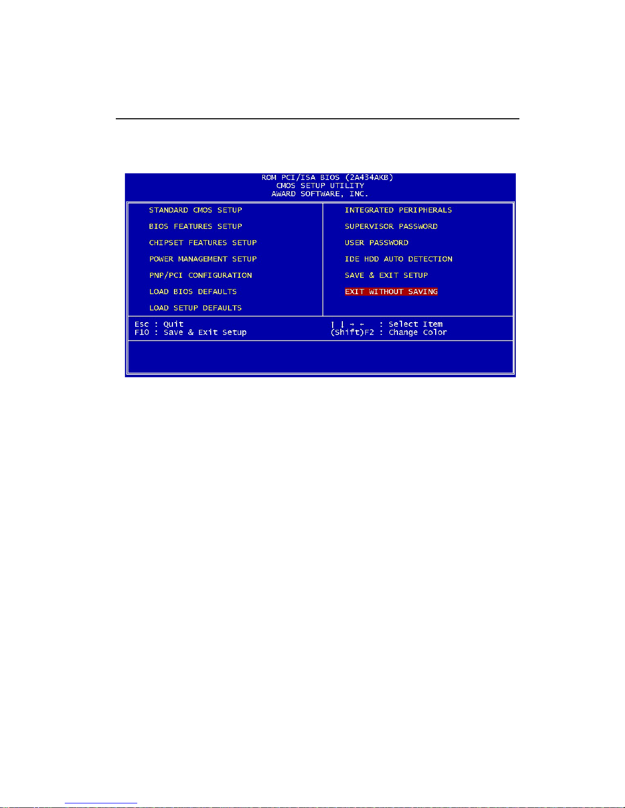
Exit Without Saving
If you select this option and press <ENTER>, the values entered in
the setup utility won't be recorded in the chipset's CMOS memory .
Page 89

Chapter 4 Driver Installation 77
4
Flat Panel/CRT
Controller Display
Drivers and Utilities
This chapter provides information about:
• Driver types and installation
CHAPTER
Page 90

78 PCM-4896 User Manual
Software Drivers
This chapter describes the operation and installation of the display drivers supplied on the Supporting CD-ROM that are shipped with your
product.
The onboard VGA adapter is based on the CHIPS VGA Flat Panel/CR T
controller and is fully IBM VGA compatible. This controller offers a large
set of extended functions and higher resolutions. If you intend to use
your VGA adapter in standard VGA modes only, you do not need to
install any of these drivers. Since your VGA adapter is fully compatible,
it does not require any special drivers to operate in standard modes.
The purpose of the enclosed software drivers is to take advantage of the
extended features of the CHIPS VGA Flat Panel/CR T controller.
Hardware Configuration
Some of the high-resolution drivers provided in this package will work
only in certain system configurations. If a driver does not display correctly , try the following:
1 . Change the display controller to CRT-only mode, rather than flat pan-
el or simultaneous display mode. Some high-resolution drivers will
display correctly only in CR T mode.
2 . If a high-resolution mode is not supported on your system, try using
a lower-resolution mode. For example, 1024 x 768 mode will not work
on some systems, but 800 x 600 mode is supported on most.
Page 91

Chapter 4 Driver Installation 79
Necessary to Know
The instructions in this manual assume that you understand elementary
concepts of MS-DOS and the IBM Personal Computer. Before you attempt to install any driver from the Supporting CD-ROM, you should:
• Know how to copy files from a CD-ROM to a directory on the hard disk
• Understand the MS-DOS directory structure
If you are uncertain about any of these concepts, please refer to the DOS
or OS/2 user reference guides for more information before you proceed
with the installation.
Before You Begin
Make sure you know the version of the application for which you are
installing drivers. The Supporting CD-ROM contain drivers for several
versions of certain applications. For your driver to operate properly , you
must install the driver for your version of the application program.
Page 92
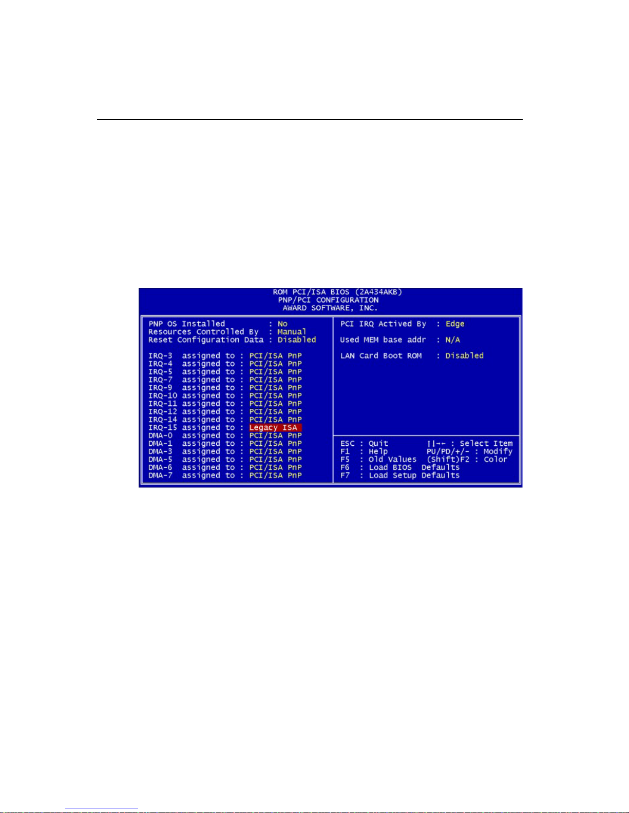
80 PCM-4896 User Manual
Windows® 95/98
These drivers are designed to work with Microsoft Windows. You
just install these drivers through the Windows operating system.
Before you start to install the driver , please make sur e you have right
setting for IRQ-15 in "PnP/PCI Configuration"
IRQ-15 assigned to : Legacy ISA
Then run "Cyrix MediaGX Certified Win9X Drivers 4.0.exe" before
you install VGA driver .
cd-rom:\Driver\Cyrix MediaGX Certified Win9x Drivers 4.0
"cd-rom" : the drive letter of your CD-ROM drive0.exe
Page 93
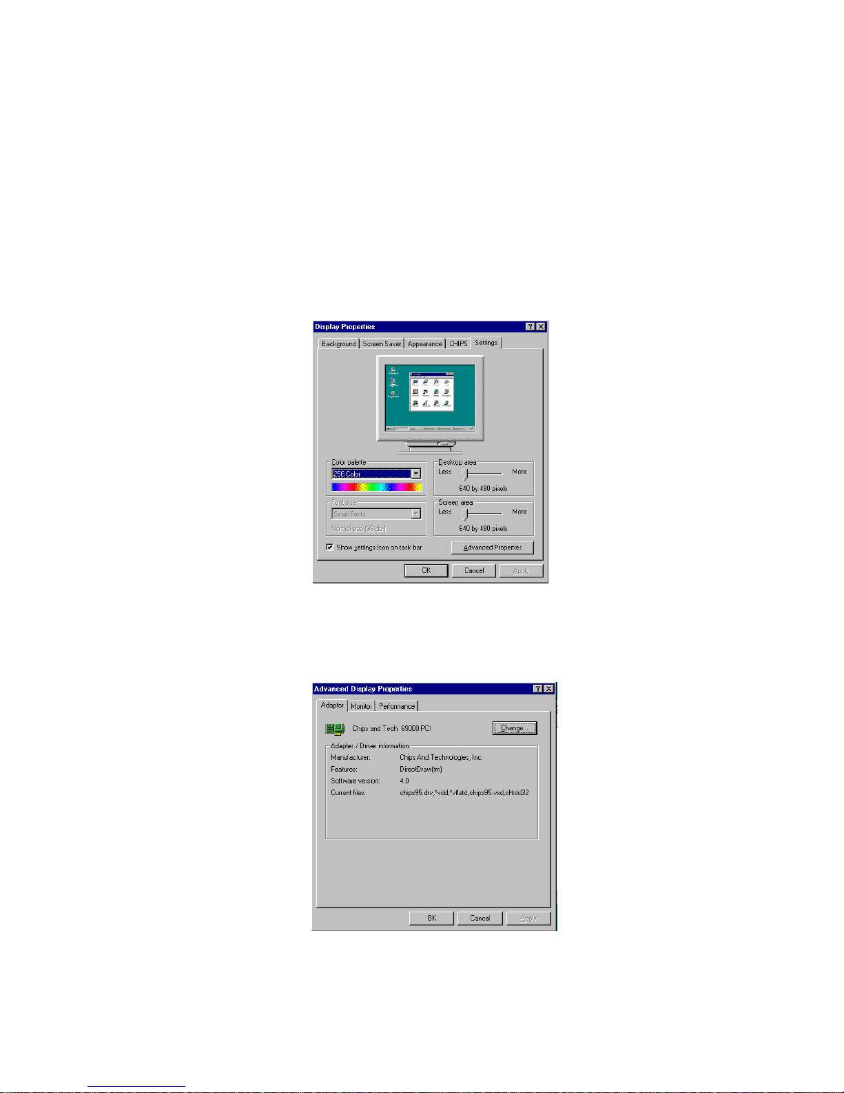
Chapter 4 Driver Installation 81
Driver Installation
1. Install Windows 95 as you normally would for a VGA display.
Click the Start button, go to Settings and click on Control Panel.
Choose the Display icon and double click on the icon. In the
Display Properties window , show as figure 1:
Click the setting buttom, then click the Advanced Properties icon
into the Advanced Display properties windows, show as figure2:
figure 1
figure 2
Page 94
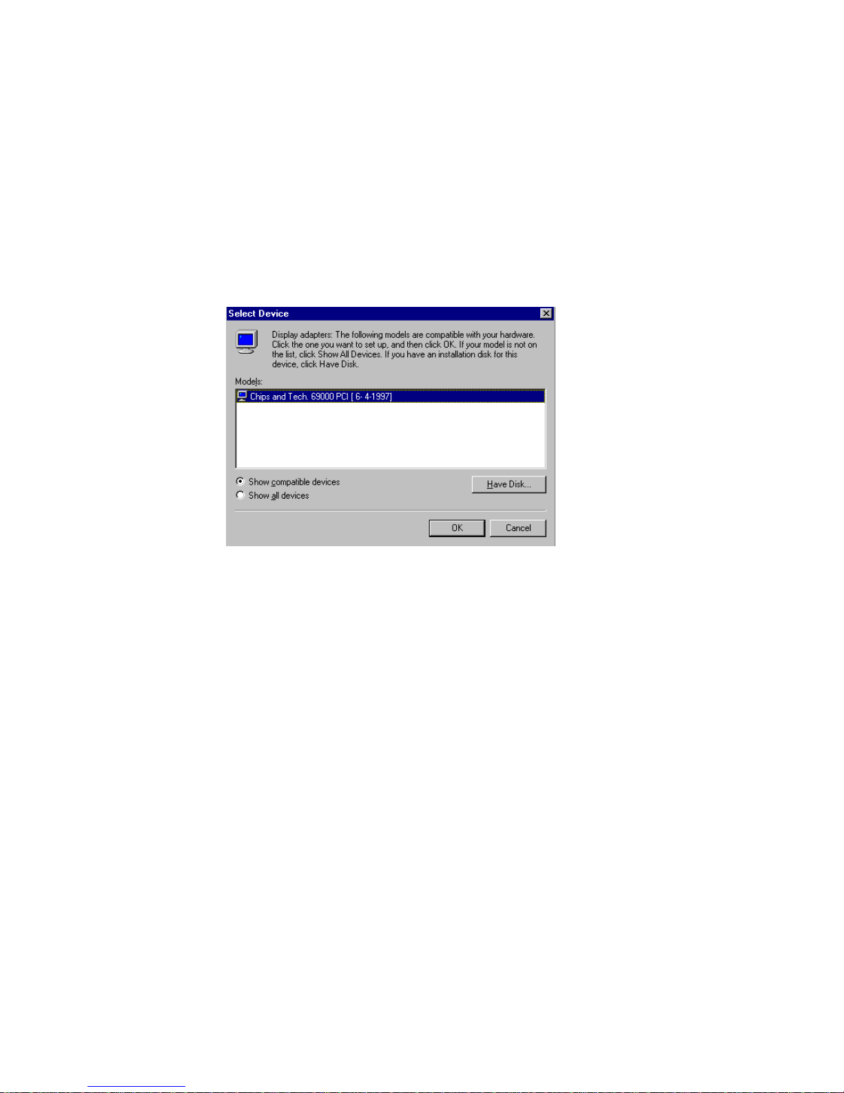
82 PCM-4896 User Manual
click on Change Display T ype. In the Change Display Type window ,
click on the Change button under Adapter Type into the select Device window show as figure 3: This will bring up the Select Device
window .
figure 3
Page 95
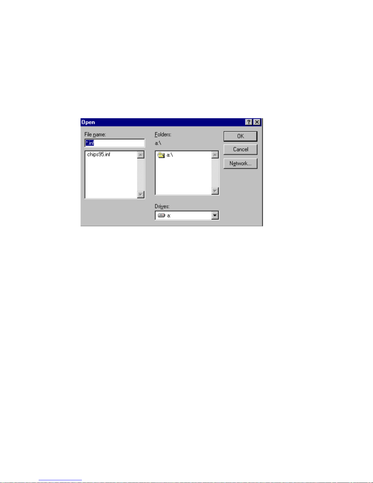
Chapter 4 Driver Installation 83
2 . Place the Supporting CD-ROM in your CD-ROM drive.
In the Select Device window , click on Have Disk, Select Browse, and
find the Win95(W in98) driver "chips95.inf"("chips98.inf) in the Sup-
porting CD-ROM:
Win95:
cd-rom: \Driver\vga driver\Win95\chips95.inf and then click OK.
Win98:
cd-rom: \Driver\vga driver\Win98\chips98.inf and then click OK.
"cd-rom" : the drive letter of your CD-ROM drive
The name of the Chips And T ech "69000 PCI " driver will appear
highlighted in the Models list boxfhow as figure. Click OK to start
the driver installation show as figure 5:
figure 4
Page 96
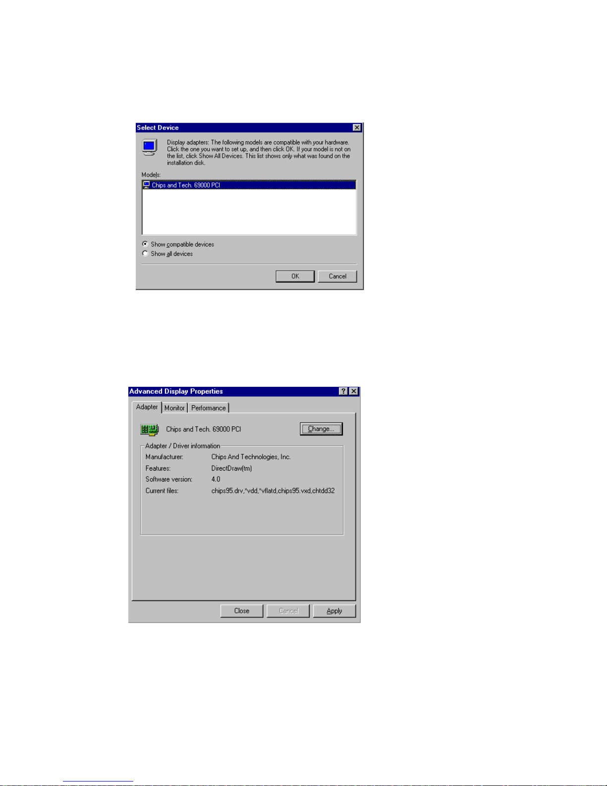
84 PCM-4896 User Manual
figure 5
figure 6
3. Once the installation is complete, the Advanced display Properties
window will reappear . Show as figure 6:
Page 97
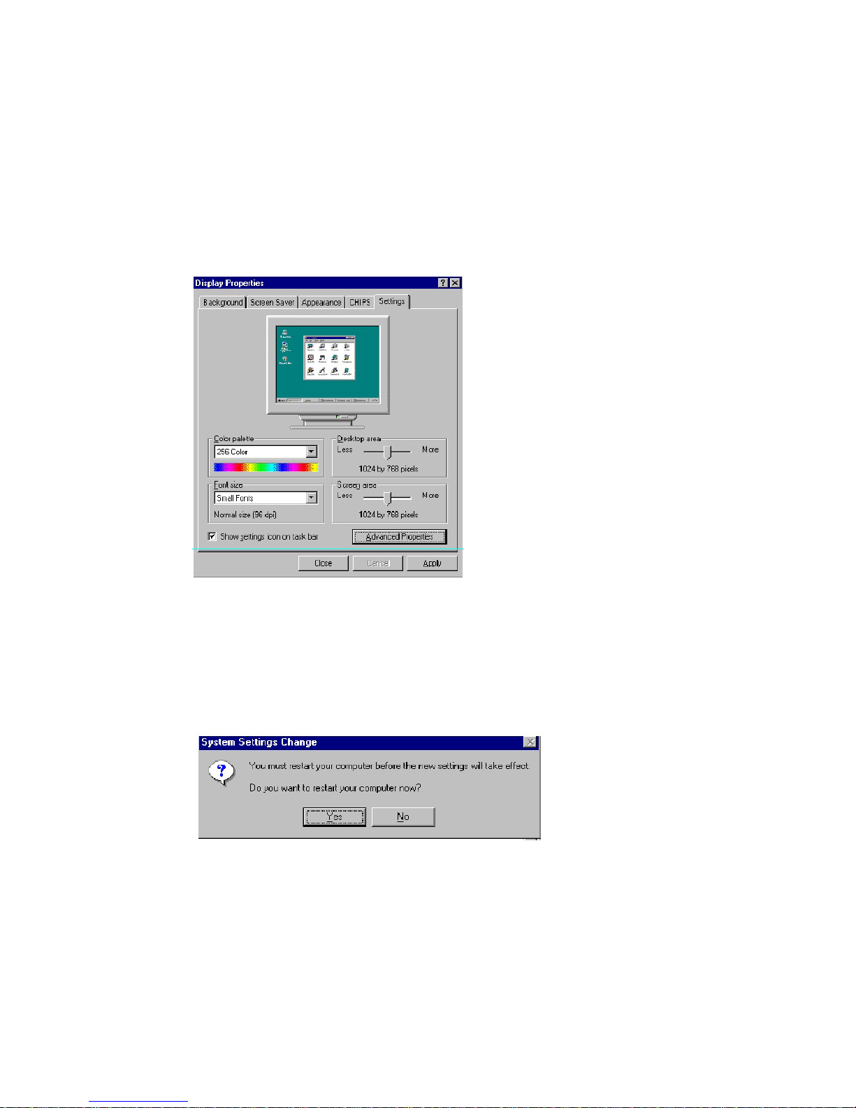
Chapter 4 Driver Installation 85
Click on close to close the window . Then the Display Properties
window will reappear . Show as figure 7:
Click on Apply. Restart the system for the new settings to take effect,
show as figure 8:
figure 7
figure 8
Page 98

86 PCM-4896 User Manual
Windows® 3.1
These drivers are designed to work with Microsoft Windows Version 3.1.
You should install these drivers through Windows.
Driver Installation
1 . Install Windows as you normally would for a VGA display . Run W in-
dows to make sure that it is working correctly .
2. Place the Supporting CD-ROM into your CD-ROM drive. In Win-
dows Program Manager, choose File from the Options Menu. Then
from the pull-down menu, choose Run. At the Command Line prompt,
type.
cd-rom:\driver\vga driver\win31\setup.exe
Press the <ENTER> key or click OK to begin the installation.
"cd-rom" : the drive letter of your CD-ROM drive
At this point the setup program locates the directory where Windows is
installed. For proper operation, the drivers must be installed in the Win-
dows subdirectory.
3. Press <ENTER> to complete the installation. Once completed, you
can find the icon Chips CPL under the Control Panel. The icon allows
you to select and load the installed drivers.
Page 99

Chapter 4 Driver Installation 87
OS/2
These drivers are designed to function with the OS/2 V ersion 4.0, 3.0 and
2.11 operating systems.
T o install this driver , do the following steps:
1. Open an OS/2 full screen or windowed session.
2 . Place the Supporting CD-ROM into your CD-ROM drive.
3 . At the OS/2 command prompt, type the following commands to
copy the files to the OS/2 drive:
cd-rom:\driver\vga driver\os2\setup.cmd
"cd-rom" : the drive letter of your CD-ROM drive
When the Setup Program is completed, you will need to perform a shutdown and then restart the system in order for changes to take effect.
A log of the information output during the install can be found
in <root>:\OS2\INST ALL\DISPLA Y .LOG
4. After restarting the system, perform the following steps:
1. Open the OS/2 System folder .
2. Open the System Setup folder .
3. Open the Display Driver Install Object.
This step will execute the Display Driver Installation (DSPINSTL)
utility program to finish installation of the new drivers.
4. When the Display Driver Install window appears, select
Primary Display and then select OK.
5. When the Primary Display Driver List window appears, select
"Chips and T echnologies 69000" from the list of adapter types,
then select OK or install the video driver .
Page 100

88 PCM-4896 User Manual
6. When the installation is complete, you will need to shut down
and then restart the system for the changes to take effect.
Make sure to remove the installation diskette before restarting
the system.
 Loading...