

Page 1

SD Card Mobile DVR
EC-MDVR-4
User Manual
Page 2

SD Card Mobile DVR – EC-MDVR-4 User Manual
1
Warning
Before installing and using please read the following
warnings carefully:
! Attention !
Please read the
instruction before
installing and using.
Keep in a safety place
for the future reference.
1. It contains electronic IC, please hold and keep in gently
2. All installing and maintaining should be hold by
professionals
3. Do not install in the place often eroding by rain and other
liquids
4. The installation and all materials must bear the fuselage
weight
5. Keep the device from heat, dust and high-intensity
magnetic filed
6. Do not put heavy things on device, any sundries around
50cm;
7. Do not flushing the device directly when clean the car;
8. Do not mixing the output batteries that not fit for the
device;
9. Do not insert your fingers and other objects into the gap
when it works
10. Do not open the device without any professional guide;
11. Do not change modules when DVR on;
Page 3

SD Card Mobile DVR – EC-MDVR-4 User Manual
2
Instruction
The manual instructed the item combine “4 Channel Video Recording”
and ”Car Black Box” Mobile DVR, Product feature, detail specification etc and
attention, the interface definition and operation etc.
4 Parts include in the Manual below sample instruction of each part.
Part 1: System Instruction
Product function, main features, outlook, accessories and application;
Part 2: Main Function
Product function instructed via Excel Table;
Part 3: Product Specification
Product working environment, Function interface, video/audio function,
working environment, operation setting
Introduce the function, features and operation mode via interface way;
Part 4: Installation and FAQ
Power Connection, Audio/Video Connection, Alarm input etc, installation
attention and FAQ
This manual may contain technical inaccuracies or typographical errors. The
contents of this manual will do not regularly updated, without prior notice. The
content of the update will join in the new version of this manual.
We could improve or update the products or procedures described in this
manual. If any manual for product description does not accord with real, all in kind
prevail.
Page 4

SD Card Mobile DVR – EC-MDVR-4 User Manual
3
Catalogue
1 System Introduction ............................................................................................................... 4
1.1 Product Feature ............................................................................................................. 4
1.2 Production Outlook ......................................................................................................... 4
1.3 Product Inner Structure .................................................................................................. 4
1.4 Panel Interface Definition ............................................................................................... 5
1.4.1 Front Panel Definition ................................................................................................. 5
1.4.2 Front Panel LED Instruction ........................................................................................ 5
1.4.3 Back Panel Definition .................................................................................................. 6
1.4.4 Back Panel Interface Definition ................................................................................... 6
1.5 IR Remote Controller ..................................................................................................... 7
2 Product Function .................................................................................................................... 8
3 Interface Operation Setting .................................................................................................. 11
3.1 User Login .................................................................................................................... 11
3.2 System Menu ............................................................................................................... 11
3.3 Menu Instruction ........................................................................................................... 12
3.3.1 Video Replay ............................................................................................................. 12
3.3.2 Record Setting .......................................................................................................... 12
3.3.3 Alarm Setting ............................................................................................................. 13
3.3.4 System Setting .......................................................................................................... 14
3.3.4.1 System Language ........................................................................................... 14
3.3.4.2 Time Setting .................................................................................................... 15
3.3.4.3 User Setting(Password Setting) ................................................................ 15
3.3.4.4 Display Setting ................................................................................................ 16
3.3.4.5 Format ............................................................................................................. 17
3.3.4.6 Configure Setting ............................................................................................ 18
3.3.4.9 Serial Port Setting ........................................................................................... 19
3.3.5 System Information ................................................................................................... 19
3.3.6 Log Search ................................................................................................................ 20
4 Installation & FAQ ................................................................................................................ 21
4.1 Power Connection ........................................................................................................ 21
4.2 Video,Audio Connection Definition .............................................................................. 21
4.3 Alarm Input & Output Connection ................................................................................ 24
4.4 FAQ .............................................................................................................................. 24
Page 5
SD Card Mobile DVR – EC-MDVR-4 User Manual
4
1 System Instruction
1.1 Product Feature
1.1 Product Feature
1.1 Product Feature1.1 Product Feature
The EC-MDVR-4 is a cost-effective and functional mobile digital video recorder spe
cially designed for vehicle surveillance and remote monitoring. It combined high speed
and performance embedded processor and embedded operating system.
Detail Features:
Detail Features:
Detail Features:Detail Features:
Industrial Level Setting, Smart MINI Size, Aviation Plug Input, Easily Installation;
Adopt H.264 Main Profile, G.726 Compression, High Resolution, small video
size;
Professional Vehicle Power Supply, adapt 8-36V wide voltage input;;
High quality Aviation Plug input/Output, easily installation and high vibration;
Support 4CH Video and 1CH Audio input, video quality adjustable;
Auto Record, Timed Record. Alarm Record; working mode to meet kinds of
requirements;
Max 64GB SD Card Supported, USB Back up;
Power-off Function, when power on, it will start recording automatic, support
Video Lost Alarm Function;
Independent Time Delay Circuit, can keep working when Car off, time can be set;
With Complete Client Software, support Real time video view, record, snap, replay
analysis;
Support Upgrade software by SD Card;
Smart MINI Size,95(W)*38(H)*115(D)mm,0.6Kg
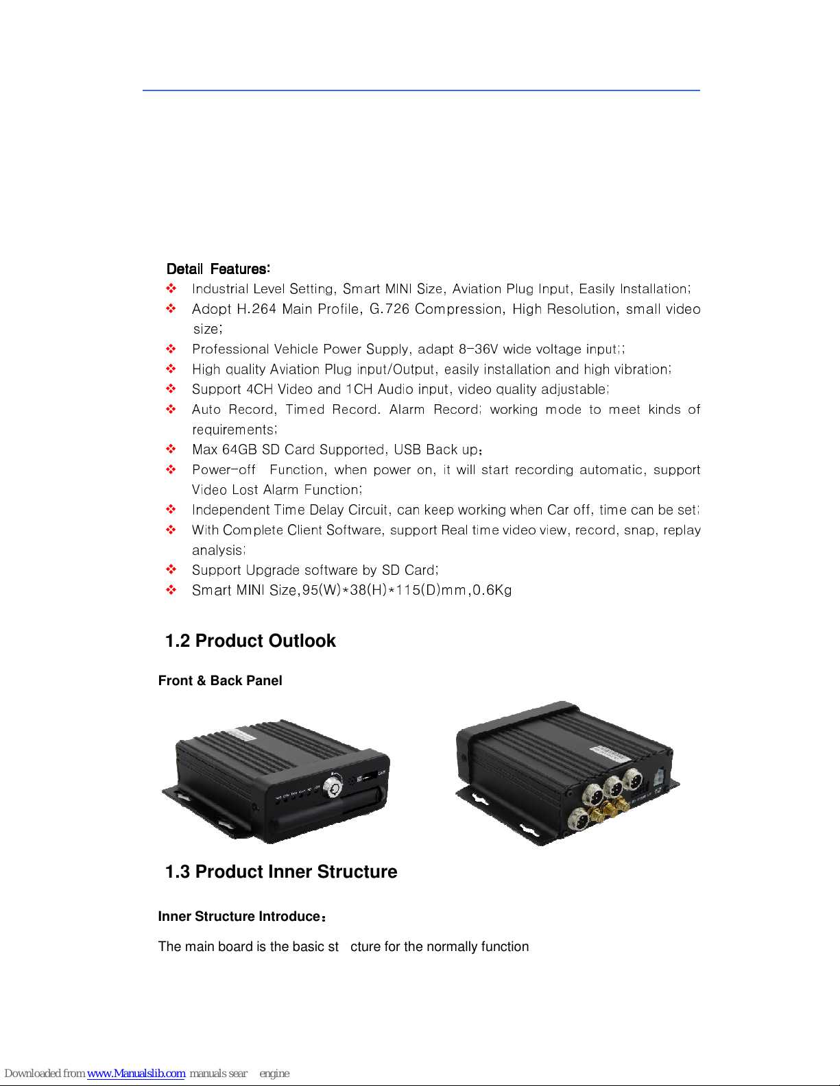
1.2 Product Outlook
Front & Back Panel
1.3 Product Inner Structure
Inner Structure Introduce
The main board is the basic structure for the normally function
::::
Page 6
SD Card Mobile DVR – EC-MDVR-4 User Manual
5
1.4 Panel Interface Definition
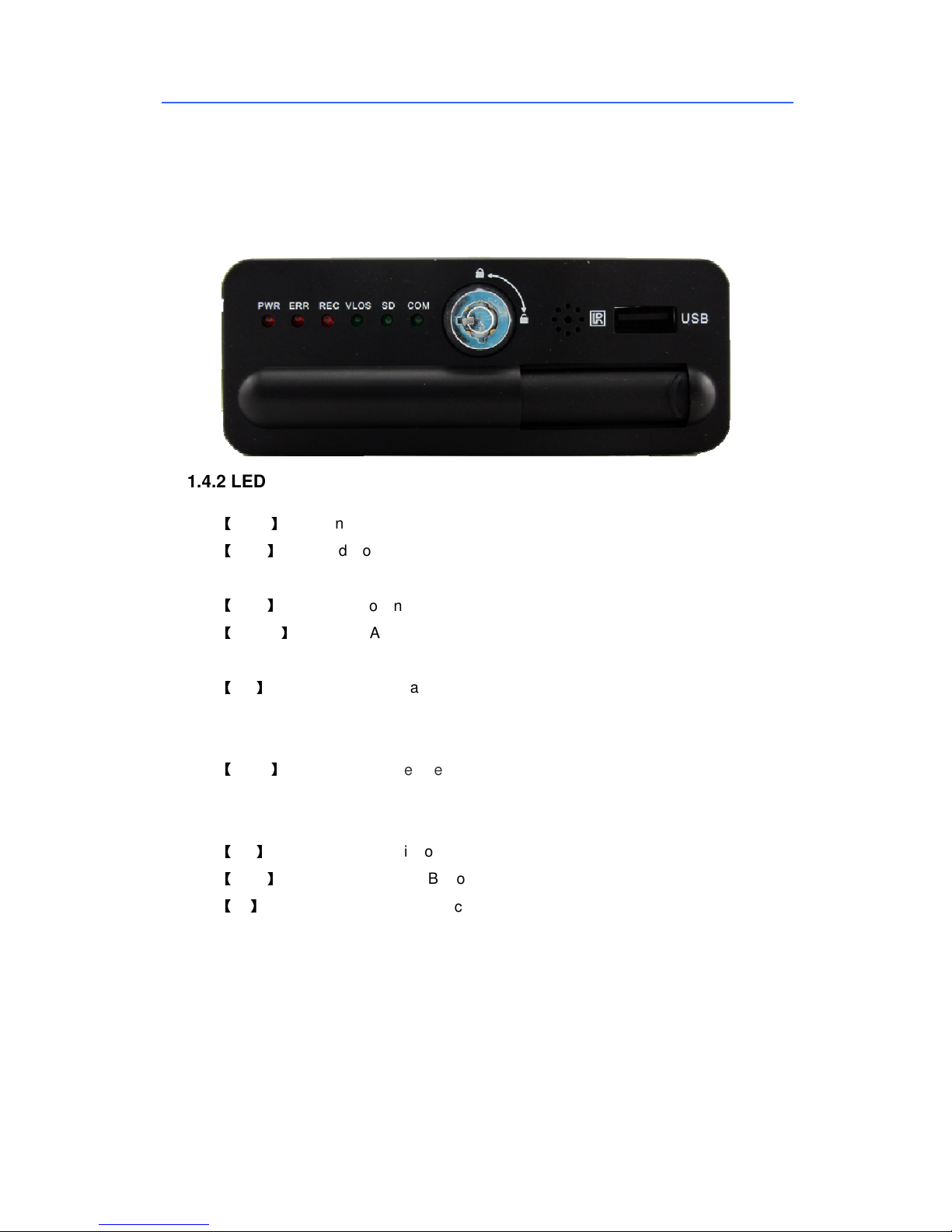
1.4.1 Front Panel Interface
Picture Below:
1.4.2 LED Indictors and instruction
【PWR】Power input indictors, LED light normally on means working normally;
【ERR】 Error indictors, LED Lights on means SD Card error, LED Lights off means
working;
【REC】Recording Working Indictors, LED light flash means recording;
【V-LOS】Video Lost Alarm, LED Lights on means 4CH Video Input lost, LED off
means video input working;
【SD】
SD Card Working Statues, LED lights on means SD Card working, LED Flash
means SD Card is Recording, LED Off means SD Card not working, can put out the SD
Card ;
【COM】Used to extend the operation condition of the wireless communication
function. A communication module are often bright, no communication module is long.
When a data transmission;
【SD】SD Card input, for video recording, Device Configure refresh and upgrade;
【USB】Interface, connect USB Storage device for recording or data backup;
【IR】Remote Controller Input: Receive Controller Signal
Page 7
SD Card Mobile DVR – EC-MDVR-4 User Manual
6
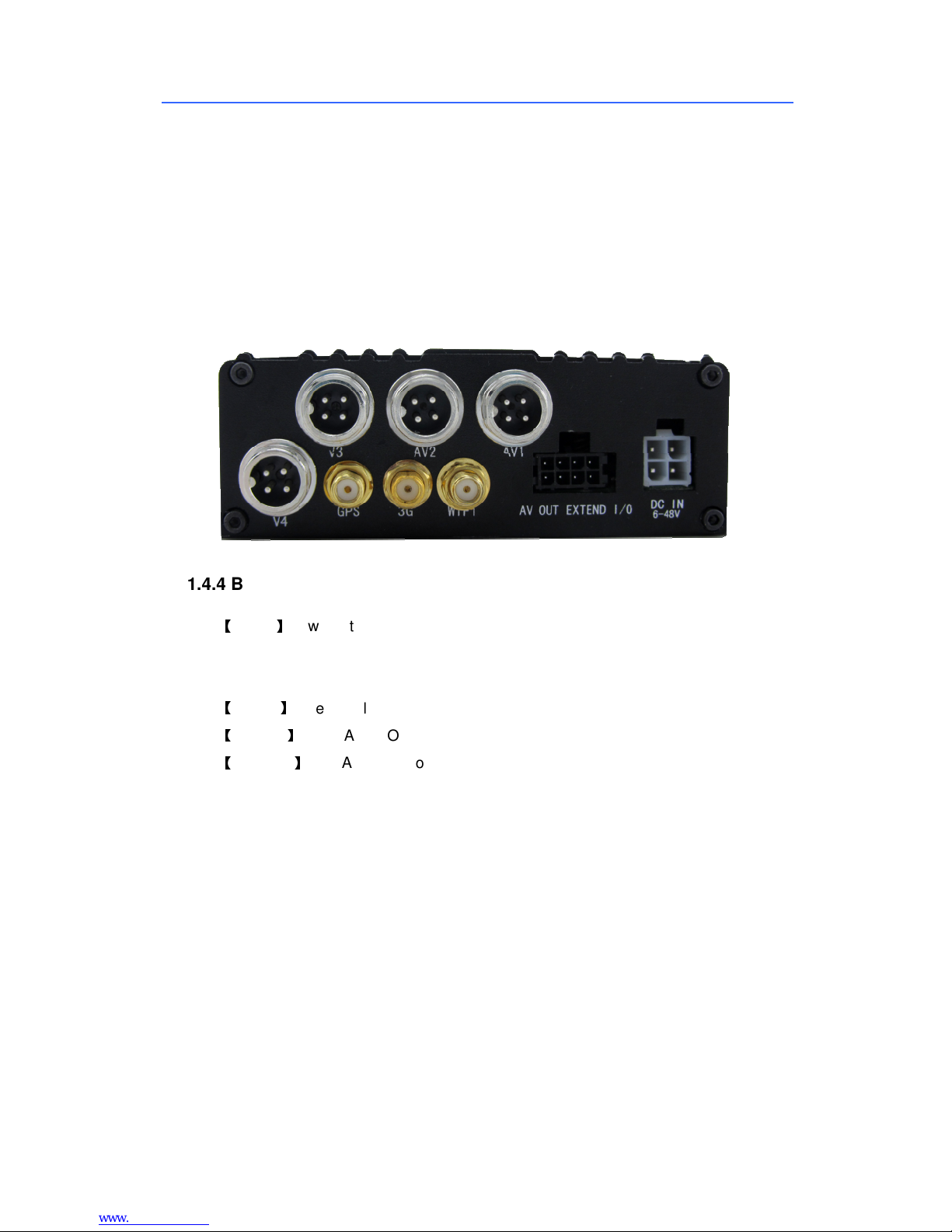
1.4.3 Back panel Interface
Picture Below
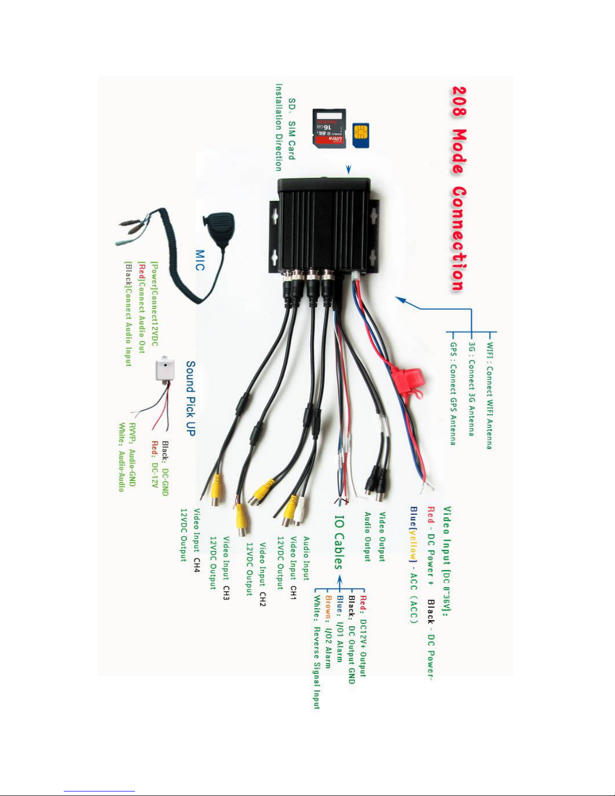
1.4.4 Back Panel Interface Definition:
【DC IN】Power Interface, in the Power line, RED LINE connect Power +,Black Line
connect Power -,Blue Cable is ACC Cable, Connect with Car ACC Line if need Timed
Recording or Power on/off;
【EX I/O】External Alarm Input/Output Interface;
【AVOUT】Video/Audio Output Interface;
【AVI 1 - 4】4CH Audio/Video Input Interface, A means Audio, V means Video;
Page 8
SD Card Mobile DVR – EC-MDVR-4 User Manual
7
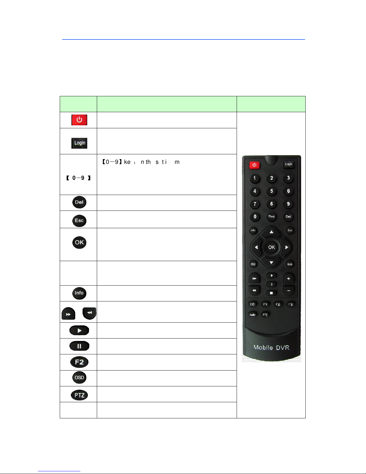
1.5 IR Remote Control
No Control Button on MDVR, need setting while IR Remote Controller
Instruction of each button on IR Remote Controller:
Key Function Picture
【【【【
0
----9 】】】】
▲▼
Start button
To enter system settings.
【0-9】key:In the setting mode, 0-9 is used to
select the number of menu items. In playback mode,
the key 1,2,3,4 to select single channel playback
and the Key 5 for 4-channel playback
Delete key, delete the Chars when typing
Back to preview interface or previous menu
Enter button: button for setting system parameter,
selecting and playing. When playback, this button
can overlay all kinds of information data (speed,
up, down, left, right left and right buttons are use for
decreasing or increasing volume
To display system info under monitoring mode
Rewind button. In play mode, press REW button to
select 2/4/8/16/,normal forward play
Other Reserved
Play button
Pause button. Pause the normal playing.
Display 3G GPS Information while monitoring
Display WIFI Information while monitoring
PTZ Control ( Or NO 9 Key)
Page 9
SD Card Mobile DVR – EC-MDVR-4 User Manual
8
Playback
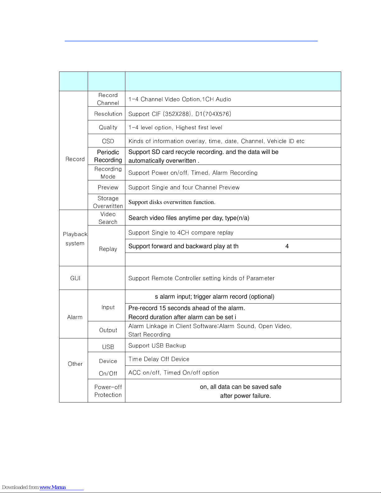
2 Product Main Function
Function
Record
Item Description
Record
Channel
Resolution
Quality
OSD Kinds of information overlay, time, date, Channel, Vehicle ID etc
Periodic
Recording
Recording
Mode
Preview Support Single and four Channel Preview
Storage
Overwritten
Video
Search
1-4 Channel Video Option,1CH Audio
Support CIF (352X288), D1(704X576)
1-4 level option, Highest first level
Support SD card recycle recording. and the data will be
automatically overwritten .
Support Power on/off, Timed, Alarm Recording
Support disks overwritten function.
Search video files anytime per day, type(n/a)
Support Single to 4CH compare replay
system
GUI
Alarm
Other
Replay
Graphical
User
Interface
Input
Output
USB
Device
On/Off
Power-off
Protection
Support forward and backward play at the speed of: x 2, x4, x8, x16.
Support alarm spot search and time search
Support Remote Controller setting kinds of Parameter
2 channels alarm input; trigger alarm record (optional)
Pre-record 15 seconds ahead of the alarm.
Record duration after alarm can be set in system
Alarm Linkage in Client Software:Alarm Sound, Open Video,
Start Recording
Support USB Backup
Time Delay Off Device
ACC on/off, Timed On/off option
With the power-off protection, all data can be saved safely and the
recording can be closed normally after power failure.
Page 10
SD Card Mobile DVR – EC-MDVR-4 User Manual
9
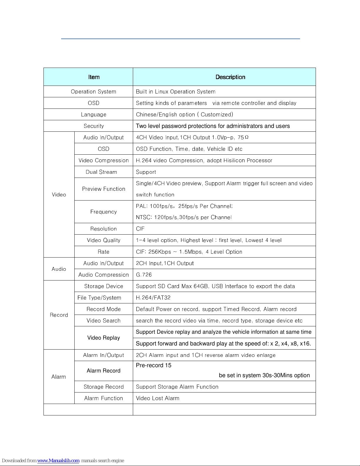
Product Parameter
Item
Item Description
ItemItem
Operation System Built in Linux Operation System
OSD Setting kinds of parameters via remote controller and display
Language Chinese/English option ( Customized)
Description
DescriptionDescription
Video
Audio
Security
Audio In/Output 4CH Video Input,1CH Output 1.0Vp-p, 75Ω
OSD OSD Function, Time, date, Vehicle ID etc
Video Compression H.264 video Compression, adopt Hisilicon Processor
Dual Stream Support
Preview Function
Frequency
Resolution CIF
Video Quality 1-4 level option, Highest level : first level, Lowest 4 level
Rate CIF: 256Kbps ~ 1.5Mbps, 4 Level Option
Audio In/Output 2CH Input,1CH Output
Audio Compression G.726
Storage Device Support SD Card Max 64GB, USB Interface to export the data
Two level password protections for administrators and users
Single/4CH Video preview, Support Alarm trigger full screen and video
switch function
PAL: 100fps/s,25fps/s Per Channel;
NTSC: 120fps/s,30fps/s per Channel
File Type/System H.264/FAT32
Record
Alarm
Record Mode Default Power on record, support Timed Record, Alarm record
Video Search search the record video via time, record type, storage device etc
Video Replay
Alarm In/Output 2CH Alarm input and 1CH reverse alarm video enlarge
Alarm Record
Storage Record Support Storage Alarm Function
Alarm Function Video Lost Alarm
Support Device replay and analyze the vehicle information at same time
Support forward and backward play at the speed of: x 2, x4, x8, x16.
Pre-record 15 seconds ahead of the alarm.
Record duration after alarm can be set in system 30s-30Mins option
Page 11
SD Card Mobile DVR – EC-MDVR-4 User Manual
10
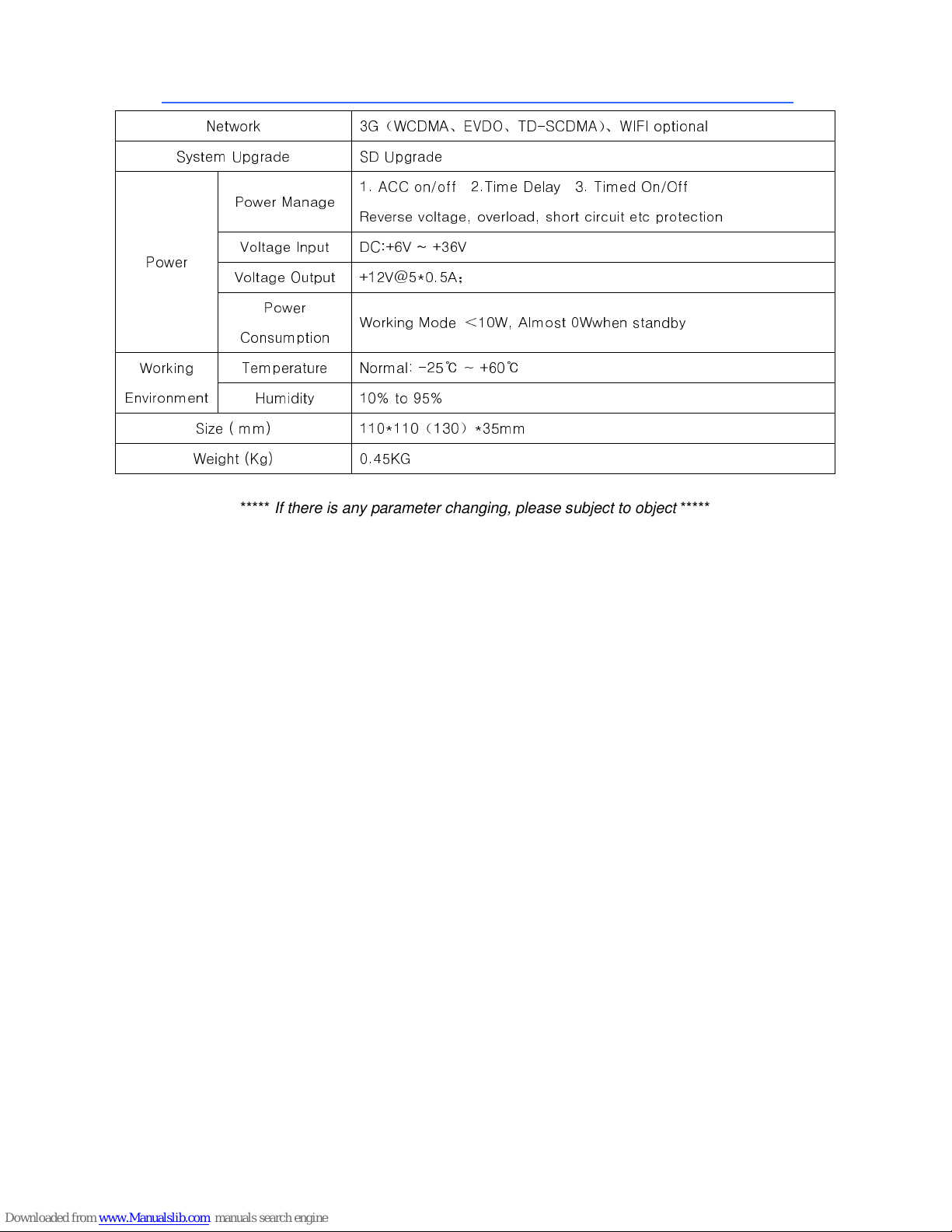
Network 3G(WCDMA、EVDO、TD-SCDMA)、WIFI optional
System Upgrade SD Upgrade
Power
Working
Environment
Size ( mm) 110*110(130)*35mm
Weight (Kg) 0.45KG
Power Manage
1. ACC on/off 2.Time Delay 3. Timed On/Off
Reverse voltage, overload, short circuit etc protection
Voltage Input DC:+6V ~ +36V
Voltage Output +12V@5*0.5A;
Power
Working Mode <10W, Almost 0Wwhen standby
Consumption
Temperature Normal: -25℃ ~ +60℃
Humidity 10% to 95%
***** If there is any parameter changing, please subject to object *****
Page 12
SD Card Mobile DVR – EC-MDVR-4 User Manual
11
3 GUI
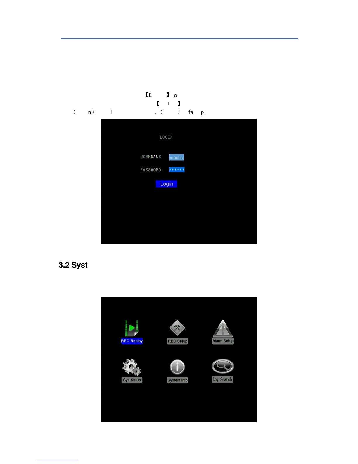
3.1.log in
When password shut off, Press【ENTER】come into the main menu after the device power on
When password button open, Press【ENTER】and enter the id and password then log in
(admin)default password 111111,(USER)default password 000000
3.2 System Main Interface
The main interface will be displayed on the screen when you login successfully, it contains the
following
Page 13
SD Card Mobile DVR – EC-MDVR-4 User Manual
12
3.3 Menu Introduction
3.3.1 Video Playback
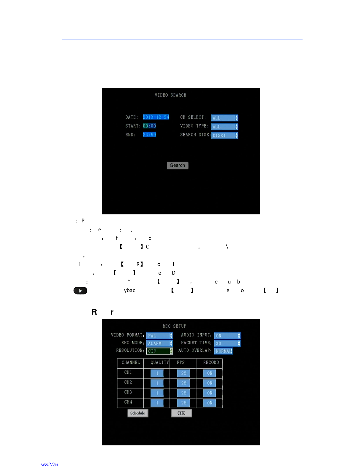
choose playback button, then come to video search as the following
“Date”:Press the date you want
“T ime start”:default 00:00, can be setted
“T ime Complete”: default 23:59, can be setted
“Channel Choice”: Use【ENTER】Choose the Channel:CH1\CH2\CH3\CH4, all Channel display
defaulted。
“Recording type”:Press【ENTER】to choose all videos or alarm video. System default all videos
“Disk choose”:Press【ENTER】to choose the DISK1\U disk
“Research”:Press “research” and press【ENTER】key,enter the picture below
Press choose the playback videos, press【ENTER】key to play the video, Press 【ESC】to return.
3.3.2 Recording Setting
Page 14
SD Card Mobile DVR – EC-MDVR-4 User Manual
13
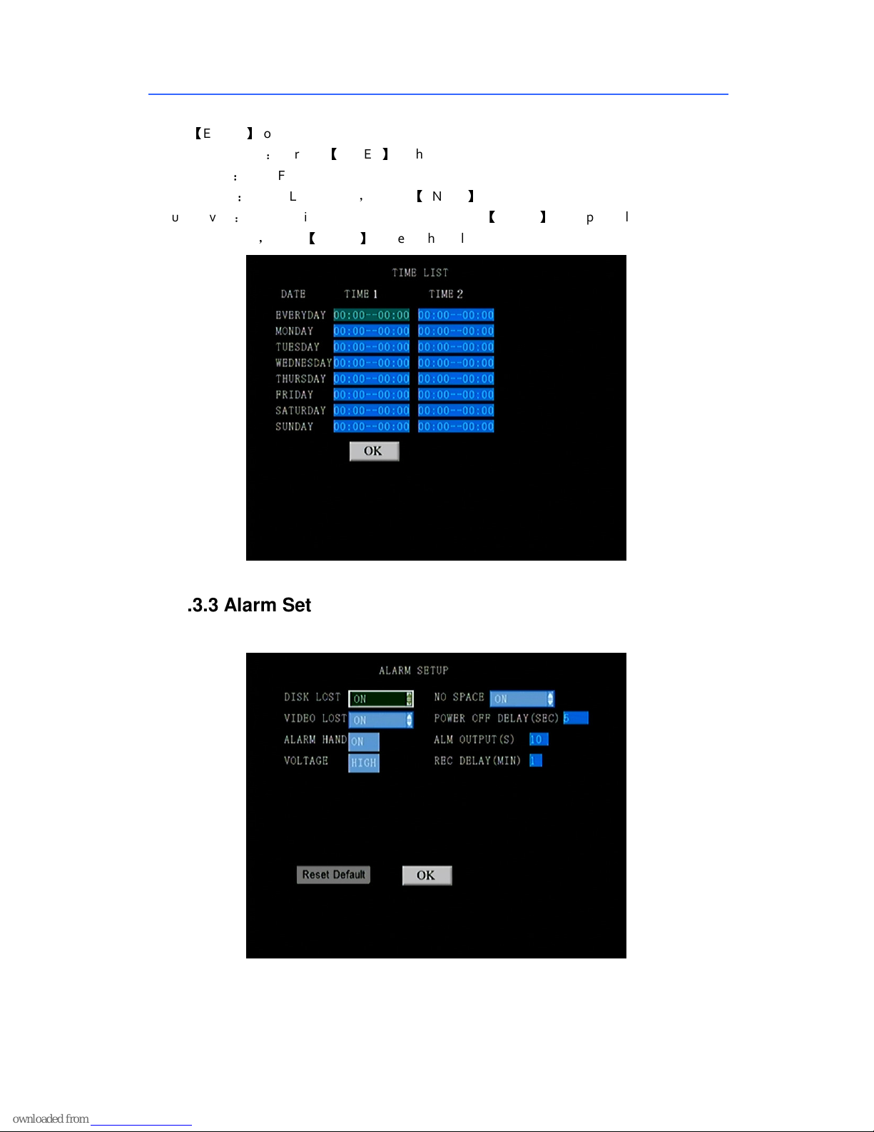
Press【ENTER】to choose PAL/NTSC
“Recording Mode”: Press 【ENTER】to choose Auto/Time/Alarm Recording
“Resolution”:D1/CIF
“Audio Input”:LINE1\LINE2 input, Press【ENTER】
“Auto Cover”:used for video auto covered or not, press【ENTER】 for optional
“Click ” t ime list”,Press【ENTER】come to the following set
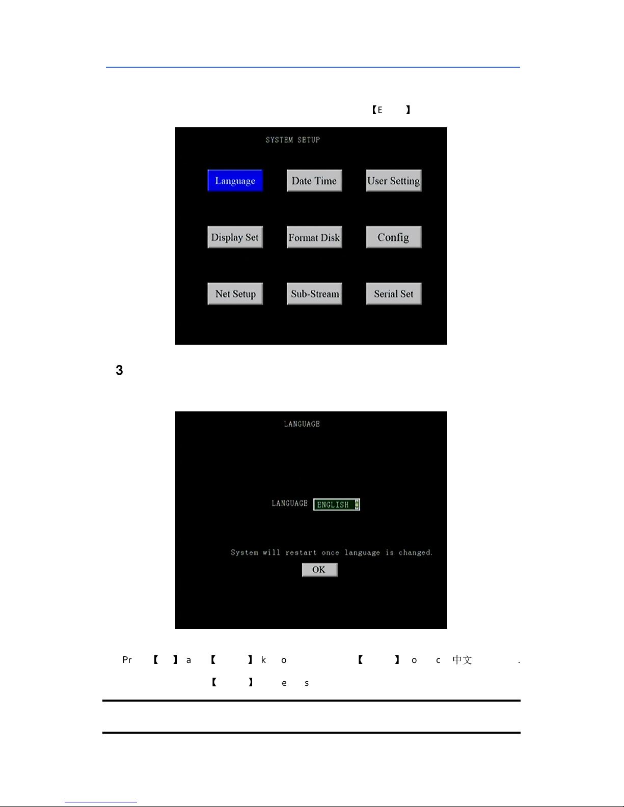
3.3.3 Alarm Setup
Set the data of relevant alarm input/output and alarm recording
Page 15
SD Card Mobile DVR – EC-MDVR-4 User Manual
14
3.3.4 System Setup
Use the direction key to choose system setting menu then click【ENTER】, enter the following GUI
3.3.4.1 LANGUAGE
This menu is used to switch the system language.
Press 【UP】 and 【DOWN】 key to select and press【ENTER】 to switch “中文\ENGLISH”.
Select “SAVE” and press 【ENTER】to save the settings.
NOTE: System will restart when changing the language.
Page 16
SD Card Mobile DVR – EC-MDVR-4 User Manual
15
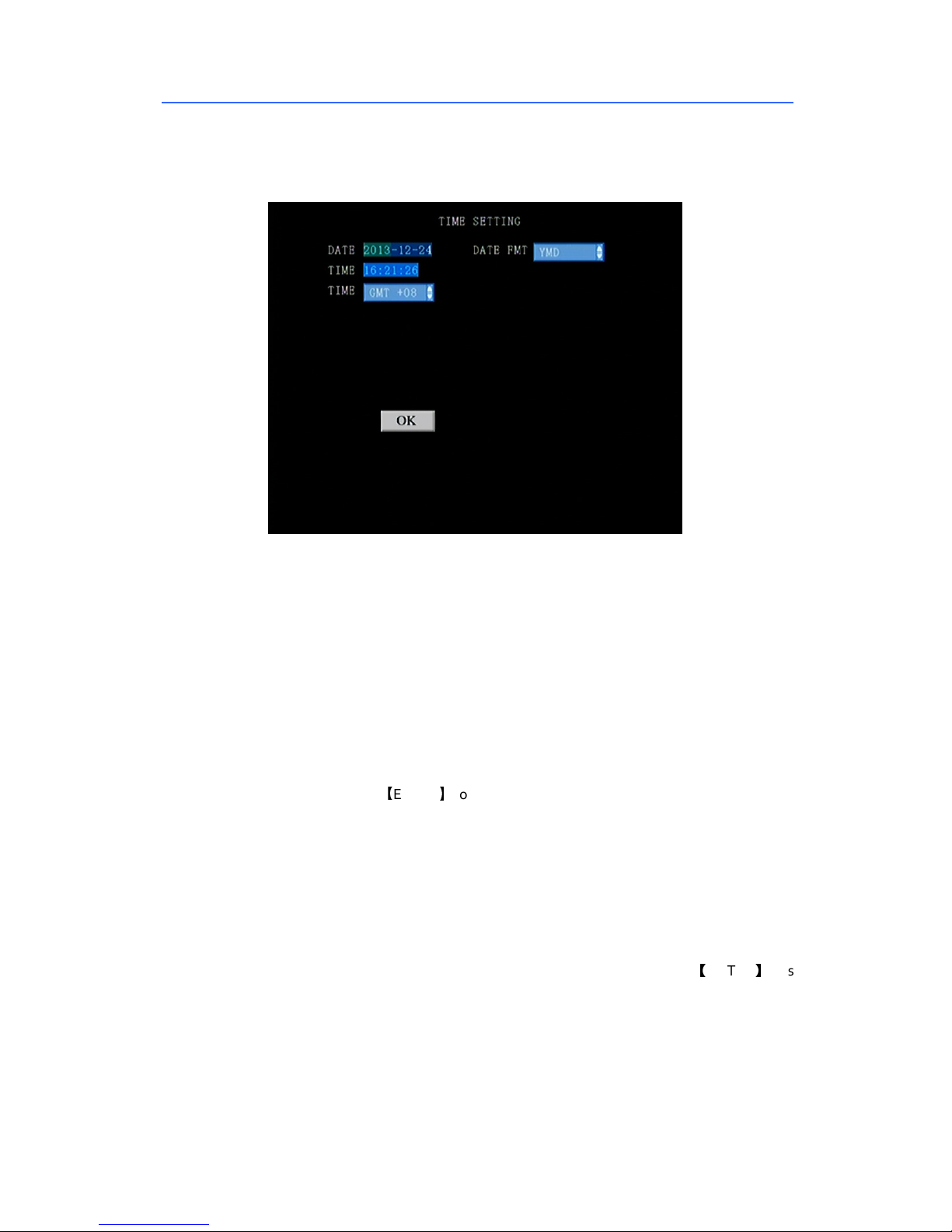
3.3.4.2 DATE & TIME
This menu is used to set the date and time of system.
DATE: Press the digit keys to setup the date, press direction key for enter, press digital
keys for modify.
DATE TYPE: year/month/day, day/month/year, month/day/year. Press [ENTER] to select.
TIME: Press the digit keys to setup the clock, press direction key for enter, press digital
keys for modify.
Time Zone: GPS module will check time zoon automatically if DVR with GPS after setting
time.
Select “SAVE” and press 【ENTER】to save the settings.
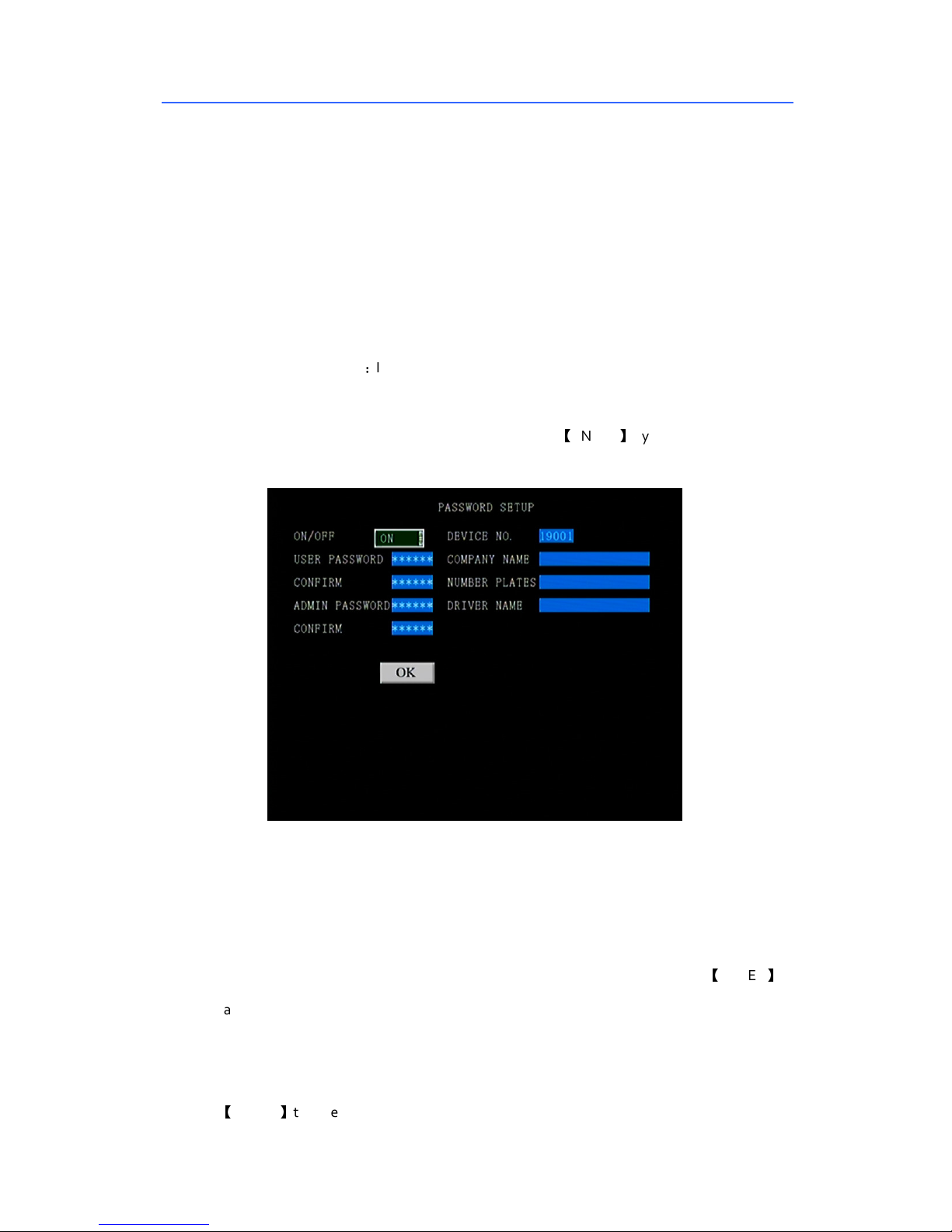
3.3.4.3 USER SETTINGS (PASSWORD SETTINGS)
PASSWORD ENABLE: in order to access the setup menu with a password, select |ON|,
otherwise select |OFF| to disable password. Direction keys for entering and 【ENTER】keys
for changing.
Device No: in order to set up the No. Of 3G mobile DVR, thus can distinguish it when
several device in the same surface at the same time. Press digital keys to change.
USER PASSWORD: Users can search and play video records but cannot modify parameters
Page 17
SD Card Mobile DVR – EC-MDVR-4 User Manual
16
with this password. Press direct ion keys to enter into, press digit keys to modify the
password
CONFIRM PASSWORD: confirm the user password, Press direction keys to enter into,
press digit keys to modify the password
ADMIN PASSWORD: Users are endowed full rights with this password, such as search, play
or modify parameters. Press direction keys to enter into, press digit keys to modify the
password.
CONFIRM PASSWORD:It is used to confirm admin password. Press direct ion keys to enter
into, press digit keys to modify the password.
INC NAME, VEHICLE NUMBER, DRIVER NAME: Press 【ENTER】key to select and enter the
keyboard menu, move the cursor to select letters.
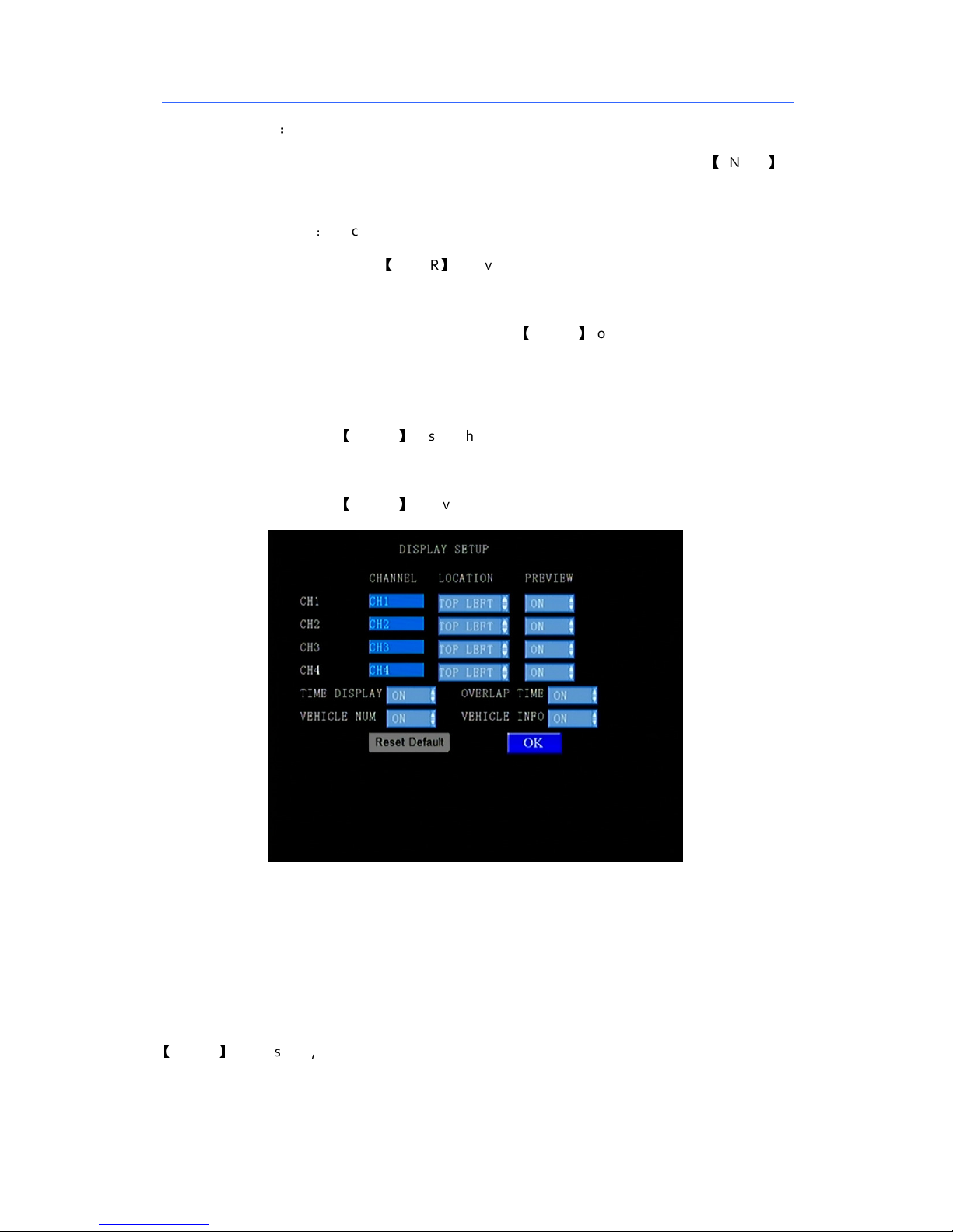
3.3.4.4 DISPLAY SETTINGS
CHANNEL NAME: To display the channel name. User can set four channels individually.
Press direction keys to enter this item and modify. Select “SAVE” and press 【ENTER】to
save the settings.
LOCATION: To select the display position of channel name. User can set four channels
individually. Press direction keys to enter this item and modify. Select “SAVE” and press
【
ENTER】to save the settings.
Page 18
SD Card Mobile DVR – EC-MDVR-4 User Manual
17
PREVIEW: To enable or disable preview function. User can set four channels individually.
Press direction keys to enter this item and modify. Select “SAVE” and press 【ENTER】to
save the settings.
TIME DISPLAY:Clock display: to enable or disable clock display in the preview mode.
Select “SAVE” and press 【ENTER】to save the settings.
TIME OVERLAY: To select time overlay function enable or not. Press direction keys to enter
this item and modify. Select “SAVE” and press 【ENTER】to save the settings.
select DEFAULT to restore the default sett ings.
Vehicle Number OVERLAY: In order to overlay the vehicle number in recording. Select
“SAVE” and press 【ENTER】to save the settings.
Tracking OVERLAY: In order to overlay the tracking information in the recording. Select
“SAVE” and press 【ENTER】to save the settings.
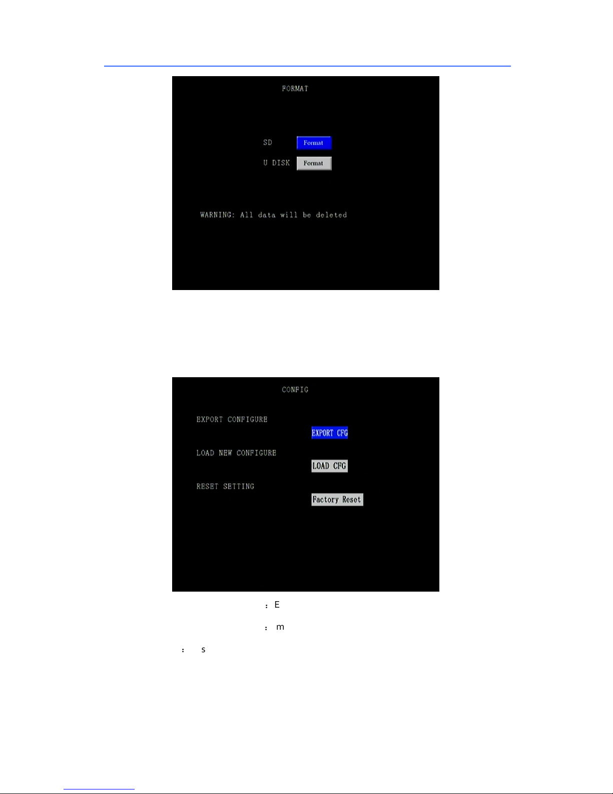
3.3.4.5 DISK FORMAT
Disk management is used to format the specified storages.
Format: Press direction keys to select the storage equipment you need to format. Press
【
ENTER】key to select, system will pop up the following menu as below.
Note: Format will delete all data in the SD card/HDD.
Page 19
SD Card Mobile DVR – EC-MDVR-4 User Manual
18
3.3.4.6 CONFIGURATION
Restore the default settings, import and export the machine configurations.
EXPORT CURRENT SETTINGS:Export the all configurat ion of the machine into SD Card.
IMPORT CURRENT SETTINGS:Import the configuration of SD Card into the mobile DVR.
RESTORE:Restore default settings. This operation will release all setting of the mobile
DVR.
Notes: For many device, same setting, please use export current settings and import
current settings .
Page 20
SD Card Mobile DVR – EC-MDVR-4 User Manual
19
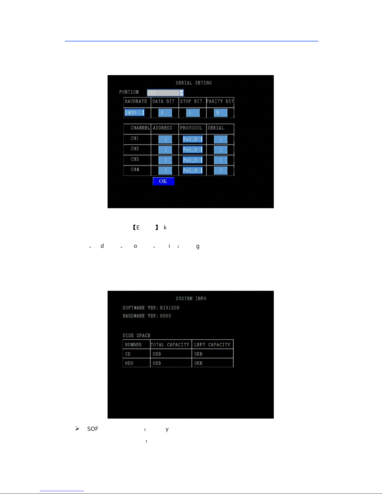
3.3.4.9 Serial set
“serial port”: can proceed function extension by configurat ing the serial port. Control PTZ, data
transmission, etc. Press 【ENTER】 key.
“Baud rate”, ”data bit”, “stop bit”, “parity bit”: configure serial port parameters
“Channel”、“Address”、“Protocol”、“serial”:configure PTZ parameters in every channel
When in correct configuration, PTZ control and data transmission can proceed
3.3.5 SYS INFO
SOFTWARE VERSION:Display current local firmware version.
HARDWARE VERSION:Display current local hardware version.
Page 21
SD Card Mobile DVR – EC-MDVR-4 User Manual
20
SD CARD CAPACITY: Displaying the total capacity and remaining capacity of SD Card(s).
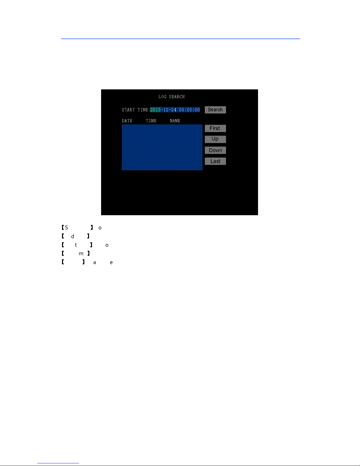
3.3.6 Log Search
Manage and record the host alarm, including date, time and name
【
Start Date】For log search, press the digit keys to setup.
【
End date】For log search, press the digit keys to setup.
【
Start time】For log search, press the digit keys to setup.
【
End time】For log search, press the digit keys to setup.
【
Search】Search the all log information occurred between “Start time” and “End time”. Press Enter
key to select.
Page 22
SD Card Mobile DVR – EC-MDVR-4 User Manual
21
Negative
Negative
4 Device Installation and FAQ
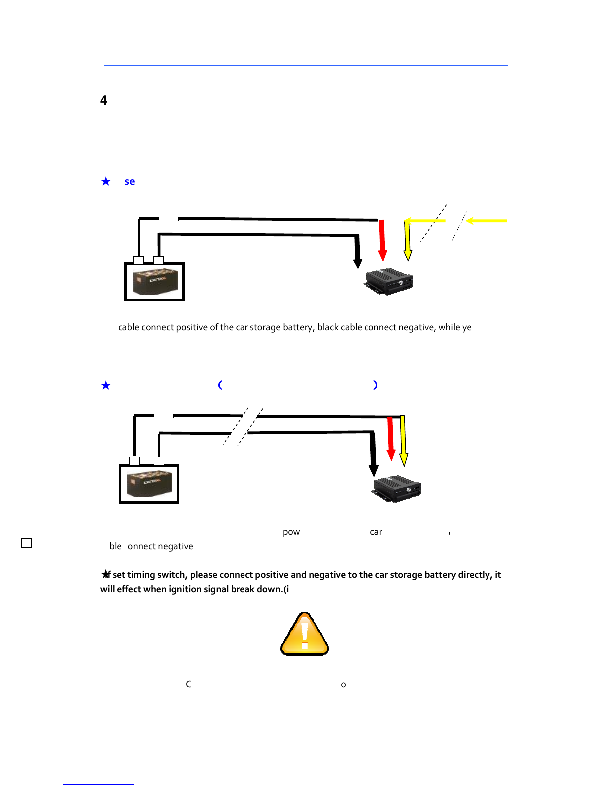
4.1 Power supply connection
The input voltage is DC 8V - 36V
★
Use ignition switch to control video record delay time working
D
C IN (POSITIVE) Red
Positive
DC OUT (NEGATIVE) Black
Fuse box
Red cable connect positive of the car storage battery, black cable connect negative, while yellow
cable connect independent ignition switch or independent positive.
★
Switch connection
((((
Indoor test also adopt this way
DC OUT (NEGATIVE) Black
Positive
Fuse box
Red cable and yellow cable together connect power positive of the car storage battery, while black
cable connect negative
★
If set timing switch, please connect positive and negative to the car storage battery directly, it
will effect when ignition signal break down.(if set timing, it will invalid when power off )
DC IN (POSITIVE) Red
))))
Signal in (yellow)
Signal in (yellow)
1. The recorder is DC power supply; please attention the positive and negative polar.
2. The voltage is 7V~48V.Do not insert voltage that beyond this range. Under low voltage the
recorder doesn’t work, under high voltage will be harm to the recorder.
! Attention !
Page 23
SD Card Mobile DVR – EC-MDVR-4 User Manual
22
3. Please make sure the recorder is connected with the car power directly. Do not connect with the
generator, the instantaneous voltage will harm to the recorder.
4. The initial power will beyond 30W when the DVR connect with the Camera (the consu
med power is different due to the connect with different device, the power supply must be
yond 30W.
5. The power cables must can stand beyond 60W.(For example, when
the output voltage of car is 12V,the power cables must can bear 5A or more.
6. Please put the cover on the cables, the cover must be wear-resistant, heat-resistant, water-proof,
grease-proof, in case of short circuit and open circuit.
7. Please install a 10A fuse box near the battery output positive polar for fear of the short circuit will
damage the power supply.
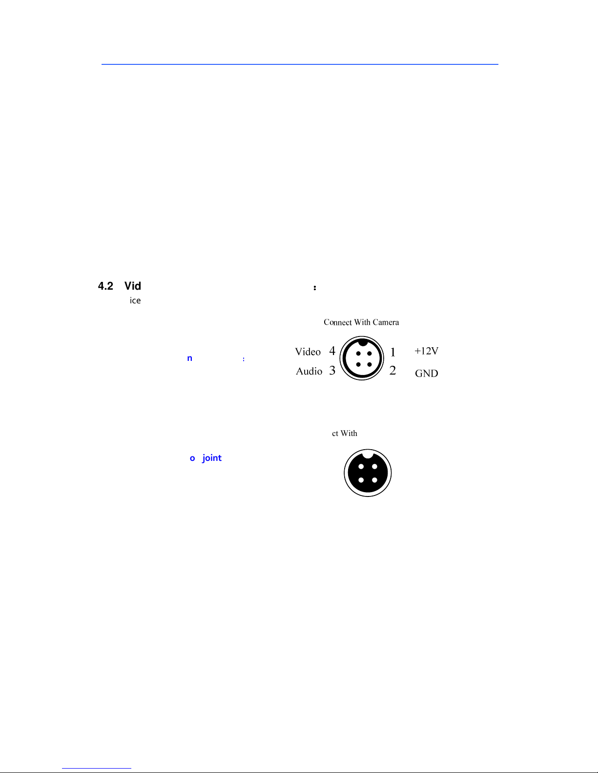
4.2 Video, Audio Connection Defination
The device support channel AV1~ AV4.The aviation joint can adapt severe environment in the car
Host aviation joint define:
Camera aviation joint define
::::
Connect With Display or Device
+12V
GND
1
2
4
3
Video
Audio
Page 24
SD Card Mobile DVR – EC-MDVR-4 User Manual
23
Page 25
SD Card Mobile DVR – EC-MDVR-4 User Manual
24
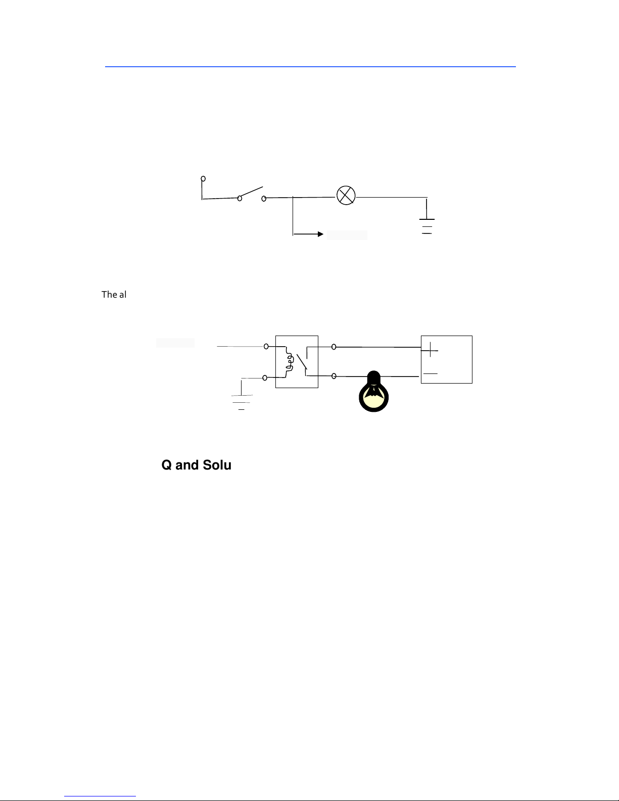
4.3 Alarm in/out mode
The device supports 2 alarm inputs. The alarm input detection use
level detection; it can connect with all kinds of vehicle driving state, like brake, turn horn, ect. The
following is the brake detection
diagram. When the braking vane is down, the device can detect the high level or the low level.
+12V
The alarm output use level output, the drive capacity is 200MA.If the device power is big, please
insert relays. The alarm output diagrams are as following
Alarm Out
shoe brake
stop lamp
Alarm In
12V
4.4 FAQ and Solutions
Q: What should you do if the products problems can not solved by ourself.
A: Record the model and software versions number, report our engineers detailed
problem, more detailed will be more convenient for us to analysis and deal with.
Q: Device cannot make a record successfully.
A: 1.Check the device if is opened. Check the device input power, Check the power
cable , If it is right connect ion, if the ground wire is connect with the storage battery,
If the fuse of the power wire is no problem; and check if the red and yellow line(device
power supply) power supply is no problem, if there are only one line supply power, the
device can not be opened.
2. Check if the monitor is powered-up, and if the monitor video is switch to AV and
corresponding channel status.
3. Check the connection state of the device video input wire and the monitor.
Page 26

SD Card Mobile DVR – EC-MDVR-4 User Manual
25
Q: The device is restarting all the time.
A: 1.If the device voltage is enough or not, may it didn’t up the device start ing
voltage caused restart.
2. HDD/SD Card problem caused device cannot be start, take down the storage device
and starting up can judge it.
Q: If the video input interface of the device and camera is different.
A:The DVR is using 4 needle type port, the camera is BNC port or Aviation, if it is
different, please use the X-over to connect, or connect according to the DVR Line
sequence definition
Q: The device was opened, HDD was installed, but the device cannot record
successful.
A: 1.Check the HDD/SD Card was formatted or not, the unformatted HH/SD Card
cannot be used. Enter into the Main Menu – System Setup – Formatting the new
installed HDD/SD Card.
2. If the recording channel is closed, if set the t iming recording, it cannot recording
when it beyond the period of timing recording.
3. If the HDD is connect well, if the HDD/SD light is on.
Q: Video files lost, or there is no video files at a certain period time.
A: 1. Analysis the lost video and ensure the lost t ime period.
2. Confirm if the DVR was opened at that time, such as crashed midway park, loading
and unloading ect. And the device didn’t set the delay recording
Q: Cannot control the PTZ, cannot rotate to all direction.
A: If the agreement and Baud rate of the PTZ is sett ing right, if the address code is
corresponding, if the video channel is setting to max when control the PTZ. Like if is
control the first channel, then must set the first channel image to be max.
Other quest ions:
Q: Video Lost in certain channel?
A: Possible reasons are as follows
1. This channel has no video input
2.The camera of this channel breaks down or work abnormality
3.If the camera takes an electricity power from the equipments directly, may be the
equipment’s electric voltage isn't enough to make camera work as usual;
Page 27

SD Card Mobile DVR – EC-MDVR-4 User Manual
26
d) The cable that links this channel has problem
Q: Can’t playback files on PC successfully?
A: Possible reason is as follows:
1. Have never chosen a record file or document path; please choose the path that
records file first before playback.
2. Local record files was damaged;
Q: Remote control not works?
A: Probably of the reasons are as follows:
1.The remote control didn't pack battery;
2.2.The remote control damages;
3.Device damages.
 Loading...