

Page 1
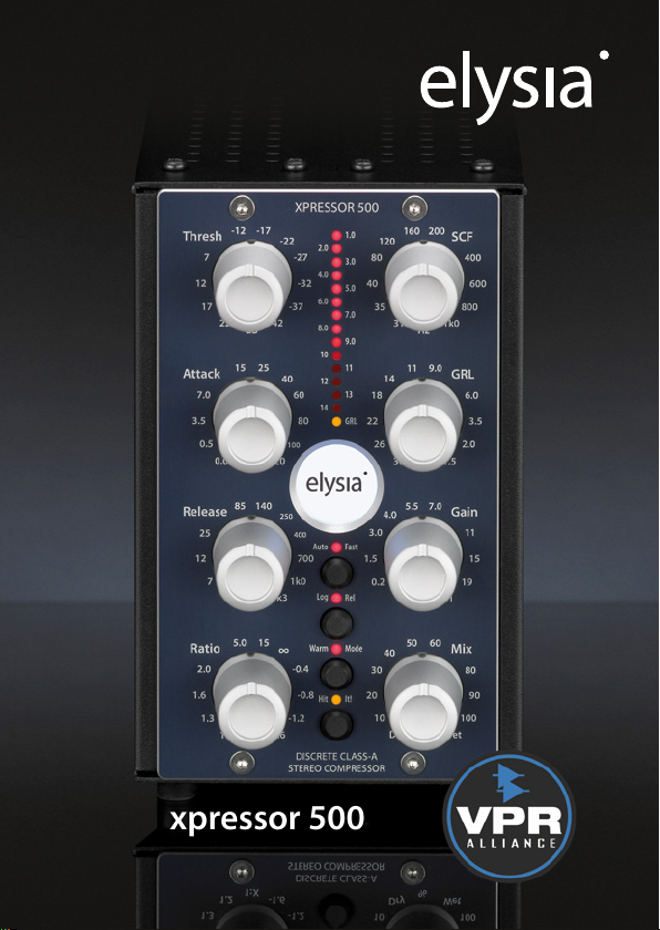
xpressor 500
Page 2

Welcome to compressor wonderland!
First of all, we would like to thank you for picking the xpressor
500 as your new dynamics tool - a very good choice indeed.
We believe this module is the most versatile stereo compres-
sor available in API’s 500 series format. With its many unique
features taken from our agship products, you not only get
great compression, but an amount of control on processing
which has yet to be experienced elsewhere.
No matter if you want to set and forget or plunge deep into
the secrets of compression, the xpressor 500 is for you. Its dis-
crete audio path running in constant class-A mode provides
a superior audio quality which combines a clear and open
sound with a good lot of punch.
Stereo buss compression, processing single signals, approach-
ing dynamics in creative ways – the xpressor 500 shines in
many dierent applications. Best of elysia? You got it!
Compatibility . . . . . . . . . . . . . . . . . . . . . . . . . . . . . . . . . . . . . . . . . . . . . .3
Installation . . . . . . . . . . . . . . . . . . . . . . . . . . . . . . . . . . . . . . . . . . . . . . . .3
Controls . . . . . . . . . . . . . . . . . . . . . . . . . . . . . . . . . . . . . . . . . . . . . . . . . . .4
Connectors . . . . . . . . . . . . . . . . . . . . . . . . . . . . . . . . . . . . . . . . . . . . . . . .6
Auto Fast . . . . . . . . . . . . . . . . . . . . . . . . . . . . . . . . . . . . . . . . . . . . . . . . . .7
Log Release . . . . . . . . . . . . . . . . . . . . . . . . . . . . . . . . . . . . . . . . . . . . . . . .8
Warm Mode . . . . . . . . . . . . . . . . . . . . . . . . . . . . . . . . . . . . . . . . . . . . . . .9
Negative Ratios . . . . . . . . . . . . . . . . . . . . . . . . . . . . . . . . . . . . . . . . . . 10
Gain Reduction Limiter . . . . . . . . . . . . . . . . . . . . . . . . . . . . . . . . . . . 11
Appendix . . . . . . . . . . . . . . . . . . . . . . . . . . . . . . . . . . . . . . . . . . . . . . . . 12
Deutsches Handbuch . . . 16 Manuel Français . . . 30
2
Page 3
Compatibility
The xpressor 500 is a module to be installed into an API 500 se-
ries compatible rack frame (not included). It needs the power
supply and the audio connectors provided by this frame and
does not function stand alone.
The current consumption is 125 milliamperes at +/- 16 volts
DC. This is actually more than many other 500 series modules
consume as a result of the discrete class-A design of the xpres-
sor 500’s audio path.
Most API 500 compatible racks will meet this requirement
without problems, but there might be a limitation of how
many units can be installed in a single rack. In case of doubt
please check with the manufacturer of your specic rack.
Installation
Just follow these easy steps to install the xpressor 500 module:
1. Switch your API 500 series compatible rack o and discon-
nect the power cable from mains.
2. Insert the module into two free slots of your rack. Make sure
both PCB connectors match with the rack connectors.
3. Gently push the module in place - do not use any extensive
force here!
4. Tighten the front panel with four screws provided by your
rack manufacturer.
5. Connect your XLR audio cables (see page 6 for more info)
and apply power to your rack.
And this is already it. Have lots of fun with your xpressor 500!
3
Page 4
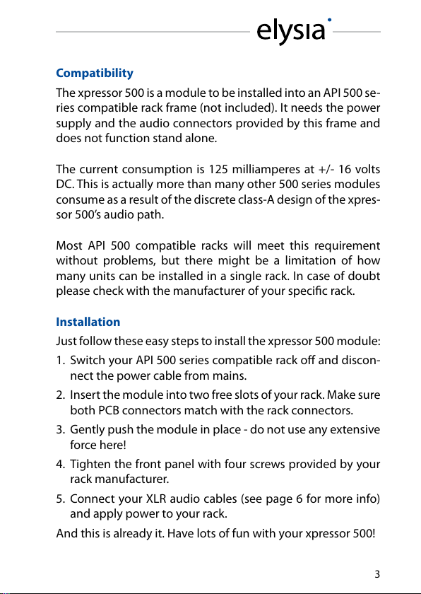
Controls
Threshold (Thresh): The operating point of the compres-
sor. If the input level exceeds the value set with this controller,
the compression process will start.
Attack: The transient response of the compressor. It deter-
mines the time the xpressor 500 needs to reach 10 dB of gain
reduction.
Release: The return phase of the compressor. It controls
the period of time between the input signal falling below the
threshold and the xpressor 500’s return to unity gain.
Ratio: The relation between the input level and the output
level. As a specialty of the xpressor 500, even negative ratios
can be set here. (p. 10)
4
Page 5
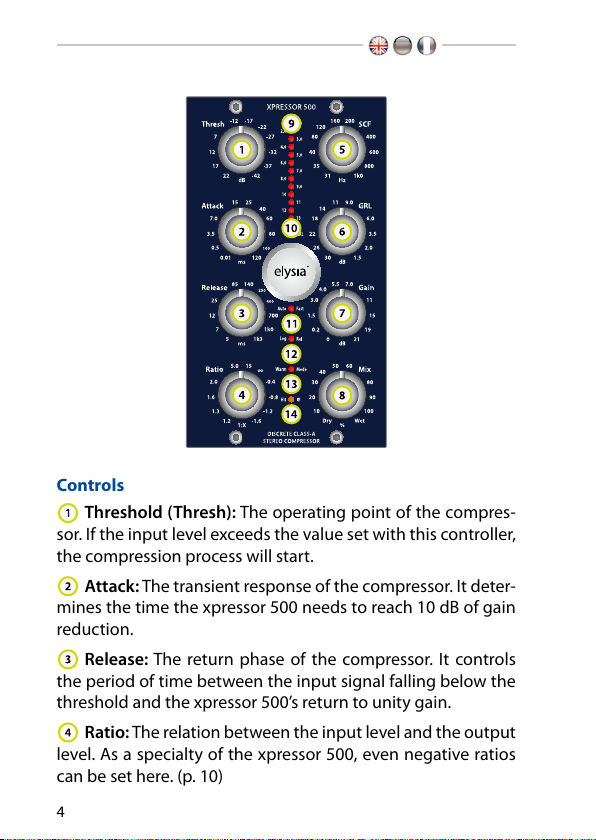
Sidechain Filter (SCF): A tunable low cut lter in the side-
chain of the xpressor 500 avoids overcompression and pump-
ing when there is a lot of low end energy in the mix.
Gain Reduction Limiter (GRL): Restricts the control volt-
age. This innovative limiter is not placed in the audio path as
usual, but in the control circuit of the compressor. (p. 11)
Gain: The make-up gain of the xpressor 500. This control-
ler compensates for the loss in gain caused by the compres-
sion process.
Mix: The direct and the compressed signal can be blended
in any desired relation by simply turning the mix controller.
Onboard parallel compression!
Gain Reduction Meter: The display for the gain reduction
process. Shows the amount of compression measured in dB as
an visual support for the acoustic events.
GRL LED: indicates Gain Reduction Limiter activity. If this
LED is on, incoming signals will be held at the GR limit instead
of being compressed any further. (p. 11)
Auto Fast: A semi-automation. This function shortens the
attack time automatically on fast and loud signal impulses and
then returns to the value set with the controller. (p. 7)
Log Release (Log Rel): This alternative release curve fol-
lows a logarithmic course instead of the standard linear prog-
ress which results in a very gentle kind of compression. (p. 8)
Warm Mode: The xpressor 500 oers a second switchable
sound avor by altering its frequency spectrum, harmonics
and transient response. (p. 9)
Hit It! Activates the xpressor 500 (LED on) or deactivates it
with a hardwire bypass (GR meter remains active).
5
Page 6

Please note that in stereo operation both channels are always
processed by one single control voltage generated from a mix
of both signals. This means you should only compress adequate
stereo material like sum signals in this mode - dissimilar sig-
nals like a bass drum in one channel and a synth pad in the
other will not give you the intended ‘dual mono’ results.
Connectors
Audio outputs (+4 dBu)
Pin assignment balanced: 1 ground 2 hot (+) 3 ground
Pin assignment unbalanced: 1 ground 2 hot (+) 3 idle
Audio inputs (+4 dBu)
Pin assignment balanced: 1 ground 2 hot (+) 3 cold (-)
Pin assignment unbalanced: 1 ground 2 hot (+) 3 ground
Mono operation: Connect either input and output 1 or 2 –
both will work identically.
Stereo operation: Connect both inputs and outputs 1 and 2 –
the choice which channel is left and which is right is up to you.
6
Page 7
Auto Fast
The attack parameter is a crucial factor for the op-
eration of a compressor. Choosing the right time
setting is very important, but depending on the dy-
namic progress of the source material this is a dicult task –
no matter if single tracks or complete mixes are processed.
If a very short attack time is chosen, the compressor is able
to catch the short peaks, but on the other hand the sustain-
ing signal will also be processed, which might result in audible
distortion. Longer settings reduce distortion signicantly, but
then the compressor is too slow for catching fast impulses.
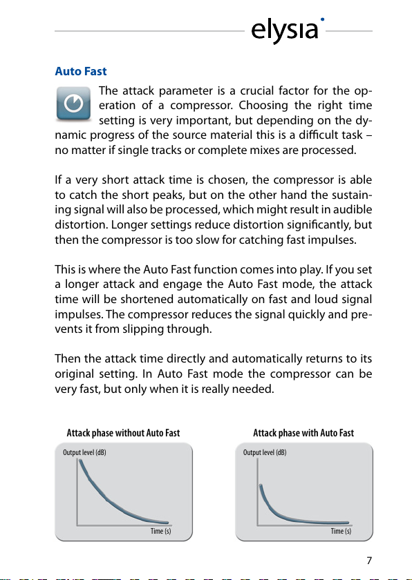
This is where the Auto Fast function comes into play. If you set
a longer attack and engage the Auto Fast mode, the attack
time will be shortened automatically on fast and loud signal
impulses. The compressor reduces the signal quickly and pre-
vents it from slipping through.
Then the attack time directly and automatically returns to its
original setting. In Auto Fast mode the compressor can be
very fast, but only when it is really needed.
Attack phase without Auto Fast Attack phase with Auto Fast
Output level (dB) Output level (dB)
Time (s) Time (s)
7
Page 8

Log Release
It is the time constants and especially the release pa-
rameter that decide if the processing of a compressor
is obvious or unobtrusive to the ear. As it is dicult to
achieve perfect results for all kinds of dierent material with
only one type of release curve, the xpressor 500 oers two dif-
ferent options to choose from: logarithmic and linear.
It is characteristic of a logarithmic release that the time con-
stant shortens when the amount of gain reduction increases.
The advantage of this behavior is that short and loud peaks
(e.g. drums) have a fast release time, while the remaining ma-
terial is processed with a slower release. Its smooth perfor-
mance makes the Log Release especially useful for mastering
and stereo buss compression.
The linear mode, however, has a straight release prole,
without the slower tapering release characteristic of the Log
mode. The linear mode is a good choice for more aggressive
dynamics control of dry signals, and it is especially useful
when you want to process signals which do not have a long
decay period.
Logarithmic release progress Linear release progress
Output level (dB) Output level (dB)
Time (s) Time (s)
8
Page 9

Warm Mode
This function is basically a slew rate limiter that re-
duces the speed of the output amplier stages. This
aects the frequency spectrum, the harmonics and
the transient response at the same time.
Fast transients are slowed down a bit and the overall sound
appears more round and merged. As this function inuences
the behavior of the output stages, the eect it creates has an
impact on the complete processing results of the compressor.
This way the xpressor 500 oers two dierent sound char-
acters at the push of a button: the powerful transparency of
the discrete class-A circuitry and the saturated richness of the
Warm Mode.
Now the choice is really up to you: For transparent compres-
sion and an even frequency response, just use the xpressor
500 in standard mode. For a little bit more fat and juicy sound,
hit the Warm Mode button and you are there!
Added total harmonic distortion Changed frequency response
THD+N (%) Output Level (dB)
Frequency (Hz) Frequency (Hz)
9
Page 10

Negative Ratios
Negative ratios – what exactly does this mean? To
get a better understanding of this function, it makes
sense to realize what the ratio control of a ‘normal’
compressor does:
• 1:1 The signal remains linear, there is no compression pro-
cess going on.
• 1:2 After crossing the threshold, an increase of 2 dB at the
input will be compressed to an increase of 1 dB at the
output.
• 1:∞ After crossing the threshold, the output signal is con-
stantly held at the threshold level without reacting to
further increases at the input (limiter).
At a negative ratio, the characteristic curve bends and returns
back down after crossing the threshold. The louder the input
signal, the lower the output signal – perfect for groovy com-
pression eects.
To get a grip on the extreme ‘destruction’ this can cause, en-
gaging the Gain Reduction Limiter is just the right idea.
Standard compression ratio Negative compression ratio
Input Level (dB) Input Level (dB)
10
Output Level (dB) Output Level (dB)
Page 11

Gain Reduction Limiter
A specialty of the xpressor 500 is the Gain Reduc-
tion Limiter for the control voltage. This limiter is not
placed in the audio path where you would usually
nd it, but in the control path of the compressor instead.
When activated, it limits the control voltage according to the
setting of the GR Limit controller. This means: No matter how
high the input level might become – the amount of gain re-
duction will never exceed the value you have set.
Just think about the GRL as a second threshold controller:
While the ‘regular’ threshold controller tells the compressor
when to start working, the GRL controller tells it when to com-
press no further.
Loud parts in an arrangement can keep their dynamics, as
they will not be compressed beyond the limit of the Gain Re-
duction Limiter.
Note: In the xpressor 500, this function is always active and
does not need a switch of its own.
GRL compression progress GRL input to output ratio
Output Level (dB) Input Level (dB)
Attack phase
Release phase
GRL phase
Time (s) Output Level (dB)
GRL phase
11
Page 12

Technical Details
Frequency response: <10 Hz - 400 kHz (-3.0 dB)
THD+N @ 0 dBu, 20 Hz - 22 kHz, Mix 0 %: 0.002 %
THD+N @ 0 dBu, 20 Hz - 22 kHz, Mix 100 %: 0.006 %
THD+N @ +10 dBu, 20 Hz - 22 kHz, Mix 0 %: 0.003 %
THD+N @ +10 dBu, 20 Hz - 22 kHz, Mix 100 %: 0.056 %
Noise oor, 20 Hz - 20 kHz (A-weighted): -94.0 dBu
Dynamic range, 20 Hz - 22 kHz: 115 dB
Maximum input level: +21 dBu
Maximum output level: +21 dBu
Input impedance: 10 kOhm
Output impedance: 68 Ohm
CE Conformity
elysia GmbH, Am Panneschopp 18, 41334 Nettetal, Ger-
many, declares with sole responsibility that this product
complies with the following norms and directives:
• 2006/95/EG Low Voltage Directive (formerly 73/23/EWG or
93/68/EWG)
• 89/336/EWG EMC (Electromagnetic Compatibility) Directive
• DIN EN 55103-1 EMC of audio equipment - Emission
• DIN EN 55103-2 EMC of audio equipment - Immunity
This declaration becomes invalid by any unapproved modi-
cation of the device.
Nettetal, 01.06.2010 - Ruben Tilgner & Dominik Klaßen
12
Page 13

Precautions
CAUTION: Electricity
• Make sure to operate your API 500 series compatible rack at
the specic mains voltage of your country.
• Replace rack frame fuse with the same type and value only.
• Your rack frame must be connected to ground.
• Do not use a damaged power cord.
• Never place containers with liquid on the rack.
• Do not expose this device to rain or moisture.
• Do not use this device near water.
• Refer service to qualied service sta only.
CAUTION: Temperature
• Surfaces of the device may become hot during operation.
• Do not install this device near any heat source such as radia-
tors, stoves or other heat sources.
CAUTION: Connecting & Mounting
• Never connect to the output of a power amplier.
• Do not apply extensive force when installing this device.
• Use the device according to this manual only.
CAUTION: Humidity
• If this device is moved from a cold place to a warm room,
condensation can occur inside the device. To avoid damag-
ing the unit please allow it to reach room temperature be-
fore switching it on.
13
Page 14

Warranty Info
The xpressor 500 is covered by a limited warranty for a period
of 2 years against defects in parts and labor from the date of
purchase. Natural wear is not covered by this warranty. Re-
pairs or replacements will not extend the warranty period.
The warranty is given to the original purchaser only and is not
transferable. elysia will only give warranty on products pur-
chased through authorized elysia dealers. The warranty will
only be valid in the country of the original purchase unless
otherwise pre-authorized by elysia.
All warranties become void when the product has been dam-
aged by misuse, accident, neglect, modication, tampering or
unauthorized alteration by anyone other than elysia autho-
rized service personnel.
The warrantor assumes no liability for property damage or any
other incidental or consequential damage whatsoever which
may result from failure of this product. Any and all warrantees
of merchantability and tness implied by law are limited to
the duration of the expressed warranty.
elysia will not pay for express or overnight freight service or
pay for shipments to locations outside Germany. All damages
caused by transport are not covered by this warranty.
This warranty gives you specic legal rights and you may also
have other rights which vary from state to state. Some of the
above limitations may not apply to you.
14
Page 15

Legal Info
The information in this document is subject to change with-
out further notice and shall not be deemed as an obligation
or warranty of any kind by the manufacturer. No warranties,
express or implied, are made with regard to the quality, suit-
ability or accuracy of this document.
The manufacturer reserves the right to change the contents
of this document and/or the associated products at any time
without the provision of prior notice. The manufacturer shall
not be held liable for damages of any kind arising from the
use, or the inability to use this product or its documentation.
The information in this document is subject to copyright. All
rights, technical changes and errata are reserved. No part of
this manual may be reproduced or transmitted in any form or
for any purpose without the explicitly written permission of
the copyright holders.
elysia and xpressor are registered trademarks of elysia GmbH.
Other product and brand names contained in this document
are used for identication purposes only. All registered trade-
marks, product designations or brand names used in this doc-
ument are the property of their respective owners.
This product is manufactured according to
the 2002/95/EC directive. The purpose of this
directive of the European Union is the Restric-
tion of Hazardous Substances (RoHS) in electronic equipment
in order to protect health and nature. Dispose separately!
Version 1.2 © 2014 elysia GmbH
15
Page 16

elysia GmbH
Am Panneschopp 18
41334 Nettetal
Germany
info@elysia.com Printed in Germany
 Loading...