

Page 1
Q
E
S
U
M
M
U
S
E
Q
Page 2
The information in this document is subject to
change without further notice and shall not be
deemed as an obligation or warranty of any kind by
the manufacturer. No warranties, express or implied,
are made with regard to the quality, suitability or ac-
curacy of this document.
The manufacturer reserves the right to change the
contents of this document and/or the associated
products at any time without the provision of prior
notice. The manufacturer shall not be held liable for
damages of any kind arising from the use, or the in-
ability to use this product or its documentation.
The information in this document is subject to copy-
right. All rights, technical changes and errata are re-
served. No part of this manual may be reproduced
or transmitted in any form or for any purpose with-
out the explicit written permission of the copyright
holders.
elysia and museq are registered trademarks of elysia
GmbH. Other product and brand names contained
in this document are used for identication purpos-
es only. All registered trademarks, product designa-
tions or brand names used in this document are the
property of their respective owners.
This product is manufactured accord-
ing to the 2002/95/EC directive. The
purpose of this directive of the European Union is
the Restriction of Hazardous Substances (RoHS) in
electronic equipment in order to protect health and
nature. © 2009 elysia GmbH
2
Page 3
WARNING: High Voltage
• Risk of electric shock.
• Do not open chassis.
• Refer service to qualied service sta only.
• Before connecting the device to the main power supply, check if the right
voltage is selected.
• Replace fuse with the same type and value only.
• This device must be connected to ground.
• Do not use a damaged power cord.
• Never place containers with liquid, e.g. beverages or a vase, on the unit.
• Do not expose this device to rain or moisture.
• Do not use this device near water, e.g. swimming pool, bathtub or wet base-
ment.
CAUTION: Temperature
• Surfaces of the device may become hot during operation.
• Do not install this device near any heat source such as radiators, stoves or
other heat sources.
• Always allow enough ventilation space around the unit for air circulation.
• Do not cover circulation vents.
CAUTION: Connecting & Mounting
• Never connect the output of a power amplier to this device.
• Place the unit on a rigid board or place it in an appropriate rack.
• Use the device according to this manual only.
CAUTION: Humidity
• If this device is moved from a cold place to a warm room, condensation can
occur inside the device. To avoid damaging the unit, please allow it to reach
room temperature before switching it on.
CE Conformity
elysia GmbH, Am Panneschopp 18, 41334 Nettetal, Germany, declares with sole
responsibility that this product complies with the following norms and directives:
• 2006/95/EG Low Voltage Directive (formerly 73/23/EWG or 93/68/EWG)
• 89/336/EWG EMC (Electromagnetic Compatibility) Directive
• DIN EN 55103-1 EMC of audio equipment - Emission
• DIN EN 55103-2 EMC of audio equipment - Immunity
This declaration becomes invalid by any unapproved modication of the device.
Nettetal, 01.07.2009 - Ruben Tilgner & Dominik Klaßen
3
Page 4

Dear friend of audio culture,
Only a dream?
A truly musical equalizer which enhances any sound by providing a new dimension of depth,
width, brilliance and openness? Which replaces the tedious search for an adequate change with
nding the right setting intuitively in no time at all? And which oers a truly universal concept,
covering recording, mixing, mastering and creative tasks without cutting back?
You have just woken up. The museq has been designed with exactly these requirements in mind.
You can compliment yourself on your new EQ! A similar combination of exibility and high grade
audio paths without the slightest compromise is rare to nd, and – as far as our experience goes –
the special elysia features like high and low pass lters with additional resonance peak as well as
the integrated warm circuit are unique in the market.
Please take a little time to read this manual thoroughly, as it will help you to entirely understand
the enormous potentials and to really push the envelope. We have paid great attention to practical experience and fast comprehension, which is also the reason for reserving the explanation of
the technological excesses of the museq to our website.
Finally, we would like to thank you sincerely for your condence in our products. If you have further questions or comments, please do not hesitate to contact us – we enjoy being of your service.
But for now, it’s time to wish you lots of fun and musical experiences with your museq.
Use the Force…
the elysians
4
Page 5
BASICS . . . . . . . . . . . . . . . . . . . . . . . . . . . . . . . . . . . . . . . . . . . . . . . . . 6
Controls. . . . . . . . . . . . . . . . . . . . . . . . . . . . . . . . . . . . . . . . . . . . . . . . . . . . . . . 6
Connectors. . . . . . . . . . . . . . . . . . . . . . . . . . . . . . . . . . . . . . . . . . . . . . . . . . . . . 8
Level Issues . . . . . . . . . . . . . . . . . . . . . . . . . . . . . . . . . . . . . . . . . . . . . . . . . . . . 9
Symbols. . . . . . . . . . . . . . . . . . . . . . . . . . . . . . . . . . . . . . . . . . . . . . . . . . . . . . . 9
REFERENCE . . . . . . . . . . . . . . . . . . . . . . . . . . . . . . . . . . . . . . . . . . . . . .10
Low Shelf . . . . . . . . . . . . . . . . . . . . . . . . . . . . . . . . . . . . . . . . . . . . . . . . . . . . . .10
High Shelf . . . . . . . . . . . . . . . . . . . . . . . . . . . . . . . . . . . . . . . . . . . . . . . . . . . . .10
Low Cut. . . . . . . . . . . . . . . . . . . . . . . . . . . . . . . . . . . . . . . . . . . . . . . . . . . . . . .11
High Cut . . . . . . . . . . . . . . . . . . . . . . . . . . . . . . . . . . . . . . . . . . . . . . . . . . . . . .11
Bottom . . . . . . . . . . . . . . . . . . . . . . . . . . . . . . . . . . . . . . . . . . . . . . . . . . . . . . .11
Middle. . . . . . . . . . . . . . . . . . . . . . . . . . . . . . . . . . . . . . . . . . . . . . . . . . . . . . . .12
Top . . . . . . . . . . . . . . . . . . . . . . . . . . . . . . . . . . . . . . . . . . . . . . . . . . . . . . . . . .12
Warm . . . . . . . . . . . . . . . . . . . . . . . . . . . . . . . . . . . . . . . . . . . . . . . . . . . . . . . .13
Harmonics . . . . . . . . . . . . . . . . . . . . . . . . . . . . . . . . . . . . . . . . . . . . . . . . . . . . .13
APPENDIX . . . . . . . . . . . . . . . . . . . . . . . . . . . . . . . . . . . . . . . . . . . . . . .14
Technical Data. . . . . . . . . . . . . . . . . . . . . . . . . . . . . . . . . . . . . . . . . . . . . . . . . . .14
Warranty . . . . . . . . . . . . . . . . . . . . . . . . . . . . . . . . . . . . . . . . . . . . . . . . . . . . . .15
Recall Sheet . . . . . . . . . . . . . . . . . . . . . . . . . . . . . . . . . . . . . . . . . . . . . . . . . . . .16
Left Audio
Input
Input
Stage
Input
Stage
Right Audio
Input
Shelf/Cut
Type
Low
Band
Boost/Cut
Mode
Boost/Cut
Mode
Low
Band
Shelf/Cut
Type
Wide/Narrow
Q
Bottom
Band
Boost/Cut
Mode
Boost/Cut
Mode
Bottom
Band
Wide/Narrow
Q
Wide/Narrow
Q
Middle
Band
Boost/Cut
Mode
Boost/Cut
Mode
Middle
Band
Wide/Narrow
Q
Wide/Narrow
Q
Top
Band
Boost/Cut
Mode
Boost/Cut
Mode
Top
Band
Wide/Narrow
Q
Shelf/Cut
Type
High
Band
Boost/Cut
Mode
Boost/Cut
Mode
High
Band
Shelf/Cut
Type
Left Audio
Output
Output
Stage
Warm
Mode
Warm
Mode
Output
Stage
Right Audio
Output
INDEX
5
Page 6
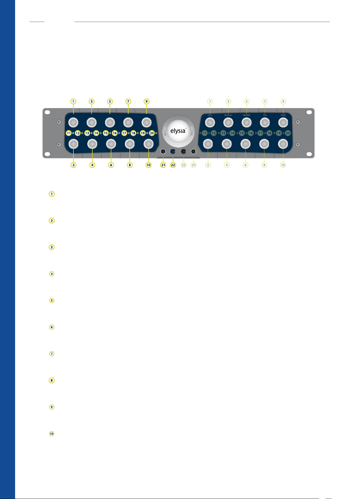
Low Bottom HighTopMiddle
BASICS
Controls
Both channels of the museq are absolutely identical regarding their electronic design. Therefore
both sides of the front panel have exactly the same controls and switches. Every potentiometer
oers 23 steps for a comfortable recall with an ample choice of values.
Low Bottom HighTopMiddle
Left Warm Warm Right
Gain (Low Band): boosts frequencies in the Low Band up to 15 dB or – if the Cut Gain switch
is activated – cuts them up to 15 dB. In Low Cut mode: sets the amount of resonance. (p. 10)
Frequency (Low Band): determines the frequency of the Low Shelf/Low Cut lter. The frequency range of this band lies between 9 and 200 Hz. (p. 10)
Gain (Bottom Band): boosts frequencies in the Bottom Band up to 15 dB or – if the Cut Gain
switch is activated – cuts them up to 15 dB. (p. 11)
Frequency (Bottom Band): determines the frequency of this parametric peak lter. The frequency range of this band lies between 18 and 400 Hz. (p. 11)
Gain (Middle Band): boosts frequencies in the Middle Band up to 15 dB or – if the Cut Gain
switch is activated – cuts them up to 15 dB. (p. 12)
Frequency (Middle Band): determines the frequency of this parametric peak lter. The frequency range of this band lies between 150 and 3.5 kHz. (p. 12)
Gain (Top Band): boosts frequencies in the Top Band up to 15 dB or – if the Cut Gain switch
is activated – cuts them up to 15 dB. (p. 12)
BASICS – Controls
6
Frequency (Top Band): determines the frequency of this parametric peak lter. The frequen-
cy range of this band lies between 700 and 16 kHz. (p. 12)
Gain (High Band): boosts frequencies in the High Band up to 15 dB or – if the Cut Gain switch
is activated – cuts them up to 15 dB. In High Cut mode: sets the amount of resonance. (p. 10)
Frequency (High Band): determines the frequency of the High Shelf/High Cut lter. The frequency range of this band lies between 1.8 and 35 kHz. (p. 10)
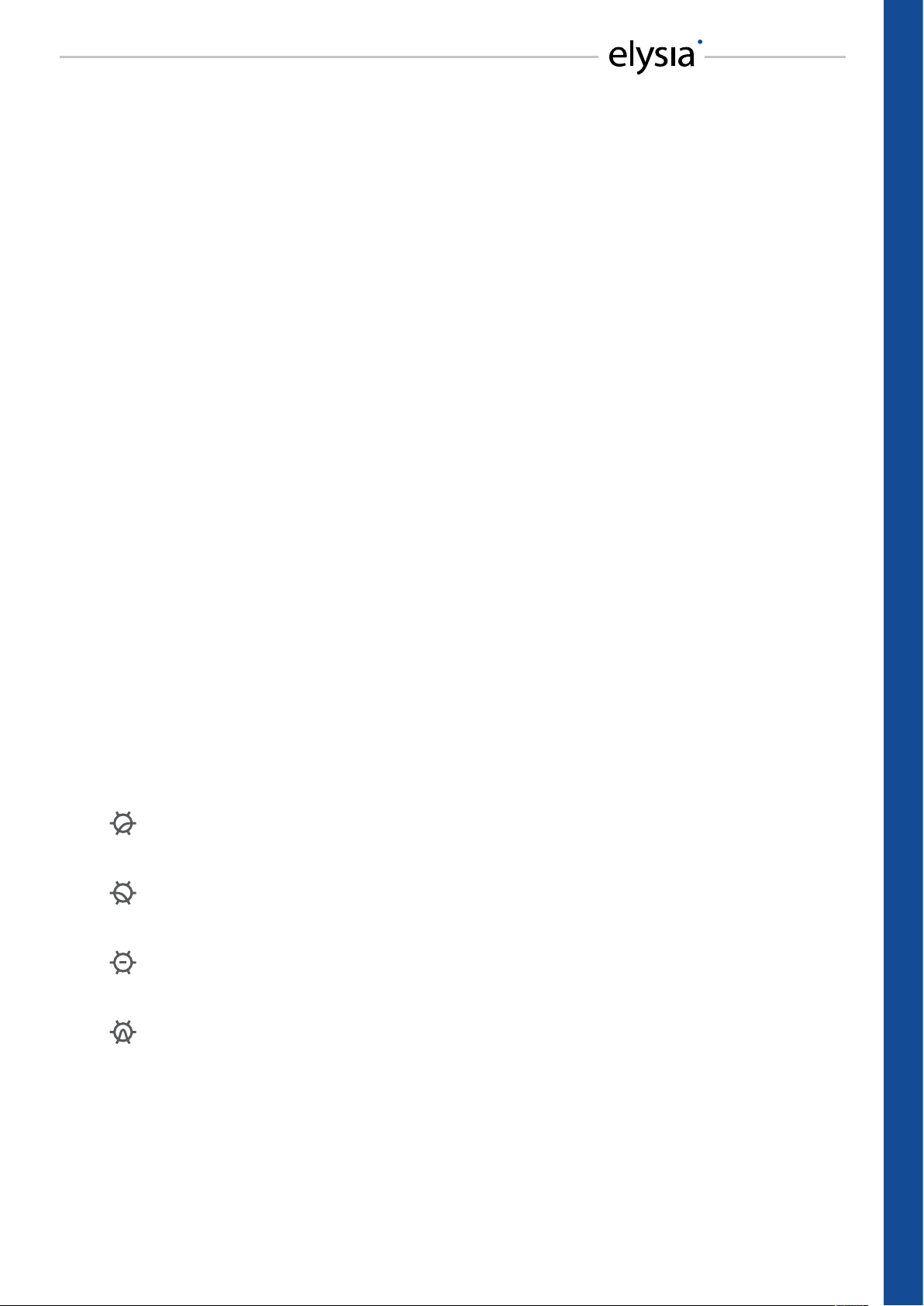
Page 7

Low Cut (Low Band): switches the lter characteristics from Low Shelf to Low Cut with additional resonance peak (p. 11)
Cut Gain (Low Band): switches the corresponding gain controller from boost to cut mode.
This is only relevant for Low Shelf, but not for Low Cut mode. (p. 10)
Narrow Q (Bottom Band): switches the quality factor (Q) of the corresponding frequency
band from low (wide curve) to high (narrow curve). (p. 11)
Cut Gain (Bottom Band): switches the corresponding gain controller from boost to cut
mode. (p. 11)
Narrow Q (Middle Band): switches the quality factor (Q) of the corresponding frequency
band from low (wide curve) to high (narrow curve). (p. 12)
Cut Gain (Middle Band): switches the corresponding gain controller from boost to cut mode.
(p. 12)
Narrow Q (Top Band): switches the quality factor (Q) of the corresponding frequency band
from low (wide curve) to high (narrow curve). (p. 12)
Cut Gain (Top Band): switches the corresponding gain controller from boost to cut mode.
(p. 12)
High Cut (High Band): switches the lter characteristics from High Shelf to High Cut with
additional resonance peak (p. 11)
Cut Gain (High Band): switches the corresponding gain controller from boost to cut mode.
This is only relevant for High Shelf, but not for High Cut mode. (p. 10)
Left/Right: activates the respective channel of the equalizer. In deactivated state, the input
is directly routed to the output by a hardwire bypass.
Warm: reduces the slew rate of the output amplier stages. Adds harmonics and produces a
vintage-like warm sound. (p. 13)
BASICS – Controls
7
Page 8

BASICS
Connectors
Please pay attention to operate the museq with the correct voltage setting for your country and
the proper pin assignments on the XLR connectors.
Made in Germany
WARNING!
DO NOT OPEN - RISK OF ELECTRIC SHOCK!
elysia GmbH • D-41334 Nettetal • Germany
Power Consumption 60 W
Voltage
220 - 240 VAC
~ 50 Hz
110 - 120 VAC
~ 60 Hz
Fuse Type
0.8 A Slo-Blo
@ 220 - 240 VAC
1.5 A Slo-Blo
@ 110 - 120 VAC
Gnd
3
(Idle)
3
Right Output
2 Hot Gnd 1
2 Hot Gnd 1
- Balanced -
- Unbalanced -
Cold
3
Gnd
3
Right Input
Gnd
3
1 Gnd Hot 2
1 Gnd Hot 2
(Idle)
3
Left Output
2 Hot Gnd 1
2 Hot Gnd 1
- Balanced -
- Unbalanced -
Cold
Gnd
Left Input
3
1 Gnd Hot 2
3
1 Gnd Hot 2
Mains module
This module combines the line cord connector, the on/o switch, the fuse holder with integrated 230/115 VAC voltage selector and a line lter for providing the transformer with
clean current.
WARNING: High voltage
Make sure to disconnect the line cord before replacing eventually blown fuses or changing
the operating voltage of the unit! In order to change the operating voltage, the fuse holder
has to be taken out and re-inserted so that the desired voltage can be read correctly (and is
not standing upside down). Note: Some export versions have a xed voltage of e.g. 100 or
115 VAC and cannot operate at 230 VAC.
WARNING: Fuses
Always make sure to use the correct fuses for the chosen voltage: 230 VAC 0.8 A Slo-Blo or
115 VAC 1.6 A Slo-Blo. Incorrect or missing fuses are dangerous safety hazards for both the
unit and yourself!
Brightness trimmer
You can use a small screwdriver to adjust the light intensity of the front panel logo disc.
Audio outputs (+4 dBu)
Pin assignment balanced: 1 ground 2 hot (+) 3 ground
Pin assignment unbalanced: 1 ground 2 hot (+) 3 idle
Audio inputs (+4 dBu)
Pin assignment balanced: 1 ground 2 hot (+) 3 cold (-)
Pin assignment unbalanced: 1 ground 2 hot (+) 3 ground
Note: If a device that is placed in the signal chain before the museq has an unbalanced
output stage, a complete mute can eventually occur when the equalizer is activated. If this
happens, please follow the advice on the next page.
BASICS – Connectors
8
Page 9
Level Issues
Low Level
This problem can eventually be caused by balanced wiring. If the level becomes low when the
museq is activated, a pin of the XLR connector at the input is probably not connected. To ensure
proper operation, make sure to have both pins connected.
The classic example for this problem is a balanced XLR cable that is connected to an unbalanced
output which only uses ground and pin 2 – connecting pin 3 to ground should solve the trouble.
Level Jump
In some audio processors the output stage is designed in a way that the level will always stay the
same – no matter if it is connected with a balanced or an unbalanced cable. If pin 3 is connected
to ground, for example, the level at pin 2 will automatically become twice as loud as before. This
kind of output stage is usually unproblematic.
But there are also stages which cannot compensate that. Then the level at pin 2 stays as it is, even
if pin 3 is connected to ground. If the museq is placed between a device with this kind of output
stage and a device with unbalanced inputs with pin 3 connected to ground, it is possible that the
level will jump up by 6 dB when the equalizer is activated.
As a general rule, balanced input stages are always the best choice. In case they are not available,
the rst attempt to solve this problem should be to disconnect pin 3 at the XLR inputs of the
museq and then connect it to ground. This generates an unbalanced signal that should not shift
levels anymore.
Symbols
In order to maintain a clearly arranged front panel, the museq uses the following symbols:
Low Cut
LED on: lter is in Low Cut mode | LED o: lter is in Low Shelf mode
High Cut
LED on: lter is in High Cut mode | LED o: lter is in High Shelf mode
Cut Gain
LED on: frequency band is attenuated | LED o: frequency band is boosted
Narrow Q
LED on: high quality factor (Q) | LED o: low quality factor (Q)
BASICS – Level Issues & Symbols
9
Page 10

Warm
Warm
Hz
185
230
320
18
20
35
60
400
25
150
110
130
Hz
1k5
2k0
2k7
150
170
300
520
3k5
210
1k3
770
1k1
Hz
17k
22k
30k
1k8
2k0
3k5
5k7
35k
2k5
10k
12k
14k
Hz
7k1
9k3
13k
700
780
1k7
2k5
16k
1k0
3k7
4k9
5k8
dB
High
9.0
11
13
0
1.0
4.0
5.0
15
2.5
6.0
7.0
dB
Top
11
13
14
0
0.5
3.5
4.5
15
2.0
5.5
6.5
dB
Middle
11
13
14
0
0.5
3.5
4.5
15
2.0
5.5
6.5
dB
Bottom
11
13
14
0
0.5
3.5
4.5
15
2.0
5.5
6.5
dB
High
9.0
11
13
0
1.0
4.0
5.0
15
2.5
6.0
7.0
dB
Top
11
13
14
0
0.5
3.5
4.5
15
2.0
5.5
6.5
dB
Middle
11
13
14
0
0.5
3.5
4.5
15
2.0
5.5
6.5
dB
Bottom
11
13
14
0
0.5
3.5
4.5
15
2.0
5.5
6.5
Hz
185
230
320
18
20
35
60
400
25
150
110
130
Hz
1k5
2k0
2k7
150
170
300
520
3k5
210
1k3
770
1k1
Hz
17k
22k
30k
1k8
2k0
3k5
5k7
35k
2k5
10k
12k
14k
Hz
7k1
9k3
13k
700
780
1k7
2k5
16k
1k0
3k7
4k9
5k8
Warm
Warm
Hz
185
230
320
18
20
35
60
400
25
150
110
130
Hz
1k5
2k0
2k7
150
170
300
520
3k5
210
1k3
770
1k1
Hz
95
120
160
9
10
18
30
200
12
55
65
75
Hz
7k1
9k3
13k
700
780
1k7
2k5
16k
1k0
3k7
4k9
5k8
dB
Low
9.0
11
13
0
1.0
4.0
5.0
15
2.5
6.0
7.0
dB
Top
11
13
14
0
0.5
3.5
4.5
15
2.0
5.5
6.5
dB
Middle
11
13
14
0
0.5
3.5
4.5
15
2.0
5.5
6.5
dB
Bottom
11
13
14
0
0.5
3.5
4.5
15
2.0
5.5
6.5
dB
Low
9.0
11
13
0
1.0
4.0
5.0
15
2.5
6.0
7.0
dB
Top
11
13
14
0
0.5
3.5
4.5
15
2.0
5.5
6.5
dB
Middle
11
13
14
0
0.5
3.5
4.5
15
2.0
5.5
6.5
dB
Bottom
11
13
14
0
0.5
3.5
4.5
15
2.0
5.5
6.5
Hz
185
230
320
18
20
35
60
400
25
150
110
130
Hz
1k5
2k0
2k7
150
170
300
520
3k5
210
1k3
770
1k1
Hz
95
120
160
9
10
18
30
200
12
55
65
75
Hz
7k1
9k3
13k
700
780
1k7
2k5
16k
1k0
3k7
4k9
5k8
REFERENCE
7.0
6.0
Low
5.0
9.0
4.0
11
2.5
1.0
13
15
0
dB
65
55
30
75
95
18
120
12
10
160
200
9
Hz
Left
Right
7.0
6.0
Low
5.0
9.0
4.0
11
2.5
1.0
13
15
0
dB
65
55
30
75
95
18
120
12
10
160
200
9
Hz
Low Shelf
Left: miscellaneous settings of the gain controller in boost (red) and cut mode (green)
Right: miscellaneous settings of the frequency controller in boost mode
Low Shelf Gain
dBr
A
dBr
A
Low Shelf Frequency
20 50 100 200 500 1k 2k 5k 10k 50k 100k Hz10
7.0
6.0
High
5.0
9.0
4.0
11
2.5
1.0
13
15
0
dB
12k
10k
5k7
14k
17k
3k5
22k
2k5
2k0
30k
35k
1k8
Hz
Left
20 50 100 200 500 1k 2k 5k 10k 50k 100k Hz10
Right
High Shelf
Left: miscellaneous settings of the gain controller in boost (red) and cut mode (green)
Right: miscellaneous settings of the frequency controller in boost mode
High Shelf Gain
High Shelf Frequency
7.0
6.0
High
5.0
9.0
4.0
11
2.5
1.0
13
15
0
dB
12k
10k
5k7
14k
17k
3k5
22k
2k5
2k0
30k
35k
1k8
Hz
dBr
A
20 50 100 200 500 1k 2k 5k 10k 50k 100k Hz10
dBr
A
20 50 100 200 500 1k 2k 5k 10k 50k 100k Hz10
REFERENCE – Low Shelf & High Shelf
10
Page 11

Warm
Warm
Hz
185
230
320
18
20
35
60
400
25
150
110
130
Hz
1k5
2k0
2k7
150
170
300
520
3k5
210
1k3
770
1k1
Hz
7k1
9k3
13k
700
780
1k7
2k5
16k
1k0
3k7
4k9
5k8
7.0
dB
Top
11
13
14
0
0.5
3.5
4.5
15
2.0
5.5
6.5
dB
Middle
11
13
14
0
0.5
3.5
4.5
15
2.0
5.5
6.5
dB
Bottom
11
13
14
0
0.5
3.5
4.5
15
2.0
5.5
6.5
dB
Top
11
13
14
0
0.5
3.5
4.5
15
2.0
5.5
6.5
dB
Middle
11
13
14
0
0.5
3.5
4.5
15
2.0
5.5
6.5
dB
Bottom
11
13
14
0
0.5
3.5
4.5
15
2.0
5.5
6.5
Hz
185
230
320
18
20
35
60
400
25
150
110
130
Hz
1k5
2k0
2k7
150
170
300
520
3k5
210
1k3
770
1k1
Hz
7k1
9k3
13k
700
780
1k7
2k5
16k
1k0
3k7
4k9
5k8
Warm
Warm
Hz
1k5
2k0
2k7
150
170
300
520
3k5
210
1k3
770
1k1
Hz
95
120
160
9
10
18
30
200
12
55
65
75
Hz
17k
22k
30k
1k8
2k0
3k5
5k7
35k
2k5
10k
12k
14k
Hz
7k1
9k3
13k
700
780
1k7
2k5
16k
1k0
3k7
4k9
5k8
dB
High
9.0
11
13
0
1.0
4.0
5.0
15
2.5
6.0
7.0
dB
Low
9.0
11
13
0
1.0
4.0
5.0
15
2.5
6.0
7.0
dB
Top
11
13
14
0
0.5
3.5
4.5
15
2.0
5.5
6.5
dB
Middle
11
13
14
0
0.5
3.5
4.5
15
2.0
5.5
6.5
dB
High
9.0
11
13
0
1.0
4.0
5.0
15
2.5
6.0
7.0
dB
Low
9.0
11
13
0
1.0
4.0
5.0
15
2.5
6.0
7.0
dB
Top
11
13
14
0
0.5
3.5
4.5
15
2.0
5.5
6.5
dB
Middle
11
13
14
0
0.5
3.5
4.5
15
2.0
5.5
6.5
Hz
1k5
2k0
2k7
150
170
300
520
3k5
210
1k3
770
1k1
Hz
95
120
160
9
10
18
30
200
12
55
65
75
Hz
17k
22k
30k
1k8
2k0
3k5
5k7
35k
2k5
10k
12k
14k
Hz
7k1
9k3
13k
700
780
1k7
2k5
16k
1k0
3k7
4k9
5k8
6.0
Low
5.0
9.0
4.0
11
2.5
1.0
13
15
0
dB
65
55
30
75
95
18
120
12
10
160
200
9
Hz
7.0
6.0
High
5.0
9.0
4.0
11
2.5
1.0
13
15
0
dB
12k
10k
5k7
14k
17k
3k5
22k
2k5
2k0
30k
35k
1k8
Hz
Left
Right
7.0
6.0
Low
5.0
9.0
4.0
11
2.5
1.0
13
15
0
dB
65
55
30
75
95
18
120
12
10
160
200
9
Hz
7.0
6.0
High
5.0
4.0
2.5
1.0
13
15
0
dB
12k
10k
5k7
14k
3k5
2k5
2k0
30k
35k
1k8
Hz
Low Cut/High Cut
Left: miscellaneous settings of the gain controller at the same frequency in low cut mode
Right: miscellaneous settings of the gain controller at the same frequency in high cut mode
9.0
11
17k
22k
Low Cut Gain
dBr
A
20 50 100 200 500 1k 2k 5k 10k Hz10
6.5
5.5
Bottom
4.5
11
3.5
13
2.0
0.5
14
15
0
dB
110
130
60
150
185
35
230
25
20
320
400
18
Hz
Left
dBr
A
50 100 200 500 1k 2k 5k 10k Hz
4.5
3.5
2.0
0.5
60
35
25
20
Right
18
High Cut Gain
20k 50k 100k
6.5
5.5
Bottom
11
13
14
15
0
dB
130
110
150
185
230
320
400
Hz
Bottom
Left: miscellaneous settings of the gain controller with wide (green) and narrow Q (red)
Right: miscellaneous settings of the frequency controller in boost mode with wide Q
Bottom Gain
dBr
A
20 50 100 200 500 1k 2k 5k 10k 50k 100k Hz10
dBr
A
20 50 100 200 500 1k 2k 5k 10k 50k 100k Hz10
Bottom Frequency
REFERENCE – Low Cut/High Cut & Bottom
11
Page 12

Warm
Warm
Hz
185
230
320
18
20
35
60
400
25
150
110
130
Hz
95
120
160
9
10
18
30
200
12
55
65
75
Hz
17k
22k
30k
1k8
2k0
3k5
5k7
35k
2k5
10k
12k
14k
Hz
7k1
9k3
13k
700
780
1k7
2k5
16k
1k0
3k7
4k9
5k8
dB
High
9.0
11
13
0
1.0
4.0
5.0
15
2.5
6.0
7.0
dB
Low
9.0
11
13
0
1.0
4.0
5.0
15
2.5
6.0
7.0
dB
Top
11
13
14
0
0.5
3.5
4.5
15
2.0
5.5
6.5
dB
Bottom
11
13
14
0
0.5
3.5
4.5
15
2.0
5.5
6.5
dB
High
9.0
11
13
0
1.0
4.0
5.0
15
2.5
6.0
7.0
dB
Low
9.0
11
13
0
1.0
4.0
5.0
15
2.5
6.0
7.0
dB
Top
11
13
14
0
0.5
3.5
4.5
15
2.0
5.5
6.5
dB
Bottom
11
13
14
0
0.5
3.5
4.5
15
2.0
5.5
6.5
Hz
185
230
320
18
20
35
60
400
25
150
110
130
Hz
95
120
160
9
10
18
30
200
12
55
65
75
Hz
17k
22k
30k
1k8
2k0
3k5
5k7
35k
2k5
10k
12k
14k
Hz
7k1
9k3
13k
700
780
1k7
2k5
16k
1k0
3k7
4k9
5k8
Warm
Warm
Hz
185
230
320
18
20
35
60
400
25
150
110
130
Hz
1k5
2k0
2k7
150
170
300
520
3k5
210
1k3
770
1k1
Hz
95
120
160
9
10
18
30
200
12
55
65
75
Hz
17k
22k
30k
1k8
2k0
3k5
5k7
35k
2k5
10k
12k
14k
dB
High
9.0
11
13
0
1.0
4.0
5.0
15
2.5
6.0
7.0
dB
Low
9.0
11
13
0
1.0
4.0
5.0
15
2.5
6.0
7.0
dB
Middle
11
13
14
0
0.5
3.5
4.5
15
2.0
5.5
6.5
dB
Bottom
11
13
14
0
0.5
3.5
4.5
15
2.0
5.5
6.5
dB
High
9.0
11
13
0
1.0
4.0
5.0
15
2.5
6.0
7.0
dB
Low
9.0
11
13
0
1.0
4.0
5.0
15
2.5
6.0
7.0
dB
Middle
11
13
14
0
0.5
3.5
4.5
15
2.0
5.5
6.5
dB
Bottom
11
13
14
0
0.5
3.5
4.5
15
2.0
5.5
6.5
Hz
185
230
320
18
20
35
60
400
25
150
110
130
Hz
1k5
2k0
2k7
150
170
300
520
3k5
210
1k3
770
1k1
Hz
95
120
160
9
10
18
30
200
12
55
65
75
Hz
17k
22k
30k
1k8
2k0
3k5
5k7
35k
2k5
10k
12k
14k
REFERENCE
6.5
5.5
Middle
4.5
11
3.5
13
2.0
0.5
14
15
0
dB
770
1k1
520
1k3
1k5
300
2k0
210
170
2k7
3k5
150
Hz
Left
Right
6.5
5.5
Middle
4.5
3.5
2.0
0.5
15
0
dB
1k1
770
520
1k3
1k5
300
210
170
2k7
3k5
150
Hz
Middle
Left: miscellaneous settings of the gain controller with wide (green) and narrow Q (red)
Right: miscellaneous settings of the frequency controller in boost mode with wide Q
Middle Gain
dBr
A
dBr
A
Middle Frequency
11
13
14
2k0
20 50 100 200 500 1k 2k 5k 10k 50k 100k Hz10
6.5
5.5
Top
4.5
11
3.5
13
2.0
0.5
14
15
0
dB
4k9
3k7
2k5
5k8
7k1
1k7
9k3
1k0
780
13k
16k
700
Hz
Left
20 50 100 200 500 1k 2k 5k 10k 50k 100k Hz10
6.5
5.5
Top
4.5
11
3.5
13
2.0
0.5
14
15
0
dB
4k9
3k7
2k5
5k8
7k1
1k7
9k3
1k0
780
13k
16k
700
Right
Hz
Top
Left: miscellaneous settings of the gain controller with wide (green) and narrow Q (red)
Right: miscellaneous settings of the frequency controller in boost mode with wide Q
Top Gain
Top Frequency
dBr
A
20 50 100 200 500 1k 2k 5k 10k 50k 100k Hz10
dBr
A
20 50 100 200 500 1k 2k 5k 10k 50k 100k Hz10
REFERENCE – Middle & Top
12
Page 13

Left Warm Warm Right
Hz
185
230
320
18
20
35
60
400
25
150
110
130
Hz
1k5
2k0
2k7
150
170
300
520
3k5
210
1k3
770
1k1
Hz
95
120
160
9
10
18
30
200
12
55
65
75
Hz
17k
22k
30k
1k8
2k0
3k5
5k7
35k
2k5
10k
12k
14k
Hz
7k1
9k3
13k
700
780
1k7
2k5
16k
1k0
3k7
4k9
5k8
dB
High
9.0
11
13
0
1.0
4.0
5.0
15
2.5
6.0
7.0
dB
Low
9.0
11
13
0
1.0
4.0
5.0
15
2.5
6.0
7.0
dB
Top
11
13
14
0
0.5
3.5
4.5
15
2.0
5.5
6.5
dB
Middle
11
13
14
0
0.5
3.5
4.5
15
2.0
5.5
6.5
dB
Bottom
11
13
14
0
0.5
3.5
4.5
15
2.0
5.5
6.5
dB
High
9.0
11
13
0
1.0
4.0
5.0
15
2.5
6.0
7.0
dB
Low
9.0
11
13
0
1.0
4.0
5.0
15
2.5
6.0
7.0
dB
Top
11
13
14
0
0.5
3.5
4.5
15
2.0
5.5
6.5
dB
Middle
11
13
14
0
0.5
3.5
4.5
15
2.0
5.5
6.5
dB
Bottom
11
13
14
0
0.5
3.5
4.5
15
2.0
5.5
6.5
Hz
185
230
320
18
20
35
60
400
25
150
110
130
Hz
1k5
2k0
2k7
150
170
300
520
3k5
210
1k3
770
1k1
Hz
95
120
160
9
10
18
30
200
12
55
65
75
Hz
17k
22k
30k
1k8
2k0
3k5
5k7
35k
2k5
10k
12k
14k
Hz
7k1
9k3
13k
700
780
1k7
2k5
16k
1k0
3k7
4k9
5k8
Warm
Warm
Hz
185
230
320
18
20
35
60
400
25
150
110
130
Hz
1k5
2k0
2k7
150
170
300
520
3k5
210
1k3
770
1k1
Hz
95
120
160
9
10
18
30
200
12
55
65
75
Hz
17k
22k
30k
1k8
2k0
3k5
5k7
35k
2k5
10k
12k
14k
Hz
7k1
9k3
13k
700
780
1k7
2k5
16k
1k0
3k7
4k9
5k8
dB
High
9.0
11
13
0
1.0
4.0
5.0
15
2.5
6.0
7.0
dB
Low
9.0
11
13
0
1.0
4.0
5.0
15
2.5
6.0
7.0
dB
Top
11
13
14
0
0.5
3.5
4.5
15
2.0
5.5
6.5
dB
Middle
11
13
14
0
0.5
3.5
4.5
15
2.0
5.5
6.5
dB
Bottom
11
13
14
0
0.5
3.5
4.5
15
2.0
5.5
6.5
dB
High
9.0
11
13
0
1.0
4.0
5.0
15
2.5
6.0
7.0
dB
Low
9.0
11
13
0
1.0
4.0
5.0
15
2.5
6.0
7.0
dB
Top
11
13
14
0
0.5
3.5
4.5
15
2.0
5.5
6.5
dB
Middle
11
13
14
0
0.5
3.5
4.5
15
2.0
5.5
6.5
dB
Bottom
11
13
14
0
0.5
3.5
4.5
15
2.0
5.5
6.5
Hz
185
230
320
18
20
35
60
400
25
150
110
130
Hz
1k5
2k0
2k7
150
170
300
520
3k5
210
1k3
770
1k1
Hz
95
120
160
9
10
18
30
200
12
55
65
75
Hz
17k
22k
30k
1k8
2k0
3k5
5k7
35k
2k5
10k
12k
14k
Hz
7k1
9k3
13k
700
780
1k7
2k5
16k
1k0
3k7
4k9
5k8
Warm
Left: distortion rate in % at dierent input levels in Warm mode
Right: frequency response at dierent input levels in Warm mode
Warm THD+N
%
20 50 100 200 500 1k 2k 5k 10k 50k Hz
20k
Warm Frequency Response
dBr
A
20 50 100 200 500 1k 2k 5k 10k 50k 100k Hz
Left
Right
20k
Harmonics
Left: harmonic spectrum on 0 dBu @ 1 kHz
Right: harmonic spectrum on 10 dBu @ 1 kHz
FFT @ 0 dBu
dBu
20 50 100 200 500 1k 2k 5k 10k 20k Hz
dBu
20 50 100 200 500 1k 2k 5k 10k 20k Hz
FFT @ 10 dBu
REFERENCE – Warm & Harmonics
13
Page 14

APPENDIX
Technical Data
Frequency response: <10 Hz - >200 kHz (-0.2 dB)
Low Band (Shelf Filter): 9 - 200 Hz (+/-15 dB)
Low Band (Cut Filter): 9 - 200 Hz
Bottom Band (Peak Filter): 18 - 400 Hz (+/-15 dB)
Quality factor (Q): 1.3 (wide) and 0.5 (narrow)
Middle Band (Peak Filter): 150 Hz - 3.5 kHz (+/-15 dB)
Quality factor (Q): 1.3 (wide) and 0.5 (narrow)
Top Band (Peak Filter): 700 Hz - 16 kHz (+/-15 dB)
Quality factor (Q): 1.3 (wide) and 0.5 (narrow)
High Band (Shelf Filter): 1.8 - 35 kHz (+/-15 dB)
High Band (Cut Filter): 1.8 - 35 kHz
THD+N @ 0 dBu, 20 Hz - 22 kHz: 0.0037 %
THD+N @ +10 dBu, 20 Hz - 22 kHz: 0.0038 %
Noise oor, 20 Hz - 20 kHz (A-weighted): -91.6 dBu
Dynamic range, 20 Hz - 22 kHz: 119 dB
Maximum input level: +27 dBu
Maximum output level: +27 dBu
Input impedance: 10 kOhm
Output impedance: 68 Ohm
Input pin assignment: 1. Ground
2. Positive
3. Negative
Output pin assignment: 1. Ground
2. Positive
3. With 68 Ohm to Ground
Power consumption: 60 W max
Fuse type: 230 VAC 0.8 A Slo-Blo
115 VAC 1.6 A Slo-Blo
Dimensions (W x H x D): 483 mm x 89 mm x 377 mm
19 “ x 3.5“ (2 U) x 14.8“
14
Weight: 8 kg / 18 lb
APPENDIX – Technical Data
Page 15

Warranty
Conditions and limitations
The museq is covered by a limited warranty for a period of 24 month against defects in parts and labor from
the date of purchase. Natural wear is not covered by this warranty. elysia will remedy problems caused by
material or workmanship either by repair or replacement to restore the product to full performance without
charge for parts and labor. Repairs or replacements will not extend the warranty period.
The warranty is given to the original purchaser only and is not transferable. elysia will only give warranty on
products purchased through authorized elysia dealers. The warranty will only be valid in the country of the
original purchase unless otherwise pre-authorized by elysia.
All warranties become void when the product has been damaged by misuse, accident, neglect, modication, tampering or unauthorized alteration by anyone other than elysia authorized service personnel.
The warrantor assumes no liability for property damage or any other incidental or consequential damage
whatsoever which may result from failure of this product. Any and all warrantees of merchantability and tness implied by law are limited to the duration of the expressed warranty.
This warranty gives you specic legal rights and you may also have other rights which vary from state to
state. Some of the above limitations may not apply to you.
Return and packaging
In case you notice any defect, please contact elysia directly for technical support. You can nd the correspondent contact data at the end of this warranty statement. You will receive a return authorization which
enables you to send your product to the elysia factory where it will be repaired and then sent back to you.
All returns to the factory must be in the original packaging, accompanied by the return authorization, and
must be shipped via insured freight at the customer‘s own expense. A new original packaging can be ordered from elysia. The customer may be charged for new factory original packaging if he fails to ship the
product in the original factory packaging.
In case that a product must be returned to the factory from a country outside Germany, the customer shall
adhere to specic shipping, customs, and commercial invoicing instructions given with the return authorization as elysia will not be responsible for transportation costs or customs fees related to any importation or
re-exportation charges whatsoever.
After repair, the product will be returned to the customer via prepaid, insured freight, method and carrier to
be determined by elysia. elysia will not pay for express or overnight freight service or pay for shipments to
locations outside Germany. All damages caused by transport are not covered by this warranty.
Contact data
For technical support please contact:
elysia GmbH
Am Panneschopp 18
41334 Nettetal
Germany
info@elysia.com
Version 1.1
Printed in Germany
15
APPENDIX – Warranty
Page 16

7.0
6.0
6.5
5.5
6.5
5.5
6.5
5.5
7.0
6.0
5.0
4.5
Middle
4.5
4.5
Low Bottom Top High
5.0
11
9.0
13
15
0
1.0
4.0
2.5
13
11
14
15
dB dB
0
0.5
3.5
2.0
13
11
14
15
0
0.5
3.5
2.0
13
11
14
15
0
0.5
3.5
2.0
11
9.0
13
15
dB dB dB
0
1.0
4.0
2.5
22k
17k
30k
14k
12k
10k
5k7
5k8
4k9
3k7
2k5
1k3
1k1
770
520
150
130
110
60
75
65
55
30
35k
Hz
1k8
2k0
3k5
2k5
9k3
7k1
13k
16k
Hz
700
780
1k7
1k0
2k0
1k5
2k7
3k5
Hz
150
170
300
210
230
185
320
400
18
20
35
25
120
95
160
200
Hz Hz
9
10
18
12
7.0
6.0
6.5
5.5
6.5
5.5
6.5
5.5
7.0
6.0
5.0
4.5
Middle
4.5
4.5
Low Bottom Top High
5.0
Left Warm Warm Right
22k
17k
11
9.0
13
12k
15
10k
0
1.0
4.0
2.5
13
11
14
15
4k9
dB dB
3k7
0
0.5
3.5
2.0
13
11
14
15
1k1
770
0
0.5
3.5
2.0
13
11
14
15
130
110
0
0.5
3.5
2.0
11
9.0
13
15
65
dB dB dB
55
0
1.0
4.0
2.5
30k
14k
5k7
5k8
2k5
1k3
520
150
60
75
30
35k
Hz
1k8
2k0
3k5
2k5
9k3
7k1
13k
16k
Hz
700
780
1k7
1k0
2k0
1k5
2k7
3k5
Hz
150
170
300
210
230
185
320
400
18
20
35
25
120
95
160
200
Hz Hz
9
10
18
12
Project . . . . . . . . . . . . . . . . . . . . . . . . . . . . . . . . . . . . . . . . . . . . . . . . . . . . . . . . . . . . . . . . . . . . . . . . . . . . . . . . . . .
Song . . . . . . . . . . . . . . . . . . . . . . . . . . . . . . . . . . . . . . . . . . . . . . . . . . . . . . . . . . . . . . . . . . . . . . . . . . . . . . . . . . . .
Engineer . . . . . . . . . . . . . . . . . . . . . . . . . . . . . . . . . . . . . . . . . . . . . . . . . . . . . . . . . . . . . . . . . . . . . . . . . . . . . . . . .
Date . . . . . . . . . . . . . . . . . . . . . . . . . . . . . . . . . . . . . . . . . . . . . . . . . . . . . . . . . . . . . . . . . . . . . . . . . . . . . . . . . . . .
Left Channel Track . . . . . . . . . . . . . . . . . . . . . . . . . . . . . . . . . . . . . . . . . . . . . . . . . . . . . . . . . . . . . . . . . . . . . . . . . . .
Right Channel Track . . . . . . . . . . . . . . . . . . . . . . . . . . . . . . . . . . . . . . . . . . . . . . . . . . . . . . . . . . . . . . . . . . . . . . . . . .
Notes . . . . . . . . . . . . . . . . . . . . . . . . . . . . . . . . . . . . . . . . . . . . . . . . . . . . . . . . . . . . . . . . . . . . . . . . . . . . . . . . . . .
. . . . . . . . . . . . . . . . . . . . . . . . . . . . . . . . . . . . . . . . . . . . . . . . . . . . . . . . . . . . . . . . . . . . . . . . . . . . . . . . . . . . . . . .
. . . . . . . . . . . . . . . . . . . . . . . . . . . . . . . . . . . . . . . . . . . . . . . . . . . . . . . . . . . . . . . . . . . . . . . . . . . . . . . . . . . . . . . .
16
Download the PDF at www.elysia.com
Page 17

 Loading...