

Page 1

O
S
S
E
R
R
P
M
M
P
R
E
S
S
O
R
Page 2
The information in this document is subject to
change without further notice and shall not be
deemed as an obligation or warranty of any kind by
the manufacturer. No warranties, express or implied,
are made with regard to the quality, suitability or ac-
curacy of this document.
The manufacturer reserves the right to change the
contents of this document and/or the associated
products at any time without the provision of prior
notice. The manufacturer shall not be held liable for
damages of any kind arising from the use, or the in-
ability to use this product or its documentation.
The information in this document is subject to copy-
right. All rights, technical changes and errata are re-
served. No part of this manual may be reproduced or
transmitted in any form or for any purpose without
the explicitly written permission of the copyright
holders.
elysia and mpressor are registered trademarks of
elysia GmbH. Other product and brand names con-
tained in this document are used for identication
purposes only. All registered trademarks, product
designations or brand names used in this document
are the property of their respective owners.
This product is manufactured accord-
ing to the 2002/95/EC directive. The pur-
pose of this directive of the European Union is the Re-
striction of Hazardous Substances (RoHS) in electron-
ic equipment in order to protect health and nature.
© 2007 elysia GmbH
2
Page 3
WARNING: High Voltage
• Risk of electric shock.
• Do not open chassis.
• Refer service to qualied service sta only.
• Before connecting the device to the main power supply, check if the right
voltage is selected.
• Replace fuse with the same type and value only.
• This device must be connected to ground.
• Do not use a damaged power cord.
• Never place containers with liquid, e.g. beverages or a vase, on the unit.
• Do not expose this device to rain or moisture.
• Do not use this device near water, e.g. swimming pool, bathtub or wet base-
ment.
CAUTION: Temperature
• Surfaces of the device may become hot during operation.
• Do not install this device near any heat source such as radiators, stoves or
other heat sources.
• Always allow enough ventilation space around the unit for air circulation.
• Do not cover circulation vents.
CAUTION: Connecting & Mounting
• Never connect the output of a power amplier to this device.
• Place the unit on a rigid board or x it to an appropriate rack.
• Use the device according to this manual only.
CAUTION: Humidity
• If this device is moved from a cold place to a warm room, condensation can
occur inside the device. To avoid damaging the unit please allow it to reach
room temperature before switching on.
CE Conformity
elysia GmbH, Am Panneschopp 18, 41334 Nettetal, Germany, declares with sole
responsibility that this product complies with the following norms and directives:
• 2006/95/EG Low Voltage Directive (formerly 73/23/EWG or 93/68/EWG)
• 89/336/EWG EMC (Electromagnetic Compatibility) Directive
• DIN EN 55103-1 EMC of audio equipment - Emission
• DIN EN 55103-2 EMC of audio equipment - Immunity
This declaration becomes invalid by any unapproved modication of the device.
Nettetal, 01.09.2007 - Ruben Tilgner & Dominik Klaßen
3
Page 4

Dear friend of audio culture,
First of all, we would like to thank you sincerely for choosing the mpressor as your new compression tool.
We believe this is a true step forward. Instead of a further copy of concepts that were invented
several decades ago, you now have an absolutely contemporary tool for processing dynamics at
your disposal. On top of the tried and tested standard features, this creative compressor provides
several special functions that produce fat and freaky sounds with a punchy control behavior, extreme settings and colorations full of character.
Please take a little time to read this manual thoroughly, as it will help you to entirely understand
the enormous potentials and to really push the envelope. We have paid great attention to practical experience and fast results, which is also the reason for reserving the explanation of the technological excesses realized in the mpressor to our website.
The “Basics“ chapter contains essential information for the fundamental comprehension and quick
use of the specic functions and modules. After this, a couple of “Scenarios” are introduced in
order to illuminate just some of the versatile applications of your new favorite compressor. If you
want to go into further details, please have a look at the “Reference” chapter which elaborates on
every particular parameter.
If you have further questions or comments, please do not hesitate to contact us – we will enjoy
being of your service. But for now, it’s time to wish you lots of fun and pure audio pleasure with
your mpressor.
Use the Force…
the elysians
4
Page 5

BASICS . . . . . . . . . . . . . . . . . . . . . . . . . . . . . . . . . . . . . . . . . . . . . . . . . 6
Controls. . . . . . . . . . . . . . . . . . . . . . . . . . . . . . . . . . . . . . . . . . . . . . . . . . . . . . . 6
Signal Flowchart . . . . . . . . . . . . . . . . . . . . . . . . . . . . . . . . . . . . . . . . . . . . . . . . . 7
Connectors. . . . . . . . . . . . . . . . . . . . . . . . . . . . . . . . . . . . . . . . . . . . . . . . . . . . . 8
Link Mode . . . . . . . . . . . . . . . . . . . . . . . . . . . . . . . . . . . . . . . . . . . . . . . . . . . . . 9
External Sidechain . . . . . . . . . . . . . . . . . . . . . . . . . . . . . . . . . . . . . . . . . . . . . . . . 9
Auto Fast . . . . . . . . . . . . . . . . . . . . . . . . . . . . . . . . . . . . . . . . . . . . . . . . . . . . . .10
Anti Log. . . . . . . . . . . . . . . . . . . . . . . . . . . . . . . . . . . . . . . . . . . . . . . . . . . . . . .10
Gain Reduction Limiter . . . . . . . . . . . . . . . . . . . . . . . . . . . . . . . . . . . . . . . . . . . . .11
Niveau Filter . . . . . . . . . . . . . . . . . . . . . . . . . . . . . . . . . . . . . . . . . . . . . . . . . . . .11
SCENARIOS . . . . . . . . . . . . . . . . . . . . . . . . . . . . . . . . . . . . . . . . . . . . . .12
Standard Compression . . . . . . . . . . . . . . . . . . . . . . . . . . . . . . . . . . . . . . . . . . . . .12
Big Drums . . . . . . . . . . . . . . . . . . . . . . . . . . . . . . . . . . . . . . . . . . . . . . . . . . . . .12
Smashed Drums . . . . . . . . . . . . . . . . . . . . . . . . . . . . . . . . . . . . . . . . . . . . . . . . .13
Reverse Sounds . . . . . . . . . . . . . . . . . . . . . . . . . . . . . . . . . . . . . . . . . . . . . . . . . .13
Transient Enhancer. . . . . . . . . . . . . . . . . . . . . . . . . . . . . . . . . . . . . . . . . . . . . . . .14
Groove Ducking . . . . . . . . . . . . . . . . . . . . . . . . . . . . . . . . . . . . . . . . . . . . . . . . .14
Negative Gating . . . . . . . . . . . . . . . . . . . . . . . . . . . . . . . . . . . . . . . . . . . . . . . . .15
Ducking FX. . . . . . . . . . . . . . . . . . . . . . . . . . . . . . . . . . . . . . . . . . . . . . . . . . . . .15
Distorted Compression . . . . . . . . . . . . . . . . . . . . . . . . . . . . . . . . . . . . . . . . . . . . .16
Delay Loops . . . . . . . . . . . . . . . . . . . . . . . . . . . . . . . . . . . . . . . . . . . . . . . . . . . .16
Frequency Compression . . . . . . . . . . . . . . . . . . . . . . . . . . . . . . . . . . . . . . . . . . . .17
Mix Buss . . . . . . . . . . . . . . . . . . . . . . . . . . . . . . . . . . . . . . . . . . . . . . . . . . . . . .17
REFERENCE . . . . . . . . . . . . . . . . . . . . . . . . . . . . . . . . . . . . . . . . . . . . . .18
THD Analysis. . . . . . . . . . . . . . . . . . . . . . . . . . . . . . . . . . . . . . . . . . . . . . . . . . . .18
Threshold. . . . . . . . . . . . . . . . . . . . . . . . . . . . . . . . . . . . . . . . . . . . . . . . . . . . . .18
Attack . . . . . . . . . . . . . . . . . . . . . . . . . . . . . . . . . . . . . . . . . . . . . . . . . . . . . . . .19
Auto Fast . . . . . . . . . . . . . . . . . . . . . . . . . . . . . . . . . . . . . . . . . . . . . . . . . . . . . .19
Release . . . . . . . . . . . . . . . . . . . . . . . . . . . . . . . . . . . . . . . . . . . . . . . . . . . . . . .20
Anti Log. . . . . . . . . . . . . . . . . . . . . . . . . . . . . . . . . . . . . . . . . . . . . . . . . . . . . . .20
Ratio . . . . . . . . . . . . . . . . . . . . . . . . . . . . . . . . . . . . . . . . . . . . . . . . . . . . . . . . .21
EQ Frequency . . . . . . . . . . . . . . . . . . . . . . . . . . . . . . . . . . . . . . . . . . . . . . . . . . .21
EQ Gain Low . . . . . . . . . . . . . . . . . . . . . . . . . . . . . . . . . . . . . . . . . . . . . . . . . . . .22
EQ Gain High . . . . . . . . . . . . . . . . . . . . . . . . . . . . . . . . . . . . . . . . . . . . . . . . . . .22
GR Limit Envelope . . . . . . . . . . . . . . . . . . . . . . . . . . . . . . . . . . . . . . . . . . . . . . . .23
GR Limit Characteristic . . . . . . . . . . . . . . . . . . . . . . . . . . . . . . . . . . . . . . . . . . . . .23
APPENDIX . . . . . . . . . . . . . . . . . . . . . . . . . . . . . . . . . . . . . . . . . . . . . . .24
Technical Data. . . . . . . . . . . . . . . . . . . . . . . . . . . . . . . . . . . . . . . . . . . . . . . . . . .24
Level Problems . . . . . . . . . . . . . . . . . . . . . . . . . . . . . . . . . . . . . . . . . . . . . . . . . .24
Warranty . . . . . . . . . . . . . . . . . . . . . . . . . . . . . . . . . . . . . . . . . . . . . . . . . . . . . .25
Recall Sheet . . . . . . . . . . . . . . . . . . . . . . . . . . . . . . . . . . . . . . . . . . . . . . . . . . . .26
INDEX
5
Page 6

Threshold
Attack
Release
Ratio
EQ Gain
EQ Freq
GR Limit
Gain
SC Extern
Auto Fast
Anti Log
On
x10
On
BASICS
Controls
Both channels of the mpressor are absolutely identical regarding their electronic design. Therefore
both sides of the front panel have exactly the same controls and switches. Continuative information on the specic functions can be found on the pages in brackets.
Threshold Attack Release Ratio
SC Extern Auto Fast Anti Log
EQ Gain
EQ Freq GR Limit Gain
On x10 On
Left
Right
Link
Threshold: the operating point of the compressor. If the input level exceeds the value set
with this controller, the compression process will start. (p. 18)
SC Extern: an additional input for the sidechain. If this function is active, a signal that is fed
into the corresponding input connector controls the compression process. (p. 9)
Attack: the transient response of the compressor. It determines the time the mpressor needs
to reach 10 dB of gain reduction. (p. 19)
Auto Fast: a semi-automation. This function shortens the attack time automatically on fast
and loud signal impulses. (pp. 10, 19)
Release: the return phase of the compressor. It controls the period of time between when
the input signal falls below the threshold and the mpressor’s return to unity gain. (p. 20)
Anti Log: an alternative characteristic of the release curve. This function switches from a
linear to an antilogarithmic progression. (pp. 10, 20)
Ratio: the relation between the input level and the output level. As a specialty of the mpressor, even negative ratios can be set here. (p. 21)
Gain Reduction: the display for the gain reduction. Shows the amount of compression measured in dB as an optical support for the acoustic events. (p. 9)
EQ Gain: the characteristic of the Niveau Filter. Between the mid and fully counter-clockwise
position, bass is boosted and treble is cut (vice versa in the other direction). (pp. 11, 22)
On: activates the Niveau Filter. In the signal path, this special EQ is placed after the compressor section, thus it will not inuence this section’s behavior. (p. 11)
BASICS – Controls
6
Page 7
EQ Freq: the center frequency of the Niveau Filter. Around this reference point, bass is
boosted and treble is cut or vice versa. (pp. 11, 21)
x10: shifts the frequency range of the Niveau Filter. The printed values from 26 Hz to 2.2 kHz
are multiplied by 10 to 260 Hz and 22 kHz. (pp. 11, 21)
GR Limit: margins the control voltage. This innovative limiter is not placed in the audio path
as usual, but in the control circuit of the compressor. (pp. 11, 23)
On: activates the Gain Reduction Limiter. Similar to the other functions, this module is
switched into the signal path via relay. (pp. 11, 23)
Gain: the ‘make up gain‘. In the mpressor, amplication already takes place in the input
stage, thus the complete circuitry can be driven harder on purpose. (p. 18)
GRL: indicates Gain Reduction Limiter activity. In link mode, the indicator LEDs of both channels always light up simultaneously. (pp. 11, 23)
Left/Right: activates the respective channel of the compressor. In deactivated state, the input is directly routed to the output by a hardwire bypass. (p. 9)
Link: both channels can be operated in combination with the left control panel as master.
Note: EQ sections and gain stages will not be linked in this mode! (p. 9)
Signal Flowchart
The schematic shows the signal ow from the input through the specic modules to the output. External sidechain, link function, Gain Reduction Limiter and Niveau Filter can be optionally
switched into the signal path via relays. The compression stages continuously work in feed forward mode with a hard knee characteristic.
Left Audio
Input
Input
Stage
Left Sidechain
Input
Right Sidechain
Input
Gain
Stage
Sidechain
Stage
Sidechain
Stage
Transconduc-
tance Amp
Gain Reduction
Limiter
Gain Reduction
Limiter
Current to
Voltage
Gain Reduction
Meter
Gain Reduction
Meter
Audio
Filter
Left Audio
Output
Output
Stage
Input
Stage
Right Audio
Input
Gain
Stage
Transconduc-
tance Amp
Current to
Voltage
Audio
Filter
Output
Stage
Right Audio
Output
BASICS – Signal Flowchart
7
Page 8
BASICS
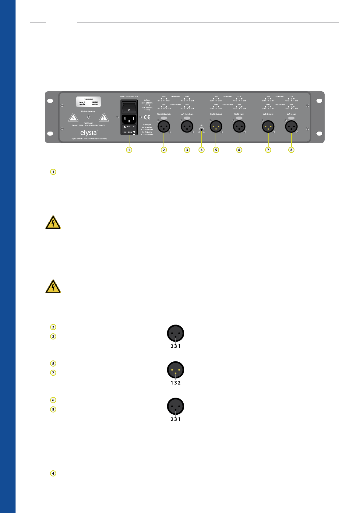
Connectors
Please pay attention to operate the mpressor with the correct voltage setting for your country and
the proper pin assignments on the XLR connectors.
Mains module
This module combines the line cord connector, the on/o switch, the fuse holder with integrated 230/115 VAC voltage selector and a line lter for providing the transformer with
clean current.
WARNING: High voltage
Make sure to disconnect the line cord before replacing eventually blown fuses or changing
the operating voltage of the unit! In order to change the operating voltage, the fuse holder
has to be taken out and re-inserted so that the desired voltage can be read correctly (and is
not standing upside down). Note: Some export versions have a xed voltage of e.g. 100 or
115 VAC and cannot operate at 230 VAC.
WARNING: Fuses
Always make sure to use the correct fuses for the chosen voltage: 230 VAC 0.8 A Slo-Blo or
115 VAC 1.6 A Slo-Blo. Incorrect or missing fuses are dangerous safety hazards for both the
unit and yourself!
Sidechain inputs (+4 dBu)
Pin assignment balanced: 1 ground 2 hot (+) 3 cold (-)
Pin assignment unbalanced: 1 ground 2 hot (+) 3 ground
Audio outputs (+4 dBu)
Pin assignment balanced: 1 ground 2 hot (+) 3 ground
Pin assignment unbalanced: 1 ground 2 hot (+) 3 idle
Audio inputs (+4 dBu)
Pin assignment balanced: 1 ground 2 hot (+) 3 cold (-)
Pin assignment unbalanced: 1 ground 2 hot (+) 3 ground
Note: If a device that is placed before the mpressor in the signal chain has an unbalanced
output stage, a complete mute can eventually occur when the compressor is activated. If
this happens, please follow the advice on page 24.
Brightness trimmer
BASICS – Connectors
8
You can use a small screwdriver to adjust the light intensity of the front panel logo disc.
Page 9

Link Mode
Threshold
Attack
Release
Ratio
GR Limit
SC Extern
Auto Fast
Anti Log
On
In link mode, both channels of the mpressor can be coupled and operated with the controllers and
switches of the left control panel. Please consider the following notes:
Threshold Attack Release Ratio
SC Extern Auto Fast Anti Log
EQ Gain
EQ Freq GR Limit Gain
EQ Gain
EQ Freq
Gain
On x10 On
Left
Right
Link
On x10
Both sides of the mpressor utilize exactly identical electronic modules that could even be interchanged with each other in principle. This grants a high equality of signal processing in the left
and right channel, which is especially important in stereo mode. Another result is the excellent
isolation of both channels from each other, and the audio quality will not decline because there
are no lossy to and fro signal routings in the circuitry.
Note: As an eect of this design approach, only the control functions of the compressor (marked
green in the gure) are combined in link mode. The left control panel becomes the master, that is
the settings for the left channel are transferred to the right channel – therefore the settings of the
particular controllers on the right side are not relevant in link mode.
Note: At the same time this means that the audio functions of the compressor (marked orange) are
not combined. In practice you have to pay attention to set the controllers and switches for both
EQ and gain sections identically. Otherwise an audible drift between the left and the right channel
might occur.
External Sidechain
If the SC Extern switch is active, compression will not be controlled by the signals from the regular
audio inputs anymore, but by dierent audio signals which are fed into the additional sidechain
input connectors.
If a duplicate of the input signal is processed with an equalizer and then fed into the sidechain
input, for example, the result will be frequency-dependent compression. Another example is to
send the bass drum of a drum machine into the sidechain input in order to achieve nice groovy
compression that is pumping in time with the music.
The external sidechain inputs are equipped with a high pass lter that has its cut-o frequency
at 80 Hz with a slew rate of 6 dB per octave. This has been done in order to reduce the inuence
of the low frequencies on overall compression by a certain amount in order to keep the eect as
balanced as possible.
BASICS – Link Mode & External Sidechain
9
Page 10

BASICS
Auto Fast
The attack time parameter is a very crucial factor for the control behavior of a compressor. Therefore choosing the right setting is very important, but depending on the dynamic progress of the
source material this can be a dicult task – no matter if you are processing single channels or
complete mixes.
If a very short time is chosen, the compressor is able to catch the short peaks, but on the other
hand the sustaining signal will also be processed, which might result in audible distortion. Longer attack settings reduce distortion signicantly, but then the compressor is too slow for fast
impulses.
This is where the Auto Fast function comes into play. For example,
if you set the attack to 80 ms and then engage the Auto Fast mode,
the attack time will be shortened automatically on fast and loud
signal impulses. The compressor reduces the signal quickly and
prevents it from slipping through.
Then the attack time directly and automatically returns to its original setting. In Auto Fast mode
the compressor can be very fast, but only when it is really needed. This function inuences the
attack parameter on short and loud impulses only; in all other cases the original setting of the
controller is given priority.
Anti Log
The release parameter, on the other hand, has a strong inuence on the character of the compression being obvious or unobtrusive to the ear. As a general rule, linear or logarithmic release curves
will be employed if a discreet performance of the compressor is required. It is characteristic of a
logarithmic release that the time constant shortens when the gain reduction raises. The advantage of this is that short and loud peaks (e.g. drums) have a fast release time, while the remaining
material is processed with a slower release time.
Gain Reduction
Linear
Anti Log
Time
But if intentionally striking and creative compression as well as
producing new and interesting sounds are the sought-after goals,
it denitely makes sense to turn the established approach upside
down. For this reason, you can switch the release curve of the
mpressor from linear to antilogarithmic.
10
Compared to the logarithmic release curve, the eect of the Anti Log option behaves just the
other way round: When the threshold point is passed and compression starts, the release time
is longer in the beginning. However, when the input signal starts to decline, the release time becomes faster.
A special circuitry makes the process independent from the absolute amount of gain reduction.
No matter if the compressor reduces 10, 15 or 20 dB, the curve will always stay the same at the
start and will only become faster at the end. Consequently, many exceptional compression eects
can be created just by pushing a button.
BASICS – Auto Fast & Anti Log
Page 11

Gain Reduction Limiter
A specialty of the mpressor is the Gain Reduction Limiter for the control voltage of the compressor.
This limiter is not placed in the audio path where you would usually nd it, but in the control path
of the compressor. When it is activated, it limits the control voltage according to the setting of the
controller. This means: No matter how high the input level might become – the amount of gain
reduction will never exceed the value which is set with the GR Limit controller.
Gain Reduction
For comparison, just imagine a fader on a mixing console with your
hand moving the fader to ‘play compressor’. If now the fader was
Standard
GR Limiter
Time
limited by a piece of duct tape at 10 dB, for example, it could only
reduce the signal up to this value. If the input level dropped below
this limit, the fader would be moved up correspondingly.
However, if the input signal got even louder, the fader could not be moved down any further
because of the duct tape limit, and then the output signal would become louder again in correspondence with the input signal.
Output
Loud parts in an arrangement can keep their dynamics, as they will
not be compressed beyond the limit of the Gain Reduction Limiter.
Some very nice special eects like ducking or upward compression
Level
Compression
Input
can be achieved with it easily by only reducing the quieter parts
without changing the original dynamics at the same time.
Niveau Filter
This lter is a specialist in changing the overall sonic character of a track with ease. It features two
controllers per channel and is capable of producing convincing results exibly in no time at all.
Whenever a classic shelving lter would be too limited and a fully parametric lter would be too
much, the Niveau Filter is the perfect tool.
Gain
EQ Gain High
Its main function is to change the proportions between high and
low frequencies. The principle is quite similar to a pair of scales: Dependent on the gain setting around a variable center frequency,
EQ Gain Low
Frequency
the high frequencies are boosted whereas the low frequencies are
attenuated (or vice versa).
By simultaneously boosting and cutting the selected frequency areas, it is much easier to inuence the character of a track (‚bright‘ vs. ‚dark‘) compared to using other types of equalizers. The
center frequency can be shifted continuously between 26 Hz and 2.2 kHz or between 260 Hz and
22 kHz respectively (when the x10 switch is activated).
Gain
The characteristics of the lter change in the extreme positions of
the EQ Gain controller: the fully counter-clockwise setting will produce a low pass lter; fully clockwise position will result in a high
Low PassHigh Pass
Frequency
pass lter. The overall level can drop quite noticeably then, but this
can be corrected with the gain controller easily.
BASICS – Gain Reduction Limiter & Niveau Filter
11
Page 12

Threshold
16
14
9
5
0
-5 -8
-13
-15
-17
-18
dB
Attack
0,01
1,0
5,0
8,0
13
17 21
70
100
140
150
ms
Release
5
7
12
26
50
85 150
380
600
930
1k2
ms
1,2
1,3
1,6
2,0
5,0 10
-0,3
-1,0
-2,0
-3,0
-4,0
1:X
Ratio
EQ Gain
Lo
6,0
4,5
3,0
2,0
1,0 1,0
3,0
4,5
6,0
Hi
dB
EQ Freq
26
28
36
52
90
200 260
450
700
1k3
2k2
Hz
GR Limit
21
19
17
15
13
11 9
5
3
1,5
0
dB
EQ Gain
Lo
6,0
4,5
3,0
2,0
1,0 1,0
3,0
4,5
6,0
Hi
dB
EQ Freq
26
28
36
52
90
200 260
450
700
1k3
2k2
Hz
GR Limit
21
19
17
15
13
11 9
5
3
1,5
0
dB
On
x10
On
SC Extern
Auto Fast
Anti Log
SC Extern
Auto Fast
Anti Log
On
x10
On
SCENARIOS
Threshold
-13
-15
-17
17 21
13
8,0
5,0
1,0
150
0,01
ms
-5 -8
0
5
9
14
-18
16
dB
Attack
85 150
50
70
26
100
12
140
7
1k2
5
ms
Release
380
600
930
5,0 10
Ratio
-0,3
-1,0
2,0
1,6
-2,0
1,3
-3,0
1,2
-4,0
1:X
4,0 6,0
Gain
3,0
10
2,0
1,0
13
17
0,5
20
0
dB
Left
Right
Link
4,0 6,0
Gain
3,0
10
2,0
1,0
13
17
0,5
20
0
dB
Standard Compression
Because of the well-balanced adjustment of its parameters, the mpressor is suited perfectly for
many applications in everyday studio business. The settings shown in the above gure provide a
good starting position for ‘normal’ compression jobs like vocals, choirs, guitars, drums, keyboards
and so on.
Moderate ratios from 1:2 to 1:5 and release times around 300 ms make a good basis for further
parameter variations. The threshold controller can now be used to adjust the desired amount of
gain reduction. Depending on the source material, the EQ section can be used additionally with
great benet.
It denitely pays o to spend some time on getting to know this interesting feature of the mpressor and what it can do for your sound. The Gain Reduction Limiters oer completely new possibilities, too, and therefore should be given a try soon by all means.
Threshold
-13
-15
-17
17 21
13
8,0
5,0
1,0
150
0,01
ms
-5 -8
0
5
9
14
-18
16
dB
Attack
85 150
50
70
26
100
12
140
7
1k2
5
ms
Release
380
600
930
5,0 10
Ratio
-0,3
-1,0
2,0
1,6
-2,0
1,3
-3,0
1,2
-4,0
1:X
4,0 6,0
Gain
3,0
10
2,0
1,0
13
17
0,5
20
0
dB
Left
Right
Link
4,0 6,0
Gain
3,0
10
2,0
1,0
13
17
0,5
20
0
dB
Big Drums
In this case, a complete drum mix is processed with the mpressor. The intensity of audible transients is determined by the attack time. If this parameter is very short, only the rst milliseconds of
the signal will be emphasized, whereas longer settings will come closer to its original structure.
The release controller can now be used to adjust the ‘loudness’ (shorter settings produce louder
signals), at which longer settings will also give you an inuence on the groove of a track. If high ratios are applied, this eect will become more and more extreme. You could also use the GR Limiter
additionally in order to reduce the maximum amount of reduction for very energetic drums.
As a result, the drums become very punchy – with beautiful attacks that can really shine in a mix. An
increased amount of ambience is generated on top of it, resulting in a loud and massive sound.
SCENARIOS – Standard Compression & Big Drums
12
Page 13

Threshold
16
14
9
5
0
-5 -8
-13
-15
-17
-18
dB
Attack
0,01
1,0
5,0
8,0
13
17 21
70
100
140
150
ms
Release
5
7
12
26
50
85 150
380
600
930
1k2
ms
1,2
1,3
1,6
2,0
5,0 10
-0,3
-1,0
-2,0
-3,0
-4,0
1:X
Ratio
EQ Gain
Lo
6,0
4,5
3,0
2,0
1,0 1,0
3,0
4,5
6,0
Hi
dB
EQ Freq
26
28
36
52
90
200 260
450
700
1k3
2k2
Hz
GR Limit
21
19
17
15
13
11 9
5
3
1,5
0
dB
EQ Gain
Lo
6,0
4,5
3,0
2,0
1,0 1,0
3,0
4,5
6,0
Hi
dB
EQ Freq
26
28
36
52
90
200 260
450
700
1k3
2k2
Hz
GR Limit
21
19
17
15
13
11 9
5
3
1,5
0
dB
Threshold
On
x10
On
SC Extern
Anti Log
SC Extern
Auto Fast
Anti Log
On
x10
On
Threshold
16
14
9
5
0
-5 -8
-13
-15
-17
-18
dB
Attack
0,01
1,0
5,0
8,0
13
17 21
70
100
140
150
ms
Release
5
7
12
26
50
85 150
380
600
930
1k2
ms
1,2
1,3
1,6
2,0
5,0 10
-0,3
-1,0
-2,0
-3,0
-4,0
1:X
Ratio
GR Limit
21
19
17
15
13
11 9
5
3
1,5
0
dB
GR Limit
21
19
17
15
13
11 9
5
3
1,5
0
dB
On
SC Extern
SC Extern
Auto Fast
Anti Log
On
-13
-15
-17
17 21
13
8,0
5,0
1,0
150
0,01
ms
-5 -8
0
5
9
14
-18
16
dB
Attack
85 150
50
70
26
100
12
140
7
Auto Fast
1k2
5
ms
Release
380
600
930
5,0 10
Ratio
-0,3
-1,0
2,0
1,6
-2,0
1,3
-3,0
1,2
-4,0
1:X
4,0 6,0
Gain
3,0
10
2,0
1,0
13
17
0,5
20
0
dB
Left
Right
Link
4,0 6,0
Gain
3,0
10
2,0
1,0
13
17
0,5
20
0
dB
Smashed Drums
If the drums are supposed to sound extremely compressed and loud, this setting can be used to
limit almost the entire signal so that there is nearly no dynamics remaining. The Auto Fast function
for the attack parameter makes sure that the mpressor works fast but undistorted, and fast release
times of about 50 ms are responsible for the loudness.
The ratio controller is set to 1:10 which makes the mpressor act like a kind of fast brickwall limiter.
The drums now sound as if they had been recorded with a focus on the room microphones: little
transients, lots of ambience and long sustaining toms and cymbals.
If this signal is now routed to a separate fader of a console and then mixed to the unprocessed
original, the result will be the typical parallel compression which is very popular for this kind of
application.
0
5
9
14
2,0
3,0
4,5
6,0
-5 -8
16
dB
1,0 1,0
Lo
dB
Threshold
-13
8,0
-15
5,0
1,0
-17
-18
EQ Gain
3,0
4,5
36
6,0
On x10
Hi
17 21
13
0,01
ms
200 260
90
52
28
26
Hz
Attack
50
70
26
100
12
140
7
Auto Fast Anti Log
150
5
EQ Freq
450
700
1k3
2k2
85 150
1k2
ms
Release
380
600
930
5,0 10
Ratio
-0,3
-1,0
2,0
1,6
-2,0
1,3
-3,0
1,2
-4,0
1:X
4,0 6,0
Gain
3,0
10
2,0
1,0
13
17
0,5
20
0
dB
Left
Right
Link
2,0
3,0
4,5
6,0
1,0 1,0
Lo
dB
EQ Gain
3,0
52
4,5
36
28
6,0
On x10
Hi
200 260
EQ Freq
90
450
700
1k3
2k2
26
Hz
4,0 6,0
Gain
3,0
10
2,0
1,0
13
17
0,5
20
0
dB
Reverse Sounds
Because the mpressor also features negative ratios, you can perfectly use it to create weird really
way-out eects: Signals sound like if they were played backwards and become louder in their progression. Very loud input signals are reduced by large amounts which creates the reverse eect.
The Auto Fast function for the attack parameter is used to perform the control process fast and
free from distortion. The position of the release controller determines the traits the sound will get
louder with. The Anti Log mode should also been tried on top of that, as it will even increase the
intensity of the reverse eect.
A good balance of the threshold, release and ratio parameters is very important for this application. Settings like these result in the amount of gain reduction exceeding the 20 dB mark quite
often, therefore adequate settings of the gain controller have to be made for compensation.
SCENARIOS – Smashed Drums & Reverse Sounds
13
Page 14

Threshold
16
14
9
5
0
-5 -8
-13
-15
-17
-18
dB
Attack
0,01
1,0
5,0
8,0
13
17 21
70
100
140
150
ms
Release
5
7
12
26
50
85 150
380
600
930
1k2
ms
1,2
1,3
1,6
2,0
5,0 10
-0,3
-1,0
-2,0
-3,0
-4,0
1:X
Ratio
EQ Gain
Lo
6,0
4,5
3,0
2,0
1,0 1,0
3,0
4,5
6,0
Hi
dB
EQ Freq
26
28
36
52
90
200 260
450
700
1k3
2k2
Hz
EQ Gain
Lo
6,0
4,5
3,0
2,0
1,0 1,0
3,0
4,5
6,0
Hi
dB
EQ Freq
26
28
36
52
90
200 260
450
700
1k3
2k2
Hz
GR Limit
21
19
17
15
13
11 9
5
3
1,5
0
dB
On
x10
SC Extern
Auto Fast
Anti Log
SC Extern
Auto Fast
Anti Log
On
x10
On
Threshold
16
14
9
5
0
-5 -8
-13
-15
-17
-18
dB
Attack
0,01
1,0
5,0
8,0
13
17 21
70
100
140
150
ms
Release
5
7
12
26
50
85 150
380
600
930
1k2
ms
1,2
1,3
1,6
2,0
5,0 10
-0,3
-1,0
-2,0
-3,0
-4,0
1:X
Ratio
EQ Gain
Lo
6,0
4,5
3,0
2,0
1,0 1,0
3,0
4,5
6,0
Hi
dB
EQ Freq
26
28
36
52
90
200 260
450
700
1k3
2k2
Hz
GR Limit
21
19
17
15
13
11 9
5
3
1,5
0
dB
Gain
10
13
17
0
0,5
2,0
3,0
4,0 6,0
20
dB
1,0
Auto Fast
Anti Log
SC Extern
Auto Fast
Anti Log
On
x10
On
Right
Link
SCENARIOS
Threshold
-13
-15
-17
17 21
13
8,0
5,0
1,0
150
0,01
ms
-5 -8
0
5
9
14
-18
16
dB
Attack
85 150
50
70
26
100
12
140
7
1k2
5
ms
11 9
13
15
17
19
21
dB
Release
380
600
930
GR Limit
0
5,0 10
Ratio
-0,3
-1,0
2,0
1,6
-2,0
1,3
-3,0
1,2
-4,0
1:X
4,0 6,0
Gain
3,0
5
3
1,5
On
10
2,0
1,0
13
17
0,5
20
0
dB
Left
Right
Link
4,0 6,0
Gain
3,0
10
2,0
1,0
13
17
0,5
20
0
dB
Transient Enhancer
A special task is to emphasize the transients at the beginning of a tone, chord and so on. The
Gain Reduction Limiter is of special importance in this scenario. The chosen parameters result in a
rather strong compression with quite fast release times and even negative ratios.
Without the limiter the signal would be compressed much too strongly; 10 to 15 dB of gain reduction would occur quite regularly in this case. But now the limiter comes into play by reducing
maximum amount of gain reduction to 6 dB. If now the gain controller is also set to 6 dB, the signal
will be boosted by 6 dB at its beginning and will then be held at 0 dB in its further course.
If for example an organ is processed this way, it sounds rmer as its transients receive an accentuation. And no matter if a single note or a full chord is played – the output level will always stay the
same, so that the result does not sound like typical compression.
-5 -8
Threshold
0
5
9
14
16
dB
1,0 1,0
2,0
3,0
4,5
6,0
Lo
dB
13
-13
8,0
-15
5,0
1,0
-17
SC Extern
0,01
-18
EQ Gain
3,0
52
4,5
36
28
6,0
On x10 On
Hi
17 21
150
ms
200 260
90
26
Hz
85 150
Attack
50
70
26
100
12
140
7
1k2
5
ms
11 9
EQ Freq
13
450
15
700
17
19
1k3
2k2
21
dB
Release
380
600
930
GR Limit
0
5,0 10
Ratio
-0,3
-1,0
2,0
1,6
-2,0
1,3
-3,0
1,2
-4,0
1:X
4,0 6,0
Gain
3,0
5
3
1,5
10
2,0
1,0
13
17
0,5
20
0
dB
Left
Groove Ducking
The external sidechain input can be used to achieve specic groovy eects. Here the sidechain
is triggered by a rhythmical signal like a 4 beat bass drum. The audio path can carry any desired
sounds which are then reduced in the rhythm of the bass drum and therefore start to groove in
sync with that beat.
Especially the release parameter can be used to adapt the timing of the eect to the tempo of the
song, whereas the Anti Log mode oers interesting variations. If, for example, a 16 beat HiHat is
processed in this way, it will benet from a nice vivid groove it will now move in.
Bass sounds can now receive a stronger accentuation, as the ducking eect creates more space
in the mix and the focus is shifted more onto the 4 beat bass drum. If the mpressor is inserted
into the subgroup of a mixing console, you will also be able to trigger an arrangement of various
instruments etc. via the external sidechain.
SCENARIOS – Transient Enhancer & Groove Ducking
14
Page 15

Threshold
16
14
9
5
0
-5 -8
-13
-15
-17
-18
dB
Attack
0,01
1,0
5,0
8,0
13
17 21
70
100
140
150
ms
Release
5
7
12
26
50
85 150
380
600
930
1k2
ms
1,2
1,3
1,6
2,0
5,0 10
-0,3
-1,0
-2,0
-3,0
-4,0
1:X
Ratio
GR Limit
21
19
17
15
13
11 9
5
3
1,5
0
dB
EQ Gain
Lo
6,0
4,5
3,0
2,0
1,0 1,0
3,0
4,5
6,0
Hi
dB
EQ Freq
26
28
36
52
90
200 260
450
700
1k3
2k2
Hz
GR Limit
21
19
17
15
13
11 9
5
3
1,5
0
dB
Gain
10
13
17
0
0,5
2,0
3,0
4,0 6,0
20
dB
1,0
Threshold
x10
On
Auto Fast
SC Extern
Auto Fast
Anti Log
On
x10
On
Right
Link
Threshold
16
14
9
5
0
-5 -8
-13
-15
-17
-18
dB
Attack
0,01
1,0
5,0
8,0
13
17 21
70
100
140
150
ms
Release
5
7
12
26
50
85 150
380
600
930
1k2
ms
1,2
1,3
1,6
2,0
5,0 10
-0,3
-1,0
-2,0
-3,0
-4,0
1:X
Ratio
GR Limit
21
19
17
15
13
11 9
5
3
1,5
0
dB
Auto Fast
Anti Log
SC Extern
Auto Fast
Anti Log
On
-13
-15
-17
EQ Gain
3,0
4,5
6,0
Hi
SC Extern
17 21
13
8,0
5,0
1,0
150
0,01
ms
200 260
90
52
36
28
On
26
Hz
-5 -8
0
5
9
14
-18
16
dB
1,0 1,0
2,0
3,0
4,5
6,0
Lo
dB
85 150
Attack
50
70
26
100
12
140
7
1k2
5
ms
EQ Freq
450
700
1k3
2k2
Release
380
600
930
5,0 10
Ratio
-0,3
-1,0
2,0
1,6
-2,0
1,3
Anti Log
-3,0
1,2
-4,0
1:X
4,0 6,0
Gain
3,0
10
2,0
1,0
13
17
0,5
20
0
dB
Left
Negative Gating
An interesting variant of the groove ducking technique is negative gating that is based on faster
release times and uses the Anti Log mode. Higher ratios are also very typical for this process. If now
a bass drum is fed into the external sidechain input as a trigger signal, for example, the compressor
will reduce the audio signal by a signicant amount, resulting in gain reduction values of 30 and
40 dB.
After the trigger signal has faded away, the gain reduction value is kept constant by the Anti Log
function for a moment, after which it rebounds rapidly. This special envelope makes the eect
almost sound like a gate – but with the dierence that the signal is made quieter instead of being
totally muted.
If you want the eect to be as stable as possible, please take care that the trigger signals have even
attacks and levels.
-5 -8
Threshold
0
5
9
14
16
dB
1,0 1,0
2,0
3,0
4,5
6,0
Lo
dB
13
-13
8,0
-15
5,0
1,0
-17
SC Extern
0,01
-18
EQ Gain
90
3,0
52
4,5
36
28
6,0
On x10 On
Hi
17 21
150
ms
200 260
26
Hz
85 150
Attack
50
70
26
100
12
140
7
1k2
5
ms
11 9
EQ Freq
13
450
15
700
17
19
1k3
2k2
21
dB
Release
380
600
930
0
GR Limit
5
3
1,5
5,0 10
Ratio
-0,3
-1,0
2,0
1,6
-2,0
1,3
-3,0
1,2
-4,0
1:X
4,0 6,0
Gain
3,0
10
2,0
1,0
13
17
0,5
20
0
dB
Left
Right
Link
2,0
3,0
4,5
6,0
1,0 1,0
Lo
dB
EQ Gain
3,0
52
4,5
36
28
6,0
On x10
Hi
200 260
EQ Freq
90
450
700
1k3
2k2
26
Hz
4,0 6,0
Gain
3,0
10
2,0
1,0
13
17
0,5
20
0
dB
Ducking FX
Using the mpressor in combination with eect units like reverb, delay or chorus will result in fascinating results. The important point in this case is that compression is applied after the signal has
passed the eects processor. The external sidechain input, however, is fed with the original dry
signal that is also fed into the input of the FX unit.
If a drum track is processed with a reverb, for example, the reverberation can be compressed extremely strong so that it will almost vanish in very loud parts at rst. It sounds dierent than only
compressing the reverberation without using the external sidechain, because now it depends on
the dynamics of the original signal.
An electric piano which is processed with chorus and delay eects can benet from this technique, too, as the chorus/delay eect will become more and more prominent while the played
note decreases in volume. Here it is important that all eect units only send the pure eect signal
(100 % wet) which is then mixed to the dry signal on a parallel track.
SCENARIOS – Negative Gating & Ducking FX
15
Page 16

Threshold
16
14
9
5
0
-5 -8
-13
-15
-17
-18
dB
Attack
0,01
1,0
5,0
8,0
13
17 21
70
100
140
150
ms
Release
5
7
12
26
50
85 150
380
600
930
1k2
ms
1,2
1,3
1,6
2,0
5,0 10
-0,3
-1,0
-2,0
-3,0
-4,0
1:X
Ratio
GR Limit
21
19
17
15
13
11 9
5
3
1,5
0
dB
GR Limit
21
19
17
15
13
11 9
5
3
1,5
0
dB
On
SC Extern
Auto Fast
SC Extern
Auto Fast
Anti Log
On
Threshold
16
14
9
5
0
-5 -8
-13
-15
-17
-18
dB
Attack
0,01
1,0
5,0
8,0
13
17 21
70
100
140
150
ms
Release
5
7
12
26
50
85 150
380
600
930
1k2
ms
1,2
1,3
1,6
2,0
5,0 10
-0,3
-1,0
-2,0
-3,0
-4,0
1:X
Ratio
EQ Gain
Lo
6,0
4,5
3,0
2,0
1,0 1,0
3,0
4,5
6,0
Hi
dB
EQ Freq
26
28
36
52
90
200 260
450
700
1k3
2k2
Hz
GR Limit
21
19
17
15
13
11 9
5
3
1,5
0
dB
Gain
10
13
17
0
0,5
2,0
3,0
4,0 6,0
20
dB
1,0
SC Extern
Auto Fast
SC Extern
Auto Fast
Anti Log
On
x10
On
Right
Link
SCENARIOS
0
5
9
14
2,0
3,0
4,5
6,0
-5 -8
16
dB
1,0 1,0
Lo
dB
Threshold
-13
8,0
-15
5,0
-17
-18
EQ Gain
3,0
4,5
6,0
On x10
Hi
17 21
13
1,0
150
0,01
ms
200 260
90
52
36
28
26
Hz
85 150
Attack
50
70
26
100
12
140
7
1k2
5
ms
EQ Freq
450
700
1k3
2k2
Release
380
600
930
5,0 10
Ratio
-0,3
-1,0
2,0
1,6
-2,0
1,3
Anti Log
-3,0
1,2
-4,0
1:X
4,0 6,0
Gain
3,0
10
2,0
1,0
13
17
0,5
20
0
dB
Left
Right
Link
1,0 1,0
2,0
3,0
4,5
6,0
Lo
dB
EQ Gain
3,0
52
4,5
36
28
6,0
On x10
Hi
200 260
EQ Freq
90
450
700
1k3
2k2
26
Hz
4,0 6,0
Gain
3,0
10
2,0
1,0
13
17
0,5
20
0
dB
Distorted Compression
By using very fast time constants, the mpressor can also be abused to create special distortion
sounds. To do so, set the attack controller to its minimum of 0.01 ms and the release time also to
its fastest value of 5.0 ms.
Now the compressor becomes so fast that it compresses and twists almost every single wave form
separately. The result sounds similar to a distortion unit, but without the usual drawback that the
noise oor of the input signal is amplied.
If the Niveau Filter is used in its low pass position in addition, everything will start to sound in a
wonderful LoFi style. Especially bass and drums are ideal instruments for being processed in this
way.
-5 -8
Threshold
0
5
9
14
16
dB
1,0 1,0
2,0
3,0
4,5
6,0
Lo
dB
13
-13
8,0
-15
5,0
1,0
-17
0,01
-18
EQ Gain
3,0
52
4,5
36
28
6,0
On x10 On
Hi
17 21
150
ms
200 260
90
26
Hz
85 150
Attack
50
70
26
100
12
140
7
1k2
5
ms
11 9
EQ Freq
13
450
15
700
17
19
1k3
2k2
21
dB
Release
380
600
930
GR Limit
0
5,0 10
Ratio
-0,3
-1,0
2,0
1,6
-2,0
1,3
Anti Log
5
3
1,5
-3,0
1,2
-4,0
1:X
4,0 6,0
Gain
3,0
10
2,0
1,0
13
17
0,5
20
0
dB
Left
Delay Loops
Delay and compressor in a loop – does that make any sense at all? Denitively yes, because this
combination is a truly rich source for lots of crazy sounds! In this scenario, the mpressor is placed
before a delay which is connected to an input of a mixing console. The feedback parameter of the
delay has to be set to 0, because the feedback is generated with the aux send of the specic channel of the console.
If the gain controller of the compressor is now set in a way that the delay sound becomes louder
with every repetition, it will nally fall into a feedback loop which is kept steady by the compressor.
If the Niveau Filter is used in addition to bend the frequency response, very noisy, pumping and
breathing sounds that keep changing continuously will be the result.
Very short delay times between 5 and 30 ms can even generate oscillating sounds that instantly
remind of synthesizers. Turning the Niveau Filter controllers during this process results in a shift of
the frequency response with each repetition of the delay.
SCENARIOS – Distorted Compression & Delay Loops
16
Page 17

Threshold
16
14
9
5
0
-5 -8
-13
-15
-17
-18
dB
Attack
0,01
1,0
5,0
8,0
13
17 21
70
100
140
150
ms
Release
5
7
12
26
50
85 150
380
600
930
1k2
ms
1,2
1,3
1,6
2,0
5,0 10
-0,3
-1,0
-2,0
-3,0
-4,0
1:X
Ratio
EQ Gain
Lo
6,0
4,5
3,0
2,0
1,0 1,0
3,0
4,5
6,0
Hi
dB
EQ Freq
26
28
36
52
90
200 260
450
700
1k3
2k2
Hz
EQ Gain
Lo
6,0
4,5
3,0
2,0
1,0 1,0
3,0
4,5
6,0
Hi
dB
EQ Freq
26
28
36
52
90
200 260
450
700
1k3
2k2
Hz
GR Limit
21
19
17
15
13
11 9
5
3
1,5
0
dB
Gain
10
13
17
0
0,5
2,0
3,0
4,0 6,0
20
dB
1,0
Threshold
On
x10
SC Extern
Auto Fast
SC Extern
Auto Fast
Anti Log
On
x10
On
Right
Link
Threshold
16
14
9
5
0
-5 -8
-13
-15
-17
-18
dB
Attack
0,01
1,0
5,0
8,0
13
17 21
70
100
140
150
ms
Release
5
7
12
26
50
85 150
380
600
930
1k2
ms
1,2
1,3
1,6
2,0
5,0 10
-0,3
-1,0
-2,0
-3,0
-4,0
1:X
Ratio
GR Limit
21
19
17
15
13
11 9
5
3
1,5
0
dB
SC Extern
Auto Fast
SC Extern
Auto Fast
Anti Log
On
-13
-15
-17
17 21
13
8,0
5,0
1,0
150
0,01
ms
-5 -8
0
5
9
14
-18
16
dB
Attack
85 150
50
70
26
100
12
140
7
1k2
5
ms
11 9
13
15
17
19
21
dB
Release
380
600
930
0
GR Limit
5
3
1,5
5,0 10
Ratio
-0,3
-1,0
2,0
1,6
-2,0
1,3
Anti Log
-3,0
1,2
-4,0
1:X
4,0 6,0
Gain
3,0
10
2,0
1,0
13
17
0,5
On
20
0
dB
Left
Frequency Compression
The external sidechain also makes it possible to apply frequency dependent compression. This
means that the compressor selectively reacts stronger or weaker to certain frequencies.
One of the most typical applications of this technique is de-essing: The input signal is multed to a
parallel line before the mpressor and then fed into an equalizer that raises the S sounds and lowers
all other frequency areas. This processed signal is then send into the external sidechain input of
the compressor which will only react to strong S sounds as a result.
Depending on the settings of the EQ, it is also possible to use combinations of normal compression and de-essing. This can be achieved by only boosting the frequencies of the S sounds without
cutting anything else. Another variant is to only lower the bass area on the external EQ so that
these frequencies will not dominate the compression process so strongly anymore, which will
result in an increase of overall loudness.
-5 -8
Threshold
0
5
9
14
16
dB
1,0 1,0
2,0
3,0
4,5
6,0
Lo
dB
13
-13
8,0
-15
5,0
1,0
-17
0,01
-18
EQ Gain
90
3,0
52
4,5
36
28
6,0
On x10 On
Hi
17 21
150
ms
200 260
26
Hz
85 150
Attack
50
70
26
100
12
140
7
1k2
5
ms
11 9
EQ Freq
13
450
15
700
17
19
1k3
2k2
21
dB
Release
380
600
930
0
GR Limit
5
3
1,5
5,0 10
Ratio
-0,3
-1,0
2,0
1,6
-2,0
1,3
Anti Log
-3,0
1,2
-4,0
1:X
4,0 6,0
Gain
3,0
10
2,0
1,0
13
17
0,5
20
0
dB
Left
Right
Link
2,0
3,0
4,5
6,0
1,0 1,0
Lo
dB
EQ Gain
3,0
52
4,5
36
28
6,0
On x10
Hi
200 260
EQ Freq
90
450
700
1k3
2k2
26
Hz
4,0 6,0
Gain
3,0
10
2,0
1,0
13
17
0,5
20
0
dB
Mix Buss
The mpressor also proves of value when used as a high class mix buss compressor, especially when
it comes to the more vehement genres like rock and electronic music. If you use it straight on from
the beginning of a mix, you will automatically adapt your mix to the sound this produces.
The proportions between the levels of the separate tracks will be attuned perfectly to the active
compressor. This kind of mixing especially makes sense if the complete basic sound is supposed
to dier from the ‘standard’ sound of other productions.
If you want a track to sound very groovy and pumping, for example, just mix the drums louder as
usually so that they dominate the compression process. All other instruments which are quieter in
the mix now groove in conformity with the drums and become very vivid thereby.
SCENARIOS – Frequency Compression & Mix Buss
17
Page 18

REFERENCE
THD Analysis
This diagram shows the FFT spectrum with a sine wave of 1 kHz at 0 dBu. The additionally generated second and third harmonics at 2 kHz and 3 kHz which make the processed signals sound
richer and more interesting become very obvious here. These harmonics are generated in the
transconductance amplier stages of the mpressor. Their amount is dependent on the input level:
the higher it is, the more harmonics are produced. As the gain controller is placed directly in the
input stage, it will also inuence the intensity of added harmonics.
Threshold
The next gure shows a number of dierent threshold points. The settings of threshold and ratio
should always be considered as a couple: If a high ratio is applied, the threshold will usually be in
the lower range in order not to produce a too high amount of gain reduction. If lower ratio settings
are chosen, though, the threshold will be turned more clockwise as a general rule. The complete
control range covers a total of 34 dB, oering the complete variety from very sensitive processing
up to the most extreme eect settings.
18
REFERENCE – THD Analysis & Threshold
Page 19
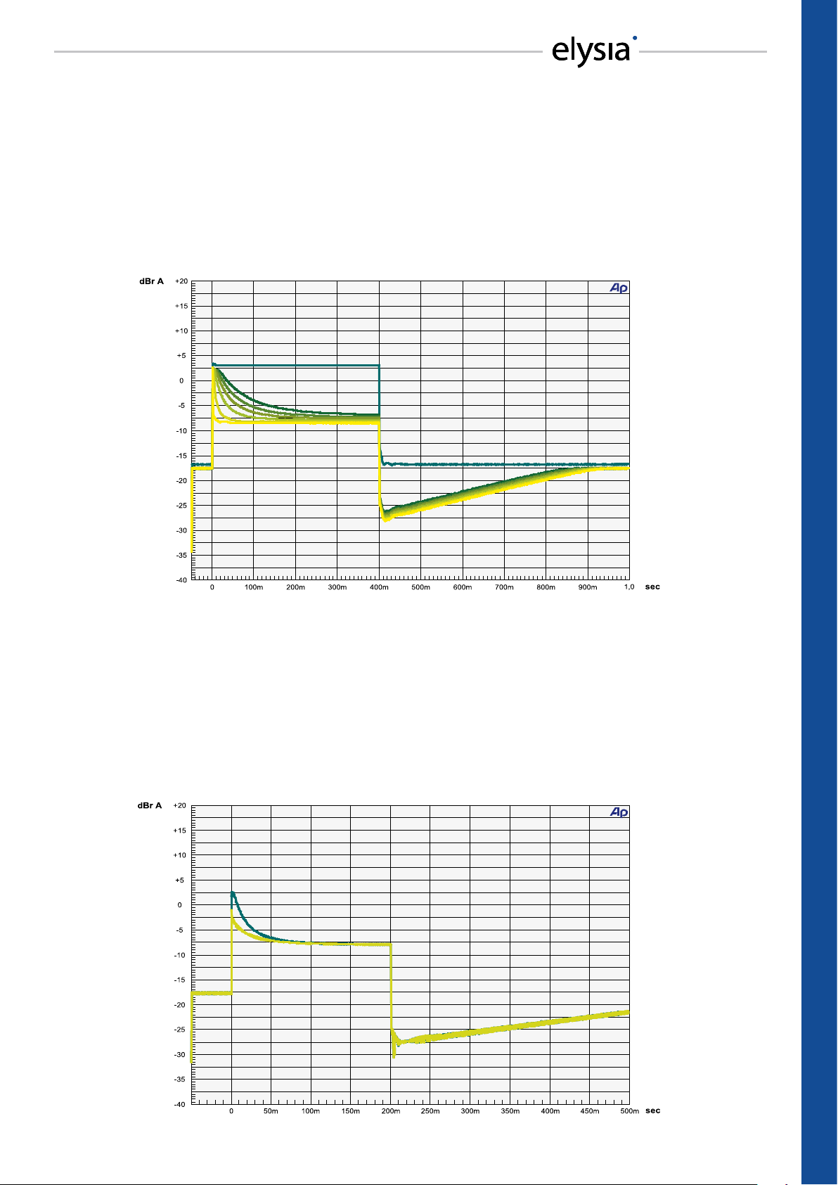
Attack
Here we see how a burst signal (a sine wave which is boosted by 20 dB for a period of 400 ms in this
case) is used to demonstrate the eectiveness of the attack controller. The dierent curves show
how fast the jump in level is reduced by 10 dB. When fast settings are applied, the reduction only
needs a few milliseconds. Longer settings, on the other hand, do not only need a longer period of
time, but also produce a smaller overall amount of decrease in level. Therefore fast attacks always
produce higher amounts of gain reduction than longer ones.
Auto Fast
Based on using a burst signal again, this diagram shows the comparison between a normal attack time of 200 ms (darker curve) and the attack characteristic with activated Auto Fast function
(lighter curve). You can easily see how fast the circuit reacts, as even the rst waves of the burst are
already reduced by 3 dB. On top, the overall amount of gain reduction happens much faster then.
Note: This function starts working at about -3 dB, because lesser amounts of gain reduction do not
include sucient changes in dynamics.
19
REFERENCE – Attack & Auto Fast
Page 20

REFERENCE
Release
This gure is based on a very fast attack time which produces -6 dB of gain reduction. The burst
lasts for 50 ms and then follows the release phase with its time parameter set to dierent lengths.
The linear characteristic of the release curve is easy to see here. Arising from the circuit used for
this process, the attack time has to be added to the release time. The advantage of this is that in
combination with long attack settings you can use even the fastest release settings without generating unwanted artifacts.
Anti Log
This diagram reveals the characteristics of the Anti Log function. The darker curve shows the normal linear release progress, which has a constant ratio of time per dB. In Anti Log mode, however,
the release time is longer when the process starts and becomes shorter in the further progress.
Please note that a certain amount of dynamics is needed in order to form this special curve in its
complete shape: The change from deceleration to acceleration does not happen until an amount
of around 10 dB of gain reduction is reached – and then you will start to really hear it ;-)
20
REFERENCE – Release & Anti Log
Page 21

Ratio
The mpressor is a typical hard knee compressor, which can be seen in this diagram very obviously.
Compression directly starts with the full adjusted ratio in the very moment the input signal passes
the threshold point. Compared to a soft knee characteristic, this kind of compression is more on
the noticeable and audible side. The gure also shows the negative ratios: The characteristic curve
bends and returns back down. The louder the input signal becomes with a setting like that, the
lower the output signal becomes – perfect for spacy compression eects.
dBu
dBu
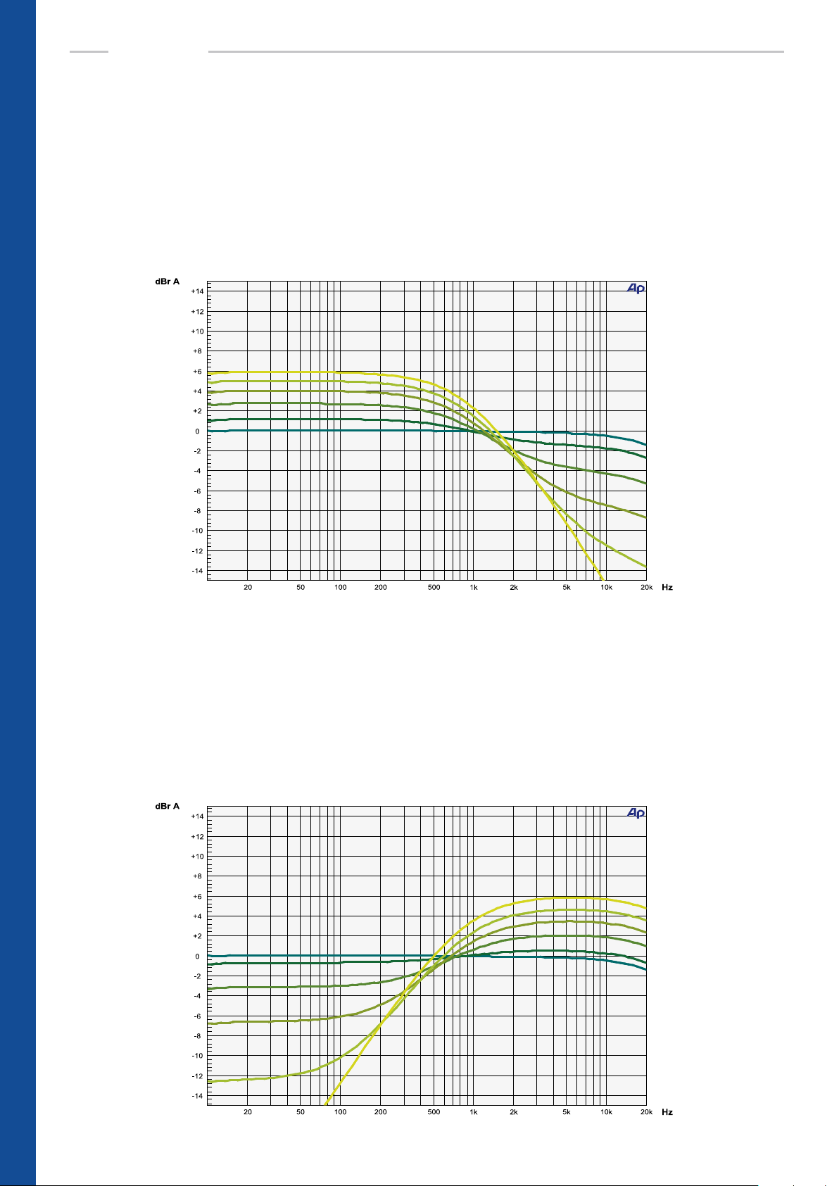
EQ Frequency
This diagram shows a variation of center frequencies with the EQ gain controller in the clockwise
+4 dB position. The x10 button shifts the complete frequency range by a factor of 10. Settings
in the border areas of the covered frequencies make it also possible to create ‘almost’ shelving
lters, but then the overall level likely needs to be adapted with the gain controller. This lter is
as eective as it is easy to use – the perfect tool for applying subtle or strong sonic marks to the
compressed signal in no time at all.
21
REFERENCE – Ratio & EQ Frequency
Page 22
REFERENCE
EQ Gain Low
This measurement shows dierent settings of the EQ gain controller between middle and fully
counter-clockwise position at a center frequency of 1.5 kHz. The diagram shows the eectiveness
of the lter: The lower frequencies are boosted up to 6 dB, then the curve crosses zero at the center
frequency. The high frequencies are attenuated at the same time, and in the extreme setting of
the controller even a 6 dB low pass lter is available. Depending on the setting of the EQ gain, the
overall level possibly needs to be adapted with the gain controller.
EQ Gain High
Here we have the opposite scenario. In this gure the EQ gain controller is turned from 0 to fully
clockwise position at a center frequency of 500 kHz. Contrary to the previous example, the high
frequencies are now boosted up to 6 dB and the lower frequencies are attenuated in a way that
the most extreme setting produces a 6 dB high pass. This special characteristic of the lter provides a broad spectrum of sound shaping possibilities, ranging from very subtle to extremely obvious sonic changes.
22
REFERENCE – EQ Gain Low & EQ Gain High
Page 23
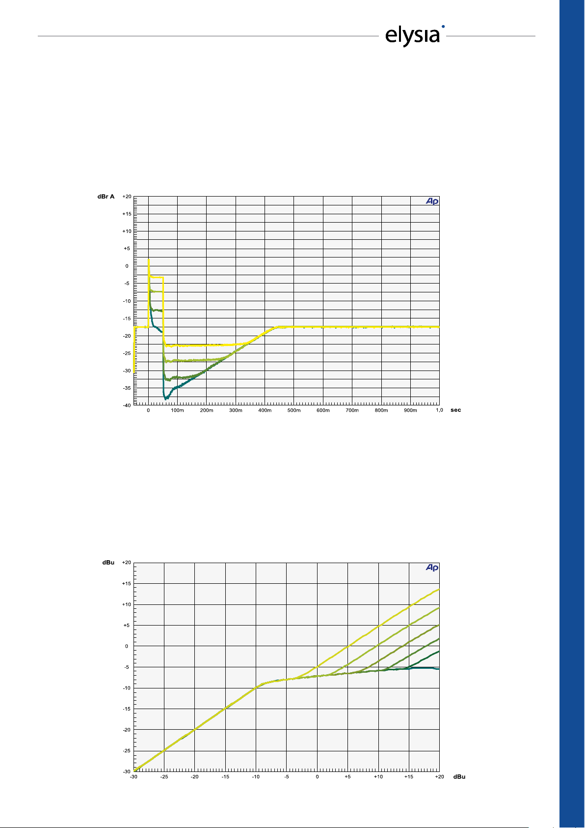
GR Limit Envelope
Here, a burst signal is used to demonstrate the eect of the Gain Reduction Limiter. While the
lowest curve represents the maximum amount of gain reduction in this example, the other curves
show the reduction that is inuenced by dierent settings of the now activated limiter. The eect
of this function can also be observed with a look at the gain reduction LED meter: The displayed
value never exceeds the limit which is set with the GR Limit controller – no matter, how high the
input level might become.
GR Limit Characteristic
Finally, a sine wave which increases in level is used in another angle of specifying the eect of the
Gain Reduction Limiter. The lowest curve shows a compressed signal with a high ratio and without
the limiter. The other curves reveal how the output level starts to rise again after the compression
phase, because the maximum amount of gain reduction which is set with the GR Limit controller
has already been utilized completely. This eect can be used to achieve compression within a selective range of level exclusively, whereby loud signals can still keep their original dynamics.
23
REFERENCE – GR Limit Envelope & Characteristic
Page 24

APPENDIX
Technical Data
Frequency response: <10 Hz – 33 kHz (-3.0 dB)
THD+N @ 0 dBu, 20 Hz - 22 kHz: 0.04 %
THD+N @ +10 dBu, 20 Hz - 22 kHz: 0.33 %
Noise oor, 20 Hz - 20 kHz (A-weighted): -84.0 dBu
Dynamic range, 20 Hz - 22 kHz: 109 dB
Maximum input level: +25 dBu
Maximum output level: +27 dBu
Input impedance: 10 kOhm
Output impedance: 68 Ohm
Input pin assignment: 1. Ground
2. Positive
3. Negative
Output pin assignment: 1. Ground
2. Positive
3. With 68 Ohm to Ground
Power consumption: 50 W max
Fuse type: 230 VAC 0.8 A Slo-Blo
115 VAC 1.6 A Slo-Blo
Dimensions (W x H x D): 483 mm x 89 mm x 377 mm
19 “ x 3.5” (2 U) x 14.8”
Weight: 8 kg / 18 lb
Level Problems
No Signal
This problem can eventually be caused by balanced wiring. If the signal almost drops completely when the
mpressor is activated, a pin of the XLR connector at the input is probably not connected. As the input stages
behave like transformers do, both pins have to be connected. The classic example for this problem is a balanced XLR cable that is connected to an unbalanced output which only uses ground and pin 2 – connecting
pin 3 to ground should solve the trouble.
Level Jump
In some audio processors the output stage is designed in a way that the level will always stay the same – no
matter if they are connected with a balanced or an unbalanced cable. If pin 3 is connected to ground, for example, the level at pin 2 will automatically become twice as loud as before. This kind of output stage is usually unproblematic. But there are also stages which cannot compensate that. Then the level at pin 2 stays as
it is, even if pin 3 is connected to ground. If the mpressor is placed between a device with that kind of output
stage and a device with unbalanced inputs with pin 3 connected to ground, it is possible that the level will
jump up by 6 dB when the compressor is activated. As a general rule, balanced input stages are always the
best choice. In case they are not available, the rst attempt to solve this problem should be to disconnect
pin 3 at the XLR inputs of the mpressor and then connect it to ground. This generates an unbalanced signal
that should not shift levels anymore.
24
APPENDIX – Technical Data & Level Problems
Page 25

Warranty
Conditions and limitations
The mpressor is covered by a limited warranty for a period of 2 years against defects in parts and labor from
the date of purchase. Natural wear is not covered by this warranty. elysia will remedy problems caused by
material or workmanship either by repair or replacement to restore the product to full performance without
charge for parts and labor. Repairs or replacements will not extend the warranty period.
The warranty is given to the original purchaser only and is not transferable. elysia will only give warranty on
products purchased through authorized elysia dealers. The warranty will only be valid in the country of the
original purchase unless otherwise pre-authorized by elysia.
All warranties become void when the product has been damaged by misuse, accident, neglect, modication, tampering or unauthorized alteration by anyone other than elysia authorized service personnel.
The warrantor assumes no liability for property damage or any other incidental or consequential damage
whatsoever which may result from failure of this product. Any and all warrantees of merchantability and tness implied by law are limited to the duration of the expressed warranty.
This warranty gives you specic legal rights and you may also have other rights which vary from state to
state. Some of the above limitations may not apply to you.
Registration and return
To conrm your warranty please register your elysia product shortly after purchase. The easiest and fastest
way is to use the online form you will nd in the service section of our website www.elysia.com. If you cannot
or do not want to use this option, please contact us via the address you will nd at the end of this warranty
statement. You will be provided with registration documents suitable for fax or mail use free of charge.
In case you notice any defect, please contact elysia for technical support directly. You can nd the correspondent contact data at the end of this warranty statement. You will receive a return authorization which
enables you to send your product to the elysia factory where it will be repaired and then sent back to you.
Packaging and shipping
All returns to the factory must be in the original packaging, accompanied by the return authorization, and
must be shipped via insured freight at the customer‘s own expense. A new original packaging can be ordered from elysia. The customer will be charged for new factory original packaging if he fails to ship the
product in the original factory packaging.
In case that a product must be returned to the factory from a country outside Germany, the customer shall
adhere to specic shipping, customs, and commercial invoicing instructions given with the return authorization as elysia will not be responsible for transportation costs or customs fees related to any importation or
re-exportation charges whatsoever.
After repair, the product will then be returned to the customer via prepaid, insured freight, method and
carrier to be determined by elysia. elysia will not pay for express or overnight freight service or pay for shipments to locations outside Germany. All damages caused by transport are not covered by this warranty.
Contact data
For technical support please contact:
elysia GmbH
Am Panneschopp 18
41334 Nettetal
Germany
info@elysia.com
Version 1.2
Printed in Germany
APPENDIX – Warranty
25
Page 26

-0,3
5,0 10
Ratio
Release
85 150
50
Attack
17 21
13
Threshold
-5 -8
0
-2,0
-1,0
-3,0
-4,0
1:X
1,2
1,3
2,0
1,6
380
930
600
1k2
ms
5
7
26
12
70
140
100
150
ms
0,01
1,0
8,0
5,0
SC Extern Auto Fast Anti Log
-13
-17
-15
-18
dB
16
5
14
9
Gain
4,0 6,0
3,0
GR Limit
11 9
13
EQ Freq
200 260
90
EQ Gain
1,0 1,0
2,0
13
10
17
20
dB
0
0,5
2,0
1,0
5
3
1,5
0
dB
21
19
15
17
450
1k3
700
2k2
Hz
26
28
52
36
On x10 On
3,0
4,5
6,0
Hi
dB
Lo
6,0
3,0
4,5
Right
-0,3
5,0 10
Ratio
Release
85 150
50
Attack
17 21
13
Threshold
-5 -8
0
Link
Left
13
10
-2,0
-1,0
-3,0
-4,0
4,0 6,0
1:X
1,2
1,3
2,0
1,6
380
930
600
1k2
ms
11 9
5
7
26
12
70
140
100
150
ms
200 260
0,01
1,0
8,0
5,0
SC Extern Auto Fast Anti Log
-13
-17
-15
-18
dB
1,0 1,0
16
5
14
9
Gain
3,0
2,0
5
GR Limit
13
15
450
EQ Freq
90
52
3,0
EQ Gain
2,0
3,0
17
20
dB
0
0,5
1,0
3
1,5
0
dB
21
19
17
1k3
700
2k2
Hz
26
28
36
On x10 On
4,5
6,0
Hi
dB
Lo
6,0
4,5
26
Download the PDF at www.elysia.com
Project . . . . . . . . . . . . . . . . . . . . . . . . . . . . . . . . . . . . . . . . . . . . . . . . . . . . . . . . . . . . . . . . . . . . . . . . . . . . . . . . . . .
Song . . . . . . . . . . . . . . . . . . . . . . . . . . . . . . . . . . . . . . . . . . . . . . . . . . . . . . . . . . . . . . . . . . . . . . . . . . . . . . . . . . . .
Engineer . . . . . . . . . . . . . . . . . . . . . . . . . . . . . . . . . . . . . . . . . . . . . . . . . . . . . . . . . . . . . . . . . . . . . . . . . . . . . . . . .
Date . . . . . . . . . . . . . . . . . . . . . . . . . . . . . . . . . . . . . . . . . . . . . . . . . . . . . . . . . . . . . . . . . . . . . . . . . . . . . . . . . . . .
Left Channel Track . . . . . . . . . . . . . . . . . . . . . . . . . . . . . . . . . . . . . . . . . . . . . . . . . . . . . . . . . . . . . . . . . . . . . . . . . . .
Right Channel Track . . . . . . . . . . . . . . . . . . . . . . . . . . . . . . . . . . . . . . . . . . . . . . . . . . . . . . . . . . . . . . . . . . . . . . . . . .
Notes . . . . . . . . . . . . . . . . . . . . . . . . . . . . . . . . . . . . . . . . . . . . . . . . . . . . . . . . . . . . . . . . . . . . . . . . . . . . . . . . . . .
. . . . . . . . . . . . . . . . . . . . . . . . . . . . . . . . . . . . . . . . . . . . . . . . . . . . . . . . . . . . . . . . . . . . . . . . . . . . . . . . . . . . . . . .
. . . . . . . . . . . . . . . . . . . . . . . . . . . . . . . . . . . . . . . . . . . . . . . . . . . . . . . . . . . . . . . . . . . . . . . . . . . . . . . . . . . . . . . .
Page 27

 Loading...