

Page 1
USER MANUAL
MANUALE D’USO
BENUTZER HANDBUCH
MANUEL D'UTILISATION
Ely
Q
Competition
Page 2

EN DE FRIT
Introduction
Congratulation for your choice! Our Vision 50 is
designed for modelers who love building and flying an
highest quality model helicopter. The Vision 50 requires
a short time for assembly and easy maintenance using
standard hobby tools. This model, thanks to high
performance and top flight features, is ideal for both
beginner and expert pilots.
Warning
The Vision 50 is a precision machine requiring proper
assembly and setup in order to avoid serious body
injury. The manufacturer and distributors assume no
liability for damages that could occur from the
assembly or misuse of this product. It is under owner
responsibility to operate the helicopter in a safe mode,
so we recommend seeking help and guidance from
other accomplished model helicopter pilots to ensure
quick and successful learning.
Read carefully this manual first
Keep the model KIT parts away from children.
Once finished assembling, the model is ready for
testing; it is highly recommended that beginners seek
the help of experienced RC helicopters pilots, or
contact a Flying Club in order to get the necessar y
knowledge on how to use the model.
If you are in doubt of your ability or on the current safety
rules, we strongly recommend you to ask f or
assistance from experienced radio controlled
helicopter modelers or join your local model flying club
to gain the required knowledge and skill.
ElyQ does not assume the liability for the use and / or
misuse of the model.
This model is not a toy.
ElyQ reserves the right to make any changes
considered necessary without prior notice and shall not
be liable for technical or editorial errors or omissions
contained herein. For updates or further info, please
visit our site www.elyq.com
Introduzione
Congratulazioni per aver scelto il nostro modello Vision
50, un elicottero studiato con l’obbiettivo di rendere
estremamente semplice il montaggio e soprattutto la
manutenzione. Questa meccanica, grazie alle elevate
prestazioni e caratteris tiche di volo che la distinguono,
è ideale sia per i principianti che per i più esperti.
Avvertenze
L’elicottero Vision 50 è un apparecchio di precisione
che richiede un corretto assemblaggio e settaggio per
evitare incidenti o conseguenze che potrebbero
risultare dannose. E’ responsabilità del possessore
utilizzare in maniera corretta e sicura il modello, per
evitare danni a cose o persone, a causa di mancanza di
sicurezza o di uso scorretto.
Leggere prima questo manuale di montaggio.
Non lasciate che i bambini utilizzino il materiale incluso
nel KIT senza la supervisione di un adulto.
Una volta completato il montaggio ed installato con
cura i componenti necessari, il vostro modello è pronto
per il collaudo. Se non avete ancora un sufficiente
controllo nel volo, raccomandiamo caldamente
l’assistenza di personale dotato di esperienza nel
telecomandare gli elicotteri o di rivolgersi al Vs. “Flying
Club” per acquisire la necessaria conoscenza e utilizzo
del prodotto.
Chiedete informazioni, tramite per sonale dotato di
esperienza, in riferimento alle norme di sicurezza
durante le prove e i voli. Anche in questo caso
suggeriamo di rivolgersi al Vs. più vicino “Flying Club”
per acquisire le norme sulla sicurezza relative agli
elicotteri R/C.
Se è il Vision 50 è il vostro primo elicotter o R/C che
assemblate raccomandiamo caldamente di farvi
assistere da un pilota esper to per la messa a punto e
per le prime istruzioni di volo.
ElyQ non si assume nessuna responsabilità relativa
all’uso del prodotto.
Questo modello non è un giocattolo.
ElyQ declina ogni responsabilità per eventuali errori
e/o imprecisioni nelle informazioni riportate e si
riserva il diritto di apportare ogni modifica ritenuta
necessaria, senza alcun preavviso.
Visitate il nostro sito per eventuali aggiornamenti e/o
ulteriori informazioni: www.elyq.com
Einleitung
Wir gratulieren Ihnen zu der Wahl unseres
Hubschraubers Vision 50. Dieser Hubschrauber wurde
mit dem Ziel entworfen, die Montage und vor allem die
Wartung extrem leicht zu gestalten. Dieses Modell eignet
sich dank seiner Leistungen und optimalen
Flugeigenschaften ideal für Anfänger und für Exper ten.
Hinweise
Der Hubschrauber Vision 50 ist ein Präzisionsgerät, das
eine korrekte Montage und Einstellung verlangt, um
Unfälle oder Schaden bringende Folgen zu vermeiden. Es
liegt in der Verantwortung des Benutzers, das Modell
korrekt und sicher zu benutzen, um Schäden an
Gegenständen und Personen zu vermeiden, die auf Grund
von fehlender Sicherheit und nicht korrektem Gebrauch
entstehen können.
Lesen Sie zuerst dieses Montagehandbuch.
Lassen Sie Kinder nicht das Material, das in dem Bausatz
enthalten ist, benutzen.
Wenn die Montage abgeschlossen ist und die notwendigen
Komponenten installiert sind, ist Ihr Modell bereit für die
Endkontrolle; wenn Sie noch keine ausreichenden
Erfahrungen mit dem Umgang eines Modellhubschrau
bers haben, empfehlen wir Ihnen die Unterstützung durch
erfahrene Piloten. Wenden Sie sich an Ihren nächstgele
genen Modellflugverein, um die notwendigen Kenntnisse zu
erwerben und das Fliegen zu lernen.
Informieren Sie sich auch über die Sicherheitsvorschrif ten
während der Tests und des Flugs. Auch in diesem Fall
empfehlen wir Ihnen, sich an den nächsten Modellflugve
rein zu wenden, um die Sicherheitsnormen für die Hub
schrauber R/C zu bekommen.
Für ferngesteuert e Flug modelle besteht die generelle
Pflicht einer Modellflug-Haftpflichtver sicherung. Eine
private Haftpflichtver siche rung ist nicht ausreichend.
ElyQ übernimmt keinerlei Verantwortung bezüglich des
Gebrauch des Produkts.
Dieses Modell ist kein Spielzeug.
ElyQ entzieht sich jeglicher Verantwortung für eventuelle
Fehler und/oder Abweichungen bei den angegebenen
Informationen und behält sich außerdem das Recht vor,
jede für notwendig gehaltene Veränderung ohne
Vorankündigung vorzunehmen.
Besuchen Sie unsere Webseite für eventuelle
Aktualisierungen und weitere Informationen:
www.elyq.com
Introduction
Nous tenons à vous féliciter d'avoir choisi notre
hélicoptère Vision 50, un hélicoptère étudié dans
l'objectif de rendre extrêmement simple le montage et
surtout l'entretien. Ce modèle, grâce aux prestations et
aux caractéristiques élevées de vol, est idéal pour les
débutants et pour les personnes les plus expérimentées.
Avertissements
L'hélicoptère Vision 50 est un appareil de précision qui
demande un assemblage et un réglage correct pour
éviter tout accident ou des conséquences qui pourraient
s'avérer nuisibles. Le propriétaire de l'hélicoptère est
responsable de son utilisation correcte et sûre, pour
éviter des dommages aux choses ou aux personnes, à
cause de manque de sécurité ou d'usage incorrect.
Lire auparavant ce manuel de montage.
Ne pas laisser le matériel inclus dans le KIT à la portée
des enfants.
Une fois le montage terminé et les composants
nécessaires installés, votre modèle es t prêt pour l'essai;
mais vous n'avez pas encore un contrôle suffisant du vol,
par conséquent nous vous conseillons vivement de
recourir à l'assistance de personnel expériment é dans la
télécommande des hélicoptères ou de vous adresser à
votre “Flying Club” pour acquérir les connaissances
nécessaires pour utiliser ce produit.
Demandez des informations, par l'intermédiaire du
personnel expérimenté, en référence aux nor mes de
sécurité pendant les essais et les vols. Dans ce cas
également nous vous conseillons de vous adresser au
“Flying Club” le plus proche de votre domicile pour
prendre connaissance des normes sur la sécurité
relatives aux hélicoptères R/C.
S'il s'agit du premier hélicoptère R/C que vous réalisez.
nous vous conseillons vivement de vous faire aider par un
pilote expérimenté pour la mise au point et pour les
premières instructions de vol.
ElyQ ne se peut être tenue responsable quant à
l'utilisation du produit.
Ce modèle n'est pas un jouet.
ElyQ décline toute responsabilité en cas d'éventuelles
erreurs et/ou imprécisions dans les informations
reportées et se réserve le droit d'apporter toute
modification jugée nécessaire, sans aucun préavis.
Visitez notre site pour des mises à jour éventuelles
et/ou ultérieures informations: www.elyq.com
Ely
Q
Introduction / Introduzione / Einführung / Introduction
Vision 50 - Competition / Italy 13-05-2009
Page 3
Ely
Q
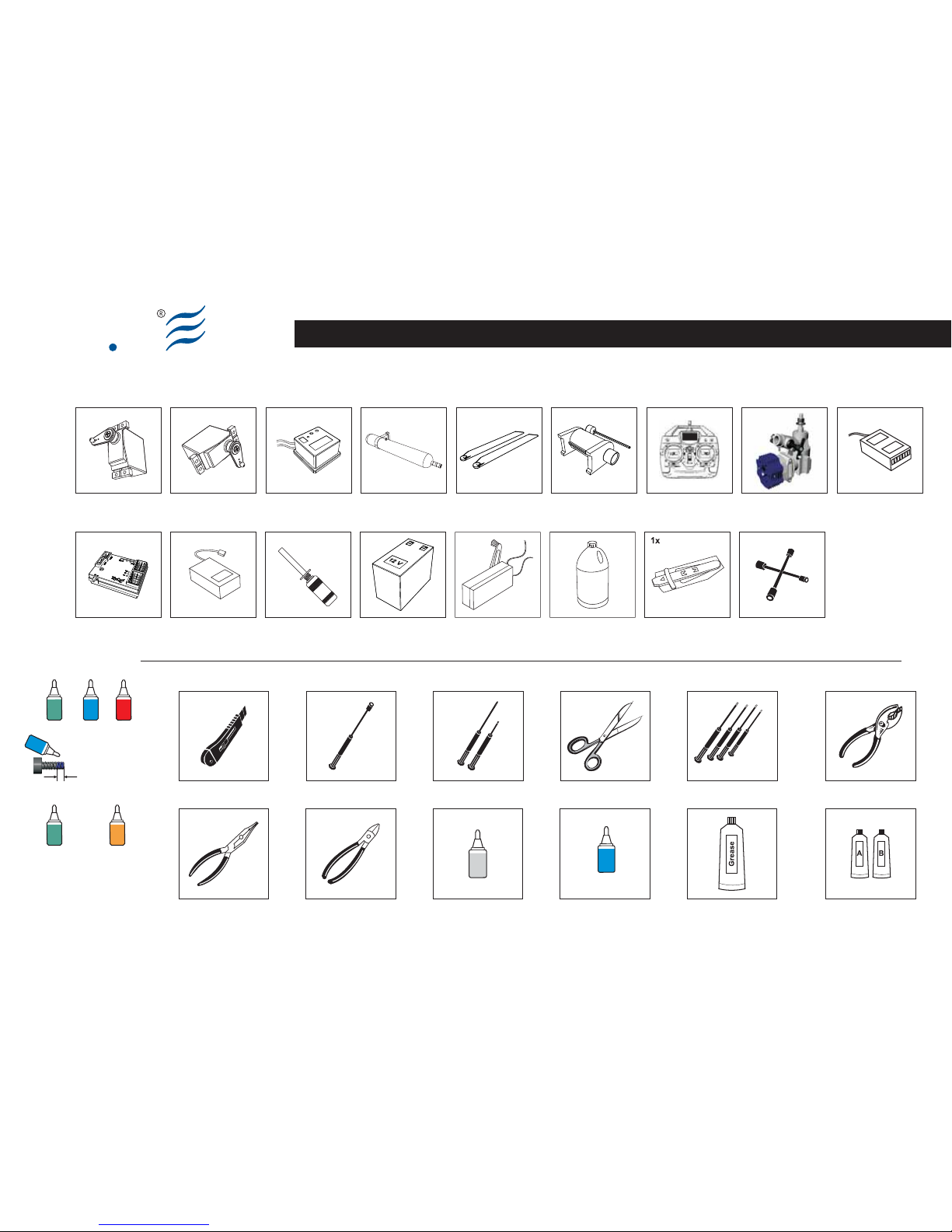
Equipment required for Assembly
ScissorsScrew DriversHobby cutter knife Socket Drivers
5.5
7
8
10
Cutting Pliers
Epoxy
Grease
Ball Link Pliers
PliersHex Wrench
1.5
2
2.5
3
Cyano Acrylate
Cyano
acrylate
Blue Lockite
Blue
Locktite
243
Standard Servo
4x
600/620 Blades
1x set
ElyQ - Voltage Regulator
1x
Recommended
Tools required for assembly - Attrezzi richiesti per l’assemblaggio - Benötigte Werkzeuge für die Montage - Outils nécessaires pour l'assemblage
Heli Engine (.50)
1x
Specific Tail Servo
1x
Muffler (.50)
1x
Engine Starter
1x
Receiver (6ch or more)
1x
Transmitter 6ch or more
1x
Helicopter System
Head Lock Gyro
1x
7.4V-1.5A/2A Lipo Battery
1x
12V Battery
1x
Glow Starter
1x
Fuel Pump
1x
Fuel Glow Plug Wrench
1x
Pitch Gauge
Blue
Locktite
243
Red
Locktite
222
Green
Locktite
680
Green
Locktite
638
641
Yellow
Locktite
Glue width: approx. 1mm
Locktite
Retention of bearings onto
shafts and into housings
Vision 50 - Competition / Italy 13-05-2009
Page 4

Ely
Q
S001-1
Fuel Tank Assy
BAG EQ3000
EN DE FRIT
(Bag EQ3000)
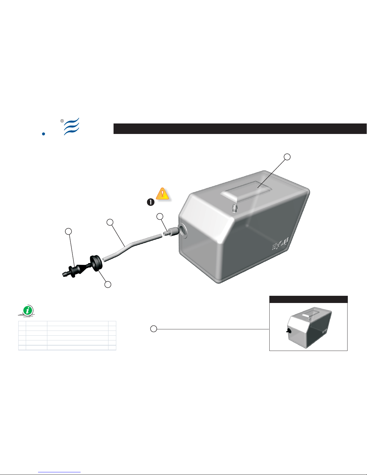
Fuel Tank Assembly
The fuel tank comes assembled from the
factory.
The Silicon fuel clunk tube (4), plugged
into the Fuel Tank (3), has a top
quality feature and it is designed in order
to work with very high nitromethane
percentage. In spite of this
characteristic, we recommend to make
periodic controls to avoid possible
anomalies. If the control should highlight
deterioration, we suggest a replacement,
otherwise it can break off.
(Bag EQ3000)
Fuel Tank Assembly
Questa parte viene fornita già
assemblata.
Il Silicone fuel clunk tubing (4) inserito
nel Fuel Tank (3) è di ottima qualità ed
il materiale è stato selezionato per
operare con percentuali di nitrometano
molto alte. Ciò nonostante è consigliabile,
al fine di evitare possibili anomalie, di
effettuare controlli periodici. Qualora si
dovesse evidenziare un deterioramento
se ne suggerisce la sostituzione.
(Bag EQ3000)
Fuel Tank Assembly
Dieses Teil wird bereits montiert
geliefert.
Der Silikonschlauch (4), der in den
Kraftstofftank (3) eingesetzt wird, hat
eine optimale Qualität, damit auch sehr
hoch nitromethanhaltiger Sprit benutzt
werden kann. Dennoch ist es ratsam,
eine regelmäßige Kontrolle durchzufüh
ren, um mögliche Schäden am Schlauch
und am Tank zu vermeiden. Falls die Kon
trolle eine Verschlechterung aufweisen
sollte, ist eine sofortige Erneuerung not
wendig.
(Bag EQ3000)
Fuel Tank Assembly
Cet ensemble est fourni déjà assemblé.
Le Silicone fuel clunk tubesng (4)
inséré dans le Fuel Tank (3) est
d'excellente qualité et le matériel a été
sélectionné pour opérer avec des
pourcentages de nitrométhane très
élevés. Cependant il est conseillé, afin
d'éviter de possibles anomalies,
d'effectuer un contrôle périodique. Au
cas où le contrôle devait révéler une
détérioration, il est conseillé de procéder
au remplacement.
Vision 50 - Competition / Italy 13-05-2009
Page 5
Preview
Ely
Q
Fuel Tank Assy
BAG EQ3000
6
5
4
3
2
1
S001-2 Vision 50 - Competition / Italy 13-05-2009
1 8003100A Fuel tank stopper 1
2 8004400A Fuel t ank nipple 1
3 8010900A Fuel t ank (V50c ) 1
4 8011000A Silic on fuel tube L=80mm d2.5, D6 1
5 8103600A Fuel Clunk 1
6 8402000A Fuel Tank As sy
Page 6

Ely
Q
S002-1
Guide Pulley Assy
BAG EQ3001
EN DE FRIT
(Bag EQ3001)
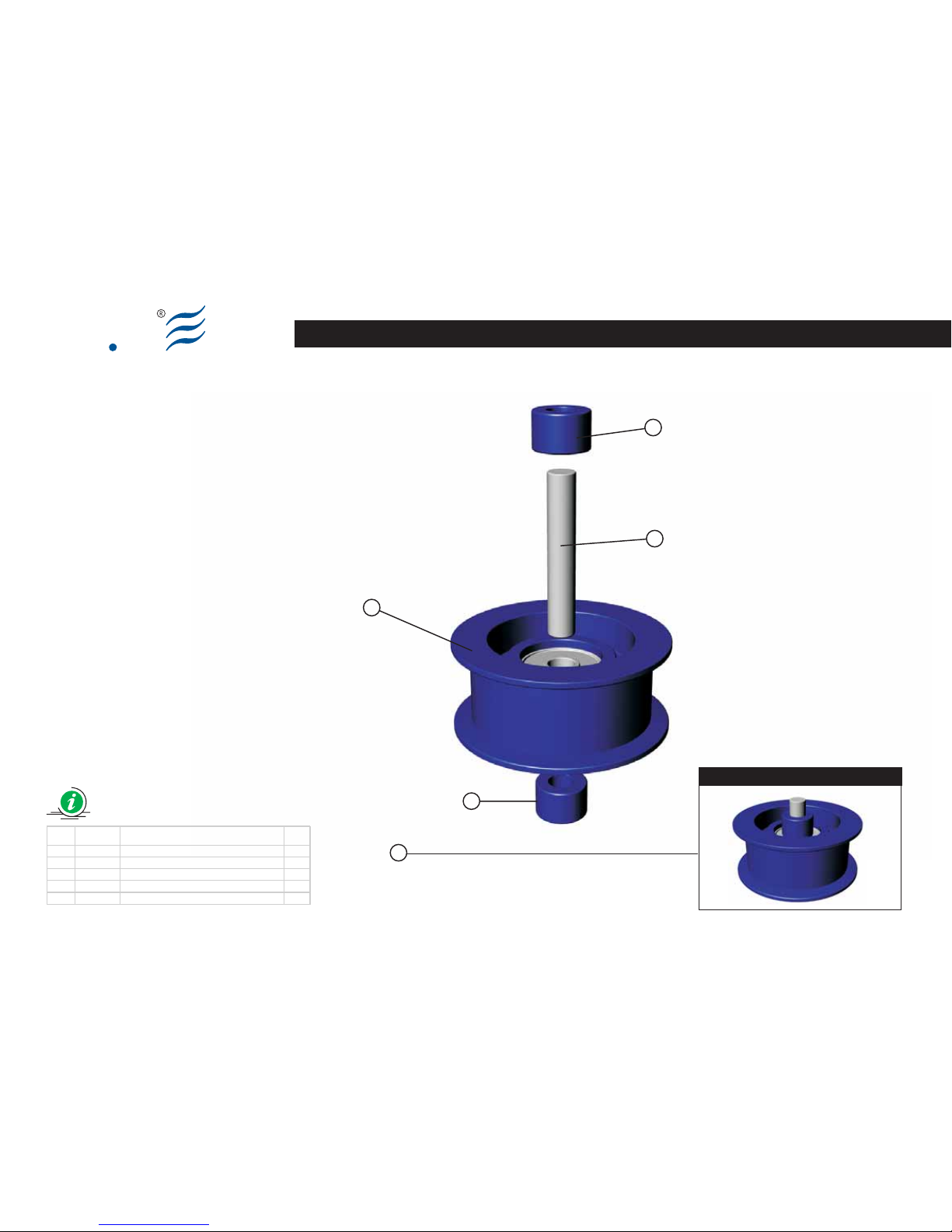
Guide Pulley Assy
Insert the PIN (3) in the Guide Pulley (2)
bearing and locking them symmetrically
using the Pulley collar (1).
(Bag EQ3001)
Guide Pulley Assy
Inserire il PIN (3) nel relativo cuscinetto
situato nella Guide Pulley (2) e fermarlo,
simmetricamente, con i Pulley collar (1).
(Bag EQ3001)
Guide Pulley Assy
Setzen Sie den PIN (3) in das Lager des
Rads Guide Pulley (2) ein und befestigen
Sie es symmetrisch mit den Pulley Collar
(1).
(Bag EQ3001)
Guide Pulley Assy
Introduire le PIN (3) dans le coussinet
relatif à la roue Guide Pulley (2) et
l'arrêter, symétriquement, avec les Pulley
collar (1).
Vision 50 - Competition / Italy 13-05-2009
Page 7
Preview
4
3
2
1
1
Guide Pulley Assy
Ely
Q
Item Code Description Q.ty
1 8004000A Pulley coll ar 2
2 8004100A
Guide pulley with bearing d3, D10, W4 1
3 8103800A Pin Ø 3x 17.75 1
4 8400800A Guide pulley ass y
S002-2
BAG EQ3001
Vision 50 - Competition / Italy 13-05-2009
Page 8

Ely
Q
EN DE FRIT
(Bag EQ3009)
Main Frame Assembly (Part 01)
Make up the assy according to the
drawing.
The fuel tank and the Guide pulley have
already been assembled.
Each screw identified by the “Locktite”
symbol, must be impregnated with a
small drop of medium seal Locktite (blue).
The screws M2x4 (29) must not be
over tighten, because they must
ensure a good seal without over
fastening.
(Bag EQ3009)
Main Frame Assembly (Part 01)
Eseguire il montaggio secondo lo
schema.
Il serbatoio e le ruote guida cinghia sono
state già assemblate precedentemente.
Ogni vite, dove è riportato il simbolo
“Locktite”, deve essere
preventivamente impregnata di Locktite a
tenuta media (blu).
Le viti M2x4 (29) non devono essere
serrate in maniera eccessiva. Le
stesse devono assicurare una buona
tenuta ma senza eccedere nel serraggio.
(Bag EQ3009)
Main Frame Assembly (Part 01)
Führen Sie die Montage nach dem
Schema aus.
Der Tank und die Riemenführungsräder
wurden schon vorher montiert.
Wo das Symbol “Locktite” angebracht
ist, muss jede Komponente mit Locktite
mittelfest (blau) gesichert werden.
Die selbstschneidenden Screw M2x4
(29) müssen einen guten Halt
garantieren, ohne diese zu überdrehen.
(Bag EQ3009)
Main Frame Assembly (Part 01)
Exécuter le montage selon le schéma.
Le réservoir et les roues de guidage
courroie ont été déjà assemblés au
préalable .
Chaque vis, où est reporté le symbole
“Locktite”, doit être au préalable
imprégnée de Locktite à tenue moyenne
(bleue).
Les vis M2x4 (29) ne doivent être
excessivement serrées. Celles-ci
doivent assurer une bonne tenue mais
sans excéder dans le serrage.
Main Frame Assembly (Part 01)
BAG EQ3009
S003-1 Vision 50 - Competition / Italy 13-05-2009
Page 9
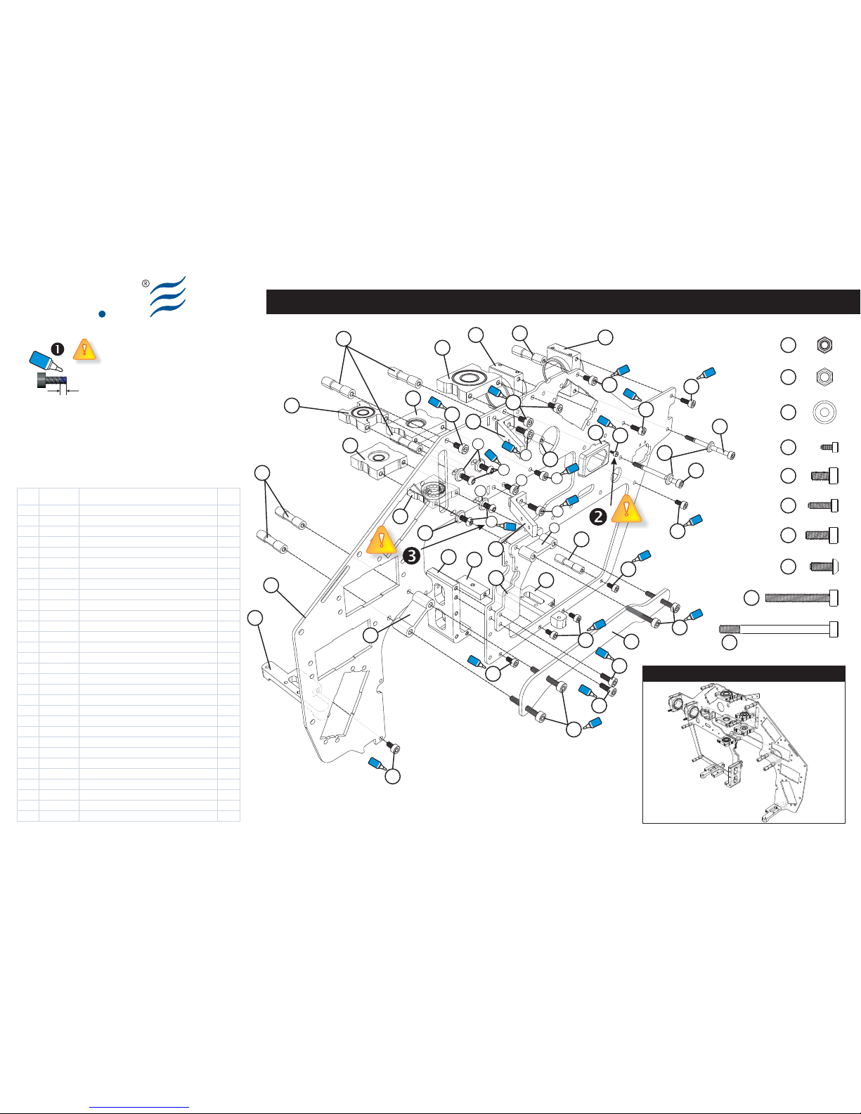
Main Frame Assembly (Part 1.00)
Ely
Q
S003-2
BAG EQ3009
Item Code Description Q.ty
1 8109300B Landi ng Ski d Brace Mount (V50c ) 2
2 8108000A Tail P ulley Housing (V50c ) 2
3 8109400A Tail B oom Clamp (V 50c) 2
4 8109100A F rame Spac er Medium (V50c ) 2
5 8110600A F rame Spac er Smaller (V 50c) 2
6 8108100A B earing Support d10,D22,W 6 (V50c) 2
7 8108900A 26 m m spac er (V50c) 8
8 8108400A M otor Mount Center (V50c) 1
9
10 8110300A Bott om Reinforcement Bloc k 1
11 8108200A Bearing d8, D19,W6 S upport (V50c ) 1
12 8108300A Bearing d6, D15,W5 S upport (V50c ) 1
13 8109000A Bearing d9, D17,W4 S upport (V50c ) 1
14 8108600A Servo Mount Side (V 50c) 4
15 8200400A Lock Nut M3 2
16 8010600B Carbon Support Fram e (V50c) 2
17 8009700A Carbon Breakout Tab (V50c) 2
18 8009500A Carbon Side Pl ate (V50c ) 2
19 8009600A Carbon Bott om Plat e (V50c) 1
20 8009800A Gyro Mount CF (V50c) 1
21 8009400B Main Fram e CF (V50c) 2
22 8205200A Sock et S crew M3x6 29
23 8204700A Sock et S crew M2.5x 8 6
24 8201200A Flat W asher d3, D8,W 1.5 12
25 8200800A Lock Nut M2.5 2
26 8205400A Sock et S crew M3x22 8
27 8201900A Sock et B utton Head Screw M3x8 8
28 8205300A Sock et S crew M3x38 (30+ 8) 2
29 8205100A Sock et S crew M2x4 2
30 8201800A Sock et S crew M3x8 12
Vision 50 - Competition / Italy 13-05-2009
7
1
3
3
1
7
6
6
7
7
5
8
4
7
2
22
21
22
22
26
26
18
16
10
13
12
11
14
14
24
24
29
28
28
30
30
30
30
22
22
22
22
22
24
24
27
30
22
22
30
27
Preview (V50 Competition)
Glue width: approx. 1mm
Blue
Locktite
Blue
Locktite
Blue
Locktite
Blue
Locktite
Blue
Locktite
Blue
Locktite
Blue
Locktite
Blue
Locktite
Blue
Locktite
Blue
Locktite
Blue
Locktite
Blue
Locktite
Blue
Locktite
Blue
Locktite
Blue
Locktite
Blue
Locktite
Blue
Locktite
Blue
Locktite
Blue
Locktite
Blue
Locktite
Blue
Locktite
Socket screw M3x38 (x2)
Socket screw M3x22 (x8)
Socket screw M3x8 (x12)
Socket screw M3x6 (x29)
Socket screw M2x4 (x2)
Lock Nut M2.5 (x2)
Lock Nut M3 (x2)
Washer d3,D8,W1.5 (x12)
Socket screw M2.5x8 (x6)
Socket B.H. screw M3x8 (x8)
22
23
30
27
26
28
29
24
15
25
Page 10
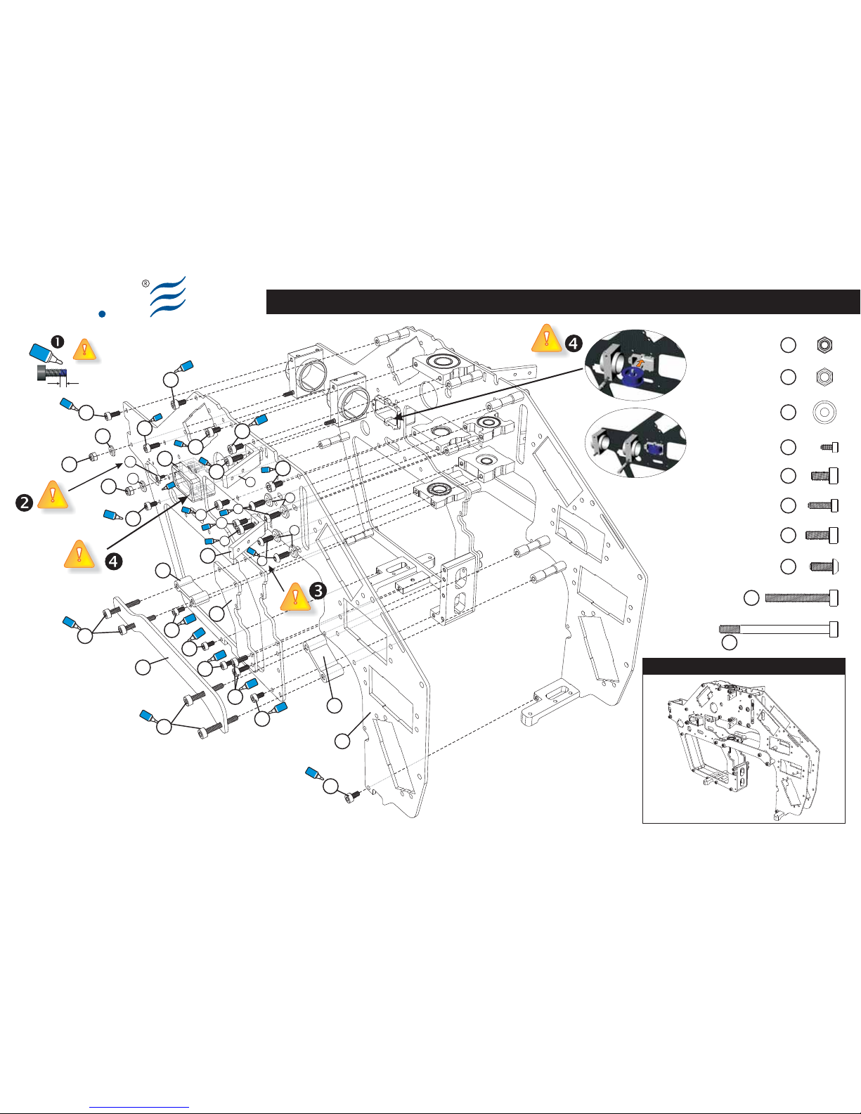
Main Frame Assembly (Part 1.01)
Ely
Q
S003-3
BAG EQ3009
Vision 50 - Competition / Italy 13-05-2009
Preview (V50 Competition)
30
30
30
30
22
22
16
15
15
22
26
26
22
22
18
22
22
21
24
24
29
22
22
22
27
14
24
24
27
30
22
14
22
4
5
Glue width: approx. 1mm
Blue
Locktite
2
Blue
Locktite
Blue
Locktite
Blue
Locktite
Blue
Locktite
Blue
Locktite
Blue
Locktite
Blue
Locktite
Blue
Locktite
Blue
Locktite
Blue
Locktite
Blue
Locktite
Blue
Locktite
Blue
Locktite
Blue
Locktite
Blue
Locktite
Blue
Locktite
Blue
Locktite
Blue
Locktite
Blue
Locktite
Blue
Locktite
Blue
Locktite
Blue
Locktite
Socket screw M3x38 (x2)
Socket screw M3x22 (x8)
Socket screw M3x8 (x12)
Socket screw M3x6 (x29)
Socket screw M2x4 (x2)
Lock Nut M2.5 (x2)
Lock Nut M3 (x2)
Washer d3,D8,W1.5 (x12)
Socket screw M2.5x8 (x6)
Socket B.H. screw M3x8 (x8)
22
23
30
27
26
28
29
24
15
25
Page 11
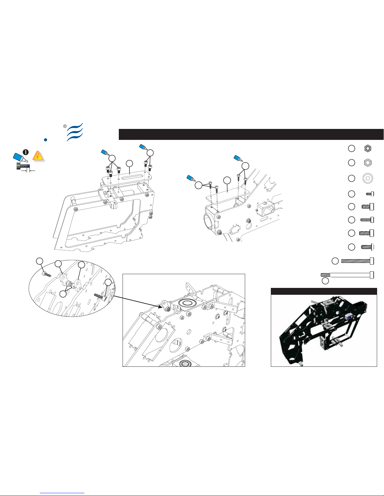
Main Frame Assembly (Part 1.02)
Ely
Q
BAG EQ3009
Glue width: approx. 1mm
Blue
Locktite
S003-4 Vision 50 - Competition / Italy 13-05-2009
22
19
22
Blue
Locktite
Blue
Locktite
Socket screw M3x38 (x2)
Socket screw M3x22 (x8)
Socket screw M3x8 (x12)
Socket screw M3x6 (x29)
Socket screw M2x4 (x2)
Lock Nut M2.5 (x2)
Lock Nut M3 (x2)
Washer d3,D8,W1.5 (x12)
Socket screw M2.5x8 (x6)
Socket B.H. screw M3x8 (x8)
22
23
30
27
26
28
29
24
15
25
23
23
20
Blue
Locktite
Blue
Locktite
Preview (V50 Competition)
23
25
17
23
17
Page 12

Ely
Q
S005-1
EN DE FRIT
(Bag EQ3003)
Clutch Bell Assy
Make up the assy according to the drawing.
The Clutch Bell (1), the Liner (6) and the
Bearing (5) come assembled from the
factory. However, we suggest making a quality
check.
Don't over tighten the Drive Gear Pinion (3)
nut.
Add small drop of medium seal locktite
(blue) between the Drive Gear Pinion and
the corresponding nut (3). Repeat the same
operation between the Drive Gear Pinion (3)
and the Clutch Bell (1).
The Liner (6) is not preassembled. Inside
the BAG an innovative kit is given that
enables the user to glue it quickly and
precisely. The first step is very simple: spread
epoxy glue (30 min) on the Liner (6) and on
the inner side of the Clutch Bell (1).
Wrap the Liner (6) all around the body of the
specific tool (A) and adjust it so that it can fit
inside the Clutch Bell (1). Once you have
adjusted and alined it up insert the Wedge
(B) using a clamp or a Screw/Nut (M6) and
2 washers of appropriate size. Make sure to
get the Liner (6) pressed on the side of the
Clutch Bell (1). See example picture.
Let the glue cure: needed time depends on
the sort of glue used. You may also speed up
the fastening by warming up the component,
with a small oven, up to a maximum
temperature of 45° C.
This kit may also be used for further
maintenance.
(Bag EQ3003)
Clutch Bell Assy
Eseguire il montaggio seguendo lo schema.
La Campana (1) ed il Cuscinetto (5) vengono
forniti già assemblati.
Effettuare, comunque, un controllo sulla
qualità dell'equipaggiamento.
Si suggerisce di non stringere in modo
eccessivo il dado di serraggio del cuscinetto
sul pignone principale (3).
Versare della “Lockite” media (blu) tra il
pignone principale e il relativo dado (3) di
fissaggio. Lo stesso deve essere fatto per
l’accoppiamento pignone (3) e campana (1)
Il Liner (6) non viene fornito assemblato.
All’interno del BAG viene fornito un kit che
ne permette un veloce e preciso incollaggio
dello stesso. Il principio è semplice:
distribuite con della colla epossidica (30min.)
il Liner (6) e l’interno della Campana (1).
Avvolgete il Liner (6) lungo il corpo
dell’Utensile (A) e adattatelo affinché possa
entrare all’interno della Campana (1). Una
volta adattato e allineato inserite il Cuneo (B)
e, tramite un morsetto o una Vite/Dado
(M6) e 2 rondelle di dimensioni appropriate,
serrate affinché il Liner (6) venga pressato
sulla parete della Campana (1). Vedi figura
esplicativa.
Lasciare agire la colla; il tempo necessario è
dipendente dal tipo di collante usato. Potete
agevolare l’incollaggio riscaldando il
componente, tramite un fornetto, ad una
temperatura massima di 45° gradi Celsius.
Tale kit può essere riutilizzato per successive
manutenzioni.
(Bag EQ3003)
Clutch Bell Assy
Führen Sie die Montage nach dem Schema
aus.
Die Kupplungsglocke (1), der Liner (6) und
das Lager (5) werden bereits montiert
geliefert. Bitte kontrollieren Sie dennoch die
richtige Montage.
Ziehen Sie die Schraubenmutter des
Motorritzels nicht zu stark an (3).
Geben Sie “Lockite” mittelfest (blau)
zwischen den Motorritzel und der
entsprechenden Befestigungs-Mutter (3).
Dasselbe muss bei der Verbindung Ritzel (3)
und Kupplungsglocke (1) gemacht werden.
Der Kupplungsbelag (6) ist noch nicht
eingeklebt. Verwenden Sie dafür das
beiliegende Werkzeug (A). Die Montage ist
wirklich einfach: bestreichen Sie den
Kupplungsbelag (6) und die Innenseite der
Kupplungsglocke (1) mit Epoxy-Kleber (30
Minuten). Wickeln Sie nun den
Kupplungsbelag (6) um das Werkzeug (A),
sodass Sie den Kupplungsbelag (6) in die
Kupplungsglocke (1) anbringen können.
Sobald der Kupplungsbelag (6) sauber in der
Kupplungsglocke (1) sitzt, pressen Sie mit
einer passenden Schraube und Mutter (M6)
und 2 Unterlegscheiben den Kupplungsbelag
in die Kupplungsglocke (1) (siehe Zeichnung).
Sie können außerdem den Klebevorgang
beschleunigen, indem Sie die Kupplung in
einen Ofen bei maximal 45°C geben
Sie können das Werkzeug auch für spätere
Wartungen benutzen.
(Bag EQ3003)
Clutch Bell Assy
Exécuter le montage en suivant le schéma.
La cloche de l'embrayage (1), le liner (6) et le
coussinet (5) sont fournis déjà assemblés.
Effectuer, dans tous les cas, un contrôle sur
la qualité de l'ensemble.
Ne pas exécuter un serrage excessif de
l'écrou relatif au pignon principal (3).
Verser de la “Lockite” moyenne (bleue)
entre le pignon principal et l'écrou (3) de
fixation relatif. Celui-ci doit être fait pour le
couplage pignon (3) et cloche (1)
Clutch Bell Assy
BAG EQ3003
Vision 50 - Competition / Italy 13-05-2009
Page 13
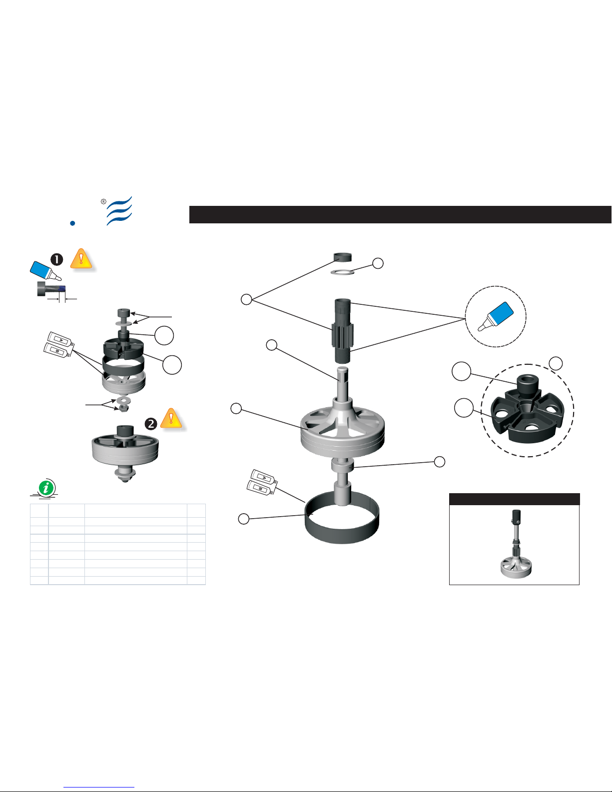
Preview
Ely
Q
Clutch Bell Assy (Part 1.00)
Blue
Locktite
Glue width: approx. 1mm
Blue
Locktite
6
5
7
4
3
1
2
Liner Mount Tool
Item Code Description Q.ty
1 8100100B Clut ch bell 1
2 8100200A S tarter s haft 1
3 8103000B Drive Gear - Pinion 11T with nut 1
4 8204100A W asher d8, D12, W 1 1
5 8601000A B earing d6,D13,W5
6 8002900B Clut ch liner 1
7 Liner Mount Tool 1
BAG EQ3003
Epoxy
Not included
Not included
A
B
Epoxy
A
B
Vision 50 - Competition / Italy 13-05-2009S005-2
Page 14
Ely
Q
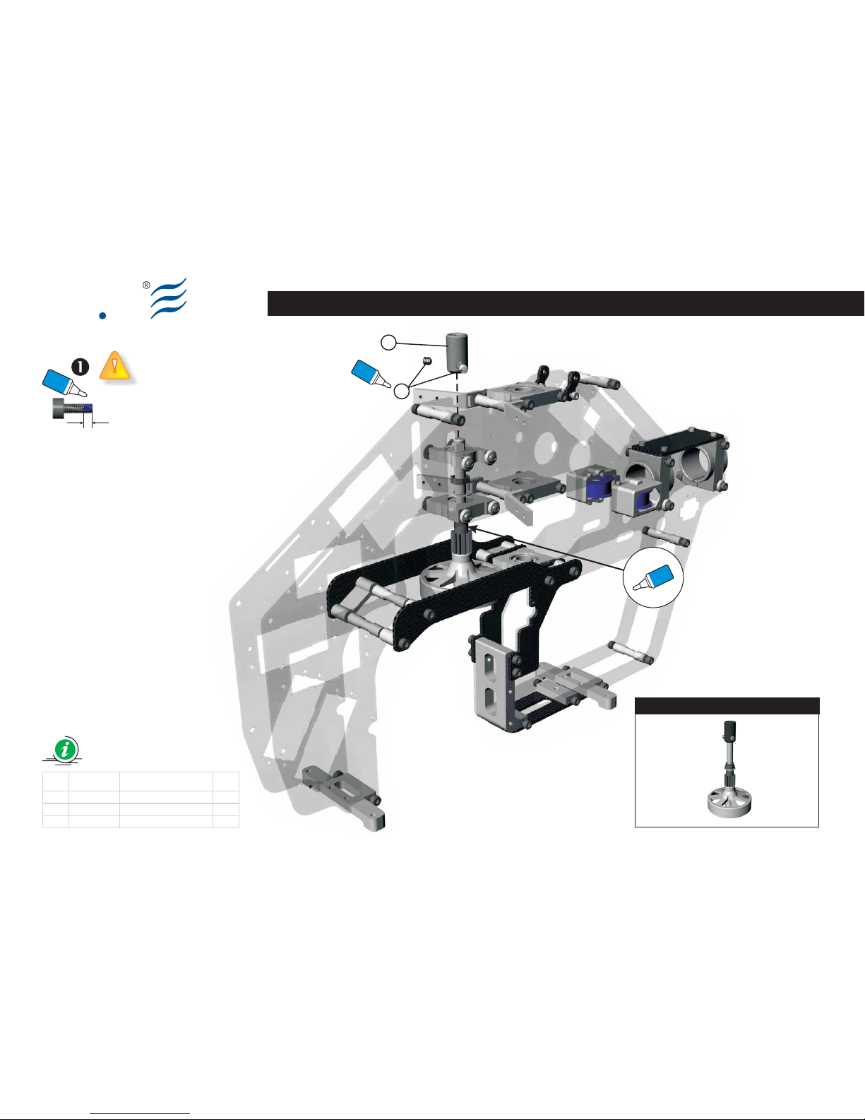
Clutch Bell Assy (Part 1.01)
BAG EQ3003
Glue width: approx. 1mm
Blue
Locktite
1
2
Item Code Description Q.ty
1 8100000A S tarter HEX Adapter 1
2 8204600A S et Sc rew M4x4 2
Vision 50 - Competition / Italy 13-05-2009
Preview
Blue
Locktite
Blue
Locktite
S005-3
Page 15

Ely
Q
S005-4 Vision 50 - Competition / Italy 13-05-2009
NOTES:
Page 16
Ely
Q
S006-1
Landing Skid Assy
BAG EQ3002
EN DE FRIT
(Bag EQ3002)
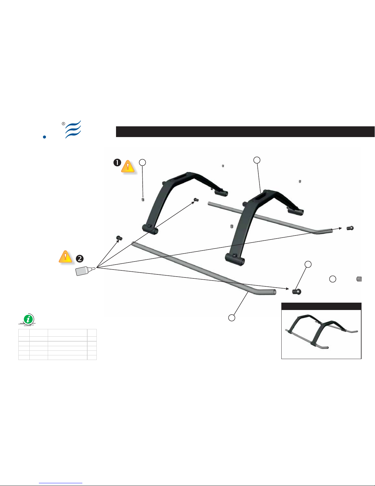
Landing Skid Assy
Insert the skid pipe (3) in the
corresponding holes of the Landing gear
strut (2).
Install the screws (4), according to the
drawing, but don't over tight them.
Use the Antenna tube (6) provided with
the EQ3021 helicopter package, unless
you are using a 2.4 GHz system.
Please keep the screws
perpendicular to the housing, and
make the first turns with caution, in
order to avoid breaking to the
corresponding housing.
Before installing the plastic End Caps
(1), please add a drop of thick CA glue
on the rim of the End Caps (1) and on the
inside edge of the Landing Pipes (2). Now
it is possible to fasten deeply the caps.
Tighten the fastening screws of the
skids with the pipes already
assembled
(Bag EQ3002)
Landing Skid Assy
Inserire i tubi (3) nei fori relativi dei
Landing gear strut (2).
Inserire e avvitare, senza fissare fino in
fondo, le viti (4) seguendo lo schema di
montaggio.
Il Tubo dell'antenna (6), qualora non si
utilizzasse un apparato TX-RX da 2,4Ghz,
deve essere montato secondo lo schema
e lo stesso è disponibile nella confezione
EQ3021.
Attenzione l’inserzione deve avvenire
cercando di mantenere la massima
perpendicolarità ed eseguendo i primi giri
con cautela al fine di evitare rotture alla
relativa sede.
Inserire per circa 1mm le coperture
in plastica (1) nei tubi (3) seguendo lo
schema di montaggio e assicurarsi che
rimanga sufficiente area prima della
battuta finale.
Versare una goccia di CA per parte
sull’area ancora scoperta della
copertura in plastica (1) e quindi inserire
fino in fondo nei rispettivi tubi (3).
Serrare le viti di fissaggio dei pattini
con i tubi, precedentemente
assemblati.
(Bag EQ3002)
Landing Skid Assy
Setzen Sie die Rohre (3) in den
entsprechenden Löchern der Landing
Gear Strut (2) ein.
Setzen Sie die Schrauben (4)ein und
schrauben Sie diese fest, ohne zu fest an
zuziehen. Folgen Sie dem Montagesche
ma.
Das Antennenrohr (6), muss montiert
werden, wenn kein Empfangssystem mit
2,4GHz benutzt wird. Es befindet sich in
der Verpackung EQ3021.
Achten Sie darauf, dass die
Schrauben (4) senkrecht eingesetzt
werden und dass die ersten Drehungen
vorsichtig ausgeführt werden, da ein
Überdrehen das Gewinde beschädigen
würde.
Setzen Sie die Kunststoffabdeckun
gen (1) ca. 1mm weit in die Rohre (3)
ein, indem Sie dem Montageschema
folgen und vergewissern Sie sich, dass
genug Platz vor dem Endanschlag bleibt.
Geben Sie nun einen Tropfen CASchnellkleber auf den Bereich, der noch
nicht mit der Kunststoffabdeckung
bedeckt ist (1) und drücken Sie diese
komplett in die Rohre (3) rein.
Fixieren Sie die Kufenrohre mit Hilfe
der Madenschrauben
(Bag EQ3002)
Landing Skid Assy
Introduire les tubes (3) dans les trous
relatifs des Landing gear strut (2).
Introduire et visser, sans fixer à fond, les
vis (4) en suivant le schéma de montage.
Le tube de l'Antenne (6), au cas où l'on
utilise un sytème à 2,4G, doit être monté,
il se trouve dans l'emballage EQ5021.
Attention l'insertion doit être
effectuée en cherchant à maintenir la
perpendicularité maximum et en
exécutant les premiers tours avec
précaution afin d'éviter des ruptures au
logement relatif.
Introduire environ 1mm des
couvertures en plastique (1) dans les
tubes (3) en suivant le schéma de
montage et vérifier qu'il reste un espace
suffisante avant la butée finale.
Verser une goutte de CA en partie sur la
zone encore découverte de la couver ture
en plastique (1) et ensuite l'introduire
dans les tubes (3).
Serrer les vis de fixation des patins
avec les tubes, précédemment
assemblés
Vision 50 - Competition / Italy 13-05-2009
Page 17
Ely
Q
Landing Skid Assy (Part 1.00)
4
3
2
1
S006-2
Cyano
acrylate
Item Code Description Q.ty
1 8003500A Sk id pipe end cap 4
2 8007800A Sk id Brac e 3D - V50 2
3 8103700A Landing gear s kid pipe 2
4 8204600A Set screw M4x 4 4
BAG EQ3002
Preview
Vision 50 - Competition / Italy 13-05-2009
Set Screw M4x4 (x4)
4
Page 18
Ely
Q
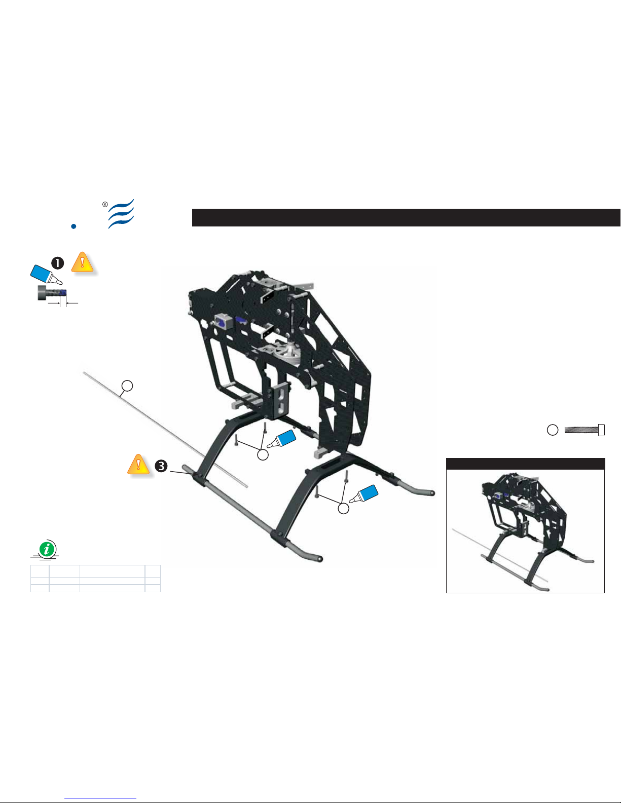
Landing Skid Assy (Part 1.01)
S006-3
BAG EQ3002
Vision 50 - Competition / Italy 13-05-2009
5
6
5
Preview
Item Code Description Q.ty
5 8203800A Sock et Sc rew M3x16 4
6 8006200A Antenna Tube 1
Glue width: approx. 1mm
Blue
Locktite
Blue
Locktite
Blue
Locktite
Socket screw M3x16 (x4)
5
Page 19
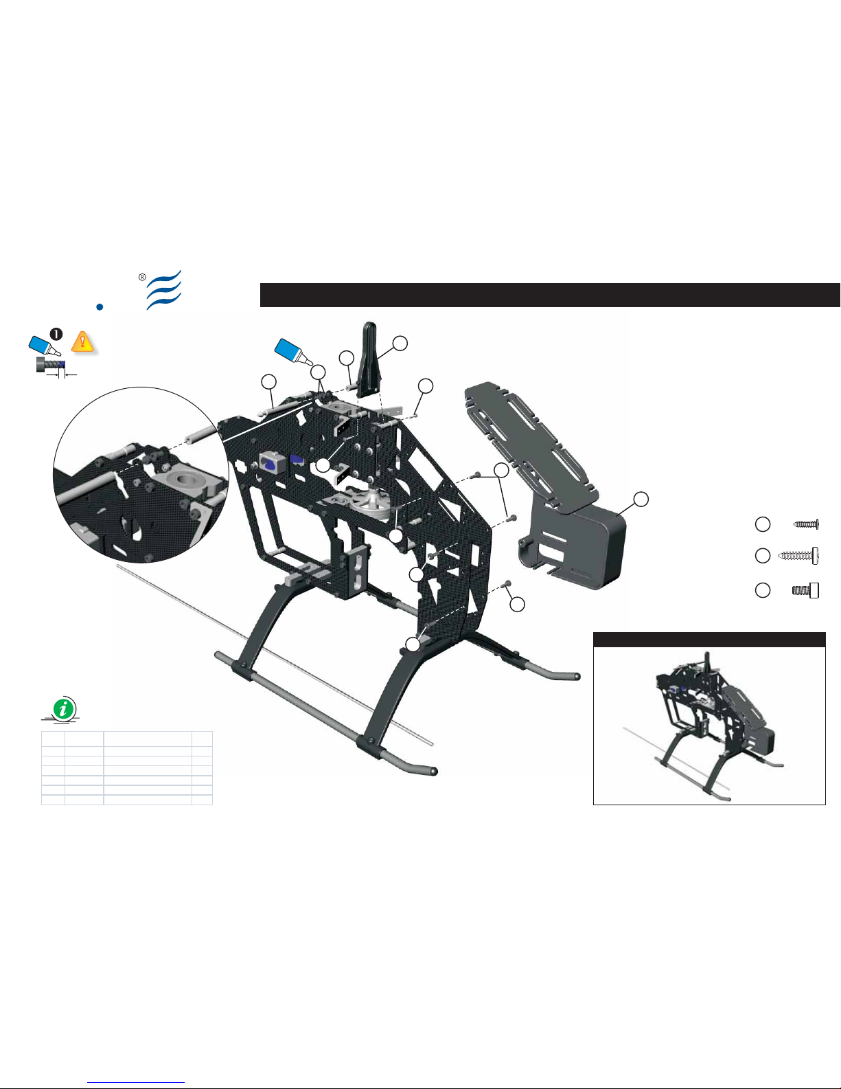
Main Frame Assembly (Part 2.00)
Ely
Q
BAG EQ3010
Glue width: approx. 1mm
Blue
Locktite
S004-4 Vision 50 - Competition / Italy 13-05-2009
Preview (V50 Competition)
3
4
4
2
5
6
6
6
6
6
1
1
Blue
Locktite
Socket screw M3x6 (x2)
Selftapping screw 3x12 (x6)
Selftapping screw 2x8 (x2)
3
6
4
Item Code Description Q.ty
1 8109200A Canopy M ounting (V50c ) 2
2 8010500A Ant irotati on (V50c) 1
3 8205200A Soc ket S crew M3x 6 2
4 8202500A Self Tapping Sc rew 2x8 2
5 8010100A Radio Tray (V50c ) 1
6 8200000A Self Tapping Sc rew 3x12 6
Page 20

Ely
Q
S008-1
EN DE FRIT
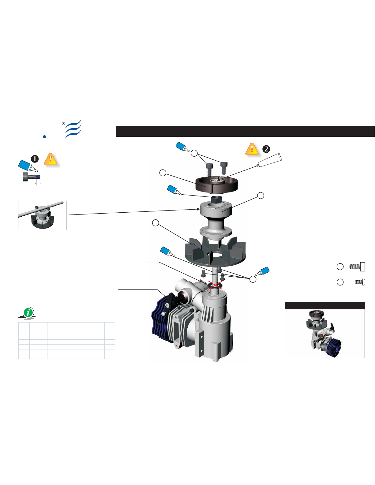
(Bag EQ3004)
Cooling Fan Assy
Make up the assy according to the
drawing.
First of all, secure the Fan (1) to the Hub
(3) using the Socket button head screws
(5). If the helicopter will be provided with
a “Governor” device, the Fan (1) is
already equipped with the corresponding
sensor housings (please see “Governor”
add-on – not included).
Un-mount the cover plate of the engine
crankcase and insert the corresponding
Crankshaft locking tool in order to fasten
the shaft (please see engine notes – not
included).
Add the sub-assembly to the engine
crankshaft. Then use the screws (4),
temporarily screw in the Hub (3), and
tighten the hub with an appropriate tool.
Remove the screws (4), fasten the prop
nut of the engine Crankshaft and mount
the Clutch (2) using the screws (4).
Remove the Crankshaft Clamp from the
engine, and then close the carter.
Each screw identified by the “Locktite”
symbol, must be impregnated with a
small drop of medium seal Locktite (blue)
along the entire length.
Add one-way bearing grease to the
corresponding Clutch (2). Repeat this
operation during the ordinary
maintenance of the helicopter.
(Bag EQ3004)
Cooling Fan Assy
Eseguire il montaggio seguendo lo schema.
Come prima operazione fissare la ventola
(1) all’HUB (3) utilizzando le viti (5). Qualora
si decidesse di utilizzare un dispositivo
”Governor” (regolatore di giri) la Ventola
(1) è già dotata delle opportune sedi per
l’accoglienza dei magneti (vedi istruzioni
allegate al “Governor” - non incluso).
Rimuovere il carter motore e inserire
l’apposito fermo (Crankshaft Clamp)
affinché l’albero motore non sia più libero
di ruotare (vedi istruzioni relative al motore
- non incluso).
Avvitare il gruppo all’albero motore
utilizzando le Viti (4) superiori,
provvisoriamente avvitate direttamente
sull’HUB (3) e fare leva, con un giravite
appositamente inserito (vedi fig.1),
assicurandone il giusto serraggio.
Rimuovere le viti (4), serrare
opportunamente il dado dell’albero
motore e montare il Clutch (2) fissandolo
con le viti (4). Rimuovere il fermo
(Crankshaft Clamp) di bloccaggio
dell’albero motore e richiudere il carter.
Ogni vite, identificata con il simbolo
“Locktite”, deve essere
preventivamente impregnata di Locktite a
tenuta media (blu).
Versare del grasso per cuscinetti
unidirezionali nel relativo Clutch (2).
Ripetere questa operazione durante la
periodica manutenzione dell’elicottero.
(Bag EQ3004)
Cooling Fan Assy
Führen Sie die Montage nach dem Schema aus.
Zuerst muss das Lüftungsrad (1) am HUB (3)
mit den Schrauben (5) fixiert werden. Für den
Fall, dasss Sie den Hubschrauber mit einem
Drehzahlregler (Governor) auszustatten
möchten, ist das Gebläse (1) bereits mit den
geeigneten Vertiefungen für die Sensoren (nicht
im Lieferumfang enthalten - beachten Sie ihre
beiliegende Anleitung des Drehzahlreglers)
ausgestattet.
Demontieren Sie den Boden des Motorgehäu
ses und setzen Sie die entsprechende Stift
schraube ein (Crankshaft Clamp), damit die
Welle blockiert wird (beachten Sie die Anleitung
des Motors – nicht im Lieferumfang).
Schrauben Sie die Gruppe an die Motorwelle an
und drehen Sie mit Hilfe der oberen Schrauben
(4), die provisorisch direkt auf dem HUB (3)
angeschraubt sind, mit einem Schraubendreher
(siehe Abb.1) die Baugruppe fest an. Entfernen
Sie die Schrauben (4), befestigen Sie die Schrau
benmutter (im Lieferumfang des Motor enthal
ten) auf die Motorwelle und montieren Sie die
Fliehkraft-Kupplung (Clutch (2)) mit den Schrau
ben (4). Entfernen Sie den Sicherungsstift (Cra
nkshaft Clamp) der Motorwelle und schließen
Sie das Gehäuse wieder.
Wo das Symbol “Locktite” angebracht ist,
muss jede Komponente mit Locktite mittel
fest (blau) gesichert werden.
Geben Sie Schmiermittel in den Freilauf der
Kupplung (Clutch (2)). Wiederholen Sie
diesen Vorgang während der regelmäßigen
Wartung des Hubschraubers.
(Bag EQ3004)
Cooling Fan Assy
Exécuter le montage en suivant le schéma.
Comme première opération fixer le
ventilateur (1) à l'HUB (3) au moyen des vis
(5). Au cas où l'on décide de doter
l'hélicoptère d'un dispositif ”Governor” le
ventilateur (1) est déjà doté des logements
opportuns pour accueillir des capteurs
(voir instructions aux gate au “Governor” non inclus).
Démonter le fond du carter moteur et
introduire le pivot spécialement prévu
(Crankshaft Clamp) afin que l'arbre se
bloque (voir instructions relatives au
moteur - non inclus).
Visser le groupe à l'arbre moteur et au
moyen des vis (4) supérieures,
provisoirement vissées directement sur
l'HUB (3), et un tournevis servant de levier,
en l'insérant entre celles-ci (voir fig.1),
jusqu'au serrage. Enlever les vis (4), fixer
solidement l'écrou de l'arbre moteur et
monter le Clutch (2) en le fixant avec les vis
(4). Enlever le pivot (Crankshaft Clamp) de
blocage de l'arbre moteur et refermer le
carter.
Chaque vis, où est reporté le symbole
“Locktite”, doit être au préalable
imprégnée de Locktite à tenue moyenne
(bleue).
Verser de la graisse pour roulements
unidirectionnels dans le Clutch (2)
relatif. Répéter cette opération pendant
l'entretien périodique de l'hélicoptère.
Cooling Fan Assy
BAG EQ3004
Vision 50 - Competition / Italy 13-05-2009
Page 21
Ely
Q
Cooling Fan Assy
Item Code Description Q.ty
1 8010000A F an V50c 1
2 8401000A Cl utch as sy 1
3 8100400B F an HUB 1
4 8202300A S ock et sc rew M4x8 2
5 8202400A S ock et butt on head sc rew M3x6 3
4
Blue
Locktite
3
2
1
5
Blue
Locktite
Blue
Locktite
Blue
Locktite
Grease
for one way bearing
Glue width: approx. 1mm
Blue
Locktite
S008-2
Engine not included
BAG EQ3004
Fig. 1
Non montare
Do not mount
Nicht montieren
Ne pas monter
Vision 50 - Competition / Italy 13-05-2009
Preview
Socket button head screw M3x6 (x3)
Socket Screw (x2) M4x8
5
4
Page 22
Ely
Q
S009-1
EN DE FRIT
(Bag EQ3004)
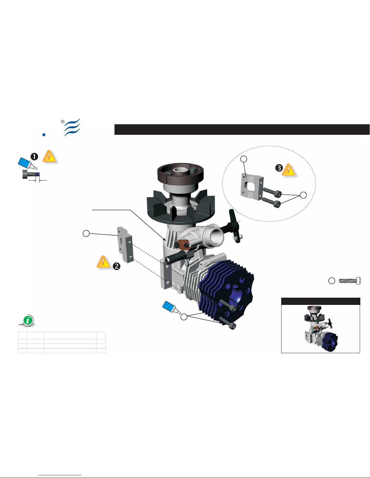
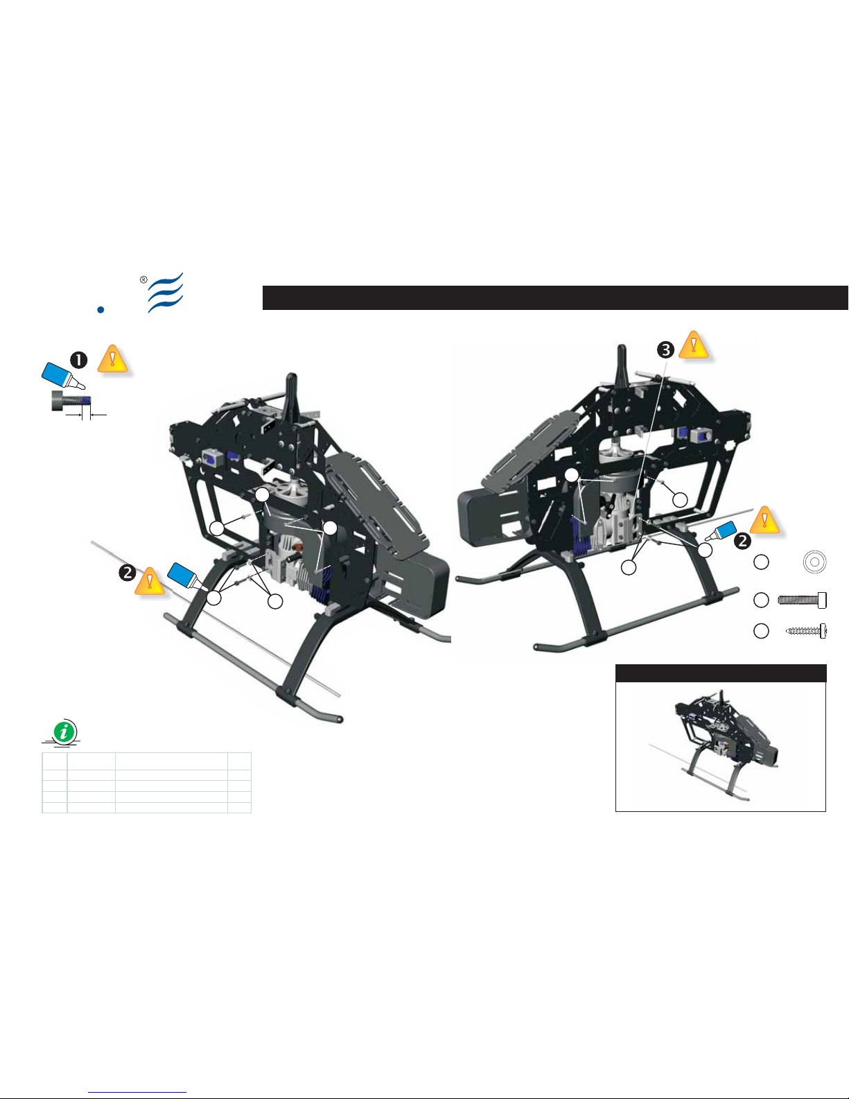
Engine Mount Assy
Make up the assy according to the
drawing.
Each screw identified by the “Locktite”
symbol, must be impregnated with a
small drop of medium seal locktite (blue)
along the entire length.
In this stage don't fix firmly the
screws because, once assembled the
helicopter, it is necessary to rotate the
engine starter shaft (using a starter) in
order to line up the structure.
Only after this operation, it is possible to
tighten the screws (2).
(Bag EQ3004)
Engine Mount Assy
Eseguire il montaggio seguendo lo
schema.
Ogni vite, identificata con il simbolo
“Locktite”, deve essere
preventivamente impregnata di Locktite
a tenuta media (blu).
In questa fase non serrare le Viti (2)
in quanto, una volta assemblato
l'elicottero, è necessario far girare a
vuoto, l'albero per l'avviamento del
motore, affinché si perfezioni
l'allineamento completo della meccanica.
Solo dopo questa operazione si potranno
serrare le Viti (2).
(Bag EQ3004)
Engine Mount Assy
Führen Sie die Montage nach dem
Schema aus.
Wo das Symbol “Locktite” angebracht ist,
muss jede Komponente mit Locktite
mittelfest (blau) gesichert werden
In dieser Phase nicht die Schrauben
(2) festziehen, weil es nach der
Montage des Hubschraubers notwendig
ist, das System über den Anlasser leer
laufen zu lassen.
Dies wird solange durchgeführt, bis
sich das System an die Struktur
angepasst hat. Erst nach diesem
Vorgang können die Schrauben
festgezogen werden (2).
(Bag EQ3004)
Engine Mount Assy
Exécuter le montage en suivant le
schéma.
Chaque vis, où est reporté le symbole
“Locktite”, doit être au préalable
imprégnée de Locktite à tenue moyenne
(bleue).
Dans cette phase ne pas serrer les
vis (2) car, une fois monté
l'hélicoptère, il est nécessaire de faire
tourner le système à vide, au moyen de la
visseuse.
Ceci afin que celui-ci s'aligne avec la
structure. Seulement après cette
opération les vis (2) pourront être
serrées.
BAG EQ3004
Engine Mount Assy
Vision 50 - Competition / Italy 13-05-2009
Page 23
Ely
Q
Engine Mount Assy
1
1
2
S009-2
Blue
Locktite
Glue width: approx. 1mm
Blue
Locktite
Engine not included
Item Code Description Q.ty
1 8108500A Motor Mount Side (V50c ) 2
2 8200900A Sock et s crew M3x14 4
BAG EQ3004
Preview
Vision 50 - Competition / Italy 13-05-2009
2
Socket screw M3x14 (x8)
2
Page 24
Ely
Q
Glue width: approx. 1mm
Blue
Locktite
BAG EQ3004-10
S009-3
Item Code Description Q.ty
1 8203700A Sel f Tapping Screw 2.5x 12 6
2 8200900A Soc ket Screw M3x14 4
3 8201200A Flat Was her d3, D8, W 1.5 4
4 8010200B Engi ne Fan Conveyor 1
Preview
Vision 50 - Competition / Italy 13-05-2009
Socket screw M3x14 (x4)
Self Tapping screw M2.5x12 (x6)
Washer d3,D8,W1.5 (x4)
3
2
1
3
2
2
3
1
1
4
1
1
Blue
Locktite
Blue
Locktite
Main Frame Assembly (Part 2.01)
Page 25
S009-4 Vision 50 - Competition / Italy 13-05-2009
Ely
Q
BAG EQ3004-10
Main Frame Assembly (Part 2.02)
Page 26

Ely
Q
S010-1
EN DE FRIT
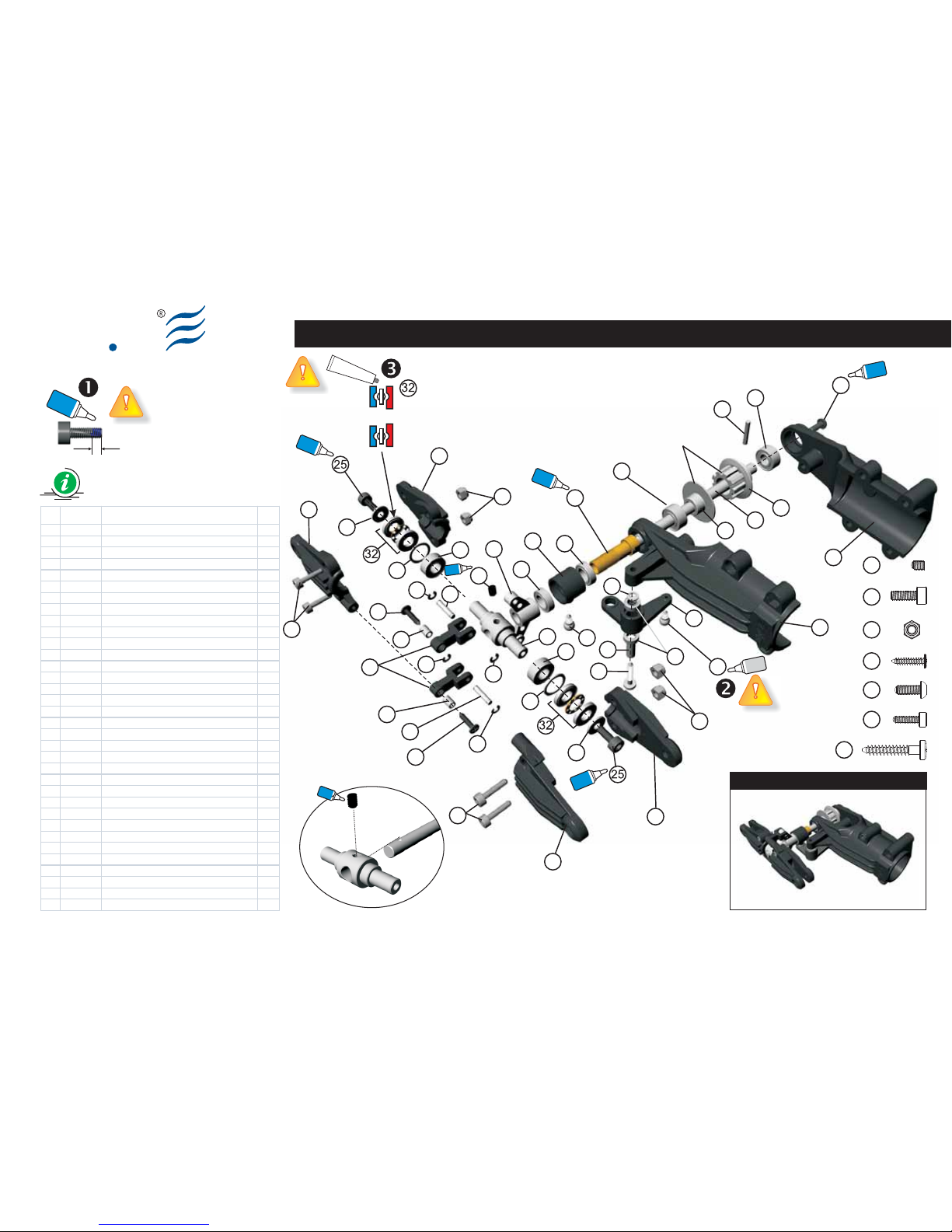
(Bag EQ3005)
Tail Unit Assy
Make up the assy according to the
drawing.
Please take care of the PIN (13) and
screw (34) subassemblies. These
components must be tighten firmly and
the screw must be impregnated with a
small drop of medium seal locktite (blue).
The Self Tapping screws (20) and (24)
must not be over tighten, because they
must ensure a good seal without over
fastening.
Each screw identified by the “Locktite”
symbol, must be impregnated with a
small drop of medium seal Locktite (blue).
Add a tiny drop of thick CA on the Ball
Type A (14), which are to be ensured
respectively to the Tail pitch control lever
(3) and to the Tail rotor control slider ring
(10).
Insert bearing grease over the
Thrust Bearing (32). This bearing
has two external surfaces and a cage
containing little steel balls. This cage has
edges that have to be inserted towards
the surface of the bearing with the wider
diameter.
(Bag EQ3005)
Tail Unit Assy
Eseguire il montaggio seguendo lo schema.
Le parti che richiedono attenzione sono il
PIN (13) e la vite (34). Questi componenti
devono essere serrati molto bene e la vite
deve essere impregnata di Locktite media
(blu).
Le viti autofilettanti (20) e (24) non devono
essere serrate in maniera eccessiva. Le
stesse devono assicurare una buona
tenuta ma senza eccedere nel serraggio.
Ogni vite, dove è riportato il simbolo
“Locktite”, deve essere
preventivamente impregnata di Locktite a
tenuta media (blu).
Versare una goccia di collante rapido
CA sulle Ball Type A (14) da fissare
rispettivamente al Tail pitch control lever
(3) ed al Tail rotor control slider ring (10)
Lubrificate il Thrust Bearing (32) con
del grasso per cuscinetti.
Questo reggispinta si compone di tre
parti: la gabbia che ospita le sfere deve
essere compresa tra le altre due parti
aventi superficie concava. La parte della
gabbia che presenta il bordo dovrà essere
rivolta verso la superficie del cuscinetto
con il diametro interno più largo.
(Bag EQ3005)
Tail Unit Assy
Führen Sie die Montage nach dem Schema
aus.
Die Teile, die mit großer Sorgfalt montiert
werden müssen, sind PIN (13) und die
Schrauben (34).
Diese Komponenten müssen sehr gut
angezogen werden und die Schrauben
müssen mit Locktite mittelfest (blau)
gesichert werden.
Die selbstschneidenden Schrauben (20
und 24) müssen einen guten Halt
garantieren, ohne diese zu überdrehen.
Wo das Symbol “Locktite” angebracht
ist, muss jede Komponente mit Locktite
mittelfest (blau) gesichert werden.
Geben Sie einen Tropfen CA-
Schnellkleber auf die Ball Type A (14),
die an den Tail Pitch Control Lever (3) und
Tail Rotor Control Slider Ring (10) befestigt
werden.
Geben Sie Schmieröl auf die Lager für
Thrust Bearing (32).
Dieses Lager hat zwei Außenflächen
und ein Gehäuse, wo die Stahlkügelchen
eingesetzt sind. Dieses Gehäuse hat
Kanten, die in Richtung der Oberfläche des
Lagers mit dem breiteren Durchmesser
eingesetzt werden müssen.
(Bag EQ3005)
Tail Unit Assy
Exécuter le montage en suivant le
schéma.
Les parties qui requièrent plus d'attention
sont le PIN (13) et la vis (34). Ces
composants doivent être très bien serrés
et la vis doit être imprégnée de Locktite à
tenue moyenne (bleue).
Les vis auto-taraudeuses (20) et (24) ne
doivent être excessivement serrées.
Celles-ci doivent assurer une bonne tenue
mais sans excéder dans le serrage.
Chaque vis, où est reporté le symbole
“Locktite”, doit être au préalable
imprégnée de Locktite à tenue moyenne
(bleue).
Verser une goutte de colle rapide CA
sur les Ball Type à (14) qui sont
respectivement fixées au Tail pitch control
lever (3) et au Tail rotor control slider ring
(10).
Insérez de la graisse pour
roulements sur le Thrust Bearing
(32).
Ce coussinet présente deux surfaces
externes et une cage où sont insérées les
billes en acier. Cette cage de tenue
présente des bords; les bords devront
être insérés vers la surface du coussinet
avec le diamètre plus large.
Tail Unit Assy
BAG EQ3005
Vision 50 - Competition / Italy 13-05-2009
Page 27
Glue width: approx. 1mm
Blue
Locktite
31
30
33
33
30
29
29
28
28
28
28
27
27
26
26
24
24
23
23
21
22
22
20
34
19
18
17
16
15
15
16
14
14
13
12
11
10
9
8
7
6
5
5
4
4
3
2
1
Tail Unit Assy
Ely
Q
Blue
Locktite
Blue
Locktite
Blue
Locktite
Blue
Locktite
Blue
Locktite
Cyano
acrylate
Preview
Bag EQ3005
Large Internal Diameter
always go toward the
tail Rotor HUB
Small Internal Diameter
always go toward the Blade
Grease
Vision 50 - Competition / Italy 27-07-2009
Socket screw M2.5x8 (x4)
29
Socket B.H. screw M3x8 (x1)
34
25
Lock Nut M2.5 (x4)
30
Self Tapping Screw 3x18 (x1)
20
Set Screw M3x4 (x1)
34
Self Tapping Screw 2x10 (x2)
24
S010-2
Blue
Locktite
Socket screw M3x8 (x2)
Item Code Description Q.ty
1 8107400B Tail P ulley Flange (Met al) 1
2 8107500B 8107500B+ 8107900B Tail Pul ley (M etal) 1
3 8001200B Tail pi tc h control lever 1
4 8001300B Tail hous ing (L) 2
5 8001400B Tail hous ing (R) 2
6 8001600A Tail uni t hous ing (R) 1
7 8001700A Tail uni t hous ing (L) 1
8 8107300A Tail P itc h Control Fork (Metal ) 1
9 8001900A Tail pi tc h control link 2
10 8002000A Tail rotor c ontrol s lider ri ng 1
11 8100900C Tail rot or hub SUS 1
12 8101300A Tail rotor s haft 1
13 8101500A Pin 2x 12 1
14 8101600A Self Tapping Bal l ty pe A 2
15 8101700A Pin 2x 10 2
16 8101800A Collar d2, D3, W4.3 2
17 8101900A Collar d3, D4, W10 1
18 8102000A Tail pitc h slider bushi ng 1
19 8201300A Flat was her d3, D5, W 0.5 1
20 8200100A Self tappi ng sc rew 3x18 1
21 8200200A Set s crew M3x4 1
22 8600400A Bearing d5, D11, W5 2
23 8600500A Bearing d5, D10, W4 2
24 8200300A Self tappi ng sc rew 2x10 2
25 8201800A Sock et Sc rew M3x8 2
26 8204800A Flat was her d7.5, D10, W0. 5 2
27 8600600A Bearing d6, D10, W3 2
28 8200600A E-ring 4
29 8204700A Sock et sc rew M2.5x 8 4
30 8200800A Lock nut M2.5 4
31 8601100A Bearing d4, D7, W2. 5 2
32 8601800A Thrust Beari ng d5, D10, W 4 2
33 8205600A Washer d3, D8, W0. 75 2
34 8201900A Sock et But tom Head Sc rew M3x8 1
Check page S025 for your release
Check page S025
for your release
Page 28

Ely
Q
S011-1
EN DE FRIT
(Bag EQ3006)
Tail Support Rod Assy
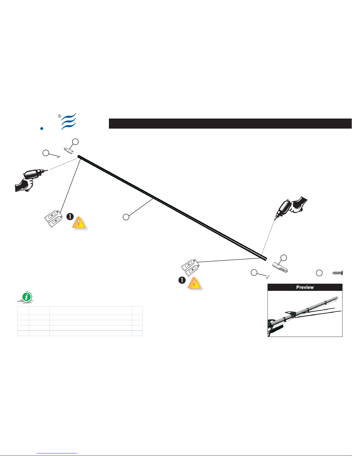
Make up the assy according to the
drawing.
The Self Tapping screws (3) must not be
over tighten, because they must ensure a
good seal without over fastening.
(Bag EQ3006)
Tail Support Rod Assy
Eseguire il montaggio seguendo lo
schema.
Le viti autofilettanti (3) non devono
essere serrate in maniera eccessiva. Le
stesse devono assicurare una buona
tenuta ma senza eccedere nel serraggio.
Incollare con
epossidica (30min.)
(Bag EQ3006)
Tail Support Rod Assy
Führen Sie die Montage nach dem
Schema aus.
Die selbstschneidenden Schrauben (3)
müssen einen guten Halt garantieren,
ohne diese zu überdrehen.
(Bag EQ3006)
Tail Support Rod Assy
Exécuter le montage en suivant le
schéma.
Les vis auto-taraudeuses (3) ne doivent
être excessivement serrées. Celles-ci
doivent assurer une bonne tenue mais
sans excéder dans le serrage.
Tail Support Rod Assy
BAG EQ3006
Vision 50 - Competition / Italy 13-05-2009
Page 29
2
Item Code Description Q.ty
1 8106600A Tail S upport Rod End (Metal) 4
2 8008100A Carbon Fiber Tail Support Rod d4,D6,W490 2
3 8202500A Self tapping screw 2x8 4
Tail Support Rod Assy
Ely
Q
S011-2
1
1
3
3
BAG EQ3006
Vision 50 - Competition / Italy 13-05-2009
Epoxy
Epoxy
Ø 1.5mm
Ø 1.5mm
Selftapping screw 2x8 (x4)
3
Page 30

Ely
Q
S012-1
EN DE FRIT
(Bag EQ3007 - EQ3021)
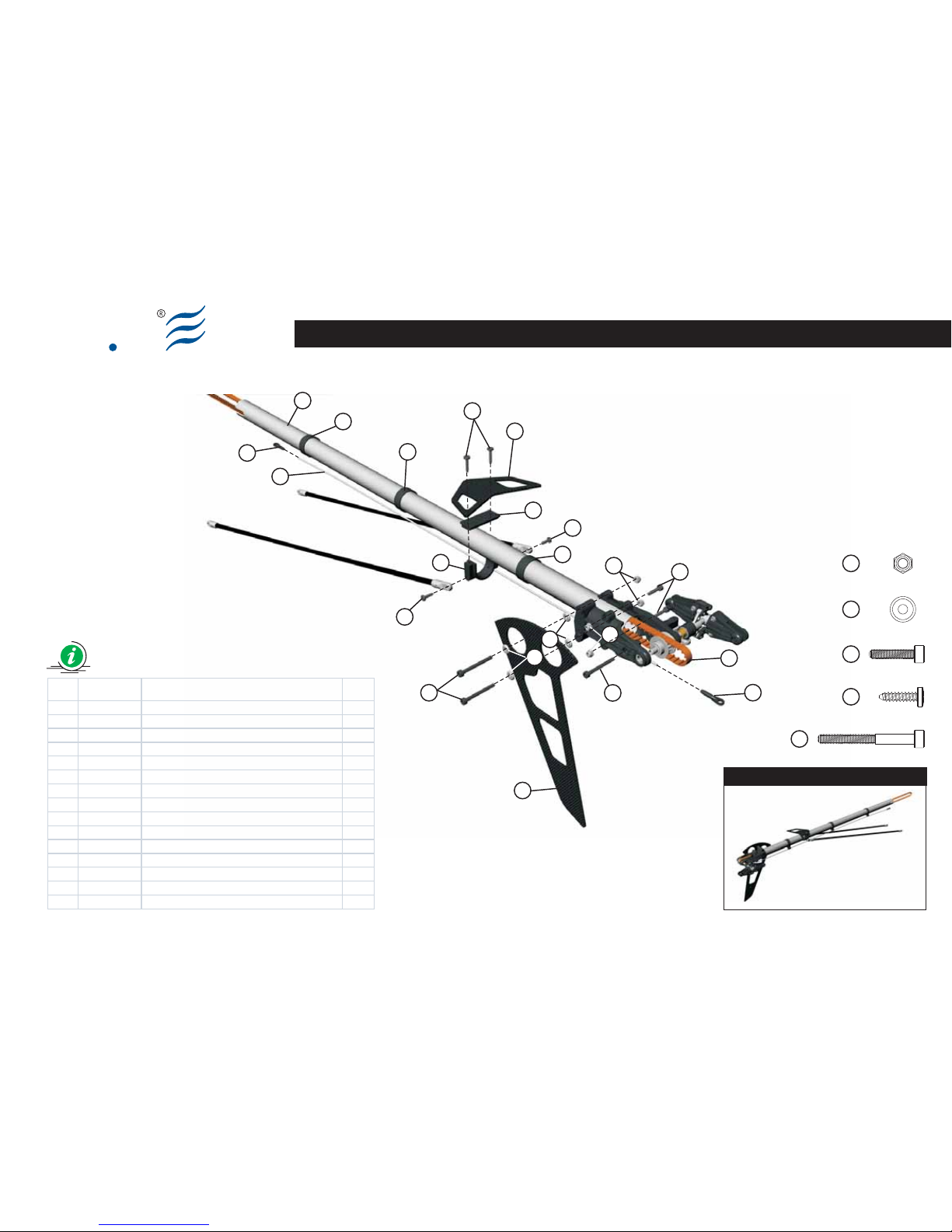
Tail Assy
Make up the assy according to the
drawing.
Be sure that the Tail Drive Belt (7) is
added inside the tail boom (8) without
rotating.
In the subsequent assemblies, the belt
should be rotated of 90 degrees so that
the tail blades revolve clockwise.
We suggest to envelope the end of the
Tail Drive Belt (7) using adhesive tape to
make easy the insertion. The tape will be
removed once mounted the Tail Drive
Belt (7) into the autorotation pulley.
(Bag EQ3007 - EQ3021)
Tail Assy
Eseguire il montaggio seguendo lo
schema.
Assicurasi che la cinghia (7) venga
inserita senza effettuare rotazioni
all’interno del tubo di coda (8).
Successivamente si dovrà effettuare una
rotazione della stessa di 90 gradi
affinché le pale di coda ruotino in senso
antiorario
Per agevolare l’inserimento della cinghia
(7) nel tubo di coda (8) si suggerisce di
avvolgerne con del nastro adesivo
l’estremità.
Il nastro verrà rimosso in fase di
montaggio della stessa sulla ruota di
trasmissione.
(Bag EQ3007 - EQ3021)
Tail Assy
Führen Sie die Montage nach dem
Schema aus.
Vergewissern Sie sich, dass der Riemen
(7) ohne Drehungen im Heckrohr (8)
montiert wird. Bei der späteren
Heckrohrmontage muss eine 90°
Drehung durchgeführt werden, sodass
sich der Heckrotor gegen den
Uhrzeigersinn dreht.
Um das Einsetzen des Riemens (7) in das
Heckrohr (8) zu erleichtern, wird
empfohlen, um das Ende des Riemens (7)
ein Klebeband zu wickeln. Das Klebeband
wird bei der Montagephase des
Heckriemens auf dem Antriebsrad
entfernt.
(Bag EQ3007 - EQ3021)
Tail Assy
Exécuter le montage en suivant le
schéma.
Vérifier que la courroie (7) soit insérée
sans effectuer de rotations à l'intérieur
du tube de queue (8). dans les montages
successifs on devra effectuer une
rotation de celle-ci de 90 degrés afin que
les pales de queue tournent dans le sens
contraire à celui des aiguilles d'une
montre.
Pour faciliter l'insertion de la courroie (7)
dans le tube de queue (8) on conseille
d'enrubanner l'extrémité de la courroie
(7). Le ruban sera enlevé en phase de
montage de la courroie sur la roue de
transmission.
Tail Assy
BAG EQ3007-22
Vision 50 - Competition / Italy 13-05-2009
Page 31
10
12
12
14
11
10
10
9
8
7
6
6
5
4
3
2
1
1
1
Tail Assy
Ely
Q
Preview
Vision 50 - Competition / Italy 13-05-2009S012-2
11
13
13
Lock Nut M3 (x4)
11
14
Socket screw M3x14 (x2)
13
Washer d3,D8,W1.5 (x4)
10
Selftapping screw 3x12 (x4)
12
Socket screw M3x30 (x3)
Item Code Description Q.ty
1 8000800A Tail c ontrol guide 3
2 8002200A Horizontal fin clam p lower 1
3 8002300A Horizontal fin clam p upper 1
4 8002500A Horizontal Stabilizer CF 1
5 8002600A V ertic al Stabilizer CF 1
6 8002700A B all link A 2
7 8006000A 686XL Tail Drive Belt 1
8 8009200A Tail B oom V50 with Logo (Carbon Fiber) 1
9 8105900A S US Rear Servo ROD 620mm (L-V2) 1
10 8200000A Self tapping sc rew 3x12 4
11 8200400A Lock nut M3 4
12 8201700A Socket screw M3x30 3
13 8201200A Flat Was her d3,D8,W 1.5 4
14 8200900A Socket screw M3x14 2
BAG EQ3007-21
Page 32

Ely
Q
S013-1
EN DE FRIT
(Bag EQ3008)
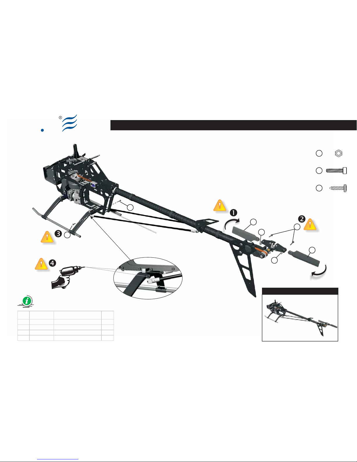
Main Frame Assembly (Part 01.2)
Make up the assy according to the
drawing.
Be sure that the Tail Rotor Blades (1)
are insert according to the picture,
and that the entering edge is added
making an anti-clockwise rotation (please
look at the rotation arrow).
The screws (2) must not be over
tighten, because the Tail Rotor Blades
(1) must have a proper degree of
freedom, moving without interferences.
The blades will completely stretch once
started the rotation.
The self tapping screws (4) must not
be over tighten, because they must
ensure a good seal without over
fastening.
(Bag EQ3008)
Main Frame Assembly (Part 01.2)
Eseguire il montaggio seguendo lo
schema.
Assicurarsi che i palini di coda (1)
siano inseriti secondo lo schema di
montaggio e che ambedue i bordi di
entrata degli stessi siano orientati in
modo da seguire una rotazione antioraria
(vedi freccia di rotazione)
Le viti (2) non devono essere serrate.
I palini di coda (1) devono essere liberi
di muoversi senza particolare resistenza:
si distenderanno completamente appena
inizierà la fase di rotazione.
Le viti autofilettanti (4) non devono
essere serrate in maniera
eccessiva.
Le stesse devono assicurare una buona
tenuta ma senza eccedere nel serraggio.
Eseguire un foro, su entrambi i lati,
nella posizione evidenziata in figura,
usando una punta da 2mm di diametro.
(Bag EQ3008)
Main Frame Assembly (Part 01.2)
Führen Sie die Montage nach dem
Schema aus.
Vergewissern Sie sich, dass die
Heckrotorblätter (1) nach dem
Montageschema montiert werden und
dass die Heckrotorblätter mit der
Vorderkante gegen den Uhrzeigersinn
eingesetzt werden (siehe Rotationspfeil).
Die Schrauben (2) dürfen nicht fest
angezogen werden.
Die Heckrotorblätter (1) müssen sich frei
ohne großen Krafteinwand bewegen
können. Sie werden sich komplett
ausdehnen, sobald der Heckrotor in
Drehung versetzt wird.
Die selbstschneidenden Schrauben
(4) müssen einen guten Halt
garantieren, ohne diese zu
überdrehen.
(Bag EQ3008)
Main Frame Assembly (Part 01.2)
Exécuter le montage en suivant le
schéma.
Vérifier que les pales de queue (1)
soient insérées selon le schéma de
montage et que le bord d'entrée de ce
dernier soit inséré en suivant une
rotation dans le sens contraire à celui
des aiguilles d'une montre (voir flèche de
rotation)
Les vis (2) non doivent être serrées.
Les pales de queue (1) doivent être
libres de se déplacer sans grandes
interférences; elles se détendront
complètement une fois mises en rotation.
Les vis auto-taraudeuses (4) ne
doivent pas être excessivement
serrées.
Celles-ci doivent assurer une bonne tenue
mais sans excéder dans le serrage.
Main Frame Assembly (Part 3.00)
BAG EQ3008
Vision 50 - Competition / Italy 13-05-2009
Page 33
4
4
3
3
2
1
1
Preview
Ely
Q
S013-2
Main Frame Assembly (Part 3.00)
Ø 2mm
Lock Nut M3 (x2)
Socket screw M3x14 (x2)
Selftapping screw 3x12 (x2)
Item Code Description Q.ty
1 8005100A Tail Rotor Blade 2
2 8200900A Soc ket screw M3x14 2
3 8200400A Lock nut M3 2
4 8200000A Self tapping sc rew 3x12 2
BAG EQ3008
Vision 50 - Competition / Italy 13-05-2009
3
2
4
Page 34

Ely
Q
S014-1
EN DE FRIT
(Bag EQ3011)
Main Drive Gear Assembly
Make up the assy according to the
drawing.
The One Way Auto-rotation Assy comes
assembled from the factory. However, we
suggest making a quality check.
Each screw identified by the “Locktite”
symbol, must be impregnated with a
small drop of medium seal Locktite (blue).
Add one-way bearing grease (please
see the One Way Auto-Rotation Assy
subassembly) during the ordinary
maintenance of the helicopter.
(Bag EQ3011)
Main Drive Gear Assembly
Eseguire il montaggio seguendo lo
schema.
Il gruppo One Way Auto-rotation Assy
viene fornito già assemblato. Verificare
comunque la qualità dell’assieme.
Ogni vite, dove è riportato il simbolo
“Locktite”, deve essere
preventivamente impregnata di Locktite
a tenuta media (blu).
Inserire del grasso per cuscinetti
unidirezionali (vedi schema del gruppo
One Way Auto-Rotation Assy) durante le
manutenzioni periodiche.
(Bag EQ3011)
Main Drive Gear Assembly
Führen Sie die Montage nach dem
Schema aus.
Die Gruppe One Way Auto-Rotation Assy
wird bereits fertig montiert geliefert.
Kontrollieren Sie die Baugruppe trotzdem
auf die richtige Montage.
Wo das Symbol “Locktite“ angebracht
ist, muss jede Schraube vorsorglich
mit Locktite mittelfest gesichert (blau)
werden.
Geben Sie Schmieröl in den Freilauf
(siehe Schema der Gruppe One Way
Auto-Rotation Assy)Auch während der
regelmäßigen Wartung.
(Bag EQ3011)
Main Drive Gear Assembly
Exécuter le montage en suivant le
schéma.
Le groupe One Way Auto-rotation Assy
est fourni déjà assemblé. Vérifier
toutefois la qualité de l'ensemble.
Chaque vis, où est reporté le symbole
“Locktite”, doit être au préalable
imprégnée de Locktite à tenue moyenne
(bleue).
Introduire de la graisse pour
roulements unidirectionnels (voir
schéma du groupe One Way Auto-
Rotation Assy) pendant les entretiens
périodiques.
Main Drive Gear Assembly
BAG EQ3011
Vision 50 - Competition / Italy 13-05-2009
Page 35

6
8
7
Preview
Vision 50 - Competition / Italy 13-05-2009
Ely
Q
Main Drive Gear Assembly
Item Code Description Q.ty
1 8109900A O ne Way Housing with Logo (V50c) 1
2 8110000A O ne Way Shaft (V50c ) 1
3 8600700A O ne way bearing d14, D20, W16 1
4 8110100A O neWay Shaft Collar (V50c ) 1
5 8602300A B earing d15, D21, W4 2
6 8201800A S ock et Sc rew M3x8 4
7 8003900A A utorotat ion Pull ey 1
8 8004900B 96T Main Gear 1
4
5
5
1
2
3
One Way Auto
Rotation Assy
Blue
Locktite
Grease
for one way bearing
6
Socket screw M3x8 (x4)
Glue width: approx. 1mm
Blue
Locktite
S014-2
BAG EQ3011
Page 36

Ely
Q
S015-1
EN DE FRIT
(Bag EQ3012)
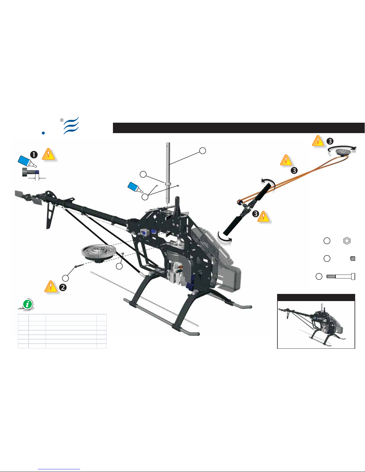
Main Frame Assy (Part 02.1)
Make up the assy according to the
drawing.
Add first the Main Drive Gear Assy
(previously assembled) and line up the
corresponding holes with main shaft
bearing holes.
Add the main shaft (1) and tighten the
socket screw (4) and the lock nut (5).
Insert the Collar (2) and tighten the
screws (3) keeping in traction the main
shaft (1).
Each screw identified by the “Locktite”
symbol, must be impregnated with a
small drop of medium seal Locktite (blue).
Don't over tighten the lock nut (5) and
the socket screw (4). An excessive
pressure could damage the tail
transmission gear.
Please control the Tail Belt rotation
direction: the clockwise direction of
the main rotor must be transmitted and
converted in anti-clockwise rotation of
the Tail Rotor Blade.
(Bag EQ3012)
Main Frame Assy (Part 02.1)
Eseguire il montaggio seguendo lo
schema.
Inserire prima il gruppo Main Drive Gear
Assy precedentemente assemblato e
allineare il foro di quest’ultimo con i fori
dei cuscinetti dell’albero principale. .
Inserire l'Albero Principale (1) e fissare il
Dado (5) con la Vite (4).
Inserire il collare (2) e tenendo sollevato
l’albero principale (1) serrare le viti (3).
Ogni vite, identificata con il simbolo
“Locktite”, deve essere
preventivamente impregnata di Locktite
a tenuta media (blu).
Non serrare eccessivamente la vite
(4) e il dado (5); l’eccessiva pressione
potrebbe incrinare la corona della
trasmissione di coda.
Verificare il senso di rotazione della
Tail Belt Driver (cinghia di coda) in
modo che il movimento in senso orario
del rotore principale venga trasmesso e
convertito in rotazione antioraria dei Tail
Rotor Blades.
(Bag EQ3012)
Main Frame Assy (Part 02.1)
Führen Sie die Montage nach dem
Schema aus.
Setzen Sie die Gruppe Main Drive Gear
Assy ein, die zuvor montiert wurde.
Passen Sie die Bohrung der
Hauptrotorwelle (1) mit dem des Main
Drive Gear Assy (2) an. Setzen Sie die
Hauptrotorwelle ein (1) und fixieren Sie
die Schraubenmutter (5) und die
Schraube (4).
Den Sicherungsring (2) auf die
Hauptrotorwelle (2) aufsetzen und mit
den Madenschrauben (3)
, beim
hochhalten der Baugruppe an der
Hauptrotorwelle, fixieren.
Jede Schraube, an der das Symbol
“Locktite” angebracht ist, muss mit
Locktite mittelfest (blau) gesichert
werden.
Ziehen Sie die Schraube (4) und die
Schraubenmutter (5) nicht zu fest an;
zu starker Druck könnte den Kranz des
Heckantriebs beschädigen.
Kontrollieren Sie die Drehrichtung der
Tail Belt Driver, damit die Drehung im
Uhrzeigersinn des Hauptrotors übertragen
wird und in die Drehung gegen den
Uhrzeigersinn der Heckrotorblätter
umgelenkt wird.
(Bag EQ3012)
Main Frame Assy (Part 02.1)
Exécuter le montage en suivant le
schéma.
Introduire en premier le groupe Main
Drive Gear Assy précédemment
assemblé et aligner le trou de ce dernier
avec les trous des roulements de l'arbre
principal.
Introduire l'arbre principal (1) et fixer
l'écrou (5) et la vis (4).
Introduire le collier (2) et maintenant en
traction l'arbre principal (1) serrer les vis
(3).
Chaque vis, où est reporté le symbole
“Locktite”, doit être au préalable
imprégnée de Locktite à tenue moyenne
(bleu).
Ne pas serrer excessivement la vis
(4) et l'écrou (5); l'excessive pression
pourrait endommager la couronne de la
transmission de queue.
Vérifier le sens de rotation de la TaLe
Belt Driver de façon à ce que la
rotation dans le sens des aiguilles d'une
montre du rotor principal soit transmise
et convertie en rotation dans le sens
contraire des aiguilles d'une montre des
Tail Rotor Blade.
Main Frame Assy (Part 3.01)
BAG EQ3012
Vision 50 - Competition / Italy 13-05-2009
Page 37
Main Frame Assy (Part 3.01)
Ely
Q
Preview
4
3
2
5
1
Item Code Description Q.ty
1 8109800A M ain Shaft (V 50c) 1
2 8100800A M ain Shaft Coll ar 1
3 8204600A S et screw M4x4 2
4 8203400A S ock et Sc rew M3x20 (13+7) 1
5 8200400A Loc k Nut M3 1
Glue width: approx. 1mm
Blue
Locktite
S015-2
Lock Nut M3 (x1)
5
Set Screw M4x4 (x2)
3
Socket Screw M3x20 (13+7) (x1)
4
BAG EQ3012
Vision 50 - Competition / Italy 13-05-2009
Blue
Locktite
Page 38

Ely
Q
S016-1
EN DE FRIT
(Bag EQ3013)
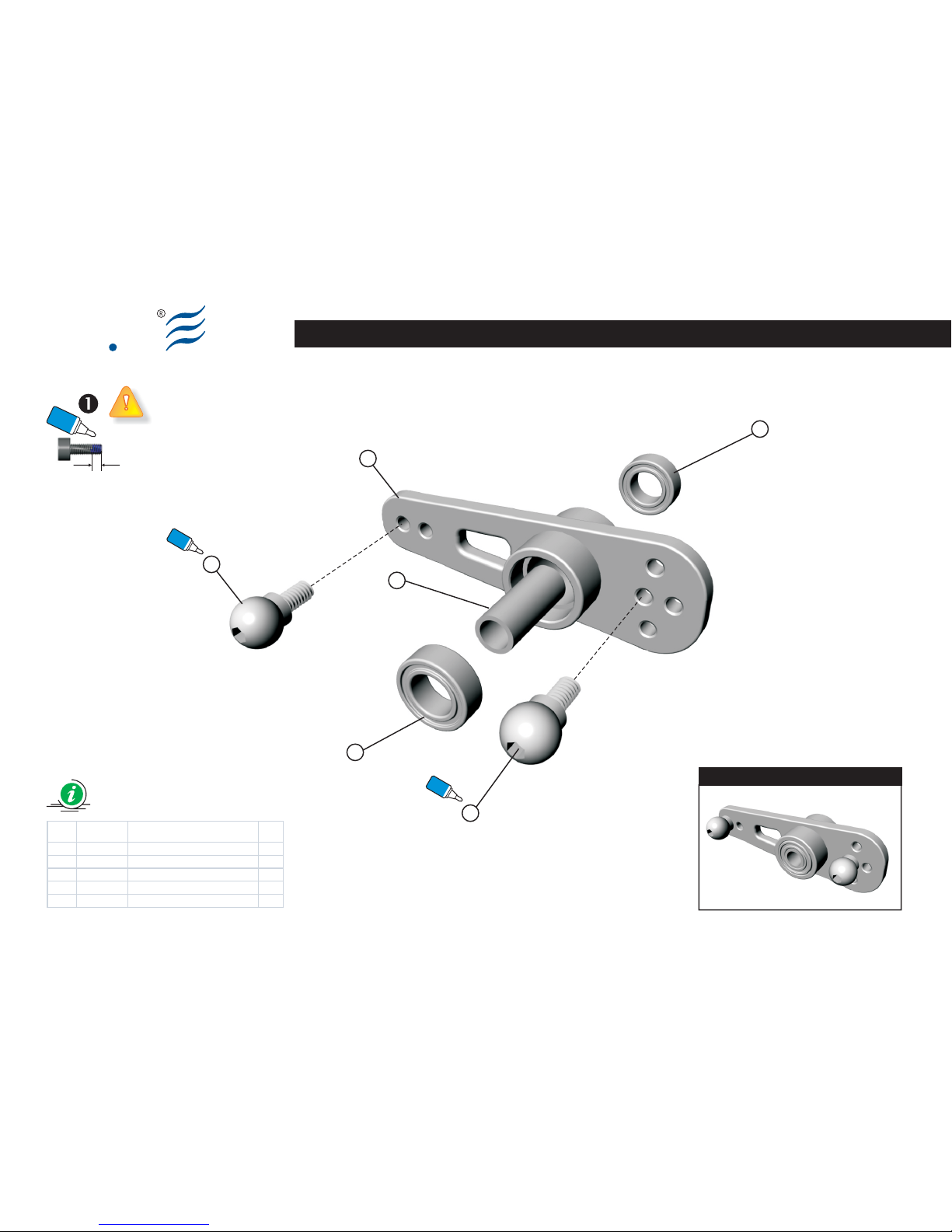
Mixing Lever Assy
Make up the assy according to the
drawing.
Please check the Collar (1): it must be
longer (in order of some 1/100 of
millimeters) then the thickness of the
Bearing (3) / Mixer Lever (4) subassembly. If this rule is not respected, the
bearings could lock while tightening.
Add a tiny drop of medium seal
Locktite (blue) to the Ball Type E (2),
before fixing (please don't over tighten).
(Bag EQ3013)
Mixing Lever Assy
Eseguire il montaggio seguendo lo
schema.
Controllare il collare (1); questo deve
essere più lungo di qualche centesimo di
millimetro rispetto allo spessore del
gruppo cuscinetti (3) / Mixer lever (4);
affinché durante il serraggio i cuscinetti
stessi possano muoversi senza
interferenze.
Impregnate di Locktite a tenuta
media (blu) le Ball Type E (2) prima di
fissarle. Non effettuate un serraggio
eccessivo.
(Bag EQ3013)
Mixing Lever Assy
Führen Sie die Montage nach dem
Schema aus.
Kontrollieren Sie den Sicherungsring (1);
er muss um einige Hundertstel
Millimeter länger sein als die Dicke der
Kugellager (3) / Mixer Lever (4), damit
während des Anziehens die Lager selbst
nicht blockiert werden.
Sichern Sie die Ball Type E (2) mit
Locktite mittelfest (blau) , bevor Sie
sie befestigen. Ziehen Sie sie nicht zu
stark fest.
(Bag EQ3013)
Mixing Lever Assy
Exécuter le montage en suivant le
schéma.
Contrôler le collier (1); celui-ci doit être
plus long de quelques centièmes de
millimètre par rapport à l'épaisseur du
groupe de roulements (3) / Mixer lever
(4); afin que pendant le serrage les
roulements ne soient pas bloqués.
Imprégnez de Locktite à tenue
moyenne (bleu) les Ball Type et (2)
avant de les fixer. Ne pas serrer
excessivement.
Mixing Lever Assy
BAG EQ3013
Vision 50 - Competition / Italy 13-05-2009
Page 39
Ely
Q
Mixing Lever Assy
Preview
3
3
2
2
4
1
Blue
Locktite
Blue
Locktite
Glue width: approx. 1mm
Blue
Locktite
S016-2
Item Code Description Q.ty
1 8101900A Collar d3, D4, W 10 2
2 8104400A B all type E M 2x4 - 2.75 m m 4
3 8601100A B earing d4, D7, W2.5 4
4 8106500A M ixer Lever Metal V 50 2
BAG EQ3013
Vision 50 - Competition / Italy 13-05-2009
Page 40

Ely
Q
S017-1
EN DE FRIT
(Bag EQ3014)
Main Rotor Pitch Assy
Make up the assy according to the
drawing.
Add first the Mixer Lever Assy (previously
assembled) and fasten using the screw
(6) (please don't over tighten).
Be sure that the system rotates without
interferences, and check that the
corresponding bearings are not locked.
Add the Thrust Bearing (3) making sure
that the narrowest diameter is turned
down (toward the blades). Then, add the
washer (2) and the Bearing (1) making
sure they reach the bottom of their
housing.
Each screw identified by the “Locktite”
symbol, must be impregnated with a
small drop of medium seal Locktite (blue).
Insert bearing grease over the Thrust
Bearing (3). This bearing has two
external surfaces and a cage containing
little steel balls. This cage has edges that
have to be inserted towards the surface
of the bearing with the wider diameter.
(Bag EQ3014)
Main Rotor Pitch Assy
Eseguire il montaggio seguendo lo
schema.
Montare il Mixer Lever Assy
precedentemente assemblato e fissarlo
tramite la vite (6); non eccedere con il
serraggio.
Assicurasi che il Mixer Lever Assy possa
ruotare senza interferenze e che i relativi
cuscinetti siano adeguatamente bloccati.
Inserire il Thrust Bearing (3) verificando
che la parte con il diametro più stretto
sia rivolto verso l'esterno (verso le pale).
Inserire quindi la Rondella (2) ed infine i
Cuscinetti (1) assicurandosi che abbiano
raggiunto la base della loro sede.
Ogni vite, identificata con il simbolo
“Locktite”, deve essere
preventivamente impregnata di Locktite
a tenuta media (blu).
Lubrificate il Thrust Bearing (3) con
del grasso per cuscinetti.
Questo reggispinta si compone di tre
parti: la gabbia che ospita le sfere deve
essere compresa tra le altre due parti
aventi superficie concava. La parte della
gabbia che presenta il bordo dovrà
essere rivolta verso la superficie del
cuscinetto con il diametro interno più
largo.
(Bag EQ3014)
Main Rotor Pitch Assy
Führen Sie die Montage nach dem Schema
aus.
Montieren Sie den vorher
zusammengebauten Mixer Lever Assy und
befestigen Sie ihn mit der Schraube (6).
Wichtig: Nicht zu stark anziehen.
Vergewissern Sie sich, dass sich das
System leicht und ohne Kraftaufwand
bewegen lässt und dass die
entsprechenden Lager nicht blockieren.
Setzen Sie den Thrust Bearing (3) ein und
vergewissern Sie sich, dass der Teil mit
dem kleinen Durchmesser nach außen
zeigt (in Richtung der Rotorblätter). Setzen
Sie die Unterlegscheibe ein (2) und dann
die Lager (1) und vergewissern Sie sich,
dass sie vollständig in ihrer Einsetzstelle
sitzt.
Jede Schraube, an der das Symbol
“Locktite” angebracht ist, muss mit
Locktite mittelfest (blau) gesichert werden.
Geben Sie Schmieröl auf die Lager für
Thrust Bearing (3).
Dieses Lager hat zwei Außenflächen und
ein Gehäuse, wo die Stahlkügelchen
eingesetzt sind. Dieses Gehäuse hat
Kanten, die in Richtung der Oberfläche des
Lagers mit dem breiteren Durchmesser
eingesetzt werden müssen.
(Bag EQ3014)
Main Rotor Pitch Assy
Exécuter le montage en suivant le
schéma.
Monter le Mixer lever assy
précédemment assemblé et le fixer au
moyen de la vis (6); ne pas excéder avec
le serrage.
Vérifier que le système tourne sans
interférences et que les roulements
relatifs ne sont pas serrés.
Introduire le Thrust Bearing (3) en
vérifiant que la partie avec le diamètre
plus étroit soit tourné vers l'extérieur
(vers les pales). Introduire ensuite la
rondelle (2) et ensuite les roulements (1)
en s'assurant qu'ils atteignent la base de
leur logement.
Chaque vis, où est reporté le symbole
“Locktite”, doit être au préalable
imprégnée de Locktite à tenue moyenne
(bleu).
Insérez de la graisse pour roulements
sur le Thrust Bearing (3).
Ce coussinet présente deux surfaces
externes et une cage où sont insérées
les billes en acier. Cette cage de tenue
présente des bords; les bords devront
être insérés vers la surface du coussinet
avec le diamètre plus large.
Main Rotor Pitch Assy
BAG EQ3014
Vision 50 - Competition / Italy 13-05-2009
Page 41
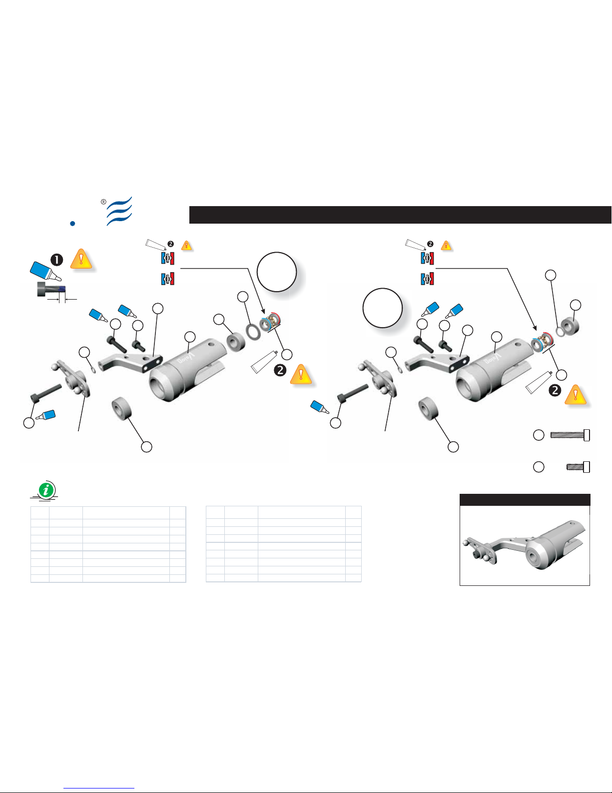
3
2
4
8
1
5
1
6
7
8
Mixing Lever Assy
Large Internal Diameter
always go toward the
main Rotor HUB
Small Internal Diameter
always go toward the Blade
Grease
Grease
Main Rotor Pitch Assy
Ely
Q
3
2
4
8
1
5
Item Code Description Q.ty
1 8601000A Bearing d6, D13, W5 4
2 8202100B Washer d9, D13, W 0.5 2
3 8601300A Thrust bearing d6, D12, W 4.5 2
4 8201300A Flat Was her d3, D5, W 0.5 2
5 8106400A Main Blade Grip Arm V50 Alu 2
6 8106300A Main Blade Grip V50 A lu 2
7 8201800A Socket S crew M3x 8 2
8 8203800A Socket S crew M3x 16 4
Item Code Description Q.ty
1 8601000A Bearing d6, D13, W 5 4
2 8202100A Was her d6, D10, W0.5 2
3 8601300A Thrust bearing d6, D12, W4.5 2
4 8201300A Flat W asher d3, D5, W 0.5 2
5 8106400A Main Blade Grip A rm V50 Alu 2
6 8106300A Main Blade Grip V 50 Alu 2
7 8201800A Sock et Sc rew M3x8 2
8 8203800A Sock et Sc rew M3x16 4
Preview
1
6
7
8
Mixing Lever Assy
S017-2
Large Internal Diameter
always go toward the
main Rotor HUB
Small Internal Diameter
always go toward the Blade
Grease
BAG EQ3014
Grease
AB
B
A
Vision 50 - Competition / Italy 13-05-2009
Glue width: approx. 1mm
Blue
Locktite
Blue
Locktite
Blue
Locktite
Blue
Locktite
7
Socket screw M3x8 (x2)
Blue
Locktite
Blue
Locktite
Blue
Locktite
Socket screw M3x16 (x4)
8
Page 42
Ely
Q
S018-1
EN DE FRIT
(Bag EQ3015-3021)
Main Rotor Head Assy
Make up the assy according to the
drawing.
Add the Main Rotor Hub (6). Insert the
Dumper (18) using white mineral oil in
order to facilitate the operation. Add now
the Spindle (1), and make sure that the
ends come out of the same measure.
Each part identified by the “Locktite”
symbol, must be impregnated with a
small drop of medium seal Locktite (blue).
The Ball Link (12) have an insertion
direction; the symbol must be faced
externally (please see fig. 1).
Assemble the Paddles (21) so that
they are symmetrically equidistant
from the center. Please check that the
insertion edge is clockwise.
(Bag EQ3015-3021)
Main Rotor Head Assy
Eseguire il montaggio seguendo lo schema.
Assemblare il Main Rotor Hub (6).
Posizionare i Dampers (18) utilizzando,
come lubrificante, olio di vaselina affinché
l’operazione di inserimento sia resa più
agevole. Di seguito inserire lo Spindle (1)
cercando di ottenere esternamente una
simmetria delle estremità.
Ogni vite, identificata con il simbolo
“Locktite”, deve essere preventivamente
impregnata di Locktite a tenuta media (blu).
I Ball Link (12) vengono utilizzati rispet-
tando un orientamento; il simbolo (logo
ElyQ) deve essere posizionato verso
l'esterno (vedi fig.1).
Montare i Paddle (21) in modo che
risultino equidistanti, in maniera
simmetrica, dal centro. Verificare che il
bordo di entrata degli stessi sia rivolto
seguendo la rotazione oraria.
(Bag EQ3015-3021)
Main Rotor Head Assy
Führen Sie die Montage nach dem Schema
aus.
Montieren Sie die Gruppe bezüglich der Main
Rotor Hub (6). Setzen Sie die Damper (18)
ein, indem Sie als Schmiermittel Vaselinöl
benutzen, damit der Einsetzvorgang
erleichtert wird. Jetzt setzen Sie die
Blattlagerwelle (Spindel (1)) ein, dass die
Enden gleichmäßig überstehen.
Wo das Symbol “Locktite” angebracht ist,
muss die Komponente mit Locktite
mittelfest (blau) gesichert werden.
Die Ball Link (12) haben eine
Einsetzrichtung; das Symbol muss nach
außen zeigen (siehe Abb.1).
Die Paddel (21) so montieren, dass sie
gleich weit und symmetrisch von der
Mitte entfernt sind. Kontrollieren Sie, dass die
Vorderkante in den Uhrzeigersinn gerichtet
ist.
(Bag EQ3015-3021)
Main Rotor Head Assy
Exécuter le montage en suivant le schéma.
Monter le groupe relatif au Main Rotor
Hub (6). Introduire les Damper (18) en
utilisant, comme lubrifiant, de l'huile de
vaseline afin que l'opération d'insertion soit
facilitée. Maintenant introduire le Spindle
(1) et faire en sorte que l'extrémité sorte
de la même mesure.
La où est reporté le symbole
“Locktite”, le composant doit être au
préalable imprégné de Locktite à tenue
moyenne (bleue).
Les Ball Link (12) ont une direction
d'insertion; le symbole doit être
positionné vers l'extérieur (voir fig.1).
Monter les Paddle (21) de façon à ce
qu'ils soient équidistants, en mode
symétrique, du centre. Vérifier que le bord
d'entrée de ceux-ci soit adressé en suivant
la rotation dans le sens horaire.
Main Rotor Head Assy
Vision 50 - Competition / Italy 13-05-2009
BAG EQ3015-21
Page 43
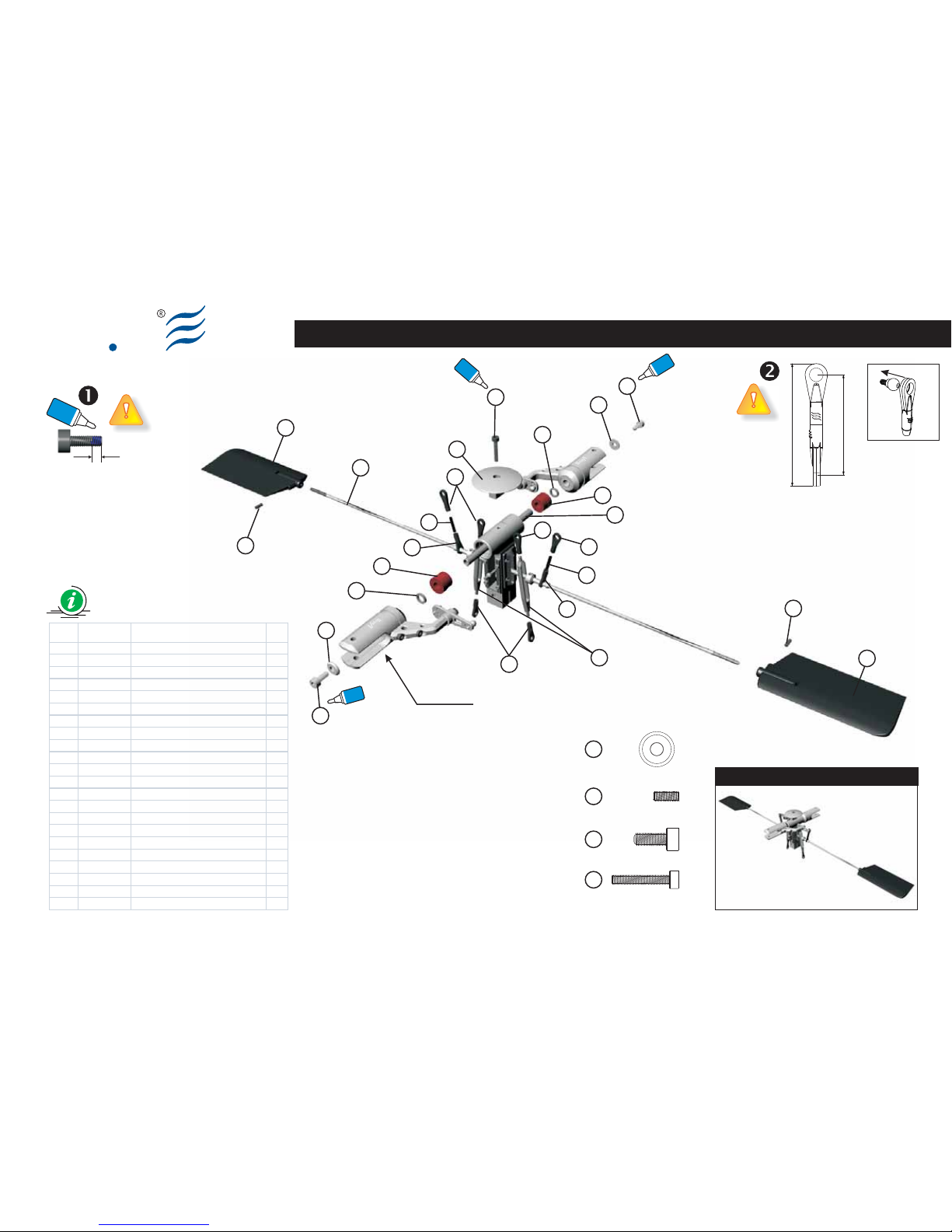
Ely
Q
Main Rotor Head Assy (Part 1.00)
Preview
3
14
14
13
13
12
12
12
12
12
12
18
18
16
16
8
1
2
20
20
21
22
21
Glue width: approx. 1mm
Blue
Locktite
S018-2
Item Code Description Q.ty
1 8100600A Spindle 1
2 8109600B Control Fl yBar (V 50c) 2
3 8204000A Socket s crew M3x 18 1
4 8110200A Control Fl ybar Rod V50c 2
5 8102300B Fly bar see saw lever 0.00 1
6 8109500C Cent er Hub (V50c) 1
7 8010700A Fly bar Guide (V50c) 2
8 8109700A Head Stop (V 50c) 1
9 8009900A Fly Bar SeeSaw Guide (V50c) 2
10 8110400A Fl ybar Collar (d3, D4, W23) 2
11 8103200A Link M2. 3x14 2
12 8002800B B all Link B 8
13 8201400A W asher d4, D11, W1. 7 2
14 8201500A S ocket sc rew M4x10 2
15 8204600A S et sc rew M4x4 1
16 8103100A Fl ap coll ar d6, D9, W 1.5 2
17 8205100A S ocket sc rew M2x4 16
18 8005400A Damper 90° 2
19 8200200A S et sc rew M3x4 2
20 8204300A S et sc rew M3x8 2
21 8005000A 20g P addle 2
22 8105700A Fl ybar 440mm V50 SUS 1
11
11
BAG EQ3015-21
Fig. 1
Vision 50 - Competition / Italy 13-05-2009
Main Rotor Pitch Assy
Blue
Locktite
Blue
Locktite
Blue
Locktite
31.25
38.25
14
Socket Screw M4x10 (x2)
13
Washer d4, D11, W1.7 (x2)
20
Set Screw M3x8 (x2)
Socket Screw M3x18 (x1)
3
Page 44
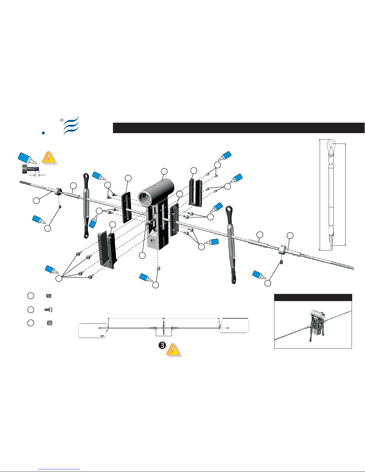
Ely
Q
Main Rotor Head Assy (Part 1.01)
Glue width: approx. 1mm
Blue
Locktite
Blue
Locktite
Blue
Locktite
Blue
Locktite
Blue
Locktite
Blue
Locktite
Blue
Locktite
S018-3 Vision 50 - Competition / Italy 13-05-2009
190.5 190.5
27.5027.50
4
7
7
9
9
6
4
5
10
19
19
15
17
17
17
17
17
17
17
10
Blue
Locktite
Blue
Locktite
Blue
Locktite
Blue
Locktite
90.50
83.55
BAG EQ3015-21
Preview
Socket screw M2x4 (x16)
17
Set Screw M4x4 (x1)
15
Set Screw M3x4 (x2)
10
Page 45
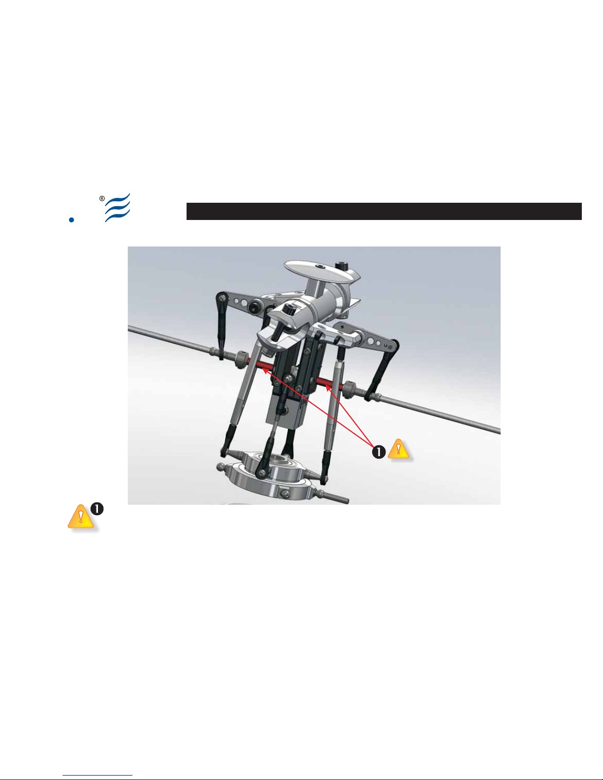
Ely
Q
S018-4 Vision 50 - Competition / Italy 17-07-2009
Flybar Collar
?Non serrare il Flybar Collar tra il Seesaw Lever e il Control Flybar Rod. Importante:
questo componente deve essere libero di ruotare intorno alla flybar.
?Do not tighten the Flybar Collar between Seesaw Lever and Control Flybar Rod.
Important: this component must freely rotate around the flybar.
Ely
Q
Flybar Collar
NOTE
Page 46

Ely
Q
S019-1
EN DE FRIT
(Bag EQ3016)
Swash Plate R0.04 Assy
This set comes assembled from the
factory.
Each part identified by the “Locktite”
symbol, must be impregnated with a
small drop of medium seal Locktite (blue).
(Bag EQ3016)
Swash Plate R0.04 Assy
Questo componente viene fornito già
assemblato.
Ogni vite, identificata con il simbolo
“Locktite”, deve essere
preventivamente impregnata di Locktite
a tenuta media (blu).
(Bag EQ3016)
Swash Plate R0.04 Assy
Dieses Teil wird bereits montiert
geliefert.
Wo das Symbol “Locktite” angebracht
ist, muss die Komponente mit
Locktite mittelfest (blau) gesichert
werden.
(Bag EQ3016)
Swash Plate R0.04 Assy
Cet ensemble est fourni déjà assemblé.
Là où est reporté le symbole
“Locktite”, le composant doit être au
préalable imprégné de Locktite à tenue
moyenne (bleue).
Swash Plate R0.04 Assy
BAG EQ3016
Vision 50 - Competition / Italy 13-05-2009
Page 47
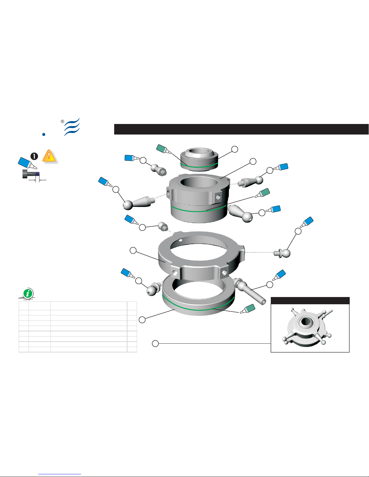
Swash Plate R0.04 Assy
Ely
Q
6
5
4
4
4
7
4
3
3
2
1
Blue
Locktite
Blue
Locktite
Blue
Locktite
Blue
Locktite
Blue
Locktite
Blue
Locktite
3
Blue
Locktite
Preview
Glue width: approx. 1mm
Blue
Locktite
S019-2
8
Item Code Description Q.ty
1 8103900B S wash plat e upper Rel.B 1
2 8104000C Swash plate lower Rel.C 1
3 8104100A B all type B M 3x3 - 3,75 mm 3
4 8104200A B all type C M3x 5.5 - 11 mm 4
5 8104300A B all type D M3x 3 - 20 mm 1
6 8601400A B earing d30, D42, W7 1
7 8601500A Radial sph. plain Bear. d10,D19,w6,W9 1
8 8400900D Swash plate Rel. C ass y
BAG EQ3016
Green
Locktite
Green
Locktite
638
641
638
641
638
641
This set comes assembled
from the factory.
Questo componente viene
fornito già assemblato.
Dieses Teil wird bereits
montiert geliefert.
Cet ensemble est fourni
déjà assemblé.
Blue
Locktite
Green
Locktite
Vision 50 - Competition / Italy 13-05-2009
Page 48

Ely
Q
S020-1
EN DE FRIT
(Bag EQ3017)
Main Rotor HUB & Servo Rear Drive
Make up the assy according to the
drawing.
Each part identified by the “Locktite”
symbol, must be impregnated with a
small drop of medium seal Locktite (blue).
The screws M2x4 (6) must not be
over tighten, because they must
ensure a good seal without over
fastening.
(Bag EQ3017)
Main Rotor HUB & Servo Rear Drive
Eseguire il montaggio seguendo lo
schema.
Ogni vite, identificata con il simbolo
“Locktite”, deve essere
preventivamente impregnata di Locktite
a tenuta media (blu).
Le viti M2x4 (6) non devono essere
serrate in maniera eccessiva. Le
stesse devono assicurare una buona
tenuta ma senza eccedere nel serraggio.
(Bag EQ3017)
Main Rotor HUB & Servo Rear Drive
Führen Sie die Montage nach dem
Schema aus.
Wo das Symbol “Locktite” angebracht
ist, muss die Komponente mit
Locktite mittelfest (blau) gesichert
werden.
Die selbstschneidenden Screw M2x4
(6) müssen einen guten Halt
garantieren, ohne diese zu überdrehen.
(Bag EQ3017)
Main Rotor HUB & Servo Rear Drive
Exécuter le montage en suivant le
schéma.
Là où est reporté le symbole
“Locktite”, le composant doit être au
préalable imprégné de Locktite à tenue
moyenne (bleue).
Les vis M2x4 (6) ne doivent être
excessivement serrées. Celles-ci
doivent assurer une bonne tenue mais
sans excéder dans le serrage.
BAG EQ3017
Vision 50 - Competition / Italy 13-05-2009
Main Rotor HUB & Servo Rear Drive
Page 49
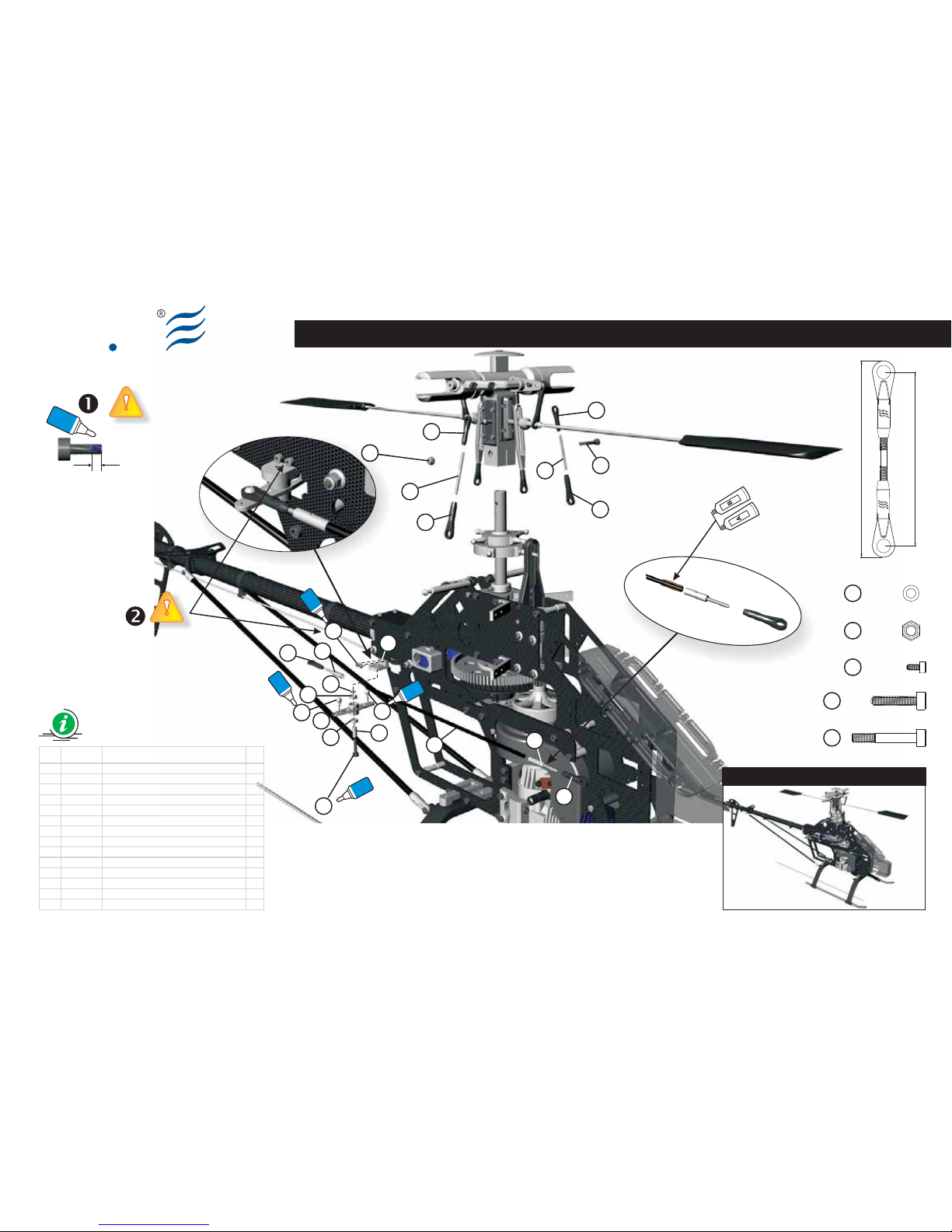
Main Rotor HUB & Servo Rear Drive
Ely
Q
S020-2
Item Code Description Q.ty
1 8110500A Link M 2.3 x 30mm 2
2 8002700B Ball Li nk A 6
3 8200400A Lock nut M3 1
4 8203400A Sock et screw M3x20 (13+ 7) 1
5 8108800A Tail Rotor Bel l Cranck Support (V50c ) 1
6 8205100A Sock et Screw M2x4 2
7 8601100A Bearing d4, D7, W2. 5 2
8 8104400A Ball Type E M2x4 - 2. 75mm 2
9 8101900A Collar (d3, D4, W10) 1
10 8106000A Tail Rotor Bell Crank 1
11 8009300A C.F. Rear Servo Rod d3,D4,W220mm 1
12 8107700A Threaded Coupler M2.3-d4 2
13 8200900A Sock et Screw M3x14 1
14 8201300A Flat W asher d3, D5, W0. 5 1
BAG EQ3017
Preview
Vision 50 - Competition / Italy 13-05-2009
3
4
1
2
2
5
6
8
8
7
7
9
2
2
2
1
10
13
14
11
12
2
12
3
Epoxy
6
Socket screw M2x4 (x2)
Lock Nut M3 (x1)
3
Socket Screw M3x20 (13+7) (x1)
4
13
Socket screw M3x14 (x1)
Flat Washer d3,D5,W0.5 (x1)
14
54.25
61.25
Glue width: approx. 1mm
Blue
Locktite
Blue
Locktite
Blue
Locktite
Blue
Locktite
Blue
Locktite
Check page S025 for your release
Page 50

Ely
Q
S021-1
EN DE FRIT
(Bag EQ3018)
Main Rotor Blades
Make up the assy according to the
drawing.
Add the main blades (not included) so
that the entering edges are in the
clockwise direction. The main rotor spins
clockwise.
Tighten the screws (1) in a way that the
blades oppose a sufficient resistance
both to extension and to closure.
If this is the first R/C helicopter you
assemble, we heartily recommend asking
a skilled pilot for setup help.
In this stage, insert the engine
starter in the Starter Hex Adapter
(please see S005-3, item (1)) and spin
freely the part in order to guarantee the
line up of the system. Tighten the left /
right locking screws of the system
(Engine Mount – please see S004-3
assy).
This operation completes the assembling
phase reported in the scheme S004.
(Bag EQ3018)
Main Rotor Blades
Eseguire il montaggio seguendo lo
schema.
Montare le pale principali (non
incluse) in modo che il bordo di
entrata sia rivolto verso il senso di
rotazione oraria.
Il rotore principale ruota in senso orario.
Serrare le viti (1) in modo che le pale
oppongano una sufficiente resistenza sia
alla distensione che alla chiusura.
Se il Vision 50 è il vostro primo elicottero
R/C che realizzate raccomandiamo
caldamente di farvi aiutare da un pilota
esperto per la messa a punto.
In questa fase inserire l'avviatore del
motore nell'apposito adattatore
esagonale (vedi schema di montaggio
S005-3 posizione (1)) e fate girare senza
avviare affinché venga garantito
l'allineamento dell'intero gruppo
meccanico. Successimante effettuare il
serraggio delle viti che fissano il motore
ai supporti (Engine Mount) destro e
sinistro (vedi schema S004-3).
Questa operazione completa il montaggio
precedentemente effettuato di cui allo
schema S004.
(Bag EQ3018)
Main Rotor Blades
Führen Sie die Montage nach dem
Schema aus.
Montieren Sie die Hauptrotorblätter
(nicht im Lieferumfang) so, dass die
Vorderkante im Uhrzeigersinn ist.
Der Hauptrotor dreht sich im
Uhrzeigersinn.
Ziehen Sie die Schrauben (1) so an, dass
sich die Rotorblätter frei ohne großen
Krafteinwand bewegen können. Sie
werden sich komplett ausdehnen, sobald
der Rotor in Drehung versetzt wird.
Wenn es Ihr erster RC-Hubschrauber ist,
den Sie zusammenbauen, empfehlen wir
Ihnen, sich von einem erfahrenen Piloten
bei der Einstellung helfen zu lassen.
In dieser Phase müssen Sie den
Anlasser des Motors in den dafür
bestimmten Sechskantkonus einsetzen
(siehe Montageschema S005-3 Position
(1)) und lassen Sie das System über den
Anlasser leer laufen, bis die Ausrichtung
der Gruppe garantiert ist.
Ziehen Sie die Befestigungsschrauben
am System (Engine Mount) rechts und
links fest (siehe Schema S004-3).
Dieser Vorgang vollendet die Montage,
die in der Phase durchgeführt wurde, die
Montage nach Schema S004.
(Bag EQ3018)
Main Rotor Blades
Exécuter le montage en suivant le
schéma.
Monter les pales principales (non
incluses) de façon à ce que bord
d'entrée soit dans la direction de rotation
dans le sens des aiguilles d'une montre.
Le rotor principal tourne dans le sens
des aiguilles d'une montre.
Serrer les vis (1) de façon à ce que les
pales opposent une résistance suffisante
à la distension et à la fermeture.
S'il s'agit du premier hélicoptère R/C que
vous réalisez, nous vous conseillons
vivement de vous faire aider par un pilote
expérimenté pour la mise à point.
Dans cette phase introduire le
démarreur du moteur dans le verre
hexagonal prévu à cet effet (voir schéma
de montageS005-3 position (1)) et le
faire tourner à vide afin que soit garanti
l'alignement du groupe.
Effectuer le serrage des vis de fixation au
système (Engine Mount) droit et gauche
(voir schéma S004-3).
Cette opération complète le montage
effectué dans la phase repor tée dans les
schémas S004.
Main Rotor Blades
BAG EQ3018
Vision 50 - Competition / Italy 13-05-2009
Page 51
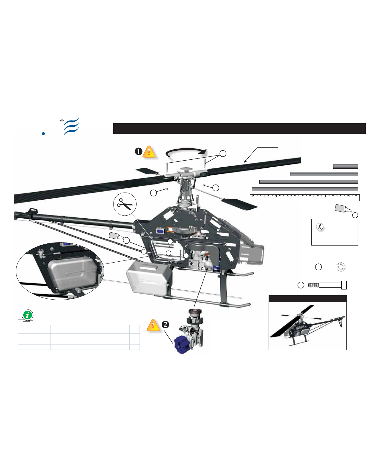
Ely
Q
Main Rotor Blades
S021-2
Preview
Item Code Description Q.ty
1 8203500A Main Grip S ock et Screw M4x 27 (17+10) 2
2 8203100A Lock nut M4 2
3 8010800A Fuel Tank Rubber Seal 500mm (V50c ) 1
1
2
3
2
D
B
A
C
Blades not included
BAG EQ3018
Vision 50 - Competition / Italy 13-05-2009
Socket Screw M4x27 (17+10) (x2)
1
Lock Nut M4 (x2)
2
Cyano
acrylate
3
Cyano
acrylate
A - L = 55mm
B - L = 80mm
C - L = 86mm
D - L = 20mm
A=55mm
D=20mm
B=80mm
C=86mm
01020304050607080
Page 52
Ely
Q
S022-1
EN DE FRIT
(Bag EQ3018)
Servo Installation (Part 01)
Install the servos according to the
drawing. For effective tail control, we
recommend using a suitable good quality
and very fast servo.
Arrange all the links and adjust their
length according to the drawing.
Use Loctite where indicated.
Place the Ball Type E (4) at about 13.5
mm from the center of the servo arm
screw.
Place the Ball Type E (4) at about
19.5 mm from the center of the
servo lever.
Assemble and adjust the Link Rod (C)
length at about 39 mm.
Assemble and adjust the Link Rod (D)
length at about 65 mm.
The Ball Links (5) and (7) have an
insertion direction; the symbol must be
faced upwards (see fig. 1).
If this is the first R/C helicopter you are
assembling, we heartily recommend
asking a skilled pilot for setup help.
(Bag EQ3018)
Servo Installation (Part 01)
Installare i servi seguendo lo schema. Per il
comando di coda si consiglia l'utilizzo di un
servo specificamente progettato e che sia
tale da garantire precisione e velocità.
Preparare tutti i link e regolare le
lunghezze secondo quanto riportato sullo
schema.
Ogni particolare, identificato con il
simbolo “Locktite”, deve essere
preventivamente impregnato di Locktite a
tenuta media (blu).
Posizionare la Ball Type E (4) a circa
13.5mm dal centro della leva del servo.
Posizionare la Ball Type E (4) a circa
19.5mm dal centro dal centro della
leva del servo.
Avvitare fino a raggiungere una
lunghezza del Link Rod (C) di 39mm.
Assemblare e regolare la lunghezza del
Link Rod (D) a 65mm.
I Ball Link (5) e (7) vengono montati
rispettando un orientamento ; il simbolo
(logo ElyQ) deve essere posizionato verso
l'esterno (vedi fig.1).
Se il Vision 50 è il vostro primo elicottero
R/C che assemblate, raccomandiamo
caldamente di farvi assistere da un pilota
esperto per la messa a punto e il
settaggio.
(Bag EQ3018)
Servo Installation (Part 01)
Installieren Sie die Servos nach dem
Schema. Es wird empfohlen, für die
Hecksteuerung ein sehr schnelles Servo
einer guten Marke zu benutzen.
Bereiten Sie die Anlenkgestänge vor und
stelle Sie die Länge, wie auf dem Schema
dargestellt, ein.
Wo das Symbol “Locktite” angegeben
ist, muss jede Komponente mit Locktite
mittelfest (blau) gesichert werden.
Positionieren Sie die Ball Type E (4)
circa 13.5mm von der Mitte des
Servohebels entfernt.
Positionieren Sie die Ball Type E (4)
circa 19.5mm von der Mitte des
Servohebels entfernt.
Die Länge des Link Rod (C) mit 39mm
montieren.
Die Länge des Link Rod (D) mit 65mm
montieren.
Ball Link (5) und (7) haben eine
Einsetzrichtung; das Symbol muss nach
außen gerichtet sein (s. Abb. 1).
Wenn es sich um Ihren ersten
Hubschrauber R/C handelt, empfehlen wir
Ihnen, sich von einem erfahrenen Piloten
bei der Erprobung und Einstellung helfen zu
lassen.
(Bag EQ3018)
Servo Installation (Part 01)
Installer les dispositifs d'asservissement en
suivant le schéma. Il est conseillé pour la
commande de queue l'utilisation d'un
dispositif d'asservissement de bonne
marque et très rapide.
Préparer tous les link et régler les longueurs
selon ce qui est reporté sur le schéma.
Chaque composant, là où est reporté le
symbole “Locktite”, doit être au préalable
imprégné de Locktite à tenue moyenne
(bleue).
Positionner la Ball Type E (4) à environ
13.5mm du centre du levier du dispositif
d'asservissement.
Positionner la Ball Type E (4) à environ
19.5mm du centre du centre du levier
du dispositif d'asservissement.
Assembler et régler la longueur du Link
Rod (C) à 39mm.
Assembler et régler la longueur du Link
Rod (D) à 65mm.
Ball Link (5) et (7) ont une direction
d'insertion; le symbole doit être positionné
vers l'extérieur (voir fig.1).
S'il s'agit du premier hélicoptère R/C que
vous réalisez, nous vous conseillons
vivement de vous faire aider par un pilote
expérimenté pour la mise à point et le
réglage.
Servo Installation (Part 01.00)
BAG EQ3018
Vision 50 - Competition / Italy 13-05-2009
Page 53
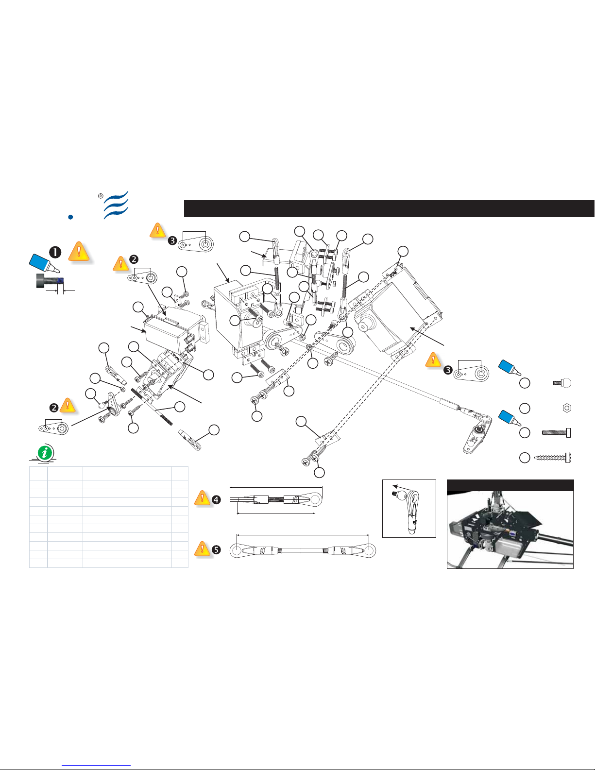
Ely
Q
S022-2
Servo Installation (Part 1.00)
Preview
Link Rod (C) x 3
Link Rod (D) x 1
Item Code Description Q.ty
3 8203000A Nut M2 6
4 8104400A Ball Type E M2x 4 - 2.75 6
5 8101400A Servo Mounting Plate 10
6 8205800A Self Tapping Sc rew 2.5x16 12
7 8002800B Ball Link B 6
8 8104700A Link M2,3 x 19 3
9 8002700B Ball Link A 2
10 8104800A Link M2,3 x 46.5 1
11 8010400A Servo Mount (V50c ) 3
12 8205500A Soc ket Sc rew M2.5x 12 8
BAG EQ3018
Fig. 1
Vision 50 - Competition / Italy 13-07-2009
5
6
5
6
5
7
3
6
6
4
4
3
6
5
5
7
7
3
9
8
8
7
7
8
9
7
12
12
11
11
10
12
12
11
AILERON
PITCH
TAIL
TRHOTTLE
ELEVATOR
13.5
19.5
19.5
13.5
Glue width: approx. 1mm
Blue
Locktite
Self Tapping Screw 2.5x16 (x12)
6
Nut M2 (x6)
3
Ball Type E M2x4 - 2.75 (x6)
4
Socket Screw M2.5x12 (x8)
Blue
Locktite
Blue
Locktite
46.00
39.00
65
Page 54
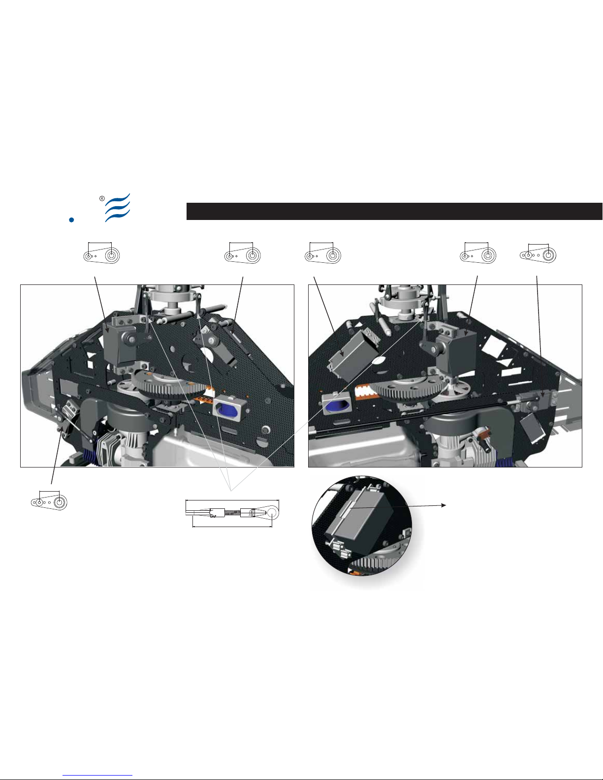
Ely
Q
S022-3
Servo Installation (Part 1.01)
BAG EQ3018
Vision 50 - Competition / Italy 13-05-2009
TAIL
19.5 19.5
13.5
13.5
ELEVATOR
19.5
ELEVATOR
19.5
PITCH
AILERON
TRHOTTLE
46.00
39.00
V
8010400A Servo Mount (V50c)
Page 55

Ely
Q
S022-4 Vision 50 - Competition / Italy 13-05-2009
NOTES:
Page 56

Ely
Q
S023-1
EN DE FRIT
(Bag EQ3019)
Canopy
Make up the assy according to the
drawing.
Based on the canopy version, it could
demand making holes and cuts in order
to obtain a good matching shape.
(Bag EQ3019)
Canopy
Eseguire il montaggio seguendo lo
schema.
In funzione della versione della canopy
quest’ultima potrebbe richiedere dei fori
e dei tagli al fine di ottenere la giusta
sagoma.
(Bag EQ3019)
Canopy
Führen Sie die Montage nach dem
Schema aus.
Aufgrund der Haubenversion könnten
Formlöcher und Einschnitte notwendig
sein, um die richtige Form zu erhalten.
(Bag EQ3019)
Canopy
Exécuter le montage en suivant le
schéma.
En fonction de la version de la canopy,
des trous et des découpages pourraient
être nécessaires afin d'obtenir le juste
gabarit.
Canopy
BAG EQ3019
Vision 50 - Competition / Italy 13-05-2009
Page 57
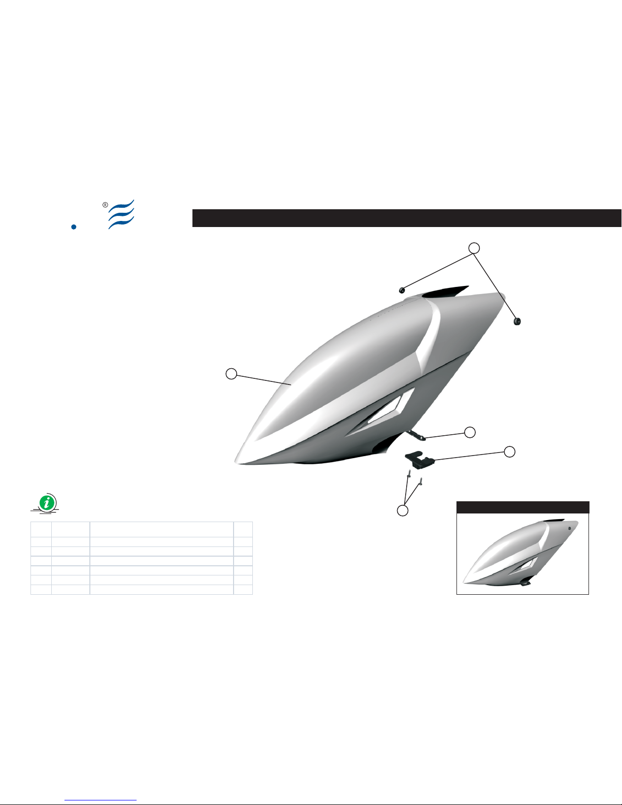
2
3
1
4
Item Code Description Q.ty
1 8003700A Canopy Clip Internal 1
2 8004300A Rubber Grommets 2
3 8003800A Canopy Clip External 1
4 8200000A Self Tapping screw 3x12 2
5 8005900B Canopy Fiber Glass V50 Ultimate (W hite) 1
Preview
Ely
Q
S023-2
5
BAG EQ3019
Vision 50 - Competition / Italy 13-05-2009
Canopy
Page 58
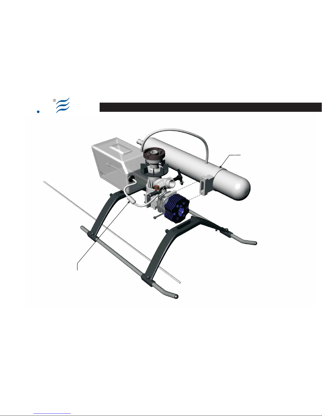
Fuel Tube Settingand Muffler
Ely
Q
S024
Muffler not included
Fuel Filter not included
Vision 50 - Competition / Italy 13-05-2009
Page 59
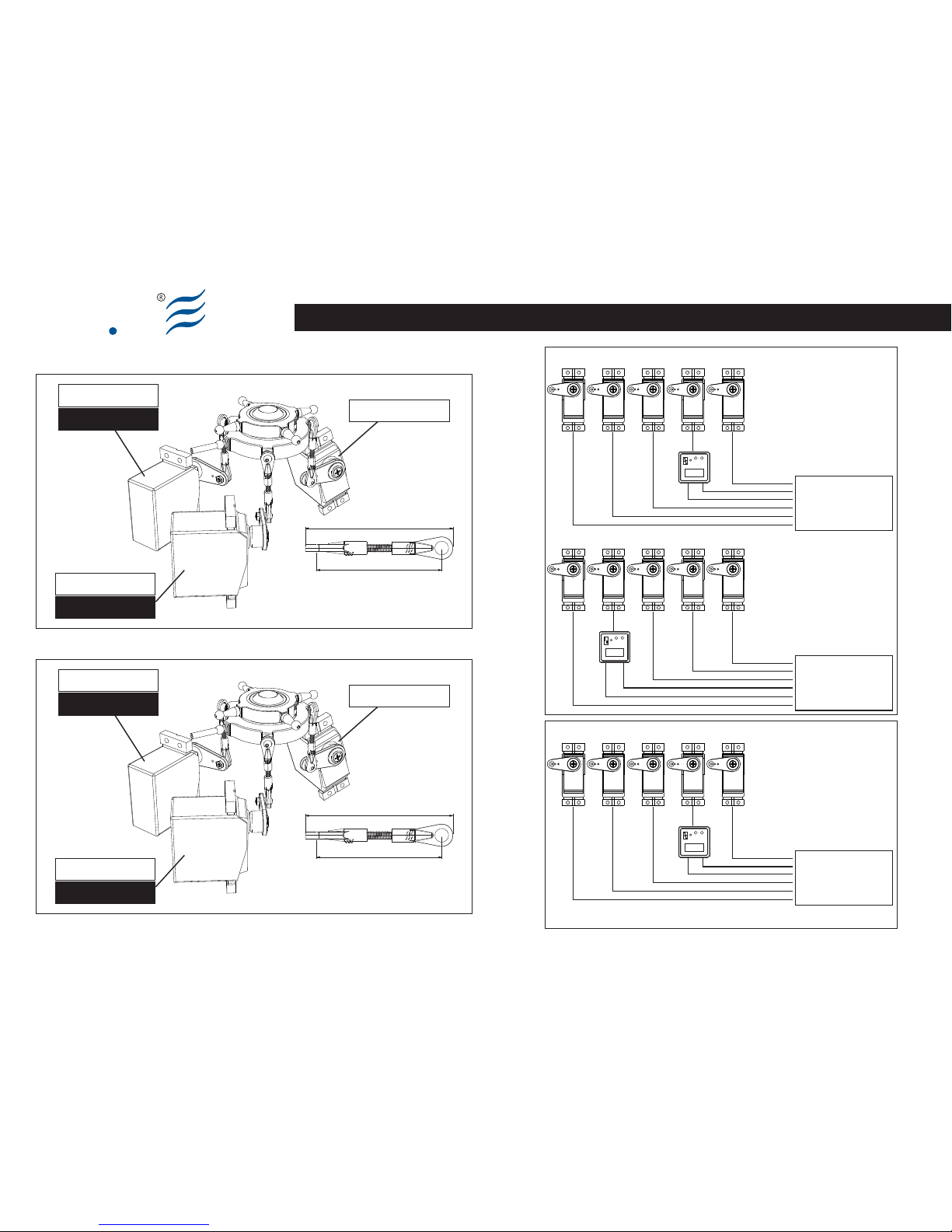
Aileron
Ch1
Elevator
Ch2
Throttle
Ch3
Rudder
Ch4
Pitch
Ch6
Ch1 - Aileron
Ch2 - Elevator
Ch4 - Rudder
Ch3 - Throttle
Ch5 - Gyro Gain
Ch6 - Pitch
Hitec - Futaba RX System
6 channel
GYRO
Throttle
Ch1
Rudder
Ch2 Ch4
Aileron
Ch5
Elevator Pitch
Ch6
Ch1 - Throttle
Ch2 - Rudder
Ch4 - Aileron
Ch3 - Gyro Gain
Ch5 - Elevator
Ch6 - Pitch
Futaba T14 - System
6 channel
GYRO
Throttle
Ch1
Aileron
Ch2 Ch3
Elevator Rudder
Ch4
Pitch
AUX1
Ch1 - Throttle
Ch2 - Aileron
Ch4 - Rudder
Ch3 - Elevator
AUX 2 - Gyro Gain
AUX 1 - Pitch
JR - RX System
7 channel
GYRO
Servo Setting and Adjustment
Ely
Q
AILERON: CH1
AILERON: CH1
ELEVATOR: CH2
PITCH: CH6
PITCH: CH6
Hitec - Futaba
Link Rod (C) x 3
AILERON: CH2
AILERON: CH2
ELEVATOR: CH3
PITCH: CH6
PITCH: CH6
JR
Link Rod (C) x 3
46.00
39.00
Link Rod (C) x 3
46.00
39.00
Page 60
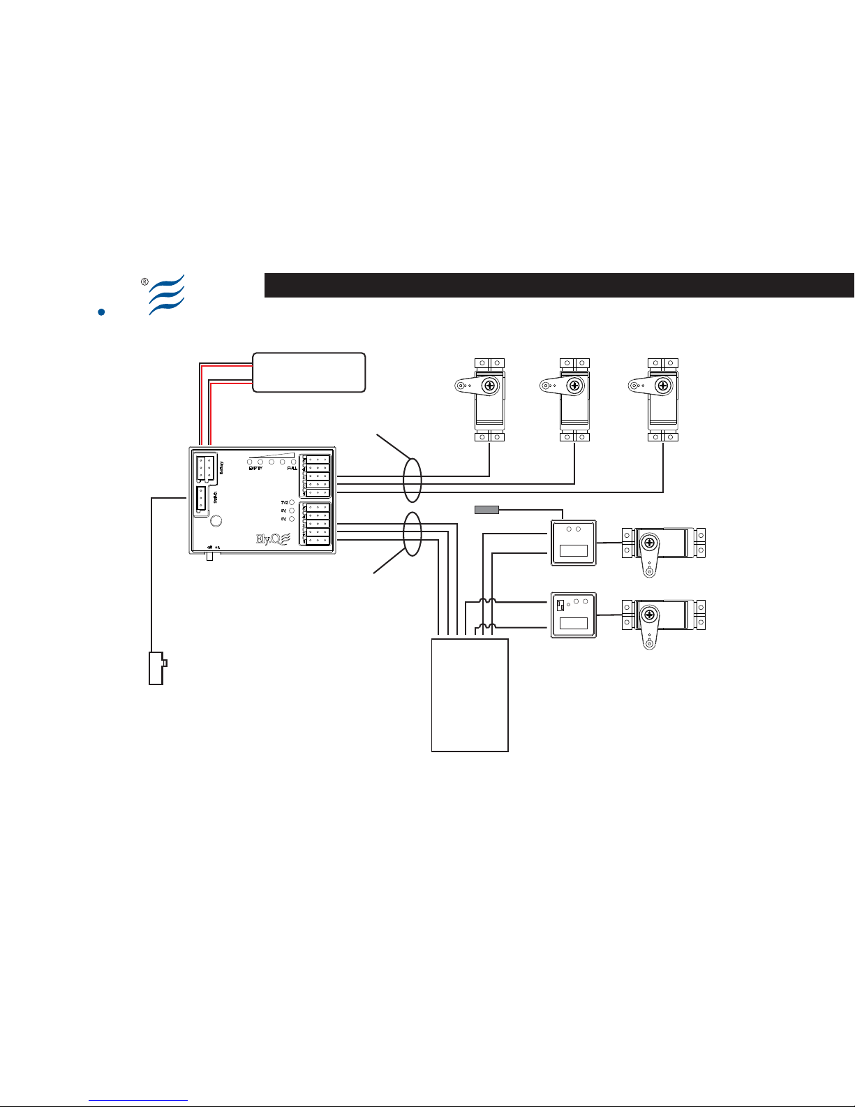
Ely
Q
Vision 50 - Competition / Italy 13-05-2009
GYRO
GOV
Aileron
Ch1
Elevator
Ch2
Rudder
Ch4
Pitch
Ch3
Programmable Output
5V/6V/7.2V/By-Pass
Throttle
Ch6
5V Output
(Fixed)
Battery
LiPo 2s
Remote
Switch
Futaba - 2.4GHz RX System
Ch1 - Aileron
Ch2 - Elevator
Ch4 - Rudder
Ch3 - Pitch
Ch5 - Gyro Gain
Ch6 Throttle -
8 channel
Ch7 - Governor
Ch8 - Aux 1
sensor
Servo Setting and Adjustment
Page 61
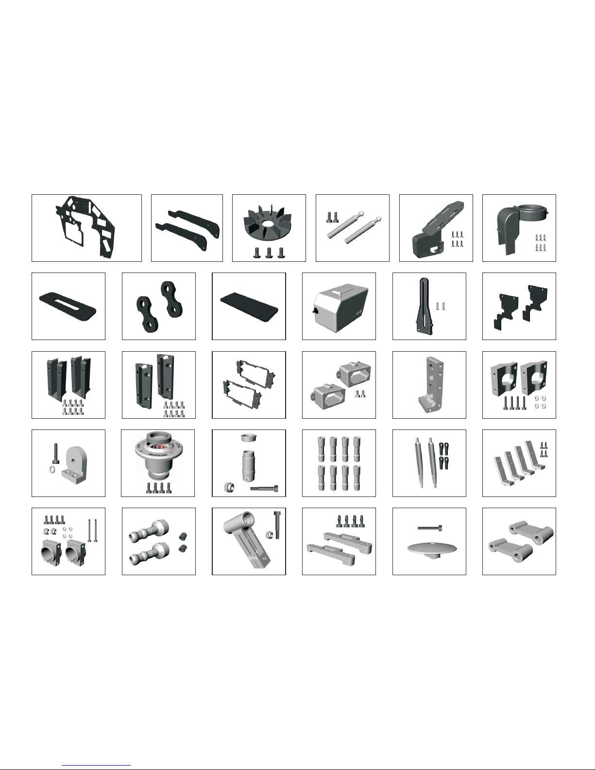
EQ10365 One Way Autor. set (V50c) EQ10366 One Way Autor. Shaft (V50c)
EQ10367 Fan V50c (Carbon Reinf.)
Spare Parts
EQ30004 Main Frame 2mm (V50c)C.F.
EQ30005 C.F. Side Plate (V50c)Set 2mm
EQ30006 Body Retaining Holders (V50c)
EQ30007 Radio tray (V50c)
EQ30008 Engine Fan Conveyor (V50c)
EQ30009 C.F. Bottom Plate 2mm (V50c)
EQ30010 C.F. Breakout Tab 2mm (V50c)
EQ30011 Gyro Mount 2mm (V50c)C.F. EQ30012 Fuel Tank (V50c) EQ30013 Anti Rotation Bracket (V50c)
EQ30014 C.F. Support Frame 2mm (V50c)
EQ30015 FlyBar SeeSaw Guide (V50c)
EQ30016 Flybar Guide Set. (V50c)
EQ30017 Servo Mount (V50c)
EQ30018 Tail Pulley Housing Set (V50c)
EQ30019 Motor Mount (V50c)Central EQ30020 Motor Mount Side Set (V50c)
EQ30021 Tail Rotor Bell Cranck Support (V50c)
EQ30022 26 mm spacer (V50c) EQ30023 Control FlyBar Set (V50c) EQ30024 Servo Mount Side Set (V50c)
EQ30025 Tail Boom Clamp Set (V50c) EQ30026 Control Flybar Rod Set (V50c) EQ30027 Center Hub (V50c)
EQ30028 Landing Skid Brace Mount (V50c)
EQ30029 Rotor Head Stop (V50c) EQ30030 Frame Spacer Medium (V50c)
Vision 50 - Competition / Italy 03-09-2009
Page 62
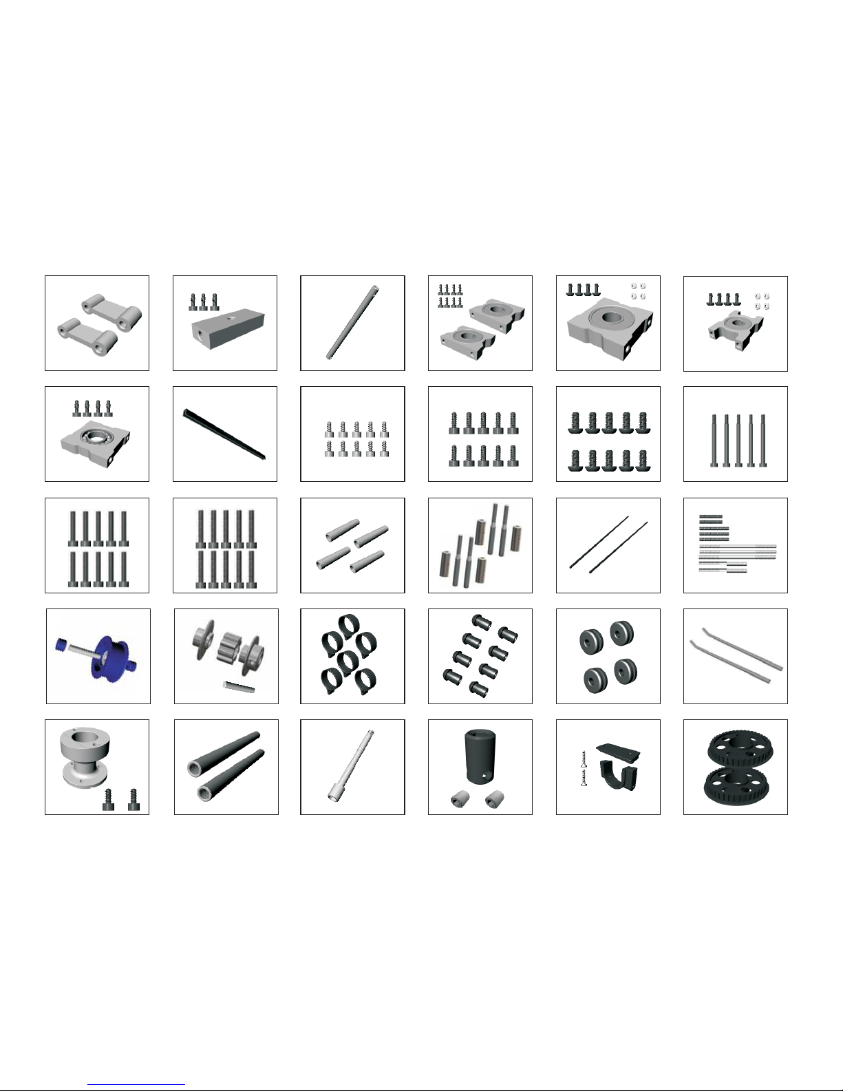
EQ30031 Frame Spacer Smaller (V50c)
Spare Parts
EQ30032 Bottom Reinforcement Block (V50c)
EQ30033 Main Shaft (V50c)
EQ30039 Screw Bag M2x4 (10pcs) EQ30040 Screw Bag M3x6 (10pcs)
EQ30034 Main Rot. Brg Support d10,D22,W6 (V50c)
EQ30041 Button Head Screw Bag M3x8 (10pcs)
M3x8
EQ30042 Screw Bag M3x38 (5pcs)
M3x38
EQ30035 Brg d8,D19,W6 Support (V50c)
EQ30036 Brg d6,D15,W5 Support (V50c)
EQ30037 Brg d9,D17,W4 Support (V50c)
EQ30038 Fuel Tank Rubber Seal (V50c)
M2x4
M3x6
EQ30043 Screw Bag M3x18 (10pcs) EQ30044 Screw Bag M3x22 (10pcs) EQ30045 Flybar Collar (d3,D4,W21)
M3x18
M3x22
EQ30047 C. F. Rear Servo Rod d3,D4,L220mm
EQ0038-UP Stabilazer Fin bracket
EQ0021 Guide Pulley Assy EQ0279 Tail Rod Guide
EQ0454B Skid Pipe End Cap EQ0062 Rubber Grommets (Black) EQ0035T Skid pipe set
EQ0143-UP Fan HUB XP3D
EQ0355 SUS Spindle
EQ0360-UP Starter Shaft EQ0361 Starter HEX Adapter
EQ0379 Auto Rotation Pully
EQ10362 Tail Pulley Set (Metal)
EQ30048 Linkage Rod Set (V50u-V50c)
EQ30046 Threaded Coupler M2.3d4,
Vision 50 - Competition / Italy 03-09-2009
Page 63
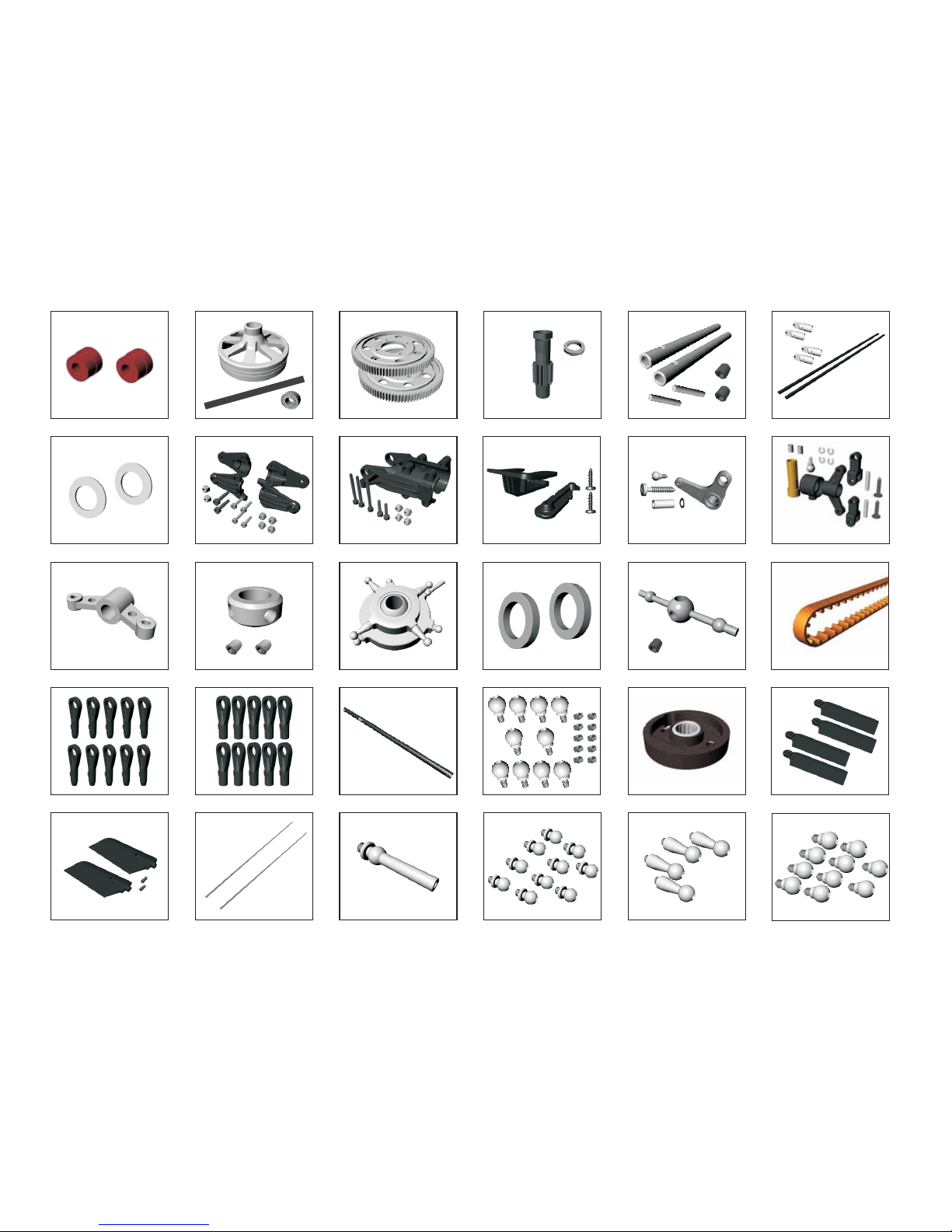
Spare Parts
EQ0382 Flap Dampers 90° (Progressive)
EQ0506-UP Clutch Bell EQ0518 96T Main Spur Gear
EQ0518-P Drive Gear Pinion 11T with Nut
EQ0030 SUS Tail Rotor Shaft
EQ0016 Tail Pitch Control Lever EQ0027-UP Carbon Reinforce Tail Case
EQ0355F Flap Collar
EQ0017 Tail Pitch Slider
EQ0239 Canopy Clip set
EQ0372 Thrust Collar
EQ0148-UP Tail Rotor Grip (Reinforced)
EQ0520 686XL Tail Drive Belt SE (T)
EQ0018-UP Main Shaft Lock Ring EQ1008 Swash Plate Assy EQ1011 Flybar Seesaw Lever
EQ2056-V2 Carbon Tail Boom Brace Set
EQ10368 Tail Pitch Control Fork (Metal)
EQ10361 Tail Boom V50 with Logo (Carbon Fiber)
EQ0041V2 Ball Link A EQ0040 Ball Link BV2
EQ2002 Ball M2 (stainless steel)
EQ68020 Clutch
EQ0037-UP Tail Rotor BladeCarbon Reinforced
EQ0482-UP Carbon Reinforced Paddle 22g.
EQ2001 Antenna Tube
EQ2003 Ball M3 L=20 (stainless steel)
EQ2004 Ball M3 (stainless steel) EQ2005 Ball M3 L=11 (stainless steel) EQ2006 Ball SelfTapp.( stainless steel)
Vision 50 - Competition / Italy 03-09-2009
Page 64
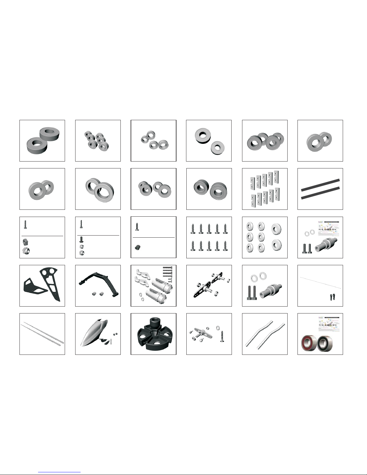
EQ10370 Angular Bearing d5, D10, W4
EQ2010 Main Shaft Brg d10, D22, W6
EQ2011 Bearing d3, D6, W2.5
EQ0054 Servo Mounting Plate
EQ2016 Bearing d6, D10, W3 EQ2017 Bearing d5, D10, W4
EQ2018 Bearing d5, D11, W5
EQ2054 Washer Bag
M2.5x8
M2.5x16
M3x20S
M4x8
M4x10
M4x25S
M3x6
Lock Nut M2.5
Lock Nut M4
M3x8
M3x14
M3x16
M3x20
M3x25
M3x30
Nut M2
Lock Nut M3
EQ2050 Screw Bag (10pcs each) EQ2051 Screw Bag (5pcs each) EQ2052 Screw Bag (10pcs each)
2x8
2x10
3x12
3x18
M3x4
M3x8
M3x18.5
M4x4
EQ2053 Screw Selftapping 2.6x12
EQ2012 Bearing d4, D7, W2.5
EQ2013 Starter Brg d8,D19,W6-d6,D15,W5
EQ2015 Thrust Bearing d6,D12,W4.5 EQ2014 Bearing d6, D13, W5
EQ63006 Clutch Liner HD Pro
EQ2015-T Thrust Bearing d5,D10,W4
Spare Parts Vision 50 - Competition / Italy 03-09-2009
EQ2072 Fiber Glass Canopy V50 White
EQ2081 Carbon Fiber Tail Fin
EQ2075 3D - Landing Skid Structure Set
EQ2077 Mixing Lever (Metal)
EQ2076 Main Rotor Pitch Housing (Metal)
EQ1018-L SUS Rear Servo Rod L=620
EQ Flaybar Rod (440mm)61008
EQ10356 Liner Mount Tool
EQ2071 Tail Rotor Bell Crank (Metal)
EQ2059 Sil. Tube Long Life (Fuel tank)
EQ10364 SUS Tail Rotor Hub V2
EQ10371 SUS Tail Rotor Hub for Angular brg.
Page 65
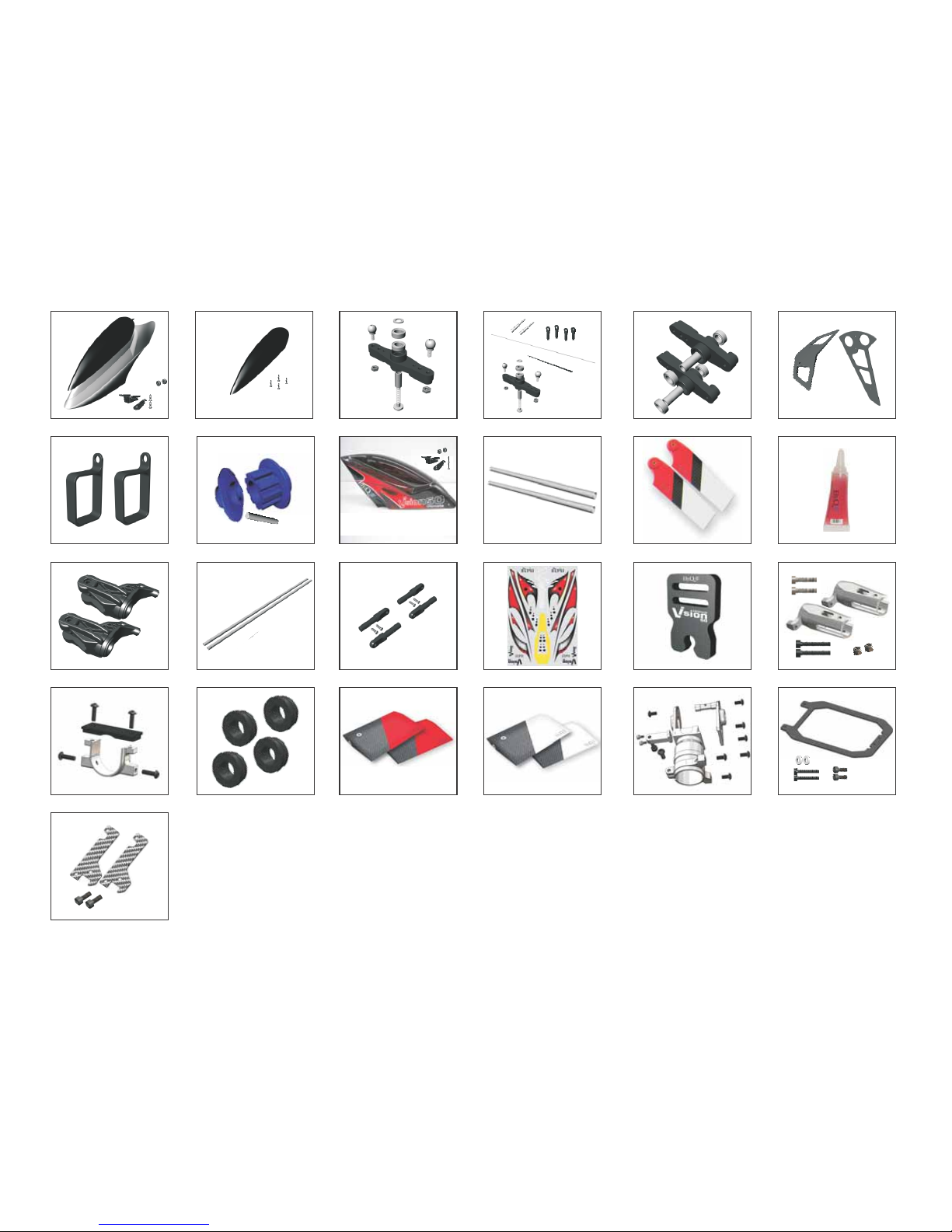
Spare Parts Vision 50 - Competition / Italy 17-10-2009
EQ2055 Plastic Canopy V50 EQ2074 Plastic Canopy Cover V50
EQ2071-P Tail Rotor Bell Crank (Plastic)
EQ2058-P Front Servo Tail Set (Plastic)
EQ2073 Canopy Fiber Glass V50 painted (SET)
EQ10357 One Way Bearing Grease
EQ10360 3D Decal Vision 50 Ultimate
EQ10363 Tail Rotor Blade (Red Devil)C.F.
EQ0029 Tail Pulley Set
EQ0312 Header Tank Spare Bracket
EQ0038 Carbon Reinforced Tail Fin
EQ1020 Mixing Lever
EQ0521 Tail Boom (T)
EQ1006 Main Rotor Pitch Housing
EQ0329-01 Tail Support Rod End
EQ10369 Tail Rotor Grip Set (Metal) EQ0329-00 Tail Support (T)
EQ10355 Blade Holder (Vision 50)
EQ10372 Stabilizer Fin Bracket Set (Metal)
EQ10373 Fuel Tank Grommets (Black)
EQ10375 C.F. Flybar Paddle 17gr (V50)
EQ10374 C.F. Flybar Paddle 12gr (V50)
EQ30051 C.F. Bottom Frame (V50c)
EQ30052 C.F. Frame Brace Set (V50c)
EQ30049 Metal Tail Belt unit (V50)
Page 66
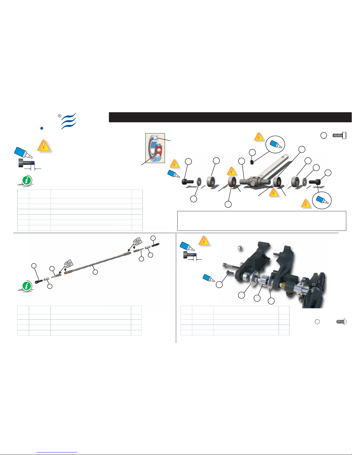
Epoxy
Epoxy
1
1
3
3
2
2
4
Ely
Q
Vision 50 - Competition / Italy 25-10-2009
Vision 50c 1.01 Version
Red side
Red side
Black side
Black side
Controllare l’ orientamento degli Angular Bearing durante l’assemblaggio. Assicurarsi che il lato identificato dal colore nero sia rivolto verso le
pale di coda. Se si inverte il senso di inserimeto si avrà la rottura di tutto il sistema.
Pay special attention to Angular Bearing inserting direction during the assembling process. Make sure side marked with black colour is
oriented towards tail blades. Should you invert inserting direction this will lead to the whole structure break.
Warning:
Glue width: approx. 1mm
Glue width: approx. 1mm
Blue
Locktite
Blue
Locktite
Blue
Locktite
Blue
Locktite
Blue
Locktite
Blue
Locktite
1
1
4
1
2
2
2
3
3
3
4
4
5
6
Item Code Description Q.ty
1 8201800A Socket Screw M3 x 8 2
2 8205900A Flat Was her d5, D8, W0. 5 2
3 8602600A Angular B earing d5, D10, W4 2
4 8600300A Bearing d3, D10, W 4 2
5 8100900D Tail Rot or Hub 1
6 8200200A Set Screw - M3 x 4 1
Item Code Description Q.ty
1 8002700A Ball Link A 2
2 8107700B Coupler d4 2
3 8112700A Link M2.3-M3 2
4 8009300A C.F. Rear Servo Rod d3,D4, W220m m 1
Item Code Description Q.ty
1 8107900B Tail Pulley Flange Right (Metal) 1
2 8107500B Tail Pulley (Metal) 1
3 8107400B Tail Pulley Flange (Met al) 1
4 8202400A Socket B utton Head Screw M3x6 1
Red side
Black side
Angular Bearing
S025
1
Socket screw M3x8 (x2)
4
Socket button head screw M3x6 (x1)
Page 67

Ely
Q
Vision 50 - Competition / Italy 03-08-2009
Vision 50c 1.01 Version
Page 68

HEADQUARTERS
Strada di Oselin, 39 - Remanzacco (UD) / ITALY
Tel. +39 (0432) 66.70.35 r.a.
Fax +39 (0432) 64.93.78
Http://www.elyq.com e-mail:
CHINA
G/F shop 1. no.30 Ha Heung Road Tok
Wawan, Kowloon
Shenzhen - China
www.elyq.com
Company Certified With the Standards
UNI EN ISO 9001: 2000 (Quality)
Azienda Certificata
UNI EN ISO 9001:2000 (Qualità)
Ely
Q
NOTE:
Additional information on this product and answers to
frequently asked question can be found at our Customer
Support Website.
Printed in China
HINWEIS:
Zusätzliche Informationen über dieses Produkt und
Antworten auf häufig gestellte Fragen finden Sie in
unserem Customer Support-Website.
Gedruckt in China
NOTE:
Des informations complémentaires sur ce produit et des
réponses à des questions fréquemment posées sont
disponibles sur notre site Web d’assistance client.
Printed in China
NOTA:
Ulteriri informazioni su questo prodotto e risposte alle
domande più comuni sono reperibili sul nostro sito Web
di Assistenza tecnica.
Stampato in China
 Loading...