

Elwa HOTRUN-VE 38VE, HOTRUN-VE 48VE, HOTRUN-VE 60VE, HOTRUN-VE 75VE, HOTRUN-VE 96VE Operating And Installation Instructions
Page 1
Page 2

Contents
General information and safety instructions ……………………………… 3
Mounting instructions ……………………………… 4
Water connections ……………………………… 5
Electrical connection ……………………………… 6
Electrical schematics ……………………………… 7
Control panel ……………………………… 8
Legionella cleaning cycle ……………………………… 9
Maintenance ……………………………… 10
Troubleshooting ……………………………… 10
Terms of warranty ……………………………… 14
Flexible connections ……………………………… 15
Approvals:
IEC/AS/NZS 60335.2.35, Electrical safety, Certificate number 11422CA
AS/NZS 3498 and AS/NZS 3500, Watermark, Certificate number 40034
Page 3

3
General information
Thank you for choosing an ELWA digital controlled instantaneous water heater.
To ensure your own safety and that of others you need to read these installation and
operating instructions before using this water heater for the first time.
Please keep the instructions and other documentation close to the unit for future reference
Failure to observe this instruction may lead to damage to the water heater.
This product should not be disposed of. ELWA water heaters can always be serviced or repaired
if needed. To prevent possible harm to the environment or human health from uncontrolled waste
disposal, recycle it responsibly to promote the sustainable reuse of material resources.
Plumbing and electrical installation work, commissioning and maintenance of this appliance
should only be undertaken by a qualified tradesperson. Correct and reliable operation of this unit
will only be ensured if original ELWA accessories are used.
This water heater must be connected to a reliable earth connection at all times.
The electrical resistance of the water must be at least >1300 Ω/cm².
Your water supply-company can inform you about the electrical resistance (specific resistance) of
the water in your area. The water heater should not be installed in an area exposed to the risk of
freezing.
Do not operate a HOTRUN in a “dry state”. The electrical power should remain switched
off until the HOTRUN is completely filled with water and all air is released from the
system!
If the supply cord is damaged, it must be replaced by the manufacturer, its service agent or
similarly qualified persons with an original approved cord in order to avoid a hazard.
This water heater is manufactured in accordance with applicable safety standards and has been
tested by the relevant authorities. It has been certified to comply with AU and EU standards and
the IEC declaration of electromagnetic conformity.
The exact technical specifications of every water heater is shown on the label of the water heater
This appliance is not intended to be programmed by persons (including children) with reduced
physical, sensory or mental capabilities, or lack of experience and knowledge, unless they have
been given supervision or instruction concerning use of the appliance by a person responsible for
their safety.
Accessories supplied with every ELWA HOTRUN water heater: wall plugs and screws, two
flexible hoses Watermark approved for hot and cold water connections, three white blanking
grommets
Page 4

4
The ELWA HOTRUN electric instantaneous water heaters are designed for both point of use
(most efficient and lowest water and energy consumption) and multipoint applications, such as
hand wash basin/shower/kitchen sink(s), in fact all places where instant hot water is required.
The heating of the water is started instantly when sufficient flow is detected by opening a tap or
valve connected to the hot water outlet.
The outlet water temperature depends on the following factors:
- The flow rate through the HOTRUN that is limited by a flow restrictor in the cold water
inlet fitting or if removed can be controlled by a flow valve on the cold water inlet side
- How far the hot water tap is actually opened (or the incoming flow into the HOTRUN
restricted)
- The temperature of incoming cold water
- The mixing of hot- and cold water
The hot water temperature can rise while reducing the flow rate. By closing the hot water tap or
when the flow drops below a minimum flow rate, the heating of the water will stop automatically.
The capacity/performance of the HOTRUN depends on its electrical capacity (kWatt rating).
A temperature rise of 25°C to 30°C can be expected with the standard flow restrictor in the cold
water inlet fitting. An inlet temperature of 25°C can increase the performance by 50% compared
to an inlet temperature of 12°C.
Mounting instructions
1. Mark the position of the plugs or screws according to the positional template, allowing
enough space below and above the water heater (200mm) to open the front cover screws
after installation. The HOTRUN models 38 to 96 can be installed in an over-sink and
under-sink position. As standard, the water heater is supplied for under-sink installation.
To mount in an over-sink position rotate the key-hole bracket on the back plate and the
front cover 180°. The models 120 to 240 can only be installed in over-sink position.
2. Mount the unit using the screws supplied using the positional template.
3. Fit the top screw(s) allowing it to protrude approximately 2-3 mm. Slide the bracket onto
the protruding screw(s).
4. Secure the water heater into position with the screw between the hot and cold water
connections
Page 5

5
Water connections
1. The HOTRUN-VE range of products need a cold water supply pressure of at least 60kPa.
This 60kPa pressure must remain under full flow conditions. When connecting the
HOTRUN to a low pressure tank/rainwater system without pressure pump, it is unlikely to
switch on in a reliable manner. If unit is supplied by rain water, water must be filtered
before passing the HOTRUN water heater. The minimum supply pressure needs to be
secured at all times or the HOTRUN can fail to switch on.
The minimum flow rate to operate the HOTRUN-VE models depends on the model:
2. The maximum inlet water pressure needs to be limited to 600kPa. If it is not guaranteed
the pressure will not exceed 600kPa a pressure limiter of 350kPa or 500kPa needs to be
installed in the total cold water supply to the building or the area where the HOTRUN will
be installed.Take water hammer of flick-mixers into consideration that can cause pressure
boosts, when closing fast, of up to 200kPa on top of the inlet water pressure.
3. Make sure that any flow restrictors in shower heads and aerators in tap outlets installed
after the HOTRUN are not too restrictive, kept clean and make sure these cause minimal
back-pressure to enable the HOTRUN to switch on and off. The outlet back-pressure
needs to be less than the cold water inlet supply pressure, as the cold water can be pushed
back to the HOTRUN when mixing cold water to the hot water and cause the HOTRUN to
switch off. Sometimes a pressure limiter in the total cold water supply needs to be
installed to secure proper performance at all times.
4. Connect the incoming & outgoing water pipe-work to the HOTRUN water connectors
only with the flexible hoses that are supplied with each HOTRUN, unless the water
connections come in from the back through the wall. All HOTRUN fittings and flexible
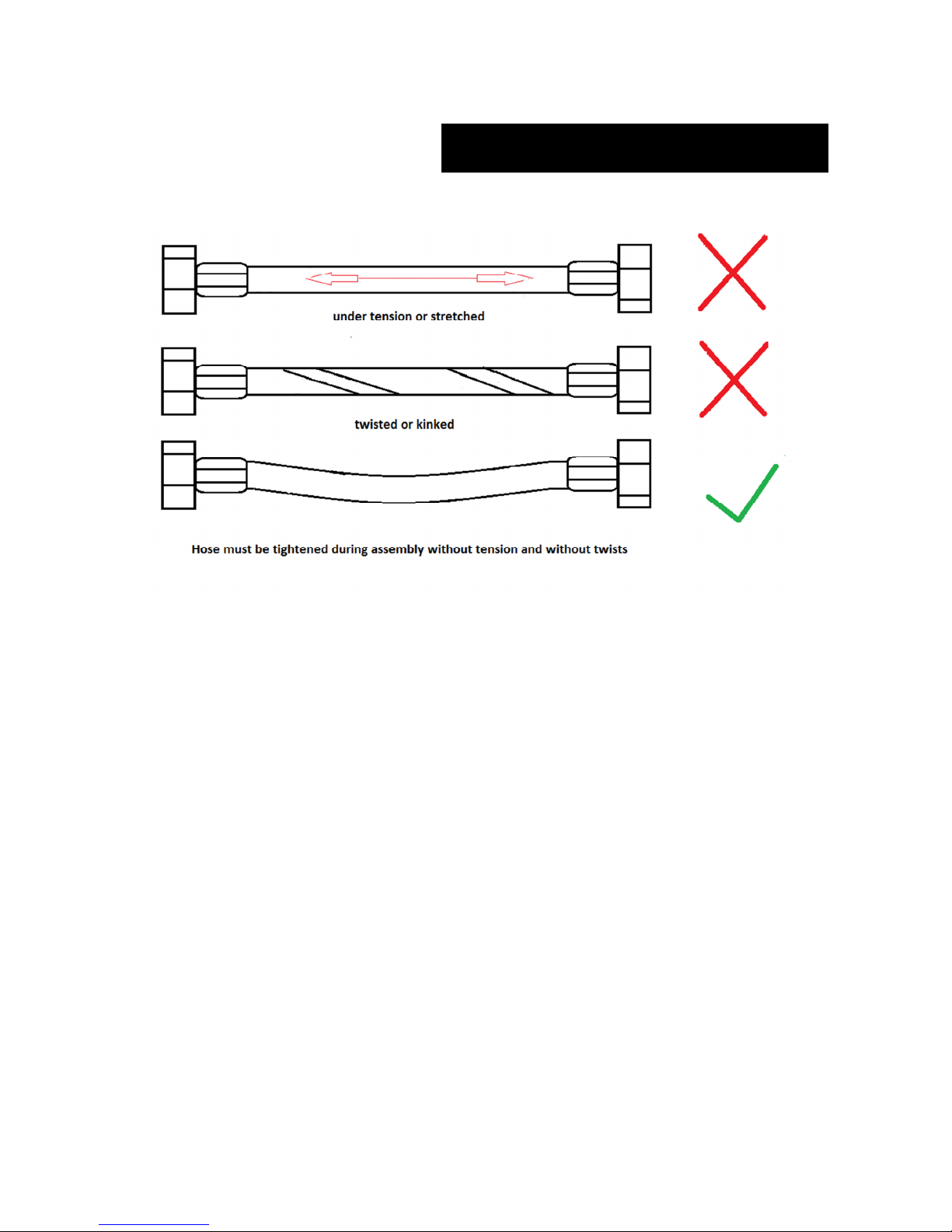
hoses are Watermark approved and have a flat sealing connection. By using the supplied
flexible hoses you will avoid excessive tension on the HOTRUN fittings. Damaging
internal copper pipework during installation is not covered by warranty.
5. The incoming and outgoing water connections for cold and hot water can't be swapped.
The fitting with the blue marking is for the cold water inlet and the one with the red
marking is for the hot water outlet.
6. Always use a ½˝ BSP (100% bore) ball valve on the cold water supply for service
purposes.
7. Important: After installation open the water tap to flush the device to release all air
from the Heat Exchanger and check all connections. Failing to do so shortens the
life-span of the electric elements. Replacement of elements burning out during
installation is not covered by warranty.
HOTRUN MODEL : 38VE 48VE 60VE 75VE 96VE
Min start-up flow rate: 1.5 l/min 1.8 l/min 2.2 l/min 2.9 l/min 3.8 l/min
Standard delivery flow rate: 2.0 l/min 3.0 l/min 4.0 l/min 5.0 l/min 6.0 l/min
Page 6

6
8. There is no need to install an overpressure relief valve.
9. The HOTRUN-VE range water heaters can be programmed to any temperature limit
required. At the time this manual was written only the 50°C limited models for sanitary
fixings for personal hygiene are exempted from the requirement of installing a TMV by
the plumbing code of Australia and as is required by AS3498 for testing and approval of
water heaters in Australia and New Zealand. New legislation is underway to cover this
exemption for all other temperatures.
10. Any set temperature between 35°C and 60°C, as temperature limit, can be programmed
into the water heater by ELWA. This setting can not to be changed by the end user after
installation. Ask for assistance from an ELWA technician if you need to change the
temperature limiter programming.
11. Each water heater is supplied for installation with exposed water and electrical
connections. However, water and electrical connections can also come in from the wall
through the back plate of the water heater (see template for positioning all connections
prior to fitting the unit to the wall). To do so, remove the inlet and outlet water
connections and use the supplied blanking grommets to close of the two holes. Allow for 2
elbows, 1/2" BSP male/female, to connect water to the nuts on the internal copper pipes.
12. The front cover of the model 38 to 96 can be rotated 180° to suit under-sink or over-sink
installation and enable the end user to read the temperatures in the display. The metal keyhole bracket on the back plate can be rotated 180° for this purpose.
Electrical connection
1. Local wiring rules and guidelines must be adhered to.
2. It is necessary to provide a dedicated circuit direct from the switchboard to each
HOTRUN.
3. The HOTRUN has to be connected to an isolator switch to be positioned next to the
water heater.
4. Check insulation resistance and proper earth continuity.
5. Fill the unit with water, and only then, switch the power on.
Attention: Avoid overheating. Fill the unit completely with water before turning on
the mains power supply. For that purpose:
Open the tap and wait until the water flows out from the spout without any air
bubbles.
Close the tap.
Switch-on the mains supply, Activate the HOTRUN on the control panel with on/off
push-button and the HOTRUN is ready to use.
Page 7
7
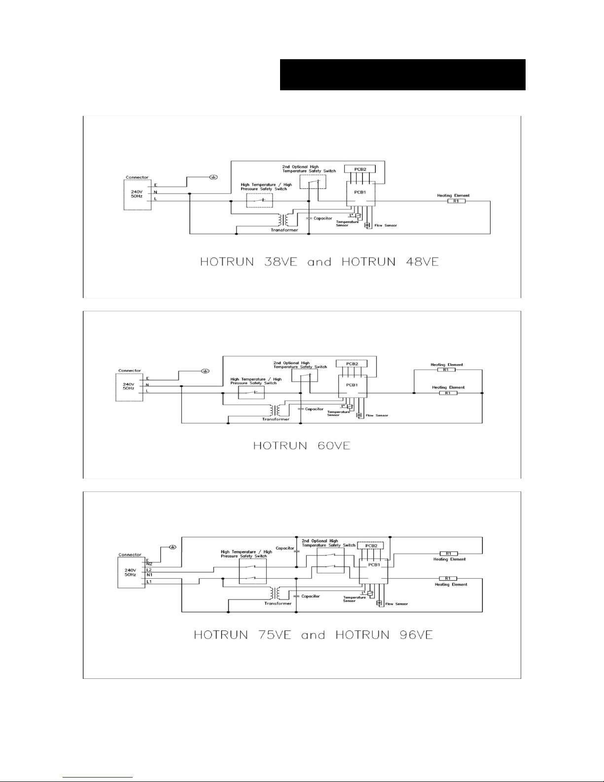
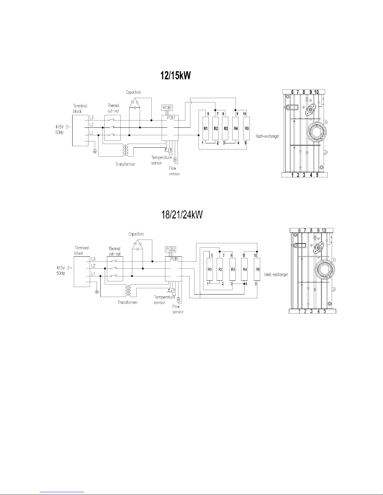
Electrical schematics
Page 8
8
Page 9
9
Operation Of The Control Panel
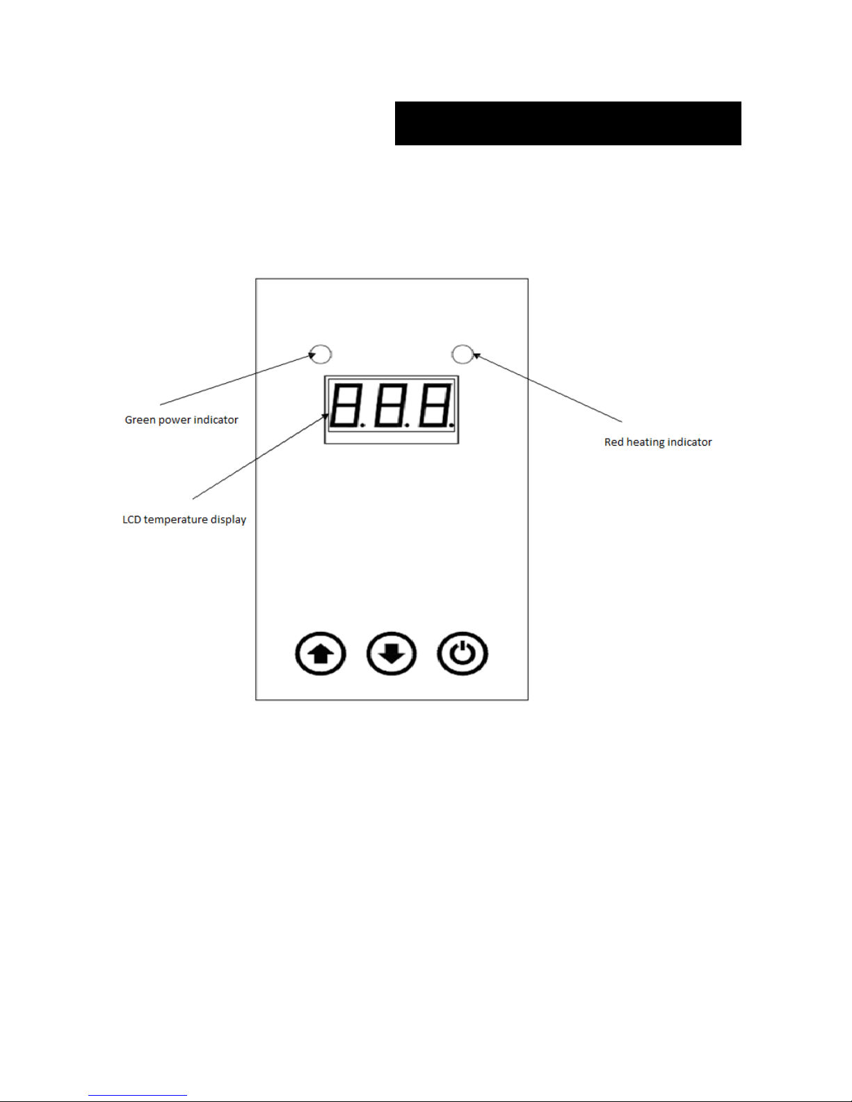
The green light is the power indicator; the red light is a heating indicator.
The LCD display shows the setting or actual water temperature at all times, except during
programming. When activated, it will show the delivery temperature of the water-flow.
Press (↑ or ↓) the key to set the temperature required. To change 1 degree push the buttons for a
short time, a beep confirms every step. To quickly adjust the temperature in 5 degree steps hold
the button pushed in. The red indicator will flash while you set temperature, the display show the
required temperature flashing before reaching set temperature. On initial start-up the temperature
setting will be the maximum delivery temperature programmed and needs to be set to the required
temperature again. The temperature setting can range from 35°C to 60°C. If there is not enough
water flowing through the water heater it will not turn on, the display shows LF (Low Flow). If
the temperature drops below 3°C, the screen will display LL and if over 80°C, it will display OT.
If the inlet water temperature it too high the display will show HH, the water heater will lock
itself out and an alarm will beep.
Page 10

10
Legionella Cleaning Cycle
A service technician can program a HOTRUN-VE model to run through a Legionella Cleaning
Cycle. The purpose of the Legionella Cleaning Cycle is to provide a thermal disinfection of
fixtures downstream of the HOTRUN water heater. A cycle will run for >10 minutes at a
temperature of >60°C as per the current Australian Health Ministers' Regulations and directions
given to ELWA in every State of Australia. ELWA can organise this service for all customers
who have a HOTRUN-VE model installed with models produced from 2015 onwards. During the
Legionella cleaning cycle the display shows the count-down time of the cycle (600 seconds) until
completion, and then remembers all its previous settings for normal operation.
Maintenance
- Due to its advanced design the HOTRUN does not require any maintenance.
- To clean cover, use damp cloth only.
- Scouring and dissolving agents are not suitable.
- Regularly remove debris or scale building up in shower heads and in tap-aerators.
Troubleshooting
Fault Code Most likely cause
F1 Temperature sensor not connected or faulty (reconnect or replace temperature sensor)
F0 Temperature sensor short circuit (replace temperature sensor)
HH Too high inlet or outlet temperature >75°C ± 5°C
LL Inlet water temperature too low < 3°C
LF Inlet water flow too low (can come up for a few seconds during normal start-up)
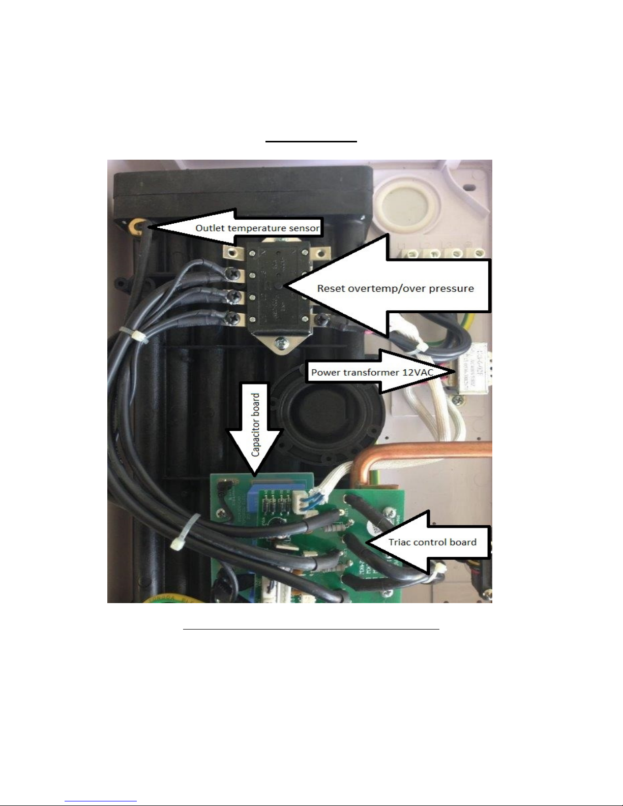
OT Over Temperature/Over Pressure safety switch tripped (reset button)
Initial checks
- Adequate supply and pressure of the water (min. 60kPa).
- Make sure the cold water inlet and the hot water outlet are not connected in reverse.
- The main switch or circuit breaker is switched on.
- The fuse/circuit breaker is not blown / triggered.
- Flow rate from the tap needs to be higher than the minimal flow-rate of the model
installed to activate the heating elements.
Page 11
11
3-phase models:
Heat-exchanger of the 3-phase models 120VE – 240VE
Page 12
12
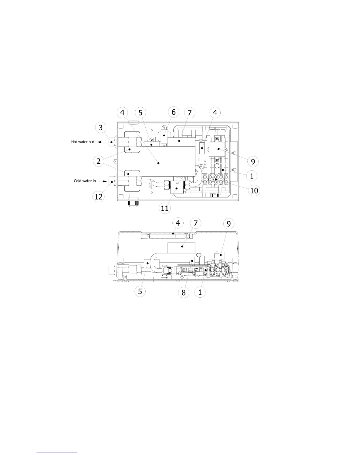
1-and 2-phase models
1. Electric element(s)
2. Rear entry break-outs
3. Hot water outlet
4. Temperature controller
5. Over-temperature safety switch (optional)
6. Transformer
7. Triac power control-board
8. Capacitor PCB
9. Over pressure/over temperature safety
switch
10. Terminal block
11. Inlet water temperature & flow sensor
12. Cold water inlet
Page 13

13
Trouble Shooting Examples
The HOTRUN does not switch on when opening the tap fully.
Causes
- This problem is usually caused by lack of water flow problems. Ensure the pressure on the
cold water supply is over 60kPa, while the HOTRUN is in use and the flow rate is
sufficient to turn the heating elements on.
- Too much back pressure in tap-outlets or shower heads after the HOTRUN, causing lack
of pressure differential over the HOTRUN (back-pressure through the cold)
- Maximum temperature/overpressure cut-out switch is activated. This if most likely due to
air in the HOTRUN not cleared before switching on the electrical supply, or the mains
incoming water pressure is too high.
Remedy
- Fix the water pressure problems; remove any flow restrictions fixtures such as showerheads and tap outlets.
- Switch the electric power supply off; make sure there is no power on any of the terminals
- Check continuity over the safety switch terminals. If there is no continuity over the
contacts, push the reset button on the safety switch.
- Seek electrical assistance to check power supply on all phases and continuity all the way
to the electric elements, and to measure element resistance.
The water that is coming out of the HOTRUN is not warm enough.
Cause
- The incoming water is very cold (below 12°C) and/or the total flow is too high.
Remedy
- A flow restrictor can be installed or an inline (additional) ball valve in the cold water
supply to the HOTRUN can enable the user to reduce the flow and so increase the
temperature to the maximum temperature programmed in the temperature limiter.
The heating of water stops when trying to mix cold water to get the required
outlet temperature
Causes
- Aerator/restrictor in nozzle of outlet causing too much back pressure
- Incorrectly balanced flow restrictor in the supply line, pressure limiter installed in the
wrong place not reducing the pressure of the cold water to the taps
- Pressure and/or flow in the cold supply line is less than the required minimum pressure for
the HOTRUN to switch on.
Remedy
- Remove the restrictions in the tap-aerator or shower-head.
- Check all other taps or restrictors built into the supply line are not affecting the flow or
reducing the pressure too much.
Page 14

14
A HOTRUN fitted in an upper floor situation of a building that is gravity fed,
the HOTRUN doesn’t switch on.
Cause
- The pressure is less than 60 kPa. The pressure of water under gravity is 9 kPa per metre,
this equates to approximately 30 kPa per floor plus the height of the roof tank.
Remedy
- Remove all restrictors in the tap or aerator and use ‘star’ inserts in spout instead of aerator.
Allowing full flow will often help in low pressure situations. Additionally if needed the
flow-controller that is fitted in the cold water inlet fitting of the HOTRUN can be
removed.
If the tests above indicate a fault then contact ELWA Technical Support
Warranty
On the provision that the installation instructions have been followed, ELWA gives a warranty of
twelve months onsite service in Australia and/or 2 years return and repair service. The warranty
starts at the date of purchase as per the invoice.
If despite our extensive products control complaints arise, you should inform your installer first to
make sure the power and water supply to the water heater are fine.
Your installer can call the ELWA service department when on site if any questions arise.
Before you contact the installer, we advise you to read the directions for use.
You can avoid needless discomfort and possible costs.
You can also read our service manual (online on www.elwa.com.au)
If you or your installer can't fix the problem fill in a service request form on our website
www.elwa.com.au/customerservice
Warranty terms:
1. The warranty is valid only on presenting an original invoice, mentioning the date of
purchase, the name of the supplier/installer and the model number of the heater.
2. ELWA may void the warranty if the invoice is not legible.
3. If the barcode or serial number is missing, the warranty will be voided.
4. The warranty will be voided from the moment the appliance has been tampered with
or has been modified in any way.
5. Damage caused as a result of improper use, or faulty installations are not covered by
this warranty.
6. Incorrect installation or maintenance issues such as blocked filters in aerators or flow
restrictors and too low or too high water supply pressure are not warrantable items and
may result in a charge from ELWA or the contractor responsible for the service call
out service.
7. Warranty can be voided if the supplied flexible hoses are not used for exposed water
connections or when too much force was used on the water connections and that has
damaged the copper pipes inside the water heater.
Page 15
15
Flexible connections
This manual has been made with care.
ELWA remains the right to adjust products in the future for various reasons.
Page 16
16
ELWA Pty Ltd ELWA Ltd ELWA BV
Adelaide
Australia
New Zealand
Phone: +61(0) 8 8353 4040
www.elwa.com.au
Auckland
New Zealand
Amsterdam
The Netherlands
Phone: +31 (0)20 436 1224
www.elwa.nl
Ref.02/201606
 Loading...