

Page 1

69
The ZN10 operator integrates perfectly with the design of any up and over door without essentially altering its appearance. It also features quiet and linear operation
which renders it safe and agreeable to use, thanks not least to a courtesy light timed
to switch off after 3 minutes.
Total safety
The use of low voltage motors (12 V) eliminates any risk of electrical discharges or
accidental electrification of the structure.
Electronic clutch
if the door is obstructed by an obstacle, an electronic device will immediately stop
the automatic system as soon as the slightest hint of abnormal friction is detected,
and reverse the movement by about 10 cm.
Easy to install
Simpler electrical installation thanks to the separate control unit, optimizing maintenance and assembly (can be connected to the power supply using an existing socket). The control unit lights up automatically (when the motor is activated) and has a
button for opening and closing the door. The absence of any “control head” at the
end of the mechanism, and consequently the reduction in length of 310 mm, is especially advantageous in situations where space may be limited.
Maintenance-free and reliable
With the new operating principle of a motor travelling along a fixed chain in a track,
the automatic system is quiet and long-lasting, and requires no maintenance.
COMPLETE KIT FOR SECTIONAL DOOR
Type ZKN1
COMPLET KIT FOR SPRING OR COUNTERWEIGHT HORIZONTALLY-PIVOTED DOOR
Type ZKN2
R
R
ZN SERIES ACTUATOR
ZN10 AUTOMATIC SYSTEM FOR SECTIONAL AND SPRING OR COUNTERBALANCE
HORIZONTALLY PIVOTED DOORS
General description
The ZN10 electromechanical operator is
designed for sectional and spring or counterbalance up and over doors.
Thanks to its push-pull and closing force,
650N, it will open and close doors up to 10 m
2
max without difficulty. This generation of
operators is designed with the accent on ease
of installation but also on the strength of the
materials employed.
OVERALL DIMENSIONS
Mod. ZN10
- Electromechanical operator:
- Control unit
Mod. ZN20
116
270
140
135
80
125
270
2600
1600
75
35
1600
70
30
500
250
250
120
- Jointed C-track
- Overall length: 3230 mm
- Dimensions of pack:
ZN10 motor unit: 160x160x800 mm
Tracks: 160x55x1600 mm
Page 2
70
ZN SERIES ACTUATOR
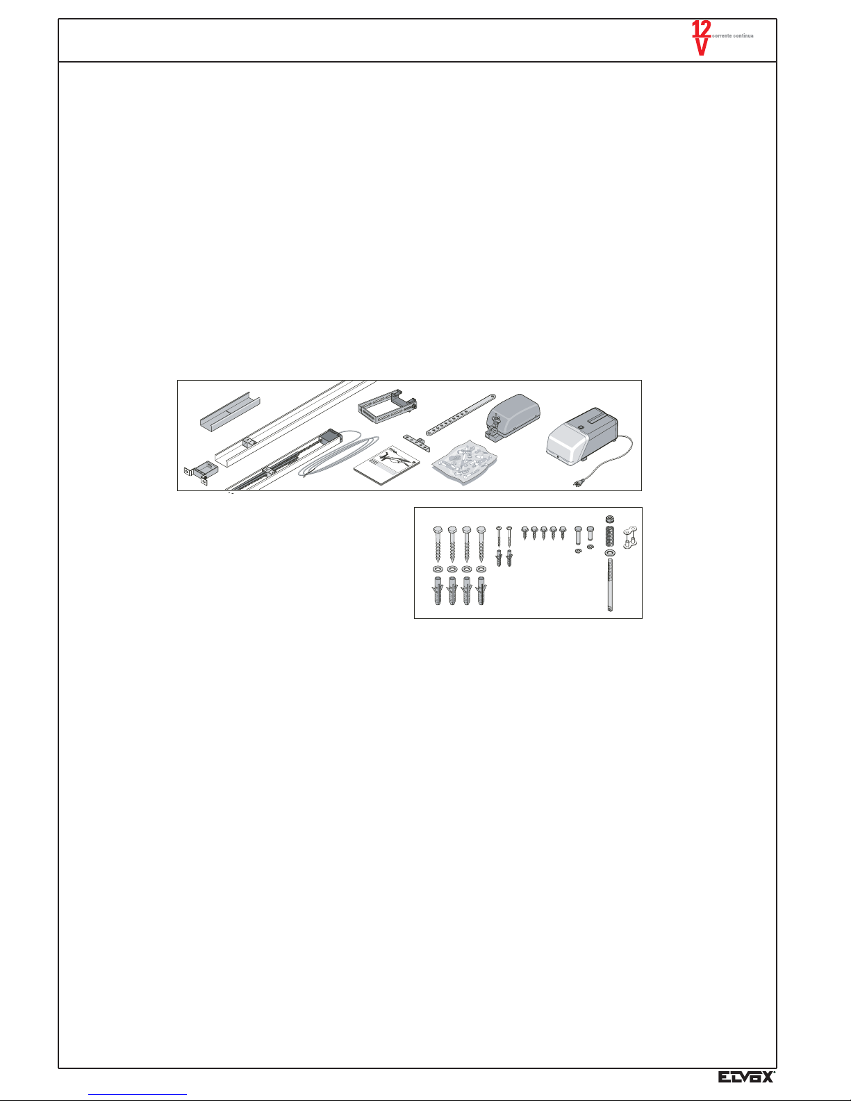
PACKAGING CHECK-LIST
The ZN10 operator does not cause particular handling problems during transport.
The standard version must be combined with the 2600 mm guide (working stroke of motor), type ZN20. The two components are
packed in small cardboard boxes. They must be stored in a dry area that is protected from the weather.
Contents of article ZN10 (Fig. A).
- No. 1 control unit with electronic card and 433 MHz receiver
- No. 1 electromechanical operator
- No. 1 longitudinal rod and door corner fitting
- No. 1 front bracket supporting the track
- No. 1 ceiling suspension bracket for the track
- No. 1 instruction manual
- No. 2 remote controls Type ZT03
Contents of article ZN20 (Fig. A).
- No. 2 C-tracks length 1600 mm.
- No. 2 sliding limit switches
- No. 1 chain with chain raceway
- No. 1 snap-on component with cable for connections to the control unit (6900 mm)
- No. 1 connector for the two C-tracks
- No. 1 ceiling suspension bracket
- No. 1 bag containing material required for assembly.
Assembly material in the bag (Fig. B)
- No. 4 wood screws 8x60
- No. 4 plugs S10
- No. 5 washers 8.4
- No. 2 wood screws 4x50
- No. 2 plugs S6
- No. 5 hexagonal head screws
for metal plate, 6.5x19
- No. 1 long bolt 10x35
- No. 1 short bolt 10x35
- No. 2 safety clips
- No. 1 self-locking nut M8
- No. 1 suspension spring
- No. 1 fixing pin M8x110
- No. 1 two-component chain-link
Fig. A/ZN
Fig. B/ZN
In addition to Type ZN10-ZN20, the Kit ZKN2
also contains Type ZN21 (curved arm).
Control unit supply voltage 230 (-10% +6%) V A.C.
Nominal frequency 50-60 Hz
Motor 12V D.C.
Rated current 0.7 A
Motor power 150 W
Max. torque. 650 N
Nominal traction force 195 N
Maximum speed 180 mm/s
Power consumption in stand-by ~2N
Relative noise (only automation)
< 75 DBA
Working temperature: -20°C ÷+55°C
Protection level: IP40
Working cycle: 15%
Max. surface area of door: 10m
2
max. height of door (standard version) 2600 mm
Radio receiver 433 MHz
Courtesy light YES (24 V, 21 W bulb)
Weight 16 Kg
Working stroke standard version 2600 mm
TECHNICALTECHNICAL SPECIFICATIONS SHOWN ON DATA PLATE ZN10
Doors with a height exceeding 2600 mm require the addition of an extension Type ZN22 of 1600mm (working stroke 4,200 mm.).
Page 3

71
ZN SERIES ACTUATOR
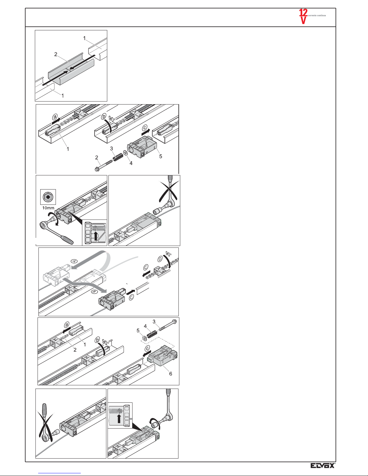
MECHANICAL INSTALLATION
N.B. Choose the desired mounting variation
In case B modify the chain supply voltage.
Fig. 1) Loosen the limit switch (1) on the first track, "end
track", and move it in the direction shown by the
arrow. Open the chain (2) by 180°
Fig. 2) Unlock the motor (1) by pulling the manual release
(N). Insert the chain (2) in the motor so that it
engages with the pinion (3).
Fig. 3) Insert the motor (1) in the "track" (2).
Fig. 1
Fig. 2
Fig. 3
Page 4
72
ZN SERIES ACTUATOR
Fig. 4) Insert the connector joining (2) the two tracks (1). Bring the tracks together until they stop
and lock.
Fig. 5/AC-6/AC-7/AC
On the installation - variation A/C, insert the fixing bracket (a) in
the chain and turn it 90° (b). Insert the terminal head (5) in the
guide (c) , and the washer (4) with spring (3) in the draught dowel
(2). Screw the dowel in the fixing bracket (1). Tighten the chain
until the mark (arrow).
Fig. 5A/B-5B/B-6/B-7/B
On the installation - variation B, invert the supply voltage head.
Insert the fixing bracket (a) in the chain and turn it 90° (b).
Insert the terminal head (6) in the guide (c) and the washer (5)
with spring (4) in the draught dowel (3). Screw the dowel in the
fixing bracket (1).
Tighten the chain until the mark (arrow).
Attention! Do not tighten the chain from the power supply side,
because it is already pre-tightened in the lab.
Fig. 4
Fig. 5/AC
Fig. 7/AC
Fig. 6/AC
Fig. 5A/B
Fig. 5B/B
Fig. 6/B
Fig. 7/B
Page 5
73
ZN SERIES ACTUATOR
A
B
Fig. 8
Fig. 9
Fig. 10
Fig. 11
Fig. 12
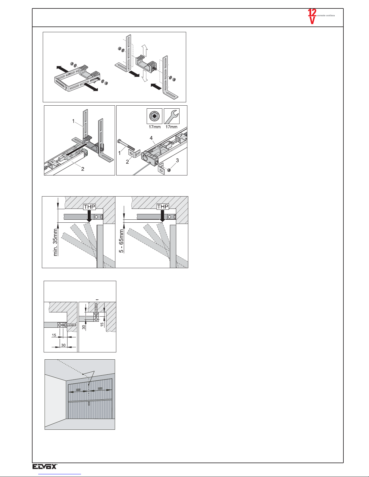
Fig. 8
Fit the bracket for the guide fixing to the ceiling as shown
in the figure.
Fig. 9
Insert the fixing bracket (1) in the guide (2).
Fig. 10
Fix the bracket, guide angle (2) with the screw (1) and
the nut (3) to terminal (4).
Fig. 11
Determine the highest opening point of the door (THP):
the ceiling must be above this point, and at a distance of
at least 35 mm.
The distance between the maximum door opening point
and the lower guide must be included between 5 mm
(min.) and 65 mm. (max), while the thrust arm must have
an angle of 30°.
Fig. 12
The guide can be fixed either on the architrave (A) either
to the ceiling (B).
Fig. 13
Measure the centre of the door (C) and mark the point on
the door, on the lintel and on the ceiling.
C
Fig. 13
Page 6

74
E
Fig. 15
Fig. 15) Open the door and mark the centre of the door on the ceiling (E).
Fig. 16
Insert the expansion plugs in the architrave (V) and raise the
guide (2). Fix the guide bracket (3) with two screws (4) by
using the washers (5). Lift the automatic system (2).
Fig. 17
Lift the guide (3) and align the bracket for the suspension to
the ceiling. The position must be in zone B, where B is 0 to 600
mm. long. Carry out two holes Ø 10x65 mm. and insert two
expansion plugs S10 (1) and fix tight the two screws 8x60 (2)
by using the two washers (2).
Fig. 16
Fig. 17
D
Fig. 14) Drill two holes (D) Æ 10 in the lintel or in the ceiling, 74 mm to the right and to the left of
the centre of the door (C).
Fig. 14
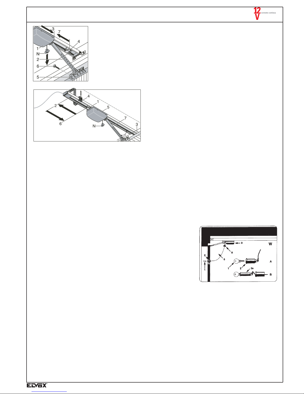
Fig. 18
Fig. 18
Fix (3) the door corner fitting (1) onto the rod, in a longitudinal
direction with respect to the position of the motor. Unlock the
motor by pulling the manual release (N).
ZN SERIES ACTUATOR
Page 7
75
Emergency release
1. Lower the red lever on the motor (N) to release it and open the horizontally pivoted door manually (see figure 19/ZN).
2. Install the manual release in the door using the appropriate bracket, which must be fixed in the handle of the door, secure it with
the cable clamp (type ZN24), and insert the cable in place of the red motor release lever.
3. With ELVOX kit type ZN23 it is possible to release the automated closure system from outside the door.
ZN SERIES ACTUATOR
Fig. 19) Regolare il fine corsa (4) spostandolo completamente verso il motore.
Move the motor (1) all the way forwards (3) with the rod. Align the door corner fitting (5)
with the centre of the doorway, drilling four holes ø5mm. Adjust the limit switch (4), moving it all the way up to the motor.
Fig. 19
max 30°
Fig. 20
Fig. 20) Move the limit switch (1) up to point (2), that is to say all the
way back. Open the door (3) manually from the side. Once
open it is possible to adjust the open limit switch.
N.B. If the sectional door does not close completely use the
adjustable bracket type ZN27.
Emergency release
- Pull the red lever in the motor (N) downwards once; so that the motor unlocks and the door can be opened manually (see figure
19).
- To install the manual release inside the door, fix it by means of the relative bracket inside the door handle, secure by means of a
cable clamp (type.ZN24), and position the cable in place of the red lever (W) of the motor release.
- If the area closed off by the garage door is not accessible from inside and the control needs to be released manually, an external
release device must be installed on the handle using the Elvox kit type ZN23.
Operation of external release device type.ZN23
The garage door can also be opened manually from the outside by means of the
motor release. For this purpose, insert key 1 (A) in cylinder 2 (Fig. a), turn it clockwise and remove with lock cylinder (B). At the same time cable 6 will release the motor.
External release device assembly
According to the type of garage door, choose one of the assembly options shown in
fig. b.
Fig. a
Drill a hole (diam. 20 mm) to insert the cylinder of lock 2 (fig.c) at approx. 60 cm from
the upper edge of the garage door.
If necessary, enlarge the hole from inside for threaded bushing 3 (diam. 23 mm; see
fig.c), and proceed with assembly.
In the case of sheet steel doors, drill four 4 mm holes for the washer (on a circumference of 26 mm.), (see fig. b letter F).
Now tie cable 6 (fig.c ) onto ring 7 (fig.c) of the lock cylinder. Tie the other end of the
cable to motor release cable 8 (fig.a.).
Avoid tensioning the cord.
Page 8

Fig. 21/ZN
Fig. 22/ZN
Installing the variable sectional door mounting type ZN27
Loosen the two screws and remove the U shaped section of the door mounting. Fasten to the sectional door mounting as illustrated.
Fig. 21/ZN: Set the sectional door mounting to the right length A, fix in place with 2 metal screws B and fasten to the upper section
of the door (X). Slide the boomerang C into the connecting rod D (U Section) and connect with 2 M10x25 bolts and nuts.
Fig. 22/ZN: If necessary shorten the connecting rod by sawing off accordingly and connect directly to the sectional door mounting.
76
ZN SERIES ACTUATOR
Fig. c
Fig. b
Page 9

77
ZN SERIES ACTUATOR
INSTRUCTIONS FOR THE CURVED ARM
For counterbalance up and over doors, remove approximately 3-8 Kg, according to the weight of the door. For spring up and over
doors, reduce the tension in the spring by 3-5 cm, according to the weight of the door.
Assembly:
1. Remove the door lock lever (1). Determine the point of maximum aperture of the swing device. Position the track 10-12 mm
above the door.
2. Position the curve (2) vertically and at the centre of the door, and bring it up to the top edge of the swing device (3). On the angle
irons (4) supporting the curve, position the holes so as to allow stable fixing to the door frame (5).
3. Screw the curve to the swing device frame. Install an emergency release (6) and move it so that the end of the curved arm (12)
is located at the hole in the motor block. Always leave a distance of almost 50 mm (see drawing).
If required, after removing the screws (7), modify the length in 25 mm steps (8), after first unlocking the spacer track (9).
Do not connect the curved arm to the motor yet!
4. Move the motor back (end part of the track).
5. Open the up and over device manually. Push the curved arm backwards.
6. Remove the lock nut (10) connecting the track to the ceiling. Move the track by an amount (see arrow) sufficient that the hole in
the motor (11) coincides with the hole in the curved arm. Connect the curved arm to the motor. Adjust the power and movement
as described in the assembly instructions.
Page 10

78
Fig. 23/ZN Install the box containing the control unit, preferably
close to the garage exit door, so as to use the existing
power socket. This socket must be installed at a minimum height of 1.6 metres above floor level.
The cable connecting the control unit and the C-track
has a maximum length of 6900 mm, and it must not be
extended!
Fig. 24/ZN To connect the cable in the control unit, unfasten screw
(1) and remove the cover over the box courtesy light (2).
The power supply to the control unit must not be turned
on yet.
Fig. 25/ZN Extract the electronic card (1) by pulling it upwards, and
disconnect it from the terminal board (2). Connect the
two wires from the motor power supply cable to the terminal board; the wire with number 3 printed on it must
be connected to terminal 3, and the one with number 4
printed on it must be connected to terminal 4.
Fig. 26/ZN Fix the power supply cable firmly to the rear side of the
box.
Fig. 27/ZN Mark the fixing points horizontal to the wall, at a distan-
ce of 110 mm. Drill two holes (ø6x40 mm depth). Fix
the box to the wall using two screws 4x50 (3) and two
plugs S6 (2).
ELECTRICAL INSTALLATION
ZN SERIES ACTUATOR
Programming the remote controls
Under no circumstances modify the length of the aerial cable!
Remove the elastic from around the red aerial cable, pushing it
upward (7) through the rear wall of the box, extracting it and fixing it
(Fig. 26/ZN).
Radio control code storage
Press and keep pressed the push-button present on the circuit
board for at least 3 seconds until the led turns on.
Now release the push-button and send the code from a radio control. If the operation was successful, the led turns off.
Cancellation of all codes stored
Press and keep pressed the push-button present on the circuit
board for at least 3 seconds until the led turns on. Release the
push-buttons and press it again. The les starts flashing. Press again
and keep pressed the push-button for at least 3 seconds until the led
flashes with a higher frequency and finally the led turns off.
N.B. The circuit board, with the 433 MHz receiver, can store up to
30 different radio control codes.
Adjusting applied force
The force required to open the door is adjusted automatically by the electronic card while it carries out self-regulation the first two
times the door is opened. During this operation, the courtesy light (2) will flash.
After turning the power supply to the control unit on, press the red button (6) fig. 26/ZN.
Open and close the door twice, during this operation the maximum values for the force to be applied to the door are read automatically by the microprocessor, and at the end of the operation the light (2) will stop flashing. After adjustment, use the remote control
or the red button (6) to operate the automatic door.
Deleting force values
1. Turn the control unit power supply off
2. Remove the screw and take the cover off the courtesy light in the box.
3. Press and hold the function button (3) T1 for three seconds, until the light (2) starts to flash, then release button T1 and the force
values will be deleted automatically.
Storing new force values
1. When the lamp (2) flashes the new force values must be stored. Press the button (6) in the box once, the door will open without
stopping until it reaches the limit switch. Once it has stopped, press the button (6) again and the door will close until it is completely shut.
2. Press the button (6) again: the door will open until it is completely open.
3. The force values both for opening and closing have now been read, and the light (2) will stop flashing.
4) Once the force has been regulated, fasten down the courtesy light cover in the box.
STARTING UP
Fig. 24/ZN
Fig. 23/ZN
Fig. 25/ZN
Fig. 28/ZN
Fig. 26/ZN
Fig. 27/ZN
Page 11
79
ZN SERIES ACTUATOR
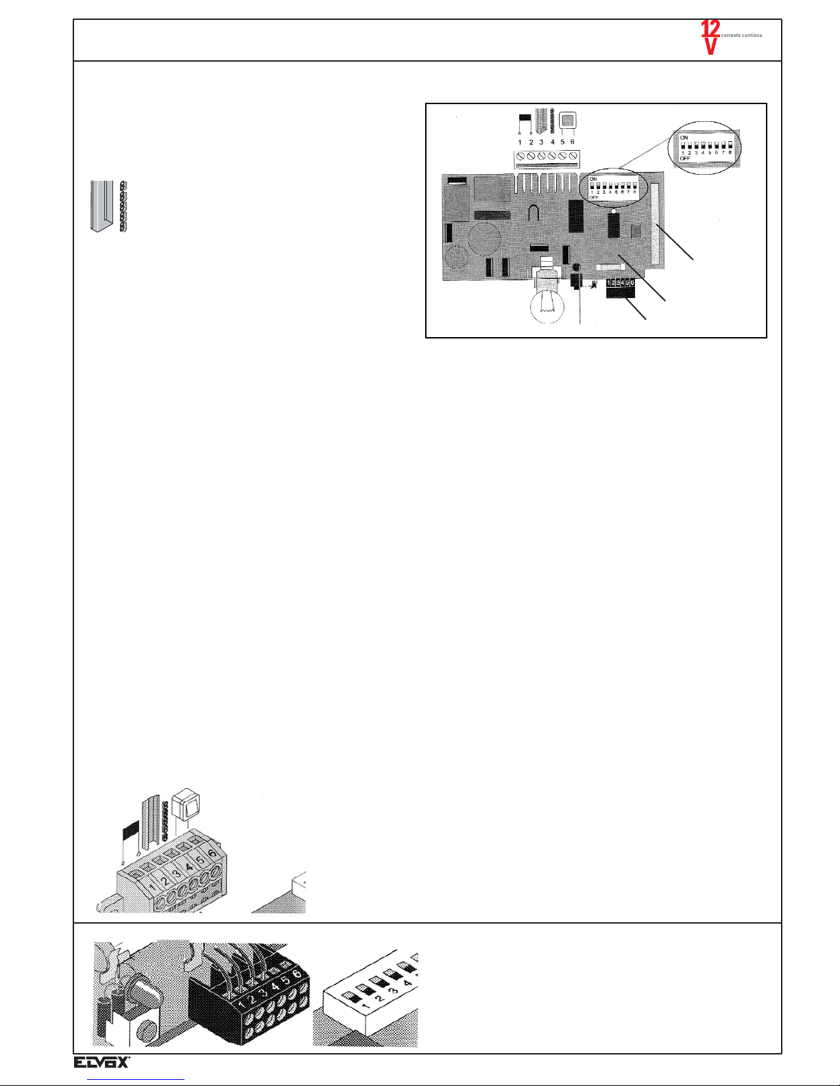
CONTROL UNIT
Description of control unit terminals
Fine wire fuses
6 DIL switches
Radio receiver unit
PROGRAMMING THE SWITCHES
Switch Posit. Function / Reaction
Reaction to security connected in input 1+2 of the accessory terminal block during the opening phase (example: photocell interruption)
1 OFF no reaction during opening
ON stop during opening
1+2 input operation for the accessory terminal block.
2 OFF NC security input (example: photocell)
ON NO input for 2nd actuator (example: partial opening)
Reaction to security connected to input 1+2 of the accessory terminal block during the closing phase (example: photocell interruption).
3 OFF partial inversion during the closing phase
ON
complete inversion during the closing phase (re-opening).
5+6 output operation of the accessory terminal block, for flashing light.
4 OFF Flashing impulse for flashing light
ON Indicator LED for the door state:
- Fixed lighted with open door
- switched off with door close
5 OFF pre-flashing deactivated
ON 3'' pre-flashing
Backjump (only during the closing phase)
To reduce the stress on the door and automation mechanics during the total closing phase, the automation moves shortly in the opening direction.
6 OFF deactivated
ON activated
Automatic closing
7 OFF deactivated
ON automatic closing after 1 minute (if 8 OFF).
8
(if 7 ON)OFF automatic closing after 1 minute
ON
automatic closing after 5'' from the photocell interruption.
When the horizontally pivoted door is open, the automatic closure function disables the radio controlled or push-button operated closure function.
Terminal
Terminal block connection for the circuit board
Terminal 1-2: transformer
Terminal 3: guide with C shaped section
Terminal 4: chain
Terminals 5-6:
wall push-button connection, free on automation.
Photocell connection
Terminal 1÷ 2 security connection, only if Switch 2 in OFF position
Terminal 3 ÷ 4 24V D.C. connection max 0,1A
terminal 3: 24V D.C.
terminal 4: earth
VAC
VAC
COM
AP/CH
Terminal:
1-2) Safety connection (LS or DW)
1: signal 2: earth
3-4) Output +24V, max. 1A, for example powering a photocell
3: +24V 4: earth
5-6) Connecting to flashing light 24V, max 1A
Fuse:
1 fuses 1AT/250V; 5x20 mm
24V output
]
Transformer power input
]
Open contact for optional external command.
]
C-track power supply
Page 12

80
ZN SERIES ACTUATOR
Flashing light connection:
Terminal 5 ÷ 6 24V D.C. connection (max 34V) not adjusted, max
1A
Cleaning the chain and the guide
If the chain (7) or the guide (8) are very dirty, clean them with a
clean cloth.
Every year lubricate slightly the chain with conductive oil.
Do not use grease! N.B. Use only conductive oil.
1- Fuse for flashing light connec-
tion, terminals 5 ÷ 6, 1A with
delayed action
Replacing the switchboard lamp
- Remove the electrical plug from the socket
- Unfasten the screws (1)
- Remove the transparent cover (2)
- Turn the lamp (3) leftwards and remove it.
- Insert the new lamp (24V, 21W, BA 15s type) and turn it rightwards until the end.
Replacing the switchboard fuses
- Remove the electrical plug from the socket
- Unfasten the screw (1)
- Remove the transparent cover (2)
- Pull off the control circuit board (3)
- Replace the faulty fuse. All fuses are 1A delayed
MAINTENANCE
Before carrying out any cleaning or maintenance operations on the motor, switch off the power by means of the appropriate magnetic/thermal switch upstream of the control unit and disconnect the back-up battery.
If the power supply is needed to carry out operational checks, disable all control devices (radio controls, keypads, etc.) except for
the device used by the maintenance technician. In general, the ZN10 electromechanical actuator requires little maintenance, but correct operation also depends on the condition of the door.
Both ordinary and extraordinary maintenance must be carried out by a specialised technician.
Routine maintenance:
Each of the following operations must be carried out on an “as necessary” or at least once every 6 months basis.
- If the chain is very dirty, clean it with a cloth.
- Lubricate the track with "conductive" oil
- Check that all the screws are tight, and if necessary tighten them.
- Check spring compensation and the up and over door mechanism.
Automatic system:
Check that all the safety devices (photocells, pneumatic stops, etc.) are operating properly, at the times and in the manner described by the manufacturer (see safety instructions).
Extraordinary maintenance:
Extraordinary maintenance operations are not anticipated, however if major work involving the mechanical parts is necessary, it is
advised to remove the actuator for repair (by specialised personnel).
Page 13

81
ZN SERIES ACTUATOR
Fig. 29/ZN
Fig. 30/ZN
SAFETY KIT FOR PEDESTRIAN DOOR
Type ZN26
To prevent entrapment between the horizontally pivoted door and the pedestrian door, it is necessary to install a microswitch so that
the automated closure system does not start operating when the pedestrian door is open.
TECHNICAL SPECIFICATIONS
- Microswitch contacts: NO-NC 230V A.C.
- Protection degree: IP66
INSTALLATION
1. Remove the motor cover.
2. Drill a hole of 98 ÷ 100 mm, and insert the cable supplied (see Fig. 29/ZN)
3. Remove connector two Faston coupling No. 5 (see Fig. 30/ZN), connect the device (A) between connector 5a and coupling No. 5.
To insulate the connection in the Faston coupling and in the connector, use the sheath supplied with the cable.
4. Refit the motor cover.
5. Remove the screw and the cover of device (A), connect the two conductors in the NO contact (NC with the door closed).
Page 14

82
ZN SERIES ACTUATOR
MR2
- + Vac Vac
MR1 MR3
124356
+
-
-
+
24V c.a.
ZN range automatic gate system
circuit board
Battery 2X12V
Transformer
Mains
230V ~
Battery charge Type ZNB1
INSTALLATION
- Disconnect the supply voltage
- Carry out connections to the electronic control circuit board as indicated in the fig. 31/ZN
Check the state of the battery charge with a multimeter (Tester) every 6 months. To obtain the maximum battery performances carry
out three charge/discharge cycles.
In case of replacement use original battery and recycle the others according to the norms in force (by specialized personnel).
In any case it is advised to replace the battery every 24 months.
Fig. 31/ZN
KIT OF BACK-UP BATTERY FOR AUTOMATIC GATE SYSTEMS ZN SERIES
Type ZNB1
GENERAL FEATURES
Kit of back-up battery, type ZNB1 with 4-Module DIN housing, for automatic gate systems for ZN range sectional doors and horizontally pivoted spring or counterweighted doors. In case of mains failure the back-up battery ensures a sufficient automation autonomy. If the battery is flat the motor can be manually released by pulling down the red lever.
115
134
61
67
Dimensions (mm)
TECHNICAL SPECIFICATIONS
Supply voltage: 26,6 V D.C.
Power : 120mA
Type of battery: 2x12V 3,2Ah
Battery recharge time: to Temp. 20° C: 24 Hrs (in stand-by)
16 Hrs
(for cyclical operation)
Operating temperature: 0° ÷ 40° C
Page 15

83
ZN SERIES ACTUATOR
PERIODICAL CHECK UP
Check the correct safety device operation periodically or in any case once a year (see ZH 1/494 April, 1989).
Monthly check up the correct operation of the safety devices, which are sensitive to pressure (for example switch trim). See EN60335-2-95.
Check up Reaction
Yes/No
Possible cause Solution
Disconnecting the
motive-power
Stop a door leaf with
a 50 mm high object
during the door
closing phase.
Emergency release
Follow instructions
described in paragraph "Emergency
release"
Safety switch trim,
if installed
Open/close the door
by activating the
switch trim simultaneously.
Photocell, if installed
Open/close the door
by interrupting
the photocell simultaneously.
- Leave all programmings unchanged
- Reduce the motive-power tolerance. Turn trimmer leftwards until the check up has positive
result. Open the door and close it completely
twice keeping it under control. See paragraph:
"Maximum motive-power adjustment ".
- Adjust the door, contact qualified personnel!
- Repair the emergency release.
- Check the door operation, see instructions:
"Door maintenance ".
- Check the cable, re-fasten the terminals.
- Reposition the switch
- Deactivate the installation and exclude the
reactivation. Contact the service personnel.
- Check the cable, re-fasten the terminals.
- Reposition the switch
- Clean the photocell
- Reposition the photocell
- Deactivate the installation and exclude the
reactivation.
- Contact the service personnel.
When the automation faces the
the object, it
inverts the motion
The door should
be easily opened
and closed
manually (the
door is balanced).
Door reaction
according to
programming of
switch 1, 2 or 3.
Door reaction
according to
programming of
switch 1, 2 or 3.
- The motive-power disconnection
works without limits.
- Trimmer on right limit stop.
Motive-power tolerance programming too high.
- The door is not correctly adjusted.
- The emergency release works
properly.
- The emergency release is faulty.
- The door got stuck.
- The security switch trim operates
correctly.
- Cable broken, loosened terminal.
- Switch displaced
- Faulty switch trim
- The photocell works correctly.
- Broken cable, loosened terminal
- Switch displaced
- Dirty photocell
- Photocell displaced (bent support)
- Faulty photocell
Yes
No
Yes
No
Yes
No
Yes
No
TROUBLESHOOTING- DIAGNOSTIC TABLE OF COMMON PROBLEMS
Faults in the garage door operator can be eliminated by following the instructions given in the table below. If you are unable to solve
the problem, please contact your dealer.
Problem Cause(s) Solution(s)
The door cannot be moved either
manually or electrically.
The automatic device does not work and
there is no light.
The automatic device does not work when
the remote control is used.
The door stops while closing, moves back
approximately 10 cm and then stops
again.
The door stops while opening.
The door can only be used if the button is
pressed, and the internal light flashes.
No light can be seen during opening and
closing of the door.
The speed changes during the opening
and the closing phase.
- Enable the emergency release (N) and
open the door manually.
See paragraph "Emergency release".
- Check using another electrical device, for
example a tester.
- Replace the fuse.
- Replace the battery
- Code the remote control. See paragraph
"Coding the remote control".
- Remove the obstacle and open the door
completely
- Adjust the limit switch again.
- Remove the obstacle and close the door
completely
- Adjust the limit switch again.
- Remove the obstacle, then move the
door to the final position, and the operator will once again work normally.
- Replace the bulb.
- Normal slowing down
- Clean the guide and lubricate it again
- Clean the guide and lubricate it again
- Tighten the chain
- There is a power cut
- The fuse in the garage power circuit has
blown
- The remote control battery is low.
- The remote control has not been correctly coded.
- Forced stoppage has been triggered due
to the presence of an obstacle.
- Limit switch badly adjusted.
- Forced stoppage has been triggered due
to the presence of an obstacle.
- Limit switch badly adjusted.
- Forced stoppage has been triggered due
to the presence of an obstacle.
- Blown lamp
- The automation starts slowly and then
accelerates.
- The chain guide is dirty
- The chain guide has been lubricated
with the wrong type of oil
- Chain not correctly stretched.
 Loading...