

Page 1

Installer manual
SL24.W
Control panel for sliding gates 24 Vdc
Page 2

SL24.W
Contents: Page
Product features ................................................................................................................................................. 1
System type ........................................................................................................................................................ 2
Description of the terminal blocks....................................................................................................................... 2
Power supply connection.................................................................................................................................... 3
Connecting accessories ..................................................................................................................................... 3
Programming the control panel .......................................................................................................................... 6
Diagnostics ......................................................................................................................................................... 18
Updating rmware .............................................................................................................................................. 19
Control panel behaviour when loading settings .................................................................................................. 19
Control panel connection from Smartphone/Tablet ............................................................................................ 20
2
EN
Page 3
SL24.W
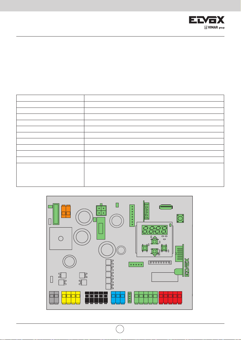
1 - Product features:
Control panel for gear motors for 24Vdc sliding gates. The control panel:
- is equipped with an integrated 433 MHz rolling code or xed code receiver, storing up to 4032 codes
- is equipped with W-Fi connection and programming via Smartphone and Tablet using the EMC.W module and the
Wi-Gate app is equipped with a back-lit display for programming and diagnostics
- is used to customise all gate movement control parameters (speed and slowdown spaces, motor force, obstacle
sensitivity, reaction to obstacles, acceleration and deceleration ramps...)
- is equipped with fully congurable inputs and outputs
- is used to lock the control panel and receiver settings with a 4 digit password protection
Technical data:
Power supply 24 Vac
Motor supply voltage 24 V DC
Maximum motor power 150 W
Flashing light output 24 V DC 35 W max
Accessories power supply 24 V DC 500 mA
Receiver memory 4032 Elvox rolling codes
Receiver frequency 433 MHz
Remote controls code Rolling code or xed
Fuse F1 ATO line protection 15 A
Fuse F2 Accessories protection 5x20 mm F 3.15A
Operating temperature -10 to +50°C
MEM for memory module MEM.W connection (included)
Ports
RADIO for radio module 433RAD.W connection (included)
USB for rmware updating
CNX1 for Wi-Fi EMC.W module connection
CNX2 for opposing leaf module connection
VIMAR group
T1 T2
SEC
DL4
T2T1
VR3
F1
PT1
FSC1
MOT PS
21 22 0 1 1 2
21 22 0112
BAT
DL3
AUX LSW ENC ACT SAF
10 11 0
10 11 0
PWR
F2
99 31 32 C3C499 S1 S2 S3
99 31 32 C3 99 S1 S2 S3
MEM
CNX1
PROGRAM. MENU'
ESC OK
CNX2
C1C299
C1C299
EN
CNP1
SL24.W
C4
USB
PP
DL1
RADIO
S4A1 A2
S4A1 A2
1
Page 4
SL24.W
T2T1
BAT
F1
SEC
VR3
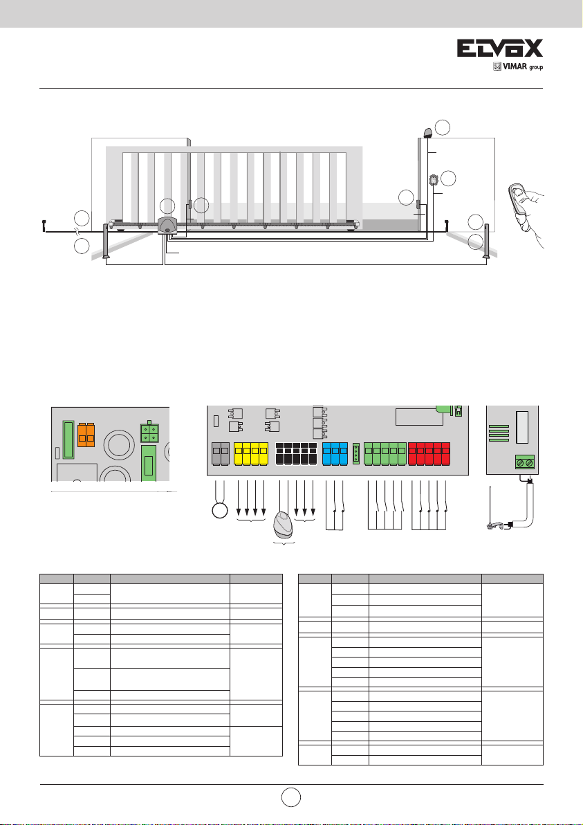
2 - System type:
For the sizing of the cable routing, the required cross-sections of the cables are shown below.
F
A
G
2x0.5 mm
Legend
A. Gear motor
B. Rack
C. External photocells
D. Flashing light
E. Selector
F. Internal photocells
G. Photocell posts
3 - Description of the terminal block
SEC
T2T1
VR3
F1
BAT
2
3x1.5 mm2 (230 Vac)
C
2
4x0.5 mm
FSC1
MOT PS
21 22 0 1 1 2
21 22 0112
OPEN M1
CLOSE M1
M1
24 V-
24 V+
500 mA max
2
4x0.5 mm
AUX LSW ENC ACT SAF
99 31 32 C3C499 S1 S2 S3
99 31 32 C3 99 S1 S2 S3
24 V-
COM
A1 24 V+
A2 24 V+
BLINK 24 V+
500 mA max
24 V+
24 V+ TEST
35 W max
10 11 0
10 11 0 A1 A2
BLINK 24 V-
2x0.5 mm
C1C299
C1C299
COM
C
2
SL24.W
C4
COM
D
4x0.5 mm
E
3x0.5 mm
S4A1 A2
S4
2
2
F
G
433RAD.W
ANT
- ANT
Block Terminal Description Rated data
T1
SEC
BAT - Battery pack rapid coupling
MOT
PS
Secondary transformer 24 Vac
T2
21 Opening motor (white)
22 Closing motor (brown)
Accessory power supply
0
negative
Accessory power supply
positive
2 Accessories positive checked
10 Flashing light negative 24 V DC
11 Flashing light positive
AUX
0 Accessories negative
A1 Congurable output 1 positive
A2 Congurable output 2 positive
2
24 V DC
150 W
24 V DC
500 mA1
35 W
24 V DC
500 mA
Block Terminal Description Rated data
99 Inputs common (blue)
31 Limit switch 1 (brown)
LSW
32 Limit switch 2 (black)
ENC - Motor encoder
99 Control common
C1 Congurable control 1
ACT
C2 Congurable control 2
C3 Congurable control 3
C4 Congurable control 4
99 Safety device common
S1 Congurable safety device 1
PS
S2 Congurable safety device 2
S3 Congurable safety device 3
S4 Congurable safety device 4
ANT Aerial signal
ANT
- Aerial earth
EN
N.C.
N.O.
N.C.
Page 5
SL24.W
(230 Vac) 5x20mm T 2A
ACT
COM
C1=1 (P.P.)
C2=2 (PED)
C3
C4
C1C299
ACT
COM COM
N.O. N.O.
N.C. N.C.
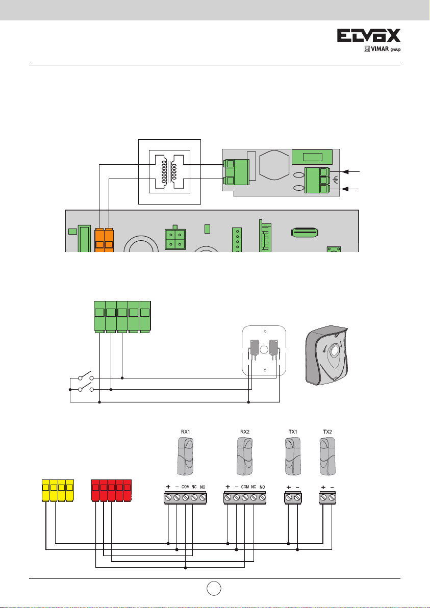
4 - Power supply connection
The control panel is powered at the SEC terminal with 24Vac and must be connected to the secondary terminal of a
transformer for powering from the mains electricity. The transformer is supplied with the gear motor or control cabinet
the control is tted in and the secondary is pre-wired to the control panel. The primary terminal on the transformer is
already wired to the mains lter, also supplied with the gear motor or the control cabinet, for connecting the mains lter
to the mains electricity refer to the image below:
(120 Vac) 5x20mm T 4A
LN
FA
L
230 Vac
120 Vac
N
T2
T1
SEC
DL4
T2T1
3
5 - Connecting accessories
5.1 - Key switch and control device
C3
C1
99
C2
COM
Pedestrian
Step by step
5.2 - Key switch and control device
PS
0 1 1 2
24 V-
24 V+
99
COM
C1=1 (P.P.)
SAF
S1 S2 S3
S2=2 (PH)
S1=1 (PHC)
C2=2 (PED)
S4
C4
BAT
PWR
MEM
CNX1
COM COM
N.C. N.C.
N.O. N.O.
USB
VIMAR group
EN
3
Page 6
SL24.W
24 V-
99 S1 S2 S3
S4
SAF
COM
24 V-
24 V+
S1=1 (PHC)
S2=2 (PH)
0 1 1 2
PS
COM
C1=1 (P.P.)
C2=2 (PED)
C3
C4
C1C299
ACT
COM COM
N.O. N.O.
N.C. N.C.
COM
99 S1 S2 S3
S4
SAF
COM
S1=4 (BAR)
S2=5 (8k2)
SAF
COM
S1=6 (STP
N.C.8K2 (8.2 KΩ)
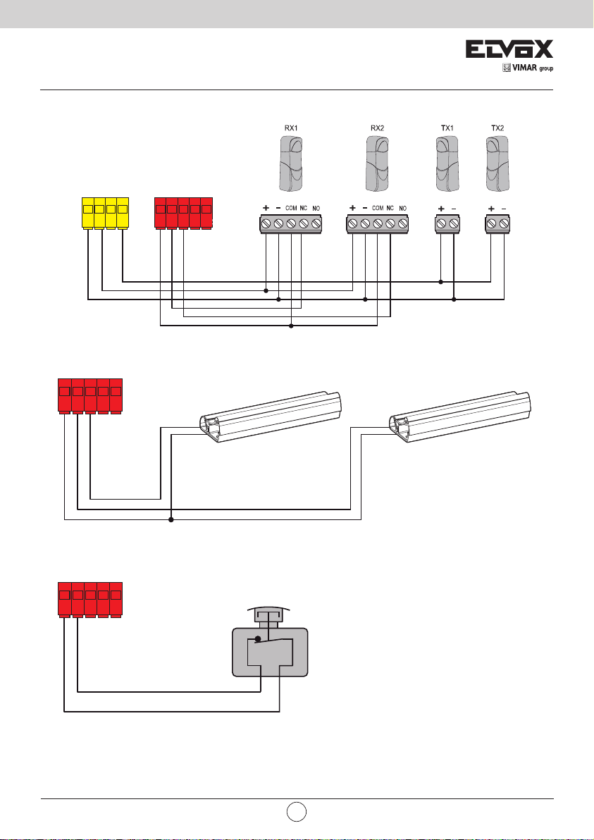
5.3 - Photocells and photocells in closing with photo-test on
5.4 - Sensitive edge
S1 S2 S3
99
S1=4 (BAR)
5.5 - Stop push button
PS
0 1 1 2
24 V+
SAF
S4
S2=5 (8k2)
24 V+ TEST
SAF
99 S1 S2 S3
COM
S2=8 (PHT)
S1=7 (PTCH)
S4
N.C.8K2 (8.2 KΩ)
4
99 S1 S2 S3
)
S4
EN
Page 7
SL24.W
AUX LSW ENC ACT SAF
AUX LSW ENC ACT SAF
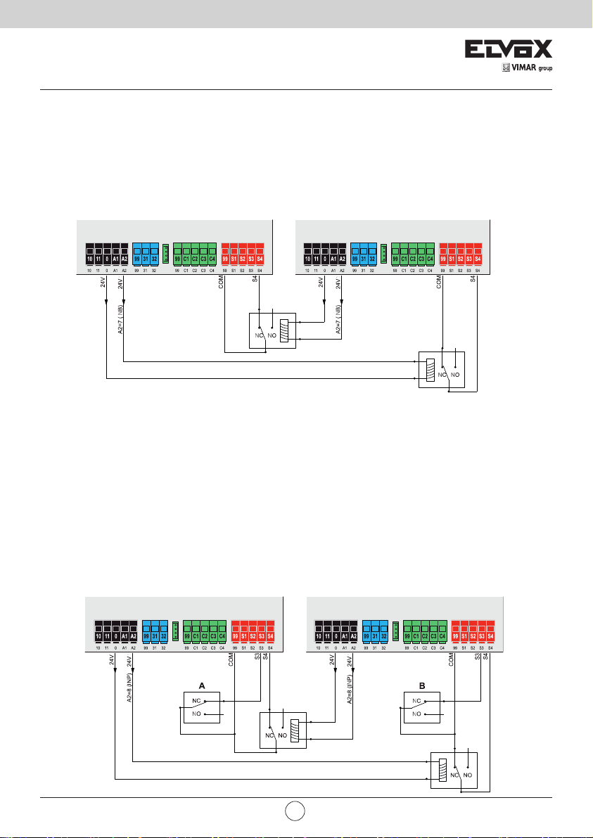
5.6 - Connecting two control panels in interlocking mode, output A2 = 7 (INB)
The interlocking connection involves 2 gates operating according to the following method:
- gate 1 opens only if gate 2 is closed
- gate 2 opens only if gate 1 is closed
When this mode is on, the safety input S4 is automatically congured without the installer selecting it as
an interlock input (checking that the other gate is closed). The two control panels operating in interlocking
mode must be connected by interposing 2 relays as shown in the gure:
AUX LSW ENC ACT SAF
AUX LSW ENC ACT SAF
5.7 - Connecting two control panels in interlocking mode with presence, output A2 = 8 (INP)
The interlocking connection with consent to opening from presence signal involves 2 gates operating
according to the following method:
- gate 1 opens only if gate 2 is closed
- gate 2 opens only if gate 1 is closed
- gate 1 opens only if there is a presence signal
- gate 2 opens only if there is a presence signal
When this mode is on, the safety input S4 is automatically congured without the installer selecting it as
an interlock input (checks the state of closure of the other gate) and the safety input S3 is congured
automatically as the presence input. The two control panels operating in interlocking mode must be connected by interposing 2 relays and using accessories which send the presence signals to the control
panels (e.g. magnetic coils A and B) as shown in the gure:
AUX LSW ENC ACT SAF
AUX LSW ENC ACT SAF
VIMAR group
EN
5
Page 8
SL24.W
6 - Control panel programming:
6.1 - Preliminary operations
To function correctly, the control panel requires some minimum and essential settings. There are two:
- Setting the motor type.
In its default conguration, the control panel is not associated to any type of motor. The type of motor associated to the
control panel must be set.
- Gate travel calibration
The control panel must know some physical parameters of the gate in order to function correctly. The operation allowing
the control panel to know these physical gate parameters is called travel calibration. If this is not done, the control panel
may not perform slowdowns or detect obstacles correctly.
6.2 - Using the display
The control panel is programmed using the display and the navigation buttons on board or via Smartphone/Tablet (see
paragraph "Wi-Fi connection to Smartphone/Tablet"). The control panel settings are shown on the display and can be
edited using the menu navigation buttons as shown in the following table:
Buttons Function Pressure length
OK
▲
▼
ESC
▲+▼ Resetting the card 3 s
▲+ OK Opening control 1 s
▼+ OK Closing control 1 s
ESC + OK
ESC + OK When the board is switched on the Firmware updating mode starts 3 s
PP Step-step control Instantaneous
Switching on the display
Sub-menu entry
Conrm value change and return to menu
Scroll up
Increase parameter value
Scroll down
Reduce parameter value
Exit the menu
Cancel value change and return to menu
Switching o the display
Display test (switches on each segment of the display and points individually in
sequence)
Instantaneous
Instantaneous
Instantaneous
Instantaneous
3 s
6.3 - Menu
The control panel programming is organised into menus and sub-menus used to access and edit the parameters and
logics of the control panel. The control panel is equipped with the following rst-level menus:
Menu Description
MOT Motor parameters setup
LRNT Travel calibration procedure run menu
TRV Travel parameter settings menu
OUT Auxiliary output conguration menu
IN Input conguration menu
LGC Operating logic settings menu
RAD Remote control management menu
STAT Diagnostic and reporting menu
EXP Expansion board management menu
LOAD Default value restore menu
PASS Protection level settings menu
All sub-menus are described in the following table
6
EN
Page 9

SL24.W
Motor parameters
Type of gear motor used
O1
OFF Not set
1 Acto 600D (ESM2)
Type of position control
Automatically set with the choice of gear motor. You are advised not to change the setting
given by the type of gear motor.
O2
2 Virtual encoder: the control panel calculates the gate position using the electric motor operat-
3 Encoder for Acto 600D (ESM2)
MOT
Type of limit switch on opening
Automatically set with the choice of gear motor. You are advised not to change the setting
given by the type of gear motor.
OFF No limit switch on opening: the electric motor stops at the end of the working time
O3
1 Stop limit switch on opening: the limit switch stops the motor
2 Limit switch in proximity opening: the limit switch allows the manoeuvre to continue at the
Type of limit switch on closing
Automatically set with the choice of gear motor. You are advised not to change the setting
given by the type of gear motor.
OFF No limit switch on closing: the electric motor stops at the end of the working time
O4
1 Stop limit switch on closing: the limit switch stops the motor
2 Limit switch in proximity closing: the limit switch allows the manoeuvre to continue at the
Gate travel calibration
Rapid travel calibration.
The calibration is done fully automatically and sets:
- The slowdown in opening at 20% of the total travel
- The slowdown in closing at 20% of the total travel
- Pedestrian opening at 30% of the total travel
Pressing button
LRNE
- PP Wait for start of calibration procedure
PP CL 1 When button pressed: closing and search for closing limit switch
- OP 1 Opening travel measurement
- CL 1 Closing travel measurement
- OPC1 Opening current curve reading
- CLC1 Closing current curve reading
- END End of procedure
Advanced travel calibration.
The calibration allows the installer to choose:
LRNT
- Slowdown position in opening
- Slowdown position in closing
- Pedestrian opening position
Pressing button
- PP Wait for start of calibration procedure
PP CL 1 When button pressed: closing and search for closing limit switch
PP OP 1
LRNA
- OP 1
PP CL 1
- CL 1 Continuation of opening and slowdown speed up to closing limit switch
PP OPED
- CPED Leaf closing from pedestrian opening position
- OPC1 Opening current reading
- CLC1 Closing current reading
- END End of procedure
ing parameters
approach speed set until it detects the mechanical stop
approach speed set until it detects the mechanical stop
Msg on
display
Msg on
display
Phase description
Phase description
Start opening. When button pressed: slowdown start position on opening setting
Continuation of opening and slowdown speed up to opening limit
switch
Start closing. When button pressed: slowdown start position on closing
setting
Start pedestrian opening. When button pressed: pedestrian opening
position setting
Default
1
Default
3
Default
1
Default
1
VIMAR group
EN
7
Page 10

SL24.W
Self-calibration
If the gate travel parameter is changed, there is no need for the installer to run new calibrations, however, when changing the travel parameters, the control panel needs to learn the current curve again, thus disabling the obstacle detection
only during the self-calibration manoeuvre.
Self-calibration is appropriately signalled:
- on the control panel display by the code AT
- by the light ashing at twice the normal frequency
The events generating self-calibration are:
- change in parameters: T24, T26, T28, T30, T32, T34, T40
- loading of settings from a MEM.W memory card
- reset/import of settings from the Wi-Gate app
Gate travel parameters
TRV
Motor force (%).
Sets the value of the force given to the motor to push the leaf
T1
1 Minimum force
100 Maximum force
Direction.
Sets the motor direction
1 Left gear motor (the gate seen from the side where the gear motor is installed opens
T4
2 Right gear motor (the gate seen from the side where the gear motor is installed opens
Choice of intervention method for obstacle detection
1 Overcurrent or leaf stopped: the obstacle is detected when the current threshold or the
T7
2 Leaf stopped: the obstacle is detected only when the leaf slows down excessively
3 Overcurrent: the obstacle is detected when the current threshold is exceeded
4 Overcurrent and leaf stopped: the obstacle is detected when the current threshold and
Motor obstacle detection time on opening
Time after which the current threshold or the encoder threshold trigger the obstacle detection
on opening (adjustable at intervals of 100 ms)
T8
10 100 ms (minimum time)
60 600 ms (maximum time)
Motor obstacle detection time on closing
Time after which the current threshold or the encoder threshold trigger the obstacle detection
on closing (adjustable at intervals of 100 ms)
T9
10 100 ms (minimum time)
60 600 ms (maximum time)
Polling time
Time during which the motor pushes with maximum force to move the leaf (adjustable at
intervals of 0.5 s)
T12
0.5 0.5 s (minimum time)
5.0 5.0 s (maximum time)
Pedestrian opening position (% of total opening travel)
T13
10 Minimum position
100 Maximum position
Disengagement space on obstacle
(inversion distance following the detection of an obstacle)
OFF Not disengaged, stops only
T14
1 Minimum inversion
10 Maximum inversion
towards the left)
towards the right)
encoder slowdown threshold is exceeded
the encoder slowdown threshold are exceeded at the same time
Default
50
Default
1
Default
1
Default
20
Default
20
Default
2.0
Default
30
Default
5
8
EN
Page 11

SL24.W
T15
T17
T24
T26
T28
TRV
T30
T32
T34
T36
T38
T40
Motor stop approach force reduction distance
Indicates the distance from the mechanical stop starting from which the motor force is
reduced by half (used to adjust the impact of the leaf on the mechanical stop).
This happens only when the control panel works with encoder and proximity limit switch or
without limit switch.
OFF Force reduction o
10 Minimum force reduction distance
100 Maximum force reduction distance
Easy release
Disengagement time after manoeuvre to reduce the motor pressure on the mechanical stop
(adjustable at intervals of 100 ms)
OFF No disengagement
10 100 ms (minimum disengaging)
50 500 ms (maximum disengaging)
Normal motor speed when opening
1 minimum speed
100 maximum speed
Normal motor speed when closing
1 minimum speed
100 maximum speed
Motor slowdown speed when opening
1 minimum speed
100 maximum speed
Motor slowdown speed when closing
1 minimum speed
100 maximum speed
Motor slowdown distance when opening
% of travel or total work time done at slowdown speed
0 No slowdown
100 Slowdown for the whole distance
Motor slowdown distance when closing
% of travel or total work time done at slowdown speed
0 No slowdown
100 Slowdown for the whole distance
Motor acceleration time when opening
Time during which the motor accelerates to reach the normal opening speed (adjustable at
intervals of 0.1 s)
0 Maximum acceleration (0 s to reach normal speed)
2.0 Minimum acceleration (2.0 s to reach normal speed)
Motor acceleration time when closing
Time during which the motor accelerates to reach the normal closing speed (adjustable at
intervals of 0.1 s)
0 Maximum acceleration (0 s to reach normal speed)
2.0 Minimum acceleration (2.0 s to reach normal speed)
Motor deceleration ramp
Deceleration ramp between normal motor speed and slowdown speed
0 Steep ramp (maximum deceleration)
100 Low ramp (minimum deceleration)
Default
OFF
Default
OFF
Default
90
Default
90
Default
30
Default
30
Default
20
Default
20
Default
0.5
Default
0.5
Default
30
VIMAR group
EN
9
Page 12

SL24.W
Auxiliary output conguration
Terminal A1 output type
OFF Output o
Gate open warning light (SCA)
1
Operation as per SCA parameter setting
Auxiliary Radio output (RAU)
2
Operation as per RAU parameter setting
Courtesy light (LCO)
3
A1
OUT
A2
RAU
RAUT
On during leaf movement and for the amount of time after the leaf stopping set in parameter
LCO
Zone light (LZO)
4
On during leaf movement
Gate left open (OAB)
5
On if the gate remains open for a time longer than that dened by the open gate alarm logic
(L16)
Maintenance (MAN)
6
Output o when the number of maintenance signalling manoeuvres (MNPS) is reached in the
diagnostics section
Terminal A2 output type
OFF Output o
Gate open warning light (SCA)
1
Operation as per SCA parameter setting
Auxiliary Radio output (RAU)
2
Operation as per RAU parameter setting
Courtesy light (LCO)
3
On during leaf movement and for the amount of time after the leaf stopping set in parameter
LCO
Zone light (LZO)
4
On during leaf movement
Gate left open (OAB)
5
On if the gate remains open for a time longer than that dened by the open gate alarm logic
(L16)
Maintenance (MAN)
6
Output o when the number of maintenance signalling manoeuvres (MNPS) is reached in the
diagnostics section
Synchronization output, compass type interlock (INB)
7
Automatically congures input S4 as synchronization input without any choice by the user.
The control panel consents to the gate opening only if the other gate is in the closed position
Synchronization output, compass type interlock (INP) with presence signal.
Automatically congures input S4 as synchronization input and S3 as presence input without
8
any choice by the user.
The control panel consents to the gate opening only if the other gate is in the closed position
and the presence input is occupied
Auxiliary Radio Output Conguration
1 Impulsive: the output is active for 1 s following the RAU command from the remote control
Timed: the output is active for the time set in the RAUT parameter following the RAU command
2
from the remote control
3 Bistable: the output works in Step-Step ON/OFF mode
RAU output timing
1 1 s (minimum time)
600 600 s (maximum time)
Default
1
Default
2
Default
1
Default
1
10
EN
Page 13

SL24.W
LCO
OUT
SCA
Input conguration
IN
C(X)
Courtesy light timer
1 1 s (minimum time)
300 300 s (maximum time)
SCA output operating mode
Gate closed: o
1
Gate open: on xed
Gate closed: o
Gate moving: intermittent
2
Gate open: on xed
Indeterminate position: intermittent pause of 1 s every 5
Gate closed: o
Gate opening slow intermittent
3
Gate open on xed
Gate closing intermittent
Indeterminate position: intermittent pause of 1s every 5
Gate stopped on xed
4
Gate moving o
Gate closed o
5
Gate moving on xed
C1/C2/C3/C4 command input
Step-step (PP)
The step-step control:
- with the gate stopped and closed, opens the gate
1
- in opening, stops or closes the gate according to the step-step logic setting (L10)
- with the gate stopped after opening, closes the gate
- in closing, stops or opens the gate according to the step-step logic setting (L10)
- with the gate stopped after closing, opens the gate
Pedestrian (PED)
Opens the gate to the pedestrian position
2
It acts like a step-step if the command is given with the gate beyond the pedestrian position
Open (OPEN)
The open command:
- with the gate stopped and closed, opens the gate
3
- in opening is ignored
- with the gate open, resets the pause time
- with the gate stopped, opens the gate
- in closing, opens the gate
Close (CLS)
The close command:
- with the gate stopped and closed, is ignored
4
- in opening, closes the gate
- with the gate stopped, closes the gate
- in closing is ignored
Timer (TIM)
The timer command:
5
- when closed, opens the gate and keeps it open as long as the contact remains
closed
- when the contact is released it closes the gate
Pedestrian Timer (TIMP)
6
Has the same function as the timer command but on the pedestrian position
Default
120
Default
1
Default C1
Default C2
Default C3
Default C4
VIMAR group
EN
11
Page 14

SL24.W
IN S(X)
S1/S2/S3/S4 safety input
OFF O Default S3/S4
Photocell closing (PHC)
The closing photocell:
- with the gate stopped, allows the gate to open
1
- in opening does not intervene
- with the gate open, does not allow it to close and when released will reset the
pause time
- in closing, reopens the gate immediately
Photocell (PH)
The photocell:
- with the gate stopped, does not allow the gate to open
2
- during opening stops the movement and when released proceeds with opening
- with the gate open, does not allow it to close and when released will reset the
pause time
- in closing stops the movement and when released reopens the gate
Opening photocell (PHO)
The opening photocell:
- with the gate stopped, allows the gate to open
3
- in opening, recloses it completely
- with the gate open, allows it to close and does not reset the pause time
- in closing does not intervene
Sensitive edge with NC clean contact (BAR)
- with the gate stopped, does not allow the gate to open
- in opening disengages
4
- with the gate open, does not allow it to close and when released will reset the
pause time
- in closing disengages
8.2 KΩ balanced sensitive edge (8K2)
5
Same behaviour as the NC sensitive edge
Stop (STP)
6
- stops the gate
Interrupts the automatic closing as per the logic stop setting from stop (L12)
Photocell closing checked (PHC)
7
As per closing photocell but with check
Photocell checked (PHT)
8
As per photocell but with check
Photocell opening checked (PHC)
9
As per opening photocell but with check
NC sensitive edge checked (BART)
10
As per KΩ NC sensitive edge but with check
8.2 KΩ balanced sensitive edge checked (8K2T)
11
As per 8.2 KΩ sensitive edge but with check
Default S1
Default S2
12
EN
Page 15

SL24.W
Control panel logic settings
Automatic closing
L1
OFF Automatic closing o
ON Automatic closing on
Pause time
L2
1 1 s (minimum time)
180 180 s (maximum time)
Pedestrian pause time
L3
1 1 s (minimum time)
180 180 s (maximum time)
State on power up
CL
L4
OP
LGC
Apartment block
OFF Apartment block function o
L5
1 Ignores closing and stop commands in opening
2 Ignores closing and stop commands in opening and in pause
3 Ignores closing and stop commands in opening, in pause and in closing
Rapid closing
OFF Rapid closing function o
1 Rapid closing in gate mode:
L6
2 Rapid closing in barrier mode:
Clearance time (adjustable at intervals of 1 s)
Time after which the gate closes again if the rapid closing (L6) is on
L7
1 Minimum clearance time
10 Maximum clearance time
Default
ON
Default
30
Default
20
Default
Gate in closed position:
The rst step-step command opens the gate.
Gate in open position:
The rst step-step command closes the gate. If automatic closing is on, after the pause time
the gate closes
The control panel starts to count the clearance time (L7) from when the closing photocell is
released, when the clearance time expires it closes again.
The control panel starts to count the clearance time (L7) from when the closing photocell is
released, when the clearance time expires it closes again. If the closing photocell is occupied
again, it does not command it to reopen but to stop. When released again it continues with
closing. The closing photocell returns to normal operating after complete closure
OP
Default
OFF
Default
OFF
Default
2
VIMAR group
EN
13
Page 16

SL24.W
LGC
Pre-ash
Flashing time of the ashing light before the gate starts to move
OFF Pre-ash disabled
L8
3 3 s pre-ash
4 4 s pre-ash
5 5 s pre-ash
Manned
OFF Manned function o
1 Step-step command disabled, remote controls not working. The control panel accepts only
L9
L10
L11
L12
L14
L15
L16
open and close commands
2 Emergency manned. In normal standard operating conditions, with the safety devices occu-
pied it works as manned.
Step by step
2 Step-step command operates in 2 steps: open, close, open...
3 Step-step command operates in 3 steps: open, stop, close, open...
4 Step-step command operates in 4 steps: open, stop, close, stop, open...
Stop from step-step
OFF Automatic closing disabled when a stop command from step-step is given
ON Automatic closing not disabled when a stop command from step-step is given
Stop from stop
OFF Automatic closing disabled when a stop command from stop is given
ON Automatic closing not disabled when a stop command from stop is given
Operation in battery
1 Standard operation
2 Normal operation with ashing light disabled
3 After a re-open command it stays open
4 When the main power supply is cut o it opens and remains open
Economy
OFF Standard operation
1 Economy operation on. With the gate closed, it switches o the accessory power supply on
outputs 1 and 2. The outputs are powered again following a new command.
Gate blocked open indicator
Number of minutes after which, with the gate partially or totally open, whatever the set
pause time, an alarm signal is sent (on the display and output congured as OAB)
OFF Indicator disabled
3 Minimum interval
60 Maximum interval
Default
OFF
Default
OFF
Default
4
Default
ON
Default
ON
Default
1
Default
OFF
Default
30
14
EN
Page 17

SL24.W
Remote control management
Saving a button as step-step
oooo Waiting for code
PP
1001 Remote control 1 saved as step-step
1055 Remote control 55 saved as step-step
Saving a button as open
oooo Waiting for code
OPEN
2001 Remote control 1 saved as open
2055 Remote control 55 saved as open
Saving a button as pedestrian
oooo Waiting for code
PED
3001 Remote control 1 saved as pedestrian
3055 Remote control 55 saved as pedestrian
Saving a button as Auxiliary Radio Output activation
oooo Waiting for code
RAU
4001 Remote control 1 saved as Auxiliary Radio Output
4055 Remote control 55 saved as Auxiliary Radio Output
Saving a button as close
oooo Waiting for code
CLS
5001 Remote control 1 saved as close
5055 Remote control 55 saved as close
Saving a button as stop
oooo Waiting for code
STP
6001 Remote control 1 saved as stop
6055 Remote control 55 saved as stop
Saving a button as Courtesy light on
oooo Waiting for code
LCO
7001 Remote control 1 saved as Courtesy light on
RAD
7055 Remote control 55 saved as Courtesy light on
Control of remote control memory position
oooo Waiting for code
5001 Remote control button 1 saved as close
CTRL
7099 Remote control button 99 saved as Courtesy light on
-030 Remote control button 30 not in memory
---- Remote control not in memory
Remote control programming
OFF Remote programming of remote controls o
1 Remote programming of remote controls on:
RE
Total receiver memory deletion
ERSA
oooo Signals the deletion of the receiver memory on the display
Deletion of single remote control from its position in the memory
ERS1
X Use buttons ▲▼ to select the number of the remote control to delete
Deletion of single remote control from the remote control code
ERSR
oooo Waiting for code
Default
1
used to programme remote controls from a remote control already in the memory, using
the following procedure:
-press buttons 1 and 2 on the remote control already in the memory at the same time
-press the button on the remote control already in the memory to copy on the new remote
control
-press the button on the new remote control on which to copy the button just pressed on
the remote control already in the memory
Note: the button on the new remote control just saved inherits the function assigned to the
button on the remote control already in the memory
Press OK for 5 s
Press OK to conrm
Deleting remote control
VIMAR group
EN
15
Page 18

SL24.W
Diagnostics and reporting
ALM
ALMA
MNPC
MNPS
MNPA
MNPE
MNTC
STAT
LIFE
PONC
PONE
RSTC
RSTE
TL
INF
Alarm log reading
0 Most recent alarm
10 Oldest alarm
Error signals
1 Only on display
2 On display and maintenance output
Reading of number of manoeuvres since last maintenance
002 First 3 digits of the number of manoeuvres since last maintenance
3256 Last 4 digits of the number of manoeuvres since last maintenance
In the case described above, the gate has carried out 23,256 manoeuvres since the last maintenance
Number of manoeuvres since last maintenance
Number of manoeuvres generating a maintenance signal (in thousands of manoeuvres)
OFF Maintenance signalling o
1 1,000 manoeuvres (minimum interval)
300 300,000 manoeuvres (maximum interval)
Maintenance signalling
1 Signalling only on display
2 Signalling on display and maintenance output (MAN)
3 Signalling on display and ashing light (rapid ashing at end of manoeuvre)
4 Signalling on display, ashing light (rapid ashing at end of manoeuvre) and mainte-
Reset manoeuvres since last maintenance counter
oooo Waiting press OK for 5 s to reset the counter to 0
Total manoeuvres counter
012 First 3 digits of the number of manoeuvres since last maintenance
5874 Last 4 digits of the number of manoeuvres since last maintenance
In the case described above, the gate has carried out 125,874 manoeuvres in total
Life counter (days of activity of the control panel)
584 Reading of the number of days of activity of the control panel
In the case described above, the control panel was active for 584 days
Number of control panel power-ups counter
2547 Reading of the number of control panel power-ups
In the example shown above, the control panel was powered up 2547 times (it could indicate a
poor quality mains electricity, with frequent power cuts)
Reset number of control panel power-ups counter
oooo Waiting press OK for 5 s to reset the counter to 0
Number of self-reset counter
1123 Reading of the number of control panel self-resets
A self-reset is a reset of the microswitch by the control panel for safety reasons. Typically the control panel goes to self-reset when the minimum microswitch voltage threshold has been reached.
An excessive number of self-resets could indicate a poor quality power supply, subject to strong
voltage uctuation.
Reset number of self-reset counter
oooo Waiting press OK for 5 s to reset the counter to 0
Installer telephone settings and display
Press OK briey to view the saved number (use buttons ▲▼ to scroll)
3334 First 4 digits of the installer number
2548 Next 4 digits of the installer number
32 Last 2 digits of the installer number
In the example shown above the installer telephone number is: 3334254832
Press OK for 5 s to enter the number edit mode. Use buttons ▲▼ to change the value, OK to
conrm the number, use ESC to return to the previous digit, underscore “_” indicates a space
Control panel info display
SL24.W Control panel name
1.13 Control panel rmware version
Default
1
Default
OFF
Default
1
nance output (MAN)
16
EN
Page 19

SL24.W
Connection module
CNX1
EXP
CNX2
LOAD
Connection module on CNX1 connector
OFF No module connected
1 Wi-Fi module EMC.W connected
Connection module on CNX2 connector
OFF No module connected
1 Opposing leaf module EMC.DU connected. Control panel functioning as MASTER
2 Opposing leaf module EMC.DU connected. Control panel functioning as SLAVE
Restore default values and loading from memory card
Loading the default values
oooo Waiting press OK for 5 s to load the default values.
Note:
DEF
Loading the default values then requires the travel to be calibrated again, LRNT ashes on the
display until (rapid or advanced) calibration is done.
Loading the programming from memory card
oooo Waiting press OK for 5 s to load the values from memory card.
MEM
DONE Loading from memory card completed OK
EMEM Loading from memory card error (e.g. no card)
Control panel protection level settings
Programming block not authorised
OFF No protection
1 Protection of menus MOT, LRNT, TRV, OUT, IN, LGC, STAT, EXP, LOAD
2 Protection of menu RAD
PASS
Protection from connection via smartphone (it is not possible to connect to the control panel from a
3
smartphone)
Protection of menus MOT, LRNT, TRV, OUT, IN, LGC, STAT, EXP, LOAD and connection from
4
smartphone)
5 Protection of menu RAD and connection from smartphone)
6 Complete control panel protection
Default
1
Default
OFF
Default
OFF
Note:
- The password must be entered in the control panel each time you wish to access a protected menu.
If the password entered is incorrect access to the menu is denied.
- A new password must be saved in the control panel each time you change the protection level from OFF to any one
of the 6 protected levels. The new password must be entered twice, the second time to conrm it has been entered
correctly.
- Use buttons ▲▼ to change the password digits and OK to conrm and move to the next digit
VIMAR group
EN
17
Page 20

SL24.W
7 - Diagnostics:
7.1 - Signalling
Signalling indications are shown on the display for events of interest to the installer concerning normal and anomalous
operation. They appear on the display when the associated event occurs. These indications may signal a failure if some
of the system components are not working (e.g. photocells).
The following table gives the list of indications shown to the installer:
Signal Description
C1 Contact closed on command C1 input
C2 Contact closed on command C2 input
C3 Contact closed on command C3 input
C4 Contact closed on command C4 input
S1 Contact open on safety device S1 input
S2 Contact open on safety device S2 input
S3 Contact open on safety device S3 input
S4 Contact open on safety device S4 input
FO1 Opening limit switch position reached
FC1 Closing limit switch position reached
OBO Obstacle detected on opening
OBC Obstacle detected on closing
AF1 Motor in stop approach force reduction interval
MSO1 Mechanical stop reached in opening
MSC1 Mechanical stop reached in closing
BATT
BT- Battery almost at (indication shown only when the gate is stopped)
BT-- Battery totally at (indication shown only when the gate is stopped)
RX Radio command received from saved remote control or from App
NX Radio command received from unsaved remote control button
RD Rolling/xed code decoding o
OAB Gate left open
AT Gate in self-calibration
7.2 - Alarms
Alarms are generally indications on the display of operating failures which prevent the automation system from work-
ing. They appear on the display when the associated event occurs. The alarms generally signal wiring errors, but may
also indicate control panel or gear motor failures.
The following table gives the list of alarms shown to the installer:
Alarm Description
XXXX Reset card
MNP Manoeuvre interval since last maintenance reached alarm
F0 Error motor not selected
F1 Motor cables inverted error
F3 Reversed limit switch error
F4 Both open limit switch alarm
F5 Opening limit switch malfunction error
F6 Closing limit switch malfunction error
F9 Communication error with expansion card
F10 Error alarm motor not connected
F12 Encoder error alarm
F14 Microswitch undervoltage (check power supply and outputs)
F15 Safety test 1 failed
F16 Safety test 2 failed
F17 Safety test 3 failed
F18 Safety test 4 failed
F19 Manoeuvre length/timeout alarm
F21 Mosfet short alarm
F23 Blocked rotor alarm
F25 Overlapping leaf in closing alarm
F26 5th obstacle in closing alarm
F27 Overcurrent alarm
F29 Radio memory full alarm
F30 Faulty radio memory alarm
F31 Short ashing alarm
F32 Gate open light short alarm
F33 No memory card alarm
F34 FW checksum alarm
F36 Board temperature alarm
18
Operation with battery.
When this message is displayed it is followed by an indication of the battery operating voltage, e.g.
24.5V
EN
Page 21

SL24.W
8 - Updating Firmware:
The control panel is equipped with a USB port that is used to update the control panel Firmware or the Wi-Fi EMC.W
communication module Firmware
Caution:
If the rmware updating procedure is not carried out properly it may damage the control panel or the Wi-Fi communication module, make sure not to interrupt the mains power supply during the update.
To perform the Firmware Update, consult the instructions provided with the Firmware
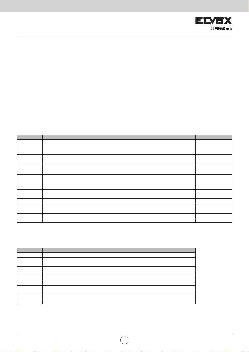
9 - Control panel behaviour when loading settings:
On full uploading of the settings, some parameters are loaded, others maintained and others again are reset.
According to the type of loading, it may be necessary to calibrate the gate travel again.
To know which parameters the control panel loads, which are maintained and which are reset, refer to the table below:
Action Data Control panel behaviour
RESET
(control panel reboot)
Firmware Updating
LOAD MEM
(loading from memory
card)
Reset/Import control
panel data from WiGate app
LOAD DEF
(loading default values)
ERSA
(deletion of receiver
memory)
Fixed counters
Resettable counters
Motor parameters
Gate travel data
Installer settings
Password
Remote controls
Fixed counters
Resettable counters
Motor parameters
Gate travel data
Installer settings
Password
Remote controls
Fixed counters
Resettable counters
Motor parameters Importing data from a MEM.W memory card
Gate travel data Self-calibration on rst manoeuvre
Installer settings
Remote controls
Fixed counters
Resettable counters
Motor parameters Importing data from Wi-Gate app
Gate travel data Self-calibration on rst manoeuvre
Installer settings Importing data from Wi-Gate app
Password
Remote controls
Fixed counters
Motor parameters
Gate travel data Travel data reset, new LRNE or LRNA calibration required
Installer settings
Password
Remote controls No variation
Fixed counters
Resettable counters
Motor parameters
Gate travel data
Installer settings
Password
Remote controls Complete deletion
No variation
No variation
No variation
Importing data from a MEM.W memory cardPassword
No variation
No variation
No variationResettable counters
Restored to DEFAULT
No variation
VIMAR group
EN
19
Page 22

SL24.W
Fixed counters
Resettable counters
Reset/Import receiving
data from Wi-Gate app
10 - Control panel connection from Smartphone/Tablet:
The control panel may be programmed directly from a Smartphone/Tablet without having to interact with the control
panel display or buttons.
Requirements for establishing the connection
- an SL24.W or SW24.W control panel
- an EMC.W Wi-Fi connection module
- an Android device with at least version 4.4 or iOS minimum version 8.0 with the Wi-Gate app installed (download-
able from Google Play or App Store)
- Service access credentials (supplied by Vimar Spa)
To enable the connection check that the EMC.W module is connected to the CNX1 connector and that the parameter
EXP-> CNX1 is set to 1.
Follow the instructions given in the EMC.W module instructions to establish the connection.
Using the Wi-Gate app all the congurations which can be done using the control panel buttons can also be done from
the Smartphone, which however uses full descriptions to make the meaning of the parameters immediately understand-
able.
In addition to connection to the control panel for more immediate and easy conguration, the Wi-Gate app can be used
to save/restore the control panel conguration data on/from a Cloud-based database which can be managed from the
Web portal by accessing the page:
http://wi-gate.vimar.cloud
The installation database management web portal access credentials are the ones used to access the Wi-Gate app.
Here it is possible to manage the records of the saved installations and the access authorisations for the collaborators
of the account holder.
Note: the conguration data of the saved control panels and receivers are not visible from the web interface, they are
physically saved on the cloud but can be retrieved from the cloud and exported onto the control panels only using the
Wi-Gate app.
Motor parameters
Gate travel data
Installer settings
Password
Remote controls Import of remote control list from Wi-Gate app
No variation
20
EN
Page 23

SL24.W
EC DECLARATION OF CONFORMITY
(Declaration of incorporation of partly completed machinery annex IIB 2006/42/EC
No.: ZDT00744.00
The undersigned, representing the following manufacturer Vimar SpA Viale Vicenza 14,
36063 Marostica VI Italy
declares under his own responsibility that the products
Electronic control unit
Trade mark
Elvox SL24.W
Elvox SW24.W
* See www.vimar.com for the full description of the products.
when installed with the appropriate accessories and/or enclosures for devices are in conformity with the provisions of
the following EU directive(s) (including all applicable amendments)
Machinery Directive 2006/42/CE EN 60335-2-103 (2015)
LV Directive 2014/35/EU
R&TTE Directive 1999/5/CE EN 301 489-3 (2013), EN 301 489-17 (2012) EN 300 220-2 (2012),
EN 300 328 (2015)
EMC Directive 2014/30/EU EN 61000-6-2 (2007), EN 61000-6-3 (2007) + A11 (2011)
Further hereby declares that the product must not be put into service until the final machinery into which it is to be
incorporated has been declared in conformity with the provisions of Directive 2006/42/EC, where appropriate.
Declares that the relevant technical documentation is compiled by Vimar SpA and in accordance with part B of Annex
VII of Directive 2006/42/EC and the following essential requirements of this Directive are applied and fulfilled:
1.1.1, 1.1.2, 1.1.3, 1.1.5, 1.1.6, 1.2.1, 1.2.2, 1.2.6, 1.3.1, 1.3.2, 1.3.3, 1.3.4, 1.3.7, 1.3.8, 1.3.9, 1.4.1, 1.4.2, 1.5.1, 1.5.2,
1.5.4, 1.5.5, 1.5.6, 1.5.7, 1.5.8, 1.5.9, 1.6.1, 1.6.2, 1.7.1, 1.7.2, 1.7.3, 1.7.4.
I undertake to make available, in response to a reasoned request by the national authorities, any further supporting
product documents they require.
Type ref.
Cat. ref. Description EN *
SL24.W Control card Wi-Fi 24V sliding gates
SW24.W Control card Wi-Fi 24Vswing gates
Marostica, 6/3/2017 The Managing Director
Note: The contents of this declaration correspond to what declared in the last revision of the ocial declaration available before printing
this manual. The text herein has been re-edited for editorial purposes. A copy of the original declaration can be requested to Vimar SpA
VIMAR group
EN
21
Page 24

SL24.W installer EN 02 1708
Viale Vicenza 14
36063 Marostica VI - Italy
www.vimar.com
 Loading...