

Page 1
RS07
Scheda con trimmer 24 V per cancelli battenti
Board with 24 V trimmer for swing gates
Carte avec trimmer 24 V pour portails à battants
Tarjeta con trimmer 24 V para cancelas batientes
Leiterplatte 24 V mit Trimmer für Flügeltorantrieb
Πλακέτα με trimmer 24 V για ανοιγόμενες καγκελόπορτες
Manuale per il collegamento e l’uso - Installation and operation manual
Manuel pour le raccordement et l’emploi - Installations-und Benutzerhandbuch
Manual para el conexionado y el uso - Εγχειρίδιο σύνδεσης και χρήσης
20 A
CN4CN3CN2CN1 STPA
AC
ON ON
12123 4 5 678
PT1
CN5
FST
VA2
VA1
SEC
TR5
P2 P3
TR1TR2 TR3TR4
FORZA M1 FORZA M2 V.RALL V.MAX
DIP1 DIP2
AP/CH
P1
JP5
U1
U2
CN8 CN6
IBRIDO RX
IBRIDO RX
ENCM1ENCM2
Led
encM1
Led
encM2
APCH APED STOP FOTO
1234
5 678
910111213141516171819
20 21
22 23 24 25 26 27
CN7
F1 (ATO)
F2 (5x20)
F 3.15A
DL6
DL7
2CAN
-SERR
AUX
+VA
-VA
-LAMP
+LAMP
COM1
APCH
APED
COM1
STOP
FOTO
STPA
ANT
APM1
CHM1
APM2
CHM2
+SERR
Page 2
Indice: P a g i n a
Avvertenze per l’installatore
1- Caratteristiche ..................................................................................................................................................................................................1
2- Descrizione della centrale................................................................................................................................................................................1
3- Valutazione dei rischi........................................................................................................................................................................................2
4- Cablaggi elettrici...............................................................................................................................................................................................2
5- Descrizione LED, dip switch e pulsanti su scheda...........................................................................................................................................7
6- Programmazione ............................................................................................................................................................................................8
7- Funzioni programmabili....................................................................................................................................................................................................................................11
8- Installazione batterie....................................................................................................................................................................................................................................11
9- Problemi e soluzioni........................................................................................................................................................................................12
10- Installazione meccanica............................................................................................................................................................................12
AVVERTENZE PER L’INSTALLATORE
- Leggere attentamente le av ver ten ze contenute nel pre sen te do cu men to in quanto for ni sco no importanti indicazioni ri guar dan ti la sicurezza di in stal la zio ne,
d’uso e di ma nu ten zio ne.
-
Dopo aver tolto l’imballaggio assicurarsi dell’integrità del l’ap pa rec chio. Gli ele men ti dell’imballaggio non devono essere lasciati alla portata dei bambini in quanto
potenziali fonti di pericolo. L’esecuzione dell’impianto deve essere ri spon den te alle nor me CEI vigenti.
- Questo ap pa rec chio dovrà essere de sti na to solo all’uso per il quale è stato espres sa men te concepito. Ogni altro uso è da con si de rar si im pro prio e quindi
pericoloso. Il costruttore non può essere con si de ra to re spon sa bi le per even tua li danni derivanti da usi impropri, erronei ed ir ra gio ne vo li.
- Prima di ef fet tua re qual si a si operazione di pu li zia o di ma nu ten zio ne, disinserire l’apparecchio dalla rete di ali men ta zio ne elettrica, spe gnen do l’interruttore
del l’im pian to.
- In caso di guasto e/o di cattivo fun zio na men to del l’ap pa rec chio, togliere l’ali men ta zio ne me dian te l’interruttore e non ma no met ter lo. Per l’even tua le ripa ra zio ne ri vol ger si so la men te ad un centro di assistenza tecnica autorizzato dal costruttore. Il mancato ri spet to di quanto so pra può com pro met te re la
si cu rez za del l’ap pa rec chio.
- Tutti gli apparecchi costituenti l’impianto devono essere de sti na ti esclu si va men te all’uso per cui sono stati con ce pi ti.
- Questo do cu men to dovrà sem pre ri ma ne re allegato alla do cu men ta zio ne dell’impianto.
Direttiva 2002/96/CE (WEEE, RAEE).
Il simbolo del cestino barrato riportato sull’apparecchio indica che il prodotto, alla fine della propria vita utile, dovendo essere trattato separatamente
dai rifiuti domestici, deve essere conferito in un centro di raccolta differenziata per apparecchiature elettriche ed elettroniche oppure riconsegnato al
rivenditore al momento dell’acquisto di una nuova apparecchiatura equivalente.
L’utente è responsabile del conferimento dell’apparecchio a fine vita alle appropriate strutture di raccolta. L’adeguata raccolta differenziata per l’avvio
successivo dell’apparecchio dismesso al riciclaggio, al trattamento e allo smaltimento ambientalmente compatibile contribuisce ad evitare possibili effetti
negativi sull’ambiente e sulla salute e favorisce il riciclo dei materiali di cui è composto il prodotto. Per informazioni più dettagliate inerenti i sistemi di raccolta
disponibili, rivolgersi al servizio locale di smaltimento rifiuti, o al negozio in cui è stato effettuato l’acquisto.
Rischi legati alle sostanze considerate pericolose (WEEE).
Secondo la nuova Direttiva WEEE sostanze che da tempo sono utilizzate comunemente su apparecchi elettrici ed elettronici sono considerate sostanze
pericolose per le persone e l’ambiente. L’adeguata raccolta differenziata per l’avvio successivo dell’apparecchio dismesso al riciclaggio, al trattamento e allo
smaltimento ambientalmente compatibile contribuisce ad evitare possibili effetti negativi sull’ambiente e sulla salute e favorisce il riciclo dei materiali di cui
è composto il prodotto.
Il prodotto è conforme alla direttiva europea 2004/108/CE e successive.
I
Page 3
20 A
CN4CN3CN2CN1 STPA
AC
ON ON
1 21 234 5 678
PT1
CN5
FST
VA2
VA1
SEC
TR5
P2 P3
TR1TR2 TR3TR4
FORZA M1 FORZA M2 V.RALL V.MAX
DIP1 DIP2
AP/CH
P1
JP5
U1
U2
CN8CN6
IBRIDO RX
IBRIDO RX
ENCM1ENCM2
Led
encM1
Led
encM2
APCH APED STOP FOTO
1234
5678
910111213141516171819
20 21
22 23 24 2526 27
CN7
F1 (ATO)
F2 (5x20)
F 3.15A
DL6
DL7
2CAN
-SERR
AUX
+VA
-VA
-LAMP
+LAMP
COM1
APCH
APED
COM1
STOP
FOTO
STPA
ANT
APM1
CHM1
APM2
CHM2
+SERR
1- CARATTERISTICHE
Centrale per il comando per cancelli battenti a 24 Vdc con potenza nominale di 50 W + 50 W, prevista per interfaccia encoder usato per la rilevazione
ostacolo e il controllo di velocità e ricevitore integrato .
La centrale permette:
- di personalizzare lo spazio e la velocità di rallentamento sia in apertura che in chiusura
- dotata di sistema di riconoscimento ostacolo
- LED per la diagnostica ingressi
- memoria dati memorizzati estraibile
- ricevitore integrato con capacità di 200 radiocomandi (a codifica fissa o a rolling-code)
- controllo di corrente per la protezione del motore elettrico
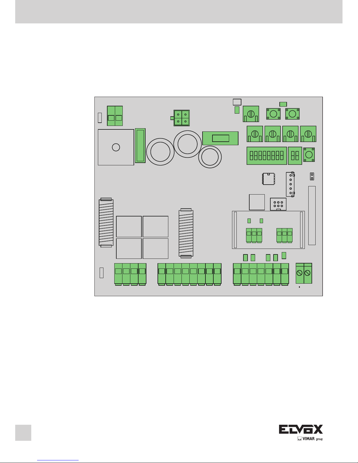
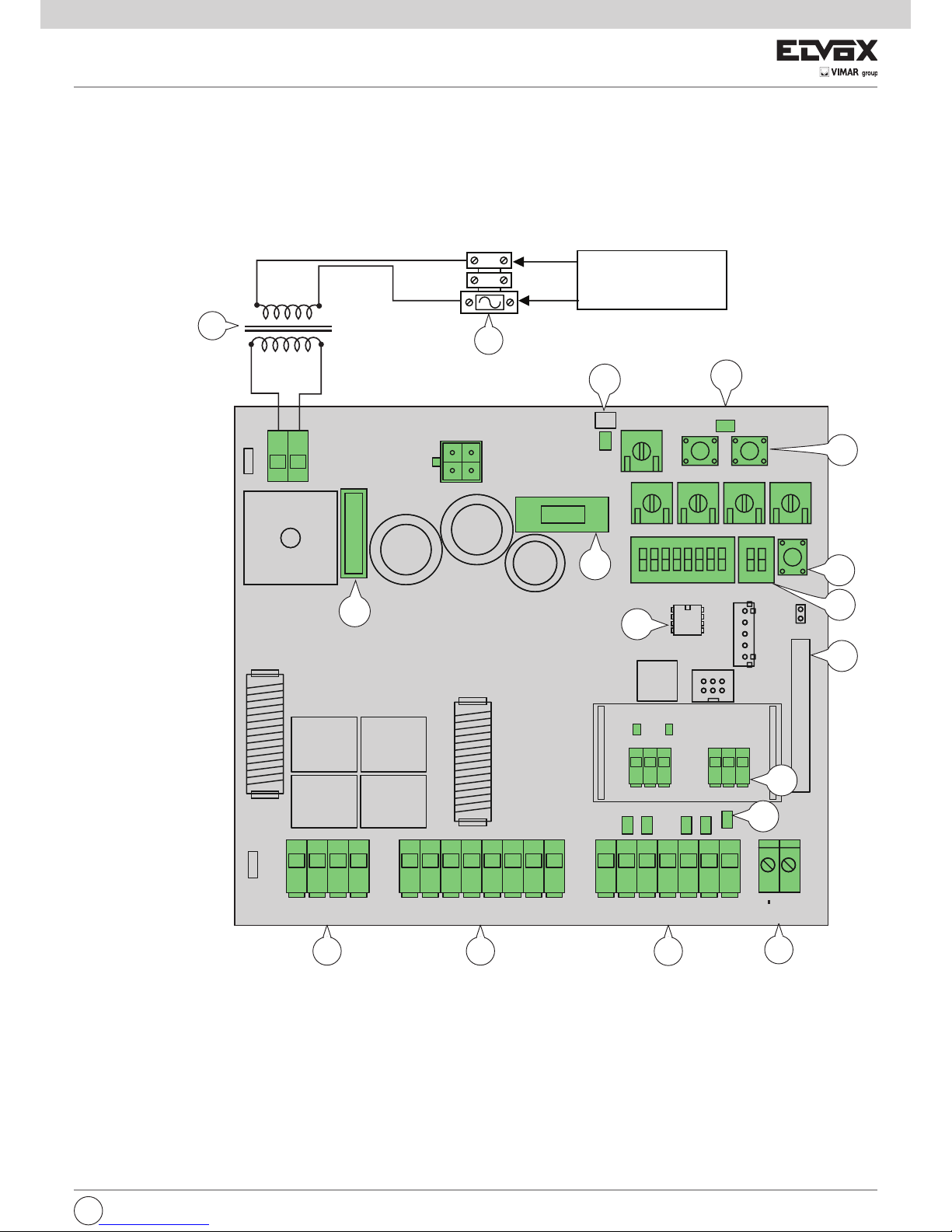
2- DESCRIZIONE DELLA CENTRALE
Legenda:
1- Fusibile primario trasformatore (2 A ritardato)
2- Trasformatore 230/120 Vac - 22 Vac
3- Fusibile protezione del motore 15 A
4- Fusibile protezione accessori 3,15 A
5- LED presenza alimentazione di rete
6- LED diagnosi programmazione
7- Pulsante di comando AP/CH
8- Pulsanti per programmazione
9- Memoria esterna
10- Modulo radio
11- LED diagnostica ingressi
12- Morsetto per il collegamento dell’antenna
13- Dip switch funzioni
14- Interfaccia encoder
15- Morsetto estraibile per il collegamento degli ingressi di comando e sicurezze
16- Morsetto estraibile per ilcollegamento dell’uscita serratura elettrica, alimentazione per accessori, lampeggiante, uscita secondo canale radio e uscita per
spia cancello aperto
17- Morsetto estraibile per il collegamento dell’uscita motore
1
2
Linea
alimentazione
1
4
Fig. 1
I
17
16
15
12
14
8
3
9
11
7
10
5
6
13
Page 4
3- VALUTAZIONE DEI RISCHI
Prima di iniziare l’installazione dell’automatismo è necessario valutare tutti i possibili punti di pericolo presenti durante la movimentazione del cancello, in
figura vengono evidenziati alcuni dei punti di pericolo del cancello battente.
Prima di iniziare l’installazione è necessario controllare la presenza dei fermi meccanici, la loro tenuta e il sistema di sostegno del cancello.
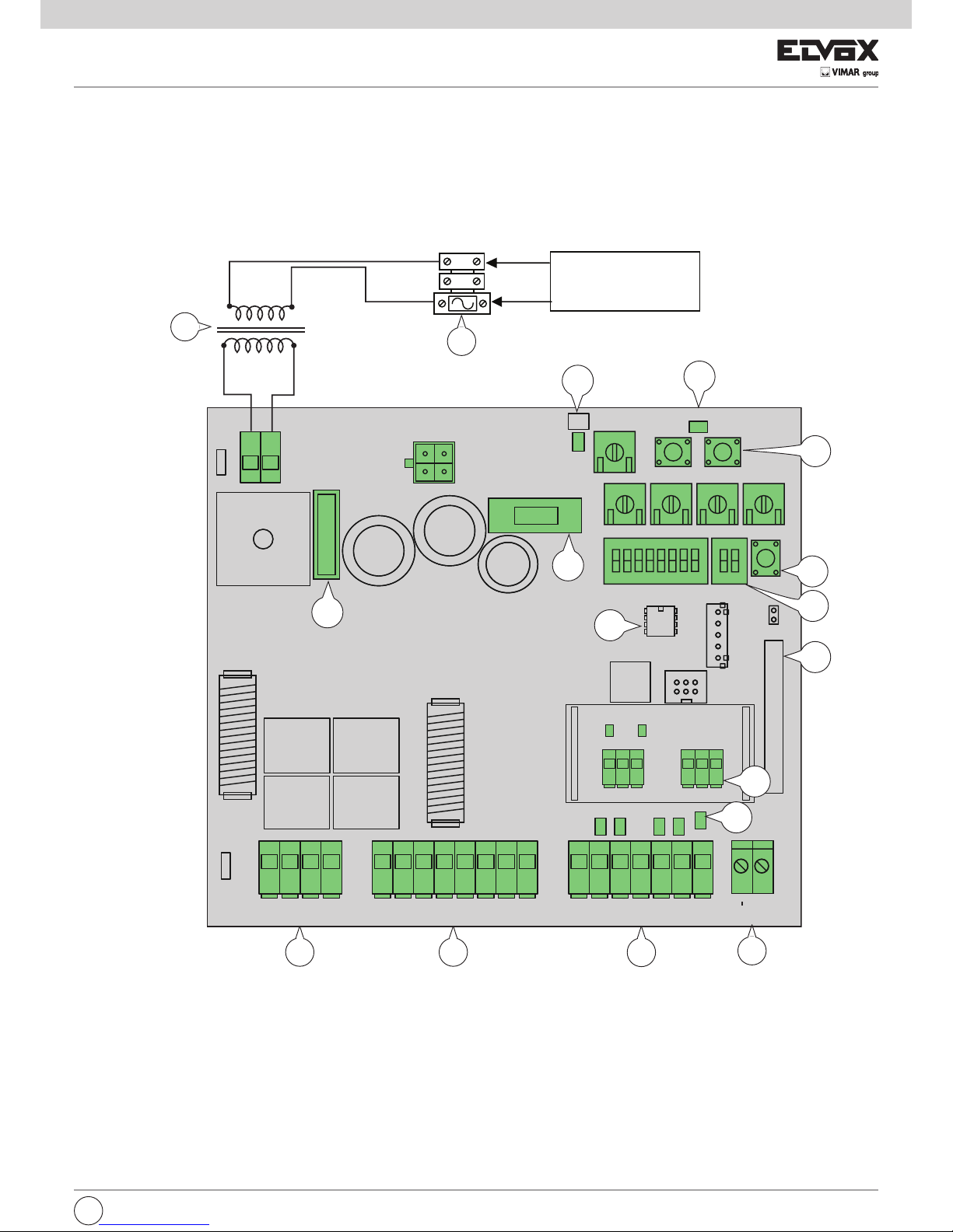
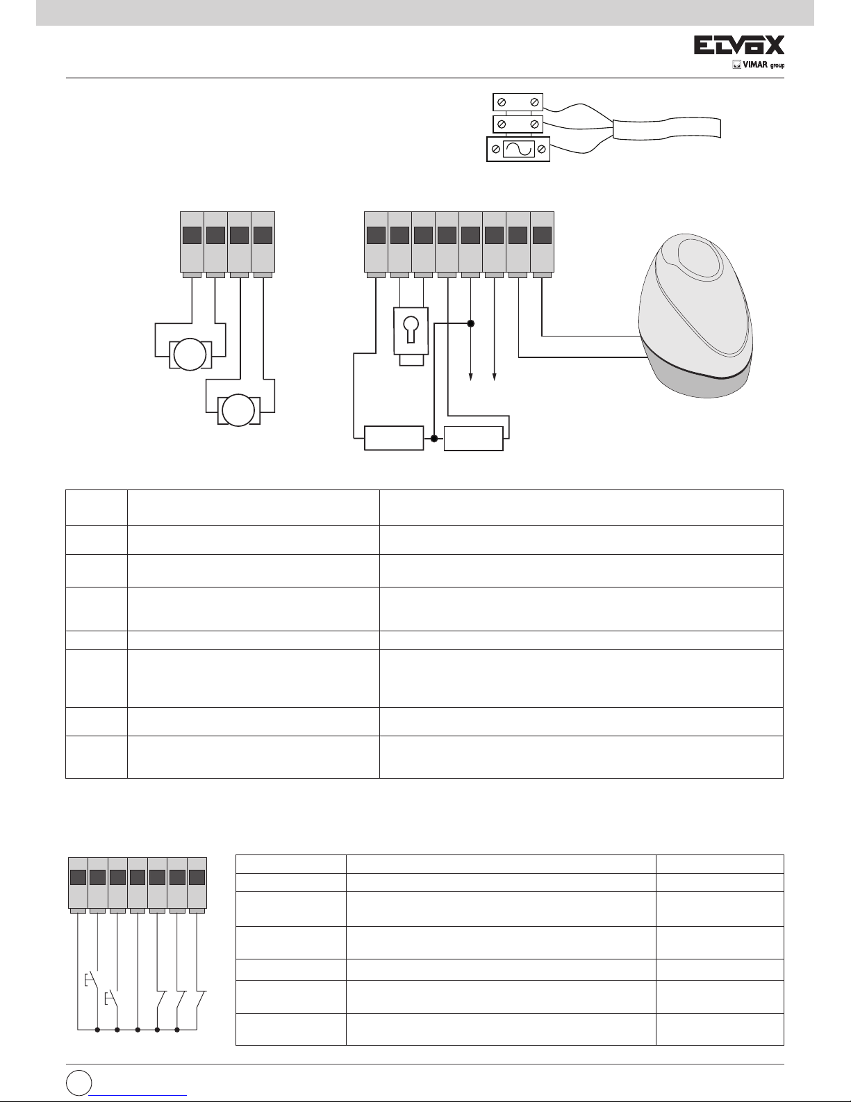
4- CABLAGGI ELETTRICI
Predisposizione impianto
2
Fig. 2
Fig. 3
Legenda
A - Attuatore lineare
B - Centralina di comando
C - Lampeggiante
D - Radiocomando 2 canali
E - Coppia di fotocellule
F - Selettore
G - Elettroserratura
2x0,5 mm
2
2x1 mm
2
3x0,5 mm
2
4x0,5 mm
2
2x0,5 mm
2
2x2,5 mm2 +3x0,5 mm2 (encoder)
2x2,5 mm2 +3x0,5 mm2 (encoder)
3x0,5 mm
2
230/120 Vca
C
B
E
E
A
A
D
F
G
I
Page 5
56 789101112
1234
M
M
4.1- Cablaggio linea alimentazione
All’interno del vano trasformatore è presente un morsetto con fusibile
di protezione da 2 A (collegare la fase nel polo corrispondente al fusibile).
4.2- Cablaggio lampeggiante, luce di cortesia e spia di segnalazione movimento cancello
3
Fig. 5
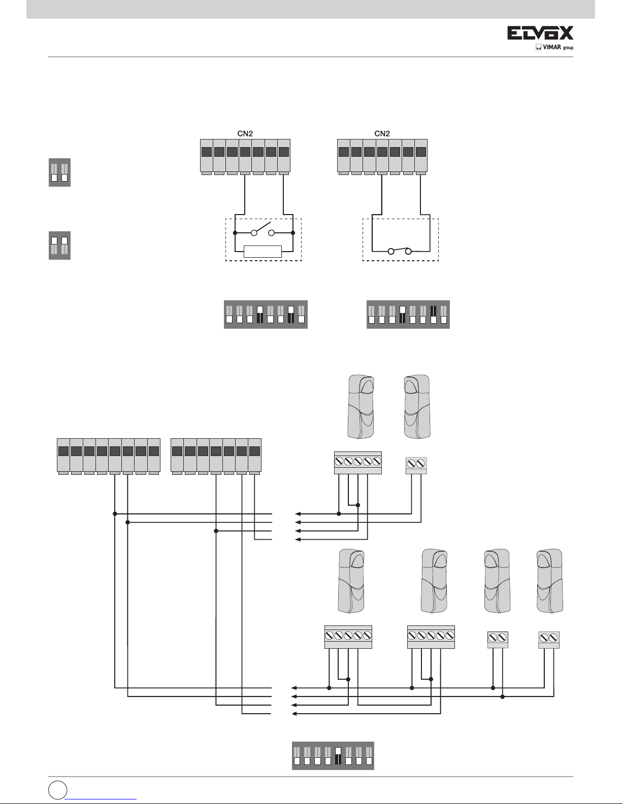
4.3- Collegamenti ingressi:
la centrale viene fornita con gli ingressi normalmente chiusi ponticellati (STOP, FOTO E STPA) togliere il ponte dall’ingresso che si intende utilizzare.
Numero
morsetto
Descrizione Funzione
1-2 Uscita per alimentazione motore elettrico 1
(pedonale)
Uscita per il comando del motore elettrico 1 a 24 Vdc potenza nominale
50 W (1 apertura, 2 chiusura)
3-4 Uscita per alimentazione motore elettrico 2 Uscita per il comando del motore elettrico 2 a 24 Vdc potenza nominale
50 W (3 apertura, 4 chiusura)
5-9 Luce di cortesia o secondo canale radio Uscita a 24 Vdc massimo carico 120 mA, può essere programmata come uscita tem-
porizzata (100 secondi) o uscita secondo canale radio, vedi dip switch numero 6 (5=
GND, 2can/ 9= + 24 Vdc).
6-7 Uscita per comando elettroserratura Uscita per elettroserratura a 12 Vac massimo 15 VA
8-9 Uscita segnalazione movimento cancello
Uscita segnalazione del movimento del cancello, lampeggia lentamente durante l’apertura, accesa fissa a cancello aperto, lampeggia veloce durante la chiusura e spenta a
cancello chiuso (8= GND comandato, 9= + 24 Vdc permanente, massimo carico 120
mA)
9-10 Uscita alimentazione accessori
Uscita a 24 Vdc massimo 300 mA per l’alimentazione delle fotocellule e accessori (9
= + 24 Vdc, 10= GND)
11-12 Uscita per lampeggiante
Uscita a 24 Vdc massimo carico 15W per lampeggiante (11= GND lampeggiante, 12=
+ 24 Vdc) , se la funzione richiusura automatica è attiva il lampeggiante resta acceso a
luce fissa durante il tempo di richiusura automatica.
Numero morsetto Descrizione Tipo ingresso
13-16 Comune ingressi di comando (GND permanente) _
14 Ingresso di comando sequenziale, per il
comando della corsa completa del cancello
Normalmente aperto
15 Ingresso di comando sequenziale, per il
comando della corsa pedonale del cancello
Normalmente aperto
17 Ingresso per arresto del cancello Normalmente chiuso
18 Ingresso fotocellula, attivo durante la
chiusura del cancello
Normalmente chiuso
19 Ingresso bordi o fotocellula interna, attivo durante la
chiusura e l’apertura del cancello
Normalmente chiuso
La somma degli assorbimenti delle uscite 2CAN, AUX e -VA non deve superare i 500 mA.
I
24 Vdc 15 W max
24 Vdc 120 mA max
Luce di cortesia o
secondo canale radio
24 Vdc 120 mA max
spia segnalazione movimento cancello
Uscita alimentazione accessori
24 Vdc 300 mA max
-
+
-
-
-
+
Elettroserratura
12 V 15 VA
Motore 1 Pedonale
Motore 2
13 14 15 16 17 18 19
COM
APCH
APED
COM
STOP
FOTO
STPA
neutro
fase
Terra
Rete
Trasformatore
Fig. 4
Fase
Neutro
Page 6
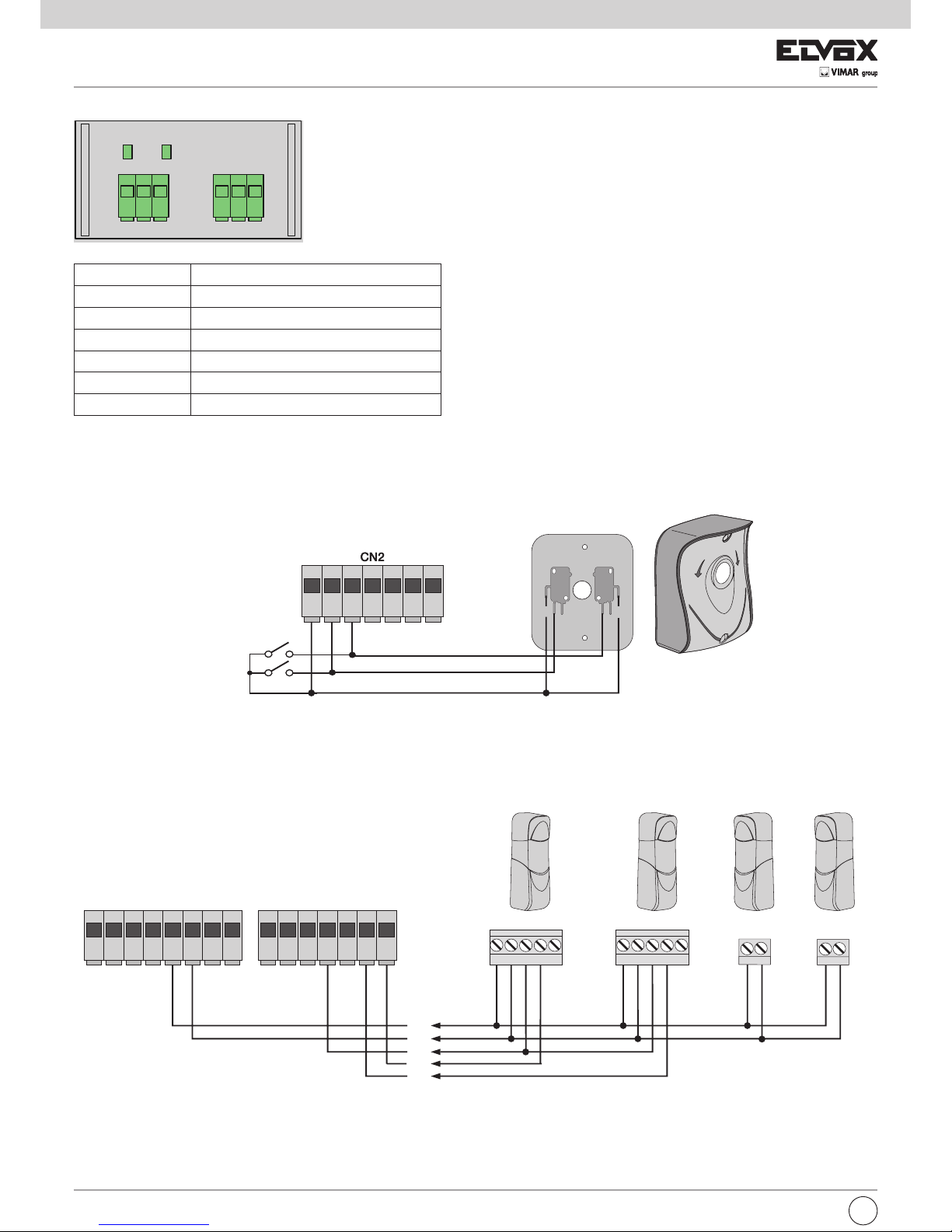
4.4- Collegamento pulsanti di comando e selettore a chiave
Contatti normalmente aperti (i LED rossi AP/CH o APED si accendono quando viene azionato il selettore o i pulsanti collegati in parallelo):
4.5- Collegamento fotocellule
Contatto normalmente chiuso (a fotocellule non impegnate il LED FOTO e il LED STPA devono essere accesi), se non utilizzato fare un ponticello tra
COM. e FOTO e STPA, è necessario rispettare la polarità per l’alimentazione delle fotocellule:
4
Fig. 6
Fig. 7
Collegamento encoder
Numero morsetto Descrizione
22 Ingresso segnale encoder motore 1
23 Negativo alimentazione encoder motore 1
24 Positivo alimentazione encoder motore 1
25 Ingresso segnale encoder motore 2
26 Negativo alimentazione encoder motore 2
27 Positivo alimentazione encoder motore 2
Scheda interfaccia encoder
I
COM COM
N.O. N.O.N.C. N.C.
13 14 15 16 17 18 19
RX1
+-CNCN
A+
-
RX2
+-CNCNA
+-
+
COM
FOTO
-
TX1 TX2
5 6789101112
13 14 15 16 17 18 19
STPA
comando apertura pedonale
comando apertura
AC
ON ON
12123 4 5 678
TR5
P2 P3
TR1TR2 TR3TR4
FORZA M1 FORZA M2 V.RALL V.MAX
DIP1 DIP2
AP/CH
P1
JP5
U1
U2
CN8 CN6
IBRIDO RX
IBRIDO RX
ENCM1ENCM2
Led
encM1
Led
encM2
22 23 24 25 26 27
DL6
EDS1
Page 7
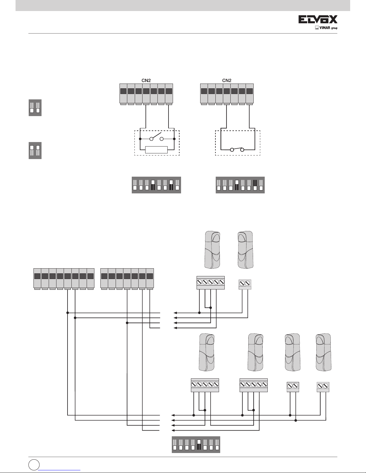
4.6- Collegamento bordo sensibile
(con bordo o fotocellula non impegnato il LED STPA deve essere accesso) l’intervento di questo ingresso, settato come bordo sensibile ha questo effetto:
durante l’apertura inverte immediatamente il movimento per 1,5 secondi e poi arresta il cancello, mentre durante la chiusura inverte il movimento fino alla
completa apertura ingresso programmabile.
Vedere il dip switch 1-4 per selezionare il tipo di bordo settare il dip 1-7 (bordo con contatto normalmente chiuso dip 1-7 in posizione OFF, bordo con resistenza
di bilanciamento da 8,2K ohm dip 1-7 in posizione ON), se non utilizzato fare un ponticello tra COM. e STPA e portare il dip 1-7 in off:
4.7- Collegamento fotocellule con funzione fototest attiva
Nel caso venga attivata la funzione fototest (la centrale verifica il funzionamento delle fotocellule, vedi dip switch 5 in ON), rispettare il seguente collegamento.
A ogni partenza del motore la centrale toglie l’alimentazione al trasmettitore della fotocellula per verificare il loro funzionamento)
5
Collegamento bordo a SwitchCollegamento bordo sensibile resistivo
Fig. 8
Fig. 9
I
COM
FOT
RX
+-CNCNA
+-
TX
RX
+-CNCNA
+-
TX
RX1
+-CNCN
A+
-
RX2
+-CNCNA
+-
TX
1T
X2
+
-
+
-
5 678910111213141516171819
COM
STPA
STPA come
fotocellula interna
COM
FOTO
Ingresso STPA come bordo resi-
stivo a 8,2 KΩ, portare il dip switch
1-4 e 1-7 in posizione ON
13 14 15 16 17 18 19 13 14 15 16 17 18 19
Esempio DIP in posizione ON:
Esempio DIP in posizione OFF:
ON
1 2
ON
1 2
ON
1
2
ON
1 2
ON
1 2
ON
1
2 3 4 5 6 7 8
ON
1 2
ON
1 2
ON
1 2 3 4 5 6 7 8
ON
1
2 3 4 5 6 7 8
DIP 1
DIP 1
ON
1 2
ON
1 2
ON
1 2 3 4 5 6 7 8
ON
1 2 3 4 5 6 7 8
ON
1
2 3 4 5 6 7 8
Ingresso STPA come bordo a switch elettro-
meccanico, portare il dip switch 1-4 in posizione
ON e il dip-switch 1-7 in posizione OFF
8,2 KΩ
Page 8

6
4.8- Collegamento pulsante di arresto
contatto normalmente chiuso, l’apertura del contatto provoca l’arresto del cancello e la sospensione del tempo di richiusura automatica (a pulsante non
impegnato il LED STOP deve essere acceso), se non utilizzato fare un ponticello tra COM. e STOP:
N.B.: se nell’impianto non sono presenti le fotocellule, bordi sensibili o pulsanti di arresto (gli ingressi FOTO, STPA e STOP devono essere ponticellati), non attivare la funzione di fototest e selezionare il bordo a switch (dip switch 1-5 e 1-7 settati in off).
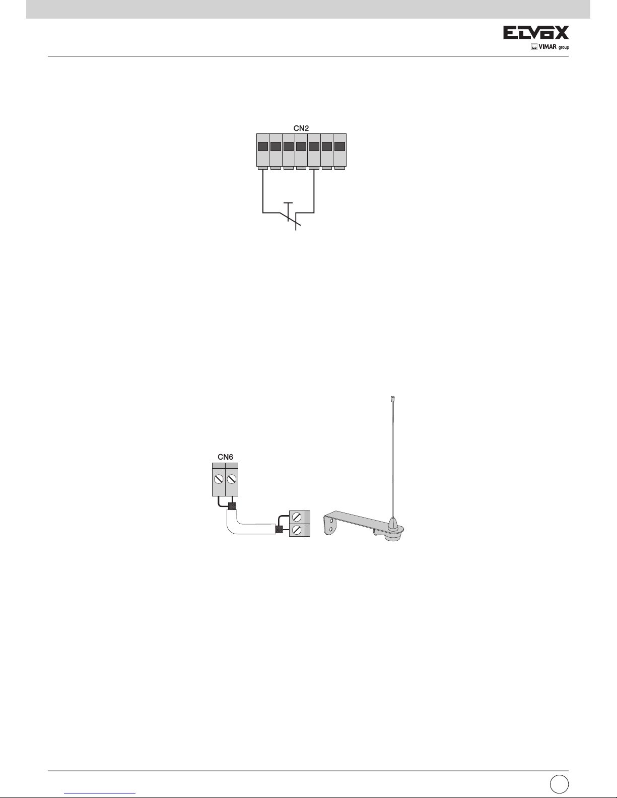
4.9- Collegamento antenna
in dotazione viene fornito il filo rigido di 17 cm già cablato, per aumentare la portata collegare l’antenna ZL43, come riportato in figura:
Pulsante normalmente
chiuso
Fig. 10
Fig. 11
I
13 14 15 16 17 18 19
20 21
Page 9

7
5 - DESCRIZIONE DEI LED E PULSANTI PRESENTI SU SCHEDA
Pulsanti presenti sul circuito
Sigla Descrizione
AP/CH Comanda l’apertura e la chiusura del cancello
P2 Premere per entrare in programmazione della corsa
P3 Premere per entrare in programmazione o cancellazione dei radiocomandi
Controllo preliminare
Dopo aver dato alimentazione alla centrale il LED DL6 si accende con una serie di lampeggi per indicare la versione del firmware. Controllare i LED di diagnostica degli ingressi STOP, FOTO e STPA devono essere accesi .
Sigla Descrizione
AC Visualizza la presenza dell’alimentazione di rete (acceso se presente la tensione di rete)
STPA Visualizza lo stato dell’ingresso STPA (numero 19), se non impegnato il LED resta acceso, se non viene utilizzato ponticellare tra il
morsetto COM e STPA
AP/CH Visualizza lo stato dell’ingresso AP/CH (numero 14), se non impegnato il LED resta spento
APED Visualizza lo stato dell’ingresso APED (numero 15), se non impegnato il LED resta spento
STOP
Visualizza lo stato dell’ingresso STOP (numero 17) , se non impegnato il LED resta acceso, se non viene utilizzato ponticellare tra
il morsetto COM e STOP
FOTO
Visualizza lo stato dell’ingresso FOTO (numero 18), se non impegnato il LED resta acceso, se non viene utilizzato ponticellare tra
il morsetto COM e FOTO.
ENCM1
Visualizza l’ingresso encoder motore 1, acceso fisso durante il movimento del motore a velocità ciclo, lampeggiante durante il rallentamento, spento a motore fermo.
ENCM2
Visualizza l’ingresso encoder motore 2, acceso fisso durante il movimento del motore a velocità ciclo, lampeggiante durante il rallentamento, spento a motore fermo.
DL6 Visualizza lo stato di programmazione della corsa e dell’apprendimento dei radiocomandi
I
Page 10

8
6- PROGRAMMAZIONE
6.1- Procedura rapida per l’apprendimento della corsa per automazioni a doppia anta battente con encoder.
La procedura ridotta permette di memorizzare la corsa, con spazi di rallentamento del 30% rispetto alla corsa totale, mentre i ritardi d’anta vengono fissati a
3 sec in apertura e 6 sec in chiusura.
- Premere il pulsante di apprendimento P2 per almeno 3 secondi
- Il LED DL6 comincia a lampeggiare lentamente
- Rilasciare il pulsante P2
- Attivare APCH:M2 chiude a velocità rallentata fino al fermo meccanico
- M1 chiude a velocità rallentata fino al fermo meccanico
- M1 apre a velocità rallentata fino al fermo meccanico
- M2 apre a velocità rallentata fino al fermo meccanico
- M2 chiude a velocità normale per poi rallentare e continua fino al fermo meccanico in chiusura
- M1 chiude a velocità normale per poi rallentare e continua fino al fermo meccanico in chiusura
- La centrale esegue un ciclo completo di apertura e di chiusura con lo spazio di rallentamento e con gli sfasamenti impostati di
default.
- Il LED DL6 si spegne a conferma della programmazione riuscita.
Con questa programmazione lo spazio di rallentamento è impostato al 30% della corsa memorizzata e un ritardo in apertura pari a 3 secondi e in chiusura
un ritardo di 6 secondi.
N.B.: con questo tipo di programmazione sono necessari i fermi meccanici sia in apertura che in chiusura sia durante la programmazione che nelle ma-
novre normali.
6.2- Procedura rapida per l’ apprendimento della corsa per automazioni a singola anta battente con encoder.
La procedura ridotta permette di memorizzare la corsa, con spazi di rallentamento del 30% rispetto alla corsa totale:
-
Collegare il motore sui morsetti 1 e 2 ( uscita per motore M1) in automatico la centrale si configura per il funzionamento anta singola.
- Premere il pulsante di apprendimento P2 per almeno 3 secondi
- Il LED DL6 comincia a lampeggiare lentamente
- Rilasciare il pulsante P2
- Attivare APCH M1 chiude a velocità rallentata fino al fermo meccanico
- M1 apre a velocità rallentata fino al fermo meccanico
- M1 chiude a velocità normale per poi rallentare e continua fino al fermo meccanico in chiusura
- La centrale esegue un ciclo completo di apertura e di chiusura con lo spazio di rallentamento impostato di default.
- Il LED DL6 si spegne a conferma della programmazione riuscita.
Con questa programmazione lo spazio di rallentamento è impostato al 30% della corsa memorizzata.
N.B.: con questo tipo di programmazione sono necessari i fermi meccanici sia in apertura che in chiusura sia durante la programmazione che nelle manovre
normali. Con la configurazione anta singola il comando pedonale apre per il 50% della corsa totale.
6.3- Procedura completa per l’ apprendimento della corsa per automazioni a doppia anta battente, con encoder.
La procedura completa permette di memorizzare la corsa, con la possibilità di personalizzare lo spazio di rallentamento e lo sfasamento sia in apertura che
in chiusura dei 2 motori.
- Premere il pulsante di apprendimento P2 e mantenerlo premuto
- Il LED DL6 comincia a lampeggiare
- Non rilasciare il pulsante P2 e mantenerlo premuto per altri 2 secondi
- Il LED DL6 comincia a lampeggiare a frequenza più elevata
- Rilasciare il pulsante P2
- Attivare APCH M2 chiude a velocità rallentata fino al fermo meccanico
- M1 chiude a velocità rallentata fino al fermo meccanico
- Parte M1 in apertura a velocità normale
- Quando si decide di cominciare la fase di corsa rallentata attivare APCH
- Inizia la fase di corsa rallentata del motore M1.
- Quando M1 arriva alla totale apertura attivare APCH o aspettare che l’anta arrivi alla battuta meccanica
- la seconda anta M2 si muove in apertura con velocità normale
- Quando si decide di cominciare la fase di corsa rallentata attivare APCH
- Inizia la fase di corsa rallentata del motore M2.
- Quando l’anta arriva alla totale apertura attivare APCH o aspettare che l’anta arrivi alla battuta meccanica
- la seconda anta M2 si muove in chiusura con velocità normale
- Quando si decide di cominciare la fase di corsa rallentata attivare APCH
- Inizia la fase di corsa rallentata del motore M2.
- Quando l’anta arriva sul fermo meccanico di chiusura: la prima anta M1 si muove in chiusura con velocità normale
- Quando si decide di cominciare la fase di corsa rallentata attivare APCH
- Inizia la fase di corsa rallentata del motore M1.
- Quando l’anta arriva sul fermo meccanico di chiusura parte la prima anta M1 in apertura e appena si decide che il tempo di sfasamento dell’anta è sufficiente
attivare nuovamente APCH: parte la seconda anta M2 in apertura
- Completata l’apertura delle 2 ante, parte in chiusura M2 appena si decide che il tempo di sfasamento dell’anta è sufficiente attivare nuovamente APCH
si muove la prima anta M1 in chiusura.
- Completata la chiusura delle 2 ante, il LED DL6 si spegne a conferma della programmazione riuscita.
N.B.: con questo tipo di programmazione sono necessari i fermi meccanici in chiusura sia durante la programmazione che nelle manovre normali
I
Page 11

9
6.4- Procedura completa per l’ apprendimento della corsa per automazioni a singola anta battente, con encoder.
La procedura completa permette di memorizzare la corsa, con la possibilità di personalizzare lo spazio di rallentamento.
-
Collegare il motore sui morsetti 1 e 2 (uscita per motore M1) in automatico la centrale si configura per il funzionamento anta singola.
- Premere il pulsante di apprendimento P2 e mantenerlo premuto
- Il LED DL6 comincia a lampeggiare
- Non rilasciare il pulsante P2 e mantenerlo premuto per altri 2 secondi
- Il LED DL6 comincia a lampeggiare a frequenza più elevata
- Rilasciare il pulsante P2
- Attivare APCH M1 chiude a velocità rallentata fino al fermo meccanico
- Parte M1 in apertura a velocità normale
- Quando si decide di cominciare la fase di corsa rallentata attivare APCH
- Inizia la fase di corsa rallentata del motore M1.
- Quando M1 arriva alla totale apertura attivare APCH o aspettare che l’anta arrivi alla battuta meccanica
- La prima anta M1 si muove in chiusura con velocità normale
- Quando si decide di cominciare la fase di corsa rallentata attivare APCH
- Inizia la fase di corsa rallentata del motore M1.
- Completata la chiusura dell’anta, il LED DL6 si spegne a conferma della programmazione riuscita.
N.B.: con questo tipo di programmazione sono necessari i fermi meccanici in chiusura sia durante la programmazione che nelle manovre normali. Con la
configurazione anta singola il comando pedonale apre per il 50% della corsa totale.
Per la programmazione della corsa senza encoder, sfilare la scheda interfaccia encoder.
6.5- Procedura rapida per l’apprendimento della corsa per automazioni a doppia anta battente, senza encoder.
La procedura ridotta permette di memorizzare la corsa, con spazi di rallentamento del 30% rispetto alla corsa totale, mentre i ritardi d’anta vengono fissati a
3 sec in apertura e 6 sec in chiusura.
- Premere il pulsante di apprendimento P2 per almeno 3 secondi
- Il LED DL6 comincia a lampeggiare lentamente
- Rilasciare il pulsante P2
- Attivare APCH M2 chiude a velocità normale fino al fermo meccanico
- M1 chiude a velocità normale fino al fermo meccanico
- M1 apre a velocità normale fino al fermo meccanico
- M2 apre a velocità normale fino al fermo meccanico
- M2 chiude a velocità normale fino al fermo meccanico in chiusura
- M1 chiude a velocità normale fino al fermo meccanico in chiusura
- La centrale esegue un ciclo completo di apertura e di chiusura con lo spazio di rallentamento e con gli sfasamenti impostati di default.
- Il LED DL6 si spegne a conferma della programmazione riuscita.
Con questa programmazione lo spazio di rallentamento è impostato al 30% della corsa memorizzata, il ritardo in apertura pari a 3 secondi e in chiusura un
ritardo di 6 secondi.
N.B.: con questo tipo di programmazione sono necessari i fermi meccanici sia in apertura che in chiusura sia durante la programmazione che nelle ma-
novre normali.
6.6- Procedura rapida per l’apprendimento della corsa per automazioni a singola anta battente, senza encoder.
La procedura ridotta permette di memorizzare la corsa, con spazi di rallentamento del 30% rispetto alla corsa totale:
- Collegare il motore sui morsetti 1 e 2 (uscita per motore M1) in automatico la centrale si configura per il funzionamento anta singola.
- Premere il pulsante di apprendimento P2 per almeno 3 secondi
- Il LED DL6 comincia a lampeggiare lentamente
- Rilasciare il pulsante P2
- Attivare APCH:M1 chiude a velocità normale, fino al fermo meccanico
- M1 apre a velocità normale, fino al fermo meccanico
- M1 chiude a velocità normale, fino al fermo meccanico in chiusura
- La centrale esegue un ciclo completo di apertura e di chiusura con lo spazio di rallentamento impostato di default.
- Il LED DL6 si spegne a conferma della programmazione riuscita.
Con questa programmazione lo spazio di rallentamento è impostato al 30% della corsa memorizzata.
N.B.: con questo tipo di programmazione sono necessari i fermi meccanici sia in apertura che in chiusura sia durante la programmazione che nelle manovre
normali. Con la configurazione anta singola il comando pedonale apre per il 50% della corsa totale.
I
Page 12

10
6.7- Procedura completa per l’ apprendimento della corsa per automazioni a doppia anta battente, senza encoder.
La procedura completa permette di memorizzare la corsa, con la possibilità di personalizzare lo spazio di rallentamento e lo sfasamento sia in apertura che
in chiusura dei 2 motori
- Premere il pulsante di apprendimento P2 e mantenerlo premuto
- Il LED DL6 comincia a lampeggiare
- Non rilasciare il pulsante P2 e mantenerlo premuto per altri 2 secondi
- Il LED DL6 comincia a lampeggiare a frequenza più elevata
- Rilasciare il pulsante P2
- Attivare APCH: M2 chiude a velocità normale, fino al fermo meccanico
- M1 chiude a velocità normale, fino al fermo meccanico
- Parte M1 in apertura a velocità normale
- Quando si decide di cominciare la fase di corsa rallentata attivare APCH
- Inizia la fase di corsa rallentata del motore M1.
- Quando M1 arriva alla battuta meccanica, la seconda anta M2 si muove in apertura con velocità normale
- Quando si decide di cominciare la fase di corsa rallentata attivare APCH
- Inizia la fase di corsa rallentata del motore M2.
- Quando l’anta arriva alla battuta meccanica, la seconda anta M2 si muove in chiusura con velocità normale
- Quando si decide di cominciare la fase di corsa rallentata attivare APCH
- Inizia la fase di corsa rallentata del motore M2.
- Quando l’anta arriva sul fermo meccanico di chiusura: la prima anta M1 si muove in chiusura con velocità normale
- Quando si decide di cominciare la fase di corsa rallentata attivare APCH
- Inizia la fase di corsa rallentata del motore M1.
- Quando l’anta arriva sul fermo meccanico di chiusura parte la prima anta M1 in apertura e appena si decide che il tempo di sfasamento dell’anta è suffi-
ciente attivare nuovamente APCH: parte la seconda anta M2 in apertura
- Completata l’apertura delle 2 ante, parte in chiusura M2 appena si decide che il tempo di sfasamento dell’anta è sufficiente attivare nuovamente APCH:
si muove la prima anta M1 in chiusura.
- Completata la chiusura delle 2 ante, il LED DL6 si spegne a conferma della programmazione riuscita.
N.B.: con questo tipo di programmazione sono necessari i fermi meccanici in chiusura sia durante la programmazione che nelle manovre normali.
6.8- Procedura completa per l’ apprendimento della corsa per automazioni a singola anta battente, senza encoder.
La procedura completa permette di memorizzare la corsa, con la possibilità di personalizzare lo spazio di rallentamento.
-
Collegare il motore sui morsetti 1 e 2 (uscita per motore M1) in automatico la centrale si configura per il funzionamento anta singola
.
- Premere il pulsante di apprendimento P2 e mantenerlo premuto
- Il LED DL6 comincia a lampeggiare
- Non rilasciare il pulsante P2 e mantenerlo premuto per altri 2 secondi
- Il LED DL6 comincia a lampeggiare a frequenza più elevata
- Rilasciare il pulsante P2
- Attivare APCH: M1 chiude a velocità normale, fino al fermo meccanico
- Parte M1 in apertura a velocità normale
- Quando si decide di cominciare la fase di corsa rallentata attivare APCH
- Inizia la fase di corsa rallentata del motore M1.
- Quando M1 arriva alla battuta meccanica di apertura
- La prima anta M1 si muove in chiusura con velocità normale
- Quando si decide di cominciare la fase di corsa rallentata attivare APCH
- Inizia la fase di corsa rallentata del motore M1.
- Completata la chiusura dell’anta, il LED DL6 si spegne a conferma della programmazione riuscita.
N.B.: con questo tipo di programmazione sono necessari i fermi meccanici in chiusura sia durante la programmazione che nelle manovre normali. Con la
configurazione anta singola il comando pedonale apre per il 50% della corsa totale.
6.9- Programmazione o cancellazione dei radiocomandi
Memorizzare il tasto del radiocomando per comandare l’ingresso AP/CH: premere il tasto P3 fino a quando il LED DL6 a luce verde inizia a lampeggiare
lentamente, rilasciare il tasto e premere il pulsante del radiocomando da memorizzare, il LED DL6 si accende con colore verde per 1 secondo, per confermare
la memorizzazione avvenuta. Per memorizzare altri radiocomandi, ripetere la procedura descritta.
Memorizzare il tasto del radiocomando per comandare l’ingresso APED: premere il tasto P3 fino a quando il LED DL6 a luce verde inizia a lampeggiare
velocemente, rilasciare il tasto e premere il pulsante del radiocomando da memorizzare, il LED DL6 si accende con colore verde per 1 secondo per confermare
la memorizzazione avvenuta del tasto del radiocomando che aziona l’apertura pedonale. Per memorizzare altri radiocomandi, ripetere la procedura descritta.
Per cancellare un radiocomando memorizzato: premere il tasto P3 fino a quando il LED DL6 a luce verde inizia a lampeggiare molto velocemente, rilasciare
il tasto e premere il pulsante del radiocomando da cancellare, il LED DL6 si accende con colore verde per 1 secondo per confermare la cancellazione del
tasto del radiocomando. Per cancellare altri radiocomandi, ripetere la procedura descritta.
Per cancellare di tutti i radiocomandi: togliere l’alimentazione alla centrale, scollegare anche le eventuali batterie se presenti.
Premere e tenere premuto il tasto P3, ridare alimentazione alla centrale senza rilasciare il tasto P3 fino allo spegnimento del LED DL6.
La capacità massima è di 200 radiocomandi, al raggiungimento della capacità massima entrando in memorizzazione del radiocomando (il LED verde DL6
lampeggia) alla pressione del tasto del nuovo trasmettitore da memorizzare, il LED verde DL6 esegue 3 lampeggi veloci, per indicare la saturazione della
memoria.
N.B.: il primo radiocomando memorizzato configura la centrale per accettare solo i radiocomandi con codifica rolling-code o solo radiocomandi
con codifica fissa a 12 bit.
I
Page 13
11
7 - FUNZIONI PROGRAMMABILI
La tabella riporta le funzioni attivabili tramite i dip switch, la centrale và a leggere i dip a cancello fermo in chiusura:
Numero dip switch Stato del dip Descrizione
DIP 1-1 OFF Funzione di richiusura automatica non attiva
DIP 1-1 ON Funzione di richiusura automatica attiva
DIP 1-2 OFF Funzione condominiale attiva (durante l’apertura del cancello, non è possibile fermare il movimento tramite il
radio-comando o l’ingresso AP/CH)
DIP 1-2 ON A ogni comando il cancello esegue: apertura, arresto . chiusura e arresto
DIP 1-3 OFF Prelampeggio non attivo
DIP 1-3 ON Prelampeggio attivo, prima del movimento del cancello il lampeggiante si accende per 3 secondi
DIP 1-4 OFF Ingresso stpa come fotocellula interna
DIP 1-4 ON Ingresso stpa come bordo sensibile
DIP 1-5 OFF Funzione fototest non attiva
DIP 1-5 ON Funzione fototest attiva (verifica il funzionamento delle fotocellula a ogni comando)
DIP 1-6 OFF Secondo canale radio associato al comando dell’apertura pedonale e uscita 2CAN funziona come luce di corte-
sia (a ogni movimento del cancello resta accesa per 100 sec.)
DIP 1-6 ON Secondo canale radio associanto all’attivazione per 1 secondo dell’uscita 2CAN (morsetto 5 e 9)
DIP 1-7 OFF Bordo sensibile con contatto normalmente chiuso
DIP 1-7 ON Bordo sensibile resistivo, contatto normalmente aperto con resistenza di bilanciamento di 8,2 K Ohm in parallelo
DIP 1-8 OFF Funzione chiudi subito non attiva
DIP 1-8 ON Abilita la funzione chiudi subito (l’intervento della fotocellula porta il tempo di richiusura automatica a 5 secondi,
al suo disimpegno)
DIP 2-1 OFF Funzione colpo d’ariete per elettroserratura non attiva
DIP 2-1 ON
Funzione colpo d’ariete per elettroserratura attiva
(facilita lo sgancio e il riarmo dell’elettroserratura)
DIP 2-2 OFF Non usato
DIP 2-2 ON Non usato
Trimmer per regolazione:
Trimmer Descrizione
TR1 Forza M1 ( regola la coppia del motore M1 pedonale)
TR2 Forza M2 ( regola la coppia del motore M2)
TR3 Velocità di rallentamento
TR4 Velocità di ciclo
TR5 Tempo di richiusura automatica ( regolabile da 2 a 120 secondi)
N.B. : variando i trimmer TR3 ( velocità rallentamento) o TR4 ( velocità ciclo) il LED rosso DL6 lampeggia velocemente, dare un comando con il tasto APCH.
Il cancello esegue una apertura e una chiusura completa per memorizzare gli assorbimenti durante la corsa con le nuove velocità, a chiusura completata il
LED DL6 si spegne, memorizzando i nuovi valori.
La centrale è dotata di un sistema di riconoscimento ostacoli:
- con ostacolo durante l’apertura, il cancello si ferma e richiude per 1 secondo la richiusura automatica resta attiva
- con ostacolo durante la chiusura, il cancello si ferma e riapre completamente, la richiusura automatica resta attiva, nel caso in cui la centrale rileva 5 ostacoli
consecutivi durante la chiusura, il cancello si apre e resta fermo aperto, dopo di che è necessario un comando APCH, il cancello si richiude con velocità
ridotta fino al fermo meccanico.
Le segnalazioni di errore vengono visualizzate tramite il LED DL6 e il lampeggiante (morsetto numero 11 e 12) dopo un comando di apertura.
Leggenda messaggio di anomalia:
8 - INSTALLAZIONE BATTERIE
Inserire nel connettore CN7 il circuito di carica batteria e collegare le batterie, con il funzionamento solo a batteria la velocità del motore è 15% inferiore
rispetto la velocità con alimentazione di rete. Con il funzionamento solo a batterie il LED AC si spegne, l’uscita 2CAN e AUX e l’uscita per lampeggiante non
sono attive e gli accessori sono alimentati solo durante il movimento delle ante.
N.B.: con il funzionamento tramite batterie e in assenza di tensione di rete, le ante si muovono una alla volta sia in apertura che in chiusura senza rallentare.
Numero di lampeggi Descrizione
2 Test fotocellule fallito (cablaggio errato o fotocellule occupate)
3 Rilevato un problema sul circuito che attiva il motore 1
4 Rilevato un problema sul circuito che attiva il motore 2
5 Problema su encoder M1(encoder M1 danneggiato o cablaggio encoder errato)
6 Problema su encoder M2(encoder M2 danneggiato o cablaggio encoder errato)
7 Errore grave su EEPROM (componente U2 non presente o danneggiato)
8 Esaurito il tempo previsto per il termine della corsa( motoriduttore sbloccato o danneggiato)
9 Fusibile F2 rotto
10 Errore sovracorrente motore M1
11 Errore sovracorrente motore M2
I
Page 14
12
9 - PROBLEMI E SOLUZIONI
Problema Causa Soluzione
L’automazione non funziona Manca alimentazione di rete
Fusibili bruciati
Ingressi di comando e sicurezza non funzionanti
Controllare interruttore della linea di alimentazione
Sostituire i fusibili con lo stesso valore
Controllare i LED di diagnostica (STOP, STPA e
FOTO, devono essere accesi)
Non si riesce a memorizzare i radiocomandi
Sicurezze aperte
Batterie del radiocomando scariche
Radiocomando non compatibile con il primo memorizzato
Raggiunto la saturazione della memoria
Controllare i LED di diagnostica (STOP, STPA e
FOTO, devono essere accesi)
Sostituire le batterie
Il primo radiocomando memorizzato configura la
centrale per memorizzare solo radiocomandi a
rolling code o solo radiocomandi a dip.
Eliminare almeno un radiocomando o aggiungere
un ricevitore esterno (capacità massimo 200 radiocomandi)
Appena parte il cancello si ferma e inverte Coppia del motore non sufficiente Aumentare la forza tramite il trimmer TR1 per mo-
tore M1 e TR2 per M2
Durante il rallentamento il cancello si ferma
ed inverte
Velocità rallentamento troppo bassa Aumentare il valore del trimmer TR3
Movimento di uno dei 2 motori risulta invertito
Cablaggio errato Controllare il cablaggio dei motori (1= apre M1/2=
chiude M1/3= apre M2/ 4= chiude M2)
Durante la taratura il motore M1 parte e si ferma
dopo 1 secondo
Cablaggio encoder 1 invertito con encoder 2 Controllare il cablaggio encoder
Con elettroserratura il motore 1 non riesce partire in apertura o non chiude totalmente
Elettroserratura non si riarma Portare il dip 2-1 in posizione on (funzione di ag-
gancio sgancio elettroblocco)
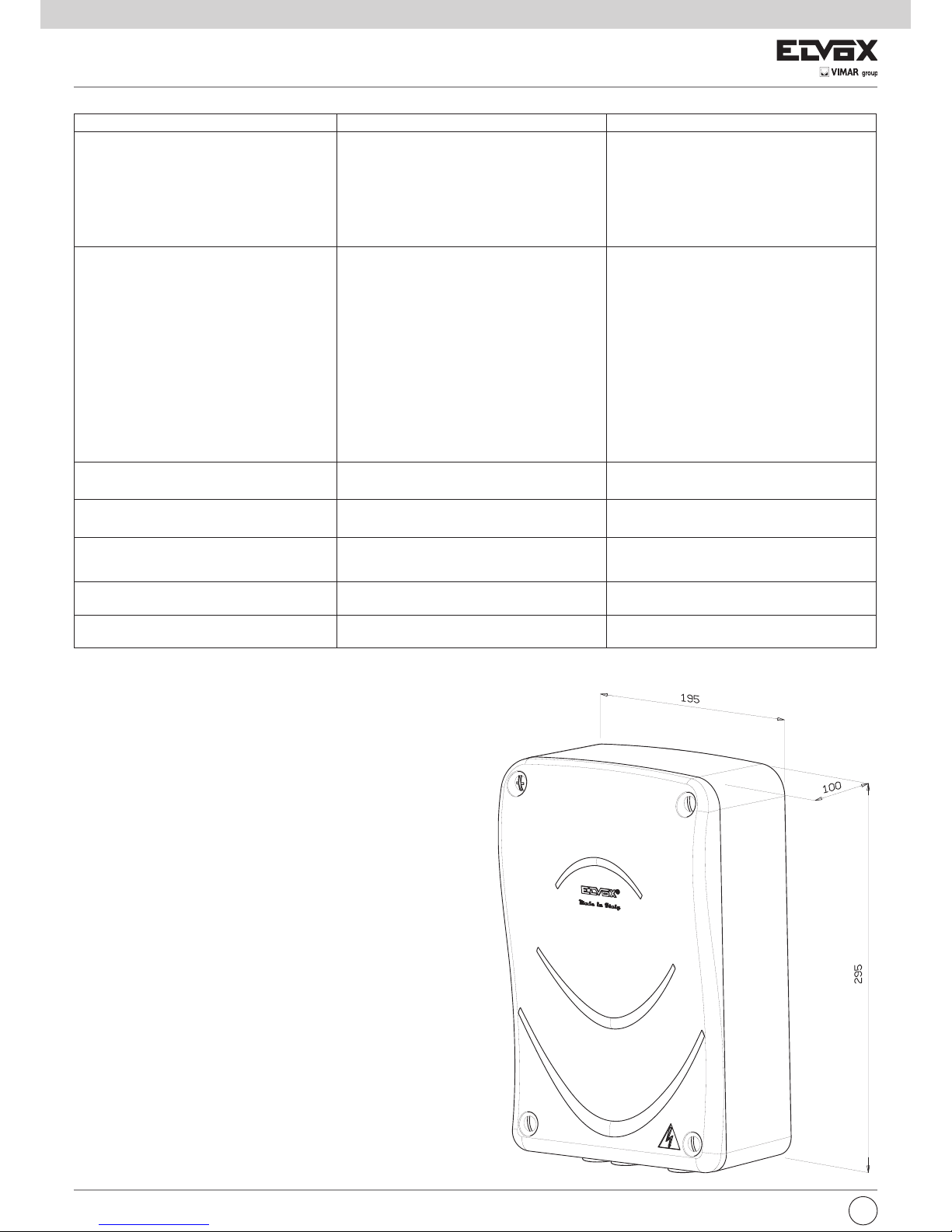
Misure di ingombro centralina:
10 - INSTALLAZIONE MECCANICA
Per una corretta installazione fissare il box in un luogo sicuro e al
riparo dagli agenti atmosferici. Per fissare il box nella parete bisogna
togliere le 4 viti in plastica e aprire il coperchio.
I
Page 15

DICHIARAZIONE CE DI CONFORMITÀ
(Dichiarazione di incorporazione di quasi-macchine allegato IIB Direttiva 2006/42/CE)
No.:ZDT00434.00
Il sottoscritto, rappresentante il seguente costruttore
Elvox SpA
Via Pontarola, 14/A - 35011 Campodarsego
(PD) Italy
dichiara qui di seguito che i prodotti
SCHEDA DI COMANDO - SERIE RS
Articoli RS01, RS02, RS03, RS04, RS05, RS06, RS07, RS08, RS12, RS13, RS14
risultano in conformità a quanto previsto dalla(e) seguente(i) direttiva(e) comunitaria(e) (comprese tutte le modifiche applicabili)
e che sono state applicate tutte le seguenti norme e/o specifiche tecniche
Direttiva EMC 2004/108/CE: EN 61000-6-1 (2007), EN 61000-6-3 (2007) + A1 (2011)
Direttiva R&TTE 1999/5/CE: EN 301 489-3 (2002), EN 300 220-3 (2000)
Direttiva Macchine 2006/42/CE EN 60335-2-103 (2003) + A11 (2009),
EN 13241 (2003) + A1 (2011), EN 12453 (2000)
Dichiara inoltre che la messa in servizio del prodotto non deve avvenire prima che la macchina finale, in cui deve essere incorporato, non è stata dichiarata conforme, se del caso, alle disposizioni della Direttiva 2006/42/CE.
Dichiara che la documentazione tecnica pertinente è stata costituita da Elvox SpA, è stata compilata in conformità all’allegato
VIIB della Direttiva 2006/42/CE e che sono stati rispettati i seguenti requisiti essenziali: 1.1.1, 1.1.2, 1.1.3, 1.1.5, 1.1.6, 1.2.1,
1.2.2, 1.2.6, 1.3.1, 1.3.2, 1.3.3, 1.3.4, 1.3.7, 1.3.8, 1.3.9, 1.4.1, 1.4.2, 1.5.1, 1.5.2, 1.5.4, 1.5.5, 1.5.6, 1.5.7, 1.5.8, 1.5.9, 1.6.1.,
1.6.2, 1.7.1, 1.7.2, 1.7.3, 1.7.4.
Si impegna a presentare, in risposta ad una richiesta adeguatamente motivata delle autorità nazionali, tutta la necessaria
documentazione giustificativa pertinente al prodotto.
Campodarsego, 29/04/2013
L’Amministratore Delegato
Nota: Il contenuto di questa dichiarazione corrisponde a quanto dichiarato nell’ultima revisione della dichiarazione ufficiale disponibile prima
della stampa di questo manuale. Il presente testo è stato adattato per motivi editoriali. Copia della dichiarazione originale può essere richiesta a
Elvox SpA
I
Page 16

14
Contents: P a g e
Warnings for the installer
1- Characteristics ..................................................................................................................................................................................................15
2- Description of the control panel................................................................................................................................................................................15
3- Risk assessment........................................................................................................................................................................................16
4- Electrical wiring harnesses...............................................................................................................................................................................................16
5- Description of LEDs, dip switches and buttons on board.................................................................................................................................................................................21
6- Programming ...................................................................................................................................................................................................22
7- Programmable functions..................................................................................................................................................................................25
8- Installing batteries..........................................................................................................................................................................................25
9- Troubleshooting........................................................................................................................................................................................26
10- Mechanical installation.....................................................................................................................................................................................................26
WARNINGS FOR THE INSTALLER
- Carefully read all instructions and warnings in this document as they provide important information regarding safety during installation, operation and
maintenance.
-
After removing the packaging, check the condition of the device. Packaging materials must be kept out of the reach of children as they constitute a hazard.
System installation must comply with current CEI standards.
- This device must only be used for the purpose for which it was expressly designed. Any other use is considered improper and therefore hazardous. The
manufacturer declines all liability for damage caused by improper, incorrect or unreasonable use.
- Always disconnect the equipment from the power supply by means of the main switch before performing maintenance or cleaning procedures.
- In the event of faults and/or malfunctions, disconnect the device from the power supply immediately by means of the switch and do not tamper with any of
its parts. For repairs, only contact service centres authorised by the manufacturer. Failure to observe the above may impair equipment safety.
- All apparatus within the system must be used exclusively for the purpose for which it was designed.
- This document must always be kept with all paperwork regarding the installation.
2002/96/EC Directive (WEEE, RAEE).
The crossed-out dustbin symbol on the equipment indicates that the product, at the end of its useful working life, must be disposed of separately from
normal household waste, and as such must be taken to a waste separation and recycling centre equipped to deal with electric and electronic equipment
or sent back to the dealer when new replacement equipment is purchased.
The user is responsible for ensuring the equipment is disposed of via the correct channels when it is no longer in working order. Suitable separated
waste collection for subsequent recycling, processing and environmentally conscious disposal of the old appliance helps to prevent negative impact on the
environment and human health while encouraging recycling of the materials used to build the product. For more detailed information regarding the available
waste collection systems, contact your local waste disposal service or the shop from which the equipment was purchased.
Risks associated with substances considered hazardous (WEEE).
According to the new WEEE Directive, substances which for some time have been widely used in electrical and electronic equipment are considered
hazardous to human health and the environment. Suitable separated waste collection for subsequent recycling, processing and environmentally conscious
disposal of the old appliance helps to prevent negative impact on the environment and human health while encouraging recycling of the materials used to
build the product.
The product complies with the European Directive 2004/108/EC and subsequent amendments.
EN
Page 17
15
1- CHARACTERISTICS
Control panel for governing 24 Vdc swing gates with 50 W + 50 W rated power, equipped with encoder interface used for obstacle detection and speed
control and integrated receiver.
The control panel enables:
- customizing the space and speed of deceleration in both opening and closing phases
- equipped with obstacle detection system
- LED for input diagnostics
- removable saved data memory
- integrated receiver with capacity for 200 remote controls (hard coded or rolling code)
- current control for electric motor protection
2- DESCRIPTION OF THE CONTROL PANEL
Key:
1- Transformer primary fuse (2 A delayed)
2- Transformer 230/120 Vac - 22 Vac
3- 15 A fuse protecting motor
4- 3.15 A fuse protecting accessories
5- LED signalling mains power supply
6- LED for programming diagnosis
7- AP/CH control button
8- Programming buttons
9- External memory
10- Radio module
11- LED for input diagnostics
12- Terminal for aerial connection
13 - Functions dip switches
14- Encoder interface
15- Removable terminal for connecting safety and control inputs
16- Removable terminal for connecting electric lock, power supply for accessories, flashing light, second radio channel output and gate open warning light
output
17- Removable terminal for connecting the motor output
Fig. 1
EN
20 A
CN4CN3CN2CN1 STPA
AC
ON ON
1 21 234 5 678
PT1
CN5
FST
VA2
VA1
SEC
TR5
P2 P3
TR1TR2 TR3TR4
FORZA M1 FORZA M2 V.RALL V.MAX
DIP1 DIP2
AP/CH
P1
JP5
U1
U2
CN8CN6
IBRIDO RX
IBRIDO RX
ENCM1ENCM2
Led
encM1
Led
encM2
APCH APED STOP FOTO
1234
5678
910111213141516171819
20 21
22 23 24 25 26 27
CN7
F1 (ATO)
F2 (5x20)
F 3.15A
DL6
DL7
2CAN
-SERR
AUX
+VA
-VA
-LAMP
+LAMP
COM1
APCH
APED
COM1
STOP
FOTO
STPA
ANT
APM1
CHM1
APM2
CHM2
+SERR
2
1
4
17
16
15
12
14
8
3
9
11
7
10
5
6
13
Power supply
Page 18

16
3- RISK ASSESSMENT
Before starting to install the automatic gate system it is necessary to evaluate all possible points of danger during the movement of the gate. The figure
shows some of the danger points of the swing gate.
Before starting installation you need to check that there are secure mechanical stops and check the gate support system.
4- ELECTRICAL WIRING HARNESSES
System set-up
Fig. 2
Key:
A - Linear actuator
B - Control unit
C - Flashing light
D - 2-channel radio control
E - Pair of photocells
F - Selector
G - Electrical lock
2x0.5 mm
2
2x1 mm
2
3x0.5 mm
2
4x0.5 mm
2
2x0.5 mm
2
2x2.5 mm2 +3x0.5 mm2 (encoder)
2x2.5 mm2 +3x0.5 mm2 (encoder)
3x0.5 mm
2
230/120 Vac
C
B
E
E
A
A
D
F
G
EN
Page 19
neutro
fase
Terra
56 789101112
1234
M
M
13 14 15 16 17 18 19
COM
APCH
APED
COM
STOP
FOTO
STPA
17
System set-up
4.1- Power supply line wiring
Inside the transformer compartment there is a terminal with a 2 A pro-
tection fuse, connect the phase in the corresponding pole to the fuse.
4.2- Wiring for flashing light, courtesy light and gate movement warning light
24 Vdc 15 W max
24 Vdc 120 mA max
Courtesy light or second radio channel
24 Vdc 120mA max
gate movement warning light
Accessories power supply output
24 Vdc 300mA max
-
+
-
-
-
+
Electrical lock
12 V 15 VA
Fig. 5
4.3- Input connections:
The control unit is supplied with jumpered normally closed inputs (STOP, FOTO AND STPA) remove the jumper from the input you are going to use.
Terminal number Description Function
1-2 Output for powering the electric motor 1
(pedestrian)
Output for controlling electric motor 1 at 24 Vdc rated power 50 W (1
opening, 2 closing)
3-4 Output for powering the electric motor 2 Output for controlling electric motor 2 at 24 Vdc rated power 50 W (3
opening, 4 closing)
5-9 Courtesy light or second radio channel Output 24 Vdc maximum load 120 mA, can be programmed as a timed
output (100 seconds) or second radio channel output, see dip switch
number 6 (5= GND, 2can/ 9= + 24 Vdc).
6-7 Output for electrical lock control Output for electrical lock at 12 Vac maximum 15 VA
8-9 Gate movement warning output Gate movement warning output, flashes slowly when opening, on steady
with gate open, flashes quickly during closing and off with gate closed (8 =
controlled GND, 9 = permanent + 24 Vdc, maximum load 120 mA)
9-10 Accessories power supply output Output 24 Vdc maximum 300 mA for supplying the photocells and
accessories (9 = + 24 Vdc, 10= GND)
11-12 Output for flashing light Output 24 Vdc maximum load 15 W for flashing light (11 = GND flashing
light, 12 = + 24 Vdc) , if the automatic closing function is active the flashing
light stays on steady during the automatic closing time.
Terminal number Description Input type
13-16 Control inputs common (permanent GND) _
14
Sequential control input, for controlling the complete travel of the
gate
Normally open
15
Sequential control input, for controlling the pedestrian travel of
the gate
Normally open
17 Input for stopping the gate Normally closed
18 Photocell input, active during gate closing Normally closed
19
Input for edges or internal photocell, active during gate closing
and opening
Normally closed
Motor 1 Pedestrian
Motor 2
The sum of the absorptions of the 2CAN, AUX and -VA outputs must not exceed 500mA.
EN
Mains
Transformer
Neutral
Phase
Page 20
18
4.4- Connecting control buttons and key switch
Normally open contacts (the red AP/CH or APED LEDS light up when the selector or buttons connected in parallel are operated):
4.5- Connecting photocells
Normally closed contact (when the photocells are not engaged the FOTO LED and the STPA LED must be on), if not used then jumper between COM.
and FOTO and STPA, you must observe the polarity of the power supply for the photocells:
Fig. 6
Fig. 7
Encoder connection
Terminal number Description
22 Motor 1 encoder signal input
23 Motor 1 encoder supply negative
24 Motor 1 encoder supply positive
25 Motor 2 encoder signal input
26 Motor 2 encoder supply negative
27 Motor 2 encoder supply positive
Encoder interface card
pedestrian opening command
opening command
EN
COM COM
N.O. N.O.N.C. N.C.
13 14 15 16 17 18 19
RX1
+-CNCN
A+
-
RX2
+-CNCNA
+-
+
COM
FOTO
-
TX1 TX2
5 6789101112
13 14 15 16 17 18 19
STPA
AC
ON ON
12123 4 5 678
TR5
P2 P3
TR1TR2 TR3TR4
FORZA M1 FORZA M2 V.RALL V.MAX
DIP1 DIP2
AP/CH
P1
JP5
U1
U2
CN8 CN6
IBRIDO RX
IBRIDO RX
ENCM1ENCM2
Led
encM1
Led
encM2
22 23 24 25 26 27
DL6
EDS1
Page 21
COM
FOT
RX
+-CNCNA
+-
TX
RX
+-CNCNA
+-
TX
RX1
+-CNCN
A+
-
RX2
+-CNCNA
+-
TX
1T
X2
+
-
+
-
5 678910111213141516171819
19
4.6- Sensitive edge connection
(when the edge or photocell is not engaged, the STPA LED must be on) the operation of this input, set as a sensitive edge, has this effect: during opening
it immediately reverses the movement for 1.5 seconds and then stops the gate, while during closing it reverses the movement until the programmable input
is fully open.
See dip switch 1-4 to select the type of edge set dip 1-7 (edge with normally closed contact dip 1-7 in OFF position, edge with balancing resistance 8.2K ohm
dip 1-7 in ON ), if not used then jumper between COM. and STPA and set dip 1-7 off:
4.7- Connecting photocells with photo-test function active
If the photo-test function is activated (the control panel checks the operation of the photocells, see dip switch 5 ON), respect the following connection. Each
time the motor starts the control panel cuts off power to the transmitter of the photocell to check their operation.
Switch edge connection
Resistive sensitive edge connection
Fig. 8
STPA as internal
photocell
EN
COM
STPA
COM
FOTO
13 14 15 16 17 18 19 13 14 15 16 17 18 19
ON
1 2
ON
1 2
ON
1
2
STPA input as edge with
electromechanical switch, set dip switches
1-4 to ON and the dip-switches 1-7 in the
OFF position
STPA input as resistive edge at 8.2KΩ,
set the dip switch 1-4 and 1-7 ON
Example for DIP in ON position:
Example for DIP in OFF position:
8.2KΩ
ON
1 2
ON
1 2
ON
1
2 3 4 5 6 7 8
ON
1 2
ON
1 2
ON
1 2 3 4 5 6 7 8
ON
1
2 3 4 5 6 7 8
DIP 1
DIP 1
ON
1 2
ON
1 2
ON
1 2 3 4 5 6 7 8
ON
1 2 3 4 5 6 7 8
ON
1
2 3 4 5 6 7 8
Page 22
20
4.8- Stop button connection
normally closed contact, opening the contact causes the gate to stop and suspends the automatic closing time (when the button is not engaged, the STOP
LED should be lit), if not used then jumper between COM and STOP:
N.B. If the system has no photocells, sensitive edges or stop buttons (the PHOTO, STPA and STOP inputs must be jumpered), do not activate the
photo-test function and select the switch edge (dip switch 1-5 and 1-7 set off).
4.9- Connecting the aerial
The 17 cm rod is supplied pre-wired, to increase the range connect the aerial ZL43, as shown in the figure:
Normally closed button
Fig. 10
Fig. 11
EN
13 14 15 16 17 18 19
20 21
Page 23

21
5 - DESCRIPTION OF THE LEDS AND BUTTONS ON THE CARD
Buttons in the circuit
Abbreviation Description
AP/CH Controls opening and closing the gate
P2 Press to enter travel programming
P3 Press to enter radio controls programming or deletion
Preliminary check
After powering up the control panel the DL6 LED comes on with a series of flashes to indicate the version of the firmware. Check the LEDS for diagnosis of
the inputs, STOP, PHOTO and STPA must be on.
ABBREVIATION DESCRIPTION
AC Shows whether there is mains power (lit if there is mains voltage)
STPA
Displays the status of the STPA input (number 19), if not engaged the LED remains lit, if not used then jumper between terminal
COM and STPA
AP/CH Displays the status of the AP/CH input (number 14), if not engaged the LED remains off
APED Displays the status of the APED input (number 15), if not engaged the LED remains off
STOP
Displays the status of the STOP input (number 17), if not engaged the LED remains lit, if not used then jumper between terminal
COM and STOP
PHOTO
Displays the status of the FOTO input (number 18), if not engaged the LED remains lit, if not used then jumper between terminal
COM and FOTO.
ENCM1
Displays the motor 1 encoder input, on steady when the motor is moving at cyclical speed, flashing during slowdown, off with the
motor stopped.
ENCM2
Displays the motor 2 encoder input, on steady when the motor is moving at cyclical speed, flashing during slowdown, off with the
motor stopped.
DL6 Displays the programming status of the travel and of the radio control learning
EN
Page 24

22
6- PROGRAMMING
6.1- Rapid procedure for learning the travel for automatic gate systems with double swing leafs with encoder.
The reduced procedure allows saving the travel, with distances for slowing down of 30% the total travel, while the gate leaf delays are fixed at 3 sec for
opening and 6 sec for closing.
- Press and hold learning pushbutton P2 for at least 3 seconds
- The DL6 LED starts flashing slowly
- Release pushbutton P2
- Activate APCH:M2 closes at low speed until the mechanical stop
- M1 closes at low speed until the mechanical stop
- M1 opens at low speed until the mechanical stop
- M2 opens at low speed until the mechanical stop
- M2 closes at normal speed and then slows down and continues until the mechanical stop for closing
- M1 closes at normal speed and then slows down and continues until the mechanical stop for closing
- The control panel performs a complete opening and closing cycle with the default slowdown distance and offsets.
- The DL6 LED will turn off to confirm successful programming.
With this programming the slowdown distance is set to 30% of the saved travel and an opening delay of 3 seconds and a closing delay of 6 seconds.
N.B.: With this type of programming the mechanical stops are necessary both when opening and closing and during programming and in normal operation.
6.2- Rapid procedure for learning the travel for automatic gate systems with a single swing leaf with encoder.
The reduced procedure allows you to save the travel, with slowdown distances of 30% compared to the total travel:
-
Connect the motor to terminals 1 and 2 (output for motor M1), the control panel automatically configures itself for single leaf operation.
- Press and hold learning pushbutton P2 for at least 3 seconds
- The DL6 LED starts flashing slowly
- Release pushbutton P2
- Activate APCH M1 closes at low speed until the mechanical stop
- M1 opens at low speed until the mechanical stop
- M1 closes at normal speed and then slows down and continues until the mechanical stop for closing
- The control panel performs a complete opening and closing cycle with the default slowdown distance.
- The DL6 LED will turn off to confirm successful programming.
With this programming, the slowdown distance is set to 30% of the saved travel.
N.B.: With this type of programming the mechanical stops are necessary both when opening and closing and during programming and in normal operation.
In the single leaf configuration, the pedestrian control opens for 50% of the total travel.
6.3- Complete procedure for learning the travel for automatic gate systems with double swing leafs, with encoder.
The complete procedure allows saving the travel, with the ability to customize the slowdown distance and the offset both when opening and closing the 2
motors.
- Press learning pushbutton P2 and keep it pressed
- The DL6 LED starts flashing
- Do not release the P2 button and hold it down for another 2 seconds
- The DL6 LED starts flashing faster
- Release pushbutton P2
- Activate APCH M2 closes at low speed until the mechanical stop
- M1 closes at low speed until the mechanical stop
- Part M1 opening at normal speed
- When you want the gate to move more slowly activate APCH
- The slow speed phase begins for motor M1.
- When M1 reaches full opening activate APCH or wait for the gate leaf to reach the mechanical stop
- The second gate leaf M2 opens at normal speed
- When you want the gate to move more slowly activate APCH
- The slow speed phase begins for motor M2.
- When the gate leaf reaches full opening activate APCH or wait for the gate leaf to reach the mechanical stop
- The second gate leaf M2 closes at normal speed
- When you want the gate to move more slowly activate APCH
- The slow speed phase begins for motor M2.
- When the gate leaf reaches the mechanical stop for closing: the first gate leaf M1 will start closing at normal speed
- When you want the gate to move more slowly activate APCH
- The slow speed phase begins for motor M1.
- When the gate leaf reaches the mechanical stop for closing, the first gate leaf M1 will start opening and as soon as you decide that the gate leaf offset time
is sufficient activate APCH again: the second gate leaf M2 will start opening
- When the 2 gate leafs have completed opening, M2 will start closing as soon as you decide that the gate leaf offset time is sufficient activate APCH again
the first gate leaf M1 will start closing.
- When the 2 gate leafs have completed closing, the DL6 LED will turn off to confirm successful programming.
N.B.: With this type of programming the mechanical stops are necessary when closing both during programming and in normal operation.
EN
Page 25

23
6.4- Complete procedure for learning the travel for automatic gate systems with a single swing leaf, with encoder.
The complete procedure enables saving the travel, with the ability to customize the slowdown distance.
-
Connect the motor to terminals 1 and 2 (output for motor M1), the control panel automatically configures itself for single leaf operation.
- Press learning pushbutton P2 and keep it pressed
- The DL6 LED starts flashing
- Do not release the P2 button and hold it down for another 2 seconds
- The DL6 LED starts flashing faster
- Release pushbutton P2
- Activate APCH M1 closes at low speed until the mechanical stop
- Part M1 opening at normal speed
- When you want the gate to move more slowly activate APCH
- The slow speed phase begins for motor M1.
- When M1 reaches full opening activate APCH or wait for the gate leaf to reach the mechanical stop
- The first gate leaf M1 closes at normal speed
- When you want the gate to move more slowly activate APCH
- The slow speed phase begins for motor M1.
- When the gate leaf has completed closing, the DL6 LED will turn off to confirm successful programming.
N.B.: With this type of programming the mechanical stops are necessary when closing both during programming and in normal operation. In the single leaf
configuration, the pedestrian control opens for 50% of the total travel.
To program the travel without an encoder, remove the encoder interface card.
6.5- Rapid procedure for learning the travel for automatic gate systems with double swing leafs, without encoder.
The reduced procedure allows saving the travel, with distances for slowing down of 30% the total travel, while the gate leaf delays are fixed at 3 sec for
opening and 6 sec for closing.
- Press and hold learning pushbutton P2 for at least 3 seconds
- The DL6 LED starts flashing slowly
- Release pushbutton P2
- Activate APCH M2 closes at normal speed until the mechanical stop
- M1 closes at normal speed until the mechanical stop
- M1 opens at normal speed until the mechanical stop
- M2 opens at normal speed until the mechanical stop
- M2 closes at normal speed until the mechanical stop for closing
- M1 closes at normal speed until the mechanical stop for closing
- The control panel performs a complete opening and closing cycle with the default slowdown distance and offsets.
- The DL6 LED will turn off to confirm successful programming.
With this programming the slowdown distance is set to 30% of the saved travel, the opening delay is 3 seconds and the closing delay 6 seconds.
N.B.: With this type of programming the mechanical stops are necessary both when opening and closing and during programming and in normal operation.
6.6- Rapid procedure for learning the travel for automatic gate systems with a single swing leaf, without encoder.
The reduced procedure allows you to save the travel, with slowdown distances of 30% compared to the total travel:
- Connect the motor to terminals 1 and 2 (output for motor M1), the control panel automatically configures itself for single leaf operation.
- Press and hold learning pushbutton P2 for at least 3 seconds
- The DL6 LED starts flashing slowly
- Release pushbutton P2
- Activate APCH: M1 closes at normal speed, until the mechanical stop
- M1 opens at normal speed, until the mechanical stop
- M1 closes at normal speed, until the mechanical stop
- The control panel performs a complete opening and closing cycle with the default slowdown distance.
- The DL6 LED will turn off to confirm successful programming.
With this programming, the slowdown distance is set to 30% of the saved travel.
N.B.: With this type of programming the mechanical stops are necessary both when opening and closing and during programming and in normal operation.
In the single leaf configuration, the pedestrian control opens for 50% of the total travel.
EN
Page 26

24
6.7- Complete procedure for learning the travel for automatic gate systems with double swing leafs, without encoder.
The complete procedure allows saving the travel, with the ability to customize the slowdown distance and the offset both when opening and closing the 2
motors
- Press learning pushbutton P2 and keep it pressed
- The DL6 LED starts flashing
- Do not release the P2 button and hold it down for another 2 seconds
- The DL6 LED starts flashing faster
- Release pushbutton P2
- Activate APCH: M2 closes at normal speed, until the mechanical stop
- M1 closes at normal speed, until the mechanical stop
- Part M1 opening at normal speed
- When you want the gate to move more slowly activate APCH
- The slow speed phase begins for motor M1.
- When M1 reaches the mechanical stop, the second gate leaf M2 will open at normal speed
- When you want the gate to move more slowly activate APCH
- The slow speed phase begins for motor M2.
- When the gate leaf reaches the mechanical stop, the second gate leaf M2 will start closing at normal speed
- When you want the gate to move more slowly activate APCH
- The slow speed phase begins for motor M2.
- When the gate leaf reaches the mechanical stop for closing: the first gate leaf M1 will start closing at normal speed
- When you want the gate to move more slowly activate APCH
- The slow speed phase begins for motor M1.
- When the gate leaf reaches the mechanical stop for closing, the first gate leaf M1 will start opening and as soon as you decide that the gate leaf offset time
is sufficient activate APCH again: the second gate leaf will M2 start opening
- When the 2 gate leafs have completed opening, M2 will start closing as soon as you decide that the gate leaf offset time is sufficient activate APCH again:
the first gate leaf M1 will start closing.
- When the 2 gate leafs have completed closing, the DL6 LED will turn off to confirm successful programming.
N.B.: With this type of programming the mechanical stops are necessary both during programming and in normal operation.
6.8- Complete procedure for learning the travel for automatic gate systems with a single swing leaf, without encoder.
The complete procedure enables saving the travel, with the ability to customize the slowdown distance.
-
Connect the motor to terminals 1 and 2 (output for motor M1), the control panel automatically configures itself for single leaf operation
.
- Press learning pushbutton P2 and keep it pressed
- The DL6 LED starts flashing
- Do not release the P2 button and hold it down for another 2 seconds
- The DL6 LED starts flashing faster
- Release pushbutton P2
- Activate APCH: M1 closes at normal speed, until the mechanical stop
- Part M1 opening at normal speed
- When you want the gate to move more slowly activate APCH
- The slow speed phase begins for motor M1.
- When M1 reaches the opening mechanical stop
- The first gate leaf M1 closes at normal speed
- When you want the gate to move more slowly activate APCH
- The slow speed phase begins for motor M1.
- When the gate leaf has completed closing, the DL6 LED will turn off to confirm successful programming.
N.B.: With this type of programming the mechanical stops are necessary both during programming and in normal operation. In the single leaf configuration,
the pedestrian control opens for 50% of the total travel.
6.9- Programming or deleting remote controls
Save the remote control button to control the AP/CH input: press the P3 button until the DL6 LED with a green light begins to flash slowly, release the
button and press the button on the remote control to save, the DL6 LED comes on with a green light for 1 second to confirm saving. To save other remote
controls, repeat the above procedure.
Save the remote control button to control the APED input: press the P3 button until the DL6 LED with a green light begins to flash quickly, release the
button and press the button on the remote control to save, the DL6 LED comes on with a green light for 1 second to confirm saving the remote control button
for operating pedestrian opening. To save other remote controls, repeat the above procedure.
To delete a saved remote control: press the P3 button until the DL6 LED with a green light begins to flash very quickly, release the button and press the
button on the remote control to delete, the DL6 LED comes on with a green light for 1 second to confirm deleting the remote control button. To delete other
remote controls, repeat the above procedure.
To delete all the remote controls: cut off the power to the control panel, also disconnect any batteries.
Press and hold down the button P3, reconnect the power supply to the control panel without releasing the button P3 until the DL6 LED goes out.
The maximum capacity is 200 radio controls, on reaching the maximum capacity being saved on the remote control (the green DL6 LED flashes), on pressing
the button of the new transmitter to be saved, the green DL6 LED makes 3 quick flashes to indicate the memory is saturated.
N.B.: The first saved remote control configures the control panel to accept only remote controls with a rolling code or only remote controls with
a fixed 12-bit code.
EN
Page 27
25
Dip switch number Status of dip switch Description
DIP 1-1 OFF Automatic closing function off
DIP 1-1 ON Automatic closing function on
DIP 1-2 OFF
Condominium function on (during gate opening it is not possible to stop the movement with the remote control or the AP/CH input)
DIP 1-2 ON With each command the gate: opens, stops, closes and stops
DIP 1-3 OFF Pre-flashing off
DIP 1-3 ON Pre-flashing on, before the gate moves the flashing light comes on for 3 seconds
DIP 1-4 OFF STPA input as internal photocell
DIP 1-4 ON STPA input as sensitive edge
DIP 1-5 OFF Photo-test function off
DIP 1-5 ON Photo-test function on (check operation of the photocell for each command)
DIP 1-6 OFF
Second radio channel associated with the pedestrian opening control and 2CAN output works as a courtesy light (with each movement of the gate it stays on for 100 sec.)
DIP 1-6 ON Second radio channel associated with activation for 1 second of 2CAN output (terminal 5 and 9)
DIP 1-7 OFF Sensitive edge with normally closed contact
DIP 1-7 ON Resistive sensitive edge, normally open contact with balancing resistance of 8.2 K Ohm in parallel
DIP 1-8 OFF Close immediately function off
DIP 1-8 ON
Enables the close immediately function (the photocell tripping takes the automatic closing time to 5 seconds, upon its disengagement)
DIP 2-1 OFF Hammering function for electric lock off
DIP 2-1 ON
Hammering function for electric lock on
(facilitates unlocking and resetting the electric lock)
DIP 2-2 OFF Not used
DIP 2-2 ON Not used
Trimmer for adjustment:
Trimmer Description
TR1 Force M1 (adjusts the pedestrian motor M1 torque)
TR2 Force M2 (adjusts the motor M2 torque)
TR3 Slowdown speed
TR4 Cycle speed
TR5 Automatic closing time (adjustable from 2 to 120 seconds)
N.B. : On varying the trimmers TR3 (slowdown speed) or TR4 (cycle speed), the red DL6 LED flashes quickly, issue a command with the button APCH. The
gate opens and closes completely to save the absorptions during the travel with the new speeds, when fully closed the DL6 LED turns off, saving the new
values.
The control panel is equipped with an obstacle detection system:
- with an obstacle while opening, the gate stops and closes for 1 second, automatic closing remains on
- with an obstacle while closing, the gate stops and opens fully, automatic closing remains on. If the control panel detects 5 consecutive obstacles during
closing, the gate will open and remain open at a standstill, after which an APCH command is necessary, the gate closes with reduced speed until the
mechanical stop.
The error messages are displayed by the DL6 LED and the flashing light (terminal number 11 and 12) after an opening command.
Error message key:
8 - INSTALLING BATTERIES
Insert the battery charging circuit in the connector CN7 and connect the batteries. With battery operation only, the motor speed is 15% lower than the
speed with mains power. When operating on batteries only, the AC LED is off, the 2CAN output and AUX output for the flashing light are not active and the
accessories are powered only while the gate is moving.
N.B.: With battery operation and with no mains voltage, the leafs move one at a time both when opening and when closing without slowing down.
Number of flashes Description
2 Photocell test failed (incorrect wiring or photocells busy)
3 Detected a problem in the circuit that activates the motor 1
4 Detected a problem in the circuit that activates the motor 2
5 Problem on M1 encoder (encoder M1 damaged or incorrect encoder wiring)
6 Problem on M2 encoder (encoder M2 damaged or incorrect encoder wiring)
7 Serious error on EEPROM (U2 component missing or damaged)
8 The travel end time has elapsed (gear motor unlocked or damaged)
9 F2 fuse blown
10 Motor M1 overcurrent error
11 Motor M2 overcurrent error
7 - PROGRAMMABLE FUNCTIONS
The table shows the functions that can be activated via the dip switches, the control unit reads the dip switches with the gate stationary on closing:
EN
Page 28

26
9 - TROUBLESHOOTING
Problem Cause Solution
The automatic gate system does not work No mains supply
Blown fuses
Control and safety inputs not working
Check the power line switch
Replace the fuses with others of the same value
Check the diagnosis LEDS (STOP, STPA and
FOTO must be on)
You cannot save the remote controls Safety devices open
Batteries of the remote control discharged
Remote control not compatible with the first one
saved
Reached memory saturation
Check the diagnosis LEDS (STOP, STPA and
FOTO must be on)
Replace the batteries
The first saved remote control configures the
control panel to save only rolling-code remote
controls or only dip-switch remote controls.
Delete at least one remote control or add an
external receiver (maximum capacity 200 remote
controls)
As soon as the gate starts it stops and reverses Motor torque not sufficient Increase the force via trimmer TR1 for motor M1
and TR2 for M2
During slowdown, the gate stops
and reverses
Slowdown speed too low Increase the value of trimmer TR3
Movement of one of the 2 motors is reversed Wrong wiring Check the motor wiring (1= opens M1/2= closes
M1/3= opens M2/ 4= closes M2)
During calibration the motor M1 starts and stops
after 1 second
Encoder 1 wiring reversed with encoder 2 Check the encoder wiring
With the electrical lock the motor 1 is not able to
start opening or does not close completely
Electrical lock does not reset Set dip switch 2-1 on (electric lock connection di-
sconnection function)
Overall dimensions of control unit:
10 - MECHANICAL INSTALLATION
For correct installation secure the box in a safe place where it is
protected from the weather.
To secure the box in the wall you have to remove the 4 plastic
screws and open the cover.
EN
Page 29

27
EC DECLARATION OF CONFORMITY
(Declaration of incorporation of partly completed machinery Annex IIB Directive 2006/42/EC)
No.:ZDT00434.00
The undersigned, representing the following manufacturer
Elvox SpA
Via Pontarola, 14/A - 35011 Campodarsego
(PD) Italy
herewith declares that the products
CONTROL BOARD - RS SERIES
Articles RS01, RS02, RS03, RS04, RS05, RS06, RS07, RS08, RS12, RS13, RS14
are in conformity with the provisions of the following EU Directive(s) (including all applicable amendments) and that all of the
following standards and/or specifications have been applied
EMC Directive 2004/108/EC: EN 61000-6-1 (2007), EN 61000-6-3 (2007) + A1 (2011)
R&TTE Directive 1999/5/EC: EN 301 489-3 (2002), EN 300 220-3 (2000)
Machinery Directive 2006/42/EC EN 60335-2-103 (2003) + A11 (2009),
EN 13241 (2003) + A1 (2011), EN 12453 (2000)
He also declares that the product must not be commissioned until the end machine, in which it is to be incorporated, has been
declared in conformity, when applicable, with the provisions of Directive 2006/42/EC.
He declares that the relevant technical documentation has been constituted by Elvox SpA, drawn up in accordance with Annex
VIIB of Directive 2006/42/EC and that the following essential requirements have been fulfilled: 1.1.1, 1.1.2, 1.1.3, 1.1.5, 1.1.6,
1.2.1, 1.2.2, 1.2.6, 1.3.1, 1.3.2, 1.3.3, 1.3.4, 1.3.7, 1.3.8, 1.3.9, 1.4.1, 1.4.2, 1.5.1, 1.5.2, 1.5.4, 1.5.5, 1.5.6, 1.5.7, 1.5.8, 1.5.9,
1.6.1., 1.6.2, 1.7.1, 1.7.2, 1.7.3, 1.7.4.
He undertakes, in response to an adequately justified request from the national authorities, to present all the necessary supporting documentation concerning the product.
Campodarsego, 29/04/2013
The Chief Executive Officer
Note: The contents of this declaration match what was declared in the latest revision of the official declaration that was available before this manual was
printed. This text has been adapted for editorial purposes. A copy of the original declaration can be required to Elvox SpA
EN
Page 30

28
Index P a g e
Recommandations pour l’installateur
1- Caractéristiques ..................................................................................................................................................................................................29
2- Description de la centrale................................................................................................................................................................................29
3- Évaluation des risques........................................................................................................................................................................................30
4- Câblages électriques...............................................................................................................................................................................................30
5- Description des leds, dip switchs et boutons sur la carte...........................................................................................................................................35
6- Programmation ............................................................................................................................................................................................36
7- Fonctions programmables..................................................................................................................................................................................39
8- Installation des batteries....................................................................................................................................................................................39
9- Problèmes et solutions........................................................................................................................................................................................40
10- Installation mécanique............................................................................................................................................................................40
RECOMMANDATIONS POUR L'INSTALLATEUR
- Lire attentivement les recommandations données dans ce document car elles contiennent des indications importantes pour la sécurité de l'installation, son
utilisation et sa maintenance.
-
Après avoir ôté l'emballage, s'assurer que l'appareil est intact. Ne pas laisser les composants de l'emballage à la portée des enfants pour qui ils peuvent
constituer un danger. L'installation doit être conforme aux normes en vigueur (CEI).
- L'appareil est destiné exclusivement à l'usage pour lequel il a été conçu. Tout autre utilisation doit être considérée comme impropre et dangereuse. Le
fabricant n'est pas responsable des dommages causés par une utilisation impropre ou inadéquate.
- Avant toute opération de nettoyage ou de maintenance, couper la tension du secteur en éteignant l'interrupteur de l'installation.
- En cas de panne ou de disfonctionnement de l'appareil, couper l'alimentation par l'interrupteur et ne pas tenter d'effectuer la réparation. Pour toute
réparation, s'adresser exclusivement à un centre d'assistance technique agréé par le fabricant. Le non respect de ces recommandations peut compromettre
la sécurité de l'appareil.
- Les appareils de l'installation sont destinés exclusivement à l'usage pour lequel ils ont été conçus.
- S'assurer que ce document est toujours joint à la documentation de l'installation.
Directive 2002/96/CE (WEEE, RAEE)
Le symbole de la corbeille barrée qui figure sur l'appareil indique qu'à la fin de son cycle de vie, il doit être traité séparément des déchets ménagers
et remis à un centre de tri sélectif pour matériel électrique et électronique ou bien au revendeur lors d'un nouvel achat.
L'utilisateur doit remettre l'appareil en fin de vie à une structure de collecte agréée. Le tri sélectif, le recyclage, le traitement et l'élimination écologique
de l'appareil contribuent à éviter les effets nocifs sur l'environnement et la santé et favorisent la réutilisation des matériaux qui le composent. Pour toute
information sur les systèmes de collecte existant, s'adresser au service local d'élimination des déchets ou au magasin où l'appareil a été acheté.
Risques liés aux substances dangereuses (WEEE)
Selon la nouvelle directive WEEE, les substances couramment utilisées dans les appareils électriques et électroniques sont considérées comme dangereuses
pour la santé et pour l'environnement. Le tri sélectif, le recyclage, le traitement et l'élimination écologique de l'appareil contribuent à éviter les effets nocifs sur
l'environnement et la santé et favorisent la réutilisation des matériaux qui le composent.
Cet appareil est conforme aux directives européennes 2004/108/CE et suivantes.
FR
Page 31

29
1- CARACTÉRISTIQUES
Centrale de commande pour portails à battants 24 Vdc, puissance nominale 50 W + 50 W, pour interface encodeur de détection des obstacles et contrôle
de la vitesse avec récepteur intégré.
La centrale permet :
- de personnaliser l'espace et la vitesse de ralentissement en ouverture et en fermeture
- elle est équipée d'un système de reconnaissance des obstacles
- elle possède une LED pour le diagnostic des entrées
- une mémoire des données enregistrées extractible
- un récepteur intégré ayant une capacité de 200 radiocommandes à code fixe ou tournant
- un contrôle du courant pour la protection du moteur électrique.
2- DESCRIPTION DE LA CENTRALE
Légende
1- Fusible primaire transformateur (2 A retardé)
2- Transformateur 230/120 Vac - 22 Vac
3- Fusible de protection du moteur 15 A
4- Fusible de protection des accessoires 3,15 A
5- LED d'alimentation du réseau
6- LED de diagnostic de la programmation
7- Bouton de commande APCH
8- Bouton de programmation
9- Mémoire externe
10- Module radio
11- LED de diagnostic des entrées
12- Borne de raccordement de l'antenne
13- Dip switch fonctions
14- Interface encodeur
15- Borne extractible pour la raccordement des entrées de commande et de sécurité
16- Borne extractible pour la raccordement de la sortie serrure électrique, alimentation des accessoires, clignotant, sortie du second canal radio et sortie du
voyant portail ouvert
17- Borne extractible pour la raccordement de la sortie moteur
Fig. 1
FR
20 A
CN4CN3CN2CN1 STPA
AC
ON ON
1 21 234 5 678
PT1
CN5
FST
VA2
VA1
SEC
TR5
P2 P3
TR1TR2 TR3TR4
FORZA M1 FORZA M2 V.RALL V.MAX
DIP1 DIP2
AP/CH
P1
JP5
U1
U2
CN8CN6
IBRIDO RX
IBRIDO RX
ENCM1ENCM2
Led
encM1
Led
encM2
APCH APED STOP FOTO
1234
5678
910111213141516171819
20 21
22 23 24 25 26 27
CN7
F1 (ATO)
F2 (5x20)
F 3.15A
DL6
DL7
2CAN
-SERR
AUX
+VA
-VA
-LAMP
+LAMP
COM1
APCH
APED
COM1
STOP
FOTO
STPA
ANT
APM1
CHM1
APM2
CHM2
+SERR
2
1
4
17 16
15
12
14
8
3
9
11
7
10
5
6
13
Ligne
d'alimentation
Page 32

30
3- ÉVALUATION DES RISQUES
Avant de commencer l'installation de l'automatisme, évaluer les points de danger potentiels liés au mouvement du portail (la figure montre quelques-uns
des points de danger du portail à battants).
Avant de commencer l'installation, vérifier la présence des arrêts mécaniques, leur état et le système de soutien du portail.
4- CÂBLAGES ÉLECTRIQUES
Préparation de l'installation
Fig. 2
Fig. 3
Légende
A - Opérateur linéaire
B - Centrale de commande
C - Clignotant
D - Radiocommande 2 canaux
E - Paire de cellules
photoélectriques
F - Sélecteur
G - Électroserrure
2 x 0,5 mm
2
2 x 1 mm
2
3 x 0,5 mm
2
4 x 0,5 mm
2
2 x 0,5 mm
2
2 x 2,5 mm2 + 3 x 0,5 mm2 (encodeur)
3 x 0,5 mm
2
230/120 Vac
C
B
E
E
A
A
D
F
G
2 x 2,5 mm
2
+ 3 x 0,5 mm2 (encodeur)
FR
Page 33

56 789101112
1234
M
M
-
+
- -
-
+
31
Préparation de l'installation
4.1- Câblage de la ligne d'alimentation
Le compartiment du transformateur abrite une borne avec fusible de
protection 2 A ; brancher la phase au pôle qui correspond au fusible.
4.2 - Câblage clignotant, éclairage de courtoisie et voyant de signalisation du mouvement du portail
24 Vdc, 15 W max
24 Vdc, 120 mA max
Éclairage de courtoisie ou second canal radio
24 Vdc, 120 mA max
Voyant de signalisation du mouvement du portail
Sortie d'alimentation des accessoires
24 Vdc, 300 mA max
Électroserrure
Fig. 5
4.3- Raccordement des entrées
La centrale est livrée avec les entrées normalement fermées et shuntées (STOP, FOTO ET STPA) ; supprimer le pont de l'entrée que l'on souhaite utiliser.
Numéro borne Description Fonction
1-2 Sortie d'alimentation du moteur électrique 1
(piétons)
Sortie de commande du moteur électrique 1 à 24 Vdc, puissance nominale
50 W (1 ouverture, 2 fermeture)
3-4 Sortie d'alimentation du moteur électrique 2 Sortie de commande du moteur électrique 2 à 24 Vdc, puissance nominale
50 W (3 ouverture, 4 fermeture)
5-9 Éclairage de courtoisie ou second canal radio
Sortie 24 Vdc, charge maximale 120 mA ; peut être programmée comme
sortie temporisée (100 secondes) ou sortie second canal radio ; voir dip
switch numéro 6 (5 = GND, 2can/9 = + 24 Vdc)
6-7 Sortie commande électroserrure Sortie électroserrure 12 Vac, maximum 15 VA
8-9 Sortie de signalisation du mouvement du portail Sortie de signalisation du mouvement du portail ; clignote lentement
pendant l’ouverture, allumée fixe quand le portail est ouvert, clignote
rapidement pendant la fermeture, éteinte quand le portail est fermé (8 =
GND commandée, 9 = + 24 Vdc permanente ; charge maximale 120 mA)
9-10 Sortie d'alimentation des accessoires Sortie 24 Vdc, maximum 300 mA, pour alimentation des cellules
photoélectriques et des accessoires (9 = + 24 Vdc, 10 = GND)
11-12 Sortie pour clignotant Sortie 24 Vdc, charge maximale 15 W pour clignotant (11 = GND clignotant,
12 = + 24 Vdc) ; si la fonction de fermeture automatique est active, le
clignotant reste allumé fixe pendant le temps de fermeture automatique.
Numéro borne Description Type d'entrée
13-16 Entrée de commande commune (GND permanente) _
14
Entrée de commande séquentielle pour la
commande de la course complète du portail
Normalement ouverte
15
Entrée de commande séquentielle pour la
commande de la course piétons du portail
Normalement ouverte
17 Entrée pour arrêt du portail Normalement fermée
18
Entrée cellule photoélectrique, active pendant la
fermeture du portail
Normalement fermée
19
Entrée bords et cellule photoélectrique interne active pendant
la fermeture et l'ouverture du portail
Normalement fermée
Moteur 1 Piétons
Moteur 2
La somme de l'absorption des sorties 2CAN, AUX et -VA ne doit pas dépasser 500 mA.
FR
13 14 15 16 17 18 19
COM
APCH
APED
COM
STOP
FOTO
STPA
neutro
fase
Terra
Réseau
Transformateur
Fig. 4
neutre
phase
Page 34

32
4.4- Raccordement des boutons de commande et du sélecteur à clé
Contacts normalement ouverts (les LEDs rouges APCH ou APED s'allument quand le sélecteur ou les boutons reliés en parallèle sont actionnés) :
4.5- Raccordement des cellules photoélectriques
Contact normalement fermé (si les cellules photoélectriques ne sont pas actives, la LED FOTO et la LED STPA doivent être allumées) ; s'il n'est pas utilisé,
faire un shunt entre COM., FOTO et STPA ; respecter la polarité pour l’alimentation des cellules photoélectriques :
Fig. 6
Fig. 7
Raccordement encodeur
Numéro borne Description
22 Entrée signal encodeur moteur 1
23 Négatif alimentation encodeur moteur 1
24 Positif alimentation encodeur moteur 1
25 Entrée signal encodeur moteur 2
26 Négatif alimentation encodeur moteur 2
27 Positif alimentation encodeur moteur 2
Carte interface encodeur
Commande ouverture piétons
Commande ouverture
FR
COM COM
N.O. N.O.N.C. N.C.
13 14 15 16 17 18 19
RX1
+-CNCN
A+
-
RX2
+-CNCNA
+-
+
COM
FOTO
-
TX1 TX2
5 6789101112
13 14 15 16 17 18 19
STPA
AC
ON ON
12123 4 5 678
TR5
P2 P3
TR1TR2 TR3TR4
FORZA M1 FORZA M2 V.RALL V.MAX
DIP1 DIP2
AP/CH
P1
JP5
U1
U2
CN8 CN6
IBRIDO RX
IBRIDO RX
ENCM1ENCM2
Led
encM1
Led
encM2
22 23 24 25 26 27
DL6
EDS1
Page 35

33
4.6- Raccordement bord sensible
Si le bord ou la cellule photoélectrique ne sont pas actifs, la led STPA doit être allumée ; le déclenchement de cette entrée réglée comme bord sensible a
l'effet suivant : en ouverture, elle inverse immédiatement le mouvement pendant 1,5 secondes puis arrête le portail ; en fermeture, elle inverse le mouvement
jusqu'à l'ouverture complète.
Voir dip switch 1-4 ; pour sélectionner le type de bord, régler le dip 1-7 (bord avec contact normalement fermé, dip 1-7 en position OFF ; bord avec résistance
d'équilibrage 8,2 kΩ, dip 1-7 en position ON) ; s'il n'est pas utilisé, faire un shunt entre COM. et STPA et placer le dip 1-7 sur off.
4.7- Raccordement des cellules photoélectriques avec fonction phototest active
Si la fonction phototest est active (la centrale vérifie le fonctionnement des cellules photoélectriques, voir dip switch 5 sur ON) ; respecter le raccordements
suivantes. À chaque départ du moteur, la centrale coupe l'alimentation au transmetteur de la cellule photoélectrique pour vérifier son fonctionnement
Raccordement bord à switch
Raccordement bord sensible résistif
Fig. 8
Fig. 9
FR
COM
FOT
-
RX
+-CNCNA
+-
TX
RX
+-CNCNA
+-
TX
RX1
+-CNCN
A+
-
RX2
+-CNCNA
+-
TX
1T
X2
+
-
+
-
5 678910111213141516171819
COM
STPA
COM
FOTO
STPA comme cellule
photoélectrique interne
13 14 15 16 17 18 19 13 14 15 16 17 18 19
ON
1 2
ON
1 2
ON
1
2
Entrée STPA comme bord à switch
électromécanique ; placer 1-4 sur ON et les
commutateurs DIP 1-7 dans la position OFF
Entrée STPA comme bord résistif
à 8,2 kΩ ; placer les dip switchs
1-4 et 1-7 en position ON
Exemple de DIP en position ON
Exemple de DIP en position OFF
8,2 kΩ
ON
1 2
ON
1 2
ON
1
2 3 4 5 6 7 8
ON
1 2
ON
1 2
ON
1 2 3 4 5 6 7 8
ON
1
2 3 4 5 6 7 8
DIP 1
DIP 1
ON
1 2
ON
1 2
ON
1 2 3 4 5 6 7 8
ON
1 2 3 4 5 6 7 8
ON
1
2 3 4 5 6 7 8
Page 36

34
4.8- Raccordement du bouton d'arrêt :
contact normalement fermé, l’ouverture du contact entraîne l'arrêt du portail et la suspension du temps de fermeture automatique (si le bouton n'est pas actif,
la LED STOP doit être allumée) ; s'il n'est pas utilisé, faire un shunt entre COM et STOP.
N.B. : si l'installation ne comporte pas de cellule photoélectrique, de bord sensible ou de bouton d'arrêt, les entrées FOTO, STPA et STOP doivent
être shuntée ; ne pas activer la fonction phototest et sélectionner le bord à switch (dip switchs 1-5 et 1-7 réglés sur off).
4.9 - Raccordement de l'antenne
Un fil rigide câblé de 17 cm est livré en série ; pour augmenter sa portée, brancher l'antenne art. ZL43 comme le montre la figure :
Bouton normalement
fermé
Fig. 10
Fig. 11
FR
13 14 15 16 17 18 19
20 21
Page 37

35
5 - DESCRIPTION DES LEDS ET DES BOUTONS ENREGISTRÉS SUR LA CARTE
Boutons du circuit
Sigle Description
APCH Déclenche l'ouverture et la fermeture du portail
P2 Appuyer pour entrer dans la programmation de la course
P3 Appuyer pour entrer dans la programmation ou effacer les radiocommandes
Contrôle préliminaire
Quand on alimente la centrale, la led DL6 s'allume et émet une série de clignotements pour indiquer la version logicielle. Vérifier les leds de diagnostic des
entrées ; STOP, FOTO et STPA doivent être allumées.
Sigle Description
AC Affiche l'alimentation du réseau (allumée si la tension du réseau est présente)
STPA
Affiche l'état de l'entrée STPA (numéro 19) ; si elle n'est pas active, la led reste allumée ; si elle n'est pas utilisée, faire un shunt entre
les bornes COM et STPA
APCH Affiche l'état de l'entrée APCH (numéro 14) ; si elle n'est pas active, la led reste éteinte
APED Affiche l'état de l'entrée APED (numéro 15) ; si elle n'est pas active, la led reste éteinte
STOP
Affiche l'état de l'entrée STOP (numéro 17) ; si elle n'est pas active, la led reste allumée ; si elle n'est pas utilisée, faire un shunt entre
les bornes COM et STOP
FOTO
Affiche l'état de l'entrée FOTO (numéro 18) ; si elle n'est pas active, la led reste allumée ; si elle n'est pas utilisée, faire un shunt entre
les bornes COM et FOTO
ENCM1
Affiche l’entrée encodeur moteur 1 ; allumée fixe pendant le mouvement du moteur à la vitesse du cycle, clignotante pendant le ralentissement, éteinte avec le moteur arrêté
ENCM2
Affiche l’entrée encodeur moteur 2 ; allumée fixe pendant le mouvement du moteur à la vitesse du cycle, clignotante pendant le ralentissement, éteinte avec le moteur arrêté
DL6 Affiche l'état de programmation de la course et l'apprentissage des radiocommandes
FR
Page 38

36
6- PROGRAMMATION
6.1- Procédure d'apprentissage rapide de la course pour les automatismes à deux battants avec encodeur
La procédure rapide permet d'enregistrer la course avec des espaces de ralentissement de 30 % de la course totale, tandis que le retard du vantail est fixé
à 3 secondes en ouverture et 6 secondes en fermeture
- Appuyer sur le bouton d'apprentissage P2 pendant au moins 3 secondes
- La led DL6 clignote lentement
- Relâcher le bouton P2
- Activer APCH : M2 se ferme au ralenti jusqu'à l'arrêt mécanique
- M1 se ferme au ralenti jusqu'à l'arrêt mécanique
- M1 s'ouvre au ralenti jusqu'à l'arrêt mécanique
- M2 s'ouvre au ralenti jusqu'à l'arrêt mécanique
- M2 se ferme à la vitesse normale puis ralentit et continue jusqu'à l'arrêt mécanique de fermeture
- M1 se ferme à la vitesse normale puis ralentit et continue jusqu'à l'arrêt mécanique de fermeture
- La centrale exécute un cycle complet d'ouverture et de fermeture avec espace de ralentissement et déphasages définis par défaut
- La led DL6 s'éteint pour confirmer la programmation
Avec cette programmation, l'espace de ralentissement est paramétré à 30 % de la course prédéfinie avec un retard en ouverture de 3 secondes et en
fermeture de 6 secondes.
N.B. : ce type de programmation nécessite des arrêtoirs mécaniques en phase d’ouverture et de fermeture, durant la programmation et les manœuvres
normales.
6.2- Procédure d'apprentissage rapide de la course pour les automatismes à un battant avec encodeur
La procédure rapide permet d'enregistrer la course avec des espaces de ralentissement de 30 % de la course totale.
-
Brancher le moteur sur les bornes 1 et 2 (sortie moteur M1) ; en automatique, la centrale se configure pour le fonctionnement en vantail simple
- Appuyer sur le bouton d'apprentissage P2 pendant au moins 3 secondes
- La led DL6 clignote lentement
- Relâcher le bouton P2
- Activer APCH : M1 se ferme au ralenti jusqu'à l'arrêt mécanique
- M1 s'ouvre au ralenti jusqu'à l'arrêt mécanique
- M1 se ferme à la vitesse normale puis ralentit et continue jusqu'à l'arrêt mécanique de fermeture
- La centrale exécute un cycle complet d'ouverture et de fermeture avec un espace de ralentissement défini par défaut
- La led DL6 s'éteint pour confirmer la programmation
Avec cette programmation, l'espace de ralentissement est paramétré à 30 % de la course prédéfinie.
N.B. : ce type de programmation nécessite des arrêtoirs mécaniques en phase d’ouverture et de fermeture, durant la programmation et les manœuvres
normales. Dans la configuration en vantail simple, la commande piétons ouvre à 50 % de la course totale.
6.3- Procédure complète d'apprentissage de la course pour les automatismes à deux battants avec encodeur
La procédure complète permet d'enregistrer la course avec possibilité de personnaliser l'espace de ralentissement et le déphasage en ouverture et en
fermeture des deux moteurs.
- Appuyer sur le bouton d'apprentissage P2 et maintenir la pression
- La led DL6 clignote
- Ne pas relâcher le bouton P2 et maintenir la pression pendant 2 secondes supplémentaires
- La led DL6 clignote plus rapidement
- Relâcher le bouton P2
- Activer APCH : M2 se ferme au ralenti jusqu'à l'arrêt mécanique
- M1 se ferme au ralenti jusqu'à l'arrêt mécanique
- M1 part en ouverture à la vitesse normale
- Pour lancer la phase de course au ralenti, activer APCH
- La phase de course au ralenti du moteur M1 commence
- Quand M1 arrive à l'ouverture complète, activer APCH ou attendre que le vantail arrive à la butée mécanique
- Le second vantail M2 se déplace en ouverture à la vitesse normale
- Pour lancer la phase de course au ralenti, activer APCH
- La phase de course au ralenti du moteur M2 commence
- Quand le vantail arrive à l'ouverture complète, activer APCH ou attendre que le vantail arrive à la butée mécanique
- Le second vantail M2 se déplace en fermeture à la vitesse normale
- Pour lancer la phase de course au ralenti, activer APCH
- La phase de course au ralenti du moteur M2 commence
- Quand le vantail arrive sur l'arrêt mécanique de fermeture : le premier vantail M1 se déplace en fermeture à la vitesse normale
- Pour lancer la phase de course au ralenti, activer APCH
- La phase de course au ralenti du moteur M1 commence
- Quand le vantail arrive à l'arrêt mécanique de fermeture, le premier vantail M1 part en ouverture ; si le temps de déphasage du vantail est suffisant, activer
à nouveau APCH : le second vantail M2 part en ouverture
- Quand l’ouverture des 2 vantaux est terminée, M2 part en fermeture ; dès que le temps de déphasage du vantail est suffisant, activer à nouveau APCH ;
le premier vantail M1 se déplace en fermeture
- Après la fermeture des 2 vantaux, la led DL6 s'éteint pour confirmer la programmation
N.B. : ce type de programmation nécessite des arrêtoirs mécaniques en phase de fermeture, durant la programmation et les manœuvres normales.
FR
Page 39

37
6.4- Procédure complète d'apprentissage de la course des automatismes à un battant avec encodeur
La procédure complète permet d'enregistrer la course avec possibilité de personnaliser l'espace de ralentissement.
-
Brancher le moteur sur les bornes 1 et 2 (sortie moteur M1) ; en automatique, la centrale se configure pour le fonctionnement en vantail simple
- Appuyer sur le bouton d'apprentissage P2 et maintenir la pression
- La led DL6 clignote
- Ne pas relâcher le bouton P2 et maintenir la pression pendant 2 secondes supplémentaires
- La led DL6 clignote plus rapidement
- Relâcher le bouton P2
- Activer APCH : M1 se ferme au ralenti jusqu'à l'arrêt mécanique
- M1 part en ouverture à la vitesse normale
- Pour lancer la phase de course au ralenti, activer APCH
- La phase de course au ralenti du moteur M1 commence
- Quand M1 arrive à l'ouverture complète, activer APCH ou attendre que le vantail arrive à la butée mécanique
- Le premier vantail M1 se déplace en fermeture à la vitesse normale
- Pour lancer la phase de course au ralenti, activer APCH
- La phase de course au ralenti du moteur M1 commence
- Lorsque la fermeture du vantail est terminée, la led DL6 s'éteint pour confirmer la programmation
N.B. : ce type de programmation nécessite des arrêtoirs mécaniques en phase de fermeture, durant la programmation et les manœuvres normales. Dans
la configuration en vantail simple, la commande piétons ouvre à 50 % de la course totale.
Pour programmer la course sans encodeur, sortir la carte interface encodeur.
6.5- Procédure d'apprentissage rapide de la course pour les automatismes à deux battants sans encodeur
La procédure rapide permet d'enregistrer la course avec des espaces de ralentissement de 30 % de la course totale, tandis que le retard du vantail est fixé
à 3 secondes en ouverture et 6 secondes en fermeture
- Appuyer sur le bouton d'apprentissage P2 pendant au moins 3 secondes
- La led DL6 clignote lentement
- Relâcher le bouton P2
- Activer APCH : M2 se ferme à la vitesse normale jusqu'à l'arrêt mécanique
- M1 se ferme à la vitesse normale jusqu'à l'arrêt mécanique
- M1 s'ouvre à la vitesse normale jusqu'à l'arrêt mécanique
- M2 s'ouvre à la vitesse normale jusqu'à l'arrêt mécanique
- M2 se ferme à la vitesse normale jusqu'à l'arrêt mécanique de fermeture
- M1 se ferme à la vitesse normale jusqu'à l'arrêt mécanique de fermeture
- La centrale exécute un cycle complet d'ouverture et de fermeture avec espace de ralentissement et déphasages définis par défaut
- La led DL6 s'éteint pour confirmer la programmation
Avec cette programmation, l'espace de ralentissement est paramétré à 30 % de la course prédéfinie avec un retard en ouverture de 3 secondes et en
fermeture de 6 secondes.
N.B. :ce type de programmation nécessite des arrêtoirs mécaniques en phase d’ouverture et de fermeture, durant la programmation et les manœuvres
normales.
6.6- Procédure d'apprentissage rapide de la course pour les automatismes à un battant sans encodeur
La procédure rapide permet d'enregistrer la course avec des espaces de ralentissement de 30 % de la course totale.
- Brancher le moteur sur les bornes 1 et 2 (sortie moteur M1) ; en automatique, la centrale se configure pour le fonctionnement en vantail simple
- Appuyer sur le bouton d'apprentissage P2 pendant au moins 3 secondes
- La led DL6 clignote lentement
- Relâcher le bouton P2
- Activer APCH : M1 se ferme à la vitesse normale jusqu'à l'arrêt mécanique
- M1 s'ouvre à la vitesse normale jusqu'à l'arrêt mécanique
- M1 se ferme à la vitesse normale jusqu'à l'arrêt mécanique de fermeture
- La centrale exécute un cycle complet d'ouverture et de fermeture avec un espace de ralentissement défini par défaut
- La led DL6 s'éteint pour confirmer la programmation
Avec cette programmation, l'espace de ralentissement est paramétré à 30 % de la course prédéfinie.
N.B. : ce type de programmation nécessite des arrêtoirs mécaniques en phase d’ouverture et de fermeture, durant la programmation et les manœuvres
normales. Dans la configuration en vantail simple, la commande piétons ouvre à 50 % de la course totale.
FR
Page 40

38
6.7- Procédure complète d'apprentissage de la course pour les automatismes à deux battants sans encodeur
La procédure complète permet d'enregistrer la course avec possibilité de personnaliser l'espace de ralentissement et le déphasage en ouverture et en
fermeture des deux moteurs.
- Appuyer sur le bouton d'apprentissage P2 et maintenir la pression
- La led DL6 clignote
- Ne pas relâcher le bouton P2 et maintenir la pression pendant 2 secondes supplémentaires
- La led DL6 clignote plus rapidement
- Relâcher le bouton P2
- Activer APCH : M2 se ferme à la vitesse normale jusqu'à l'arrêt mécanique
- M1 se ferme à la vitesse normale jusqu'à l'arrêt mécanique
- M1 part en ouverture à la vitesse normale
- Pour lancer la phase de course au ralenti, activer APCH
- La phase de course au ralenti du moteur M1 commence
- Quand M1 arrive à la butée mécanique, le second vantail M2 se déplace en ouverture à la vitesse normale
- Pour lancer la phase de course au ralenti, activer APCH
- La phase de course au ralenti du moteur M2 commence
- Quand le vantail arrive à la butée mécanique, le second vantail M2 se déplace en fermeture à la vitesse normale
- Pour lancer la phase de course au ralenti, activer APCH
- La phase de course au ralenti du moteur M2 commence
- Quand le vantail arrive sur l'arrêt mécanique de fermeture : le premier vantail M1 se déplace en fermeture à la vitesse normale
- Pour lancer la phase de course au ralenti, activer APCH
- La phase de course au ralenti du moteur M1 commence
- Quand le vantail arrive à l'arrêt mécanique de fermeture, le premier vantail M1 part en ouverture ; si le temps de déphasage du vantail est suffisant, activer
à nouveau APCH : le second vantail M2 part en ouverture
- Quand l’ouverture des 2 vantaux est terminée, M2 part en fermeture ; dès que le temps de déphasage du vantail est suffisant, activer à nouveau APCH ;
le premier vantail M1 se déplace en fermeture
- Après la fermeture des 2 vantaux, la led DL6 s'éteint pour confirmer la programmation
N.B. : ce type de programmation nécessite des arrêtoirs mécaniques en phase de fermeture, durant la programmation et les manœuvres normales.
6.8- Procédure complète d'apprentissage de la course pour les automatismes à un battant sans encodeur
La procédure complète permet d'enregistrer la course avec possibilité de personnaliser l'espace de ralentissement.
-
Brancher le moteur sur les bornes 1 et 2 (sortie moteur M1) ; en automatique, la centrale se configure pour le fonctionnement en vantail simple
- Appuyer sur le bouton d'apprentissage P2 et maintenir la pression
- La led DL6 clignote
- Ne pas relâcher le bouton P2 et maintenir la pression pendant 2 secondes supplémentaires
- La led DL6 clignote plus rapidement
- Relâcher le bouton P2
- Activer APCH : M1 se ferme à la vitesse normale jusqu'à l'arrêt mécanique
- M1 part en ouverture à la vitesse normale
- Pour lancer la phase de course au ralenti, activer APCH
- La phase de course au ralenti du moteur M1 commence
- Quand M1 arrive à la butée mécanique d'ouverture
- Le premier vantail M1 se déplace en fermeture à la vitesse normale
- Pour lancer la phase de course au ralenti, activer APCH
- La phase de course au ralenti du moteur M1 commence
- Lorsque la fermeture du vantail est terminée, la led DL6 s'éteint pour confirmer la programmation
N.B. : ce type de programmation nécessite des arrêtoirs mécaniques en phase de fermeture, durant la programmation et les manœuvres normales. Dans la
configuration en vantail simple, la commande piétons ouvre à 50 % de la course totale.
6.9 - Programmation ou effacement des radiocommandes
Enregistrement de la touche de radiocommande pour la gestion de l'entrée APCH : appuyer sur la touche P3 jusqu'à ce que la LED DL6 verte
clignote lentement ; relâcher la touche et appuyer sur le bouton de radiocommande à enregistrer ; la led DL6 s'allume en vert 1 seconde pour confirmer
l'enregistrement. Pour enregistrer les autres radiocommandes, répéter la procédure.
Enregistrement de la touche de radiocommande pour la gestion de l'entrée APED : appuyer sur la touche P3 jusqu'à ce que la led DL6 verte clignote
rapidement ; relâcher la touche et appuyer sur le bouton de radiocommande à enregistrer ; la led DL6 s'allume en vert 1 seconde pour confirmer l'enregistrement
de la touche de radiocommande qui actionne l'ouverture piétons. Pour enregistrer les autres radiocommandes, répéter la procédure.
Pour effacer une radiocommande enregistrée : appuyer sur la touche P3 jusqu'à ce que la LED DL6 verte clignote très vite ; relâcher la touche et appuyer
sur le bouton de la radiocommande à effacer ; la LED DL6 s'allume en vert 1 seconde pour confirmer l'effacement de la touche de la radiocommande. Pour
effacer les autres radiocommandes, répéter la procédure ci-dessus.
Pour effacer toutes les radiocommandes : couper l’alimentation de la centrale et déconnecter les batteries (selon le modèle).
Maintenir la pression sur la touche P3 ; rétablir l'alimentation de la centrale sans relâcher la touche P3 jusqu'à l'extinction de la led DL6.
La capacité maximale est de 200 radiocommandes ; lorsqu'elle est atteinte et qu'une nouvelle radiocommande est programmée (led verte DL6 clignotante),
à la pression sur la touche du nouveau transmetteur à mémoriser la led verte DL6 clignote trois fois rapidement pour signaler la saturation de la mémoire.
N.B. : la première radiocommande enregistrée configure la centrale pour qu'elle accepte uniquement les radiocommandes avec code tournant
ou fixe 12 bits.
FR
Page 41

39
7 - FONCTIONS PROGRAMMABLES
Le tableau résume les fonctions qui peuvent être activées par les dip switchs ; la centrale lit les dip switchs lorsque le portail est à l'arrêt en fermeture.
Nombre de dip switchs État du dip awitch Description
DIP 1-1 OFF Fonction de fermeture automatique désactivée
DIP 1-1 ON Fonction de fermeture automatique active
DIP 1-2 OFF
Fonction copropriété active (pendant l’ouverture du portail, il n'est pas possible d'arrêter le mouvement
avec la radiocommande ou l'entrée APCH)
DIP 1-2 ON À chaque commande, le portail exécute : ouverture, arrêt, fermeture, arrêt
DIP 1-3 OFF Préclignotement désactivé
DIP 1-3 ON Préclignotement actif ; avant le mouvement du portail, le clignotant s'allume 3 secondes
DIP 1-4 OFF Entrée STPA comme cellule photoélectrique interne
DIP 1-4 ON Entrée STPA comme bord sensible
DIP 1-5 OFF Fonction phototest désactivée
DIP 1-5 ON Fonction phototest active (vérifier le fonctionnement des cellules photoélectriques à chaque commande)
DIP 1-6 OFF
Second canal radio associé à la commande de l’ouverture piétons et à la sortie 2CAN ; fonctionne comme
éclairage de courtoisie (à chaque mouvement du portail, elle reste allumée 100 s)
DIP 1-6 ON Second canal radio associé à l'activation pendant 1 seconde de la sortie 2CAN (bornes 5 et 9)
DIP 1-7 OFF Bord sensible avec contact normalement fermé
DIP 1-7 ON Bord sensible résistif ; contact normalement ouvert avec résistance d'équilibrage de 8,2 kΩ en parallèle
DIP 1-8 OFF Fonction de fermeture immédiate désactivée
DIP 1-8 ON
Active la fonction de fermeture immédiate (le déclenchement de la cellule photoélectrique ramène le temps
de fermeture automatique à 5 secondes après sa désactivation)
DIP 2-1 OFF Fonction dépression pour électroserrure désactivée
DIP 2-1 ON
Fonction dépression pour électroserrure active
(facilite le déclenchement et le réarmement de l'électroserrure)
DIP 2-2 OFF Inutilisé
DIP 2-2 ON Inutilisé
Trimmer de réglage
Trimmer Description
TR1 Puissance M1 (règle le couple moteur M1 piétons)
TR2 Puissance M2 (règle le couple moteur M2)
TR3 Vitesse de ralentissement
TR4 Vitesse du cycle
TR5 Temps de fermeture automatique (réglable de 2 à 120 secondes)
N.B. : lorsqu'on règle les trimmers TR3 (vitesse en ralentissement) ou TR4 (vitesse du cycle), la led rouge DL6 clignote rapidement ; envoyer une commande
avec la touche APCH. Le portail exécute une ouverture et une fermeture complètes pour enregistrer les absorptions pendant la course avec les nouvelles
vitesses ; lorsque la fermeture est terminée, la DL6 s'éteint et les nouvelles valeurs sont enregistrées.
La centrale est équipée d'un système de reconnaissance des obstacles :
- lorsqu'il rencontre un obstacle pendant l’ouverture, le portail s'arrête et se ferme 1 seconde ; la fermeture automatique reste active
- lorsqu'il rencontre un obstacle pendant la fermeture, le portail s'arrête et se rouvre entièrement, la fermeture automatique reste active ; si la centrale détecte
5 obstacles consécutifs pendant la fermeture, le portail s'ouvre et s'arrête en position d'ouverture ; envoyer une commande APCH pour refermer le portail à
vitesse réduite jusqu'à l'arrêt mécanique.
La signaux d'erreur sont affichés par la led DL6 et par le clignotant (bornes numéros 11 et 12) après une commande d'ouverture.
Légende des messages d'anomalie
8 - INSTALLATION DES BATTERIES
Introduire dans le connecteur CN7 le circuit du chargeur de batterie et brancher les batteries ; lorsqu'il fonctionne seulement sur la batterie, la vitesse du moteur
est réduite de 15 % par rapport à l'alimentation par le réseau. Lorsque le système fonctionne uniquement sur batteries, la LED AC s'éteint, les sorties 2CAN et
AUX ne sont pas actives et les accessoires sont alimentés seulement pendant le mouvement des vantaux.
N.B. : lorsque le système fonctionne sur les batteries et en l'absence de tension du réseau, les vantaux se déplacent un par un en ouverture et en fermeture,
sans ralentir.
Nombre de clignotements Description
2 Échec du test cellules photoélectriques (câblage erroné ou cellules photoélectriques occupées)
3 Détection d'un problème sur le circuit qui active le moteur 1
4 Détection d'un problème sur le circuit qui active le moteur 2
5 Problème sur encodeur M1 (encodeur M1 endommagé ou câblage encodeur erroné)
6 Problème sur encodeur M2 (encodeur M2 endommagé ou câblage encodeur erroné)
7 Erreur grave sur EEPROM (composant U2 absent ou endommagé)
8 Temps prédéfini pour la fin de la course épuisé (motoréducteur déverrouillé ou endommagé)
9 Fusible F2 brisé
10 Erreur surtension moteur M1
11 Erreur surtension moteur M2
FR
Page 42

40
9 - PROBLÈMES ET SOLUTIONS
Problème Cause Solution
L’automatisme ne fonctionne pas Panne d'alimentation du réseau
Fusibles grillés
Entrées de commande et de sécurité en panne
Vérifier l'interrupteur de la ligne d'alimentation
Remplacer les fusibles par des modèles
équivalents
Vérifier les LEDs de diagnostic ((STOP, STPA et
FOTO doivent être allumées)
Le système n'enregistre pas les
radiocommandes
Sécurités ouvertes
Batteries de la radiocommande déchargées
Radiocommande incompatible avec la première
commande enregistrée
Mémoire saturée
Vérifier les LEDs de diagnostic ((STOP, STPA et
FOTO doivent être allumées)
Remplacer les batteries
La première radiocommande mémorisée configure
la centrale pour qu'elle enregistre uniquement les
radiocommandes à code tournant ou à dip switch
Supprimer au moins une radiocommande ou
ajouter un récepteur extérieur (capacité maximale
200 radiocommandes)
Dès qu'il part, le portail s'arrête et s'inverse Couple moteur insuffisant Augmenter la puissance avec le trimmer TR1 pour
le moteur M1 et TR2 pour M2
Pendant le ralentissement, le portail se ferme
et s'inverse
Valeur de ralentissement trop faible Augmenter la valeur du trimmer TR3
Mouvement d'un des 2 moteurs inversé Câblage erroné Contrôler le câblage des moteurs
(1 = ouverture M1/2 = fermeture M1/3 = ouverture
M2/4 = fermeture M2)
Pendant le tarage, le moteur M1 part et
s'arrête au bout d'1 seconde
Câblage encodeur 1 inversé avec encodeur 2 Contrôler le câblage de l'encodeur
Avec l'électroserrure, le moteur 1 ne part pas
en ouverture et ne ferme pas complètement
L'électroserrure ne se réarme pas Placer le dip 2-1 en position on (fonction
d'activation/désactivation de l'électroverrou)
Dimensions d'encombrement de la centrale
10 - INSTALLATION MÉCANIQUE
Pour une installation dans les règles de l'art, fixer le boîtier dans un
lieu sûr et à l'abri des agents atmosphériques. Pour fixer le boîtier au
mur, ôter les 4 vis en plastique et ouvrir le couvercle.
FR
Page 43

41
DÉCLARATION DE CONFORMITÉ
(Déclaration d'intégration de quasi-machines annexe IIB Directive 2006/42/CE)
N° : ZDT00434.00
Je soussigné, représentant le fabricant
Elvox SpA
Via Pontarola, 14/A - 35011 Campodarsego
(PD) Italy
déclare ci-dessous que les produits :
CARTE DE COMMANDE - SÉRIE RS
articles RS01, RS02, RS03, RS04, RS05, RS06, RS07, RS08, RS12, RS13, RS14
sont conformes aux directives communautaires suivantes (ainsi qu'à l'ensemble de leurs modifications applicables) et qu'ils
respectent les normes et les spécifications techniques ci-dessous
Directive EMC 2004/108/CE : EN 61000-6-1 (2007), EN 61000-6-3 (2007) + A1 (2011)
Directive R&TTE 1999/5/CE : EN 301 489-3 (2002), EN 300 220-3 (2000)
Directive machines 2006/42/CE EN 60335-2-103 (2003) + A11 (2009),
EN 13241 (2003) + A1 (2011), EN 12453 (2000)
déclare en outre que le composant ne doit pas être mis en service avant que la machine finale à laquelle il sera intégré n'ait
été déclarée conforme, si nécessaire, à la Directive 2006/42/CE ;
déclare que la documentation technique correspondante a été rédigée par Elvox SpA conformément à l'annexe VIIB de la
Directive 2006/42/CE dont elle respecte les dispositions essentielles suivantes : 1.1.1, 1.1.2, 1.1.3, 1.1.5, 1.1.6, 1.2.1, 1.2.2,
1.2.6, 1.3.1, 1.3.2, 1.3.3, 1.3.4, 1.3.7, 1.3.8, 1.3.9, 1.4.1, 1.4.2, 1.5.1, 1.5.2, 1.5.4, 1.5.5, 1.5.6, 1.5.7, 1.5.8, 1.5.9, 1.6.1., 1.6.2,
1.7.1, 1.7.2, 1.7.3, 1.7.4.
s'engage à présenter en réponse à toute demande motivée des autorités nationales le dossier justificatif de l'appareil.
Campodarsego, 29/04/2013
Le Président Directeur Général
Remarque : cette déclaration correspond à la dernière révision de la déclaration officielle disponible avant l'impression de ce manuel. Ce texte a été adapté
aux nécessités éditoriales. Une copie de la déclaration originale peut être demandée à Elvox SpA.
FR
Page 44

42
Índice: P á g i n a
Advertencias para el instalador
1- Características ..................................................................................................................................................................................................43
2- Descripción de la central................................................................................................................................................................................43
3- Evaluación de riesgos.......................................................................................................................................................................................44
4- Cableados eléctricos............................................................................................................................................................................................44
5- Descripción de leds, conmutadores DIP y pulsadores en la tarjeta............................................................................................................................49
6- Programación ............................................................................................................................................................................................50
7- Funciones programables..................................................................................................................................................................................53
8- Montaje de las baterías....................................................................................................................................................................................53
9- Problemas y soluciones........................................................................................................................................................................................54
10- Montaje mecánico............................................................................................................................................................................54
ADVERTENCIAS PARA EL INSTALADOR
- Lea atentamente las advertencias que contiene este documento puesto que proporcionan importantes indicaciones respecto a la seguridad de montaje,
uso y mantenimiento.
-
Después de retirar el embalaje, cerciórese de que el aparato esté en buen estado. No deje los elementos del embalaje al alcance de los niños, ya que son
potencialmente peligrosos. La realización de la instalación debe ser conforme con las normas CEI en vigor.
- Este aparato debe destinarse exclusivamente al uso para el que fue expresamente diseñado. Cualquier otro uso debe considerarse impropio y, por
consiguiente, peligroso. El fabricante declina toda responsabilidad por los posibles daños provocados por usos impropios, erróneos e irrazonables.
- Antes de realizar cualquier operación de limpieza o mantenimiento, desconecte el aparato de la red de alimentación eléctrica, apagando el interruptor de
la instalación.
- En caso de fallo y/o funcionamiento anómalo del aparato, desconecte la alimentación mediante el interruptor y no lo manipule. Para la reparación, diríjase
exclusivamente a un servicio de asistencia técnica autorizado por el fabricante. El incumplimiento de lo arriba indicado puede perjudicar la seguridad del
aparato.
- Todos los aparatos que forman parte de la instalación deben destinarse exclusivamente al uso para el que se diseñaron.
- Este documento siempre deberá acompañar la documentación de la instalación.
Directiva 2002/96/CE (RAEE).
El símbolo del contenedor de basura tachado, presente en el aparato, indica que al final de su vida útil el mismo no debe desecharse junto con los
residuos sólidos urbanos, sino que debe ser entregado a un punto de recogida selectiva para aparatos eléctricos y electrónicos o al vendedor cuando
se compre un aparato equivalente.
El usuario es responsable de entregar el aparato a un punto de recogida adecuado al final de su vida útil. La recogida selectiva de estos residuos facilita
el reciclaje del aparato y sus componentes, permite su tratamiento y eliminación de forma compatible con el medio ambiente y evita posibles efectos
perjudiciales para la naturaleza y la salud de las personas. Si desea obtener más información sobre los puntos de recogida, póngase en contacto con el
servicio local de recogida de basura o con la tienda donde adquirió el producto.
Riesgos relacionados con las sustancias consideradas peligrosas (RAEE).
Según la nueva Directiva RAEE, algunas sustancias que desde hace tiempo se utilizan en aparatos eléctricos y electrónicos se consideran peligrosas para
las personas y el medio ambiente. La recogida selectiva de estos residuos facilita el reciclaje del aparato y sus componentes, permite su tratamiento y
eliminación de forma compatible con el medio ambiente y evita posibles efectos perjudiciales para la naturaleza y la salud de las personas.
El producto es conforme a la Directiva europea 2004/108/CE y siguientes.
ES
Page 45

43
Leyenda:
1- Fusible primario transformador (2 A retardado)
2- Transformador 230/120 Vac - 22 Vac
3- Fusible protección motor 15 A
4- Fusible protección accesorios 3,15 A
5- Led alimentación de red
6- Led diagnóstico programación
7- Pulsador de mando apertura/cierre
8- Pulsadores para programación
9- Memoria externa
10- Módulo radio
11- Led diagnóstico de entradas
12- Borne para conexión de antena
13- Conmutadores DIP funciones
14- Interfaz encoder
15- Borne extraíble para conexión de entradas de mando y seguridades
16- Borne extraíble para conexión de la salida de la cerradura eléctrica, alimentación para accesorios, luz de destellos, salida segundo canal de radio y
salida para piloto cancela abierta
17- Borne extraíble para conexión de salida motor
Fig. 1
ES
1- CARACTERÍSTICAS
Central para controlar cancelas batientes de 24 Vdc con potencia nominal de 50 W + 50 W, provista de interfaz encoder (utilizado para la detección de
obstáculos y el control de velocidad) y receptor integrado.
La central:
- permite personalizar el espacio y la velocidad de desaceleración para abrir y cerrar
- está provista de sistema de detección de obstáculos
- led para el diagnóstico de entradas
- memoria de datos memorizados extraíble
- receptor integrado con capacidad de 200 emisores (de codificación fija o rolling code)
- control de corriente para la protección del motor eléctrico.
2- DESCRIPCIÓN DE LA CENTRAL
20 A
CN4CN3CN2CN1 STPA
AC
ON ON
1 21 234 5 678
PT1
CN5
FST
VA2
VA1
SEC
TR5
P2 P3
TR1TR2 TR3TR4
FORZA M1 FORZA M2 V.RALL V.MAX
DIP1 DIP2
AP/CH
P1
JP5
U1
U2
CN8CN6
IBRIDO RX
IBRIDO RX
ENCM1ENCM2
Led
encM1
Led
encM2
APCH APED STOP FOTO
1234
5678
910111213141516171819
20 21
22 23 24 25 26 27
CN7
F1 (ATO)
F2 (5x20)
F 3.15A
DL6
DL7
2CAN
-SERR
AUX
+VA
-VA
-LAMP
+LAMP
COM1
APCH
APED
COM1
STOP
FOTO
STPA
ANT
APM1
CHM1
APM2
CHM2
+SERR
2
1
4
Fig. 1
17 16
15
12
14
8
3
9
11
7
10
5
6
13
Línea
alimentación
Page 46

44
3- EVALUACIÓN DE RIESGOS
Antes de empezar a montar el automatismo, es necesario evaluar todos los posibles puntos de peligro durante la maniobra de la cancela: en la figura se
indican algunos puntos de peligro de la cancela batiente.
Antes de comenzar el montaje, es necesario comprobar la presencia de los topes mecánicos, su resistencia y el sistema de soporte de la cancela.
4- CABLEADOS ELÉCTRICOS
Preinstalación
Fig. 2
Fig. 3
Leyenda
A - Actuador para cancelas
batientes
B - Centralita de mando
C - Luz de destellos
D - Emisor 2 canales
E - Pareja de fotocélulas
F - Selector
G - Electrocerradura
2x0,5 mm
2
2x1 mm
2
3x0,5 mm
2
4x0,5 mm
2
2x0,5 mm
2
2x2,5 mm2 +3x0,5 mm2 (encoder)
2x2,5 mm2 +3x0,5 mm2 (encoder)
3x0,5 mm
2
230/120 Vac
C
B
E
E
A
A
D
F
G
ES
Page 47

56 789101112
1234
M
M
-
+
-
-
-
+
45
Preinstalación
4.1- Cableado de la línea de alimentación
En el interior del alojamiento del transformador hay un borne con
fusible de protección de 2 A (conecte la fase al polo correspondiente
al fusible).
4.2- Cableado de luz de destellos, luz de cortesía y piloto de señalización del movimiento de la cancela
24 Vdc 15 W máx
24 Vdc 120 mA máx
Luz de cortesía o segundo canal de radio
24 Vdc 120 mA máx
Piloto señalización movimiento cancela
Salida alimentación accesorios
24 Vdc 300 mA máx
Electrocerradura
Fig. 5
4.3- Conexiones de las entradas:
La central se suministra con las entradas normalmente cerradas puenteadas (STOP, FOTO y STPA) por lo que hay que retirar el puente de la entrada que
se desea utilizar.
Número de borne Descripción Función
1-2 Salida para alimentación del motor eléctrico 1
(peatonal)
Salida para el control del motor eléctrico 1, 24 Vdc, potencia nominal 50 W
(1 apertura, 2 cierre)
3-4 Salida para alimentación del motor eléctrico 2 Salida para el control del motor eléctrico 2, 24 Vdc, potencia nominal 50 W
(3 apertura, 4 cierre)
5-9 Luz de cortesía o segundo canal de radio Salida de 24 Vdc, carga máxima 120 mA, se puede programar como salida
temporizada (100 segundos) o salida del segundo canal de radio, véase el
conmutador DIP número 6 (5= GND, 2can/ 9= + 24 Vdc).
6-7 Salida para mando electrocerradura Salida para electrocerradura 12 Vac, máximo 15 VA
8-9 Salida señalización movimiento cancela Salida de señalización del movimiento de la cancela, parpadea lentamente
durante la apertura, está encendida fija con la cancela abierta, parpadea
rápidamente durante el cierre y está apagada con la cancela cerrada (8=
GND accionado, 9= + 24 Vdc permanente, carga máxima 120 mA)
9-10 Salida alimentación accesorios Salida de 24 Vdc, máximo 300 mA, para alimentación de fotocélulas y
accesorios (9 = + 24 Vdc, 10= GND)
11-12 Salida para luz de destellos Salida de 24 Vdc, carga máxima 15 W, para luz de destellos (11 = GND,
12 = + 24 Vdc); si la función del cierre automático está activada, la luz de
destellos permanece encendida con luz fija durante el tiempo de cierre
automático.
Número de borne Descripción Tipo de entrada
13-16 Común entradas de mando (GND permanente) _
14
Entrada de mando secuencial, para accionar la carrera completa
de la cancela
Normalmente abierta
15
Entrada de mando secuencial, para accionar la carrera peatonal
de la cancela
Normalmente abierta
17 Entrada para la parada de la cancela Normalmente cerrada
18 Entrada de la fotocélula, activada durante el cierre de la cancela Normalmente cerrada
19
Entrada de bordes o fotocélula interna, activada durante el cierre
y la apertura de la cancela
Normalmente cerrada
Motor 1 peatonal
Motor 2
La suma de las absorciones de las salidas 2CAN, AUX y -VA no debe ser superior a 500 mA.
ES
13 14 15 16 17 18 19
COM
APCH
APED
COM
STOP
FOTO
STPA
neutro
fase
Terra
Red
Transformador
Fig. 4
Neutral
Fase
Page 48

46
4.4- Conexión de pulsadores de mando y selector de llave
Contactos normalmente abiertos (los leds rojos AP/CH (Apertura/Cierre) o APED (Apertura peatonal) se encienden al accionar el selector o los pulsa-
dores conectados en paralelo):
4.5- Conexión de fotocélulas
Contacto normalmente cerrado (con las fotocélulas libres, el led FOTO y el led STPA deben estar encendidos); si no se utiliza, hay que puentear COM
y FOTO y STPA y respetar la polaridad para la alimentación de las fotocélulas:
Fig. 6
Fig. 7
Conexión encoder
Número de borne Descripción
22 Entrada señal encoder motor 1
23 Negativo alimentación encoder motor 1
24 Positivo alimentación encoder motor 1
25 Entrada señal encoder motor 2
26 Negativo alimentación encoder motor 2
27 Positivo alimentación encoder motor 2
Tarjeta interfaz encoder
mando de apertura peatonal
mando de apertura
ES
COM COM
N.O. N.O.N.C. N.C.
13 14 15 16 17 18 19
RX1
+-CNCN
A+
-
RX2
+-CNCNA
+-
+
COM
FOTO
-
TX1 TX2
5 6789101112
13 14 15 16 17 18 19
STPA
AC
ON ON
12123 4 5 678
TR5
P2 P3
TR1TR2 TR3TR4
FORZA M1 FORZA M2 V.RALL V.MAX
DIP1 DIP2
AP/CH
P1
JP5
U1
U2
CN8 CN6
IBRIDO RX
IBRIDO RX
ENCM1ENCM2
Led
encM1
Led
encM2
22 23 24 25 26 27
DL6
Art. EDS1
Page 49

13 14 15 16 17 18 19 13 14 15 16 17 18 19
ON
1 2
ON
1 2
ON
1
2
47
4.6- Conexión del borde sensible
Cuando el borde sensible o la fotocélula están libres, el led STPA debe estar encendido; la activación de esta entrada, configurada como borde sensible,
tiene el siguiente efecto: durante la apertura invierte de inmediato el movimiento durante 1,5 segundos y luego la cancela se para, mientras que durante el
cierre invierte el movimiento hasta la apertura completa. La entrada es programable.
Compruebe el conmutador DIP 1-4, para seleccionar el tipo de borde configure el DIP 1-7 (borde con contacto normalmente cerrado: DIP 1-7 en posición
OFF; borde con resistencia de compensación de 8,2 kiloohmios: DIP 1-7 en posición ON), si no se utiliza hay que puentear COM y STPA y colocar el DIP
1-7 en OFF:
4.7- Conexión de las fotocélulas con función Fototest activada
Si se activa la función Fototest (la central comprueba el funcionamiento de las fotocélulas, conmutador DIP 5 en ON), respete la conexión siguiente. Cada vez
que el motor se pone en marcha, la central interrumpe la alimentación al transmisor de la fotocélula para comprobar su funcionamiento.
Conexión borde a conmutador
Conexión borde sensible resistivo
Fig. 8
Fig. 9
ES
COM
FOT
RX
+-CNCNA
+-
TX
RX
+-CNCNA
+-
TX
RX1
+-CNCN
A+
-
RX2
+-CNCNA
+-
TX
1T
X2
+
-
+
-
5 678910111213141516171819
COM
STPA
COM
FOTO
STPA como
fotocélula interna
Entrada STPA como borde con interruptor
electromecánico: coloque los interruptores DIP 1-4 en
ON y los interruptores DIP 1-7 en la posición OFF
Entrada STPA como borde resistivo de
8,2 KΩ: coloque los conmutadores DIP
1-4 y 1-7 en posición ON
Ejemplo de DIP en posición ON:
Ejemplo de DIP en posición OFF:
8,2 KΩ
ON
1 2
ON
1 2
ON
1
2 3 4 5 6 7 8
ON
1 2
ON
1 2
ON
1 2 3 4 5 6 7 8
ON
1
2 3 4 5 6 7 8
DIP 1
DIP 1
ON
1 2
ON
1 2
ON
1 2 3 4 5 6 7 8
ON
1 2 3 4 5 6 7 8
ON
1
2 3 4 5 6 7 8
Page 50

48
4.8- Conexión del pulsador de parada
Contacto normalmente cerrado: la apertura del contacto provoca la parada de la cancela y la suspensión del tiempo de cierre automático (con el pulsador
libre el led STOP debe estar encendido); si no se utiliza, hay que puentear COM y STOP:
Nota: si en la instalación no hay fotocélulas, bordes sensibles o pulsadores de parada (hay que puentear las entradas FOTO, STPA y STOP), no
active la función Fototest y seleccione el borde con conmutador (conmutadores DIP 1-5 y 1-7 en OFF).
4.9- Conexión de la antena
Se suministra el hilo rígido de 17 cm ya cableado; para aumentar el alcance, conecte la antena Art. ZL43 como se indica en la figura:
Pulsador normalmente
cerrado
Fig. 10
Fig. 11
ES
13 14 15 16 17 18 19
20 21
Page 51

49
5 - DESCRIPCIÓN DE LOS LEDS Y PULSADORES DE LA TARJETA
Pulsadores en el circuito
Sigla Descripción
AP/CH Acciona la apertura y el cierre de la cancela
P2 Pulse para entrar en la programación de la carrera
P3 Pulse para entrar en la programación o borrado de los emisores
Control previo
Después de alimentar la central, el led DL6 se enciende con una serie de parpadeos para indicar la versión del firmware. Compruebe los leds de diagnóstico
de las entradas STOP, FOTO y STPA, que deben estar encendidos.
Sigla Descripción
AC Muestra la presencia de alimentación de red (está encendido si hay tensión de red).
STPA Muestra el estado de la entrada STPA (número 19): si no está ocupada, el led está encendido y, si no se utiliza, hay que puentear
los bornes COM y STPA.
AP/CH Muestra el estado de la entrada AP/CH (número 14): si no está ocupada, el led está apagado.
APED Muestra el estado de la entrada APED (número 15): si no está ocupada, el led está apagado.
STOP
Muestra el estado de la entrada STOP (número 17): si no está ocupada, el LED está encendido y, si no se utiliza, hay que puentear
los bornes COM y STOP.
FOTO
Muestra el estado de la entrada FOTO (número 18): si no está ocupada, el led está encendido y, si no se utiliza, hay que puentear
los bornes COM y FOTO.
ENCM1
Muestra la entrada del encoder motor 1: el led está encendido fijo durante el movimiento con el motor a velocidad de ciclo, parpadea
durante la desaceleración y está apagado con el motor parado.
ENCM2
Muestra la entrada del encoder motor 2: el led está encendido fijo durante el movimiento con el motor a velocidad de ciclo, parpadea
durante la desaceleración y está apagado con el motor parado.
DL6 Muestra el estado de programación de la carrera y del aprendizaje de los emisores.
ES
Page 52

50
6- PROGRAMACIÓN
6.1- Procedimiento rápido para el aprendizaje de la carrera para automatizaciones de doble hoja batiente con encoder.
El procedimiento reducido permite memorizar la carrera, con espacios de desaceleración del 30% respecto a la carrera total, mientras que los retardos de
la hoja se fijan en 3 segundos para la apertura y 6 segundos para el cierre.
- Apriete el pulsador de aprendizaje P2 durante al menos 3 segundos
- El led DL6 empieza a parpadear lentamente
- Suelte el pulsador P2
- Pulse APCH: M2 cierra a velocidad desacelerada hasta el tope mecánico
- M1 cierra a velocidad desacelerada hasta el tope mecánico
- M1 abre a velocidad desacelerada hasta el tope mecánico
- M2 abre a velocidad desacelerada hasta el tope mecánico
- M2 cierra a velocidad normal, luego desacelera y sigue cerrando hasta el tope mecánico
- M1 cierra a velocidad normal, luego desacelera y sigue cerrando hasta el tope mecánico
- La central realiza un ciclo completo de apertura y cierre con el espacio de desaceleración y los desfases configurados por defecto
- El led DL6 se apaga para confirmar que la programación se ha realizado con éxito.
Con esta programación el espacio de desaceleración se configura al 30% de la carrera memorizada y un retardo de la apertura de 3 segundos y un retardo
del cierre de 6 segundos.
Nota: con este tipo de programación los topes mecánicos de apertura y cierre son necesarios tanto durante la programación como en las maniobras
normales.
6.2- Procedimiento rápido para el aprendizaje de la carrera para automatizaciones de una hoja batiente con encoder.
El procedimiento reducido permite memorizar la carrera, con espacios de desaceleración del 30% respecto a la carrera total:
-
Conecte el motor a los bornes 1 y 2 (salida para motor M1) y la central se configura automáticamente para el funcionamiento con una hoja.
- Apriete el pulsador de aprendizaje P2 durante al menos 3 segundos
- El led DL6 empieza a parpadear lentamente
- Suelte el pulsador P2
- Pulse APCH: M1 cierra a velocidad desacelerada hasta el tope mecánico
- M1 abre a velocidad desacelerada hasta el tope mecánico
- M1 cierra a velocidad normal, luego desacelera y sigue cerrando hasta el tope mecánico
- La central realiza un ciclo completo de apertura y cierre con el espacio de desaceleración configurado por defecto
- El led DL6 se apaga para confirmar que la programación se ha realizado con éxito.
Con esta programación el espacio de desaceleración se programa al 30% de la carrera memorizada.
Nota: con este tipo de programación los topes mecánicos de apertura y cierre son necesarios tanto durante la programación como en las maniobras
normales. Con la configuración de una hoja, el mando peatonal abre hasta el 50% de la carrera total.
6.3- Procedimiento completo para el aprendizaje de la carrera para automatizaciones de doble hoja batiente, con encoder.
El procedimiento completo permite memorizar la carrera, con la posibilidad de personalizar el espacio de desaceleración y el desfase de apertura y cierre
de los 2 motores.
- Apriete el pulsador de aprendizaje P2 y manténgalo pulsado
- El led DL6 empieza a parpadear
- No suelte el pulsador P2 y manténgalo pulsado durante otros 2 segundos
- El led DL6 empieza a parpadear más rápidamente
- Suelte el pulsador P2
- Pulse APCH: M2 cierra a velocidad desacelerada hasta el tope mecánico
- M1 cierra a velocidad desacelerada hasta el tope mecánico
- M1 arranca para abrir a velocidad normal
- Cuando decida empezar la fase de carrera desacelerada, pulse APCH
- Empieza la fase de carrera desacelerada del motor M1
- Cuando M1 llega a la apertura total, pulse APCH o espere que la hoja alcance el tope mecánico
- La segunda hoja M2 se mueve para abrir a velocidad normal
- Cuando decida empezar la fase de carrera desacelerada, pulse APCH
- Empieza la fase de carrera desacelerada del motor M2
- Cuando la hoja llega a la apertura total, pulse APCH o espere que la hoja alcance el tope mecánico
- La segunda hoja M2 se mueve para cerrar a velocidad normal
- Cuando decida empezar la fase de carrera desacelerada, pulse APCH
- Empieza la fase de carrera desacelerada del motor M2
- Cuando la hoja alcanza el tope mecánico de cierre: la primera hoja M1 se mueve para cerrar a velocidad normal
- Cuando decida empezar la fase de carrera desacelerada, pulse APCH
- Empieza la fase de carrera desacelerada del motor M1
- Cuando la hoja alcanza el tope mecánico de cierre, la primera hoja M1 se pone en marcha para abrir y, cuando considere que el tiempo de desfase de la
hoja es suficiente, pulse de nuevo APCH: la segunda hoja M2 se pone en marcha para abrir
- Una vez completada la apertura de las 2 hojas, M2 se pone en marcha para cerrar y, cuando considere que el tiempo de desfase de la hoja es suficiente,
pulse de nuevo APCH: la primera hoja M1 se mueve para cerrar.
- Finalizado el cierre de las 2 hojas, el led DL6 se apaga para confirmar que la programación se ha realizado con éxito.
Nota: con este tipo de programación los topes mecánicos de cierre son necesarios tanto durante la programación como en las maniobras normales.
ES
Page 53

51
6.4- Procedimiento completo para el aprendizaje de la carrera para automatizaciones de una hoja batiente, con encoder.
El procedimiento completo permite memorizar la carrera, con la posibilidad de personalizar el espacio de desaceleración.
-
Conecte el motor a los bornes 1 y 2 (salida para motor M1) y la central se configura automáticamente para el funcionamiento con una hoja.
- Apriete el pulsador de aprendizaje P2 y manténgalo pulsado
- El led DL6 empieza a parpadear
- No suelte el pulsador P2 y manténgalo pulsado durante otros 2 segundos
- El led DL6 empieza a parpadear más rápidamente
- Suelte el pulsador P2
- Pulse APCH: M1 cierra a velocidad desacelerada hasta el tope mecánico
- M1 arranca para abrir a velocidad normal
- Cuando decida empezar la fase de carrera desacelerada, pulse APCH
- Empieza la fase de carrera desacelerada del motor M1
- Cuando M1 llega a la apertura total, pulse APCH o espere que la hoja alcance el tope mecánico
- La primera hoja M1 se mueve para cerrar a velocidad normal
- Cuando decida empezar la fase de carrera desacelerada, pulse APCH
- Empieza la fase de carrera desacelerada del motor M1
- Finalizado el cierre de la hoja, el led DL6 se apaga para confirmar que la programación se ha realizado con éxito.
Nota: con este tipo de programación los topes mecánicos de cierre son necesarios tanto durante la programación como en las maniobras normales. Con
la configuración de una hoja, el mando peatonal abre hasta el 50% de la carrera total.
Para la programación de la carrera sin encoder, extraiga la tarjeta de interfaz del encoder.
6.5- Procedimiento rápido para el aprendizaje de la carrera para automatizaciones de doble hoja batiente, sin encoder.
El procedimiento reducido permite memorizar la carrera, con espacios de desaceleración del 30% respecto a la carrera total, mientras que los retardos de
la hoja se fijan en 3 segundos para la apertura y 6 segundos para el cierre.
- Apriete el pulsador de aprendizaje P2 durante al menos 3 segundos
- El led DL6 empieza a parpadear lentamente
- Suelte el pulsador P2
- Pulse APCH: M2 cierra a velocidad normal hasta el tope mecánico
- M1 cierra a velocidad normal hasta el tope mecánico
- M1 abre a velocidad normal hasta el tope mecánico
- M2 abre a velocidad normal hasta el tope mecánico
- M2 cierra a velocidad normal hasta el tope mecánico de cierre
- M1 cierra a velocidad normal hasta el tope mecánico de cierre
- La central realiza un ciclo completo de apertura y cierre con el espacio de desaceleración y los desfases configurados por defecto.
- El led DL6 se apaga para confirmar que la programación se ha realizado con éxito.
Con esta programación el espacio de desaceleración se configura al 30% de la carrera memorizada y un retardo de la apertura de 3 segundos y un retardo
del cierre de 6 segundos.
Nota: con este tipo de programación los topes mecánicos de apertura y cierre son necesarios tanto durante la programación como en las maniobras
normales.
6.6- Procedimiento rápido para el aprendizaje de la carrera para automatizaciones de una hoja batiente, sin encoder.
El procedimiento reducido permite memorizar la carrera, con espacios de desaceleración del 30% respecto a la carrera total:
- Conecte el motor a los bornes 1 y 2 (salida para motor M1) y la central se configura automáticamente para el funcionamiento con una hoja.
- Apriete el pulsador de aprendizaje P2 durante al menos 3 segundos
- El led DL6 empieza a parpadear lentamente
- Suelte el pulsador P2
- Pulse APCH: M1 cierra a velocidad normal, hasta el tope mecánico
- M1 abre a velocidad normal, hasta el tope mecánico
- M1 cierra a velocidad normal, hasta el tope mecánico de cierre
- La central realiza un ciclo completo de apertura y cierre con la desaceleración configurada por defecto.
- El led DL6 se apaga para confirmar que la programación se ha realizado con éxito.
Con esta programación el espacio de desaceleración se programa al 30% de la carrera memorizada.
Nota: con este tipo de programación los topes mecánicos de apertura y cierre son necesarios tanto durante la programación como en las maniobras
normales. Con la configuración de una hoja, el mando peatonal abre hasta el 50% de la carrera total.
ES
Page 54

52
6.7- Procedimiento rápido para el aprendizaje de la carrera para automatizaciones de doble hoja batiente, sin encoder.
El procedimiento completo permite memorizar la carrera, con la posibilidad de personalizar el espacio de desaceleración y el desfase de apertura y cierre
de los 2 motores.
- Apriete el pulsador de aprendizaje P2 y manténgalo pulsado
- El led DL6 empieza a parpadear
- No suelte el pulsador P2 y manténgalo pulsado durante 2 segundos más
- El led DL6 empieza a parpadear más rápidamente
- Suelte el pulsador P2
- Pulse APCH: M2 cierra a velocidad normal, hasta el tope mecánico
- M1 cierra a velocidad normal, hasta el tope mecánico
- M1 arranca para abrir a velocidad normal
- Cuando decida empezar la fase de carrera desacelerada, pulse APCH
- Empieza la fase de carrera desacelerada del motor M1
- Cuando M1 alcanza el tope mecánico, la segunda hoja M2 se mueve para abrir a velocidad normal
- Cuando decida empezar la fase de carrera desacelerada, pulse APCH
- Empieza la fase de carrera desacelerada del motor M2
- Cuando la hoja alcanza el tope mecánico, la segunda hoja M2 se mueve para cerrar a velocidad normal
- Cuando decida empezar la fase de carrera desacelerada, pulse APCH
- Empieza la fase de carrera desacelerada del motor M2
- Cuando la hoja alcanza el tope mecánico de cierre: la primera hoja M1 se mueve para cerrar a velocidad normal
- Cuando decida empezar la fase de carrera desacelerada, pulse APCH
- Empieza la fase de carrera desacelerada del motor M1
- Cuando la hoja alcanza el tope mecánico de cierre, la primera hoja M1 se pone en marcha para abrir y, cuando considere que el tiempo de desfase de la
hoja es suficiente, pulse de nuevo APCH: la segunda hoja M2 se pone en marcha para abrir
- Una vez completada la apertura de las 2 hojas, M2 se pone en marcha para cerrar y, cuando considere que el tiempo de desfase de la hoja es suficiente,
pulse de nuevo APCH: la primera hoja M1 se mueve para cerrar.
- Finalizado el cierre de las 2 hojas, el led DL6 se apaga para confirmar que la programación se ha realizado con éxito.
Nota: con este tipo de programación son necesarios lo topes mecánicos tanto durante la programación como en las maniobras normales.
6.8- Procedimiento completo para el aprendizaje de la carrera para automatizaciones de una hoja batiente, sin encoder.
El procedimiento completo permite memorizar la carrera, con la posibilidad de personalizar el espacio de desaceleración.
-
Conecte el motor a los bornes 1 y 2 (salida para motor M1) y la central se configura automáticamente para el funcionamiento con una hoja
.
- Apriete el pulsador de aprendizaje P2 y manténgalo pulsado
- El led DL6 empieza a parpadear
- No suelte el pulsador P2 y manténgalo pulsado durante otros 2 segundos
- El led DL6 empieza a parpadear más rápidamente
- Suelte el pulsador P2
- Pulse APCH: M1 cierra a velocidad normal, hasta el tope mecánico
- M1 arranca para abrir a velocidad normal
- Cuando decida empezar la fase de carrera desacelerada, pulse APCH
- Empieza la fase de carrera desacelerada del motor M1
- Cuando M1 alcanza el tope mecánico de apertura
- La primera hoja M1 se mueve para cerrar a velocidad normal
- Cuando decida empezar la fase de carrera desacelerada, pulse APCH
- Empieza la fase de carrera desacelerada del motor M1
- Finalizado el cierre de la hoja, el led DL6 se apaga para confirmar que la programación se ha realizado con éxito.
Nota: con este tipo de programación son necesarios lo topes mecánicos tanto durante la programación como en las maniobras normales. Con la configuración
de una hoja, el mando peatonal abre hasta el 50% de la carrera total.
6.9- Programación o borrado de los emisores
Para memorizar la tecla del emisor para accionar la entrada AP/CH: pulse la tecla P3 hasta que el led verde DL6 empiece a parpadear lentamente,
suelte la tecla y apriete el pulsador del emisor a memorizar; el led DL6 se enciende de color verde durante 1 segundo para confirmar la memorización. Para
memorizar otros emisores, repita el procedimiento descrito.
Para memorizar la tecla del emisor para accionar la entrada APED: pulse la tecla P3 hasta que el led verde DL6 empiece a parpadear rápidamente,
suelte la tecla y apriete el pulsador del emisor a memorizar; el led DL6 se enciende de color verde durante 1 segundo para confirmar la memorización del
emisor que acciona la apertura peatonal. Para memorizar otros emisores, repita el procedimiento descrito.
Para borrar un emisor memorizado: pulse la tecla P3 hasta que el led verde DL6 empiece a parpadear muy rápidamente, suelte la tecla y apriete el
pulsador del emisor a borrar; el led DL6 se enciende de color verde durante 1 segundo para confirmar el borrado de la tecla del emisor. Para borrar otros
emisores, repita el procedimiento descrito.
Para borrar todos los emisores: desconecte la alimentación de la central, así como las baterías si las hay.
Pulse y mantenga pulsada la tecla P3, vuelva a conectar la alimentación de la central sin soltar la tecla P3 hasta que se apague el led DL6.
La capacidad máxima es de 200 emisores: cuando se alcanza la capacidad máxima entrando en la memorización del emisor (el led verde DL6 parpadea) al
pulsar la tecla del nuevo transmisor a memorizar, el led verde DL6 parpadea rápidamente 3 veces para indicar que la memoria está llena.
Nota: el primer emisor memorizado configura la central para aceptar solo los emisores con codificación rolling code o solo emisores con
codificación fija de 12 bits.
ES
Page 55

53
7 - FUNCIONES PROGRAMABLES
En la tabla se indican las funciones que se pueden activar mediante los conmutadores DIP (la central lee los conmutadores DIP cuando la cancela está
parada y cerrada):
Número conmutador
DIP
Estado Descripción
DIP 1-1 OFF Función de cierre automático no activada
DIP 1-1 ON Función de cierre automático activada
DIP 1-2 OFF Función Comunidad de vecinos activada (durante la apertura de la cancela no es posible parar el movimiento con
el emisor o la entrada AP/CH)
DIP 1-2 ON Cada vez que recibe una orden, la cancela ejecuta: apertura, parada, cierre y parada
DIP 1-3 OFF Parpadeo previo no activado
DIP 1-3 ON Parpadeo previo activado: antes del movimiento de la cancela, la luz de destellos se enciende durante 3 segundos
DIP 1-4 OFF Entrada STPA como fotocélula interna
DIP 1-4 ON Entrada STPA como borde sensible
DIP 1-5 OFF Función Fototest no activada
DIP 1-5 ON Función Fototest activada (comprobación de las fotocélula cada vez que se acciona un mando)
DIP 1-6 OFF
Segundo canal de radio asociado al mando de la apertura peatonal y salida 2CAN funciona como luz de cortesía
(con cada movimiento de la cancela, permanece encendida durante 100 segundos)
DIP 1-6 ON Segundo canal de radio asociado a la activación durante 1 segundo de la salida 2CAN (bornes 5 y 9)
DIP 1-7 OFF Borde sensible con contacto normalmente cerrado
DIP 1-7 ON
Borde sensible resistivo, contacto normalmente abierto con resistencia de compensación de
8,2 kiloohmios en paralelo
DIP 1-8 OFF Función Cierre inmediato no activada
DIP 1-8 ON Activa la función Cierre inmediato (la actuación de la fotocélula lleva el tiempo de cierre automático a 5 segundos,
desde su liberación)
DIP 2-1 OFF Función Golpe de ariete para electrocerradura no activada
DIP 2-1 ON
Función Golpe de ariete para electrocerradura activada
(facilita el desenganche y el rearme de la electrocerradura)
DIP 2-2 OFF No se utiliza
DIP 2-2 ON No se utiliza
Trimmer para regulación:
Trimmer Descripción
TR1 Fuerza M1 (regula el par del motor M1 apertura peatonal)
TR2 Fuerza M2 (regula el par del motor M2)
TR3 Velocidad de desaceleración
TR4 Velocidad de ciclo
TR5 Tiempo de cierre automático (regulable de 2 a 120 segundos)
Nota: : al variar el trimmer TR3 (velocidad de desaceleración) o TR4 (velocidad de ciclo), el led rojo DL6 parpadea rápidamente, hay entonces que enviar una
orden con la tecla APCH. La cancela realiza una apertura y un cierre completo para memorizar las absorciones durante la carrera con las nuevas velocidades
y, una vez finalizado el cierre, el led DL6 se apaga y se memorizan los nuevos valores.
La central está provista de un sistema de detección de obstáculos:
- si se detecta un obstáculo durante la apertura, la cancela se para y vuelve a cerrarse durante 1 segundo y el cierre automático permanece activado;
- si se detecta un obstáculo durante el cierre, la cancela se para y vuelve a abrirse totalmente y el cierre automático permanece activado; si la central de-
tecta 5 obstáculos consecutivos durante el cierre, la cancela se abre y permanece parada y abierta: es entonces necesario activar el mando APCH, así la
cancela se vuelve a cerrar a velocidad reducida hasta el tope mecánico.
El led DL6 y la luz de destellos (bornes número 11 y 12) señalizan los errores después de una orden de apertura.
Leyenda de mensajes de anomalía:
8 - MONTAJE DE LAS BATERÍAS
Introduzca en el conector CN7 el circuito del cargador y conecte las baterías: con el funcionamiento solo a batería, la velocidad del motor es un 15% inferior
respecto a la velocidad con alimentación de red. Con el funcionamiento solo a batería el led AC se apaga, las salidas 2CAN y AUX y la salida de la luz de
destellos no están activadas y los accesorios se alimentan solo durante el movimiento de las hojas.
Nota: con el funcionamiento a batería y a falta de tensión de red, las hojas se mueven una cada vez para abrir y cerrar sin desaceleración.
Número de parpadeos Descripción
2 Prueba de fotocélulas fallida (cableado incorrecto o fotocélulas ocupadas)
3 Fallo en el circuito que activa el motor 1
4 Fallo en el circuito que activa el motor 2
5 Fallo en el encoder M1 (encoder M1 dañado o cableado encoder incorrecto)
6 Fallo en el encoder M2 (encoder M2. dañado o cableado encoder incorrecto)
7 Error grave en la EEPROM (componente U2 dañado o ausente)
8 Agotado el tiempo previsto para finalizar la carrera (motorreductor desbloqueado o dañado)
9 Fusible F2 roto
10 Error sobrecorriente motor M1
11 Error sobrecorriente motor M2
ES
Page 56

54
9 - PROBLEMAS Y SOLUCIONES
Problema Causa Solución
La automatización no funciona No hay alimentación de red
Fusibles quemados
No funcionan las entradas de mando y seguridad
Compruebe el interruptor de la línea de
alimentación
Cambie los fusibles por otros iguales
Compruebe los leds de diagnóstico de las
entradas (STOP, STPA y FOTO), que deben estar
encendidos
No se logra memorizar los emisores Seguridades abiertas
Baterías del emisor agotadas
Emisor incompatible con el primero memorizado
Memoria llena
Compruebe los leds de diagnóstico de las
entradas (STOP, STPA y FOTO), que deben estar
encendidos
Cambie las baterías
El primer emisor memorizado configura la central
para memorizar solo emisores con rolling code o
solo con DIP
Elimine al menos un emisor o añada un receptor
externo (la capacidad máxima es de 200
emisores)
En cuanto arranca, la cancela se para e invierte
la maniobra
Par del motor insuficiente Aumente la fuerza mediante el trimmer TR1 para
motor M1 y TR2 para M2
Durante la desaceleración la cancela se para e
invierte el movimiento
Velocidad de desaceleración demasiado baja Aumente el valor del trimmer TR3
Movimiento invertido de uno de los
2 motores
Cableado incorrecto Compruebe el cableado de los motores
(1= abre M1/2= cierra M1/3= abre M2/ 4= cierra
M2)
Durante el ajuste el motor M1 se pone en
marcha y se para al cabo de 1 segundo
Cableado encoder 1 invertido con encoder 2 Compruebe el cableado del encoder
Con la electrocerradura, el motor 1 no logra
arrancar para abrir o no cierra totalmente
Electrocerradura sin rearmar Coloque el conmutador DIP 2-1 en posición ON
(función de enganche y desenganche electrobloqueo)
Medidas de la centralita:
10- MONTAJE MECÁNICO
Para su correcto montaje, coloque la caja en un lugar seguro y al resguardo de los agentes atmosféricos. Para sujetar la caja a la pared,
suelte los 4 tornillos de plástico y abra la tapa.
ES
Page 57

55
DECLARACIÓN CE DE CONFORMIDAD
(Declaración de incorporación de cuasi máquinas, anexo IIB Directiva 2006/42/CE)
N. ZDT00434.00
El abajo firmante, representante del siguiente fabricante
Elvox SpA
Via Pontarola, 14/A - 35011 Campodarsego
(PD) Italy
declara que los productos
TARJETA DE MANDO - SERIE RS
Artículos RS01, RS02, RS03, RS04, RS05, RS06, RS07, RS08, RS12, RS13, RS14
son conformes a lo que establecen las siguientes directivas comunitarias (incluidas todas las modificaciones aplicables) y que
se han aplicado todas las siguientes normas y/o especificaciones técnicas
Directiva sobre compatibilidad
electromagnética 2004/108/CE: EN 61000-6-1 (2007), EN 61000-6-3 (2007) + A1 (2011)
Directiva sobre equipos radioeléctricos y
equipos terminales de telecomunicación: 1999/5/CE: EN 301 489-3 (2002), EN 300 220-3 (2000)
Directiva sobre máquinas 2006/42/CE EN 60335-2-103 (2003) + A11 (2009)
EN 13241 (2003) + A1 (2011), EN 12453 (2000)
Además, declara que el producto no deberá ser puesto en servicio mientras la máquina final en la cual vaya a ser incorporada
no haya sido declarada conforme, si procede, a lo dispuesto en la Directiva 2006/42/CE.
Declara que la documentación técnica pertinente ha sido elaborada por Elvox SpA de conformidad con el anexo VIIB de la
Directiva 2006/42/CE y que se han cumplido los siguientes requisitos esenciales: 1.1.1, 1.1.2, 1.1.3, 1.1.5, 1.1.6, 1.2.1, 1.2.2,
1.2.6, 1.3.1, 1.3.2, 1.3.3, 1.3.4, 1.3.7, 1.3.8, 1.3.9, 1.4.1, 1.4.2, 1.5.1, 1.5.2, 1.5.4, 1.5.5, 1.5.6, 1.5.7, 1.5.8, 1.5.9, 1.6.1., 1.6.2,
1.7.1, 1.7.2, 1.7.3, 1.7.4.
Se compromete a transmitir, en respuesta a un requerimiento debidamente motivado de las autoridades nacionales, toda la
información pertinente relativa al producto.
Campodarsego, 29/04/2013
El Consejero delegado
Nota: el contenido de esta declaración corresponde a lo declarado en la última revisión de la declaración oficial disponible antes de imprimir este
manual. El presente texto ha sido adaptado por razones editoriales. Se puede solicitar a Elvox SpA la copia de la declaración original.
ES
Page 58

56
Inhalt: S e i t e
Hinweise für den Installationstechniker
1- Merkmale ..................................................................................................................................................................................................57
2- Beschreibung des Steuergeräts................................................................................................................................................................................57
3- Risikobewertung........................................................................................................................................................................................58
4- Verkabelung...............................................................................................................................................................................................58
5- Beschreibung der LEDs, Dip-Schalter und Tasten auf der Leiterplatte...................................................................................................................................61
6- Programmierung ..........................................................................................................................................................................................62
7- Programmierbare Funktionen..................................................................................................................................................................................67
8- Installation der Batterien....................................................................................................................................................................................67
9- Störungen und Abhilfen........................................................................................................................................................................................68
10- Mechanische Installation..............................................................................................................................................................................................68
.
HINWEISE FÜR DEN INSTALLATIONSTECHNIKER
- Die Anweisungen des vorliegenden Handbuchs sind aufmerksam durchzulesen, da es wichtige Angaben zur Sicherheit bei Anwendung, Gebrauch und
Wartung der Anlage beinhaltet.
-
Nach dem Auspacken ist das Gerät auf seine Unversehrtheit zu überprüfen. Die Verpackungsstoffe dürfen nicht in die Hände von Kindern geraten, da sie eine
potentielle Gefahrenquelle darstellen. Die Anlage muss die Anforderungen der einschlägigen CEI-Normen erfüllen.
- Dieses Gerät darf nur für den Zweck verwendet werden, für den es ausdrücklich vorgesehen ist. Jeder sonstige Einsatz gilt als zweckwidrig und ist somit
gefährlich. Der Hersteller haftet nicht für eventuelle Schäden durch zweckentfremdeten, falschen und unvernünftigen Gebrauch des Geräts.
- Vor jedem Reinigungs- oder Wartungseingriff muss die Stromversorgung des Geräts am Anlagenschalter unterbrochen werden.
- Im Fall von Defekten am Gerät oder Betriebsstörungen die Stromversorgung über den Schalter unterbrechen und das Gerät nicht eigenhändig reparieren.
Eventuelle Reparaturen dürfen ausschließlich durch eine vom Hersteller autorisierte Kundendienststelle ausgeführt werden. Bei Missachtung der obigen
Vorgaben kann die Sicherheit des Geräts beeinträchtigt werden.
- Sämtliche Apparate der Anlage dürfen ausschließlich für den Zweck verwendet werden, für den sie ausgelegt sind.
- Diese Anleitungen müssen immer mit der Dokumentation der Anlage aufbewahrt werden.
Richtlinie 2002/96/EG (WEEE).
Das am Gerät angebrachte Symbol des durchgestrichenen Abfallkorbs bedeutet, dass das Produkt am Ende seiner Lebenszeit vom Hausmüll getrennt
zu entsorgen ist, und einer Müllsammelstelle für Elektro- und Elektronik-Altgeräte zugeführt, oder bei Kauf eines neuen gleichartigen Geräts dem
Händler zurückgegeben werden muss.
Der Benutzer ist für die vorschriftsmäßige Entsorgung bei einer geeigneten Sammelstelle verantwortlich. Die getrennte Sammlung zwecks anschließender
Zuführung des Altgeräts zum Recycling, zur Aufbereitung und umweltgerechten Entsorgung trägt dazu bei, mögliche umwelt- und gesundheitsschädliche
Folgen zu vermeiden, und fördert die Wiederverwertung der im Gerät enthaltenen Rohstoffe. Für genauere Informationen über die verfügbaren Sammelsysteme
wenden Sie sich bitte an den örtlichen Abfallsammeldienst oder an den Händler, bei dem Sie das Gerät gekauft haben.
Durch die als gefährlich eingestuften Stoffe bedingte Risiken (WEEE).
Laut der neuen WEEE-Richtlinie werden bestimmte Stoffe, die seit geraumer Zeit gemeinhin in elektrischen und elektronischen Geräten verwendet werden, als
gesundheits- und umweltgefährdend eingestuft. Die getrennte Sammlung zwecks anschließender Zuführung des Altgeräts zum Recycling, zur Aufbereitung
und umweltgerechten Entsorgung trägt dazu bei, mögliche umwelt- und gesundheitsschädliche Folgen zu vermeiden, und fördert die Wiederverwertung der
im Gerät enthaltenen Rohstoffe.
Das Produkt erfüllt die Anforderungen der Richtlinie 2004/108/EG i.d.f.F.
DE
Page 59

57
1- MERKMALE
Steuergerät für 24 Vdc Flügeltorantriebe mit Nennleistung 50 W + 50 W, vorgesehen für Encoder-Schnittstelle zur Erfassung von Hindernissen und
Geschwindigkeitsregelung und integrierten Empfänger.
Funktionen und Ausstattung des Steuergeräts:
- individuelle Einstellung von Bremsweg und -geschwindigkeit beim Öffnen sowie Schließen
- System zur Hinderniserkennung
- Diagnose-LED der Eingänge
- Abnehmbarer Datenspeicher
- Integrierter Empfänger mit Kapazität von 200 Funkfernsteuerungen (Festcode oder Rollingcode)
- Stromregelung für den Schutz des Elektromotors
2- BESCHREIBUNG DES STEUERGERÄTS
Legende:
1- Hauptsicherung Transformator (2 A verzögert)
2- Transformator 230/120 Vac - 22 Vac
3- Sicherung des Motors 15 A
4- Sicherung des Zubehörs 3,15 A
5- LED anliegende Netzspannung
6- LED Diagnose Programmierung
7 Bedientaste ÖFFN/SCHL
8- Tasten für Programmierung
9- Externer Speicher
10- Funkmodul
11- LED Diagnose Eingänge
12- Anschlussklemme für Antenne
13- Dip-Schalter für Funktionen
14- Encoder-Schnittstelle
15- Ausziehbare Anschlussklemme für Steuereingänge und Sicherheiten
16- Ausziehbare Anschlussklemme für Elektroschloss-Ausgang, Zubehörversorgung, Blinkleuchte, Ausgang zweiten Funkkanal und Ausgang für
Anzeigelampe Tor offen
17- Anschlussklemme für Motorausgang
Abb. 1
DE
20 A
CN4CN3CN2CN1 STPA
AC
ON ON
1 21 234 5 678
PT1
CN5
FST
VA2
VA1
SEC
TR5
P2 P3
TR1TR2 TR3TR4
FORZA M1 FORZA M2 V.RALL V.MAX
DIP1 DIP2
AP/CH
P1
JP5
U1
U2
CN8CN6
IBRIDO RX
IBRIDO RX
ENCM1ENCM2
Led
encM1
Led
encM2
APCH APED STOP FOTO
1234
5678
910111213141516171819
20 21
22 23 24 25 26 27
CN7
F1 (ATO)
F2 (5x20)
F 3.15A
DL6
DL7
2CAN
-SERR
AUX
+VA
-VA
-LAMP
+LAMP
COM1
APCH
APED
COM1
STOP
FOTO
STPA
ANT
APM1
CHM1
APM2
CHM2
+SERR
2
1
4
17
16
15
12
14
8
3
9
11
7
10
5
6
13
Versorgungsleitung
Page 60

58
3- RISIKOBEWERTUNG
Vor Installation des Antriebs müssen alle möglichen Gefahrenstellen während der Bewegung des Tors bewertet werden, die Abbildung zeigt einige Ge-
fahrenstellen an einem Flügeltor.
Vor der Installation den Einbau und die Robustheit der mechanischen Anschläge sowie die Stützsysteme des Tors überprüfen.
4- VERKABELUNG:
Anlagenauslegung
Abb. 2
Legende
A - Linearantrieb
B - Steuergerät
C - Blinkleuchte
D - 2-Kanal-Funkfernsteue-
rung
E - Lichtschrankenpaar
F - Schlüsselschalter
G - Elektroschloss
2x0,5 mm
2
2x1 mm
2
3x0,5 mm
2
4x0,5 mm
2
2x0,5 mm
2
2x2,5 mm2 +3x0,5 mm2 (Encoder)
2x2,5 mm2 +3x0,5 mm2 (Encoder)
3x0,5 mm
2
230/120 Vac
C
B
E
E
A
A
D
F
G
DE
Page 61

56 789101112
1234
M
M
59
Anlagenauslegung
4.1- Verkabelung der Versorgungsleitung
In der Trafobox befindet sich eine Klemme mit 2 A Schutzsicherung (die
Phase ist an den der Sicherung entsprechenden Pol anzuschließen).
4.2- Verkabelung von Blinkleuchte, Komfortbeleuchtung und Anzeigelampe der Torbewegung
24 Vdc 15 W max.
24 Vdc 120 mA max.
Komfortbeleuchtung oder zweiten Funkkanal
24 Vdc 120mA max.
Anzeigelampe der Torbewegung
Ausgang für Zubehörversorgung
24 Vdc 300mA max.
Elektroschloss
Abb. 5
4.3- Eingangsanschlüsse:
Das Steuergerät wird mit normalerweise geschlossenen Eingängen mit Schaltbrücke (STOP, FOTO und STPA) geliefert, die Schaltbrücke von dem zu
verwendenden Eingang entfernen.
Klemmennummer Beschreibung Funktion
1-2 Ausgang für Versorgung Elektromotor 1
(Fußgänger-Öffnung)
Steuerausgang für Elektromotor 1 mit 24 Vd.c. Nennleistung 50 W (1 Öffnen, 2
Schließen)
3-4 Ausgang für Versorgung Elektromotor 2 Steuerausgang für Elektromotor 2 mit 24 Vd.c. Nennleistung 50 W (3 Öffnen, 4
Schließen)
5-9 Komfortbeleuchtung oder zweiten Funkkanal
Ausgang mit 24 Vdc max. Stromfestigkeit 120 mA, kann als
zeitgesteuerter Ausgang (100 Sekunden) oder Ausgang für zweiten
Funkkanal programmiert werden, siehe Dip-Schalter Nummer 6
(5 = GND, 2 can / 9 = + 24 Vdc).
6-7 Steuerausgang für Elektroschloss Ausgang für Elektroschloss mit 12 Vac max. Stromfestigkeit 15 VA
8-9 Ausgang für Anzeige der Torbewegung Ausgang für Anzeige der Torbewegung, blinkt beim Öffnen mit langsamen
Impulsen, ist bei offenem Tor erleuchtet, blinkt beim Schließen mit schnellen
Impulsen und ist bei geschlossenem Tor erloschen (8 = GND angesteuert, 9 = +
24 Vdc permanent, max. Stromfestigkeit 120 mA)
9-10 Ausgang für Zubehörversorgung Ausgang mit 24 Vdc max. Stromfestigkeit 300 mA für die
Versorgung von Lichtschranken und Zubehör (9 = + 24 Vdc,
10 = GND)
11-12 Ausgang für Blinkleuchte Ausgang mit 24 Vdc max. Stromfestigkeit 15 W für Blinkleuchte (11 = GND
blinkend, 12 = + 24 Vdc), ist die Funktion automatisches Schließen aktiviert,
bleibt die Blinkleuchte während der Zeit für automatisches Schließen permanent
erleuchtet.
Klemmennummer Beschreibung Eingangstyp
13-16 Gemeinsamer Kontakt Steuereingänge
(permanente Masse)
_
14 Sequenzieller Steuereingang für
die vollständige Bewegung des Tors
Schließer
15 Sequenzieller Steuereingang für
die Fußgänger-Bewegung des Tors
Schließer
17 Eingang für Torstopp Öffner
18 Eingang Lichtschranke, beim Schließen des Tors aktiviert Öffner
19 Eingang Kontaktleisten oder interne Lichtschranke, beim
Schließen und Öffnen des Tors aktiviert
Öffner
Motor 1 Fußgänger-Öffnung
Motor 2
Die Summe der Stromaufnahme der Ausgänge 2CAN, AUX und -VA darf 500 mA nicht übersteigen.
DE
-
+
- --+
13 14 15 16 17 18 19
COM
APCH
APED
COM
STOP
FOTO
STPA
neutro
fase
Terra
Netz
Transformator
Abb. 4
Nulleiter
Phase
Page 62

60
4.4- Anschluss der Steuertasten und des Schlüsselschalters
Arbeitskontakte (die roten LEDs AP/CH oder APED leuchten bei Betätigung des Schlüsselschalters bzw. der parallel geschalteten Tasten auf):
4.5- Anschluss der Lichtschranken
Ruhekontakt (bei nicht aktivierten Lichtschranken müssen die LED FOTO und die LED STPA erleuchtet sein), sofern nicht verwendet, eine Schaltbrücke
zwischen COM, FOTO und STPA einfügen, hierbei die Polung für die Versorgung der Lichtschranken beachten:
Abb. 6
Abb. 7
Encoder-Anschluss
Klemmennummer Beschreibung
22 Eingang Encodersignal Motor 1
23 Minus Encoder-Versorgung Motor 1
24 Plus Encoder-Versorgung Motor 1
25 Eingang Encodersignal Motor 2
26 Minus Encoder-Versorgung Motor 2
27 Plus Encoder-Versorgung Motor 2
Encoder-Schnittstellenplatine
Steuerung Fußgänger-Öffnung
Öffnungssteuerung
DE
COM COM
N.O. N.O.N.C. N.C.
13 14 15 16 17 18 19
RX1
+-CNCN
A+
-
RX2
+-CNCNA
+-
+
COM
FOTO
-
TX1 TX2
5 6789101112
13 14 15 16 17 18 19
STPA
AC
ON ON
12123 4 5 678
TR5
P2 P3
TR1TR2 TR3TR4
FORZA M1 FORZA M2 V.RALL V.MAX
DIP1 DIP2
AP/CH
P1
JP5
U1
U2
CN8 CN6
IBRIDO RX
IBRIDO RX
ENCM1ENCM2
Led
encM1
Led
encM2
22 23 24 25 26 27
DL6
Art. EDS1
Page 63

13 14 15 16 17 18 19 13 14 15 16 17 18 19
61
4.6- Anschluss der Kontaktleiste
(bei nicht aktivierter Kontaktleiste bzw. Lichtschranke muss die LED STPA erleuchtet sein) die Auslösung dieses als Kontaktleiste eingestellten Eingang hat
folgende Wirkung: kehrt die Bewegung beim Öffnen sofort für 1,5 Sekunden um und stoppt dann das Tor, während er beim Schließen die Bewegung bis zur
vollständigen Öffnung umkehrt, programmierbarer Eingang.
Siehe Dip-Schalter 1-4 für die Auswahl der einzustellenden Leiste, den Dip-Schalter 1-7 (Kontaktleiste mit Ruhekontakt, Dip-Schalter 1-7 auf OFF, Kontaktleiste mit Ausgleichswiderstand 8,2K ohm Dip-Schalter 1-7 auf ON) einstellen, sofern nicht verwendet eine Schaltbrücke zwischen COM. und STPA einfügen
und Dip-Schalter 1-7 auf OFF setzen:
4.7.- Anschluss der Lichtschranken mit aktiver Fototest-Funktion
Bei Aktivierung der Fototest-Funktion (das Steuergerät prüft den Betrieb der Lichtschranken, siehe Dip-Schalter 5 auf ON), folgenden Anschluss beachten.
Bei jedem Motorstart unterbricht das Steuergerät die Versorgung zum Sender der Lichtschranke, um die Funktion nachzuweisen)
Anschluss der Kontaktleiste an Schalter
Anschluss der resistiven Kontaktleiste
Abb. 8
Abb. 9
DE
COM
FOT
RX
+-CNCNA
+-
TX
RX
+-CNCNA
+-
TX
RX1
+-CNCN
A+
-
RX2
+-CNCNA
+-
TX
1T
X2
+
-
+
-
5 678910111213141516171819
COM
STPA
COM
FOTO
STPA als interne
Lichtschranke
ON
1 2
ON
1 2
ON
1
2
Eingang STPA als Kontaktleiste mit
elektromechanischem Schalter, DIP-Schalter 1-4 auf
ON und den Dip-Schalter 1-7 in der Position OFF
Eingang STPA als resistive
Kontaktleiste mit 8,2 KΩ,
Dip-Schalter 1-4 und 1-7 auf ON stellen
Beispiel DIP auf ON:
Beispiel DIP auf OFF:
8,2 KΩ
ON
1 2
ON
1 2
ON
1
2 3 4 5 6 7 8
ON
1 2
ON
1 2
ON
1 2 3 4 5 6 7 8
ON
1
2 3 4 5 6 7 8
DIP 1
DIP 1
ON
1 2
ON
1 2
ON
1 2 3 4 5 6 7 8
ON
1 2 3 4 5 6 7 8
ON
1
2 3 4 5 6 7 8
Page 64

62
4.8- Anschluss der Stopptaste
Ruhekontakt, die Öffnung des Kontakts bewirkt den Stopp des Tors und die Unterbrechung der Zeit für das automatische Schließen (bei nicht gedrückter
Taste muss die LED STOP erleuchtet sein), sofern nicht verwendet, eine Schaltbrücke zwischen COM und STOP einfügen:
HINWEIS: Falls in der Anlage keine Lichtschranken, Kontaktleisten oder Stopptasten vorhanden sein sollten (ie Eingänge FOTO, STPA und STOP
müssen überbrückt werden), die Fototest-Funktion nicht aktivieren und die Kontaktleiste mit Schalter auswählen (Dip-Schalter 1-5 und 1-7 auf
OFF).
4.9- Anschluss der Antenne:
Im Lieferumfang ist der verkabelte 17 cm starre Draht enthalten, um die Reichweite der Antenne ZL43 lt. Abbildung zu erhöhen:
Taste mit Ruhekontakt
Abb. 10
Abb. 11
DE
13 14 15 16 17 18 19
20 21
Page 65

63
5 - BESCHREIBUNG DER LEDS UND TASTEN AUF DER LEITERPLATTE
Tasten auf dem Schaltkreis
Kürzel Beschreibung
AP/CH Steuert die Öffnung und Schließung des Tors
P2 Für den Zugang zur Programmierung des Torlaufs drücken
P3 Für den Zugang zur Programmierung oder Löschung der Funkfernsteuerungen drücken
Vorabkontrolle
Nach Einschalten der Steuergerätversorgung leuchtet die LED DL6 mit einer Reihe von Blinkimpulsen zur Angabe der Firmware-Version auf. Die DiagnoseLEDs der Eingänge STOP, FOTO und STPA müssen erleuchtet sein.
ABK BESCHREIBUNG
AC Zeigt das Anliegen von Netzspannung an (bei anliegender Netzspannung erleuchtet)
STPA
Zeigt den Status des Eingangs STPA (Nummer 19) an, sofern nicht aktiviert, bleibt die LED erleuchtet, sofern nicht verwendet eine
Schaltbrücke zwischen COM und STPA einfügen
AP/CH Zeigt den Status des Eingangs AP/CH (Nummer 14) an, sofern nicht aktiviert, bleibt die LED erloschen
APED Zeigt den Status des Eingangs APED (Nummer 15) an, sofern nicht aktiviert, bleibt die LED erloschen
STOPP
Zeigt den Status des Eingangs STOP (Nummer 17) an, sofern nicht aktiviert, bleibt die LED erleuchtet, sofern nicht verwendet eine
Schaltbrücke zwischen COM und STOP einfügen
FOTO
Zeigt den Status des Eingangs FOTO (Nummer 18) an, sofern nicht aktiviert, bleibt die LED erleuchtet, sofern nicht verwendet eine
Schaltbrücke zwischen COM und FOTO einfügen.
ENCM1
Zeigt den Eingang des Encoders von Motor 1 an, bei Bewegung des Motors mit Zyklusgeschwindigkeit erleuchtet, blinkt beim Abbremsen, erloschen bei gestopptem Motor.
ENCM2
Zeigt den Eingang des Encoders von Motor 2 an, bei Bewegung des Motors mit Zyklusgeschwindigkeit erleuchtet, blinkt beim Abbremsen, erloschen bei gestopptem Motor.
DL6 Zeigt den Programmierungsstatus des Torlaufs und den Anlernstatus der Funkfernsteuerungen an
DE
Page 66

64
6- PROGRAMMIERUNG
6.1- Verfahren zum schnellen Anlernen des Torlaufs für zweiflügelige Torantriebe mit Encoder.
Mit der reduzierten Prozedur kann der Torlauf mit Bremswegen von 30% zum Gesamthub gespeichert werden, während die Verzögerungen des Torflügels
auf 3 Sekunden beim Öffnen und auf 6 Sekunden beim Schließen festgelegt werden.
- Die Anlerntaste P2 mindestens 3 Sekunden lang drücken
- Die LED DL6 beginnt langsam zu blinken
- Die Taste P2 loslassen
- APCH aktiveren:M2 schließt mit abgebremster Geschwindigkeit bis zum mechanischen Anschlag
- M1 schließt mit abgebremster Geschwindigkeit bis zum mechanischen Anschlag
- M1 öffnet mit abgebremster Geschwindigkeit bis zum mechanischen Anschlag
- M2 öffnet mit abgebremster Geschwindigkeit bis zum mechanischen Anschlag
- M2 schließt mit normaler Geschwindigkeit, bremst dann ab und läuft bis zum mechanischen Schließanschlag weiter
- M1 schließt mit normaler Geschwindigkeit, bremst dann ab und läuft bis zum mechanischen Schließanschlag weiter
- Das Steuergerät führt einen kompletten Öffnungs- und Schließzyklus mit den Werkseinstellungen für Bremsweg und Verzögerung aus.
- Die LED DL6 erlischt zur Bestätigung der erfolgreichen Programmierung.
Bei dieser Programmierung ist der Bremsweg auf 30% des gespeicherten Hubwegs eingestellt, die Verzögerung beim Öffnen auf 3 Sekunden und beim
Schließen auf 6 Sekunden.
HINWEIS: Bei dieser Art der Programmierung erfordert die mechanische Anschläge sowohl beim Öffnen und Schließen und während der Programmierung,
die im normalen Manöver.
6.2- Verfahren zum schnellen Anlernen des Torlaufs für einflügelige Torantriebe mit Encoder.
Mit der reduzierten Prozedur kann der Torlauf mit Bremswegen von 30% zum Gesamthub gespeichert werden:
-
Den Motor an die Klemmen 1 und 2 (Ausgang für Motor M1) anschließen, wonach sich das Steuergerät automatisch auf den einflügeligen Torbetrieb
einrichtet.
- Die Anlerntaste P2 mindestens 3 Sekunden lang drücken
- Die LED DL6 beginnt langsam zu blinken
- Die Taste P2 loslassen
- APCH aktiveren M1 schließt mit abgebremster Geschwindigkeit bis zum mechanischen Anschlag
- M1 öffnet mit abgebremster Geschwindigkeit bis zum mechanischen Anschlag
- M1 schließt mit normaler Geschwindigkeit, bremst dann ab und läuft bis zum mechanischen Schließanschlag weiter
- Das Steuergerät führt einen kompletten Öffnungs- und Schließzyklus mit den Werkseinstellungen für Bremsweg aus.
- Die LED DL6 erlischt zur Bestätigung der erfolgreichen Programmierung.
Bei dieser Programmierung ist der Bremsweg auf 30% des gespeicherten Hubwegs eingestellt.
HINWEIS: Bei dieser Art der Programmierung erfordert die mechanische Anschläge sowohl beim Öffnen und Schließen und während der Programmierung,
die im normalen Manöver. Bei der Konfiguration für einflügeligen Torbetrieb öffnet die Fußgänger-Funktion um 50% des Gesamthubs.
6.3- Komplettes Verfahren zum Anlernen des Torlaufs für zweiflügelige Torantriebe mit Encoder.
Mit dem kompletten Verfahren kann der Torlauf gespeichert und darüber hinaus der Bremsweg sowie die Verzögerung beim Öffnen und Schließen der 2
Motoren individuell eingestellt werden.
- Die Anlerntaste P2 drücken und gedrückt halten
- Die LED DL6 beginnt zu blinken
- Die Taste P2 nicht loslassen und weitere 2 Sekunden lang gedrückt halten
- Die LED DL6 beginnt nun schneller zu blinken
- Die Taste P2 loslassen
- APCH aktiveren M2 schließt mit abgebremster Geschwindigkeit bis zum mechanischen Anschlag
- M1 schließt mit abgebremster Geschwindigkeit bis zum mechanischen Anschlag
- M1 startet in Öffnungsrichtung mit normaler Geschwindigkeit
- Sobald die abgebremste Phase beginnen soll, APCH aktivieren
- Die Abbremsphase des Motors M1 beginnt.
- Sobald M1 vollständig geöffnet ist, entweder APCH aktivieren oder auf das Anfahren des Flügels an den mechanischen Anschlag warten
- der zweite Torflügel M2 öffnet sich mit normaler Geschwindigkeit
- Sobald die abgebremste Phase beginnen soll, APCH aktivieren
- Die Abbremsphase des Motors M2 beginnt.
- Sobald der Flügel vollständig geöffnet ist, entweder APCH aktivieren oder auf das Anfahren des Flügels an den mechanischen Anschlag warten
- der zweite Torflügel M2 schließt sich mit normaler Geschwindigkeit
- Sobald die abgebremste Phase beginnen soll, APCH aktivieren
- Die Abbremsphase des Motors M2 beginnt.
- Wenn der Flügel den mechanischen Schließanschlag erreicht hat: der erste Flügel M1 schließt sich mit normaler Geschwindigkeit
- Sobald die abgebremste Phase beginnen soll, APCH aktivieren
- Die Abbremsphase des Motors M1 beginnt.
- Wenn der Flügel den mechanischen Schließanschlag erreicht hat, startet die Öffnung des ersten Flügels M1 und sobald die Zeit der Flügelverzögerung
beginnen soll, einfach erneut APCH aktivieren: der zweite Flügel M2 öffnet sich
- Nach vollständiger Öffnung der 2 Flügel schließt sich M2 und sobald die Zeit der Flügelverzögerung beginnen sollt, einfach erneut APCH aktivieren der
erste Flügel M1 schließt sich.
- Nach vollständiger Schließung der 2 Flügel erlischt die LED DL6 zur Bestätigung der erfolgreichen Programmierung.
HINWEIS: Bei dieser Art der Programmierung erforderlich sind mechanische Anschläge auf Schließen und während der Programmierung, die im normalen
Manöver.
DE
Page 67

65
6.4- Komplettes Verfahren zum Anlernen des Torlaufs für einflügelige Torantriebe mit Encoder.
Mit dem kompletten Verfahren kann der Torlauf gespeichert und darüber hinaus der Bremsweg individuell eingestellt werden.
-
Den Motor an die Klemmen 1 und 2 (Ausgang für Motor M1) anschließen, wonach sich das Steuergerät automatisch auf den einflügeligen Torbetrieb
einrichtet.
- Die Anlerntaste P2 drücken und gedrückt halten
- Die LED DL6 beginnt zu blinken
- Die Taste P2 nicht loslassen und weitere 2 Sekunden lang gedrückt halten
- Die LED DL6 beginnt nun schneller zu blinken
- Die Taste P2 loslassen
- APCH aktiveren M1 schließt mit abgebremster Geschwindigkeit bis zum mechanischen Anschlag
- M1 startet in Öffnungsrichtung mit normaler Geschwindigkeit
- Sobald die abgebremste Phase beginnen soll, APCH aktivieren
- Die Abbremsphase des Motors M1 beginnt.
- Sobald M1 vollständig geöffnet ist, entweder APCH aktivieren oder auf das Anfahren des Flügels an den mechanischen Anschlag warten
- Der erste Torflügel M1 schließt sich mit normaler Geschwindigkeit
- Sobald die abgebremste Phase beginnen soll, APCH aktivieren
- Die Abbremsphase des Motors M1 beginnt.
- Nach vollständiger Schließung des Flügels erlischt die LED DL6 zur Bestätigung der erfolgreichen Programmierung.
HINWEIS: Bei dieser Art der Programmierung erforderlich sind mechanische Anschläge auf Schließen und während der Programmierung, die im normalen
Manöver. Bei der Konfiguration für einflügeligen Torbetrieb öffnet die Fußgänger-Funktion um 50% des Gesamthubs.
Für die Programmierung des Torlaufs ohne Encoder die Encoder-Schnittstellenplatine herausziehen.
6.5- Verfahren zum schnellen Anlernen des Torlaufs für zweiflügelige Torantriebe ohne Encoder.
Mit der reduzierten Prozedur kann der Torlauf mit Bremswegen von 30% zum Gesamthub gespeichert werden, während die Verzögerungen des Torflügels
auf 3 Sekunden beim Öffnen und auf 6 Sekunden beim Schließen festgelegt werden.
- Die Anlerntaste P2 mindestens 3 Sekunden lang drücken
- Die LED DL6 beginnt langsam zu blinken
- Die Taste P2 loslassen
- APCH aktiveren M2 schließt mit normaler Geschwindigkeit bis zum mechanischen Anschlag
- M1 schließt mit normaler Geschwindigkeit bis zum mechanischen Anschlag
- M1 öffnet mit normaler Geschwindigkeit bis zum mechanischen Anschlag
- M2 öffnet mit normaler Geschwindigkeit bis zum mechanischen Anschlag
- M2 schließt mit normaler Geschwindigkeit bis zum mechanischen Anschlag
- M1 schließt mit normaler Geschwindigkeit bis zum mechanischen Anschlag
- Das Steuergerät führt einen kompletten Öffnungs- und Schließzyklus mit den Werkseinstellungen für Bremsweg und Verzögerung aus.
- Die LED DL6 erlischt zur Bestätigung der erfolgreichen Programmierung.
Bei dieser Programmierung ist der Bremsweg auf 30% des gespeicherten Hubwegs eingestellt, die Verzögerung beim Öffnen auf 3 Sekunden und beim
Schließen auf 6 Sekunden.
HINWEIS: NB: Bei dieser Art der Programmierung erfordert die mechanische Anschläge sowohl beim Öffnen und Schließen und während der
Programmierung, die im normalen Manöver.
6.6- Verfahren zum schnellen Anlernen des Torlaufs für einflügelige Torantriebe ohne Encoder.
Mit der reduzierten Prozedur kann der Torlauf mit Bremswegen von 30% zum Gesamthub gespeichert werden:
- Den Motor an die Klemmen 1 und 2 (Ausgang für Motor M1) anschließen, wonach sich das Steuergerät automatisch auf den einflügeligen Torbetrieb
einrichtet.
- Die Anlerntaste P2 mindestens 3 Sekunden lang drücken
- Die LED DL6 beginnt langsam zu blinken
- Die Taste P2 loslassen
- APCH aktiveren:M1 schließt mit normaler Geschwindigkeit bis zum mechanischen Anschlag
- M1 öffnet mit normaler Geschwindigkeit bis zum mechanischen Anschlag
- M1 schließt mit normaler Geschwindigkeit bis zum mechanischen Anschlag
- Das Steuergerät führt einen kompletten Öffnungs- und Schließzyklus mit den Werkseinstellungen für Bremsweg aus.
- Die LED DL6 erlischt zur Bestätigung der erfolgreichen Programmierung.
Bei dieser Programmierung ist der Bremsweg auf 30% des gespeicherten Hubwegs eingestellt.
HINWEIS: Bei dieser Art der Programmierung erfordert die mechanische Anschläge sowohl beim Öffnen und Schließen und während der Programmierung,
die im normalen Manöver. Bei der Konfiguration für einflügeligen Torbetrieb öffnet die Fußgänger-Funktion um 50% des Gesamthubs.
DE
Page 68

66
6.7- Komplettes Verfahren zum Anlernen des Torlaufs für zweiflügelige Torantriebe ohne Encoder.
Mit dem kompletten Verfahren kann der Torlauf gespeichert und darüber hinaus der Bremsweg sowie die Verzögerung beim Öffnen und Schließen der 2
Motoren individuell eingestellt werden
- Die Anlerntaste P2 drücken und gedrückt halten
- Die LED DL6 beginnt zu blinken
- Die Taste P2 nicht loslassen und weitere 2 Sekunden lang gedrückt halten
- Die LED DL6 beginnt nun schneller zu blinken
- Die Taste P2 loslassen
- APCH aktivieren: M2 schließt mit normaler Geschwindigkeit bis zum mechanischen Anschlag
- M1 schließt mit normaler Geschwindigkeit bis zum mechanischen Anschlag
- M1 startet in Öffnungsrichtung mit normaler Geschwindigkeit
- Sobald die abgebremste Phase beginnen soll, APCH aktivieren
- Die Abbremsphase des Motors M1 beginnt.
- Wenn M1 den mechanischen Anschlag erreicht, öffnet sich der zweite Flügel M2 mit normaler Geschwindigkeit
- Sobald die abgebremste Phase beginnen soll, APCH aktivieren
- Die Abbremsphase des Motors M2 beginnt.
- Wenn der Torflügel den mechanischen Anschlag erreicht, schließt sich der zweite Flügel M2 mit normaler Geschwindigkeit
- Sobald die abgebremste Phase beginnen soll, APCH aktivieren
- Die Abbremsphase des Motors M2 beginnt.
- Wenn der Flügel den mechanischen Schließanschlag erreicht hat: der erste Flügel M1 schließt sich mit normaler Geschwindigkeit
- Sobald die abgebremste Phase beginnen soll, APCH aktivieren
- Die Abbremsphase des Motors M1 beginnt.
- Wenn der Flügel den mechanischen Schließanschlag erreicht hat, startet die Öffnung des ersten Flügels M1 und sobald die Zeit der Flügelverzögerung
beginnen soll, einfach erneut APCH aktivieren: der zweite Flügel M2 öffnet sich
- Nach vollständiger Öffnung der 2 Flügel schließt sich M2 und sobald die Zeit der Flügelverzögerung beginnen sollt, einfach erneut APCH aktivieren: der
erste Flügel M1 schließt sich.
- Nach vollständiger Schließung der 2 Flügel erlischt die LED DL6 zur Bestätigung der erfolgreichen Programmierung.
HINWEIS: Bei dieser Art der Programmierung erfordert die mechanische Anschläge sowohl beim Öffnen und Schließen und während der Programmierung,
die im normalen Manöver..
6.8- Komplettes Verfahren zum Anlernen des Torlaufs für einflügelige Torantriebe ohne Encoder.
Mit dem kompletten Verfahren kann der Torlauf gespeichert und darüber hinaus der Bremsweg individuell eingestellt werden.
-
Den Motor an die Klemmen 1 und 2 (Ausgang für Motor M1) anschließen, wonach sich das Steuergerät automatisch auf den einflügeligen Torbetrieb
einrichtet.
- Die Anlerntaste P2 drücken und gedrückt halten
- Die LED DL6 beginnt zu blinken
- Die Taste P2 nicht loslassen und weitere 2 Sekunden lang gedrückt halten
- Die LED DL6 beginnt nun schneller zu blinken
- Die Taste P2 loslassen
- APCH aktivieren: M1 schließt mit normaler Geschwindigkeit bis zum mechanischen Anschlag
- M1 startet in Öffnungsrichtung mit normaler Geschwindigkeit
- Sobald die abgebremste Phase beginnen soll, APCH aktivieren
- Die Abbremsphase des Motors M1 beginnt.
- Wenn M1 den mechanischen Öffnungsanschlag erreicht
- Der erste Torflügel M1 schließt sich mit normaler Geschwindigkeit
- Sobald die abgebremste Phase beginnen soll, APCH aktivieren
- Die Abbremsphase des Motors M1 beginnt.
- Nach vollständiger Schließung des Flügels erlischt die LED DL6 zur Bestätigung der erfolgreichen Programmierung.
HINWEIS: Bei dieser Art der Programmierung erfordert die mechanische Anschläge sowohl beim Öffnen und Schließen und während der Programmierung,
die im normalen Manöver. Bei der Konfiguration für einflügeligen Torbetrieb öffnet die Fußgänger-Funktion um 50% des Gesamthubs.
6.9- Programmierung oder Löschung der Funkfernsteuerungen
Die Taste der Funkfernsteuerung zur Steuerung des Eingangs AP/CH speichern: Die Taste P3 solange drücken, bis die grüne LED DL6 mit langsamen
Impulsen zu blinken beginnt, die Taste loslassen und die Taste der zu speichernden Funkfernsteuerung drücken, die LED DL6 leuchtet 1 Sekunde lang in
Grün auf als Bestätigung der erfolgten Speicherung. Zur Speicherung weiterer Funkfernsteuerungen die vorgenannten Schritte wiederholen.
Die Taste der Funkfernsteuerung zur Steuerung des Eingangs APED speichern: Die Taste P3 solange drücken, bis die grüne LED DL6 mit schnellen
Impulsen zu blinken beginnt, die Taste loslassen und die Taste der zu speichernden Funkfernsteuerung drücken, die LED DL6 leuchtet 1 Sekunde lang in
Grün auf als Bestätigung für die erfolgte Speicherung der Funkfernsteuerungstaste für die Betätigung der Fußgänger-Öffnung. Zur Speicherung weiterer
Funkfernsteuerungen die vorgenannten Schritte wiederholen.
Eine gespeicherte Funkfernsteuerung löschen: Die Taste P3 solange drücken, bis die grüne LED DL6 mit äußerst schnellen Impulsen zu blinken beginnt,
die Taste loslassen und die Taste der zu löschenden Funkfernsteuerung drücken, die LED DL6 leuchtet 1 Sekunde lang in Grün auf als Bestätigung der
erfolgten Löschung. Zum Löschen weiterer Funkfernsteuerungen die vorgenannten Schritte wiederholen.
Alle Funkfernsteuerungen löschen: Die Stromversorgung zum Steuergerät unterbrechen und auch die ggf. vorhandenen Batterien trennen.
Die Taste P3 drücken und gedrückt halten, die Stromversorgung zum Steuergerät wieder einschalten, dabei die Taste P3 erst nach Erlöschen der LED DL6
loslassen.
Die maximale Kapazität beträgt 200 Funkfernsteuerungen, ist diese erreicht, gibt die grüne LED DL6 beim Zugriff auf die Speicherung der Funkfernsteuerung
(die grüne LED D6 blinkt) und beim Drücken der Taste für den zu speichernden neuen Sender 3 schnelle Blinkimpulse aus, um die Sättigung des Speichers
anzugeben.
HINWEIS: Die erste gespeicherte Funkfernsteuerung konfiguriert das Steuergerät dahingehend, entweder nur Funkfernsteuerungen mit Rollingcode
oder mit festem 12 Bit Code zu erkennen.
DE
Page 69

67
7 - PROGRAMMIERBARE FUNKTIONEN
Die Tabelle veranschaulicht die über die Dip-Schalter aktivierbaren Funktionen, wobei das Steuergerät die Dip-Schalter bei stehendem Tor in Schließposition liest:
Nummer DIP-Schalter Dip-Status Beschreibung
DIP 1-1 OFF Automatische Schließfunktion nicht aktiviert
DIP 1-1 ON Automatische Schließfunktion aktiviert
DIP 1-2 OFF
Mehrfamilienhaus-Funktion aktiviert (beim Öffnen des Tors kann dessen Bewegung über die
Funkfernsteuerung oder den Eingang AP/CH nicht gestoppt werden)
DIP 1-2 ON Bei jedem Steuerbefehl führt das Tor folgenden Ablauf aus: Öffnen, Stopp, Schließen und Stopp
DIP 1-3 OFF Vorblinken nicht aktiviert
DIP 1-3 ON Vorblinken aktiviert, vor der Torbewegung leuchtet die Blinkleuchte 3 Sekunden lang auf
DIP 1-4 OFF Eingang STPA als interne Lichtschranke
DIP 1-4 ON Eingang STPA als Kontaktleiste
DIP 1-5 OFF Fototest-Funktion nicht aktiviert
DIP 1-5 ON Fototest-Funktion aktiviert (Test der Lichtschranken bei jedem Steuerbefehl)
DIP 1-6 OFF
Zweiter Funkkanal ist dem Befehl Fußgänger-Öffnung zugewiesen und Ausgang 2CAN als
Komfortbeleuchtung gesetzt (bleibt für 100 Sekunden bei jeder Torbewegung erleuchtet)
DIP 1-6 ON Zweiter Funkkanal ist der 1 Sekunde langen Aktivierung des Ausgangs 2KAN zugewiesen (Klemme 5 und 9)
DIP 1-7 OFF Kontaktleiste mit Ruhekontakt
DIP 1-7 ON Resistive Kontaktleiste, Arbeitskontakt mit Ausgleichswiderstand 8,2 K Ohm in Parallelschaltung
DIP 1-8 OFF Funktion Sofortschließen nicht aktiviert
DIP 1-8 ON
Aktivierung der Funktion Sofortschließen (die Auslösung der Lichtschranke setzt die Zeit für automatisches
Schließen auf 5 Sekunden nach Freigabe)
DIP 2-1 OFF Funktion Gegenstoß für Elektroschloss nicht aktiviert
DIP 2-1 ON
Funktion Gegenstoß für Elektroschloss aktiviert
(erleichtert die Entriegelung und anschließende Verriegelung des Elektroschlosses)
DIP 2-2 OFF Nicht verwendet
DIP 2-2 ON Nicht verwendet
Trimmer für Einstellung:
Trimmer Beschreibung
TR1 Kraft M1 (regelt das Drehmoment des Motors M1 Fußgänger-Funktion)
TR2 Kraft M2 (regelt das Drehmoment des Motors M2)
TR3 Abbremsgeschwindigkeit
TR4 Zyklusgeschwindigkeit
TR5 Zeit für automatisches Schließen (von 2 bis 120 Sekunden einstellbar)
HINWEIS: : Durch Verstellen der Trimmer TR3 (Abbremsgeschwindigkeit) oder TR4 (Zyklusgeschwindigkeit) blinkt die rote LED DL6 mit schnellen Impulsen,
einen Steuerbefehl mit Taste APCH ausgeben. Das Steuergerät führt eine vollständige Öffnung und Schließung durch, um die Stromaufnahme während des
Torlaufs mit den neuen Geschwindigkeiten zu speichern, bei kompletter Schließung erlischt die LED DL6 und die neuen Werte werden gespeichert.
Das Steuergerät ist mit einem System zur Hinderniserkennung ausgestattet:
- Mit einem Hindernis beim Öffnen stoppt das Tor und schließt für 1 Sekunde, das automatische Schließen bleibt aktiviert
- Mit einem Hindernis beim Schließen stoppt das Tor und öffnet sich dann vollständig, das automatische Schließen bleibt aktiviert; sollte das Steuergerät 5
Hindernisse beim Schließen in Folge erfassen, öffnet sich das Tor und stoppt in geöffneter Position; danach ist ein APCH Steuerbefehl erforderlich, das
Tor schließt sich nun wieder mit reduzierter Geschwindigkeit bis zum mechanischen Anschlag.
Fehlermeldungen werden mittels LED DL6 und Blinkleuchte nach einem Öffnungsbefehl angezeigt (Klemme Nummer 11 und 12).
Legende der Fehlermeldungen:
8 - INSTALLATION DER BATTERIEN
An den Stecker CN7 den Ladekreis der Batterien anschließen und die Batterien verbinden. Bei reinem Batteriebetrieb ist die Geschwindigkeit des Motors um
15% geringer als die mit Netzversorgung. Bei reinem Batteriebetrieb erlischt die LED AC, die Ausgänge 2CAN und AUX sowie der Ausgang der Blinkleuchte
sind deaktiviert und das Zubehör ist nur bei Bewegung der Torflügel versorgt.
HINWEIS: Bei Batteriebetrieb und Spannungsausfall bewegen sich die Torflügel einzeln sowohl in Öffnungs- als auch in Schließrichtung ohne zu bremsen.
Anzahl Blinkimpulse Beschreibung
2 Lichtschranken-Test fehlgeschlagen (falsche Verkabelung oder Lichtschranken belegt)
3 Problem auf dem Schaltkreis für Aktivierung des Motors 1
4 Problem auf dem Schaltkreis für Aktivierung des Motors 2
5 Problem am Encoder M1 (Encoder M1 defekt oder falsche Encoder-Verkabelung)
6 Problem am Encoder M2 (Encoder M2 defekt oder falsche Encoder-Verkabelung)
7 Schwerer Fehler auf EEPROM (Komponente U2 nicht vorhanden oder defekt)
8 Vorgesehene Zeit für das Ende des Torlaufs ist abgelaufen (Getriebemotor entsperrt oder defekt)
9 Sicherung F2 defekt
10 Fehler Überstrom Motor M1
11 Fehler Überstrom Motor M2
DE
Page 70

68
9 - STÖRUNGEN UND ABHILFEN
Störung Ursache Abhilfe
Antrieb außer Betrieb Stromausfall
Sicherungen durchgebrannt
Steuer- und Sicherheitseingänge unwirksam
Schalter der Versorgungsleitung überprüfen
Sicherungen durch gleichwertige ersetzen
Die Diagnose-LEDs (STOP, STPA und FOTO
müssen erleuchtet sein)
Funkfernsteuerungen können nicht gespeichert
werden
Sicherheiten geöffnet
Batterien der Funkfernsteuerung entladen
Funkfernsteuerungen mit der ersten
gespeicherten nicht kompatibel
Speicher ist gesättigt
Die Diagnose-LEDs (STOP, STPA und FOTO
müssen erleuchtet sein)
Batterien austauschen
Die erste gespeicherte Funkfernsteuerung
konfiguriert das Steuergerät dahingehend,
entweder nur Funkfernsteuerungen mit
Rollingcode oder mit Dip-Schaltern zu speichern.
Mindestens eine Funkfernsteuerung löschen oder
einen externen Empfänger hinzufügen (maximale
Kapazität 200 Funkfernsteuerungen)
Der Antrieb startet, stoppt und kehrt die
Bewegungsrichtung um
Unzureichendes Motordrehmoment Kraft mittels Trimmer TR1 für Motor M1 und mit-
tels Trimmer TR2 für M2 erhöhen
Beim Abbremsen stoppt das Tor und kehrt um Zu niedrige Abbremsgeschwindigkeit Den Wert von Trimmer TR3 erhöhen
Die Bewegung einer der 2 Motoren erfolgt umgekehrt
Falsche Verkabelung Verkabelung der Motoren überprüfen
(1= öffnet M1/2= schließt M1/3= öffnet M2/ 4=
schließt M2)
Bei der Einstellung startet der Motor M1 und
stoppt nach 1 Sekunde
Verkabelung des Encoders 1 mit Encoder 2 vertauscht
Verkabelung der Encoder überprüfen
Mit dem Elektroschloss kann der Motor 1 nicht
in Öffnungsrichtung starten oder schließt nicht
vollständig
Elektroschloss wird nicht entriegelt Dip-Schalter 2-1 auf ON stellen (Verriegelungs-/
Entriegelungsfunktion Elektroschloss)
Außenmaße des Steuergeräts:
10 - MECHANISCHE INSTALLATION:
Für eine korrekte Installation die Box an einem sicheren und
witterungsgeschützten Ort befestigen. Zur Wandbefestigung der Box
die 4 Plastikschrauben entfernen und den Deckel öffnen.
DE
Page 71

69
EG-KONFORMITÄTSERKLÄRUNG
(Einbauerklärung unvollständiger Maschinen nach Anhang IIB der Richtlinie 2006/42/EG)
Nr.:ZDT00434.00
Der Unterzeichnende, als Vertreter des Herstellers
Elvox SpA
Via Pontarola, 14/A - 35011 Campodarsego
(PD) Italien
erklärt hiermit, dass die Produkte
STEUERPLATINE - SERIE RS
Artikel RS01, RS02, RS03, RS04, RS05, RS06, RS07, RS08, RS12, RS13, RS14
den Bestimmungen der folgenden Gemeinschaftsrichtlinie(n) (einschließlich aller anwendbaren Veränderungen) entsprechen
und dass alle folgenden Bezugsnormen und/oder technischen Spezifikationen angewandt wurden
EMV-Richtlinie 2004/108/EG: EN 61000-6-1 (2007), EN 61000-6-3 (2007) + A1 (2011)
R&TTE-Richtlinie1999/5/EG: EN 301 489-3 (2002), EN 300 220-3 (2000)
Maschinenrichtlinie 2006/42/EG EN 60335-2-103 (2003) + A11 (2009),
EN 13241 (2003) + A1 (2011), EN 12453 (2000)
Er erklärt weiterhin, dass das Produkt erst dann in Betrieb genommen werden darf, wenn festgestellt wurde, dass die Endmaschine, in die die unvollständige Maschine eingebaut werden soll, den Bestimmungen der Richtlinie 2006/42/EG entspricht.
Er erklärt, dass die zur Maschine gehörende technische Dokumentation von Elvox SpA entsprechend Anhang VII Teil B Richtlinie 2006/42/EG erstellt wurde und folgenden grundlegenden Sicherheitsanforderungen entspricht: 1.1.1, 1.1.2, 1.1.3, 1.1.5,
1.1.6, 1.2.1, 1.2.2, 1.2.6, 1.3.1, 1.3.2, 1.3.3, 1.3.4, 1.3.7, 1.3.8, 1.3.9, 1.4.1, 1.4.2, 1.5.1, 1.5.2, 1.5.4, 1.5.5, 1.5.6, 1.5.7, 1.5.8,
1.5.9, 1.6.1., 1.6.2, 1.7.1, 1.7.2, 1.7.3, 1.7.4.
Er verpflichtet sich, auf begründetes Verlangen einzelstaatlicher Stellen die gesamten zur Maschine gehörenden Begleitunterlagen des Produkts zu übermitteln.
Campodarsego, den 29.04.2013
Der Geschäftsführer
Hinweis: Der Inhalt dieser Erklärung entspricht der Aussage der letzten Überarbeitung der offiziellen Erklärung, die vor dem Druck dieses Handbuchs verfügbar war. Vorliegender Text wurde aus publizistischen Gründen angepasst. Eine Kopie der Originalausführung der Erklärung kann
bei Elvox SpA angefordert werden.
DE
Page 72

70
Περιεχόμενα: Σ ε λ ί δ α
Προειδοποιήσεις για τον τεχνικό εγκατάστασης
1- Χαρακτηριστικά ..................................................................................................................................................................................................71
2- Περιγραφή κεντρικής μονάδας................................................................................................................................................................................71
3- Αξιολόγηση κινδύνων........................................................................................................................................................................................72
4- Ηλεκτρικές καλωδιώσεις...............................................................................................................................................................................................72
5- Περιγραφή λυχνιών LED, dip switch και μπουτόν στην πλακέτα...........................................................................................................................................77
6- Προγραμματισμός ............................................................................................................................................................................................78
7- Προγραμματιζόμενες λειτουργίες........................................................................................................................................................................................................................81
8- Εγκατάσταση μπαταριών.................................................................................................................................................................................................................................81
9- Προβλήματα και λύσεις........................................................................................................................................................................................82
10- Μηχανική εγκατάσταση............................................................................................................................................................................82
ΠΡΟΕΙΔΟΠΟΙΗΣΕΙΣ ΓΙΑ ΤΟΝ ΤΕΧΝΙΚΟ ΕΓΚΑΤΑΣΤΑΣΗΣ
- Διαβάστε προσεκτικά τις προειδοποιήσεις του παρόντος εγχειριδίου, καθώς παρέχουν σημαντικές πληροφορίες σχετικά με την ασφάλεια κατά την εγκα-
τάσταση, τη χρήση και τη συντήρηση.
-
Μετά την αφαίρεση της συσκευασίας, ελέγξτε την ακεραιότητα της συσκευής. Τα στοιχεία της συσκευασίας πρέπει να φυλάσσονται μακριά από τα παιδιά, καθώς
αποτελούν πιθανή πηγή κινδύνου. Η εγκατάσταση πρέπει να πληροί τα ισχύοντα πρότυπα CEI.
- Η συσκευή αυτή πρέπει να χρησιμοποιείται μόνο για το σκοπό για τον οποίο έχει κατασκευαστεί. Κάθε άλλη χρήση θεωρείται ακατάλληλη και, συνεπώς,
επικίνδυνη. Ο κατασκευαστής δεν μπορεί να θεωρηθεί υπεύθυνος για πιθανές ζημιές που προκαλούνται από ακατάλληλη, εσφαλμένη και μη εύλογη χρήση.
- Πριν από την εκτέλεση εργασιών καθαρισμού ή συντήρησης, αποσυνδέστε τη συσκευή από το δίκτυο ηλεκτρικής τροφοδοσίας, απενεργοποιώντας το
διακόπτη της εγκατάστασης.
- Σε περίπτωση βλάβης ή/και δυσλειτουργίας της συσκευής, διακόψτε την τροφοδοσία μέσω του διακόπτη αποφεύγοντας κάθε άλλη επέμβαση. Για τυχόν
επισκευές, πρέπει να απευθύνεστε αποκλειστικά και μόνο σε κέντρο τεχνικής υποστήριξης εξουσιοδοτημένο από τον κατασκευαστή. Η μη τήρηση των
παραπάνω οδηγιών μπορεί να θέσει σε κίνδυνο την ασφάλεια της συσκευής.
- Όλες οι συσκευές από τις οποίες αποτελείται η εγκατάσταση πρέπει να χρησιμοποιούνται αποκλειστικά και μόνο για το σκοπό για τον οποίο σχεδιάστηκαν.
- Το εγχειρίδιο αυτό πρέπει να φυλάσσεται πάντα μαζί με την τεκμηρίωση της εγκατάστασης.
Οδηγία 2002/96/ΕΚ (ΑΗΗΕ).
Το σύμβολο διαγραμμένου κάδου που αναγράφεται στη συσκευή υποδεικνύει ότι το προϊόν πρέπει να υποβάλλεται σε ξεχωριστή επεξεργασία στο
τέλος της ωφέλιμης διάρκειας ζωής του από τα αστικά απόβλητα και, συνεπώς, πρέπει να παραδίδεται σε κέντρο διαφοροποιημένης συλλογής για
ηλεκτρικές και ηλεκτρονικές συσκευές ή στο κατάστημα πώλησης κατά την αγορά νέας, παρόμοιας συσκευής.
Ο χρήστης είναι υπεύθυνος για την παράδοση της συσκευής στο τέλος της διάρκειας ζωής της στα ειδικά κέντρα συλλογής. Η κατάλληλη διαφοροποιημένη
συλλογή με σκοπό τη μετέπειτα ανακύκλωση, επεξεργασία και φιλική προς το περιβάλλον απόρριψη της συσκευής συμβάλλει στην αποφυγή πιθανών
αρνητικών επιπτώσεων για το περιβάλλον και την υγεία, καθώς και στην ανακύκλωση των υλικών από τα οποία αποτελείται το προϊόν. Για πιο λεπτομερείς
πληροφορίες σχετικά με τα διαθέσιμα συστήματα συλλογής, απευθυνθείτε στην τοπική υπηρεσία απόρριψης αποβλήτων ή στο κατάστημα πώλησης.
Κίνδυνοι από ουσίες που θεωρούνται επικίνδυνες (ΑΗΗΕ).
Σύμφωνα με τη νέα οδηγία ΑΗΗΕ, οι ουσίες που χρησιμοποιούνται ευρέως σε ηλεκτρικές και ηλεκτρονικές συσκευές θεωρούνται επικίνδυνες για τον άνθρωπο
και το περιβάλλον. Η κατάλληλη διαφοροποιημένη συλλογή με σκοπό τη μετέπειτα ανακύκλωση, επεξεργασία και φιλική προς το περιβάλλον απόρριψη
της συσκευής συμβάλλει στην αποφυγή πιθανών αρνητικών επιπτώσεων για το περιβάλλον και την υγεία, καθώς και στην ανακύκλωση των υλικών από τα
οποία αποτελείται το προϊόν.
Το προϊόν συμμορφώνεται με την ευρωπαϊκή οδηγία 2004/108/ΕΚ και επόμενες.
EL
Page 73

71
1- ΧΑΡΑΚΤΗΡΙΣΤΙΚΑ
Κεντρική μονάδα για τον έλεγχο ανοιγόμενης καγκελόπορτας 24Vdc με ονομαστική ισχύ 50 W + 50 W, η οποία διαθέτει interface κωδικοποιητή που
χρησιμοποιείται για την ανίχνευση εμποδίων και τον έλεγχο της ταχύτητας και ενσωματωμένο δέκτη.
Η κεντρική μονάδα διαθέτει:
- δυνατότητα προσαρμογής του χώρου και της ταχύτητας επιβράδυνσης τόσο στο άνοιγμα όσο και στο κλείσιμο
- σύστημα αναγνώρισης εμποδίων
- λυχνίες LED για το διαγνωστικό έλεγχο των εισόδων
- αφαιρούμενη μνήμη αποθηκευμένων δεδομένων
- ενσωματωμένο δέκτη με χωρητικότητα 200 τηλεχειριστηρίων (με σταθερό ή κυλιόμενο κωδικό)
- δυνατότητα ελέγχου ρεύματος για προστασία του ηλεκτρικού κινητήρα
2- ΠΕΡΙΓΡΑΦΗ ΚΕΝΤΡΙΚΗΣ ΜΟΝΑΔΑΣ
Λεζάντα:
1- Κύρια ασφάλεια μετασχηματιστή (2 A με καθυστέρηση)
2- Μετασχηματιστής 230/120 Vac - 22 Vac
3- Ασφάλεια προστασίας κινητήρα 15 A
4- Ασφάλεια προστασίας εξαρτημάτων 3,15 A
5- Λυχνία Led παροχής τροφοδοσίας δικτύου
6- Λυχνία Led διαγνωστικού ελέγχου προγραμματισμού
7- Μπουτόν ελέγχου AP/CH
8- Μπουτόν για προγραμματισμό
9- Εξωτερική μνήμη
10- Μονάδα τηλεχειρισμού
11- Λυχνία Led διαγνωστικού ελέγχου εισόδων
12- Επαφή κλέμας για σύνδεση κεραίας
13- Dip switch λειτουργιών
14- Interface κωδικοποιητή
15- Αφαιρούμενη επαφή κλέμας για τη σύνδεση των εισόδων ελέγχου και ασφαλείας
16- Αφαιρούμενη επαφή κλέμας για τη σύνδεση της εξόδου ηλεκτρικής κλειδαριάς, τροφοδοσίας εξαρτημάτων, φλας, της δεύτερης εξόδου καναλιού
τηλεχειριστηρίου και της εξόδου για λυχνία ανοικτής καγκελόπορτας
17- Αφαιρούμενη επαφή κλέμας για σύνδεση της εξόδου κινητήρα
Εικ. 1
EL
20 A
CN4CN3CN2CN1 STPA
AC
ON ON
1 21 234 5 678
PT1
CN5
FST
VA2
VA1
SEC
TR5
P2 P3
TR1TR2 TR3TR4
FORZA M1 FORZA M2 V.RALL V.MAX
DIP1 DIP2
AP/CH
P1
JP5
U1
U2
CN8CN6
IBRIDO RX
IBRIDO RX
ENCM1ENCM2
Led
encM1
Led
encM2
APCH APED STOP FOTO
1234
5678
910111213141516171819
20 21
22 23 24 25 26 27
CN7
F1 (ATO)
F2 (5x20)
F 3.15A
DL6
DL7
2CAN
-SERR
AUX
+VA
-VA
-LAMP
+LAMP
COM1
APCH
APED
COM1
STOP
FOTO
STPA
ANT
APM1
CHM1
APM2
CHM2
+SERR
2
1
4
17 16
15
12
14
8
3
9
11
7
10
5
6
13
Γραμμή
τροφοδοσίας
Page 74

72
3- ΑΞΙΟΛΟΓΗΣΗ ΚΙΝΔΎΝΩΝ
Πριν ξεκινήσετε την εγκατάσταση του αυτοματισμού, πρέπει να αξιολογήσετε όλα τα πιθανά επικίνδυνα σημεία που υπάρχουν κατά την κίνηση της
καγκελόπορτας. Στην εικόνα επισημαίνονται ορισμένα επικίνδυνα σημεία της ανοιγόμενης καγκελόπορτας.
Πριν από την έναρξη της εγκατάστασης, πρέπει να ελέγξετε το σύστημα στήριξης της καγκελόπορτας, εάν υπάρχουν μηχανικοί τερματικοί
διακόπτες και εάν βρίσκονται σε καλή κατάσταση.
4- ΗΛΕΚΤΡΙΚΕΣ ΚΑΛΩΔΙΩΣΕΙΣ
Προδιαμόρφωση εγκατάστασης
Εικ. 2
Εικ. 3
Λεζάντα
A - Γραμμικός εκκινητής
B - Κεντρική μονάδα ελέγχου
C - Φλας
D - Τηλεχειριστήριο 2 καναλιών
E - Ζεύγος φωτοκυττάρων
F - Επιλογέας
G - Ηλεκτρική κλειδαριά
2x0,5 mm
2
2x1 mm
2
3x0,5 mm
2
4x0,5 mm
2
2x0,5 mm
2
2x2,5 mm2 +3x0,5 mm2 (κωδικοποιητής)
2x2,5 mm2 +3x0,5 mm2 (κωδικοποιητής)
3x0,5 mm
2
230/120 V c.a.
C
B
E
E
A
A
D
F
G
EL
Page 75

73
56 789101112
1234
M
M
4.1- Καλωδίωση γραμμής τροφοδοσίας
Στο εσωτερικό του μετασχηματιστή υπάρχει μια επαφή κλέμας με
ασφάλεια προστασίας 2 A (συνδέστε τη φάση στον αντίστοιχο πόλο της
ασφάλειας).
4.2- Καλωδίωση φλας, βοηθητικού φωτός και λυχνίας επισήμανσης κίνησης καγκελόπορτας
24 Vdc 15 W το μέγ.
24 Vdc 120 mA το μέγ.
Βοηθητικό φως ή
δεύτερο κανάλι τηλεχειριστηρίου
24 Vdc 120mA το μέγ.
λυχνία επισήμανσης κίνησης
καγκελόπορτας
Έξοδος τροφοδοσίας εξαρτημάτων
24 Vdc 300mA το μέγ.
Ηλεκτρική
κλειδαριά
Εικ. 5
4.3- Συνδέσεις εισόδων:
η κεντρική μονάδα παρέχεται με γεφυρωμένες και κανονικά κλειστές εισόδους (STOP, FOTO ΚΑΙ STPA), αφαιρέστε τη γέφυρα από την είσοδο που πρόκειται
να χρησιμοποιήσετε.
Αριθμός
επαφής κλέμας
Περιγραφή Λειτουργία
1-2
Έξοδος για τροφοδοσία ηλεκτρικού
κινητήρα 1
(διέλευση πεζών)
Έξοδος για τον έλεγχο του ηλεκτρικού κινητήρα 1 24 Vdc με ονομαστική ισχύ
50 W (1 άνοιγμα, 2 κλείσιμο)
3-4
Έξοδος για τροφοδοσία ηλεκτρικού
κινητήρα 2
Έξοδος για τον έλεγχο του ηλεκτρικού κινητήρα 2 24 Vdc με ονομαστική ισχύ
50 W (3 άνοιγμα, 4 κλείσιμο)
5-9
Βοηθητικό φως ή δεύτερο κανάλι
τηλεχειριστηρίου
Έξοδος 24 Vdc με μέγιστο φορτίο 120 mA, μπορεί να ρυθμιστεί ως χρονικά
προγραμματισμένη έξοδος (100 δευτερόλεπτα) ή ως έξοδος δεύτερου καναλιού
τηλεχειριστηρίου, βλ. dip switch αρ. 6 (5= GND, 2can/ 9= + 24 Vdc).
6-7 Έξοδος για έλεγχο ηλεκτρικής κλειδαριάς Έξοδος για ηλεκτρική κλειδαριά 12 Vac με μέγιστο φορτίο 15 VA
8-9
Έξοδος επισήμανσης κίνησης
καγκελόπορτας
Έξοδος επισήμανσης κίνησης καγκελόπορτας, η λυχνία αναβοσβήνει αργά κατά
το άνοιγμα, είναι αναμμένη όταν η καγκελόπορτα είναι ακίνητη στην ανοικτή θέση,
αναβοσβήνει γρήγορα κατά το κλείσιμο και είναι σβηστή όταν η καγκελόπορτα είναι
κλειστή (8= ελεγχόμενο GND, 9 = μόνιμο + 24 Vdc, μέγιστο φορτίο 120 mA)
9-10 Έξοδος τροφοδοσίας εξαρτημάτων
Έξοδος 24 Vdc με μέγιστο φορτίο 300 mA για την τροφοδοσία των φωτοκυττάρων και
των εξαρτημάτων (9 = + 24 Vdc, 10= GND)
11-12 Έξοδος για φλας
Έξοδος 24 Vdc με μέγιστο φορτίο 15 W για φλας (11= GND φλας, 12= + 24 Vdc) , εάν
η λειτουργία αυτόματου κλεισίματος είναι ενεργοποιημένη, το φλας συνεχίζει να ανάβει
σταθερά κατά το διάστημα αυτόματου κλεισίματος.
Αριθμός επαφής κλέμας Περιγραφή Τύπος εισόδου
13-16 Κοινή επαφή κλέμας εισόδων ελέγχου (μόνιμο GND) _
14
Είσοδος ακολουθιακού ελέγχου, για τον έλεγχο
της πλήρους διαδρομής της καγκελόπορτας
Κανονικά ανοικτή
15
Είσοδος ακολουθιακού ελέγχου, για τον έλεγχο
της διαδρομής της καγκελόπορτας για διέλευση πεζών
Κανονικά ανοικτή
17 Είσοδος για διακοπή της κίνησης της καγκελόπορτας Κανονική κλειστή
18
Είσοδος φωτοκυττάρου, ενεργή κατά το
κλείσιμο της καγκελόπορτας
Κανονική κλειστή
19
Είσοδος άκρων ή εσωτερικού φωτοκυττάρου, ενεργή κατά το
κλείσιμο και το άνοιγμα της καγκελόπορτας
Κανονική κλειστή
Κινητήρας 1 για
διέλευση πεζών
Κινητήρας 2
Το άθροισμα των απορροφήσεων των εξόδων 2CAN, AUX και -VA δεν πρέπει να υπερβαίνει τα 500mA.
EL
- + - -
-
+
13 14 15 16 17 18 19
COM
APCH
APED
COM
STOP
FOTO
STPA
Δίκτυο
Μετασχηματιστής
Εικ. 4
neutro
fase
Terra
ουδέτερη
φάση
Page 76

74
4.4- Σύνδεση μπουτόν ελέγχου και επιλογέα με κλειδί
Επαφές κανονικά ανοικτές (οι κόκκινες λυχνίες LED AP/CH ή APED ανάβουν όταν ενεργοποιηθούν ο επιλογέας ή τα μπουτόν παράλληλης σύνδεσης):
4.5- Σύνδεση φωτοκυττάρων
Επαφή κανονικά κλειστή (όταν τα φωτοκύτταρα δεν είναι ενεργοποιημένα, η λυχνία LED FOTO και η λυχνία LED STPA πρέπει να είναι αναμμένες).
Εάν δεν χρησιμοποιείται, γεφυρώστε τις εισόδους COM., FOTO και STPA. Πρέπει να τηρείτε την πολικότητα για την τροφοδοσία των φωτοκυττάρων:
Εικ. 6
Εικ. 7
Σύνδεση κωδικοποιητή
Αριθμός επαφής κλέμας Περιγραφή
22 Είσοδος σήματος κωδικοποιητή κινητήρα 1
23 Αρνητική τροφοδοσία κωδικοποιητή κινητήρα 1
24 Θετική τροφοδοσία κωδικοποιητή κινητήρα 1
25 Είσοδος σήματος κωδικοποιητή κινητήρα 2
26 Αρνητική τροφοδοσία κωδικοποιητή κινητήρα 2
27 Θετική τροφοδοσία κωδικοποιητή κινητήρα 2
Πλακέτα interface κωδικοποιητή
EL
COM COM
N.O. N.O.N.C. N.C.
13 14 15 16 17 18 19
RX1
+-CNCN
A+
-
RX2
+-CNCNA
+-
+
COM
FOTO
-
TX1 TX2
5 6789101112
13 14 15 16 17 18 19
STPA
τα χειριστήρια ανοίγματος
Εντολή ανοίγματος των πεζών
AC
ON ON
12123 4 5 678
TR5
P2 P3
TR1TR2 TR3TR4
FORZA M1 FORZA M2 V.RALL V.MAX
DIP1 DIP2
AP/CH
P1
JP5
U1
U2
CN8 CN6
IBRIDO RX
IBRIDO RX
ENCM1ENCM2
Led
encM1
Led
encM2
22 23 24 25 26 27
DL6
EDS1
Page 77

75
13 14 15 16 17 18 19 13 14 15 16 17 18 19
ON
1 2
ON
1 2
ON
1
2
COM
FOT
RX
+-CNCNA
+-
TX
RX
+-CNCNA
+-
TX
RX1
+-CNCN
A+
-
RX2
+-CNCNA
+-
TX
1T
X2
+
-
+
-
5 678910111213141516171819
4.6- Σύνδεση ευαίσθητου άκρου
(όταν το άκρο ή το φωτοκύτταρο δεν είναι ενεργοποιημένο, η λυχνία LED STPA πρέπει να είναι αναμμένη) η ενεργοποίηση αυτής της εισόδου, που έχει
ρυθμιστεί ως ευαίσθητο άκρο, έχει τα εξής αποτελέσματα: κατά το άνοιγμα, αντιστρέφει αμέσως την κίνηση για 1,5 δευτερόλεπτα και, στη συνέχεια, διακόπτει
την κίνηση της καγκελόπορτας, ενώ κατά το κλείσιμο, αντιστρέφει την κίνηση μέχρι το πλήρες άνοιγμα της εισόδου που έχει προγραμματιστεί.
Ανατρέξτε στο dip switch 1-4 για την επιλογή του τύπου του άκρου και ρυθμίστε το dip 1-7 (άκρο με επαφή κανονικά κλειστή dip 1-7 στη θέση OFF, άκρο με
αντίσταση εξισορρόπησης 8,2K ohm dip 1-7 στη θέση ON). Εάν δεν χρησιμοποιείται, γεφυρώστε τις εισόδους COM. και STPA και μετακινήστε το dip 1-7
στη θέση off:
4.7- Σύνδεση φωτοκυττάρων με ενεργή λειτουργία fototest
Εάν ενεργοποιηθεί η λειτουργία fototest (η κεντρική μονάδα ελέγχει τη λειτουργία των φωτοκυττάρων, βλ. dip switch 5 στο ON), εκτελέστε την παρακάτω
σύνδεση. Σε κάθε εκκίνηση του κινητήρα η κεντρική μονάδα διακόπτει την τροφοδοσία του πομπού του φωτοκυττάρου για να ελέγξει τη λειτουργία του
Σύνδεση άκρου με διακόπτη
Σύνδεση ωμικού ευαίσθητου άκρου
Εικ. 8
EL
COM
STPA
STPA ως
εσωτερική φωτοκύτταρο
COM
FOTO
Είσοδος STPA ως άκρο με ηλεκτρομηχανικό
διακόπτη, ρυθμίζετε τους διακόπτες DIP 1-4 στη
θέση ON και οι διακόπτες dip 1-7 στη θέση OFF
Είσοδος STPA ως ωμικό άκρο 8,2 KΩ,
μετακινήστε το dip switch 1-4 και 1-7
στη θέση ON
παράδειγμα DIP στη θέση ON:
παράδειγμα DIP στη θέση OFF:
8,2 KΩ
ON
1 2
ON
1 2
ON
1
2 3 4 5 6 7 8
ON
1 2
ON
1 2
ON
1 2 3 4 5 6 7 8
ON
1
2 3 4 5 6 7 8
DIP 1
DIP 1
ON
1 2
ON
1 2
ON
1 2 3 4 5 6 7 8
ON
1 2 3 4 5 6 7 8
ON
1
2 3 4 5 6 7 8
Page 78

76
4.8- Σύνδεση μπουτόν διακοπής κίνησης
επαφή κανονικά κλειστή. Το άνοιγμα της επαφής προκαλεί τη διακοπή της κίνησης της καγκελόπορτας και την αναστολή του διαστήματος αυτόματου
κλεισίματος (όταν το μπουτόν δεν είναι πατημένο, η λυχνία LED STOP πρέπει να είναι αναμμένη). Εάν δεν χρησιμοποιείται, γεφυρώστε τις εισόδους COM
και STOP:
ΣΗΜ.: εάν στην εγκατάσταση δεν υπάρχουν φωτοκύτταρα, ευαίσθητα άκρα ή μπουτόν διακοπής κίνησης (οι είσοδοι FOTO, STPA και STOP πρέπει
να είναι γεφυρωμένες), μην ενεργοποιήσετε τη λειτουργία fototest, επιλέξτε το άκρο με διακόπτη (ρύθμιση dip switch 1-5 και 1-7 στη θέση off).
4.9- Σύνδεση κεραίας
παρέχεται ένα ήδη συνδεδεμένο άκαμπτο σύρμα 17 cm για αύξηση της εμβέλειας. Συνδέστε την κεραία ZL43 όπως φαίνεται στην εικόνα:
Μπουτόν κανονικά
κλειστό
Εικ. 10
Εικ. 11
EL
13 14 15 16 17 18 19
20 21
Page 79

77
5 - ΠΕΡΙΓΡΑΦΗ ΤΩΝ ΛΎΧΝΙΩΝ LED ΚΑΙ ΤΩΝ ΜΠΟΎΤΟΝ ΠΟΎ ΎΠΑΡΧΟΎΝ ΣΤΗΝ ΠΛΑΚΕΤΑ
Μπουτόν που υπάρχουν στο κύκλωμα
Σύντμηση Περιγραφή
AP/CH Ελέγχει το άνοιγμα και το κλείσιμο της καγκελόπορτας
P2 Πατήστε το για ενεργοποίηση του προγραμματισμού της διαδρομής
P3 Πατήστε το για ενεργοποίηση του προγραμματισμού ή διαγραφή των τηλεχειριστηρίων
Προκαταρκτικός έλεγχος
Μετά την τροφοδοσία της κεντρικής μονάδας, η λυχνία LED DL6 αναβοσβήνει διαδοχικά για να υποδείξει την έκδοση του υλικολογισμικού. Ελέγξτε τις λυχνίες
LED διαγνωστικού ελέγχου των εισόδων, STOP, FOTO και STPA, οι οποίες πρέπει να είναι αναμμένες.
Σύντμηση Περιγραφή
AC Εμφανίζει την παροχή τροφοδοσίας δικτύου (η λυχνία είναι αναμμένη εάν υπάρχει τάση δικτύου)
STPA Εμφανίζει την κατάσταση της εισόδου STPA (επαφή κλέμας 19). Εάν δεν είναι ενεργοποιημένη, η λυχνία LED παραμένει αναμμένη,
ενώ εάν δεν χρησιμοποιείται, τοποθετήστε γεφυρώστε τις επαφές κλέμας COM και STPA.
AP/CH Εμφανίζει την κατάσταση της εισόδου AP/CH (επαφή κλέμας 14). Εάν δεν είναι ενεργοποιημένη, η λυχνία LED παραμένει σβηστή.
APED Εμφανίζει την κατάσταση της εισόδου aped (αριθμός 15). Εάν δεν είναι ενεργοποιημένη, η λυχνία LED παραμένει σβηστή.
STOP
Εμφανίζει την κατάσταση της εισόδου stop (αριθμός 17). Εάν δεν είναι ενεργοποιημένη, η λυχνία LED παραμένει αναμμένη, ενώ εάν
δεν χρησιμοποιείται, γεφυρώστε τις επαφές κλέμας COM και STOP.
FOTO
Εμφανίζει την κατάσταση της εισόδου foto (αριθμός 18). Εάν δεν είναι ενεργοποιημένη, η λυχνία LED παραμένει αναμμένη, ενώ εάν
δεν χρησιμοποιείται, γεφυρώστε τις επαφές κλέμας COM και FOTO.
ENCM1
Εμφανίζει την είσοδο κωδικοποιητή κινητήρα 1. Η λυχνία ανάβει σταθερά κατά την κίνηση του κινητήρα με ταχύτητα κύκλου,
αναβοσβήνει κατά την επιβράδυνση και σβήνει όταν ο κινητήρας σταματήσει.
ENCM2
Εμφανίζει την είσοδο κωδικοποιητή κινητήρα 2. Η λυχνία ανάβει σταθερά κατά την κίνηση του κινητήρα με ταχύτητα κύκλου,
αναβοσβήνει κατά την επιβράδυνση και σβήνει όταν ο κινητήρας σταματήσει.
DL6 Εμφανίζει την κατάσταση προγραμματισμού της διαδρομής και απομνημόνευσης των τηλεχειριστηρίων
EL
Page 80

78
6- ΠΡΟΓΡΑΜΜΑΤΙΣΜΟΣ
6.1- Γρήγορη διαδικασία για την απομνημόνευση της διαδρομής για αυτοματισμούς διπλού ανοιγόμενου φύλλου με κωδικοποιητή.
Η σύντομη διαδικασία επιτρέπει την απομνημόνευση της διαδρομής, με απόσταση επιβράδυνσης στο 30% ως προς τη συνολική διαδρομή, ενώ η καθυστέρηση
του φύλλου ορίζεται σε 3 δευτ. στο άνοιγμα και σε 6 δευτ. στο κλείσιμο.
- Πατήστε το μπουτόν απομνημόνευσης P2 για τουλάχιστον 3 δευτερόλεπτα
- Η λυχνία LED DL6 αρχίζει να αναβοσβήνει αργά
- Αφήστε το μπουτόν P2
- Ενεργοποιήστε το APCH:το M2 κλείνει με αργή ταχύτητα μέχρι το μηχανικό τερματικό διακόπτη
- Το M1 κλείνει με αργή ταχύτητα μέχρι το μηχανικό τερματικό διακόπτη
- Το M1 ανοίγει με αργή ταχύτητα μέχρι το μηχανικό τερματικό διακόπτη
- Το M2 ανοίγει με αργή ταχύτητα μέχρι το μηχανικό τερματικό διακόπτη
- Το M2 κλείνει με κανονική ταχύτητα και, στη συνέχεια, επιβραδύνεται και συνεχίζει μέχρι το μηχανικό τερματικό διακόπτη στη φάση κλεισίματος
- Το M1 κλείνει με κανονική ταχύτητα και, στη συνέχεια, επιβραδύνεται και συνεχίζει μέχρι το μηχανικό τερματικό διακόπτη στη φάση κλεισίματος
- Η κεντρική μονάδα εκτελεί έναν πλήρη κύκλο ανοίγματος και κλεισίματος με την προεπιλεγμένη απόσταση επιβράδυνσης και το προεπιλεγμένο
διάστημα
καθυστέρησης.
- Η λυχνία LED DL6 σβήνει για να επιβεβαιώσει την ολοκλήρωση του προγραμματισμού.
Με αυτόν τον προγραμματισμό, η απόσταση επιβράδυνσης ρυθμίζεται στο 30% της αποθηκευμένης διαδρομής και η καθυστέρηση στο άνοιγμα στα 3
δευτερόλεπτα και στο κλείσιμο στα 6 δευτερόλεπτα.
ΣΗΜ.: με αυτόν τον τύπο προγραμματισμού απαιτούνται μηχανικοί τερματικοί διακόπτες στο άνοιγμα και στο κλείσιμο, τόσο κατά τον προγραμματισμό όσο
και στις κανονικές κινήσεις.
6.2- Γρήγορη διαδικασία για την απομνημόνευση της διαδρομής για αυτοματισμούς μονού ανοιγόμενου φύλλου με κωδικοποιητή.
Η σύντομη διαδικασία επιτρέπει την απομνημόνευση της διαδρομής, με διάστημα επιβράδυνσης στο 30% ως προς τη συνολική διαδρομή:
-
Συνδέστε τον κινητήρα στις επαφές κλέμας 1 και 2 (έξοδος για κινητήρα M1). Στην αυτόματη λειτουργία, η κεντρική μονάδα διαμορφώνεται για τη
λειτουργία μονού φύλλου.
- Πατήστε το μπουτόν απομνημόνευσης P2 για τουλάχιστον 3 δευτερόλεπτα
- Η λυχνία LED DL6 αρχίζει να αναβοσβήνει αργά
- Αφήστε το μπουτόν P2
- Ενεργοποιήστε το APCH, το M1 κλείνει με αργή ταχύτητα μέχρι το μηχανικό τερματικό διακόπτη
- Το M1 ανοίγει με αργή ταχύτητα μέχρι το μηχανικό τερματικό διακόπτη
- Το M1 κλείνει με κανονική ταχύτητα και, στη συνέχεια, επιβραδύνεται και συνεχίζει μέχρι το μηχανικό τερματικό διακόπτη στη φάση κλεισίματος
- Η κεντρική μονάδα εκτελεί έναν πλήρη κύκλο ανοίγματος και κλεισίματος με την προεπιλεγμένη απόσταση επιβράδυνσης.
- Η λυχνία LED DL6 σβήνει για να επιβεβαιώσει την ολοκλήρωση του προγραμματισμού.
Με αυτόν τον προγραμματισμό, η απόσταση επιβράδυνσης ρυθμίζεται στο 30% της αποθηκευμένης διαδρομής.
ΣΗΜ.: με αυτόν τον τύπο προγραμματισμού απαιτούνται μηχανικοί τερματικοί διακόπτες στο άνοιγμα και στο κλείσιμο, τόσο κατά τον προγραμματισμό όσο και
στις κανονικές κινήσεις. Με τη διαμόρφωση μονού φύλλου, το χειριστήριο διέλευσης πεζών ανοίγει την καγκελόπορτα κατά το 50% της συνολικής διαδρομής.
6.3- Πλήρης διαδικασία για την απομνημόνευση της διαδρομής για αυτοματισμούς διπλού ανοιγόμενου φύλλου με κωδικοποιητή.
Η πλήρης διαδικασία επιτρέπει την απομνημόνευση της διαδρομής, με δυνατότητα προσαρμογής της απόστασης επιβράδυνσης και της καθυστέρησης των
2 κινητήρων τόσο στο άνοιγμα όσο και στο κλείσιμο.
- Πατήστε το μπουτόν απομνημόνευσης P2 και κρατήστε το πατημένο
- Η λυχνία LED DL6 αρχίζει να αναβοσβήνει
- Μην αφήνετε το μπουτόν P2, αλλά κρατήστε το πατημένο για άλλα 2 δευτερόλεπτα
- Η λυχνία LED DL6 αρχίζει να αναβοσβήνει πιο γρήγορα
- Αφήστε το μπουτόν P2
- Ενεργοποιήστε το APCH, το M2 κλείνει με αργή ταχύτητα μέχρι το μηχανικό τερματικό διακόπτη
- Το M1 κλείνει με αργή ταχύτητα μέχρι το μηχανικό τερματικό διακόπτη
- Το M1 αρχίζει να ανοίγει με κανονική ταχύτητα
- Όταν πρέπει να ξεκινήσει η φάση αργής διαδρομής, ενεργοποιήστε το APCH
- Ξεκινά η φάση αργής διαδρομής του κινητήρα M1.
- Όταν το M1 φτάσει στο πλήρες άνοιγμα, ενεργοποιήστε το APCH ή περιμένετε να φτάσει το φύλλο στο μηχανικό στοπ
- το δεύτερο φύλλο M2 αρχίζει να ανοίγει με κανονική ταχύτητα
- Όταν πρέπει να ξεκινήσει η φάση αργής διαδρομής, ενεργοποιήστε το APCH
- Ξεκινά η φάση αργής διαδρομής του κινητήρα M2.
- Όταν το φύλλο φτάσει στο πλήρες άνοιγμα, ενεργοποιήστε το APCH ή περιμένετε να φτάσει το φύλλο στο μηχανικό στοπ
- το δεύτερο φύλλο M2 αρχίζει να κλείνει με κανονική ταχύτητα
- Όταν πρέπει να ξεκινήσει η φάση αργής διαδρομής, ενεργοποιήστε το APCH
- Ξεκινά η φάση αργής διαδρομής του κινητήρα M2.
- Όταν το φύλλο φτάσει στο μηχανικό τερματικό διακόπτη κλεισίματος: το πρώτο φύλλο M1 αρχίζει να κλείνει με κανονική ταχύτητα
- Όταν πρέπει να ξεκινήσει η φάση αργής διαδρομής, ενεργοποιήστε το APCH
- Ξεκινά η φάση αργής διαδρομής του κινητήρα M1.
- Όταν το φύλλο φτάσει στο μηχανικό τερματικό διακόπτη κλεισίματος, το πρώτο φύλλο M1 αρχίζει να ανοίγει. Όταν πιστεύετε ότι το διάστημα καθυστέρησης
του φύλλου είναι αρκετό, ενεργοποιήστε ξανά το APCH: το δεύτερο φύλλο M2 αρχίζει να ανοίγει
- Όταν ολοκληρωθεί το άνοιγμα των 2 φύλλων, το M2 αρχίζει να κλείνει. Μόλις πιστεύετε ότι το διάστημα καθυστέρησης του φύλλου είναι αρκετό,
ενεργοποιήστε ξανά το APCH, το πρώτο φύλλο M1 αρχίζει να κλείνει.
- Όταν ολοκληρωθεί το κλείσιμο των 2 φύλλων, η λυχνία LED DL6 σβήνει για να επιβεβαιώσει την ολοκλήρωση του προγραμματισμού.
ΣΗΜ.: με αυτόν τον τύπο προγραμματισμού απαιτούνται μηχανικοί τερματικοί διακόπτες στο κλείσιμο τόσο κατά τον προγραμματισμό όσο και στις κανονικές
κινήσεις.
EL
Page 81

79
6.4- Πλήρης διαδικασία για την απομνημόνευση της διαδρομής για αυτοματισμούς μονού ανοιγόμενου φύλλου με κωδικοποιητή.
Η πλήρης διαδικασία επιτρέπει την απομνημόνευση της διαδρομής, με δυνατότητα προσαρμογής της απόστασης επιβράδυνσης.
-
Συνδέστε τον κινητήρα στις επαφές κλέμας 1 και 2 (έξοδος για κινητήρα M1). Στην αυτόματη λειτουργία, η κεντρική μονάδα διαμορφώνεται για τη
λειτουργία μονού φύλλου.
- Πατήστε το μπουτόν απομνημόνευσης P2 και κρατήστε το πατημένο
- Η λυχνία LED DL6 αρχίζει να αναβοσβήνει
- Μην αφήνετε το μπουτόν P2, αλλά κρατήστε το πατημένο για άλλα 2 δευτερόλεπτα
- Η λυχνία LED DL6 αρχίζει να αναβοσβήνει πιο γρήγορα
- Αφήστε το μπουτόν P2
- Ενεργοποιήστε το APCH, το M1 κλείνει με αργή ταχύτητα μέχρι το μηχανικό τερματικό διακόπτη
- Το M1 αρχίζει να ανοίγει με κανονική ταχύτητα
- Όταν πρέπει να ξεκινήσει η φάση αργής διαδρομής, ενεργοποιήστε το APCH
- Ξεκινά η φάση αργής διαδρομής του κινητήρα M1.
- Όταν το M1 φτάσει στο πλήρες άνοιγμα, ενεργοποιήστε το APCH ή περιμένετε να φτάσει το φύλλο στο μηχανικό στοπ
- Το πρώτο φύλλο M1 αρχίζει να κλείνει με κανονική ταχύτητα
- Όταν πρέπει να ξεκινήσει η φάση αργής διαδρομής, ενεργοποιήστε το APCH
- Ξεκινά η φάση αργής διαδρομής του κινητήρα M1.
- Όταν ολοκληρωθεί το κλείσιμο του φύλλου, η λυχνία LED DL6 σβήνει για να επιβεβαιώσει την ολοκλήρωση του προγραμματισμού.
ΣΗΜ.: με αυτόν τον τύπο προγραμματισμού απαιτούνται μηχανικοί τερματικοί διακόπτες στο κλείσιμο τόσο κατά τον προγραμματισμό όσο και στις κανονικές
κινήσεις. Με τη διαμόρφωση μονού φύλλου, το χειριστήριο διέλευσης πεζών ανοίγει την καγκελόπορτα κατά το 50% της συνολικής διαδρομής.
Για προγραμματισμό της διαδρομής χωρίς κωδικοποιητή, αφαιρέστε την πλακέτα του interface του κωδικοποιητή.
6.5- Γρήγορη διαδικασία για την απομνημόνευση της διαδρομής για αυτοματισμούς διπλού ανοιγόμενου φύλλου χωρίς
κωδικοποιητή.
Η σύντομη διαδικασία επιτρέπει την απομνημόνευση της διαδρομής, με απόσταση επιβράδυνσης στο 30% ως προς τη συνολική διαδρομή, ενώ η καθυστέρηση
του φύλλου ορίζεται σε 3 δευτ. στο άνοιγμα και σε 6 δευτ. στο κλείσιμο.
- Πατήστε το μπουτόν απομνημόνευσης P2 για τουλάχιστον 3 δευτερόλεπτα
- Η λυχνία LED DL6 αρχίζει να αναβοσβήνει αργά
- Αφήστε το μπουτόν P2
- Ενεργοποιήστε το APCH, το M2 κλείνει με κανονική ταχύτητα μέχρι το μηχανικό τερματικό διακόπτη
- Το M1 κλείνει με κανονική ταχύτητα μέχρι το μηχανικό τερματικό διακόπτη
- Το M1 ανοίγει με κανονική ταχύτητα μέχρι το μηχανικό τερματικό διακόπτη
- Το M2 ανοίγει με κανονική ταχύτητα μέχρι το μηχανικό τερματικό διακόπτη
- Το M2 κλείνει με κανονική ταχύτητα μέχρι το μηχανικό τερματικό διακόπτη
- Το M1 κλείνει με κανονική ταχύτητα μέχρι το μηχανικό τερματικό διακόπτη
- Η κεντρική μονάδα εκτελεί έναν πλήρη κύκλο ανοίγματος και κλεισίματος με την προεπιλεγμένη απόσταση επιβράδυνσης και το προεπιλεγμένο
διάστημα καθυστέρησης.
- Η λυχνία LED DL6 σβήνει για να επιβεβαιώσει την ολοκλήρωση του προγραμματισμού.
Με αυτόν τον προγραμματισμό, η απόσταση επιβράδυνσης ρυθμίζεται στο 30% της αποθηκευμένης διαδρομής και η καθυστέρηση στο άνοιγμα στα 3
δευτερόλεπτα και στο κλείσιμο στα 6 δευτερόλεπτα.
ΣΗΜ.: με αυτόν τον τύπο προγραμματισμού απαιτούνται μηχανικοί τερματικοί διακόπτες στο άνοιγμα και στο κλείσιμο, τόσο κατά τον προγραμματισμό όσο
και στις κανονικές κινήσεις.
6.6- Γρήγορη διαδικασία για την απομνημόνευση της διαδρομής για αυτοματισμούς μονού ανοιγόμενου φύλλου χωρίς
κωδικοποιητή.
Η σύντομη διαδικασία επιτρέπει την απομνημόνευση της διαδρομής, με διάστημα επιβράδυνσης στο 30% ως προς τη συνολική διαδρομή:
- Συνδέστε τον κινητήρα στις επαφές κλέμας 1 και 2 (έξοδος για κινητήρα M1). Στην αυτόματη λειτουργία, η κεντρική μονάδα διαμορφώνεται για τη λειτουργία
μονού φύλλου.
- Πατήστε το μπουτόν απομνημόνευσης P2 για τουλάχιστον 3 δευτερόλεπτα
- Η λυχνία LED DL6 αρχίζει να αναβοσβήνει αργά
- Αφήστε το μπουτόν P2
- Ενεργοποιήστε το APCH:το M1 κλείνει με κανονική ταχύτητα μέχρι το μηχανικό τερματικό διακόπτη
- Το M1 ανοίγει με κανονική ταχύτητα μέχρι το μηχανικό τερματικό διακόπτη
- Το M1 κλείνει με κανονική ταχύτητα μέχρι το μηχανικό τερματικό διακόπτη
- Η κεντρική μονάδα εκτελεί έναν πλήρη κύκλο ανοίγματος και κλεισίματος με την προεπιλεγμένη απόσταση επιβράδυνσης.
- Η λυχνία LED DL6 σβήνει για να επιβεβαιώσει την ολοκλήρωση του προγραμματισμού.
Με αυτόν τον προγραμματισμό, η απόσταση επιβράδυνσης ρυθμίζεται στο 30% της αποθηκευμένης διαδρομής.
ΣΗΜ.: με αυτόν τον τύπο προγραμματισμού απαιτούνται μηχανικοί τερματικοί διακόπτες στο άνοιγμα και στο κλείσιμο, τόσο κατά τον προγραμματισμό όσο και
στις κανονικές κινήσεις. Με τη διαμόρφωση μονού φύλλου, το χειριστήριο διέλευσης πεζών ανοίγει την καγκελόπορτα κατά το 50% της συνολικής διαδρομής.
EL
Page 82

80
6.7- Πλήρης διαδικασία για την απομνημόνευση της διαδρομής για αυτοματισμούς διπλού ανοιγόμενου φύλλου χωρίς
κωδικοποιητή.
Η πλήρης διαδικασία επιτρέπει την απομνημόνευση της διαδρομής, με δυνατότητα προσαρμογής της απόστασης επιβράδυνσης και της καθυστέρησης των
2 κινητήρων τόσο στο άνοιγμα όσο και στο κλείσιμο
- Πατήστε το μπουτόν απομνημόνευσης P2 και κρατήστε το πατημένο
- Η λυχνία LED DL6 αρχίζει να αναβοσβήνει
- Μην αφήνετε το μπουτόν P2, αλλά κρατήστε το πατημένο για άλλα 2 δευτερόλεπτα
- Η λυχνία LED DL6 αρχίζει να αναβοσβήνει πιο γρήγορα
- Αφήστε το μπουτόν P2
- Ενεργοποιήστε το APCH: Το M2 κλείνει με κανονική ταχύτητα μέχρι το μηχανικό τερματικό διακόπτη
- Το M1 κλείνει με κανονική ταχύτητα μέχρι το μηχανικό τερματικό διακόπτη
- Το M1 αρχίζει να ανοίγει με κανονική ταχύτητα
- Όταν πρέπει να ξεκινήσει η φάση αργής διαδρομής, ενεργοποιήστε το APCH
- Ξεκινά η φάση αργής διαδρομής του κινητήρα M1.
- Όταν το M1 φτάσει στο μηχανικό στοπ, το δεύτερο φύλλο M2 αρχίζει να ανοίγει με κανονική ταχύτητα
- Όταν πρέπει να ξεκινήσει η φάση αργής διαδρομής, ενεργοποιήστε το APCH
- Ξεκινά η φάση αργής διαδρομής του κινητήρα M2.
- Όταν το φύλλο φτάσει στο μηχανικό στοπ, το δεύτερο φύλλο M2 αρχίζει να κλείνει με κανονική ταχύτητα
- Όταν πρέπει να ξεκινήσει η φάση αργής διαδρομής, ενεργοποιήστε το APCH
- Ξεκινά η φάση αργής διαδρομής του κινητήρα M2.
- Όταν το φύλλο φτάσει στο μηχανικό τερματικό διακόπτη κλεισίματος: το πρώτο φύλλο M1 αρχίζει να κλείνει με κανονική ταχύτητα
- Όταν πρέπει να ξεκινήσει η φάση αργής διαδρομής, ενεργοποιήστε το APCH
- Ξεκινά η φάση αργής διαδρομής του κινητήρα M1.
- Όταν το φύλλο φτάσει στο μηχανικό τερματικό διακόπτη κλεισίματος, το πρώτο φύλλο M1 αρχίζει να ανοίγει. Όταν πιστεύετε ότι το διάστημα καθυστέρησης
του φύλλου είναι αρκετό, ενεργοποιήστε ξανά το APCH: το δεύτερο φύλλο M2 αρχίζει να ανοίγει
- Όταν ολοκληρωθεί το άνοιγμα των 2 φύλλων, το M2 αρχίζει να κλείνει. Μόλις πιστεύετε ότι το διάστημα καθυστέρησης του φύλλου είναι αρκετό,
ενεργοποιήστε ξανά το APCH: το πρώτο φύλλο M1 αρχίζει να κλείνει.
- Όταν ολοκληρωθεί το κλείσιμο των 2 φύλλων, η λυχνία LED DL6 σβήνει για να επιβεβαιώσει την ολοκλήρωση του προγραμματισμού.
ΣΗΜ.: με αυτόν τον τύπο προγραμματισμού απαιτούνται μηχανικοί τερματικοί διακόπτες στο κλείσιμο τόσο κατά τον προγραμματισμό όσο και στις κανονικές
κινήσεις.
6.8- Πλήρης διαδικασία για την απομνημόνευση της διαδρομής για αυτοματισμούς μονού ανοιγόμενου φύλλου χωρίς κωδικοποιητή.
Η πλήρης διαδικασία επιτρέπει την απομνημόνευση της διαδρομής, με δυνατότητα προσαρμογής της απόστασης επιβράδυνσης.
-
Συνδέστε τον κινητήρα στις επαφές κλέμας 1 και 2 (έξοδος για κινητήρα M1). Στην αυτόματη λειτουργία, η κεντρική μονάδα διαμορφώνεται για τη
λειτουργία μονού φύλλου
.
- Πατήστε το μπουτόν απομνημόνευσης P2 και κρατήστε το πατημένο
- Η λυχνία LED DL6 αρχίζει να αναβοσβήνει
- Μην αφήνετε το μπουτόν P2, αλλά κρατήστε το πατημένο για άλλα 2 δευτερόλεπτα
- Η λυχνία LED DL6 αρχίζει να αναβοσβήνει πιο γρήγορα
- Αφήστε το μπουτόν P2
- Ενεργοποιήστε το APCH: Το M1 κλείνει με κανονική ταχύτητα μέχρι το μηχανικό τερματικό διακόπτη
- Το M1 αρχίζει να ανοίγει με κανονική ταχύτητα
- Όταν πρέπει να ξεκινήσει η φάση αργής διαδρομής, ενεργοποιήστε το APCH
- Ξεκινά η φάση αργής διαδρομής του κινητήρα M1.
- Όταν το M1 φτάσει στο μηχανικό στοπ ανοίγματος
- Το πρώτο φύλλο M1 αρχίζει να κλείνει με κανονική ταχύτητα
- Όταν πρέπει να ξεκινήσει η φάση αργής διαδρομής, ενεργοποιήστε το APCH
- Ξεκινά η φάση αργής διαδρομής του κινητήρα M1.
- Όταν ολοκληρωθεί το κλείσιμο του φύλλου, η λυχνία LED DL6 σβήνει για να επιβεβαιώσει την ολοκλήρωση του προγραμματισμού.
ΣΗΜ.: με αυτόν τον τύπο προγραμματισμού απαιτούνται μηχανικοί τερματικοί διακόπτες στο κλείσιμο τόσο κατά τον προγραμματισμό όσο και στις κανονικές
κινήσεις. Με τη διαμόρφωση μονού φύλλου, το χειριστήριο διέλευσης πεζών ανοίγει την καγκελόπορτα κατά το 50% της συνολικής διαδρομής.
6.9- Προγραμματισμός ή διαγραφή τηλεχειριστηρίων
Απομνημόνευση του πλήκτρου του τηλεχειριστηρίου για έλεγχο της εισόδου AP/CH: πατήστε το πλήκτρο P3 μέχρι η λυχνία LED DL6 πράσινου
χρώματος να αρχίσει να αναβοσβήνει αργά. Αφήστε το πλήκτρο και πατήστε το μπουτόν του τηλεχειριστηρίου για απομνημόνευση. Η λυχνία LED DL6
ανάβει με πράσινο χρώμα για 1 δευτερόλεπτο για να επιβεβαιώσει την απομνημόνευση. Για την απομνημόνευση άλλων τηλεχειριστηρίων, επαναλάβετε τη
διαδικασία που περιγράφεται.
Απομνημόνευση του πλήκτρου του τηλεχειριστηρίου για έλεγχο της εισόδου APED: πατήστε το πλήκτρο P3 μέχρι η λυχνία LED DL6 πράσινου
χρώματος να αρχίσει να αναβοσβήνει γρήγορα. Αφήστε το πλήκτρο και πατήστε το μπουτόν του τηλεχειριστηρίου για απομνημόνευση. Η λυχνία LED DL6
ανάβει με πράσινο χρώμα για 1 δευτερόλεπτο για να επιβεβαιώσει την απομνημόνευση του πλήκτρου του τηλεχειριστηρίου που ενεργοποιεί το άνοιγμα για
διέλευση πεζών. Για την απομνημόνευση άλλων τηλεχειριστηρίων, επαναλάβετε τη διαδικασία που περιγράφεται.
Για να διαγράψετε ένα αποθηκευμένο τηλεχειριστήριο: πατήστε το πλήκτρο P3 μέχρι η λυχνία LED DL6 πράσινου χρώματος να αρχίσει να αναβοσβήνει
πολύ γρήγορα. Αφήστε το πλήκτρο και πατήστε το μπουτόν του τηλεχειριστηρίου για διαγραφή. Η λυχνία LED DL6 ανάβει με πράσινο χρώμα για 1
δευτερόλεπτο για να επιβεβαιώσει τη διαγραφή του πλήκτρου του τηλεχειριστηρίου. Για τη διαγραφή άλλων τηλεχειριστηρίων, επαναλάβετε τη διαδικασία
που περιγράφεται.
Για να διαγράψετε όλα τα τηλεχειριστήρια: διακόψτε την τροφοδοσία της κεντρικής μονάδας και αποσυνδέστε τις μπαταρίες, εάν υπάρχουν.
Πατήστε παρατεταμένα το πλήκτρο P3 και συνδέστε ξανά την τροφοδοσία της κεντρικής μονάδας χωρίς να αφήσετε το πλήκτρο P3 μέχρι να σβήσει η λυχνία
LED DL6.
Η μέγιστη χωρητικότητα είναι 200 τηλεχειριστήρια. Όταν συμπληρωθεί η μέγιστη χωρητικότητα, εάν ενεργοποιηθεί η λειτουργία απομνημόνευσης
τηλεχειριστηρίου (η πράσινη λυχνία LED DL6 αναβοσβήνει) και πατηθεί το πλήκτρο του νέου πομπού για απομνημόνευση, η πράσινη λυχνία LED DL6
αναβοσβήνει 3 φορές γρήγορα για να υποδείξει ότι η μνήμη είναι γεμάτη.
ΣΗΜ.: το πρώτο αποθηκευμένο τηλεχειριστήριο διαμορφώνει την κεντρική μονάδα για αποδοχή μόνο των τηλεχειριστηρίων με κωδικοποίηση
κυλιόμενου κωδικού ή μόνο των τηλεχειριστηρίων με κωδικοποίηση σταθερού κωδικού 12 bit.
EL
Page 83

81
7 - ΠΡΟΓΡΑΜΜΑΤΙΖΟΜΕΝΕΣ ΛΕΙΤΟΎΡΓΙΕΣ
Ο πίνακας περιλαμβάνει τις λειτουργίες που μπορούν να ενεργοποιηθούν μέσω των dip switch. Η κεντρική μονάδα εκτελεί σάρωση των dip με την καγκελόπορτα
ακίνητη στη φάση κλεισίματος:
Αριθμός dip switch Κατάσταση του dip Περιγραφή
DIP 1-1 OFF Μη ενεργοποιημένη λειτουργία αυτόματου κλεισίματος
DIP 1-1 ON Ενεργοποιημένη λειτουργία αυτόματου κλεισίματος
DIP 1-2 OFF Ενεργοποιημένη λειτουργία πολυκατοικίας (κατά το άνοιγμα της καγκελόπορτας, δεν είναι δυνατή η διακοπή της
κίνησης μέσω του τηλεχειριστηρίου ή της εισόδου AP/CH)
DIP 1-2 ON Με κάθε εντολή η καγκελόπορτα εκτελεί: άνοιγμα, διακοπή, κλείσιμο και διακοπή
DIP 1-3 OFF Μη ενεργοποιημένη προαναλαμπή
DIP 1-3 ON Ενεργοποιημένη προαναλαμπή, πριν από την κίνηση της καγκελόπορτας το φλας ανάβει για 3 δευτερόλεπτα
DIP 1-4 OFF Είσοδος stpa ως εσωτερικό φωτοκύτταρο
DIP 1-4 ON Είσοδος stpa ως ευαίσθητο άκρο
DIP 1-5 OFF Μη ενεργοποιημένη λειτουργία fototest
DIP 1-5 ON Ενεργοποιημένη λειτουργία fototest (ελέγχει τη λειτουργία των φωτοκυττάρων με κάθε εντολή)
DIP 1-6 OFF Δεύτερο κανάλι τηλεχειριστηρίου αντιστοιχισμένο στην εντολή ανοίγματος για διέλευση πεζών, η έξοδος 2CAN
λειτουργεί ως βοηθητικό φως (με κάθε κίνηση της καγκελόπορτας παραμένει αναμμένο για 100 δευτ.)
DIP 1-6 ON Δεύτερο κανάλι τηλεχειριστηρίου αντιστοιχισμένο στη λειτουργία ενεργοποίησης της εξόδου 2CAN (επαφή κλέμας
5 και 9) για 1 δευτερόλεπτο
DIP 1-7 OFF Ευαίσθητο άκρο με επαφή κανονικά κλειστή
DIP 1-7 ON Ωμικό ευαίσθητο άκρο, επαφή κανονικά ανοικτή με αντίσταση εξισορρόπησης
8,2 K Ohm σε παράλληλη σύνδεση
DIP 1-8 OFF Μη ενεργοποιημένη λειτουργία άμεσου κλεισίματος
DIP 1-8 ON Ενεργοποίηση της λειτουργίας άμεσου κλεισίματος (η παρέμβαση του φωτοκυττάρου ρυθμίζει το χρόνο αυτόματου
κλεισίματος στα 5 δευτερόλεπτα κατά την απενεργοποίησή του)
DIP 2-1 OFF Μη ενεργοποιημένη λειτουργία παλμού για ηλεκτρική κλειδαριά
DIP 2-1 ON Ενεργοποιημένη λειτουργία παλμού για ηλεκτρική κλειδαριά
(διευκολύνει την απασφάλιση και την επαναφορά της ηλεκτρικής κλειδαριάς)
DIP 2-2 OFF Δεν χρησιμοποιείται
DIP 2-2 ON Δεν χρησιμοποιείται
Trimmer για ρύθμιση:
Trimmer Περιγραφή
TR1 Δύναμη M1 (ρύθμιση ροπής κινητήρα M1 για διέλευση πεζών)
TR2 Δύναμη M2 (ρύθμιση ροπής κινητήρα M2)
TR3 Ταχύτητα επιβράδυνσης
TR4 Ταχύτητα κύκλου
TR5 Χρόνος αυτόματου κλεισίματος (μπορεί να ρυθμιστεί από 2 έως 120 δευτερόλεπτα)
ΣΗΜ. : εάν μεταβληθούν τα trimmer TR3 (ταχύτητα επιβράδυνσης) ή TR4 (ταχύτητα κύκλου), η κόκκινη λυχνία LED DL6 αναβοσβήνει γρήγορα, δώστε μια
εντολή με το πλήκτρο APCH. Η καγκελόπορτα ανοίγει και κλείνει πλήρως για απομνημόνευση των απορροφήσεων κατά τη διαδρομή με τις νέες ταχύτητες.
Όταν ολοκληρωθεί το κλείσιμο, η λυχνία LED DL6 σβήνει και οι νέες τιμές αποθηκεύονται.
Η κεντρική μονάδα διαθέτει σύστημα αναγνώρισης εμποδίων:
- όταν υπάρχει εμπόδιο κατά το άνοιγμα, η καγκελόπορτα σταματά και κλείνει για 1 δευτερόλεπτο, το αυτόματο κλείσιμο παραμένει ενεργό
- όταν υπάρχει εμπόδιο κατά το κλείσιμο, η καγκελόπορτα σταματά και ανοίγει πλήρως, το αυτόματο κλείσιμο παραμένει ενεργό. Εάν η κεντρική μονάδα
ανιχνεύσει 5 διαδοχικά εμπόδια κατά το κλείσιμο, η καγκελόπορτα ανοίγει και παραμένει ακίνητη στην ανοικτή θέση. Στη συνέχεια, απαιτείται μια εντολή
APCH, η καγκελόπορτα κλείνει με μειωμένη ταχύτητα μέχρι το μηχανικό τερματικό διακόπτη.
Τα σφάλματα επισημαίνονται από τη λυχνία LED DL6 και το φλας (επαφή κλέμας αρ. 11 και 12) μετά από μια εντολή ανοίγματος.
Λεζάντα μηνύματος δυσλειτουργίας:
8 - ΕΓΚΑΤΑΣΤΑΣΗ ΜΠΑΤΑΡΙΩΝ
Εισάγετε στο συνδετήρα CN7 το κύκλωμα φόρτισης μπαταρίας και συνδέστε τις μπαταρίες. Στη λειτουργία μόνο με μπαταρία, η ταχύτητα του κινητήρα είναι
15% χαμηλότερη σε σχέση με την ταχύτητα με τροφοδοσία δικτύου. Στη λειτουργία μόνο με μπαταρία, η λυχνία LED AC είναι σβηστή, οι έξοδοι 2CAN και
AUX και η έξοδος για το φλας δεν είναι ενεργές και τα εξαρτήματα τροφοδοτούνται με ρεύμα μόνο κατά την κίνηση των φύλλων.
ΣΗΜ.: στη λειτουργία με μπαταρίες και όταν δεν υπάρχει τάση δικτύου, τα φύλλα κινούνται ένα-ένα κάθε φορά τόσο στο άνοιγμα όσο και στο κλείσιμο χωρίς
να επιβραδύνουν.
Αριθμός αναλαμπών Περιγραφή
2 Ανεπιτυχής έλεγχος φωτοκυττάρων (εσφαλμένη καλωδίωση ή κατειλημμένα φωτοκύτταρα)
3 Ανίχνευση προβλήματος στο κύκλωμα που ενεργοποιεί τον κινητήρα 1
4 Ανίχνευση προβλήματος στο κύκλωμα που ενεργοποιεί τον κινητήρα 2
5 Πρόβλημα στον κωδικοποιητή Μ1 (ο κωδικοποιητής Μ1 έχει υποστεί ζημιά ή η καλωδίωση του κωδικοποιητή είναι εσφαλμένη)
6 Πρόβλημα στον κωδικοποιητή Μ2 (ο κωδικοποιητής Μ2 έχει υποστεί ζημιά ή η καλωδίωση του κωδικοποιητή είναι εσφαλμένη)
7 Σοβαρό σφάλμα στο EEPROM (το εξάρτημα U2 δεν υπάρχει ή έχει υποστεί ζημιά)
8 Λήξη προβλεπόμενου χρόνου για τερματισμό της διαδρομής (ο κινητήρας με μειωτήρα έχει απασφαλιστεί ή υποστεί ζημιά)
9 Καμένη ασφάλεια F2
10 Σφάλμα υπερέντασης κινητήρα Μ1
11 Σφάλμα υπερέντασης κινητήρα Μ2
EL
Page 84

82
9 - ΠΡΟΒΛΗΜΑΤΑ ΚΑΙ ΛΎΣΕΙΣ
Πρόβλημα Αιτία Λύση
Ο αυτοματισμός δεν λειτουργεί Έλλειψη τροφοδοσίας δικτύου
Καμένες ασφάλειες
Οι είσοδοι ελέγχου και ασφαλείας δεν λειτουργούν
Ελέγξτε το διακόπτη της γραμμής τροφοδοσίας
Αντικαταστήστε τις ασφάλειες με άλλες ασφάλειες
ίδιας τιμής
Ελέγξτε τις λυχνίες LED διαγνωστικού ελέγχου (οι
λυχνίες STOP, STPA και FOTO πρέπει να είναι
αναμμένες)
Δεν είναι δυνατή η απομνημόνευση των
τηλεχειριστηρίων
Ανοικτές ασφάλειες
Εξαντλημένες μπαταρίες τηλεχειριστηρίου
Μη συμβατό τηλεχειριστήριο με το πρώτο
αποθηκευμένο τηλεχειριστήριο
Συμπληρώθηκε η χωρητικότητα της μνήμης
Ελέγξτε τις λυχνίες LED διαγνωστικού ελέγχου (οι
λυχνίες STOP, STPA και FOTO πρέπει να είναι
αναμμένες)
Αντικαταστήστε τις μπαταρίες
Το πρώτο αποθηκευμένο τηλεχειριστήριο
διαμορφώνει την κεντρική μονάδα για
απομνημόνευση μόνο τηλεχειριστηρίων με
κυλιόμενο κωδικό ή μόνο τηλεχειριστηρίων με dip.
Διαγράψτε τουλάχιστον ένα τηλεχειριστήριο
ή προσθέστε έναν εξωτερικό δέκτη (μέγιστη
χωρητικότητα 200 τηλεχειριστηρίων)
Μόλις ξεκινήσει η καγκελόπορτα, σταματά και
αντιστρέφεται
Ανεπαρκής ροπή κινητήρα Αυξήστε τη δύναμη μέσω του trimmer TR1 για τον
κινητήρα M1 και μέσω του TR2 για το M2
Κατά την επιβράδυνση, η καγκελόπορτα
σταματά
και αντιστρέφεται
Πολύ χαμηλή ταχύτητα επιβράδυνσης Αυξήστε την τιμή του trimmer TR3
Η κίνηση ενός από τους 2 κινητήρες
αντιστρέφεται
Εσφαλμένη καλωδίωση Ελέγξτε την καλωδίωση των κινητήρων (1= άνοιγμα
M1/2= κλείσιμο M1/3= άνοιγμα M2/ 4= κλείσιμο M2)
Κατά τη βαθμονόμηση, ο κινητήρας M1 ξεκινά
και σταματά μετά από 1 δευτερόλεπτο
Αντιστροφή καλωδίωσης μεταξύ κωδικοποιητή 1
και κωδικοποιητή 2
Ελέγξτε την καλωδίωση του κωδικοποιητή
Με την ηλεκτρική κλειδαριά, ο κινητήρας 1 δεν
μπορεί να ανοίξει ή δεν κλείνει πλήρως
Δεν εκτελείται επαναφορά της ηλεκτρικής
κλειδαριάς
Μετακινήστε το dip 2-1 στη θέση on (λειτουργία
σύνδεσης-αποσύνδεσης ηλεκτρικής κλειδαριάς)
Διαστάσεις κεντρικής μονάδας:
10 - ΜΗΧΑΝΙΚΗ ΕΓΚΑΤΑΣΤΑΣΗ
Για να διασφαλιστεί η σωστή εγκατάσταση, στερεώστε το κουτί
σε ασφαλές χώρο, προστατευμένο από τους ατμοσφαιρικούς
παράγοντες. Για να στερεώσετε το κουτί στον τοίχο, πρέπει να
αφαιρέσετε τις 4 πλαστικές βίδες και να ανοίξετε το κάλυμμα.
EL
Page 85

83
ΔΗΛΩΣΗ ΣΎΜΜΟΡΦΩΣΗΣ ΕΚ
(Δήλωση ενσωμάτωσης οιονεί μηχανών, παράρτημα IIB της οδηγίας 2006/42/ΕΚ)
Αρ.:ZDT00434.00
Ο κάτωθι υπογεγραμμένος, αντιπρόσωπος του παρακάτω κατασκευαστή
Elvox SpA
Via Pontarola, 14/A - 35011 Campodarsego
(PD) Italy
δηλώνει ότι τα προϊόντα
ΠΛΑΚΕΤΑ ΕΛΕΓΧΟΎ - ΣΕΙΡΑ RS
Προϊόντα κωδ. RS01, RS02, RS03, RS04, RS05, RS06, RS07, RS08, RS12, RS13, RS14
συμμορφώνονται με τις διατάξεις των παρακάτω κοινοτικών οδηγιών (συμπεριλαμβανομένων όλων των τροποποιήσεων που
ισχύουν) και ότι έχουν εφαρμοστεί όλα τα παρακάτω πρότυπα ή/και τεχνικές προδιαγραφές
Οδηγία EMC 2004/108/ΕΚ: EN 61000-6-1 (2007), EN 61000-6-3 (2007) + A1 (2011)
Οδηγία R&TTE 1999/5/ΕΚ: EN 301 489-3 (2002), EN 300 220-3 (2000)
Οδηγία για τις μηχανές 2006/42/ΕΚ EN 60335-2-103 (2003) + A11 (2009),
EN 13241 (2003) + A1 (2011), EN 12453 (2000)
Επίσης, δηλώνει ότι το προϊόν πρέπει να τίθεται σε λειτουργία μόνο εάν η τελική μηχανή, στην οποία θα ενσωματωθεί,
συμμορφώνεται (εάν είναι απαραίτητο) με τις διατάξεις της οδηγίας 2006/42/ΕΚ.
Δηλώνει ότι η σχετική τεχνική τεκμηρίωση έχει συνταχθεί από την Elvox SpA σύμφωνα με το παράρτημα VIIB της οδηγίας
2006/42/ΕΚ και ότι έχουν τηρηθεί οι παρακάτω ουσιώδεις απαιτήσεις: 1.1.1, 1.1.2, 1.1.3, 1.1.5, 1.1.6, 1.2.1, 1.2.2, 1.2.6, 1.3.1,
1.3.2, 1.3.3, 1.3.4, 1.3.7, 1.3.8, 1.3.9, 1.4.1, 1.4.2, 1.5.1, 1.5.2, 1.5.4, 1.5.5, 1.5.6, 1.5.7, 1.5.8, 1.5.9, 1.6.1., 1.6.2, 1.7.1, 1.7.2,
1.7.3, 1.7.4.
Δεσμεύεται να προσκομίσει, κατόπιν επαρκώς αιτιολογημένης αίτησης των κρατικών αρχών, όλα τα απαιτούμενα δικαιολογητικά
έγγραφα που αφορούν το προϊόν.
Campodarsego, 29/04/2013
Ο Διευθύνων Σύμβουλος
Σημείωση: Το περιεχόμενο της παρούσας δήλωσης αντιστοιχεί στο περιεχόμενο της τελευταίας αναθεώρησης της επίσημης δήλωσης που ήταν
διαθέσιμη πριν από την εκτύπωση του παρόντος εγχειριδίου. Το παρόν κείμενο έχει προσαρμοστεί για λόγους συντακτικής επιμέλειας. Αντίγραφο
της πρωτότυπης δήλωσης διατίθεται από την Elvox SpA κατόπιν αίτησης
EL
Page 86

84
NOTE:
Page 87

85
Page 88

S6I.RS0.700 06 16 01
VIMAR - Marostica - Italy
Vimar SpA: Viale Vicenza, 14
36063 Marostica VI - Italy
Tel. +39 0424 488 600 - Fax (Italia) 0424 488 188
Fax (Export) 0424 488 709
www.vimar.com
 Loading...