

Page 1
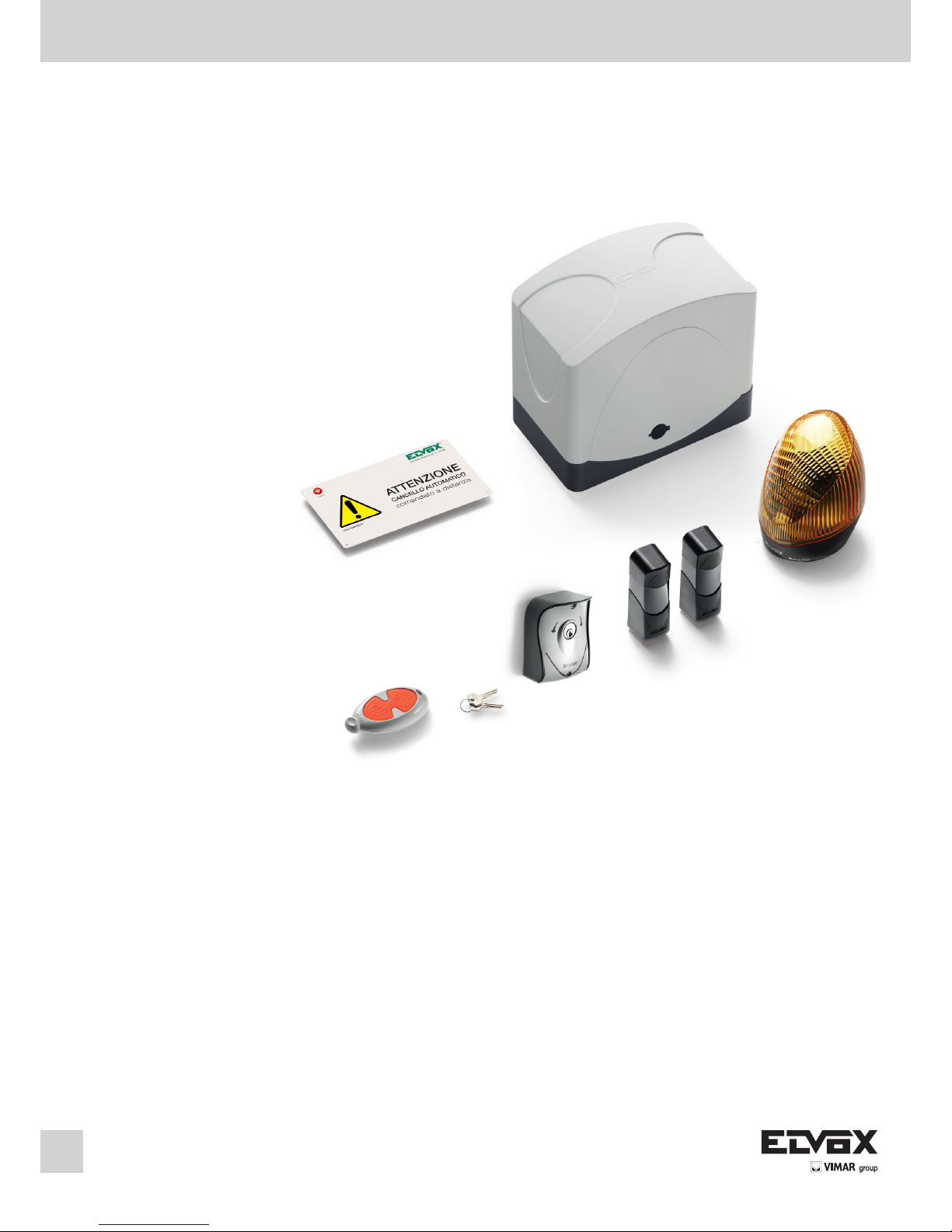
Art. ESK4
Automazione cancello scorrevole peso max 400 Kg con radiocomando a 433 MHz
Sliding gates automatic system weight 400 Kg and radio control with 433 MHz operating frequency
Actionneurs pour grilles à portes coulissantes Poids 400 Kg set radiocommande avec fréquence de
travail de 433 MHz
Manuale per il collegamento e l’uso
Installation and operation manual
Manuel pour le raccordement et l’emploi
Page 2

2
Le seguenti informazioni di sicurezza sono
parti integranti ed essenziali del prodotto
e devono essere consegnate all'utilizzatore. Leggerle attentamente in quanto forniscono importanti
indicazioni riguardanti l'installazione, l'uso e la
manutenzione. E' necessario conservare il presente
modulo e trasmetterlo ad eventuali subentranti nell'uso dell'impianto. L'errata installazione o l'utilizzo
improprio del prodotto può essere fonte di grave
pericolo.
IMPORTANTE - INFORMAZIONI DI SICUREZZA
· L'installazione deve essere eseguita da person-
ale professionalmente competente e in osservanza della legislazione nazionale ed europea
vigente.
· Dopo aver tolto l'imballo assicurarsi dell'in-
tegrità dell'apparecchio, in caso di dubbio rivolgersi a personale qualificato.
· I materiali d'imballaggio (cartone, sacchetti di
plastica, graffe, polistirolo ecc.) devono essere
smaltiti negli appositi contenitori e non devono
essere dispersi nell'ambiente soprattutto non
devono essere lasciati alla portata dei bambini.
· La posa in opera, i collegamenti elettrici e le re-
golazioni devono essere effettuati a "Regola
d'arte", assicurarsi che i dati di targa siano
rispondenti a quelli della rete elettrica e accertare che la sezione dei cavi di collegamento
sia idonea ai carichi applicati, in caso di dubbio
rivolgersi a personale qualificato..
· Non installare il prodotto in ambienti a pericolo
di esplosione o disturbati da campi elettromagnetici. La presenza di gas o fumi infiammabili
costituisce un grave pericolo per la sicurezza.
· Prevedere sulla rete di alimentazione una pro-
tezione per extratensioni, un interruttore/sezionatore e/o differenziale adeguati al
prodotto e in conformità alle normative vigenti.
· Indicare chiaramente sul cancello, porta, ser-
randa o barriera che sono comandati a distanza
mediante apposito cartello.
· La ELVOX s.p.a. non può essere considerata re-
sponsabile per eventuali danni causati qualora
vengano installati dei dispositivi e/o componenti
incompatibili ai fini dell'integrità del prodotto,
della sicurezza e del funzionamento.
· L'apparecchio dovrà essere destinato al solo
uso per il quale è stato concepito, ogni altra applicazione è da considerarsi impropria e quindi
pericolosa.
· Prima d'effettuare una qualsiasi operazione di
pulizia o di manutenzione, disinserire
l'apparecchio dalla rete, staccando la spina, o
spegnendo l'interruttore dell'impianto. Per la riparazione o sostituzione delle parti danneggiate, dovranno essere utilizzati esclusivamente
ricambi originali.
· L'installatore deve fornire tutte le informazioni
relative al funzionamento, alla manutenzione e
dell'utilizzo delle singole parti componenti e del
sistema nella sua globalità.
DICHIARAZIONE DI INCORPORAZIONE DI
QUASI-MACCHINE (DIRETTIVA 2006/42/CE)
ELVOX S.p.A.
Indirizzo: Via Pontarola 14/A – 35011 Campodar-
sego (Pd)
Dichiara che: L’articolo ESK4
è costruito per essere incorporato in una macchina
o per essere assemblato con altri macchinari per
costruire una macchina ai sensi della Direttiva
2006/42/CE è conforme ai requisiti essenziali di sicurezza delle seguenti altre direttive CEE
2006/95/CE Direttiva Bassa Tensione
2004/108/CE Direttiva Compatibilità Elettromagnetica
Inoltre dichiara che non è consentito mettere in
servizio il macchinario fino a che la macchina in cui
sarà incorporato o di cui diverrà componente non
sia stata identificata e ne sia stata dichiarata la
conformità alle condizioni della Direttiva 2006/42/
CEE e successive modifiche.
Campodarsego, 23/06/2010
L’Amministratore Delegato
The following security information is inte-
grant and essential part of the product and
must be given to the user. Read it carefully as it
gives important suggestions concerning the installation, the use and the maintenance. Keep the present manual in order to be able to transmit it to
possible future users of the installation. The erroneous installation or an improper use of the product may cause great danger.
IMPORTANT - SECURITY INFORMATION
. The installation must be carried out by profes-
sional technicians and according to the national and european safety regulations in force.
. After removing the packing check the integrity
of the appliance. If in doubt contact qualified
personnel.
. The packaging (carton, plastic bags, clips, po-
lystirene etc.) must be disposed of properly in
the appropriate containers. It must not be left
within the reach of children.
. The installation, the electrical connections and
the adjustments must be carried out perfectly;
check that the data on the specification plate
correspond to those of the mains supply and
that the connection cable cross-section is suitable for the applied loads, in case of doubt contact qualified personnel.
. Do not install the appliance in premises with
danger of explosion or disturbed by magnetic
fields. The presence of gasses or inflammable
fumes is a great danger for the safety.
. A proper protection against extratensions
should be install on the supply voltage network,
i.e. a switch/sectioner and/or differential suitable for the product and according to the regulations in force.
. The gate, door, rolling shutter or barrier should
bear a plate indicating that they are remotly
controlled.
. ELVOX S.p.A. will not accept liability for any da-
mage caused by the incorrect installation of devices and/or components not suitable for the
integrity, the safety and the operation of the unit.
. The product must only be used for the purposes
for which it was designed. Any other use is incorrect and hence dangerous.
. Before carrying out any cleaning or mainte-
nance work, disconnect the unit from the mains
supply, either by unplugging the power cord or
by switching off the mains supply.
. Any repair work or replacement of damaged
parts must be carried out by qualified personnel
using original parts and components.
. The installer must supply all the information
concerning the operation, the maintenance and
the use of the single components and the whole
system.
DECLARATION OF INCORPORATION OF PAR-
TLY COMPLETED MACHINERY
(DIRECTIVE 2006/42/EC)
ELVOX S.p.A.
Address: Via Pontarola 14/A – 35011 Campodar-
sego (Pd)
Declares that: The article ESK4
is constructed to be incorporated in a machine or
to be assembled with other machinery to construct
a machine under the provisions of Directive
2006/42/EC
conforms to the essential safety requirements of
the other following EEC directives
2006/95/EC Low Voltage Directive
2004/108/EC Electromagnetic Compatibility Directive
Furthermore it declares that the machinery covered by this Declaration must not be put into service until the machine into which it is to be
incorporated or of which it is a component has
been found and declared to be in conformity with
the provisions of Directive 2006/42/EEC and subsequent amendments.
Campodarsego, 23/06/2010
The Managing Director
Les suivants renseignements concernant
la sécurité sont partie intégrantes et es-
sentielles du produit et doivent être rémis
à l'usager. Les lire attentivement car il fournissent
importantes indications concernant l'installation. Il
est necessaire de conserver le présent manuel et
de le transmettre aux autres possibles futurs usagers. L'installation erronée ou l'emploi impropre du
produit peut être source de grave danger.
IMPORTANT - RENSEIGNEMENTS POUR LA
SÉCURITÉ
. L'installation doit être effectuée par personnel
professionnelement compétent et conforme à la
legislation nationale et européenne en vigueur.
. Après avoir enlévé l'emballage s'assurer de
l'integrité de l'appareil , en cas de doute
s'adresser à personnel qualifié.
. Les éléments de l'emballage (boîtes, sachets de
plastique, agrafes, polistirène etc.) doivent être
recyclés ou éliminés en utilisant les poubelles
prévues à cet effet pour ramassage différencié,
surtout ils ne doivent pas être laissés à la portée
des enfants.
. La mise en ouvre, les raccordements électriques
et les réglages doivent êtres effectués parfectement; les données de la plaque doivent être conformes à celles du réseau électrique et s'assurer
que la section des câbles de raccordement soit
adaptée aux charges appliqués; en cas de doute
s'adresser à personnel qualifié.
. Ne pas installer le produit dans des environne-
ments avec danger d'explosion ou dérangés par
des champs électromagnetiques . La présence
de gas ou fumées inflammables constitue un
grave danger pour la sécurité.
. Prévoir sur le réseau d'alimentation une protec-
tion contre les extratensions: un interrupteur/sectionneur et/ou différentiel appropriés au
produit et en conformité aux normes en vigueur.
. Indiquer clairement sur la grille, porte, rideau rou-
lant et barriére (au moyen d'une plaque appropriée) qu'ils sont gérés à distance.
. ELVOX S.p.A. décline toute responsabilité pour
des dommages éventuels à cause d'une installation des dispositifs et/ou composants incompatibles aux buts de l'intégrité du produit, de la
sécurité et du fonctionnement.
. L'appareil devra être destiné qu'à l'usage pour
lequel il a été conçu, toute autre application doit
être considérée comme impropre et donc dangereuse.
. Avant d'effectuer une opération de nettoyage ou
d'entretien quelconque, débrancher l'appareil en
enlevant la fiche ou en déclenchent l'interrupteur
de l'installation.
Pour la réparation ou remplacement des parties
endommagées, il faut utiliser seulement pièces
détachées et composants d'origine.
. L'installateur doit fournir tous les renseignements
relatifs au fonctionnement, à l'entretien et à
l'emploi des composants individuels et du système dans sa globalité.
DÉCLARATION D'INCORPORATION DE
QUASI-MACHINES (DIRECTIVE 2006/42/CE)
La société ELVOX S.p.A.
Adresse : Via Pontarola 14/A – 35011 Campodarsego (Pd)
Déclare que : L’article ESK4
a été fabriqué pour être incorporé dans une machine
ou pour être assemblé à d'autres équipements en vue
de réaliser une machine conforme à la Directive
2006/42/CE
est conforme aux dispositions de sécurité des directives CEE suivantes :
2006/95/CE Directive Basse Tension
2004/108/CE Directive Compatibilité Électromagnétique
En outre, elle déclare qu'il est interdit de mettre la machine en service tant que la machine dans laquelle elle
sera incorporée ou de laquelle elle deviendra un composant, n'aura été identifiée et n'aura été déclarée
conforme aux dispositions de la Directive 2006/42/
CEE et modifications suivantes.
Campodarsego,
23/06/2010
L'Administrateur Délégué
I
GB F
Page 3

3
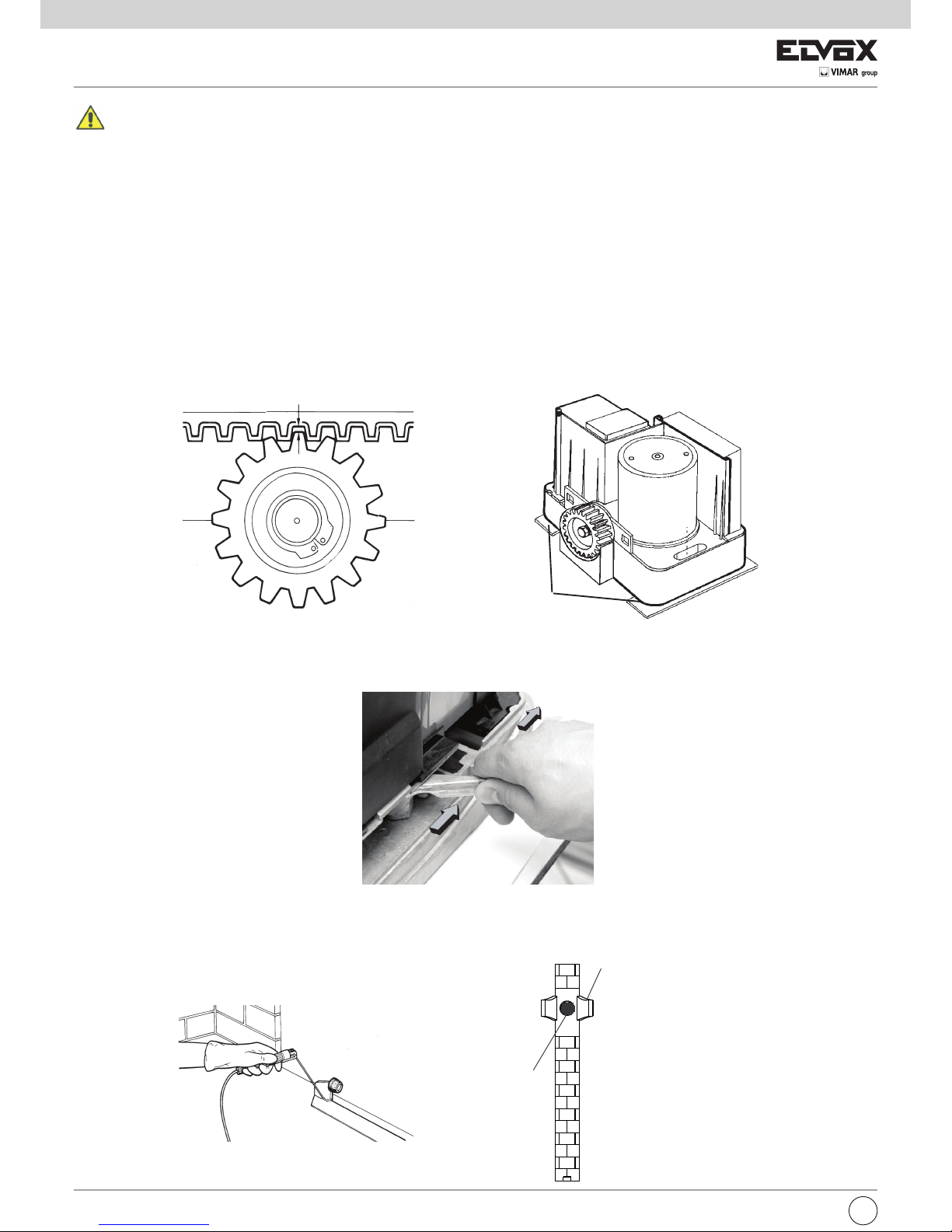
I versi di marcia dell’attuatore (M1) e quindi l’esatta polarità dei cavi (morsetti 1-2), si determinano durante la
memorizzazione della corsa.
The running directions of the actuator (M1), and therefore the exact polarity of the cables (terminals 1-2), are
determined during stroke saving.
Les sens de marche de l'actionneur (M1) et donc la polarité exacte des câbles (bornes 1-2) sont déterminés
durant la mémorisation de la course.
M1
+
-
4A
12Va.c.
Motore 1
Motor 1
Moteur 1
Aux 12V 1W
Lampeggiante
12V 5W
Flashing light
12V 5W
Clignotant
12V 5W
Antenna
Aerial
Antenne
Batteria opzionale
Battery optional
Alimentation réseau
12V 7Ah
Trasformatore
Transformer
Transformeteur
230V-12V 150VA
Scheda carica batteria
(ECB1) opzionale
Battery charge card
(ECB1) optional
Carte charge batterie
(ECB1) option
Alimentazione rete
Mains power supply
Alimentation réseau
Trimmer
Programmazione
Settings
Programmation
Pulsante Apri/Chiudi
Open/Close button
Bouton Ouvrir/Fermer
Ricevitore radio
Radio receiver
Récepteur radio
433 MHz
Fusibile - Fuse - Fusible
4A (T41)
Comune - Common - Commun
Contatto N.A. Apre/chiude - N.O. contact Open/close - Contact N.O. Ouvrir/Fermer
Contatto N.A. Apre pedonale - N.O. contact Pedestrian open
Contact N.O. Ouvrir passage piéton
Comune - Common - Commun
Contatto N.C. STOP - N.C contact STOP - Contact N.F. STOP
Contatto N.C. fotocellule - N.C. contact photocells - Contact N.F. photocellules
Contatto N.C. fotocellule in apertura - N.O. contact opening photocells
Contact N.O. photocellules en ouverture
Encoder maqgnetico
Magnetic encoder
Codeur magnétique
Alimentazione delle fotocellule
Photocells supply voltage
Alimentation de cellules photoélectrique
2° canale
Channel 2
2 éme canal
12V 1W
(+)
(-)
Page 4

4
I
CARATTERISTICHE GENERALI
Automazione, serie ES, per cancelli scorrevoli residenziali e condominiali ad uso intensivo. L’attuatore elettromeccanico irreversibile è dotato di un motore in bassa tensione, 12 Vcc, e uno sblocco meccanico che permette di aprire e chiudere il cancello manualmente. Il motore aziona un gruppo riduttorre,
lubrificato con grasso permanente, racchiuso in una fusione d’alluminio di grosso spessore ma di ridottissimo ingombro. La scheda elettronica di comando è integrata al corpo dell’attuatore. Gli attuatori sono predisposti per l’allogiamento della batteria tampone art. ZBA1 (opzionale).
308
270
188
37
DIMENSIONI D' INGOMBRO
CONTENUTO DELL’IMBALLO
N°1 -Attuatore con scheda e ricevitore
N°1 -Lampeggiante
N°1 -Radiocomando 2 canali 433 MHz
N°1 -Coppia di fotocellule da esterno parete
N°1 -Selettore a chiave
N°1 -Cartello “Attenzione”
N°1 -Tappo per fermo battuta cancello
N°2 -Spessori per montaggio cremagliera
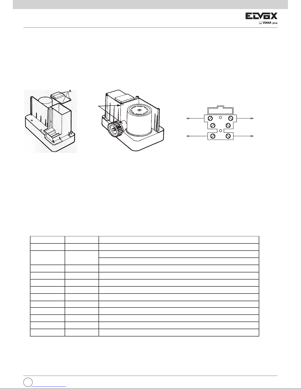
INSTALLAZIONE TIPO
A = piastra opzionale (330x208 mm)
B = cremagliera art. ZE03 - ZE07 - ZE08
C = cancello scorrevole
D = ruota
E = livello terreno
ES04 ES04/117 ES04/240
230 Vac (+6%, -10%) 117 Vac (+6%, -10%) 240 Vac (+6%, -10%)
50-60 Hz
13÷15 Vc.a..
12 Vc.c.
Servizio intensivo
25 Watt
1300 RPM
Modulo 4
-25°C ÷ 55°C
IP45
400 Kg
308x270x225 mm.
Alimentazione Rete
Frequenza
Alimentazione scheda
Alimentazione motore
Intermittenza lavoro
Potenza Max. Motore
Velocità Max Motore
Pignone cremagliera
Temperatura di servizio
Grado di protezione
Peso Max. anta Cancello
Dimensioni (LxHxP)
CARATTERISTICHE TECNICHE DI TARGA
ATTUATORE
A
B
C
D
E
40
Fig. 1
62mm (ZE03-ZE08)
98mm (ZE07)
Automazione
serie ES...
*
*
Page 5

I
5
Fig. 2A
Fig. 2B
Fig. 2C
B
A
C
D
D
Fig. 3A
Fig. 3B
INSTALLAZIONE MECCANICA
Per un corretto funzionamento dell’automazione la struttura del cancello esistente, o da realizzare, deve presentare i seguenti requisiti:
- Le ruote del cancello siano montate in posizione tale da dare stabilità al cancello stesso e che siano in buono stato ed efficienti.
- La rotaia sia libera diritta e pulita in tutta la sua lunghezza con battute d’arresto obbligatorie sia in apertura che in chiusura.
- La guida superiore sia in asse con la rotaia, i pattini siano integri e lubrificati e con un gioco di circa 1 mm. per parte in modo da facilitare lo scorrimento dell’anta.
- Gli spazi tra le parti mobili e le parti fisse del cancello siano di entità prevista dalle norme nazionali o comunque siano ricondotti ai canoni di sicurezza
applicando un adeguato sistema di protezione.
- Il peso del cancello non deve superare i 600 Kg
- Assenza di serrature meccaniche di chiusura.
Si raccomanda di effettuare gli interventi necessari per garantire l’affidabilità e la sicurezza dell’automazione
Installazione dell’attuatore
1. Togliere il tappo della serratura (Fig. 2A) ed inserire la chiave (Fig. 2B). Togliere il blocco della serratura.
2. Togliere il coperchio di plastica premendo leggermente nei due lati (Fig. 2C).
3. Per il fissaggio al suolo del motoriduttore utilizzare la contropiastra, Art. ZX16 (non in dotazione)
Preparazione del sito
Individuato il luogo dove installare il motoriduttore (che può essere alla destra o alla sinistra del cancello), è possibile fissare il motore con due tasselli oppure utilizzare la contropiastra in due modi:
1) Muratura della piastra (Fig. 3A- Fig. 3B)
2) Fissaggio nel suolo tramite 4 tasselli (non in dotazione)
N.B. La contropiastra deve essere murata o fissata seguendo scrupolosamente le misure indicate in fig. 1 per garantire il corretto ingranamento tra il pignone del motoriduttore e la cremagliera.
Muratura della piastra
a. Piegare le 3 zanche Fig. 3A
b. Posizionare la contropiastra in modo che la zanca centrale sia verso il pignone del motoriduttore (quindi verso la cremagliera) Fig. 3B particolare A.
c. Inserire le due viti, M8x30, in dotazione nei fori quadrati della piastra e fissarle tramite i dadi in modo da incastrarle nel quadro, Fig. 3B particolare C.
d. Utilizzare dei tubi flessibili, necessari per il passaggio dei cavi di collegamento (accessori - alimentazione elettrica).
Passare i tubi flessibili tra i fori, Fig. 3B particolare B. I tubi devono uscire circa 5 cm dai fori della piastra.
e. Murare perfettamente in piano la contropiastra.
Fissaggio con tasselli
Preparare una piazzola piana di tenace calcestruzzo di area sufficiente a coprire la contropiastra.
N.B. Si consiglia di realizzare una piazzola che sporga di qualche centimetro dal livello del suolo per evitare che il motoriduttore sia interessato dal ristagno
o dal deflusso di acqua piovana.
- Seguire il punto c e d.
- Fissare la contropiastra con 4 tasselli da fondazione, M8x120mm Fig. 3B particolare D non in dotazione, e stringere le viti utilizzando le rondelle (itasselli
permettono la regolazione della piastra in altezza).
Fissaggio del motoriduttore
- Predisporre i cavi
- Posizionare il motoriduttore rispettando le misure indicate nella fig. 1. Appoggiare il motoriduttore sulla contropiastra in modo che le viti, M8x30, entrino
nei due fori di fissaggio della fusione e fissare i dadi preceduti da una rondella piana ed una dentata, vedi Fig. 3C particolare E.
Fig. 3C
E
Page 6
6
I
Fig. 4B
Fig. 4A
2 mm ottenuti al termine della regolazione
Spessori
SBLOCCO MANUALE
In caso di mancata alimentazione di rete, la batteria tampone (opzionale) garantisce per un periodo limitato il funzionamento dell’automazione. Se la batteria è scarica o non utilizzata sbloccare manualmente il motore aprendo il coperchio con l’apposita chiave (vedi Fig.
1A, Fig. 1B, Fig. 1C) e ruotare la leva dello sbocco di 180° in senso antiorario (Fig. 5). Richiudere il coperchio.
Fig. 5
INSTALLAZIONE BATTENTI MECCANICI
In corrispondenza delle posizioni di aper tu ra e chiusura del cancello scor re vo le bisogna sistemare dei battenti mec ca ni ci che siano in grado
di ar re sta re il mo vi men to del cancello sia in aper tu ra (Fig. 6A) che in chiusura (Fig. 6B). Se gui re co mun que i consigli delle varie nor me e
direttive a riguardo.
Fig. 6A
TAPPO
FORCELLA
VISTA FRONTALE FERMO
BATTUTA CANCELLO
Installazione della cremagliera:
1 -Chiudere completamente il cancello.
2 -Si deve garantire un gioco di 2mm. tra pignone e cremagliera su tutta la lunghezza del cancello (Fig. 4A). Per fare ciò posizionare
gli spessori (in dotazione) come mostra la Fig. 4B e fissare il motoriduttore.
N.B. Questa operazione è molto importante per il funzionamento e la durata del motoriduttore. Infatti è opportuno che il carico del cancello non gravi sul pignoneperchè potrebbe danneggiare l’automazione.
3. Sbloccare il motoriduttore tirando verso destra la leva di sblocco meccanico (Fig. 5).
4. Appoggiare la cremagliera sul pignone in modo che, una volta fissata, la sua estremità coincida con la fine dell’anta del cancello. Segnalare laposizione dei fori.
5. Far scorrere il cancello in tutta le sua lunghezza ripetendo il procedimento per trovare i punti di fissaggio o di saldatura.
6. Per l’utilizzo della cremagliera in nylon, forare il cancello con punta da 5,25 mm, e fissare la cremaglira con viti autofilettanti da 6,3 mm
(fornite con lacremagliera). Per l’utilizzo della cremagliera in acciaio zincato, saldare gli attacchi e fissare la cremagliera con le viti, M8,
(fornite con la cremagliera) pre-cedute dalla rondella.
7. Fissata la cremagliera allentare le viti che fissano l’attuatore e togliere gli spessori.
8. Riposizionare il gruppo del motoriduttore in modo che il pignone sia sormontato esattamente dalla cremagliera. Il risultato dovrà corrispondere esattamentecon quello di Fig. 4A.
Page 7
I
7
Fig. 7C
Fig. 7B
Fig. 7A
Fusibile 2AL250V (Rete: 230V, 240V)
Fusibile 4AL250V (Rete: 110V, 117V, 125V)
Rete
Trasformatore
A
Ciascun dispositivo deve essere installato a regola d’arte, seguendo le istruzioni allegate e soprattutto fare eseguire la messa in opera da personale qualificato Elvox rispettando la normativa vigente in ciascun paese. Seguire le istruzioni allegate per il collegamento dei cavi della scheda
elettronica di comando; si ricorda che:
1 -
La centralina di comando viene alimentata da un trasformatore di sicurezza.Per collegare l’alimentazione all’automazione svitare le 4 viti e
togliere il coperchio (Fig. 7A), entrare con il cavo RETE 230Vc.a. come da punto A, Fig.7B e collegarlo nella morsettiera come nella Fig. 7C.
2 -La sezione consigliata dei cavi di rete per il collegamento dell'automazione è di 1,5 mm2.
3 -L’impianto di messa a terra del cancello deve essere conforme alle norme vigenti. La casa costruttrice declina ogni responsabilità per danni
derivanti da eventuali negligenze in materia.
4 -In accordo con la normativa europea in materia di sicurezza si consiglia di inserire un interruttore bipolare esterno per poter togliere
l’alimentazionein caso di manutenzione del cancello e di scollegare il morsetto delle alimentazioni della scheda.
INSTALLAZIONE ELETTRICA
N° Morsetti Descrizione Funzione
1 2 Motore 1 Alimentazione motore 1 12Vc.c.
3 4 2° Canale Uscita secondo canale selezionabile tramite parametro.
Tensione temporizzata 12Vc.c. 1W o funzione pedonale.
4 5 AUX Uscita con tensione 12V c.c. 1W IN o funzione spia di segnalazione.
6 7 (-)12 (+)12 Alimentazione fotocellule 12V DC 500 mA max.
8 9 LAMP Lampeggiante 12Vc.c. 5W max.
10 11 COM - AP/CH Ingresso selettore o pulsante, contatto NA, APRE/CHIUDE.
10 12 COM - PED Ingresso selettore o pulsante, contatto NA, apertura pedonale
19 14 COM - STOP Ingresso selettore o pulsante funzione STOP, contatto NC.
13 15 COM - FOT Ingresso fotocellule, contatto NC.
13 16 COM - STPA Ingresso fotocelle in apertura (interna) o bordo sensibile, contatto NC.
(-) ANT Antenna Collegamento cavetto o cavo antenna
CN4 Encoder Encoder magnetico
SCHEDA ELETTRONICA EC10
La scheda elettronica, Art. EC10, è adatta per il comando di un attuatore per cancelli scorrevoli, serie ES, con motore in corrente continua a 12 Volt.Si tratta di una scheda con elevati standard qualitativi, dotata di un sistema di controllo del movimento del cancello tramite
un ENCODER per garantirela conformità alle prescrizioni delle direttive sulla compatibilità elettromagnetica, la marcatura CE e le normative vigenti per la sicurezza. Il raggiungimentodell’apertura/chiusura del cancello avviene attraverso rallentamento dell’anta, nel suo movimento viene costantamente monitorata la velocità ed il consumo amperometrico del motore, ed in caso di ostacolo avviene l’inversione
del moto.
INSTALLAZIONE ELETTRICA
La centralina di comando della scheda EC10 è alimentata a 230V (a 117V per la versione /117 e a 240V per la versione /240V), la tensione
di rete è protetta con un fusibile da 4A. La scheda si alimenta con 12Vac tramite un trasformatore di sicurezza in doppio isolamento
(EN61558).Gli attuatori ed i comandi sono alimentati a 12Vcc e le uscite sono protette da due fusibili: F1 da 15A per gli attuatori e F2 da
3,15A per gli accessori. Temperatura di funzionamento -20 ÷ +55°C.
Essendo la scheda in bassa tensione le strutture metalliche ad essa connesse non devono essere collegate a terra in quando si tratta di
alimentazione SELV. Per cablaggi con lunghezza superiore a 15 metri usare conduttori di sezione 2x4 mm².
Page 8

8
I
La scheda EC10 prevede due modalità di funzionamento, a seconda del tipo di automazione che si desidera controllare. Tale modalità è
stabilita dalla posizione del dipswitch 8:
1. scorrevole (dipswitch 8 off)
2. barriera (dipswitch 8 on)
La modalità viene valutata all'avvio dell'apparecchiatura e, se è stata cambiata rispetto all'ultima accensione, tutti i parametri vengono riportati a default. Per questo motivo, in caso di cambiamento di modalità, è necessario ripetere l'apprendimento delle corse. I codici dei
radiocomandi eventualmente appresi invece vengono mantenuti.
N.B:
La configurazione dei dip 1-2 in posizione OFF determina la modalità di funzionamento motore scorrevole.
Attivando l’ingresso “APERTURA PEDONALE” o premendo il tasto 2° canale (se configurato), si apre l’anta, di una percentuale pari al valore impostato nel parametro “Apertura parziale”. Ripremendo lo stesso tasto, si chiude l’anta. Se invece si preme APRE/CHIUDE, viene
completata l’apertura dell’anta. Con l’anta aperta premendo APED si può ottenere la chiusura dell’anta.
SICUREZZE
Esistono tre sicurezze:
- il tasto STOP
- la fotocellula esterna
- la fotocellula interna (vanno collegati all'ingresso STPA
Il tasto STOP
Se premuto, provoca l'immediato arresto di qualunque movimento. E' necessario premere il tasto APRE/CHIUDE per far ripartire il movimento.
La fotocellula esterna
Se viene impegnata la fotocellula esterna durante la chiusura, il movimento viene arrestato e parte una riapertura completa. Se è configurata la “Richiusura automatica”, trascorso il timeout configurato, parte la chiusura. Durante un'apertura invece l'impegno della fotocellula
esterna non ha effetto.
NOTA: il disimpegno della fotocellula può avvenire anche durante l'apertura. Il movimento proseguirà fino all'apertura completa e quindi
partirà la chiusura immediata.
La fotocellula interna
Per avere questo tipo di funzionamento è necessario impostare l'ingresso STPA come “fotocellula interna” (dipswitch 4 off). Se viene impegnata la fotocellula interna durante un'apertura o una chiusura si ottiene l'arresto immediato del movimento, fino al disimpegno della fotocellula interna. Una volta liberata la fotocellula, il movimento prosegue, cioè continua ad aprirsi o a chiudersi.
MODALITA' UOMO PRESENTE
Se una delle sicurezze è attiva a causa, per esempio, di un guasto, è possibile forzare il movimento dell'automazione. Per attivare questa
modalità è quindi necessario tenere premuto il tasto APRE/CHIUDE per un tempo minimo di tre secondi. Fintantoché il tasto rimane premuto, l'automazione continua a muoversi, a meno che non arrivi in battuta chiuso o non si arrivi all'apertura completa.
DIAGNOSI DEL CABLAGGIO DELL’ IMPIANTO
La centralina è gestita da un microprocessore ed è dotata di diagnosi visiva tramite Led per controllare lo stato degli ingressi e delle uscite.
1. Controllare tutti i collegamenti prima di alimentare la scheda.
2. Gli ingressi NC non utilizzati devono essere ponticellati.
3. Alimentata la scheda verificare che i led verdi posizionati sopra alla morsettiera, nella parte inferiore destra della scheda, che indicano
gli ingressi NC
siano accessi.
4. Verificare che i led rossi posizionati sopra alla morsettiera, nella parte inferiore destra della scheda, che indicano gli ingressi NA siano
spenti.
Dopo aver alimentato la scheda:
1. i due LED (rosso e verde) vengono accesi contemporaneamente per un secondo e quindi spenti
2. se l'alimentazione proviene dalla rete AC viene acceso anche il LED “RETE ON”
3. viene mostrata la versione firmware secondo la seguente codifica:
• il numero di lampeggi del LED rosso dà la prima cifra
• il numero di lampeggi del LED verde dà la seconda cifra
Esempio: versione firmware 2.04 ci saranno 2 lampeggi del LED rosso e 4
lampeggi del LED verde
4. verifica della memoria EEPROM: se il contenuto della memoria è coerente si passa direttamente al funzionamento normale, altrimenti
essa viene cancellata completamente e riportata ai valori di default.
5. A questo punto l’apparecchiatura è pronta per funzionare.
I due fusibili presenti sulla scheda sono:
- F1 da 15 A
- F2 da 3,15 A
Page 9
I
9
FUNZIONAMENTO APPARECCHIATURA
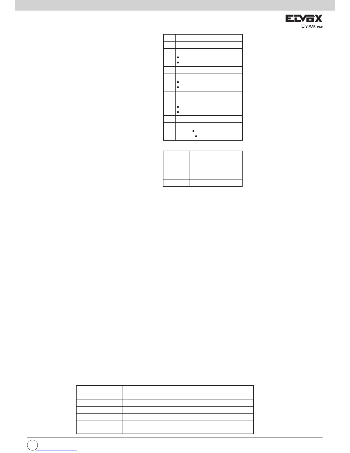
I dipswitch controllano i seguenti parametri:
I trimmer regolano i seguenti parametri:
DIP SCORREVOLE
1 Richiusura automatica on/off
2 Modalità apertura:
off = condominiale
on = apre/stop/chiude
3 Prelampeggio on/off
4 Ingresso STPA:
off = fotocellula interna
on = bordo normale
5 Verifica fotocellule on/off
6 Pedonale/2CAN:
off = pedonale
on = 2CAN
7 Non usato
8 Modalità di funzionamento:
off = scorrevole
on = barriera
TRIMMER SCORREVOLE
1 (SENSE) Sensibilità all’ostacolo
2 (V.RALL) Velocità in rallentamento
3 (V.MAX) Velocità massima
4 (AUX1) Non usato
Premendo il tasto APRE/CHIUDE viene attivato il motore in apertura. Se l'automazione è già aperta, un'ulteriore pressione del tasto ne provoca la chiusura. Se è stato programmato almeno un radiocomando, alla pressione di uno dei tasti, viene acceso brevemente il LED verde,
per segnalarne la corretta ricezione.
Premendo il tasto AP PEDONALE l'apertura si arresta in un punto pari a 30% della corsa totale.
Ripremendo lo stesso tasto, parte la chiusura. Se invece si preme APRE/CHIUDE, viene completata l'apertura.
Premendo APRE/CHIUDE durante l'apertura pedonale, il movimento prosegue fino all'apertura completa.
RICHIUSURA AUTOMATICA
Questa funzione è controllata dal dipswitch 1. Se attiva, l'automazione si richiude automaticamente dopo un tempo pari:
• a 30 secondi, se è stato usato l'apprendimento facilitato
• a quello acquisito durante l'apprendimento completo
MODALITA' APERTURA
La modalità apertura è controllata dal dipswitch 2. Le logiche impostabili sono:
• CONDOMINIALE: l'automazione in apertura non reagisce ad altri comandi, cioè continua ad aprire. In chiusura invece, un comando provoca la riapertura
• APRE – STOP – CHIUDE: in movimento, una pressione del tasto APRE/CHIUDE fa arrestare il movimento
IL LAMPEGGIANTE
Il lampeggiante si accende a intermittenza durante i movimenti di apertura e di chiusura. Rimane invece spento a cancello chiuso e nel caso
in cui si fermi in maniera permanente. Se sono configurati i parametri “richiusura automatica” e/o “richiusura immediata”, il lampeggiante
rimane acceso, indicando che entro breve si attiverà un movimento automatico, ad esempio di richiusura. Se invece lampeggia rapidamente, è un indicazione di un possibile guasto alle fotocellule.
L'USCITA AUX
L'uscita AUX viene attivata nel momento in cui viene ricevuta una richiesta di apertura e rimane attiva fintantoché il cancello non viene
chiuso.
SEGNALAZIONI DI ERRORE
Le seguenti segnalazioni tramite lampeggiante permettono di capire se si è verificato un errore. L'automazione, se era in movimento, si arresta e viene emesso un certo numero di lampeggi secondo la codifica indicata nella seguente tabella:
NUMERO LAMPEGGI SIGNIFICATO
2 Fallito il test delle fotocellule
3 Rilevato un problema nel circuito che attiva il motore
4 Problema sull’encoder
5 Errore grave sulla EEPROM
6 Esaurito il tempo previsto per il termine della corsa
7 Fusibile F2 rotto
Page 10
10
I
APPRENDIMENTO CORSA
Esistono due modalità di apprendimento della corsa:
1. apprendimento facilitato (Easy Learning)
2. apprendimeno completo (Learning)
Per attivare l'apprendimento facilitato (LEARN EASY), tenere premuto il tasto Prog. A. Dopo 2 secondi il LED rosso inizia a lampeggiare
lentamente, rilasciando il tasto il LED continuerà a lampeggiare lentamente. È sufficiente quindi premere APCH una volta e l'apprendimento
proseguirà in modo del tutto automatico. I punti di rallentamento in apertura e in chiusura vengono fissati di default rispettivamente a
70% e a 30% della corsa totale.
NOTA: in caso di apprendimento facilitato (LRNE) durante la prima apertura, non viene fatto il rallentamento.
Per attivare l'apprendimento completo, tenere premuto il tasto Prog. A. Dopo 4 secondi il LED rosso inizia a lampeggiare velocemente, rilasciando il tasto il LED continuerà a lampeggiare velocemente. Premere APCH per far partire la richiusura.
L'apprendimento proseguirà secondo i passi indicati nella seguente tabella.
PASSO SIGNIFICATO
INIZIO
APPRENDIMENTO
Attivare l’ingresso APRE/CHIUDE (anche sul radiocomando, se
configurato). Fa partire la manovra di chiusura.
CHIUSURA INIZIALE Chiusura iniziale, attendere l’arrivo in battuta chiuso
APERTURA Manovra di apertura. Attivare APRE/CHIUDE per impostare il
punto in cui deve iniziare il rallentamento in apertura.
RALLENTAMENTO
IN APERTURA
Rallentamento in apertura, attendere l’arrivo in battuta aperto o
attivare APRE/CHIUDE per fissare il punto in cui l’automazione
va considerata aperta.
APPRENDIMENTO
TEMPO SOSTA
Attendere un tempo pari al tempo di sosta desiderato per la funzione “Richiusura automatica”. Attivare APRE/CHIUDE per memorizzare il tempo.
CHIUSURA Manovra. Attivare APRE/CHIUDE per impostare il punto in cui di
deve iniziare il rallentamento in chiusura.
RALLENTAMENTO
IN CHIUSURA
Rallentamento in chiusura, attendere l’arrivo in battuta chiuso.
APPRENDIMENTO
APERTURA PEDONALE
Manovra di apertura rallentata. Attivare APRE/CHIUDE per fissare il punto in cui l’automazione va considerata aperta pedonale (apertura parziale) (solo modalità SCORREVOLE)
CHIUSURA FINALE Manovra di chiusura, attendere l’arrivo in battuta chiuso
(solo modalità SCORREVOLE)
END Procedura conclusa con successo. I parametri vengono salvati
in memoria.
NOTA: è possibile interrompere la procedura in qualsiasi momento attivando l'ingresso STOP. Il LED rosso lampeggerà velocemente per
qualche secondo e quindi si spegnerà. In questo caso non viene salvato nulla di quanto appreso.
NOTA: se all'inizio della procedura non viene attivato l'ingresso APRE/CHIUDE entro 30 secondi, si esce dalla modalità apprendimento e
viene fatto lampeggiare velocemente il LED rosso.
Page 11

I
11
PROGRAMMAZIONE RADIOCOMANDI
Tenendo premuto il tasto Prog. B è possibile attivare la modalità di programmazione e cancellazione dei radiocomandi.
NOTA: il primo radiocomando appreso imposta la tipologia di radiocomandi utilizzabili.
Le tipologie supportate sono 2: a rolling code e a codice fisso.
1. Premendo il tasto per più di 2 secondi il LED inizia a lampeggiare lentamente, rilasciando il tasto si attiva la modalità di apprendimento
del canale 1, corrispondente all'ingresso APRE/CHIUDE.
2. Premendo il tasto per più di 4 secondi il LED inizia a lampeggiare velocemente, rilasciando il tasto si attiva la modalità di apprendimento
del canale 2. A seconda del valore assunto dal dipswitch 4, questo tasto può attivare l'uscita 2CAN o attivare l'ingresso
APRE/PEDONALE
3. Premendo il tasto per più di 6 secondi il LED inizia a lampeggiare molto velocemente, rilasciando il tasto si attiva la modalità di cancel-
lazione dei radiocomandi già appresi.
Il radiocomando che trasmetto viene memorizzato o cancellato, a seconda della modalità corrente. A conferma dell'operazione il LED
verde viene acceso per un secondo.
Se il LED non si accende significa che:
• il radiocomando è di tipo diverso da quelli utilizzabili (es: ho già appreso radiocomandi a rolling code e tento di apprendere un radiocomando a codice fisso)
• sto apprendendo radiocomandi per il canale 1 e il radiocomando attivato è già memorizzato come canale 2 (e viceversa)
• sto cancellando radiocomandi e il radiocomando corrente non è tra i memorizzati
Per uscire dalla modalità attiva premere brevemente il tasto Prog. B. Si spegne il LED verde.
CANCELLAZIONE TOTALE DEI RADIOCOMANDI
Per cancellare completamente tutti i radiocomandi memorizzati è necessario spegnere l'apparecchiatura EC10 e riaccenderla tenendo
premuto il tasto Prog. B.
Al termine della fase di avvio della scheda, se il tasto è ancora premuto, viene fatto lampeggiare il LED verde molto velocemente, a conferma che la cancellazione totale dei telecomandi è andata a buon fine. A quel punto la scheda inizia a funzionare normalmente.
FUNZIONAMENTO IN BATTERIA TAMPONE
In caso di mancanza dell'alimentazione di rete, l'apparecchiatura è in grado di funzionare lo stesso, sfruttando la batteria tampone (opzionale).
Alcune funzionalità vengono eliminate o ridotte, per garantire più movimenti possibile dell’anta. In particolare:
• si spegne il LED “AC”
• il movimento dell’anta è a velocità costante, comunque più lento rispetto alla velocità normale in caso di alimentazione di rete
• se torna attiva la tensione di rete e il cancello è in movimento, l’anta subisce una leggera accelerazione, dovuta all'aumento di tensione,
quindi si ferma un attimo. Il movimento poi riprende rallentato fino a portarsi sempre nella condizione di aperto.
Ciò consente all'apparecchiatura di riallinearsi. La successiva chiusura avverrà normalmente (non rallentata).
In batteria continuano a essere attive le seguenti funzionalità:
• l'apertura pedonale
• la richiusura automatica
• il lampeggiante: viene acceso brevemente solo PRIMA dell'inizio del movimento (in apertura e in chiusura) e poi rimane spento
• in caso di ostacolo, il movimento si arresta. Non c'è arretramento, ma il movimento è lento, per cui non si determina una condizione di
pericolo
Vengono invece disattivati:
• l'uscita AUX
• l'alimentazione degli accessori (fotocellule etc) quando il cancello è fermo.
• l'uscita 2CAN
Page 12
12
I
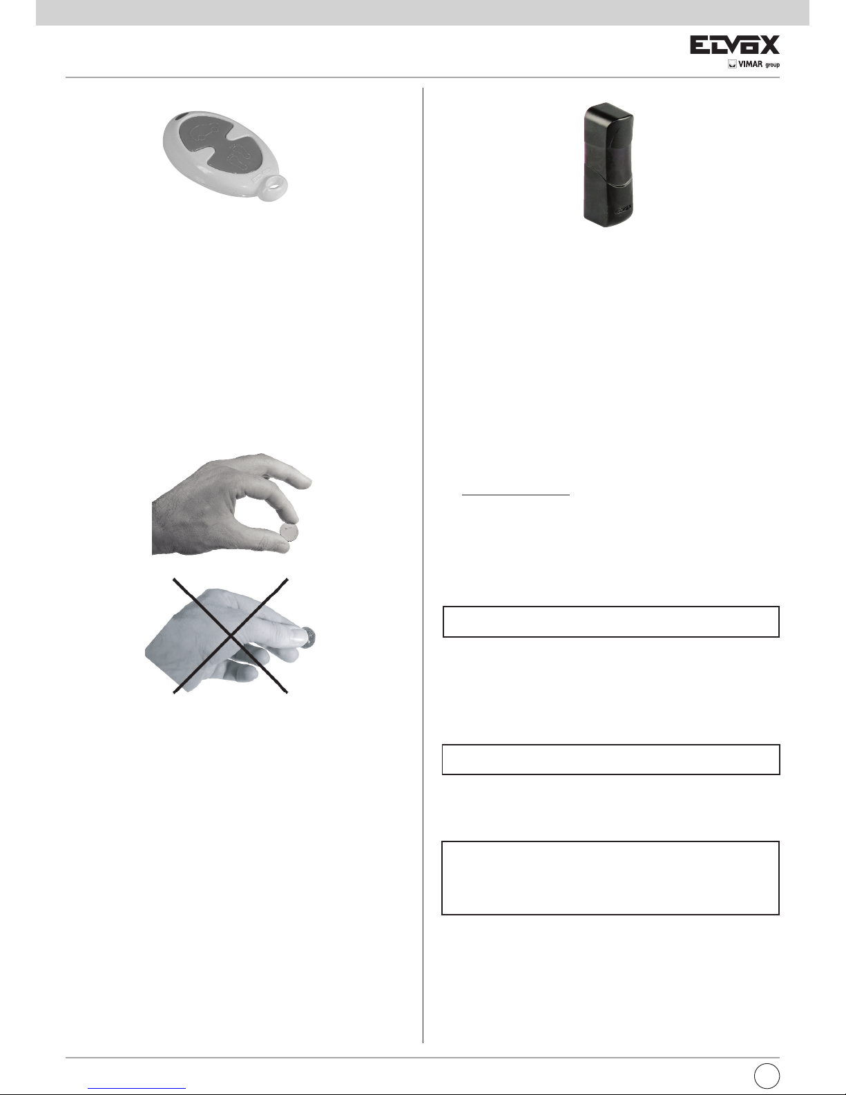
FOTOCELLULE ART. EFA1
Fotocellula vesione sincronizzata da esterno parete con possibilità di ruotare il circuito 180°. Costituita da ricevitore (RX) e da un trasmettitore (TX)
a raggi infrarossi modulati.
N.B. È vietato l’uso per riflessione a l’installazione in superfici non rigide
soggette a vibrazioni.
Caratteristiche tecniche:
- Alimentazione:
12 Vcc/ca con il ponticello, 12-24, inserito (limiti 10-18 Vc.a.)
24 Vcc/ca senza ponticello, 12-24 (limiti 18-32 Vc.a.)
- Assorbimento max.:
a 12V: Rx 46mA, Tx (min) 65 mA, Tx (sync.) 37 mA
a 24V: Rx 55mA, Tx (min) 54 mA, Tx (sync.) 45 mA
- Portata relè: 1A a 24 Vc.c. / 120 Vc.a.
- Tempo di risposta: < 30 ms.
- Temperatura di funzionamento: -20°C ¸ +55°C
- Angolo di rilevazione: Rx ± 20°C
- Angolo raggio emesso: Tx ± 12°C
- Grado di protezione: IP55
- Portata massima: 15 m
N.B. La portata si può ridurre del 50% in presenza di fenomeni atmosferici: nebbia, pioggia, polvere ecc.
Dimensioni (lxhxp): 34x113x36 mm
COLLEGAMENTI
1) Selezionare l’alimentazione della fotocellula agendo sul ponticello
JP12V di selezione della tensione. La scelta 12/24 Vcc/ca va fatta in
base alla tensione disponibile della centralina
JP 12 con ponticello inserito=Alimentazione 12Vc.c./c.a.
JP 12 senza il ponticello=Alimentazione 24Vc.c./c.a.
2) Nel caso di due trasmettitori (TX) vicini, il raggio di uno potrebbe in-
terferire sull’altro ricevitore non garantendo il corretto funzionamento.
Per ovviare questo problema, se disponibile l’alimentazione in corrente alternata, è possibile utilizzare il sistema di sincronismo che permette di far funzionare alternativamente le due coppie di fotocellule.
Per attivare la funzione di sincronismo si deve togliere il ponticello,
sync, del trasmettitore (TX).
Ponticello "sync" inserito = funzionamento normale
Ponticello "sync" non inserito = funzione sincronismo
3) Eseguire i collegamenti elettrici in base alla funzione richiesta, se-
condo quanto riportato nelle caratteristiche tecniche
Il led bicolore presente nel ricevitore consente di ottenere una verifica
dell’allineamento corretto tra RX e TX.
LED Significato
Spento Alimentazione assente
Rosso Presenza ostacolo, allineamento errato
Lampeggiante Allineamento non perfetto
Verde Allineamento ottimale
4) Eseguita l’installazione della fotocellula. Controllare il funzionamento
interrompendo più volte il fascio (raggio infrarosso); verificare
l’accensione del led rosso della ricevente e la commutazione del relè.
5) Eseguito il collaudo posizionare il frontalino.
INSTALLAZIONE:
1) Inserire un cacciavite a taglio nella fessura ricavata nel lato inferiore
dentrale del coperchio (vedi Fig. 8).
2) Fissare il fondo della fotocellula in parete, applicando dei tasselli, cer-
cando di ottenere l’allineamento migliore.
FOTOCELLULA RUOTANTE 180° DA ESTERNO PARETE
RADIOCOMANDO A 2 CANALI ROLLING CODE
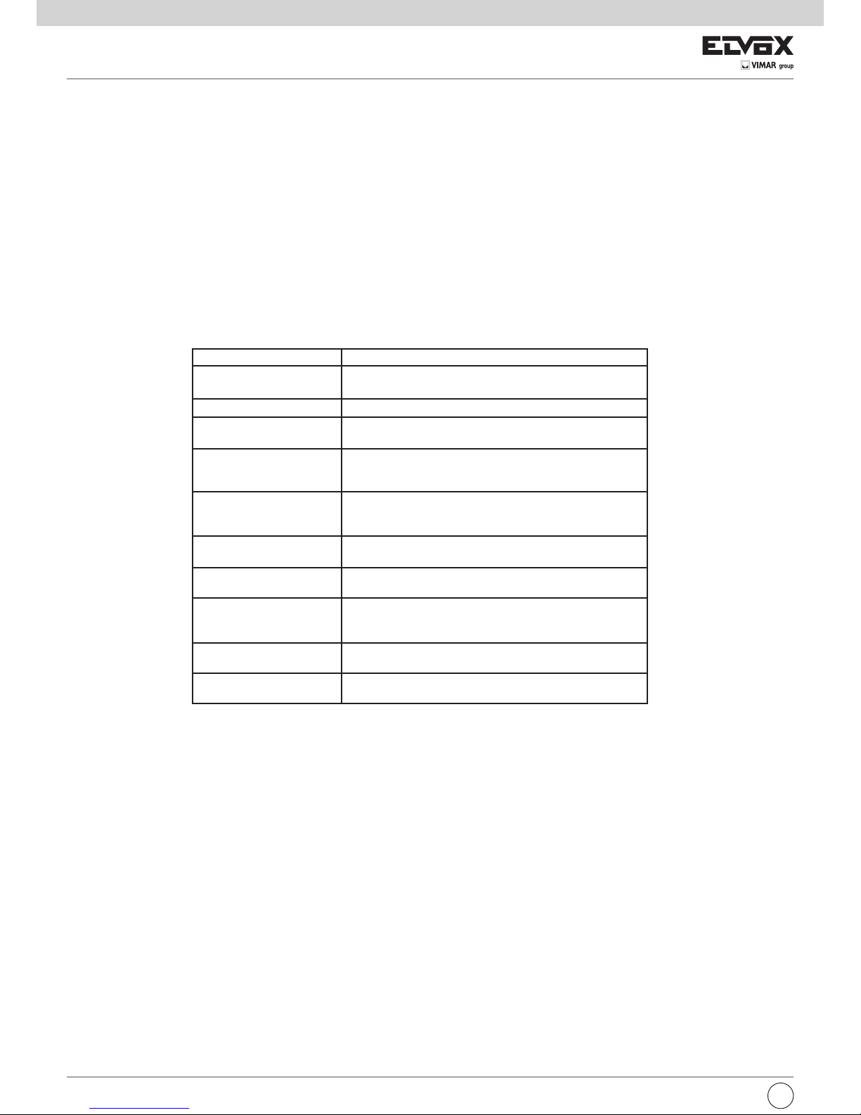
RADIOCOMANDO ART. ETR2
Per ogni radiocomando viene memorizzato di serie un codice diverso.
CARATTERISTICHE TECNICHE
Frequenza: 433,92 MHz.
Batteria: 2x3V (CR2016)
Portata: 50¸100 m
Combinazioni codice: 4.294.967.296
Dimensioni: 71x38x14 (mm)
Peso: 16gr.
SOSTITUZIONE BATTERIA
Togliere la vite di fissaggio ed aprire il coperchio. Rimuovere le batterie
e sostituirle rispettando la polarità.
Page 13

I
13
COLLEGAMENTO DI DUE COPPIE DI FOTOCELLULE
COLLEGAMENTO DI DUE COPPIE DI FOTOCELLULE CON FUNZIONE DI SINCRONISMO
COLLEGAMENTO DI 1 COPPIA DI FOTOCELLULE
COMUNE
CONTATTO N.C.
Alimentazione: 12/24Vc.c./c.a
~
~
COM
Alimentazione: 12/24Vc.c./c.a
Alimentazione: 12/24V c.a
-
+
FOT
COM
-
+
FOT
COM
Fig. 8
Fig. 9
Fig. 10
FOT
Page 14

14
I
Il radiocomando non funziona. I codici del radiocomando e quelli
memorizzati nella scheda sono diversi.
Batteria Scarica.
Eseguire la procedura di acquisizione del
codice radio (vedi istruzioni).
Sostituire la batteria
Non si programma la corsa
dell’automazione.
Dispositivi di protezione o comandi attivi.
Velocità di rallentamento bassa.
Assorbimento motore superiore al limite im-
postato in laboratorio.
Verificare che i 3 led verdi, relativi alle prote-
zioni, siano accesi e i led rossi, dei co-
mandi, spenti.
Se il cancello si blocca durante la program-
mazione bisogna aumentare la velocità di
rallentamento e la forza.
Rivolgersi all’assistenza clienti.
Misurare tramite un tester, in modalità corrente continua, l’assorbimento del motore:
deve essere minore di 5A. Se supera i 4A,
verificare la corsa del cancello ed eliminare
eventuali attriti meccanici.
In fase di programmazione l’automazione
non apre ma chiude.
Sono invertiti i cavi alimentazione motore. Invertire la polarità dei conduttori Rosso e
Nero (morsetto 1 e 2).
L’automazione si blocca quando inizia a
rallentare.
Struttura meccanica del cancello con
problemi.
Velocità di rallentamento bassa.
Verificare la struttura meccanica del can-
cello (lo scorrimento a motore sbloccato, il
buono stato della rotaia, …).
Aumentare la Velocità di rallentamento.
Il lampeggiante rimane spento anche
durante la corsa.
Funzionamento batteria
(scheda batteria opzionale).
Verificare la carica della batteria.
Il lampeggiante non funziona oppure rimane
sempre accesso.
Lampadina bruciata.
La scheda non funziona correttamente.
Sostituire la lampadina (tipo E14 14V 3C 5W).
Sostituire la scheda elettronica.
L’automazione fa solo un piccolo movi-
mento e poi si ferma.
Alimentazione Encoder bassa o il circuito
Encoder motore non funziona
correttamente.
Verificare che il led rosso “ENC” si accenda
per il tempo di movimento dell’automazione.
Rivolgersi all’assistenza clienti.
Il ricevitore radio non funziona. Il ricevitore non funziona correttamente. Rivolgersi all’assistenza clienti.
Il cancello si muove a scatti. Installazione non corretta della cremagliera. Rispettare lo spazio di 2 mm tra pignone e
la cremagliera.
TABELLA DIAGNOSI DI POSSIBILI INCONVENIENTI DELLE AUTOMAZIONI SCORREVOLI CON
SCHEDA DI COMANDO A 1 MOTORE
POSSIBILI INCONVENIENTI CAUSE VERIFICHE / RIMEDI
L’automazione non funziona. Alimentazione di rete assente.
Fusibili di alimentazione bruciati.
Comandi non funzionanti.
Dispositivi di protezione attivati.
Controllare l’interruttore alimentazione
trasformatore.
Sostituire i fusibili con altri dello stesso
valore.
Controllare i radiocomandi e selettori o
pulsanti.
Verificare che le sicurezze non siano tutte
attive (3 led verdi accesi). Controllare il funzionamento o l’allineamento delle fotocellule
e i collegamenti dei dispositivi di protezione.
Non si programma il radiocomando. Dispositivi di protezione attivi.
Batteria scarica.
La codifica del radiocomando non è stata
eseguita correttamente.
Verificare che le sicurezze siano tutte attive
(3 led verdi accesi). Controllare il funziona-
mento o l’allineamento delle fotocellule e i
collegamenti dei dispositivi di protezione.
Sostituire la batteria
Eseguire la procedura di acquisizione del
codice radio (vedi istruzioni)
Page 15

I
15
MANUTENZIONE
·
Per garantire l'efficienza del prodotto è indispensabile che personale professionalmente competente effettui la manutenzione nei tempi prestabiliti dall'installatore, dal produttore e della legislazione vigente.
· Gli interventi di installazione, manutenzione, riparazione e pulizia devono essere documentati. Tale documentazione deve essere conservata dall'utilizzatore,
a disposizione del personale competente preposto.
· Prima di effettuare una qualsiasi operazione di pulizia o di manutenzione disinserire l'apparecchiatura dalla rete staccando la spina, o spegnendo
l'interruttore dell'impianto, e scollegare la batteria tampone. Nel caso che l'alimentazione dovesse essere presente per verifiche di funzionamento, si raccomanda di controllare o disabilitare ogni dispositivo di comando (radiocomandi, pulsantiere ecc.) ad eccezione del dispositivo usato dall' addetto alla
manutenzione.
Manutenzione ordinaria
Ciascuna delle seguenti operazioni deve essere fatta quando se ne avverte la necessità e obbligatoriamente ogni anno.
Cancello:
Lubrificare (con oliatore) le ruote di scorrimento del cancello e i pattini della guida superiore. Verificare il fissaggio della cremagliera e la sua pulizia da sporcizia e incostrazioni. Pulire la rotaia di scorrimento.
Impianto di Automazione:
Verifica funzionamento dispositivi di sicurezza (fotocellule, coste di sicurezza ecc…).
Verificare lo stato di carica della batteria, se presente, con un multimetro (tester) anche se il lampeggiante segnala, in caso di mancanza di corrente, lo stato
dela batteria (vedi istruzioni centralina), in caso di sostituzione utilizzare una batteria originale e ricliclare l'altra secondo la normativa vigente (a cura di personale specializzato).
N.B. Cambiare la batteria, in ogni caso, ogni 2 anni.
Manutenzione straordinaria
Non sono preventivabili operazioni di manutenzione straordinaria. Tuttavia se dovessero rendersi necessari interventi su parti meccaniche si raccomanda
di rimuovere l'attuatore per consentire la riparazione da parte del personale autorizzato.
ROTTAMAZIONE - SMALTIMENTO
Allorché si decida di non usare più l'attuatore o l'intera automazione, si consiglia di riciclare per quando possibile e in accordo con le normative in materia.
INFORMAZIONI ALL'UTILIZZATORE
- Leggere attentamente l'istruzioni e la documentazione allegata.
- Il prodotto dovrà essere destinato all'uso per il quale è stato espressamente concepito, ogni altro utilizzo è da considerarsi improprio e quindi pericoloso.
- L'informazioni contenute nel presente documento e nella documentazione allegata, possono essere oggetto di modifiche senza alcun preavviso. Sono
infatti fornite a titolo indicativo per l'applicazione del prodotto.
- In caso di guasto e/o cattivo funzionamento dell'automazione, disinserire l'apparecchio dalla rete spegnendo l'interruttore dell'impianto e rivolgersi solo a personale professionalmente qualificato oppure al centro di assistenza autorizzato. Evitare qualsiasi tentativo di riparazione e d'intervento diretto.
- Si raccomanda di far effettuare un controllo annuale del funzionamento generale dell'automazione e dei dispositivi di sicurezza da personale qualificato.
- In caso di mancata alimentazione di rete, la batteria tampone garantisce per un periodo limitato il funzionamento dell'automazione. In caso di batteria
scarica o mancante, sbloccare manualmente il motore, (aprire il coperchio, utilizzando la chiave personalizzata, vedi Fig. 2A, 2B, 2C, pag. 6, ruotare la
leva dello sblocco di 180° in senso antiorario, Fig. 3, pag. 7, sbloccato il motore richiudere il coperchio).
Una volta ristabilita l'alimentazione la scheda elettronica provvederà a ricaricare la batteria tampone.
AVVERTENZE DI SICUREZZA
1. Non entrare nel raggio d'azione della automazione mentre esse è in movimento, attendere fino alla completa conclusione della manovra.
2. Azionare l'automazione solo quando essa è completamente visibile e priva di qualsiasi impedimento.
3. Non permettere a bambini o ad animali di giocare o sostare in prossimità del raggio d'azione. Non permettere ai bambini di giocare con i comandi di apertura o con il radiocomando.
4. Non opporsi al moto dell'automazione poichè può causare situazione di pericolo.
5. Non toccare l'apparecchio con mani bagnate e/o piedi bagnati.
Direttiva 2002/96/CE (WEEE, RAEE).
Il simbolo del cestino barrato riportato sull’apparecchio indica che il prodotto, alla fine della propria vita utile, dovendo essere trattato separatamente dai rifiuti domestici, deve essere conferito in un centro di raccolta differenziata per apparecchiature elettriche ed elettroniche oppure riconsegnato al rivenditore al momento dell’acquisto di una nuova apparecchiatura equivalente.
L’utente è responsabile del conferimento dell’apparecchio a fine vita alle appropriate strutture di raccolta. L’adeguata raccolta differenziata per l’avvio successivo dell’apparecchio dismesso al riciclaggio, al trattamento e allo smaltimento ambientalmente compatibile contribuisce ad evitare possibili effetti negativi sull’ambiente e sulla salute e favorisce il riciclo dei materiali di cui è composto il prodotto. Per informazioni più dettagliate inerenti i sistemi di raccolta
disponibili, rivolgersi al servizio locale di smaltimento rifiuti, o al negozio in cui è stato effettuato l’acquisto.
Rischi legati alle sostanze considerate pericolose (WEEE).
Secondo la nuova Direttiva WEEE sostanze che da tempo sono utilizzate comunemente su apparecchi elettrici ed elettronici sono considerate sostanze pericolose per le persone e l’ambiente. L’adeguata raccolta differenziata per l’avvio successivo dell’apparecchio dismesso al riciclaggio, al trattamento e allo
smaltimento ambientalmente compatibile contribuisce ad evitare possibili effetti negativi sull’ambiente e sulla salute e favorisce il riciclo dei materiali di cui
è composto il prodotto.
GARANZIA DI PRODOTTO ELVOX - CONDIZIONI GENERALI
1) La suddetta garanzia convenzionale lascia impregiudicati i diritti del consumatore derivanti dalla applicazione della Direttiva Comunitaria 99/44/CE ri-
guardo la garanzia legale ed è regolata dal D.L. n. 24 del 02.02.2002 pubblicato sulla G.U. n. 57 del 08.05.2002.
2) La garanzia dei prodotti ELVOX è di 24 mesi dalla data di acquisto e comprende la riparazione con sostituzione gratuita delle parti che presentano di-
fetti o vizi di materiale.
La denuncia di vizio del prodotto deve essere comunicata entro 2 mesi dal rilevamento del vizio, quindi per un periodo totale di copertura di 26 mesi.
3) La ELVOX Costruzioni Elettroniche S.p.A. presta la garanzia preso i Centri di Assistenza, per i prodotti presentati o inviati completi unitamente al certifi-
cato di garanzia compilato in tutte le sue parti con il documento fiscale comprovante la data di acquisto.La riparazione o la sostituzione dei pezzi durante il periodo di garanzia non comporta un prolungamento del termine di scadenza della garanzia stessa.
4) Il certificato di garanzia non copre:
- apparecchi non funzionanti a causa di una non corretta riparazione effettuata da soggetti non qualificati;
- le parti che presentano normale usura;
- cattivo o diverso uso non conforme a quello indicato nel manuale di istruzione e negli schemi allegati alle apparecchiature;
- tutti i danni causati da calamità naturali, manomissioni, alimentazione non corretta;
- i vizi di funzionamento derivanti da una non corretta installazione non effettuata conformemente alla documentazione fornita dalla ELVOX S.p.A.
- i danni causati dal trasporto da parte di soggetti terzi non sotto la responsabilità della ELVOX S.p.A.
Assistenza tecnica post garanzia
Gli interventi fuori garanzia comprendono le spese relative ai ricambi, alla manodopera ed al diritto fisso di chiamata.
Page 16

16
GB
GENERAL FEATURES
Automation series ES, for residential, groups of flats and sliding gates for intensive operation. The irreversible electromechanical actuator is equipped with
a 12V low tension motor and a mechanical lock release which allows you to open and close the gate manually. The motor activates a reducer group, lubricated with permanent grease, enclosed in a thick aluminium enclosure, but with reduced dimensions. The command electronic card is built-in in the actuator body. All actuators are preset to lodge the back-up battery type ZBA1 (optional).
308
270
188
37
OVERALL DIMENSIONS
CONTENT OF THE PACKAGE:
N. 1 Actuator with card or receiver
N. 1 Flashing light
N. 1 2-channel 433 MHz radio control
N. 1 Key selector
N. 1 Pair of surface wall-mounted photocells
N. 1 Sign: “Wait”
N. 1
Bouchon for gate limit stop
N. 1 Shim brackets for rack mounting
A
B
C
D
E
40
TYPE OF INSTALLATION
A =
support (optional 330x208 mm)
B = rack art. ZE03 - ZE07 - ZE08
C =
sliding gate
D = Wheel
E = Ground level
Automatic gate system
series ES...
Power Source
Frequency
Motor Source
Work intermittence
Max. Motor Power
Max. Motor Speed
Rack pinion
Operating Temperature
Protection degree
Max. gate mass
Dimensions (LxHxP)
TECHNICAL CHARACTERISTICS DESCRIBED ON THE SPECIFICATION PLATE
ES06 ES06/117 ES06/240
230 Vac (+6%, -10%) 117 Vac (+6%, -10%) 240 Vac (+6%, -10%)
50-60 Hz
12 Vc.c.
Intensive service
25 Watt
1300 RPM
Module 4
-20°C ÷ 55°C
IP45
400 Kg
308x270x225 mm.
ACTUATOR
62mm (ZE03-ZE08)
98mm (ZE07)
*
*
Page 17

GB
17
Fig. 2A
Fig. 2B
Fig. 2C
B
A
C
D
D
Fig. 3A
Fig. 3B
MECHANICAL INSTALLATION
For an automation correct operation the existing gate structure or the one to be carried out, must have the following features:
- The wheels of the gate are fixed in such a way as to provide gate stability, and are in good working order.
- The track is free, straight and clean along its entire length with compulsory limit stops fitted at the points of opening and closing.
- The upper guide is aligned with the track, the runners are intact and lubricated with a play of around 1 mm on each side to facilitate the sliding of the gate.
- The gaps between the moving and fixed parts of the gate conform to national standards. If not, they should be fitted with a suitable protection system in compliance with the safety standards.
- The gate weight must not exceed 600 Kgs.
- Absence of closing mechanical locks.
It is suggested to effect the necessary interventions in order to guaranty the automation confidence and safety.
Actuator installation
1. Remove the lock tap (Fig. 2A) and insert the key (Fig. 2B). Remove the door lock.
2. Remove the plastic cover by light pressing on both sides (Fig. 2C).
3. To fix the motor reducer to the soil use the counter-plate Art. ZX16 (not supplied).
Site preparation
After selecting the site of gearmotor installation (to the right or left of the gate), it is possible to fix the motor with 2 plugs or the backplate can be used
in two ways:
1) Plate embedding (Fig. 3A - Fig. 3B)
2) Anchoring to ground by means of 4 expansion plugs (not supplied)
N.B. The backplate must be embedded or secured strictly observing the measurements specified in Fig. 3 to guarantee the correct meshing of the pinion of the gearmotor with the rack.
Plate embedding
a. Fold the 3 clamps Fig. 3
b. Position the backplate so that the central clamp is towards the pinion of the gearmotor (and towards the rack) Fig. 3B detail A.
c. Insert the two M8x30 screws supplied, in the square holes and secure by means of the nuts to fix in the panel, Fig. 3B detail C.
d. Use the flexible hoses, required for connection cable routing (accessories - electric power supply).
Route the hoses through the two holes, Fig. 3B detail B.
The hoses should protrude by approx. 5 cm from the holes in the plate.
d. Embed the backplate in a perfectly level position.
Fixture with expansion plugs
Prepare a flat solid concrete slab of sufficient size to cover the backplate.
N.B. Make a slab that protrudes by a few centimetres from ground level to protect the gearmotor from the effects of build-up or flowing rainwater.
- Follow points c and d.
- Fix the backplate with 4 anchor plugs (M8x120mm not supplied Fig.3B detail D) and tighten the screws using the washers.
(the plugs enable height adjustment of the plate).
Gearmotor fixture
- Lay the cables
- Position the gearmotor in observance of the measurements specified in Fig. 1. Place the gearmotor on the backplate so that the screws, M8x30, enter
the two fixing holes and secure the nuts with flat washer and toothed washer, see Fig. 3C detail E.
Fig. 3C
E
Page 18

18
GB
Fig. 4B
Fig. 4A
2 mm obtained at the end of the adjustment pro ce du re
Shim brackets
MANUAL RELEASE
In case of mains failure, the back-up battery (option) guarantee the automation operation for a short period. If the battery is flat or not used release the
motor manually by opening the cover with proper key (see Fig. 1A, 1B, 1C) and turn the release lever 180° counter-clockwise (Fig. 5). Close the cover
again.
Fig. 5
INSTALLATION OF MECHANICAL LIMIT STOPS
At the open and close positions of the sliding gate, mechanical limit stops must be fitted which are able to stop the movement of the gate during both
opening (Fig. 6A) and closing (Fig. 6B). Always follow the recommendations of the various relevant standards.
Fig. 6A
Fig. 6B
BOUCHON
BRACKET
GATE LIMIT STOP
FRONTAL VIEW
Mounting the rack:
1 - Close the gate completely.
2 - A play of 2mm must be ensured between the pinion and the rack for the whole length of the gate (Fig. 4A). To do so position the spacers (provided)
as shown in Fig. 4B and the gearmotor.
NOTE: This operation is very important for the motor operation and its dwell time. In fact it is convenient that the gate load not to lie on the pinion, be-
cause it could damage the automatic system.
3 - Release the motor pulling rightward the mechanic release lever (Fig. 5).
4 - Lean the rack on the pinion so that its end, once it has been fixed, coincide with the end oth the door. Mark the holes position.
5 - Make the gate run all its length repeating the procedure in order to find the fixing or soldering points.
6 - To use the rack in nylon, bore the door with a 5.25mm drill, and fix the rack with 6,3mm selfthreading screws (supplied with the rack). To use the zinc
plated rack, solder the couplings and fix the rack with the M8 screws (supplied with the rack) preceded by a washer.
7 - Once the rack has been fixed, loosen the screws fixing the actuator and remove the spacers.
8 - Reposition the motor so that the pinion is exactly superposed by the rack.
The result must be the same as that shown in Fig. 4A.
Page 19

GB
19
Fig. 7C
Fig. 7B
Fig. 7A
A
ELECTRICAL INSTALLATION
Each device must be expertly installed, following the enclosed instructions and above all must be set up by qualified Elvox Automation Division approved
personnel in accordance with the standards in force in each individual country.
Follow the enclosed instructions for the connection of the cables to the electronic control card. Keep in mind that:
1 -
The control central unit is powered by a security transformer. To connect the supply voltage to the automatic gate system unscrew the 4 screws
and remove the cover (Fig. 7A), enter the 230V c.a. mains cable as per point A Fig. 7B and connect it to terminal block as per Fig. 7C.
2 - The recommended cross-section of the connecting cables for the motor is 1.5mm2.
3 - The gate’s earthing device must conform to the standards in force. The manufacturer will not accept any responsibility for damage arising from neg-
ligence in this respect.
4 - In accordance with the European safety standard, it is recommended that an external twopole switch is installed in order to be able to disconnect
the power supply during maintenance to the gate and to disconnect the terminal of the card supply voltages.
Mains
Transformer
Fuse 2AL250V (Mains: 230V, 240V)
Fuse 4AL250V (Mains: 110V, 117V, 125V)
CONTROL UNIT TERMINAL DESCRIPTION
No. of terminals Description Function
1 2 Motor 1 Motor supply voltage: motor 1 12V DC
3 4 Channel 2 Channel 2 output selectable by parameter
12VDC 1W timed voltage or pedestrian function.
4 5 AUX Output with supply voltage 12V DC 1W IN or warning light function.
6 7 (-)12 (+)12 Photocell power supply 12V DC 500 mA max.
8 9 LAMP Flashing light 12V DC 5W max.
10 11 COM - AP/CH Input for selector or push-button, NO contact, OPEN/CLOSE
10 12 COM - PED Input for selector or push-button, NO contact, pedestrian opening
13 14 COM - STOP Input for STOP function selector or push-button, NC contact
13 15 COM - FOT Photocell input, NC contact
13 16 COM - STPA Input for opening (internal) photocell or sensitive edge, NC contact
(-) ANT Aerial Aerial wire or cable connection
CN4 Encoder Magnetic encoder
ELECTRONIC CARD EC10
THE electronic card, Art. EC10, is suited to control an actuator for sliding gates, ES series, with a 12 Volt direct current motor.
This card has high quality standards and is equipped with a gate movement control system with an ENCODER to ensure conformity with the requirements
of the directives on electromagnetic compatibility, CE marking and current safety standards. The gate is opened/closed by it slowing down, its speed and
the amperometric consumption of the motor are constantly monitored, and the motion is reversed if there is an obstruction.
ELECTRICAL INSTALLATION
The control unit EC10 is powered at 230V (117V for the /117 version and 240V for the /240V version), the mains voltage is protected by a 4A fuse. The board
is powered with 12V AC via a safety transformer with double insulation (EN61558).
The actuators and controls are powered with 12V DC and the outputs are protected by two fuses: a 15A fuse (F1) for the actuators and a 3.15A fuse (F2)
for the accessories. Operating temperature -20 to +55°C.
Being a low-voltage board, the metal structures connected to it must not be earthed since the power supply is SELV isolated.
For cables of more than 15 metres in length, use 2x4mm
2
wires.
Page 20

20
GB
The EC10 board provides two operating modes, according to the type of automatic gate system that you want to control. This mode is determined by the
position of dip switch 8:
1. sliding (dip switch 8 off)
2. barrier (dip switch 8 on)
The mode is verified at start-up of the equipment and, if it has been changed since the last start-up, all parameters are reset to default. For this reason, after
every mode change it is necessary to repeat the travel learning procedure. However any learned radio control codes are maintained.
NOTE:
Setting DIP-switches 1-2 to the OFF position activates the sliding motor operating mode.
Activating the “PEDESTRIAN OPENING” input or pressing the channel 2 button (if configured) opens gate only, by a percentage equal to the value set in
the “Partial opening” parameter. Pressing the same button again closes gate. If instead OPEN/CLOSE is pressed.
When open, the gate can be closed by pressing APED.
SAFETY DEVICES
There are three safety devices:
- STOP button
- external photocell
- internal photocell (must be connected to the STPA input)
STOP button
Pressing this button causes all movements to stop immediately. The OPEN/CLOSE button must be pressed to restart the movement.
External photocell
If the external photocell is engaged during closing, the movement stops and a full reopening manoeuvre starts. If “Automatic
reclosure” is configured, when the set timeout elapses the closing manoeuvre starts. However during an opening manoeuvre, engagement of the external
photocell has no effect.
NOTE: disengagement of the photocell may also occur during the opening manoeuvre. The movement will continue until the fully open position and then
an immediate closure manoeuvre will start.
Internal photocell
For this type of operation the STPA input must be set as “internal photocell” (dip switch 4 off). If the internal photocell is engaged during opening or closing, the movement immediately stops until the internal photocell is disengaged. Once the photocell is released, the manoeuvre continues, e.g. the gate
continues to open or close.
MAN PRESENT MODE
If one of the safety devices is activated, for example due to a fault, it is possible to force the movement of the automatic gate system. To activate this mode,
keep the OPEN/CLOSE button pressed for at least threeseconds. The automatic gate system continues to move for as long as the button is pressed, unless it reaches the fully closed or fully open position.
SYSTEM WIRING DIAGNOSIS
The control panel is managed by a microprocessor unit and provides visual LED fault diagnosis for checking the status of the inputs and outputs.
1. Check all the connections before powering up the board.
2. Unused NC inputs must be jumpered.
3. After powering up the board check that the green LEDs located above the terminal block in the lower right-hand part of the board, which indicate the
N/C inputs,are ON.
4. Check that the red LEDs located above the terminal block in the lower right-hand part of the board, which indicate the N/O inputs, are OFF.
After powering up the board:
1. the two LEDs (red and green) light up simultaneously for one second and then switch off
2. if the power comes from the AC mains, the “MAINS ON” LED also lights up
3. the firmware version is displayed by means of the following coding:
• the number of flashes of the red LED indicates the first digit
• the number of flashes of the green LED indicates the first digit
E.g.: firmware version 2.04 is indicated by 2 flashes of the red LED and 4flashes of the green LED
4. EEPROM memory check: if the memory content is consistent, the board proceeds directly to normal operation, otherwise the memory is completely erased and the default values are reset.
5. The equipment is now ready to operate.
The two fuses on the board are:
- F1 (15 A)
- F2 (3.15 A)
Page 21

GB
21
EQUIPMENT OPERATION
The dip switches control the following parameters:
The trimmers regulate the following parameters:
DIP
SLIDING
1
Automatic reclosure on/off
2
Opening mode:
off = condominium
on = open/stop/close
3
Pre-flashing On/Off
4
STPA input:
off = internal photocell
on = normal edge
5
Check photocells on/off
6
Pedestrian/2CAN:
off = pedestrian
on = 2CAN
7
Not used
8
Operating mode:
off = sliding
on = barrier
TRIMMER SLIDING
1 (SENSE) Obstacle sensitivity
2 (V.RALL) Slow-down speed
3 (V.MAX) Maximum speed
4 (AUX1) Not used
Pressing the OPEN/CLOSE button activates the motor to open. If the automatic gate system is already open, pressing the button again closes it. If at least
one radio control has been programmed, when one of the buttons is pressed the green LED lights up briefly to indicate that the radio control has been received correctly.
When the PEDESTRIAN OP button is pressed, the opening manoeuvre stops at a point equal to 30% of the total travel.
Pressing the same button again starts the closing manoeuvre. However if OPEN/CLOSE is pressed instead, the opening manoeuvre is completed.
When OPEN/CLOSE is pressed during pedestrian opening, the manoeuvre continues to the fully open position.
AUTOMATIC RECLOSURE
This function is controlled by dip switch 1. If it is active, the automatic gate system closes automatically after a time equal to:
• 30 seconds, if easy learning was used
• the time acquired during full learning
OPENING MODE
Opening mode is controlled by dip switch 2. The types of operation that can be set are:
• CONDOMINIUM: during opening the automatic gate system does not respond to other commands, e.g. it continues to open. However during closing,
a command causes it to reopen
• OPEN – STOP – CLOSE: during a manoeuvre, pressing the OPEN/CLOSE button stops the manoeuvre
FLASHING LIGHT
The flashing light illuminates intermittently during opening and closing manoeuvres. However it remains off when the gate is closed and whenever it stops
permanently. If the “automatic reclosure” and/or “immediate reclosure” parameters are configured, the flashing light remains on, indicating the imminent
activation of an automatic manoeuvre, e.g. reclosure. However if it flashes rapidly, this indicates a possible photocell fault.
AUX OUTPUT
The AUX output is activated when an opening request is received and remains active until the gate is shut.
ERROR SIGNALS
The following flashing light signals indicate whether an error has occurred. If the automatic gate system was moving, it stops and a certain number of flashes are emitted according to the coding indicated in the following table:
Number of flashes Meaning
2 Photocell test failed
3 Problem detected in the circuit that activates the motor
4 Problem in the encoder
5 Serious EEPROM error
6 Travel path end time elapsed
7 Fuse F2 blown
Page 22

22
GB
TRAVEL PATH LEARNING
There are two travel path learning modes:
1. Easy Learning
2. Learning
To activate easy learning, keep the Prog. A button pressed. After 2 seconds the red LED starts to flash slowly, when the button is released the LED will
continue to flash slowly. Then simply press APCH once and the learning procedure will take place automatically without any user intervention. The opening and closing slow-down points are set by default to 70% and 30% of the total travel.
NOTE: during the Easy Learning procedure (LRNE), slow-down does not occur during the first opening manoeuvre.
To activate easy learning, keep the Prog. A button pressed. After 4 seconds the red LED starts to flash rapidly, when the button is released the LED will
continue to flash rapidly. Press APCH to start the reclosure manoeuvre.
The learning procedure will continue according to the steps indicated in the following table.
NOTE: you can interrupt the procedure at any time by activating the STOP input. The red LED will flash rapidly for several seconds and will then switch off. In this case
no learned parameter is saved.
NOTE: if at the start of the procedure the OPEN/CLOSE input is not activated within 30 seconds, learning mode will exit and the red LED will flash rapidly.
STEP MEANING
START LEARNING Activate OPEN/CLOSE input (also on the radio control, if configured). Starts closure
manoeuvre.
INITIAL CLOSURE Initial closure, wait for the automation to reach the fully closed position
OPENING Opening manoeuvre.
Activate OPEN/CLOSE to set the opening slow-down starting point.
OPENING SLOW-DOWN Opening slow-down, wait for the automation to reach the fully open position or ac-
tivate OPEN/CLOSE to set the point at which the automation is considered open.
pause time learning.
PAUSE TIME LEARNING Wait for a time equal to the pause time that you want to set for the “Automatic re-
closure” function. Activate OPEN/CLOSE to store the time.
CLOSURE Manoeuvre. Activate OPEN/CLOSE to set the closing slow-down starting point.
CLOSING SLOW-DOWN Closing slow-down, wait for the automation to reach the fully closed position.
PEDESTRIAN OPENING
LEARNING
Slow opening manoeuvre. Activate OPEN/CLOSE to set the point at which the au-
tomation is considered "pedestrian open" (partial opening) (SLIDING mode only)
FINAL CLOSURE Closing manoeuvre, wait for the automation to reach the fully closed position (SLI-
DING mode only)
END
Procedure successfully completed. The parameters are saved in the memory.
Page 23

GB
23
RADIO CONTROLS PROGRAMMING
Press the Prog. B button to enable programming and deletion of radio controls.
NOTE: the first radio control to be learned sets the type of radio controls that can be used.
Two types are supported: rolling code and fixed code.
1. When the button is pressed for longer than 2 seconds the LED starts to flash slowly, when the button is released the channel 1learning mode is activated, corresponding to the OPEN/CLOSE input.
2. When the button is pressed for longer than 4 seconds the LED starts to flash rapidly, when the button is released the channel 2learning mode is activated. According to the value assigned to dip switch 4, this button can activate the 2CAN output or the OPEN/PEDESTRIAN input
3. When the button is pressed for longer than 6 seconds the LED starts to flash very rapidly, when the button is released the radio controls deletion mode
is activated.
The radio control that you transmit is memorised or deleted, depending on the current mode. The green LED lights up for one second to confirm the operation.
If the LED does not light up this means that:
• the radio control is of a different type to those that can be used (e.g. the system has already learned rolling code radio controls and you try to program
a fixed code radio control)
• you are programming radio controls for channel 1 and the activated radio control is already memorised as channel 2 (and vice versa)
• you are deleting radio controls and the current radio control is not one of those memorised
To exit the current mode, briefly press the Prog. B button. The green LED switches off.
DELETING ALL RADIO CONTROLS
To delete all of the stored radio controls, switch the EC10 device off and then switch it back on again by keeping the Prog. B button pressed.
After the board has powered up, if the button is still pressed, the green LED flashes very rapidly to confirm that all of the remote controls have been successfully deleted. At this point the board resumes normal operation.
BACK-UP BATTERY OPERATION
The equipment can operate even in the event of mains power failure, by means of the back-up battery (optional).
Certain functions are disabled or reduced to maximise the number of leaf movements. In particular:
• the “AC” LED switches off
• the leaf moves at a constant speed, which in the event of mains power failure is slower than the normal speed
• if the mains power is restored while the gate is moving, the leaf speeds up slightly due to the increase in voltage, then pauses for a moment. The move-
ment then resumes at a slower speed and always ends in the open condition.
This enables the equipment to realign itself. The next time the gate is closed it will move at normal speed.
When running on battery power, the following functions remain active:
• pedestrian opening
• automatic reclosure
• flashing light: switches on briefly BEFORE the movement starts (opening and closing) and then remains off
• if an obstacle is detected, the movement stops. There is no reverse but the movement is slow, so a danger condition does not occur
However the following are deactivated:
• AUX output
• power to accessories (photocells etc.) when the gate is stationary
• 2CAN output
Page 24

24
GB
PHOTOCELLS ART. EFA1
Photocell synchronized version for surface flush-mounting with possibility
to turn the circuit 180°. Consisting of receiver (RX) and transmitter (TX) with
modulated infrared rays.
NOTE: use for backscattering the installation on non-rigid surfaces subject
to vibrations is forbidden.
Technical specifications:
- Power supply: 12 V D.C./A.C. with jumper, 12-24, inserted (limits 10-18
V A.C.) 24 V D.C./A.C. without jumper, 12-24 (limits 18-32 V A.C.)
- Max. absorption: at 12V: Rx 46mA, Tx (min) 65 mA, Tx (sync.) 37 mA at
24V: Rx 55mA, Tx (min) 54 mA, Tx (sync.) 45 mA
- Relay capacity: 1A at 24 V D.C. / 120 V A.C.
- Response time:< 30 ms.
- Operating temperature: -20°C ¸ +55°C
- Detection angle: Rx ± 20°C
- Radius angle emitted: Tx ± 12°C
- Protection rating: IP55
- Maximum range: 15 m
NOTE: The range may decrease by 50% when there is atmospheric phenomena: fog, rain, dust, etc.
Dimensions (wxhxd): 34x113x36 mm
CONNECTIONS:
1) Select the photocell supply voltage by operating on the jumper JP12V
for the supply voltage selection.
The 12/24V DC/AC choice must be made according to the voltage available in the control unit.
JP 12 with jumper inserted = 12V DC/AC supply voltage
JP 12 without jumper = 24V DC/AC supply voltage
2) If the two transmitters (TX) are installed one close to the other, the ray
of one could interfere with the ray of the other. in this case the correct
operation cannot be guaranteed. To avoid this problem, if the alternated current supply voltage is available, it is possible to use the synchronism system which allows the two pairs of photocells to operate
alternatively. To activate the synchronism function remove the "sync"
jumper on the transmitter (TX).
Jumper "sync" inserted = normal operation
Jumper "sync" not inserted = synchronism function
3) Carry out the electrical connection according to the required function,
as per the technical features (see Fig. 7).
The bicolour LED present on the receiver allows you to verify the correct aligning between the RX and TX.
LED Meaning
Switched off No supply voltage
Red Presence of obstacle, wrong aligning
Flashing light Wrong aligning
Green Perfect aligning
4) Once the photocell installation has been carried out, check the operation interrupting several time the beam (infrared ray);
Check the RX red LED lighting and the relay switching.
5) Once the final check up has been accomplish, position the front part.
INSTALLATION:
1) Insert a screwdriver into the slot made in the central bottom side of the
cover (see Fig. 8).
2) Secure the bottom of the photocell to the wall, with the aid of plugs,
trying to get the best alignment.
PHOTOCELL ROTATING 180° FROM WALL SURFACE
2 ROLLING CODE RADIO CONTROL CHANNEL
RADIO CONTROL ART. ETR2
For every radio control a different code is saved in series.
TECHNICAL FEATURES
Frequency: 433,92 Hz
Battery: 2x3V (CR 2016)
Range: 50
¸100 m
Code combinations: 4.294.967.296
Dimensions: 71x38x14 (mm)
Weight: 16gr.
BATTERY REPLACEMENT
Remove the fixing screw and open the cover. Remove the battery and
replace it taking account the polarity.
Page 25

GB
25
CONNECTION OF A 2-PAIR OF PHOTOELECTRIC CELLS
CONNECTION OF TWO PHOTOCELL PAIRS WITH SYNCHRONISM FUNCTION
CONNECTION OF A 1-PAIR OF PHOTOELECTRIC CELLS
COMMON
N.C. CONTACT
Supply voltage: 12/24VD.C./A.C.
~
~
COM
Supply voltage 12/24VD.C./A.C.
Supply voltage 12/24V A.C.
-
+
FOT
COM
-
+
FOT
COM
Fig. 8
Fig. 9
Fig. 10
FOT
Page 26

26
GB
The radio control does not operate. The radio control codes and those memori-
zed on the circuit board are different.
Run out battery.
Effect the acquisition procedure for the
radio code (see instructions).
Replace the battery
The automation run cannot be programmed. The protection devices or commands are
active.
Slowing down speed too low
Motor absorption over the limit set in lab.
Check that the 3 green protection leds are
lit and the red control leds are switched off.
If the gate blocks during the programming,
increase the slowing down speed and the
clutch too force.
By means of a tester, in continuous current
mode, measure the motor absorption: it
must be lower than 5A.
If it overcomes the 4A, check the gate run
and eliminate possible mechanical attritions.
During the programming phase the auto-
mation does not open, but closes.
The motor supply voltage cables are
inverted.
Invert the conductor polarity: red and Black
(terminal 1 and 2).
The automation blocks when it starts slo-
wing down.
The mechanical gate structure has pro-
blems.
Slowing down speed too low
Check the gate mechanical structure (the
sliding with motor released, the rail good
state….).
Increase the slowing down speed.
The flashing beacon remains off even when
the gate is moving
Battery operation.
(battery card optional)
Check the battery charge
The flashing light does not work or remains
always lit.
Lamp burnt out.
The circuit board does not operate pro-
perly.
Replace the lamp (type E14 14V 3C 5W).
Replace the electronic circuit board.
The automation moves only a little bit, then
it stops.
Encoder supply voltage too low or motor
Encoder circuit board does not work
properly
Check if the red led “ENC” lights up during
the automation movement. Contact the cu-
stomer assistance service.
The radio receiver does not work. The receiver doesn't work properly. Contact the after-sales service.
The gate moves in jerks. Wrong rack installation. Mind the 2 mm space between the pinion
and the rack.
POSSIBLE INCONVENIENCES CAUSES CHECK UPS / SOLUTIONS
The automation does not work. No supply voltage.
Supply voltage fuses blown up.
Commands not operating.
Protection devices activated.
Check the transformer supply voltage
switch.
Replace the fuses with others with the same
value.
Check the radio controls and selectors or
push-buttons.
Check that all the security devices are ac-
tive (3 green leds lit). Control the photocells
operation or aligning and the connections
related to the protection devices.
The radio control cannot be programmed. Protection devices activated.
Run out battery.
The radio control coding was not
programmed properly.
Check that all the security devices are ac-
tive (3 green leds lit). Control the photocells
operation or aligning and the connections
related to the protection devices.
Replace the batteries
Effect the acquisition procedure for the
radio code (see instructions).
DIAGNOSIS TABLE FOR POSSIBLE INCONVENIENCES ON THE SLIDING GATE SYSTEMS
WITH 1 MOTOR CONTROL CIRCUIT BOARD
Page 27

GB
27
MAINTENANCE
. To guarantee the product performance professionaly qualified personnel must carry out the maintenance in the time pre-established by the installer, the
producer and the legislation in force.
. Services concerning the installation, the maintenance, repair work and cleaning must be proved by proper documentation. Such documentation must
be kept by the user, at complete disposal of the qualified personnel in charge.
. Before carrying out the maintenance or cleaning disconnect the appliance from the mains unplugging the power cord or switching off the installation,
and disconnect the back-up battery. In case the installation must be powered during the check up of the operation, it is advised to control and disable
any control device (radio controls, keypads etc.), with the exception of the device used by the maintenance personnel.
Routine maintenance
Each of the following operations must be carried out when required, in any case, they are compulsory every year.
Gate:
Lubricate with oil the gate sliding wheel and the skids of the upper guide. Check the rack mounting and its cleaning from dirt and scaling. Clean the sliding
rail.
Automatic gate system:
Check the security devices operation (photocells, switch trim etc.)
Check the state of the battery, If present. with a battery tester, even if the charge LED signals, in case of mains failure, the state of the battery (see control
unit instructions); in case of replacement use an original battery and recycle the old battery in line with the standards in force (by specialised personnel).
N.B. In any case replace the battery every 2 years.
Extraordinary maintenance
Extraordinary maintenance cannot be forseen. Anyhow, if particular repair works should be carried out on mechanical parts it is advised to remove the
actuator to allow repair works by authorized personnel.
DISMANTLING - DISPOSAL
When it is decided to discontinue use of either the actuator or the entire automatic system, it is recommended that is removed and, where possible, recycled in line with the relevant standards.
INFORMATION FOR THE USER
- Read the instruction and the enclosed documents carefully.
- The product must only be used for the purposes for which it was designed. Any other use is incorrect and hence dangerous.
- The information in this leaflet and enclosed documentation may be modified without previuos notice. There are supplied only as reference for the application of the product.
- In case of failure and/or malfunctioning, switch the unit off. Do not attempt to repair it yourself. Use only professionally qualified personnel. Any repair
work must be carried out by an authorised service centre.
- Yearly control as far as the automation general operation and the safety devices are concerned should be made only by qualified personnel.
- In case of mains failure, the back-up battery ensures the automatic gate system operation for a limited period of time. When there is no battery or the
same is flat, release the motor manually (open the cover by using the personalized key, see Fig. 2A, 2B, 2C, on pag. 6, turn the release lever 180° clockwise, Fig. 3, pag. 7; once the motor has been released close the cover again).
Once the supply voltage has been re-established, the electronic circuit board will provide to re-load the back-up battery.
SAFETY WARNINGS
1. Keep out of the gate operating range whilst it is in movement: wait until the gate is completely open or closed.
2. Operate the gate only when it is completely visible and without obstables.
3. Do not allow children or animals to play o stop on the operating range and to use the remote control or control device.
4. Do not oppose the gate movement, because it might cause dangerous situations.
5. Do not touch the actuator with wet hands and/or feet.
Directive 2002/96/EC (WEEE)
The crossed-out wheelie bin symbol marked on the product indicates that at the end of its useful life, the product must be handled separately from
household refuse and must therefore be assigned to a differentiated collection centre for electrical and electronic equipment or returned to the dealer upon purchase of a new, equivalent item of equipment.
The user is responsible for assigning the equipment, at the end of its life, to the appropriate collection facilities.
Suitable differentiated collection, for the purpose of subsequent recycling of decommissioned equipment and environmentally compatible treatment and disposal, helps prevent potential negative effects on health and the environment and promotes the recycling of the materials of which the product is made.
For further details regarding the collection systems available, contact your local waste disposal service or the shop from which the equipment was purchased.
Risks connected to substances considered as dangerous (WEEE).
According to the WEEE Directive, substances since long usually used on electric and electronic appliances are considered dangerous for people and the
environment. The adequate differentiated collection for the subsequent dispatch of the appliance for the recycling, treatment and dismantling (compatible
with the environment) help to avoid possible negative effects on the environment and health and promote the recycling of material with which the product
is compound.
GUARANTEE FOR THE ELVOX PRODUCTS – GENERAL CONDITIONS
1) The above mentioned conventional guarantee leaves unprejudiced the consumer rights arising from the application of the EU Directive 99/44/CE as far
as the legal guarantee is concerned and is ruled by the D.L. n. 24 dated 02.02.2002 published in G.U. 57 dated 18.05.2002.
2) The ELVOX product guarantee lasts 24 months from the purchase date and includes the repair with free replacement of parts with defects or material
vices.
The product vice denunciation must be communicate within 2 months from the vice detection, therefore for a total coverage period of 26 months.
3) Elvox Costruzioni Elettroniche S.p.A. allows the guarantee by the Assistance Centres, for products presented or sent complete with the guarantee document filled in in all its parts and accompanied by the fiscal bill proving the purchase date.
4) The guarantee certificate does not cover:
- appliances not working because of a not correct repair carried out by not qualified personnel.
- parts presenting normal wear and tear.
- bad or different use of the appliance not in accordance with the instruction manual and the wiring diagrams enclosed with the appliances;
- all damages caused by natural calamities, tampering, and incorrect supply voltage;
- operation vices arising from an incorrect installation carried out disregarding the documentation supplied by Elvox S.p.a.
- damages caused during the transportation by third parties not under the Elvox S.p.A. liability.
Post guarantee technical assistance
The assistance out of guarantee includes the costs concerning the spare parts, manpower and fees for the call.
Page 28

28
F
CARACTÉRISTIQUES TECHNIQUES
Automatisme série ES pour grilles coulissantes résidentielles, de copropriétés pour emploi intensif.
Le moteur électromécanique irréversible est doté d’un moteur à basse tension, 12V c.c., et d’un déverrouillage mécanique qui permet d’ouvrir et fermer la
grille manuellement. Le moteur actionne un groupe motoréducteur, lubrifié avec gras permanent, dans une fusion d’aluminium de grosse épaisseur, mais
de dimensions très réduites. La carte électronique de commande est intégrée au corps du moteur.
Tous les moteurs sont prédisposés pour l’emplacement de la batterie de secours Art.ZBA1 (facultatif).
308
270
188
37
DIMENSIONS EXTERNES
CONTENU DE L'EMBALLAGE
N. 1 – Actionneur avec carte ou récepteur
N. 1 – Lampe clignotante
N. 1 – Radiocommandes à 2 canaux 433 MHz
N. 1 – Jeu de cellules photoélectriques pour
montage mural en saillie
N. 1 – Selecteur à clé
N. 1 – Pancarte « Attention »
N. 1 – Bouchon pour joint mécanique de sécurité
N. 2 – Épaisseurs pour montage cremaillère
A
B
C
D
E
40
Fig. 1
62mm (ZE03-ZE08)
98mm (ZE07)
Automatisme
serie ES...
INSTALLATION TYPE
A =
crochet (optional 330x208 mm)
B = crémaillère art. ZE03 - ZE07 - ZE08
C =
portail coulant
D = roue
E = niveau sol
ES06 ES06/117 ES06/240
230 Vac (+6%, -10%) 117 Vac (+6%, -10%) 240 Vac (+6%, -10%)
50-60 Hz
12 Vc.c.
25 Watt
Service intensive
1300 RPM
Module 4
-25°C ÷ 55°C
IP45
400 Kg
308x270x225 mm.
Alimentation Réseau
Fréquence
Alimentation moteur
Puissance Max. Moteur
Intermittence travail
Vitesse Max. Moteur
Pignon crémaillère
Température de fonctionnement
Degrée de protection
Poids max. de la Grille
Dimensions (LxHxP)
CARACTERISTIQUES TECHNIQUES REPORTEES SUR LA PLAQUE
Automatisme
*
*
Page 29

F
29
Fig. 2A
Fig. 2B
Fig. 2C
B
A
C
D
D
Fig. 3A
Fig. 3B
Pour un correct fonctionnement de l’automatisme la structure du portail existent, ou celui à réaliser doit avoir les requises suivants :
- les roulettes de la grille sont montées de façon à donner stabilité à la grille, qu’elles sont en bon état et efficaces;
- le rail est libre, droit et propre sur toute la longueur avec butées d’arrêt obligatoires aussi bien en ouverture qu’en fermeture;
- la glissière supérieure est dans l’axe du rail, les patins sont intègres et graissés et ont un jeu d’environ 1 mm par côté afin de faciliter le glissement de la porte;
- les espaces entre les parties mobiles et les parties fixes de la grille soient conformes aux normes nationales ou tout au moins correspondent aux critères
en matière de sécurité en adoptant un système de protection approprié.
- Le poids du portail ne doit pas dépasser les 600 Kgs.
- Absence de gâches mécaniques de fermeture
On recommande d’effectuer les interventions nécessaires pour garantir la fiabilité et la sécurité de l’automatisme.
Installation du moteur
1 – Enlever le bouchon de la serrure (Fig. 2A) et insérer la clé (Fig. 2B). Enlever le bloc de la serrure.
2 – Enlever le couvercle en plastique en pressant sur les deux côtés (Fig. 2C).
3 – Pour la fixation au sol du motoréducteur, utiliser la contreplaque Art. ZX16 (non fourni)
Préparation du site
Après avoir trouvé l'endroit où sera installé le motoréducteur (qui pourra être à droite ou à gauche de la grille), Il est possible fixer le moteur avec 2 chevilles ou bien utiliser la contre-plaque de deux façons :
1) Murage de la plaque (Fig. 3A, Fig. 3B)
2) Fixation au sol avec 4 chevilles (non fournies)
N.B. Murer la contre-plaque ou la fixer en respectant impérativement les mesures indiquées Fig. 1 pour garantir l'engrenage entre le pignon du motoréducteur et la crémaillère.
Murage de la plaque
a. Plier les 3 agrafes Fig. 3B
b. Placer la contre-plaque de sorte que l'agrafe centrale soit tournée vers le pignon du motoréducteur (donc vers la crémaillère) Fig. 3B detail A.
c. Introduire les deux vis M8x30 fournies dans les orifices carrés de la plaque et les fixer à l'aide des écrous de sorte à les encastrer dans le cadre Fig.
3B, détail C.
d. Utiliser des tuyaux flexibles pour le passage des câbles de raccordement (accessoires - alimentation électrique).
Faire passer les tuyaux flexibles entre les deux orifices Fig. 3B, détail B. Les tuyaux doivent dépasser d'environ 5 cm des orifices de la plaque.
d. Murer la contre-plaque parfaitement à plat.
Fixation avec chevilles
Préparer une dalle plate en béton, assez grande pour recouvrir la contre-plaque.
N.B. Il est conseillé de réaliser une dalle qui dépasse de quelques centimètres du niveau du sol pour éviter que le motoréducteur ne soit noyé en cas de
stagnation d'eau ou en cas de fortes pluies.
- Suivre les points c et d.
- Fixer la contre-plaque avec 4 chevilles de fondation M8x120mm (non fournies Fig. 8, detail D) et serrer les vis avec des rondelles.
(les chevilles permettent de régler la hauteur de la plaque).
Fixation du motoréducteur
- Préparer les câbles
- Placer le motoréducteur en respectant les mesures indiquées Fig. 1. Poser le motoréducteur sur la contre-plaque de sorte que les vis M8x30 entrent
dans les deux orifices de fixation de la fusion et fixer les écrous sans oublier de poser une rondelle plate et une dentée, E, Fig. 3C.
Fig. 3C
E
INSTALLATION MECANIQUE
Page 30

30
I
Fig. 4B
Fig. 4A
2 mm obtenus après le réglage
Cales
INSTALLATION DES BATTANTS DE FIN DE COURSE MÉCANIQUES DU PORTAIL
En correspondance des positions d’ouverture et fermeture de la grille coulissante il faut installer des battants de fin de course mécaniques qui soient en
mesure d’arrêter le mouvement de la grille soit en ouverture (Fig. 6A) soit en fermeture (Fig. 6B). De toute façon suivre les conseils des différentes normes
et directives à l’égard.
Fig. 5
DÉVERROUILLAGE MANUEL
En cas de chute d’alimentation de réseau, la batterie de secours (optionnelle) garantit le fonctionnement de l’automatisme pour une période limitée. Si
la batterie est déchargée ou non utilisée, déverrouiller manuellement le moteur en ouvrant le couvercle avec la clé appropriée (voir fig. 1A, Fig. 1B, Fig.
1C) et tourner le levier du déverrouillage de 180° selon les aiguilles de la montre (FIg. 5). Fermer à nouveau le couvercle.
Fig. 6A
Fig. 6B
BOUCHON
FOURCHE
VOIE FRONTALE FERME
FERMETURE GRILLE
Installation de la crémaillère:
1 - Fermer complètement la crémallière.
2 - Il faut garantir un jeu de 2mm entre le pignon et la crémallière dans toute la longueur de la grille (Fig. 4A).
Pour faire cela positionner les épaisseurs (en dotation) selon la Figure 4B et fixer le motoréducteur.
N.B. Cette opération est très importante pour le fonctionnement et la durée du motoréducteur. En effet il est opportune que la charge de la grille ne re-
pose pas sur le pignon, car cela pourrait endommager l'automatisme.
3 - Débloquer le motoréducteur en tirant vers la droite le levier de déblocage mécanique (Fig. 5).
4 - Appuyer la crémaillère sur le pignon afin de que, une fois fixée, son extremité coïncide avec la fin de la porte. Marquer la position des trous.
5 - Faire courrir la porte dans toute sa longueur en répétant le procédé pour trouver le points de fixation et de soudure.
6 - Pour l'utilization de la crémaillère en nylon percer la porte avec une pointe de 5,25mm et fixer la crémaillère avec vis aoutofilletantes de 6,3 mm. (four-
nies avec la crémaillère).
Pour l'utilization de la crémaillère en acier galvanisé, souder les attaques et fixer la crémaillère avec les vis M8 fuornies avec la crèmaillère précé-
dées par la randelle.
7 - La crémaillère fixée, devisser les vis qui fixent le moteur et enlever les épaisseurs.
8 - Répositionner le motoréducteur afin de que le pignon soit superposé exactement par la crémaillère. Le résultat doit être le même que celui de la Fig.
4A.
Page 31

I
31
Fig. 7C
Fig. 7B
Fig. 7A
Réseau
Transformateur
A
CARTE ELECTRONIQUE EC10
La carte électronique, Art. EC10, est appropriée pour la commande d'un actionneur pour portails coulissants, série ES, avec moteur à courant continu de
12 volts. Il s'agit d'une carte avec des standards qualitatifs élevés, équipée d'un système de contrôle du mouvement du portail au moyen d'un CODEUR
pour garantir la conformité aux prescriptions des directives sur la compatibilité électromagnétique, le marquage CE et les normes en vigueur pour la sécurité. L'ouverture/fermeture du portail a lieu au moyen du ralentissement du vantail ; lors du mouvement, la vitesse et la consommation ampérométrique du
moteur sont constamment surveillées et, en cas d'obstacle, on obtient l'inversion du mouvement.
Chaque dispositif doit être installé dans les règles de l’art, selon les indications jointes et en particulier la mise en œuvre doit être effectuée par du personnel
qualifié de Elvox en respectant la réglementation en vigueur dans chaque pays.
Suivre les indications jointes pour le branchement des câbles de la carte électronique de commande; ne pas oublier que:
1. La centrale de commande est alimenté par un transformateur de sécurité.
Pour brancher l'alimentation de l'automatisme dévisser le 4 vis et enlever le couvercle (Fig. 7A), entrer avec le câble du réseau 230V c.a. selon le point A
de Fig. 7B et le brancher au bornier selon Fig. 7C.
2. La section des câbles du réseau conseillée pour le branchement du mécanisme automatique est de 1,5 mm2.
3. Le système de mise à la terre de la grille doit être conforme aux normes en vigueur, le constructeur décline toute responsabilité pour les dommages causés
par des négligences éventuelles à ce sujet.
4. En accord avec la réglementation européenne en matière de sécurité, il est conseillé de placer un interrupteur bipolaire externe pour pouvoir couper
l’alimentation en cas d’entretien de la grille et de débrancher la borne des alimentations de la carte.
INSTALLATION ELECTRIQUE
Fusible 2AL250V (Réseau: 230V, 240V)
Fusible 4AL250V (Réseau: 110V, 117V, 125V)
DESCRIPTION DES BORNES DE L'UNITÉ DE COMMANDE
N° bornes Description Fonction
1 2 Moteur 1 Alimentation moteur 1 12Vc.c.
3 4 2ème canal Sortie second canal sélectionnable par paramètre.
Tension temporisé 12Vc.c. 1W ou fonction piétonne..
4 5 AUX Sortie avec tension 12V c.c. 1W IN ou fonction témoin de signalisation.
6 7 (-)12, (+)12 Alimentation photocellules 12Vc.c. 500 mA maxi.
8 9 LAMP Clignotant 12Vc.c. 5W maxi.
10 11 COM - AP/CH Entrée sélecteur ou bouton, contact N.O., OUVRIR/FERMER
10 12 COM - PED Entrée sélecteur ou bouton, contact N.O., ouverture piétonne
13 14 COM - STOP Entrée sélecteur ou bouton fonction STOP, contact N.F.
13 15 COM - FOT Entrée photocellules, contact N.F.
13 16 COM - STPA Entrée photocellules en ouverture (interne) ou bord sensible, contact N.F.
(-) ANT Antenne Connexion petit câble ou câble antenne
CN4 Encoder Codeur magnétique
INSTALLATION ÉLECTRIQUE
L'unité de commande EC10 est alimentée à 230V (à 117V pour la version /117 et à 240V pour la version /240V), la tension de réseau est protégée par un
fusible de 4A. La carte est alimentée à 12 Vca par un transformateur de sécurité à double isolation (EN61558). Les actionneurs et les commandes sont alimentés à 12 Vcc et les sorties sont protégées par deux fusibles: F1 de 15A pour les actionneurs et F2 de 3,15A pour les accessoires.
Température de fonctionnement -20 ÷ +55°C.
La carte étant en basse tension, les structures métalliques y étant connectées ne doivent pas être reliées à la terre car il s'agit d'une alimentation SELV.
Pour les câblages d'une longueur supérieure à 15 mètres, utiliser des conducteurs de section 2x4 mm
².
Page 32

32
F
La carte EC10 prévoit deux modes de fonctionnement selon le type d'automatisme à contrôler. Ce mode est établi par la position du commutateur dip 8 :
1. coulissant (commutateurs dip 8 off)
2. barrière (commutateurs dip 8 on)
Le mode est évalué à la mise en marche de l'appareil et, s'il a été modifié par rapport à la dernière activation, tous les paramètres sont repris par défaut. C'est la raison pour laquelle il faut répéter l'apprentissage des courses en cas de changement de mode. En revanche, les
codes des radiocommandes éventuellement intégrées sont maintenus.
REMARQUE : La configuration des dip 1-2 en position OFF détermine la modalité de fonctionnement moteur porte coulissante.
En activant l'entrée “OUVERTURE PIÉTONNE” ou en appuyant sur la touche 2ème canal (si configuré), le vantail s'ouvre d'un pourcentage égal à la valeur programmée dans le paramètre “Ouverture partielle”. En appuyant à nouveau sur la même touche, le vantail se ferme.
Si au contraire on appuie sur OUVRIR/FERMER, l'ouverture du vantail.
Avec le vantail ouverts en appuyant sur APED, on obtient la fermeture de vantail.
DISPOSITIFS DE PROTECTION
Il y a trois dispositifs de protection :
- la touche STOP
- la photocellule externe
- la photocellule interne (à relier à l'entrée STPA)
La touche STOP
Si l'on appuie dessus, elle provoque l'arrêt immédiat de tout mouvement. Il faut appuyer sur la touche OUVRIR/FERMER pour faire repartir le mouvement.
La photocellule externe
Si la photocellule externe est occupée pendant une fermeture, le mouvement est arrêté et une réouverture complète commence. Si la «
Refermeture automatique » est configurée, la fermeture démarre après le time-out configuré. Pendant une ouverture, l'occupation de la photocellule externe n'a en revanche aucun effet.
REMARQUE : la désactivation de la photocellule peut également avoir lieu pendant l'ouverture. Le mouvement poursuivra son cours jusqu'à l'ouverture complète et la fermeture immédiate démarrera par conséquent.
La photocellule interne
Pour avoir ce mode de fonctionnement, il est nécessaire de configurer l'entrée STPA sur « photocellule interne » (commutateurs dip 4 off).
Si la photocellule interne est occupée pendant une ouverture ou une fermeture, le mouvement est immédiatement arrêté jusqu'à la libération de la photocellule interne. Une fois la photocellule libérée, le mouvement poursuit son cours en achevant l'ouverture ou la fermeture.
MODE HOMME PRÉSENT
Si un des dispositifs de protection est actif à cause d'une panne, par exemple, il est possible de forcer le mouvement de l'automatisme.
Pour activer ce mode, il est donc nécessaire d'appuyer sur la touche OUVRIR/FERMER pendant trois secondes minimum. Tant que l'on
appuie sur la touche, l'automatisme continue de se déplacer sauf s'il arrive en butée en position fermée ou à l'ouverture complète.
DIAGNOSTIC DU CÂBLAGE DE L'INSTALLATION
Le bloc de commande est géré par un microprocesseur et est équipé d'un système de diagnostic visuel à led pour contrôler l'état des entrées et des sorties.
1. Contrôler toutes les connexions avant d'alimenter la carte.
2. Les entrées N.F. inutilisées doivent être shuntées.
3. Après avoir alimenté la carte, vérifier que les leds vertes situées au-dessus du bornier, dans la partie inférieure droite de la carte, qui
indiquent les entrées N.F., sont allumées.
4. Vérifier que les leds rouges situées au-dessus du bornier, dans la partie inférieure droite de la carte, qui indiquent les entrées N.O., sont
éteintes.
Après avoir alimenté la carte :
1. les deux LEDS (rouge et verte) sont allumées simultanément pendant une seconde et ensuite éteintes
2. si l'alimentation provient du réseau à CA, la LED « RÉSEAU ON » s'allume également
3. la version firmware apparaît avec la codification suivante :
• le nombre de clignotements de la LED rouge donne le premier chiffre
• le nombre de clignotements de la LED verte donne le deuxième chiffre
Exemple : version de firmware 2.04, il y aura 2 clignotements de la LED rouge et 4 clignotements de la LED verte
4. vérification de la mémoire EEPROM : si le contenu de la mémoire est cohérent, on passe directement au fonctionnement normal, sinon
la mémoire est complètement effacée et remise aux valeurs par défaut.
5. À ce stade, l'appareil est prêt à fonctionner.
Les deux fusibles situés sur la carte sont :
- F1 de 15 A
- F2 de 3,15 A
Page 33

F
33
FONCTIONNEMENT DE L'APPAREIL
Les commutateurs dip contrôlent les paramètres suivants :
Les molettes règlent les paramètres suivants :
DIP COULISSANT
1 Refermeture automatique on/off
2 Mode ouverture :
off = copropriété
on = ouvrir/stop/fermer
3 Pré-clignotement on/off
4 Entrée STPA :
off = photocellule interne
on = bord normal
5 Vérification photocellules on/off
6 Piétonne/2CAN :
off = piétonne
on = 2CAN
7 Inutilisé
8 Mode de fonctionnement :
off = coulissant
on = barrière
TRIMMER
COULISSANT
1 (SENSE)
Sensibilité à l'obstacle
2 (V.RALL)
Vitesse en ralentissement
3 (V.MAX)
Vitesse maximum
4 (AUX1)
Inutilisé
En appuyant sur la touche OUVRIR/FERMER, le moteur est activé en ouverture. Si l'automatisme est déjà ouvert, une autre pression sur
la touche provoque sa fermeture. Si au moins une radiocommande a été programmée, la pression d'une des touches allume brièvement
la LED verte pour signaler la bonne réception.
En appuyant sur la touche OUV PIÉTONNE, l'ouverture s'arrête à un point correspondant à 30 % de la course totale.
En appuyant de nouveau sur la même touche, la fermeture démarre. Si l'on appuie en revanche sur OUVRIR/FERMER, l'ouverture s'achève.
En appuyant sur OUVRIR/FERMER pendant l'ouverture piétonne, le mouvement poursuit son cours jusqu'à l'ouverture complète.
REFERMETURE AUTOMATIQUE
Cette fonction est contrôlée par le commutateur dip 1. Si elle est active, l'automatisme se referme automatiquement après un laps de
temps de :
• 30 secondes, si l'apprentissage facile a été utilisé
• égal à celui acquis pendant l'apprentissage complet
MODE OUVERTURE
Le mode ouverture est contrôlé par le commutateur dip 2. Les logiques configurables sont :
• COPROPRIÉTÉ : l'automatisme en ouverture ne réagit pas à d'autres commandes et continue donc d'ouvrir. Par contre, en fermeture,
une commande provoque la réouverture
• OUVRIR – STOP – FERMER : en mouvement, une pression de la touche OUVRIR/FERMER interrompt le mouvement
LE CLIGNOTANT
Le clignotant s'allume de façon intermittente pendant les mouvements d'ouverture et de fermeture. En revanche, il reste éteint lorsque le portail est fermé et au cas où il ne se fermerait pas de façon permanente. Si les paramètres « refermeture automatique » et/ou « refermeture immédiate » sont configurés, le clignotant reste allumé et indique qu'un mouvement automatique, de refermeture par exemple, s'activera sous
peu. Par contre, s'il clignote rapidement, c'est le signe d'une éventuelle panne au niveau des photocellules.
LA SORTIE AUX
La sortie AUX s'active au moment où une demande d'ouverture est reçue et reste active tant que le portail n'est pas fermé.
SIGNALISATION D'ERREURS
Les signaux suivants émis par le clignotant permettent de comprendre si une défaillance s'est produite. Si l'automatisme était en mouvement, il s'arrête et un certain nombre de clignotements sont émis selon la codification indiquée dans le tableau suivant :
NOMBRE DE CLIGNOTEMENTS SIGNIFICATION
2 Échec du test des photocellules
3 Problème détecté dans le circuit qui active le moteur
4 Problème au niveau du codeur
5 Erreur grave dans l’EEPROM
6 Expiration du laps de temps prévu pour terminer la course
7 Fusible F2 cassé
Page 34

34
F
APPRENTISSAGE COURSE
Il existe deux modes d'apprentissage de course :
1. apprentissage facile (Easy Learning)
2. apprentissage complet (Learning)
Pour activer l'apprentissage facile (LEARN EASY), appuyer de façon continue sur la touche Prog. A. Après 2 secondes, la LED rouge commence à clignoter lentement ; en relâchant la touche, la LED continuera de clignoter lentement. Il suffit donc d'appuyer une fois sur APCH
et l'apprentissage poursuivra son cours de façon entièrement automatique. Les points de ralentissement en ouverture et en fermeture
sont fixés par défaut, respectivement à 70 % et 30 % de la course totale.
REMARQUE : en cas d'apprentissage facile (LRNE), le ralentissement ne se produit pas pendant la première ouverture.
Pour activer l'apprentissage complet, appuyer de façon continue sur la touche Prog. A. Après 4 secondes, la LED rouge commence à
clignoter rapidement ; en relâchant la touche, la LED continuera de clignoter rapidement. Appuyer sur APCH pour faire partir la refermeture.
L'apprentissage poursuivra son cours selon les étapes indiquées dans le tableau suivant.
ÉTAPE SIGNIFICATION
DÉBUT
APPRENTISSAGE
Activer l'entrée OUVRIR/FERMER (également sur la radiocommande, si configurée). Fait partir la manœuvre de fermeture.
FERMETURE INITIALE Fermeture initiale, attendre l’arrivée en butée en position fermée.
OUVERTURE Manœuvre d'ouverture. Activer OUVRIR/FERMER pour définir le point où le ralentissement en ouverture doit commen-
cer.
RALENTISSEMENT EN
OUVERTURE
Ralentissement en ouverture, attendre l’arrivée en butée en position ouverte ou activer OUVRIR/FERMER pour fixer le
point où l'automatisme doit être considéré ouvert. apprentissage temps d'arrêt.
APPRENDIMENTO
TEMPS D'ARRÊT
Attendre un laps de temps égal au temps d'arrêt voulu pour la fonction « Refermeture automatique ». Activer OUVRIR/FERMER pour mémoriser le temps.
FERMETURE Manœuvre. Activer OUVRIR/FERMER pour définir le point où le ralentissement en fermeture doit commencer.
RALENTISSEMENT EN FERMETURE Ralentissement en fermeture, attendre l'arrivée en butée en position fermée.
APPRENTISSAGE OUVERTURE
PIÉTONNE
Manœuvre d'ouverture ralentie. Activer OUVRIR/FERMER pour fixer le point où l'automatisme doit être considéré en ouverture piétonne (ouverture partielle) (mode COULISSANT seulement)
FERMETURE FINALE Manœuvre de fermeture, attendre l’arrivée en butée en position fermée
(mode COULISSANT seulement)
END
Procédure conclue. Les paramètres sont enregistrés dans la mémoire.
REMARQUE : il est possible d'interrompre la procédure à tout moment en activant l'entrée STOP. La LED rouge clignotera rapidement
pendant quelques secondes et s'éteindra ensuite. Dans ce cas, rien de ce qui a été intégré n'est enregistré.
REMARQUE : si l'entrée OUVRIR/FERMER n'est pas activée sous 30 secondes au début de la procédure, on sort du mode apprentissage et la LED rouge clignote rapidement.
Page 35

F
35
PROGRAMMATION DES RADIOCOMMANDES
En appuyant sur la touche Prog. B, il est possible d'activer le mode de programmation et de suppression des radiocommandes.
REMARQUE : la première radiocommande intégrée configure le type de radiocommandes utilisables.
Deux types sont supportés : à « rolling code » et à code fixe.
1. En appuyant sur la touche pendant plus de 2 secondes, la LED commence à clignoter lentement ; en relâchant la touche, le mode
d'apprentissage du canal 1 correspondant à l'entrée OUVRIR/FERMER, s'active.
2. En appuyant sur la touche pendant plus de 4 secondes, la LED commence à clignoter rapidement ; en relâchant la touche, le mode ap-
prentissage du canal 2 s'active. En fonction de la valeur prise par le commutateurs dip 4, cette touche peut activer la sortie 2CAN ou
activer l'entrée OUVRIR/PIÉTONNE
3. En appuyant sur la touche pendant plus de 6 secondes, la LED commence à clignoter très rapidement ; en relâchant la touche, le mode
suppression des radiocommandes déjà intégrées, s'active.
La radiocommande transmise est mémorisée ou supprimée, en fonction du mode courant. La LED verte s'allume pendant une seconde
pour confirmer l'opération.
Si la LED ne s'allume pas, cela signifie que :
• la radiocommande est d'un type différent de celles utilisables (par ex. : j'ai déjà intégré des radiocommandes à « rolling code » et je tente
d'intégrer une radiocommande à code fixe)
• je suis en train d'intégrer des radiocommandes pour le canal 1 et la radiocommande activée est déjà mémorisée comme canal 2 (et viceversa)
• je suis en train d'effacer des radiocommandes et la radiocommande courante ne figure pas parmi celles mémorisées
Pour sortir du mode actif, appuyer brièvement sur la touche Prog. B. La LED verte s'éteint.
SUPRESSION TOTALE DES RADIOCOMMANDES
Pour supprimer complètement toutes les radiocommandes mémorisées, il suffit d'éteindre l'appareil EC10 et de le rallumer en appuyant
sur la touche Prog. B. À la fin de la phase de démarrage de la carte, si l'on appuie encore sur la touche, la LED verte se met à clignoter très
rapidement pour confirmer que la suppression totale des télécommandes a bien été effectuée. À ce stade, la carte commence à fonctionner normalement.
FONCTIONNEMENT EN BATTERIE TAMPON
En cas d'absence d'alimentation de réseau, l'appareil est tout de même en mesure de fonctionner grâce à la batterie tampon (en option).
Certaines fonctions sont éliminées ou réduites, pour garantir le plus de mouvements possibles du vantail. En particulier :
• la LED « AC » s'éteint
• le mouvement du vantail est à vitesse constante mais plus lent par rapport à la vitesse normale en cas d'alimentation de réseau
• si la tension de réseau se rétablit lorsque le portail est en mouvement, le vantail subit une légère accélération due à l'augmentation de
tension et s'arrête ensuite un instant. Le mouvement reprend au ralenti pour se mettre toujours en position ouverte.
Cela permet à l'appareil de se réaligner. La fermeture suivante aura lieu normalement (non ralentie).
En batterie, les fonctionnalités suivantes sont actives :
• 'ouverture piétonne
• la refermeture automatique
• le clignotant : s'allume brièvement uniquement AVANT le début du mouvement (en ouverture et en fermeture) et reste ensuite éteint
• en cas d'obstacle, le mouvement s'arrête. Il n'y a pas de recul mais le mouvement est lent et, par conséquent, il n'y a pas de condition
de danger
Sont au contraire désactivées :
• la sortie AUX
• l'alimentation des accessoires (photocellules, etc.) lorsque le portail est à l'arrêt.
• la sortie 2CAN
Page 36

36
F
RADIOCOMMANDE AVEC 2 CANAUX “ROLLING CODE”
PHOTOCELLULE ROTATIVE 180° MONTAGE EN SAILLIE
PHOTOCELLULE ART. EFA1
Photocellule version synchronisée pour montage en saillie avec possibilité de tourner le circuit de 180°. Comprenant un récepteur (RX) et un
émetteur (TX) à rayons infrarouges modulés.
N.B. l'emploi est interdit par réflexion à l’installation sur surfaces non rigides sujettes à vibrations.
Caractéristiques techniques :
- Alimentation :
12 V cc/ca avec le pontet, 12-24, inséré (limites 10-18 V c.a.)
24 V cc/ca sans pontet, 12-24 (limites 18-32 V c.a.)
- Absorption maximum :
à 12 V : Rx 46mA, Tx (min) 65 mA, Tx (sync.) 37 mA
à 24 V : Rx 55mA, Tx (min) 54 mA, Tx (sync.) 45 mA
- Portée relais : 1A à 24 V c.c. / 120 V c.a.
- Temps de réponse : < 30 ms.
- Température de fonctionnement : -20°C ¸ +55°C
- Angle de détection : Rx ± 20°C
- Angle rayon émis : Tx ± 12°C
- Degré de protection : IP55
- Portée maximum : 15 m
N.B. La portée peut diminuer de 50% en présence de phénomènes atmosphériques : brouillard, pluie, poussière etc.
Dimensions (lxhxp) : 34x113x36 mm
RACCORDEMENTS
1) Selectionner l'alimentation de la cellule photoélectrique en agissant
sur le pontage JP12V de selection de la tension. Le choix 12/24V
c.c./c.a. doit être fait selon la tension disponible de la centrale
JP 12 avec pontage inséré = alimentation 12V c.c./c.a.
JP 12 sans le pontage = alimentation 24V c.c./c.a.
2)
Si les deux transmetteur (TX) ont été installés l'un près de l'autre, le
rayon de l'un pourrait interférer avec l' autre récepteur en n'assurant
pas le correct fonctionnement. Pour éviter ce problème, si
l'alimentation est en courant alterné, il est possible d'utiliser le système
de synchronisme qui permet le fonctionnement alternatif des deux
paires de cellule photoélectriques. Pour activer la fonction de synchronisme on doit enlever le pontage "sync" du transmetteur (TX).
Pontage "sync" inséré = fonctionnement normal
Pontage "sync" non inséré = fonction synchronism
3) Efectuer les raccordements électriques selon la fonction requise et
selon les indications des caractéristiques techniques.
La LED bicolore présente sur le récepteur permet d'obtenir un contrôle de l'alignement correct entre RX et TX.
LED Signification
Éteint Alimentation absente
Rouge Pésence obstacle, alignement erroné
Lampe cignotante Alignement non perfect
Verte Alignement optimal
4) L'installation de la cellule photoélectrique effectuée, contrôler le fon-
ctionnement en interrompant plusieurs foix le faiseau (rayon infrarouge); vérifier l’allumage du led rouge de RX et la commutation du
relais.
5) L'essai final effectué, positionner la partie frontale.
INSTALLATION :
1) Introduire un tournevis plat dans la fente présente sur le côté inférieur
central du couvercle (voir fig. 8).
2) Fixer le fond de la photocellule au mur, à l’aide de chevilles, en essa-
yant d’obtenir le meilleur alignement possible.
RADIOCOMMANDE ART. ETR2
Pour chaque radiocommande un code different est memorise de serie.
CARACTERISTIQUES TECHNIQUES
Fréquence de 433,92 MHz.
Batterie: 2x3V (CR 2016)
Portée: 50¸100 m
Dimensions:
71x38x14 (mm)
Combinaisons de code: 4.294.967.296
Poids
: 16gr.
REMPLACEMENT DE LA BATTERIE
Enlever la vis de fixation et agir sur le couvercle. Enlever la batterie et la
remplacer en respectant la polarité.
Page 37

F
37
CONNEXION DE DEUX PAIRES DE CELLULES PHOTOÉLECTRIQUES
CELLULE PHOTOÉLECTRIQUE POUR MONTAGE MURAL EN SAILLIE OU SUR COLONNE
CONNEXION DE 1 PAIR DE CELLULES PHOTOÉLECTRIQUES
COMMUN
CONTACT N.F.
Alimentation 12/24Vc.c./c.a
~
~
FOT
COM
Alimentation 12/24Vc.c./c.a
Alimentation 12/24V c.a.
-
+
FOT
COM
-
+
FOT
COM
Fig. 8
Fig. 9
Fig. 10
Page 38

38
F
La radiocommande ne fonctionne pas. Les codes de la radiocommande et ceux
mémorisés sur la carte sont différents.
Batterie déchargée.
Effectuer la procédure d’acquisition du code
radio (voir instructions).
Remplacer la batterie
On ne peut pas programmer la course de
l’automatisme.
Dispositifs de protection ou commandes
actifs.
Vitesse de ralentissement basse.
Absorption du moteur supérieure à la limite
programmée en laboratoire.
Verifier que les 3 leds vertes, relatives aux
protections, soient allumées et les 4 leds
rouges des commandes éteintes.
Si la grille se bloque pendant la programma-
tion, il faut augmenter la vitesse de ralentis-
sement et l’embrayage force.
Contacter un centre d’entretien des clients.
Mesurer au moyen d’un tester, en modalité
de courant continu, l’absorption du moteur :
elle doit être inférieure à 5A.
S’elle supère le 4A, vérifier las course de la
grille et éliminer les frottements mécaniques
éventuels.
L’automatisme ne s’ouvre pas, mais s’arrêt. Les câbles de l’alimentation du moteur sont
intervertis.
Invertir les polarités des conducteurs Rouge
et Noir (borne 1 et 2).
L’automatisme s’arrêt lors d’un
ralentissement
Structure mécanique de la grille avec
problèmes.
Vitesse de ralentissement basse.
Vérifier la structure mécanique de la grille (le
glissement avec moteur débloqué, le bon
état de la crémaillère etc….).
Augmenter la Vitesse de ralentissement
Le clignotant reste éteint également durant
la course
Fonctionnement en batterie.
(carte batterie en option)
Vérifier la charge de la batterie
La lampe clignotante ne fonctionne pas ou
reste toujours allumée.
Lampe claquée
Las carte ne fonctionne pas correctement
Remplacer la lampe (type E14 14V 3C 5W)
Remplacer la carte électronique.
L’automatisme fait seulement un petit mou-
vement et puis il s’arrêt.
Alimentation Encoder basse ou le circuit
Encoder moteur ne fonctionne pas
correctement.
Vérifier que la led rouge « ENC » s’allume
pour le temps de mouvement
de l’automatisme.
Contacter le bureau d’entretien clients.
Le récepteur radio ne fonctionne pas. Le récepteur ne fonctionne pas correcte-
ment.
S'adresser au service après-vente clients.
La grille se déplace par saccades. Installation de la crémaillère non correcte. Respecter l’espace de 2mm entre le pignon
et la crémallière.
TABLE DIAGNOSE INCONVÉNIENTS DES AUTOMATISMES COULISSANTS AVEC CARTE DE
COMMANDE À 1 MOTEUR
POSSIBLES INCONVÉNIENTS CAUSES CONTRÔLES / SOLUTIONS
L’automatisme ne fonctionne pas. Alimentation de réseau absente.
Fusibles d’alimentation claqués
Commandes non fonctionnantes
Dispositifs de protection activés
Contrôler l’interrupteur alimentation
transformateur.
Remplacer les fusibles avec d’autres de la
même valeur.
Contrôler les radiocommandes et sélecteurs
ou boutons-poussoirs.
Vérifier que les sécurités ne soient toutes
actives (3 leds vertes allumées). Contrôler le
fonctionnement ou l’alignement des cellu-
les photoélectriques et les raccordements
des dispositifs de protection.
N’est pas possible programmer la
radiocommande.
Dispositifs de protection activés
Batterie déchargée
Le codage de la radiocommande n’a pas
été effectué correctement.
Vérifier que les sécurités ne soient toutes
actives (3 leds vertes allumées). Contrôler le
fonctionnement ou l’alignement des cellu-
les photoélectriques et les raccordements
des dispositifs de protection.
Remplacer la batterie.
Effectuer la procédure d’acquisition du code
radio (voir instructions).
Page 39

F
39
ENTRETIEN
. Pour garantir une perfecte perfomance du produit l'entretien doit être effectué par personnel professionalement compétent, dans les temps pre-établis
par l'installateur, par le producteur et par la legislation en vigueur.
. Les services concernant l'installation, l'entretien, la réparation et le nettoyage doivent être documentés. Cette documentation doit être conservée par
l'usager, et mise à disposition du personnel compétent préposé.
. Avant d'effetuer n'importe quelle operation de nettoyage ou d'entretien débrancher l'appareil en enlevant la fiche ou en déclenchent l'interrupteur de
l'installation; débrancher aussi la battérie. Si l'installation doit être alimentée pendant les contrôles de fonctionnement, il est recommandé de contrôler
ou dévalider tous les dispositifs de commande (radio contrôles, claviers etc.), à l'exception du dispositif utilisé par le personnel chargé de l'entretien.
Entretien ordinaire
Toutes les opérations suivantes doivent être effectuées en cas de nécessité et obbligatoirement tous les ans.
Portails:
Huiler (avec burrette) le roues de glissement du portail et les patins de la guide supérieure. Vérifier la fixation de la cremaillère et son nettoyage de la saleté
et incrustations. Nettoyer la rail de glissement.
Installation du système automatique:
Vérifier le fonctionnement des dispositifs de sûrété (cellules photoélectriques, joints avec switch à pression etc. )
Vérifier l'état de charge de la batterie, si présente, avec un testeur prévu a cet effet même si la diode électroluminescente de chargement de la batterie signale, en cas de chute de tension, l'état de la batterie; s'il faut la changer, n'utiliser qu'une batterie d'origine et récycler la batterie usée selon la réglamentation en vigueur (par du personnel spécialisé).
N.B. En tout cas changer la batterie tous les deux ans.
Entretien extraordinaire
Aucun entretien extraordinaire n'est prévu, néammoins, si des interventions d'une certaine importance sont nécessaires sur des parties mécaniques, il est
récommandé de démonter le moteur pour faciliter la réparation (qui doit être effectuée par du personnel spécialisé).
DEMOLITION - RECYCLAGE
Sin on decide de ne plus utiliser le moteur ou l'ensemble de l'automatisation, il est conseillé de le démonter et autant que possible de le recycler conformémemnt aux réglementations en vigueur sur la matière.
RENSEIGNEMENTS POUR L'USAGER
. Lire attentivement les renseigments et la documentation jointe.
. Le produit devra être destiné à l'usage pour lequel il a été conçu, toute autre application doit être condidérée come impropre et donc dangereuse.
. Les renseignements contenus dans le document présent et dans la documentation jointe, peuvent être modifiés sans aucun préavis. En effet il sont four-
nis seulement pour référence pour l'application du produit.
. En cas de dommage et/ou fonctionnement erroné du mécanisme automatique, débrancher l'appareil du réseau en déclenchant l'interrupteur de
l'installation et s'adresser seulement à personnel professionellement qualifié ou à un centre d'entretien autorisé. Ne pas essayer de réparer Vous même
le produit ou d'intervenir directement.
. Il faut faire effectuer tous les ans le contrôle du fonctionnement général de l'automatisme et des dispositifs de sécurité par personnel qualifié.
. En cas de chute d'alimentation de réseau, la batterie garantit le fonctionnement de l'automatisme pour une période limitée.
Lorsqu'il n'y a pas de batterie ou elle est déchargée, débloquer manuellement le moteur (ouvrir le couvercle en utilisant la clé personalisée, voir Fig. 2A,
2B, 2C pag. 6, tourner le levier de déverrouillage de 180° selon le sens des aiguilles de la montre, Fig. 3, pag. 7 ; le moteur déverrouillé fermer à nouveau
le couvercle).
Lorsque l'alimentation a été rétablie la carte électronique pourverra a récharger la batterie
AVERTTISSEMENTS POUR LA SÉCURITÉ
1. Ne pas entrer dans le rayon d'action du mécanisme automatique quand celui-ci est en mouvement, mais attendre que la maneuvre soit terminée.
2. N'actionner le mécanisme automatique que quand il est complètement visible et sans obstables.
3. Ne pas permettre aux enfants ou aux animaux de jouer ou de stationner à la proximité du rayon d'action du mécanisme. Ne pas permettre aux enfants
de jouer avec les commandes d'ouverture ou avec le radiocommande.
4. Ne pas s'opposer au movement du mécanisme automatique, car il peut causer des situations dangereuses.
5. Ne pas toucher l'appareil avec les mains et/ou les pieds mouillés.
Directive 2002/96/CE (WEEE, RAEE)
Le symbole de panier barré se trouvant sur l'appareil indique que le produit, à la fin de sa vie utile, doit être traité séparément des autres déchets domestiques et remis à un centre de collecte différencié pour appareils électriques et électroniques ou remis au revendeur au moment de l'achat d'un
nouvel appareil équivalent.
L’usager est responsable du traitement de l'appareil en fin de vie et de sa remise aux structures de collecte appropriées. La collecte différenciée pour le démarrage successif de l’appareil remis au recyclage, au traitement et à l'élimination écocompatibles contribue à éviter les effets négatifs environnementaux
et sur la santé tout en favorisant le recyclage des matériaux dont se compose le produit. Pour des informations plus détaillées sur les systèmes de collecte
disponibles, contacter le service local d'élimination des déchets ou le magasin qui a vendu l'appareil.
Risques liés aux substances considérées dangéreuses (WEEE).
Selon la Directive WEEE, substances qui sont utilisées depuis long temps habituellement dans des appareils électriques et électroniques sont considerées
dangéreuses pour les personnes et l'environnement. La collecte sélective pour le transfert suivant de l’équipement destiné au recyclage, au traitement et a
l’écoulement environnemental compatible contribue à éviter possibles effets négatifs sur l’environnement et sur la salue et favorise le recyclage des matériaux dont le produit est composé.
GARANTIE DE PRODUIT ELVOX – CONDITIONS GÉNÉRALES
1) La susdite garantie conventionnelle laisse en suspens les droites du consommateur dérivant de l’application de la Directive Communautaire 99/44/CE
concernant la garantie légale et est réglée par le D.L. n. 24 de 02.02.2002 publié sur la G.U. n. 57 de 08.05.2002.
2) La garantie des produits ELVOX est de 24 mois à partir de la date d’achat et comprend la réparation avec substitution gratuite des parties qui présen-
tent des défets ou vices de matériel. La dénonciation de vice du produit doit être communiqué entre 2 mois de la détection du vice, donc pour une période totale de couverture de 26 mois.
3) ELVOX Costruzioni Elettroniche S.p.A. offre la garantie chez les Centres d’Assistance, pour les produits présentés ou envoyés complets avec la certifi-
cation de garantie compilée dans toutes ses parties avec le document fiscal prouvant la date d’achat. La réparation ou substitution des pièces durant
la période de garantie ne comporte pas un prolongement du terme d’expiration de la même garantie.
4) La certification de garantie ne couvre pas :
- appareils qui ne fonctionnent pas à cause d’une non correcte réparation effectuée par personne non qualifiées :
- les parties qui présentent normale usure ;
- mauvais ou différent emploi non conforme à celui indiqué dans le manuel d’instructions joint aux appareils ;
- tous les dommages causés par calamités naturelles, violations, alimentation non correcte ;
- les vices de fonctionnement dérivant d’une non correcte installation non effectuée conformément à la documentation fournie par ELVOX S.p.A.
- les dommages causés pendant le transport par sujets tiers non sous la responsabilité de ELVOX S.p.A.
Assistance technique post garantie
Les interventions hors de garantie comprennent les frais relatifs aux pièces de rechange, à la main-d’ouvre et au droit fixe d’appel.
Page 40

S6I.ESK.400 RL. 04 13 02
ELVOX - Campodarsego - Italy
Via Pontarola, 14/a
35011 Campodarsego PD
Tel. +39 049 920 2511
Fax +39 049 920 2603
www.elvox.com
INDIRIZZO DELL’UTILIZZATORE, ADDRESS OF USER, ADRESSE DE L’USAGER
Cognome, Surname, Prénom, ......................................................................................................................................................................................
Nome, Name, Nom, ......................................................................................................................................................................................................
Via, Address, Adresse, .................................................................................................................................................................................................
CAP........................................CITTA’, CITY, VILLE................................................................................................................PR...................................
Tél, Tel.............................................................................................................................................................................................................................
CERTIFICATO DI GARANZIA AUTOMAZIONI (Allegare al prodotto in caso di riparazione in garanzia)
AUTOMATION GUARANTEE CERTIFICATE (Enclose with the product in case of repair under guarantee)
CERTIFICATION DE GARANTIE AUTOMATISMES (À ajouter au produit en cas de réparation en garantie)
ARTICOLO / MATRICOLA, COLLAUDATORE
ARTICLE / REGISTRATION NUMBER INSPECTOR
ARTICLE / NUMÉRO MATRICULE, TESTEUR
TIMBRO DELL’INSTALLATORE, DATA DI INSTALLAZIONE
INSTALLER STAMP DATE OF INSTALLATION
TIMBRE DE L’INSTALLATEUR DATE DE L’INSTALLATION
Riproduzione vietata anche parziale. La società ELVOX s.p.a. tutela i diritti sui propri elaborati a termine di Legge.
Reproduction forbidden, even partial. ELVOX S.P.A. guards its own rights according to the law.
Réproduction défendu, même partiale. La Société ELVOX S.P.A. defende ses droits selon la loi.
 Loading...