

Elvox EBR2 Series, FRAGMA 6A, Fragma Series, FRAGMA 4A, FRAGMA 3D Installation And Operation Manual
...Page 1
Manuale per il collegamento e l’uso - Installation and operation manual
Manuel pour le raccordement et l’emploi - Manual para el conexionado y el uso
Installations und Benutzerhandbuch - Εγχειρίδιο σύνδεσης και χρήσης
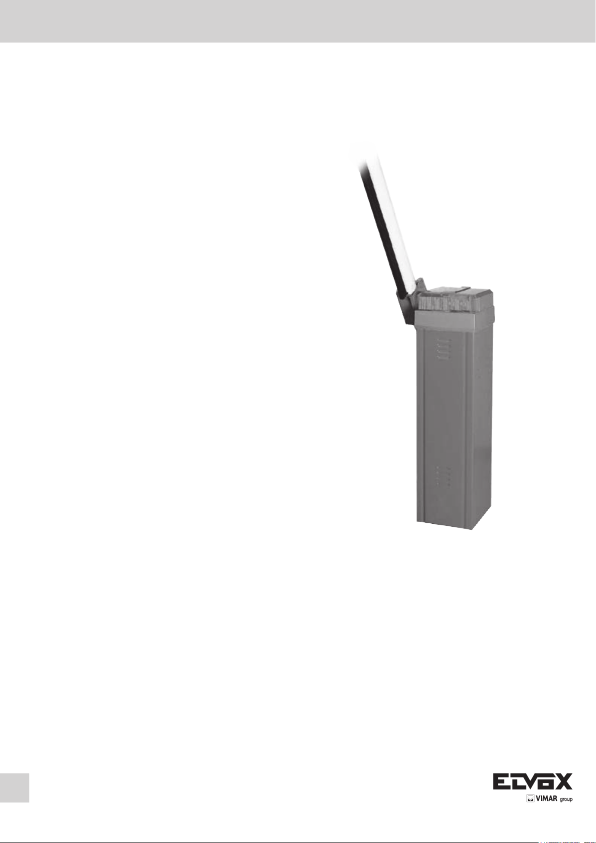
FRAGMA 6A
EBR2
Barriera 230 V per aste da 5/6 m
Barrier 230 V for bars up to 5/6 m long
Barrière 230 V pour barres de 5/6 m
Barrera 230 V para barras de 5/6 m
Schranke 230 V für Stangen 5/6 m
Σύστημα μπάρας 230 V για μπάρες 5/6 m
Page 2

FRAGMA
ISTRUZIONI DI SICUREZZA IMPORTANTI
PER L’INSTALLAZIONE
- ATTENZIONE -
PER LA SICUREZZA DELLE PERSONE É IMPORTANTE
CHE VENGANO SEGUITE TUTTE LE ISTRUZIONI
SEGUIRE TUTTE LE ISTRUZIONI DI INSTALLAZIONE
1° - Questo libretto d’istruzioni è rivolto esclusivamente a
del personale specializzato che sia a conoscenza dei criteri
costruttivi e dei dispositivi di protezione contro gli infortuni per
i cancelli, le porte e i portoni motorizzati (attenersi alle norme
e alle leggi vigenti).
2° - L’installatore dovrà rilasciare all’utente finale un libretto di
istruzioni in accordo alla EN 12635.
3° - L’installatore prima di procedere con l’installazione deve
prevedere l’analisi dei rischi della chiusura automatizzata
finale e la messa in sicurezza dei punti pericolosi identificati
(seguendo le norme EN 12453/EN 12445).
4° - Il cablaggio dei vari componenti elettrici esterni all’operatore
(ad esempio fotocellule, lampeggianti, ecc.) deve essere
effettuato secondo la EN 60204-1 e le modifiche a questa
apportate dal punto 5.2.2 della EN 12453.
5° - L’eventuale montaggio di una pulsantiera per il comando
manuale del movimento deve essere fatto posizionando la
pulsantiera in modo che chi la aziona non si trovi in posizione
pericolosa; inoltre si dovrà fare in modo che sia ridotto il
rischio di azionamento accidentale dei pulsanti.
6° - Tenete i comandi dell’automatismo (pulsantiera, telecomando
etc.) fuori dalla portata dei bambini. I comandi devono essere
posti ad un’altezza minima di 1,5 m dal suolo e fuori dal
raggio d’azione delle parti mobili.
7° - Prima di eseguire qualsiasi operazione di installazione,
regolazione, manutenzione dell’impianto, togliere la tensione
agendo sull’apposito interruttore magnetotermico collegato a
monte dello stesso.
CONSERVARE CON CURA QUESTE ISTRUZIONI
1° - Se non é previsto nella centralina elettrica, installare a
monte della medesima un’interruttore di tipo magnetotermico
(onnipolare con apertura minima dei contatti pari a 3mm) che
riporti un marchio di conformità alle normative internazionali.
Tale dispositivo deve essere protetto contro la richiusura
accidentale (ad esempio installandolo dentro quadro chiuso
a chiave).
2° - Per la sezione ed il tipo dei cavi la ELVOX consiglia di
utilizzare un cavo di tipo H05RN-F con sezione minima di
1,5mm2 e comunque di attenersi alla norma IEC 364 e alle
norme di installazione vigenti nel proprio Paese.
3° - Posizionamento di un’eventuale coppia di fotocellule: Il
raggio delle fotocellule deve essere ad un’altezza non
superiore a 70 cm dal suolo e ad una distanza dal piano di
movimento dell’anta non superiore a 20 cm. Il loro corretto
funzionamento deve essere verificato a fine installazione in
accordo al punto 7.2.1 della EN 12445.
N.B.: È obbligatoria la messa a terra dell’impianto
I dati descritti nel presente manuale sono puramente indicativi.
ELVOX si riserva di modificarli in qualsiasi momento.
Realizzare l’impianto in ottemperanza alle norme ed alle leggi
vigenti.
LA DITTA ELVOX NON ACCETTA NESSUNA RESPONSABILITÀ
per eventuali danni provocati dalla mancata osservanza
nell’installazione delle norme di sicurezza e delle leggi attualmente
in vigore.
Direttiva 2002/96/CE (WEEE, RAEE).
Il simbolo del cestino barrato riportato sull’apparecchio indica che il prodotto, alla fine della propria vita utile, dovendo essere trattato separatamente dai rifiuti domestici, deve
essere conferito in un centro di raccolta differenziata per apparecchiature elettriche ed elettroniche oppure riconsegnato al rivenditore al momento dell’acquisto di una nuova
apparecchiatura equivalente.
L’utente è responsabile del conferimento dell’apparecchio a fine vita alle appropriate strutture di raccolta. L’adeguata raccolta differenziata per l’avvio successivo dell’apparecchio
dismesso al riciclaggio, al trattamento e allo smaltimento ambientalmente compatibile contribuisce ad evitare possibili effetti negativi sull’ambiente e sulla salute e favorisce
il riciclo dei materiali di cui è composto il prodotto. Per informazioni più dettagliate inerenti i sistemi di raccolta disponibili, rivolgersi al servizio locale di smaltimento rifiuti, o al
negozio in cui è stato effettuato l’acquisto.
Rischi legati alle sostanze considerate pericolose (WEEE).
Secondo la nuova Direttiva WEEE sostanze che da tempo sono utilizzate comunemente su apparecchi elettrici ed elettronici sono considerate sostanze pericolose per le
persone e l’ambiente. L’adeguata raccolta differenziata per l’avvio successivo dell’apparecchio dismesso al riciclaggio, al trattamento e allo smaltimento ambientalmente
compatibile contribuisce ad evitare possibili effetti negativi sull’ambiente e sulla salute e favorisce il riciclo dei materiali di cui è composto il prodotto.
2
I
Page 3
FRAGMA
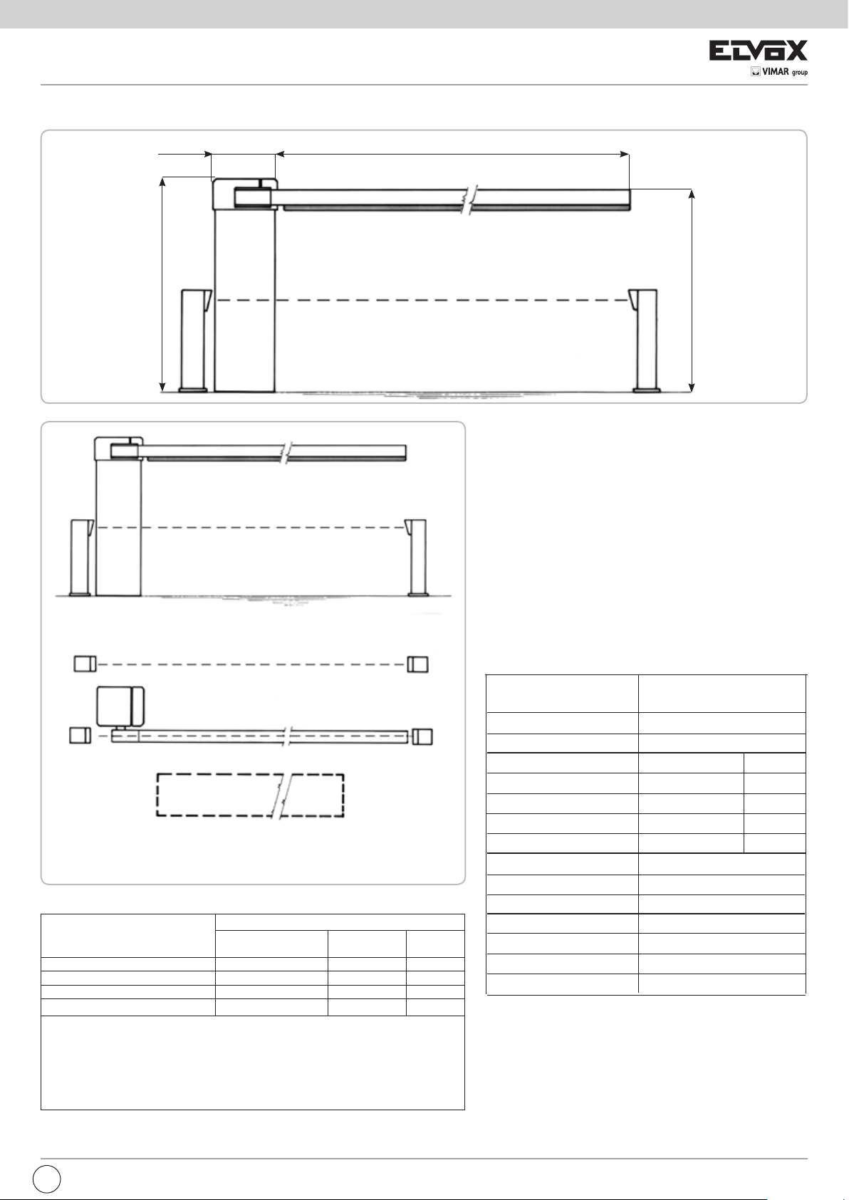
LAYOUT IMPIANTO
280x300
1065
6000
Misure in
mm
1000
1
CARATTERISTICHE TECNICHE
1
2
3
4
2
3
Attuatore irreversibile ambidestro, con centrale incorporata,
utilizzato per movimentare in modo intensivo aste lunghe da
3 a 6 m.
La colonna è protetta con cataforesi e verniciatura
termoindurente.
L’asta della barriera con profilo ELVOX è predisposta per
l’inserimento di una costa pneumatica.
N.B. È obbligatorio uniformare le caratteristiche dell’impianto
alle norme e leggi vigenti.
2
2
3 3
2
3
2
3
5
1 - Barriera FRAGMA 6A
2 - Fotocellule di sicurezza
3 - Colonnina porta fotocellula zincata
4 - Profilo in gomma
Componenti da installare secondo la norma EN12453
TIPO DI COMANDO USO DELLA CHIUSURA
Persone esperte Persone esperte
(fuori da area pubblica*) (area pubblica)
a uomo presente A B
a impulsi in vista (es. sensore) C C C e D
a impulsi non in vista (es. telecomando) C C e D C e D
automatico C e D C e D C e D
* esempio tipico sono le chiusure che non accedono a pubblica via
A: Pulsante di comando a uomo presente (cioè ad azione mantenuta).
B: Selettore a chiave a uomo presente, come cod. EDS1.
C: Gomme come cod. EBRG e/o altri dispositivi di limitazione delle forze entro i limiti della norma
EN12453 - Appendice A.
D: Fotocellule, come cod. EFA1.
5 - Sensore magnetico
- Selettore a chiave
- Antenna radio
Uso illimitato
CARATTERISTICHE
TECNICHE
Lunghezza max. asta
Tempo di apertura
Alimentazione e frequenza
Potenza motore
Assorbimento
Condensatore
Coppia max sull’albero porta asta
2
Cicli consigliati al giorno
Servizio
Cicli consecutivi garantiti
Tipo di olio
Peso max
Temperatura di lavoro
Grado di protezione
FRAGMA 6A
m 6
s 6
230 V~ 50 Hz 60 Hz
W 242 285
A 1,07 1,31
μF 10 10
Nm 155 141
n° 1500
100 %
n° 1500
SHELL OMALA S2 G100
kg 62
°C -10 ÷ +55
IP 54
FISSAGGIO FRAGMA 6A
Dopo aver cementato il basamento di fissaggio (cod. EBRB)
nella posizione ritenuta ideale, procedere nel fissaggio della
FRAGMA 6A utilizzando i dadi in dotazione e una chiave
esagonale n° 19.
I
1
Page 4
FRAGMA
GUIDA ALLA SCELTA MOLLE
Lunghezza
asta
3 m
4 m
5 m
6 m Asta e mozzo EBRA.680 + EBRM.80 3 molle Ø 5,5 3xEBRM.5.5 15
Configurazione asta
e accessori
Asta e mozzo EBRA.380 + EBRM.80 3 molle Ø 4 mm 3xEBRM.4 20
Asta, mozzo e appoggio mobile EBRA.380 + EBRM.80 + EBRP.M 2 molle Ø 4,5 mm 2xEBRM.4.5 20
Asta, mozzo e prolo gomma EBRA.380 + EBRM.80 + EBRG.3 2 molle Ø 4,5 mm 2xEBRM.4.5 20
Asta, mozzo e siepe EBRA.380 + EBRM.80 + EBRS.3 2 molle Ø 4,5 mm 2xEBRM.4.5 20
Asta, mozzo, prolo gomma e appoggio mobile EBRA.380 + EBRM.80 + EBRG.3 + EBRP.M 2 molle Ø 4,5 mm 2xEBRM.4.5 25
Asta, mozzo, siepe e appoggio mobile EBRA.380 + EBRM.80 + EBRS.3 + EBRP.M 2 molle Ø 4,5 mm 2xEBRM.4.5 25
Asta e mozzo EBRA.480 + EBRM.80 1 molla Ø 4 mm, 2 molle Ø 4,5 mm 1xEBRM.4 + 2xEBRM.4.5 20
Asta, mozzo e appoggio mobile EBRA.480 + EBRM.80 + EBRP.M 3 molle Ø 4,5 mm 3xEBRM.4.5 20
Asta, mozzo e prolo gomma EBRA.480 + EBRM.80 + EBRG.4 3 molle Ø 4,5 mm 3xEBRM.4.5 20
Asta, mozzo e siepe EBRA.480 + EBRM.80 + 2xEBRS.2 3 molle Ø 4,5 mm 3xEBRM.4.5 20
Asta, mozzo, prolo gomma e appoggio mobile EBRA.480 + EBRM.80 + EBRG.4 + EBRP.M 2 molle Ø 4,5 mm, 1 molla Ø 5 mm 2xEBRM.4.5 + 1xEBRM.5 20
asta, mozzo, siepe e appoggio mobile EBRA.480 + EBRM.80 + 2xEBRS.2 + EBRP.M 1 molla Ø 4,5 mm, 2 molle Ø 5 mm 1xEBRM.4.5 + 2xEBRM.5 20
Asta e mozzo EBRA.580 + EBRM.80 1 molla Ø 4,5 mm, 2 molle Ø 5 mm 1xEBRM.4.5 + 2xEBRM.5 20
Asta, mozzo e appoggio mobile EBRA.580 + EBRM.80 + EBRP.M 2 molle Ø 5 mm, 1 molla Ø 5,5 mm 2xEBRM.5 + 1xEBRM.5.5 15
Asta, mozzo e prolo gomma EBRA.580 + EBRM.80 + EBRG.5 2 molle Ø 5 mm, 1 molla Ø 5,5 mm 2xEBRM.5 + 1xEBRM.5.5 15
Asta, mozzo e siepe EBRA.580 + EBRM.80+EBRS.2+EBRS.3 1 molla Ø 5 mm, 2 molle Ø 5,5 mm 1xEBRM.5 + 2xEBRM.5.5 15
Asta, mozzo, prolo gomma e appoggio mobile EBRA.580 + EBRM.80 + EBRG.5 + EBRP.M 3 molle Ø 5,5 3xEBRM.5.5 20
Asta, mozzo, siepe e appoggio mobile EBRA.580 + EBRM.80+EBRS.2+EBRS.3 + EBRP.M 3 molle Ø 5,5 3xEBRM.5.5 20
Codici asta
e accessori
Molle da installare Codici molle Tiraggio
Vedi paragrafo “Regolazione molle di bilanciamento”
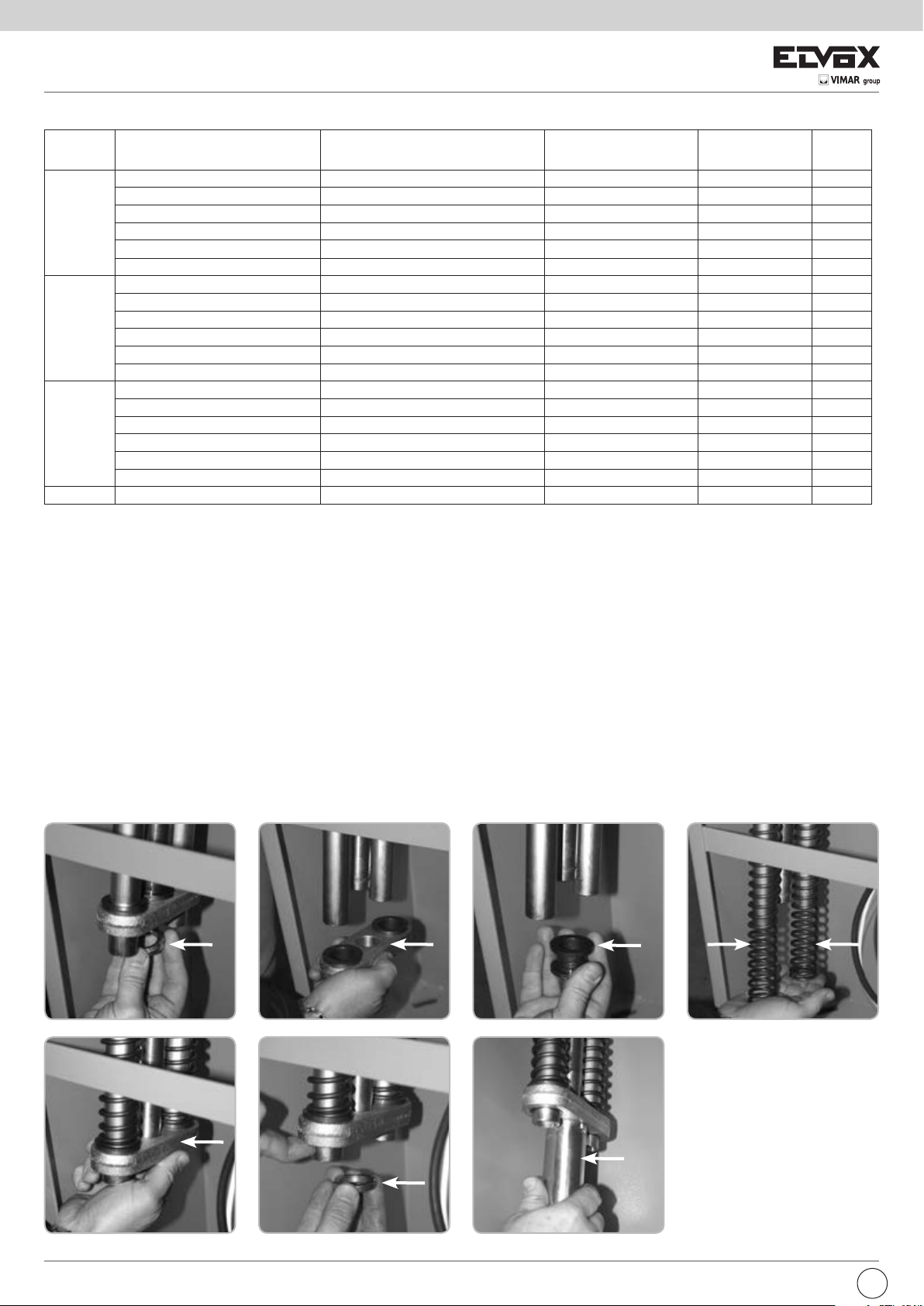
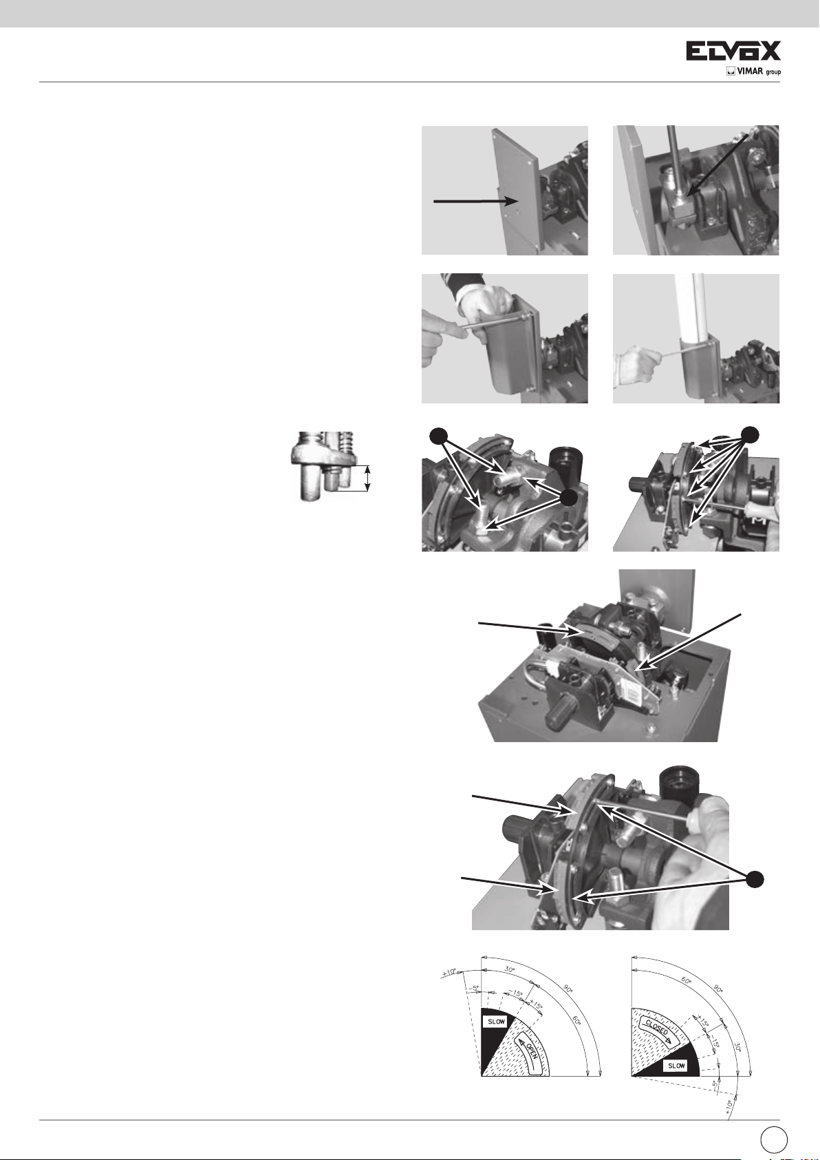
MONTAGGIO 2 MOLLE DI BILANCIAMENTO
Togliere il contenitore del quadro elettronico in modo da creare spazio all’interno della colonna.
Fig. 1 - Svitare le due ghiere.
Fig. 2 - Rimuovere il bilanciere inferiore.
Fig. 3 - Togliere i due inserti plastici tondi dal tubo centrale in quanto utilizzati solo per il montaggio della terza molla.
Fig. 4 - Inserire le due molle sui tubi laterali. N.B. La scelta delle molle deve essere eseguita secondo la TABELLA SCELTA E REGOLAZIONE MOLLE.
Fig. 5 - Calzare il bilanciere inferiore in modo che la superficie dei due inserti plastici vada a contatto con le molle laterali.
Fig. 6 - Avvitare la prima ghiera in modo che il lato con la superficie liscia più grande vada a contatto con il bilanciere.
Fig. 7 - N.B.: AVVITARE LA GHIERA COME DA TABELLA SUPERIORE (TIRAGGIO H - vedere paragrafo “Regolazione molle di bilanciamento)) con
l’apposita chiave in dotazione.
Avvitare la seconda ghiera in modo da bloccare la prima.
Procedere con il montaggio dell’asta secondo le indicazioni descritte nel paragrafo “MONTAGGIO ASTA”.
1
5
2
6
2
3
4
7
I
Page 5
FRAGMA
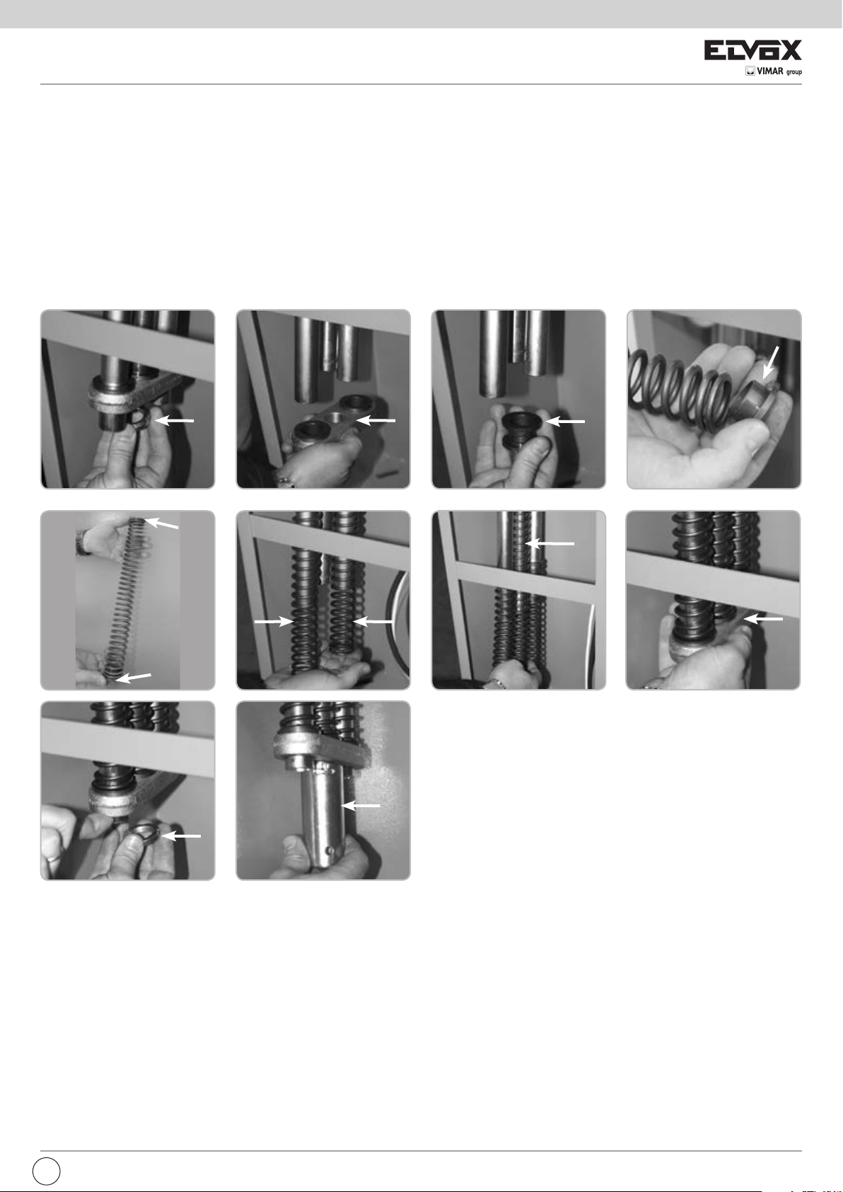
MONTAGGIO 3 MOLLE DI BILANCIAMENTO
Togliere il contenitore del quadro elettronico in modo da creare spazio all’interno della colonna.
Fig. 1 - Svitare le due ghiere.
Fig. 2 - Rimuovere il bilanciere inferiore.
Fig. 3 - Togliere i due inserti plastici tondi dal tubo centrale.
Fig. 4-5 - Montare gli inserti sulla molla che verrà inserita nel tubo centrale.
Fig. 6 - Inserire le altre due molle sui tubi laterali.
Fig. 7 - Inserire la molla appena assemblata nel tubo centrale.
Fig. 8 - Calzare il bilanciere inferiore in modo che la superficie dei due inserti plastici vada a contatto con le molle laterali.
Fig. 9 - Avvitare la prima ghiera in modo che il lato con la superficie liscia più grande vada a contatto con il bilanciere.
Fig. 10 - N.B. AVVITARE LA GHIERA COME DA TABELLA A PAGINA 4 (TIRAGGIO H -
Avvitare la seconda ghiera in modo da bloccare la prima.
Procedere con il montaggio dell’asta secondo le indicazioni descritte nel paragrafo “MONTAGGIO ASTA”.
con l’apposita chiave in dotazione
.
vedere paragrafo “Regolazione molle di bilanciamento
)
1
5
9
2
6
10
3
7
4
8
I
3
Page 6
FRAGMA
MONTAGGIO ASTA
Il montaggio dell’asta viene effettuato in 3 fasi:
1 - Inserire il mozzo porta asta in posizione verticale sull’albero
scanalato (Fig. 3).
Fissare la contropiastra al mozzo con 2 viti DTB10X50, 2 rondelle
DRL10X20Z e 2 dadi autobloccanti M10 (Fig. 4), facendo attenzione
a serrare le viti in modo alternato in maniera che la contropiastra
risulti parallela al piano del mozzo.
2 - Fissare il cavallotto alla base del porta mozzo, mediante le quattro
viti DTB8X20I e le relative rondelle. Non serrare completamente le
viti in modo da consentire il successivo inserimento dell’asta (Fig. 5).
3 - Applicare i due tappi in plastica alle estremità dell’asta ed infilare
l’asta nel mozzo. Serrare con forza le quattro viti DTB8X20I (Fig. 6).
L’operatore è di tipo irreversibile e non necessita di alcun tipo di
bloccaggio esterno per mantenere un’efficace posizione di chiusura.
REGOLAZIONE MOLLE DI BILANCIAMENTO
Normalmente la barriera viene fornita priva di molle di bilanciamento.
È necessario acquistare molle di bilanciamento di tipo e numero
corrispondente alla lunghezza e al tipo di asta ed al tipo e numero di
accessori installati.
Con operatore sbloccato, se l’asta tende a precipitare, agire sulle molle
di bilanciamento nel seguente modo:
1 - A motoriduttore bloccato sollevare elettricamente
l’asta fino alla verticale.
2 - Dopo aver tolto l’alimentazione elettrica al
motore, avvitare la ghiera di regolazione del
bilanciamento in senso orario in modo tale
da aumentare il grado di compressione delle molle durante il
movimento. Utilizzare la seconda ghiera per bloccare la prima.
Per verificare il corretto bilanciamento dell’asta sbloccare il motoriduttore
e muovere l’asta con la mano. L’asta deve leggermente tendere a salire.
H mm
G
3
5 6
F
7
4
E
8
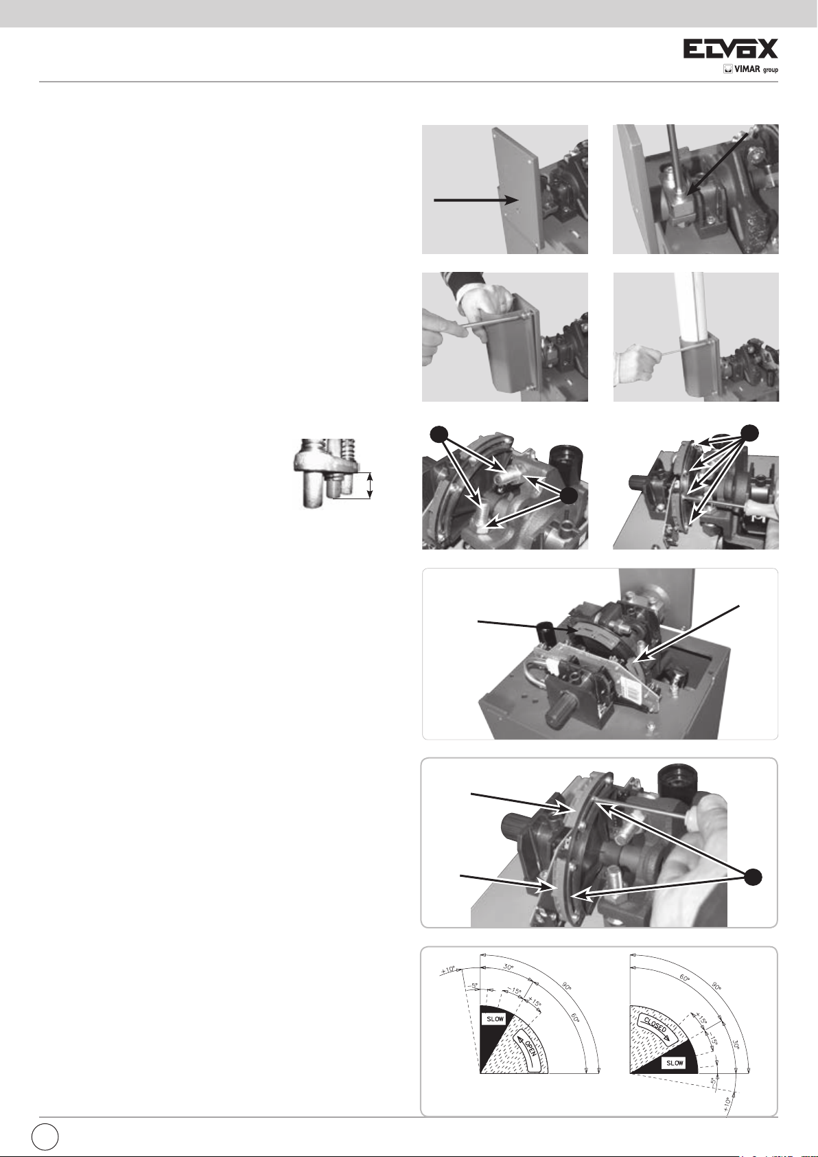
REGOLAZIONE FINECORSA
Normalmente la barriera viene fornita con i finecorsa già regolati per
permettere il movimento ideale dell’asta.
In caso di errato livellamento della piastra da cementare, l’asta potrebbe
non risultare perfettamente orizzontale o verticale con un conseguente
cattivo risultato estetico dell’installazione.
Per ovviare a ciò è possibile modificare la corsa dell’asta intervenendo
sui finecorsa meccanici (Fig. 7):
1 - A barriera sbloccata, utilizzare una chiave esagonale n° 19 per
sbloccare i dadi di fermo (F) e una chiave a brugola n° 8 per svitare
o riavvitare le viti a testa svasata (G) di regolazione dei finecorsa
meccanici in modo da delimitare immediatamente il nuovo arco
descritto dall’asta della barriera.
2 - Così facendo i finecorsa elettrici sono ora da regolare in modo tale
da delimitare il movimento elettrico del motore per la nuova corsa
che l’asta deve descrivere. Per far ciò è necessario utilizzare un
cacciavite a stella con il quale vengono allentate le viti di fissaggio
(E) delle camme del finecorsa elettrico (Fig. 8). Una volta che l’asta
è posizionata in base alla battuta di fermo meccanico è sufficiente
spostare le camme come rappresentato in Fig. 9 in modo tale da far
scattare il microinterruttore di finecorsa.
3 - Ribloccare la vite di fissaggio (E).
REGOLAZIONE RALLENTAMENTO
Normalmente la barriera viene fornita con i finecorsa di rallentamento
già regolati per permettere il movimento ideale dell’asta.
Nel caso vi fosse la necessità di modificare i parametri di rallentamento
è sufficiente intervenire sulle relative camme (Fig. 10) allentando con un
cacciavite a stella le viti di fissaggio K (Fig. 10).
Le camme di rallentamento sono indipendenti dalle camme di regolazione
del finecorsa (muovendole le camme di Chiusura e di Apertura non
vengono modificate) e sono tra loro separate (Rallentamento Apertura
- Rallentamento Chiusura).
Una volta regolate, ribloccare la vite di fissaggio e verificare facendo
eseguire un movimento completo di apertura e chiusura dell’asta il
regolare funzionamento della barriera.
CAMME
CHIUSURA
CAMME RALLENTAMENTO
CHIUSURA
CAMME
RALLENTAMENTO
APERTURA
CAMME
APERTURA
9
K
10
11
4
I
Page 7

FRAGMA
SBLOCCO DI EMERGENZA
Da effettuare dopo aver tolto l’alimentazione elettrica al motore.
In caso di mancanza di corrente, per poter aprire manualmente la sbarra
è necessario sbloccare l’elettroriduttore.
Per far ciò si utilizza la chiave ELVOX in dotazione e la si gira
manualmente in senso orario fino al fermo (Fig. 12).
In questo modo l’asta della barriera è indipendente dal riduttore e la si
può muovere manualmente.
Una volta tornata la corrente si gira la chiave in senso antiorario fino a
bloccare con forza.
MANUTENZIONE
Da effettuare solamente da parte di personale specializzato dopo
aver tolto l’alimentazione elettrica al motore.
Ogni 100.000 manovre complete verificare:
- il bilanciamento dell’asta (vedi capitolo “REGOLAZIONE MOLLE DI
BILANCIAMENTO”);
- il serraggio della manopola di sblocco (vedi capitolo “SBLOCCO DI
EMERGENZA”);
- il serraggio del mozzo e il fissaggio dell’asta (vedi capitolo “MONTAGGIO
ASTA”);
- l’usura delle battute di fermo meccanico e la regolazione dei finecorsa
(vedi capitolo “REGOLAZIONE FINECORSA”);
- inoltre, ingrassare i supporti dell’albero porta asta e la barra filettata
12
guidamolla.
La manutenzione sopra descritta è vitale per il corretto
funzionamento del prodotto nel tempo.
COLLEGAMENTI ELETTRICI
A - CONNESSIONI
J4
J1
S3
TR2
J9
J5
J2
J3
J10
J8
J7
J6
J1
J2
J3
J4
J5
J6
J7
J8
J9
J10
S3
TR2
L-N
COM
LSC
LSO
LSSC
LSSO
TLC
PHOT. NC
EDGE NC
COM
D+ TEST
D+
D-
OPEN 2
SIGNAL
AERIAL
U - MOTOR
V-W - MOTOR
OK CLOSE
OPEN 1
CLOSE
STOP
K BUTT.
COM
PROBE
RADIO
AUX. ATT.
SW PARK
SW RADIO
PROG.
TRIMMER LOW
SPEED
RS15
Alimentazione 230 Vac 50/60 Hz
Comune dei contatti
Contatto finecorsa che ferma la chiusura (NC)
Contatto finecorsa che ferma l’apertura (NC)
Contatto finecorsa per inizio rallentamento in chiusura (NO)
Contatto finecorsa per inizio rallentamento in apertura (NO)
Contatto segnalazione presenza veicolo (NO) (solo in modalità
PARK)
Contatto fotocellule (NC)
Comune dei contatti
Positivo per alimentazione autotest costa a 12 Vdc max 500 mA
Positivo Alimentazione accessori a 12 Vdc max 500 mA
Negativo per alimentazione accessori a 12 Vdc max 500 mA
Contatto pulsante di apertura 2 (NA) (solo in modalità PARK)
Spia barriera aperta 12 Vdc
Buzzer - Collegamento segnalatore sonoro (12 Vdc max 200 mA)
Antenna radio
Lampeggiatore (max 40 W )
Collegamento comune motore
Collegamento invertitori e condensatore motore
Contatto comando chiusura immediata (solo in modalità PARK)
Contatto pulsante di apertura 1 (NA)
Contatto pulsante di chiusura (NA)
Contatto pulsante stop (NC)
Contatto impulso singolo (NA)
Comune dei contatti
-
Modulo radio incorporato
-
NON TOCCARE IL PONTICELLO !
SE VIENE RIMOSSO L’OPERATORE NON FUNZIONA!
NON TOCCARE IL PONTICELLO !
SE VIENE RIMOSSO IL RADIOCOMANDO NON FUNZIONA!
Pulsante per la programmazione.
Regolazione della velocità di rallentamento solo in
chiusura
I
5
Page 8

FRAGMA
RELE’ E COMANDO MOTORE
K1 => Comando direzione apertura
K2 => Comando direzione chiusura
Q4 => TRIAC - Comando motore in apertura e chiusura
Q5 => Comando lampeggiatore
B - SETTAGGI
SW1 SW2 - MICROINTERRUTTORI PER PROCEDURE
DIP 1 - CONTROLLO SENSO DI ROTAZIONE DEL MOTORE (ON)
(PUNTO C)
DIP 2 - PROGRAMMAZIONE TEMPI (ON) (PUNTO D)
DIP 1-2 MEMORIZZAZIONE/CANCELLAZIONE CODICI
RADIO (PUNTO E)
MICROINTERRUTTORI DI GESTIONE
DIP 3
ON - Abilitazione tempo di attesa prima della chiusura automatica (max 5 min.)
OFF - Disabilitazione tempo di attesa prima della chiusura automatica
DIP 4
ON - Comando ricevitore radio in modalità Automatica
OFF - Comando ricevitore radio in modalità Passo Passo
DIP 5
ON - Comando pulsante K in modalità Automatica
OFF - Comando pulsante K in modalità Passo Passo
DIP 6
ON - Funzionamento in modalità PARK
OFF - Funzionamento in modalità NORMALE
ATTENZIONE: LA SCHEDA PARK TRAMITE IL DIP 6 ABILITA O MENO ALCUNI
COMANDI PERTANTO PRESTARE ATTENZIONE:
SE DIP 6 OFF - FUNZIONALITA’ NORMALE
I COMANDI APERTURA 2, OK CLOSE E TLC (TRAFFIC LIGHT CONTROL)
NON SONO ATTIVI.
SE DIP 6 ON - FUNZIONALITA’ PARK
TUTTI I COMANDI SONO ABILITATI
DIP 7 OFF
DIP 8 - Controllo in modalità Park della funzione del tasto APERTURA 2
ON - il tasto APERTURA 2 è sempre abilitato
OFF - il tasto APERTURA 2 è abilitato solo se non c’è presenza mezzo su sensore
magnetico collegato a TLC (Traffic Light Control)
DIP 9 OFF
DIP 10 - Funzionamento dopo black-out
ON - La sbarra chiude se non totalmente chiusa
OFF - La sbarra rimane ferma nel punto in cui è avvenuto il black-out
DIP 11 OFF
DIP 12 OFF
DIP 13 - Gestione lampeggiatore
ON - Alimentazione intermittente
OFF - Alimentazione fissa
DIP 14 ON
DIP 15 OFF
DIP 16 OFF
REGOLATORE DELLA VELOCITA’ DI RALLENTAMENTO
La regolazione del rallentamento viene fatta ruotando il Trimmer LOW SPEED
che serve a variare la velocità del motore in fase di accostamento di fine chiusura
(ruotandolo in senso orario si da più velocità al motore). In apertura la regolazione
non è disponibile.
Il rallentamento viene determinato automaticamente dai finecorsa a circa 30° prima
del raggiungimento del finecorsa di apertura o di chiusura.
SEGNALAZIONI LED
DL1 - (Rosso) - Programmazione attivata
DL2 - (Rosso) - Contatto di stop (NC)
DL3 - (Verde) - Sbarra in apertura
DL4 - (Rosso) - Sbarra in chiusura
DL5 - (Rosso) - Contatto fotocellule (NC)
DL6 - (Rosso) - Contatto costa (NC)
DL7 - (Rosso) - Contatto finecorsa di chiusura (NC)
DL8 - (Rosso) - Contatto finecorsa di apertura (NC)
DL9 - (Verde) - Programmazione radio attivata
C - TARATURA RALLENTAMENTO DEL MOTORE
Questo controllo ha il compito di agevolare l’installatore durante la messa in opera
dell’impianto, o durante eventuali controlli successivi.
1 - Mettere DIP1 su ON, il led rosso DL1 inizia a lampeggiare.
2 - Premere e mantenere premuto il pulsante PROG (il movimento è eseguito ad
uomo presente, apre-stop-chiude-stop-apre-ecc.). Con il led verde DL3 acceso, la
sbarra si apre. Con il led rosso DL4 acceso, la sbarra si chiude.
3 - Eseguire la taratura della velocità di rallentamento:
- Posizionare il trimmer LOW SPEED al minimo
- Premere e mantenere premuto il pulsante PROG
- Verificare l’attivazione della velocità di rallentamento al raggiungimento dei
- Regolare il trimmer LOW SPEED.
ATTENZIONE: Verificare che il motore abbia abbastanza forza per movimentare
ATTENZIONE: In zone soggette a temperature particolarmente rigide, ruotare il
4 - Al termine del controllo rimettere DIP1 in posizione OFF => Il led DL1 si spegne
N.B.: Durante questo controllo la costa e le fotocellule non sono attivi.
D - PROGRAMMAZIONE TEMPI
1 - Chiudere completamente la barriera.
2 - Mettete il microinterruttore DIP 2 su ON, il led rosso DL1 inizia a lampeggiare.
3 - Premete e poi rilasciare il pulsante PROG. La sbarra apre.
4 - Raggiunto la completa apertura, la sbarra si ferma e si attiva il conteggio del tempo
5 - Quando il tempo di pausa prima della chiusura automatica è sufficiente, o nel caso
6 - La barriera chiude e, nello stesso istante, il led rosso DL1 smette di lampeggiare
7 - Riposizionare DIP 2 su OFF.
8 - Fine procedura.
DURANTE LA PROGRAMMAZIONE LE SICUREZZE SONO ATTIVE ED IL LORO
INTERVENTO FERMA LA PROGRAMMAZIONE (IL LED DL1 DA LAMPEGGIANTE
RIMANE ACCESO FISSO).
PER RIPETERE LA PROGRAMMAZIONE POSIZIONARE IL DIP 2 SU
OFF, CHIUDERE LA SBARRA TRAMITE LA PROCEDURA “TARATURA
RALLENTAMENTO DEL MOTORE” E RIPETERE LA PROGRAMMAZIONE
SOPRA DESCRITTA.
E - PROGRAMMAZIONE CODICI RADIO (40 CODICI MAX)
La programmazione può essere eseguita solo a barriera ferma.
1 - Posizionare DIP 1 su ON e successivamente il DIP 2 su ON.
2 - Il led rosso DL1 di programmazione lampeggia con frequenza di 1 sec. ON
3 - Premere il tasto del telecomando (normalmente il canale A) entro i 10
4 - Il tempo di programmazione dei codici si rinnova automaticamente per poter
5 - Per terminare la programmazione lasciare trascorrere 10 sec., oppure
6 - Riposizionare DIP 1 su OFF e DIP 2 su OFF.
7 - Fine procedura.
PROCEDURA CANCELLAZIONE DI TUTTI I CODICI RADIO
La cancellazione può essere eseguita solo a barriera ferma.
1 - Posizionare il DIP 1 su ON e successivamente il DIP 2 su ON.
2 - Il led rosso DL1 di programmazione lampeggia con frequenza di 1 sec. ON
3 - Premere e mantenere premuto il pulsante PROG per 5 secondi. La
4 - Il led rosso DL1 di programmazione rimane attivo ed è possibile inserire
5 - Riposizionare DIP 1 su OFF e DIP 2 su OFF.
6 - Fine procedura.
SEGNALAZIONE MEMORIA SATURA CODICI RADIO
La segnalazione si può ottenere solo a barriera ferma.
1 - Posizionare il DIP 1 su ON e successivamente il DIP 2 su ON.
2 - Il led verde DL9 lampeggia per 6 volte segnalando memoria satura (40 codici
3 - Successivamente il led DL1 di programmazione rimane attivo per 10 secondi,
4 - Riposizionare DIP 1 su OFF e DIP 2 su OFF.
5 - Fine procedura.
FUNZIONAMENTO ACCESSORI DI COMANDO IN MODALITA’
NORMALE
PULSANTE DI APERTURA 1 (Com - Open 1)
A sbarra ferma il pulsante comanda il moto di apertura. Se viene azionato durante
finecorsa LSSC ed LSSO
l’asta in chiusura. In caso contrario aumentare il valore settato sul trimmer fino al
raggiungimento della condizione ottimale di funzionamento.
trimmer, in senso orario, di 5° in più rispetto al valore normale
segnalando l’uscita dal controllo.
d’attesa prima della chiusura automatica (max 5 minuti).
non sia necessario, premere e poi rilasciare il pulsante PROG.
segnalando l’uscita dalla procedura di apprendimento. Da questo momento le
sicurezze o altri comandi della barriera funzioneranno normalmente (inversioni,
stop, allarmi, ecc...). La chiusura della sbarra verrà eseguita in modalità veloce e
in prossimità della totale chiusura in modalità rallentata.
e 1 sec. OFF per 10 secondi.
secondi impostati. Se il telecomando viene correttamente memorizzato il led
DL9 (verde) emette un lampeggio.
memorizzare il telecomando successivo.
premere per un attimo il pulsante PROG. Il led rosso DL1 di programmazione
smette di lampeggiare.
e 1 sec. OFF per 10 secondi.
cancellazione della memoria viene segnalata da due lampeggi del led verde
DL9.
nuovi codici come da procedure sopra descritte.
presenti).
consentendo un eventuale cancellazione totale dei codici.
6
I
Page 9
FRAGMA
_
+
+
_
_
+
+
NC
D-
+
D
+D
NO
COM
SS
D-
-
+
NO
NC
D+
D-
+
D-
S
D+
+
S
COM
+
_
+
_
-
+
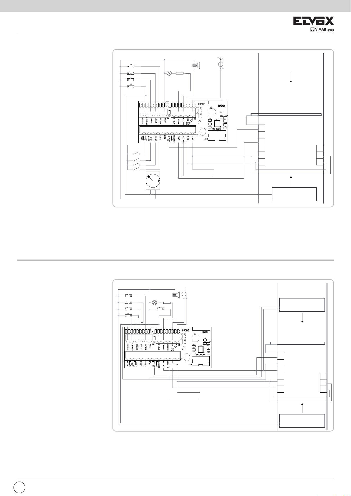
la chiusura fa riaprire la sbarra. In modalità di
funzionamento Park (DIP 6 ON) abilita l’apertura
della sbarra per entrare nel parcheggio.
FUNZIONE OROLOGIO DEL PULSANTE DI
APERTURA
La Funzione Orologio è utile nelle ore di punta,
quando il traffico veicolare risulta rallentato
(es. entrata/uscita operai, emergenze in zone
residenziali o parcheggi e, temporaneamente, per
traslochi).
MODALITÁ DI APPLICAZIONE FUNZIONE
OROLOGIO
Collegando un interruttore e/o un orologio di tipo
giornaliero/settimanale (al posto o in parallelo
al pulsante di apertura N.A. “morsetti Com Open 1”), è possibile aprire e mantenere aperta
l’automazione finché l’interruttore viene premuto
o l’orologio rimane attivo. Ad automazione aperta
vengono inibite tutte le funzioni di comando.
Rilasciando l’interruttore, o allo scadere dell’ora
impostata, si avrà la chiusura immediata
dell’automazione.
PULSANTE DI CHIUSURA (Com - Close)
A sbarra aperta comanda il moto di chiusura.
PULSANTE DI COMANDO PASSO-PASSO
(Com - K Button)
DIP5 - OFF => Esegue un comando ciclico dei
comandi apre-stop-chiude-stopapre-ecc.
DIP5 - ON => Esegue l’apertura a sbarra chiusa.
Se azionato durante il movimento
di apertura non ha effetto. Se azionato con sbarra aperta, la
chiude. Se azionato durante il movimento di chiusura la fa riaprire.
TELECOMANDO
DIP4 - OFF => Esegue un comando ciclico dei comandi apre-stop-chiude-stop-
apre-ecc.
DIP4 - ON => Esegue l’apertura a sbarra chiusa. Se azionato durante il
PASSO PASSO
STOP
CHIUDE
APRE 1
LSC
LSO
LSSC
LSSO
TIMER
LED
ANTENNA
R=2K2
BUZZER
12 Vdc max 0,5A per ACCESSORI
12 Vdc max 0,5A per AUTOTEST PER COSTA
CALZA
ANTENNA
ENTRATA
SENSORE MAGNETICO
USCITA
movimento di apertura non ha effetto. Se azionato con sbarra
aperta, la chiude. Se azionato durante il movimento di chiusura
la fa riaprire.
CHIUSURA AUTOMATICA (DIP 3)
I tempi di pausa prima di avere la chiusura automatica della sbarra vengono
registrati durante la programmazione dei tempi.
Il tempo di pausa massimo è di 5 minuti.
Il tempo di pausa è attivabile o disattivabile tramite DIP3 (ON - attivo).
FUNZIONAMENTO DELLA MODALITA’ PARK (DIP 6 ON)
PER ENTRARE:
A condizione che un’autovettura sia presente
sul sensore magnetico, può essere comandata
l’apertura della sbarra tramite pulsante
APERTURA 1, K BUTTON o comando RADIO.
La sbarra rimarrà aperta fin quando l’autovettura
non sarà transitata davanti alle fotocellule situate
in corrispondenza della linea di completamento
del passaggio.
La chiusura viene eseguita immediatamente
dopo l’avvenuto transito (fotocellula liberata), e
viene protetta da fotocellule e/o costa. Queste
comanderanno l’inversione della sbarra in
apertura anche se l’autovettura permane nel
raggio di azione delle sicurezze.
PER USCIRE:
L’apertura della sbarra è consentita tramite il
pulsante APERTURA 2 collegato ad un sensore
magnetico o altro dispositivo, a condizione che
non vi siano mezzi sul sensore magnetico di
ingresso (vedi DIP 8 per esclusione del blocco di
precedenza).
La sbarra rimarrà aperta fin quando l’autovettura
non sarà transitata davanti alle fotocellule situate
in corrispondenza della linea di completamento
del passaggio.
La chiusura viene eseguita immediatamente
dopo l’avvenuto transito (fotocellula liberata), e
viene protetta da fotocellule e/o costa. Queste
comanderanno l’inversione della sbarra in apertura anche se l’autovettura
permane nel raggio di azione delle sicurezze.
ATTENZIONE: Il tempo di attesa prima della chiusura automatica sarà conteggiato
solo se “DIP 3 ON”.
Come conseguenza se “DIP 3 ON” e se l’autoveicolo rimane troppo a lungo sul
sensore magnetico senza transitare (senza impegnare la fotocellula), la sbarra
PASSO PASSO
STOP
CHIUDE
APRE 1
LED
BUZZER
R=2K2
ANTENNA
CALZA
ANTENNA
SENSORE MAGNETICO
ENTRATA
12 Vdc max 0,5A per ACCESSORI
12 Vdc max 0,5A per AUTOTEST PER COSTA
SENSORE MAGNETICO
USCITA
chiuderà dopo il tempo preimpostato.
PULSANTE APERTURA 2 (Com - Open 2) solo per funzionamento in
modalità PARK
Comando dedicato all’apertura della sbarra per uscire dal parcheggio con
gestione della segnalazione di precedenza del semaforo.
Questo comando viene escluso se il comando TLC risulta inserito (presenza
I
7
Page 10

FRAGMA
mezzo in ingresso). Se non si desidera utilizzare il blocco di precedenza tramite
l’ingresso TLC, posizionare il DIP 8 in ON.
COMANDO OK CLOSE (Com - OK Close) solo per funzionamento in modalità
PARK
Consente la chiusura immediata della sbarra dopo che il veicolo è transitato.
Contatto NO, normalmente questo comando viene dato da una fotocellula o da un
sensore magnetico posizionato sulla linea di chiusura della sbarra.
Se il comando rimane inserito la sbarra non richiude.
COMANDO TLC - Traffic Light Control (Com - TLC) solo per funzionamento
in modalità PARK
L’ingresso “TLC” (NO) deve essere collegato ad un sensore magnetico posizionato
nelle immediate vicinanze della sbarra, in tal modo fornisce la segnalazione di
presenza di un veicolo in ingresso (se non si vuole usufruire di questa funzione
eseguire un ponticello tra i morsetti Com e TLC). Solo la presenza di un veicolo
consente l’apertura della sbarra in modalità di funzionamento PARK tramite il
comando apertura 1.
FUNZIONAMENTO DOPO BLACK OUT
Con DIP 10 - OFF => Con mancanza della tensione di rete la sbarra rimane
Con DIP 10 - ON => Al ritorno della tensione di rete la sbarra chiude se aperta,
ferma o se in movimento si ferma. Al ritorno della
tensione di rete è sufficiente premere il telecomando, i
pulsanti di APERTURA 1 o 2 o il pulsante K Button per
aprire la sbarra. A sbarra aperta date un comando di
chiusura o attendete il tempo di pausa prima della chiusura
automatica => La sbarra parte in chiusura => All’arrivo in
chiusura vengono ristabilite le funzionalità normali. Durante
il riallineamento le sicurezze sono attive.
non chiude solo nel caso in cui sia attiva la funzione
orologio (vedi pulsante di APERTURA 1).
FUNZIONAMENTO ACCESSORI DI SICUREZZA
FOTOCELLULA (Com - Photo)
Con sbarra abbassata, se un ostacolo è interposto al raggio delle fotocellule e
viene comandata l’apertura, la sbarra apre (durante l’apertura le fotocellule non
interverranno).
Le fotocellule interverranno solo in fase di chiusura (con ripristino del moto inverso
dopo un secondo anche se le stesse restano impegnate).
N.B.: Si raccomanda di verificare la funzionalità delle fotocellule almeno
ogni 6 mesi.
ATTENZIONE: Se il led del ricevitore rimane acceso è possibile che siano
presenti dei disturbi sulla rete di alimentazione.
Vi consigliamo di collegare elettricamente a terra le
colonne o le colonnine di supporto alle fotocellule
al morsetto D- per proteggere le fotocellule da fonti
di disturbo.
Fate attenzione a non creare corto circuiti quando le
fasi di alimentazione sono invertite!
Mors.
D-
12 Vdc
o comunque non chiusa totalmente. Solo a barriera completamente chiusa si
spegne.
N.B.: Se si eccede con le pulsantiere o con le lampade, la logica della centralina
ne risulterà compromessa con possibile blocco delle operazioni.
CARATTERISTICHE TECNICHE
- Umidità < 95% senza condensazione
- Tensione di alimentazione 230 V~ ±10 %
- Frequenza 50/60 Hz
- Assorbimento massimo scheda 30 mA
- Microinterruzioni di rete 100 ms
- Potenza massima spia barriera aperta 3 W (equivalente a 1
lampadina da 3 W o 5 led con
resistenza in serie da 2,2 kΩ)
- Carico massimo all’uscita lampeggiatore 40 W con carico resistivo
- Corrente disponibile per fotocellule e accessori 500 mA 12 Vdc
- Corrente disponibile su connettore radio 200 mA 12 Vdc
CARATTERISTICHE TECNICHE RADIO
- Frequenza Ricezione 433,92 MHz
- Impedenza 52 Ω
- Sensibilità >2,24 µV
- Tempo eccitazione 300 ms
- Tempo diseccitazione 300 ms
- Tutti gli ingressi devono essere utilizzati come contatti puliti perchè l’alimentazione
è generata internamente (tensione sicura) alla scheda ed è disposta in modo da
garantire il rispetto di isolamento doppio o rinforzato rispetto alle parti a tensione
pericolosa.
- Eventuali circuiti esterni collegati alle uscite della centralina, devono essere
eseguiti per garantire l’isolamento doppio o rinforzato rispetto alle parti a
tensione pericolosa.
- Tutti gli ingressi vengono gestiti da un circuito integrato programmato che
esegue un autocontrollo ad ogni avvio di marcia.
PULSANTE DI STOP (Com - Stop)
Durante qualunque operazione il pulsante di STOP esegue il fermo della sbarra.
Se premuto a sbarra aperta totalmente si esclude temporaneamente la chiusura
automatica (se selezionata tramite DIP3 ON).
É quindi necessario dare un nuovo comando per farla richiudere.
Al ciclo successivo la funzione “chiusura automatica” viene riattivata (se
selezionata tramite DIP3 ON).
LAMPEGGIATORE 230 V 40 W
DIP 13 ON
Il lampeggiatore viene alimentato ad intermittenza, con lampeggio di 500 mS on/
off in apertura e 250 mS on/off in chiusura.
In allarme da costa o autotest costa, l’uscita lampeggiatore cambia l’intermittenza
con 2 brevi lampeggi seguiti da 2 secondi di spento.
BUZZER (Opzionale) - (Com - Buzzer)
Durante l’apertura il buzzer darà un segnale sonoro intermittente che diventa più
frequente in chiusura.
In caso di intervento delle sicurezze (allarme) questo segnale sonoro aumenta la
frequenza dell’intermittenza.
Corrente fornita per il funzionamento del buzzer 200 mA a 12 Vdc.
SPIA DI SEGNALAZIONE BARRIERA APERTA (Com-Signal)
Ha il compito di segnalare gli stati della barriera aperta, parzialmente aperta
8
I
Page 11
FRAGMA
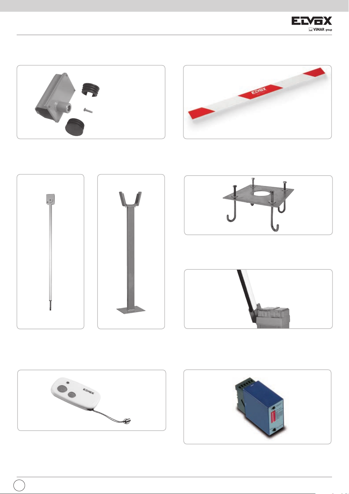
OPTIONAL - Per i collegamenti ed i dati tecnici degli accessori attenersi ai relativi libretti di istruzione.
MOZZO
PALETTO PENDULO PER
ASTA Ø 80
ADESIVI
per asta Ø 80 mm
cod. EBRM.80
cod. ZBNE
PALETTO DI SUPPORTO
PIASTRA DI FISSAGGIO
TELECOMANDO
Cod. EBRP.M
Paletto di supporto a forcella
compatibile con tutte le aste.
cod. EBRP
Piastra di fissaggio da interrare cod. EBRB
GOMMA
cod. EBRG
SENSORE A SPIRA MAGNETICA
cod. ETR5
Per apertura con automezzi
monocanale - 12-24 Vac/dc cod. ZR01
I
9
Page 12

FRAGMA
DICHIARAZIONE CE DI CONFORMITA’
(Dichiarazione di incorporazione di quasi-macchine allegato IIB Direttiva 2006/42/CE)
Il sottoscritto, rappresentante il seguente costruttore
35011 Campodarsego (PD) Italy
dichiara qui di seguito che i prodotti
ATTUATORI PER BARRIERE STRADALI - SERIE FRAGMA
Articoli
FRAGMA 3D, FRAGMA 4A, FRAGMA 6A
No. : ZDT00443.00
Elvox SpA
Via Pontarola, 14/a
risultano in conformità a quanto previsto dalla(e) seguente(i) direttiva(e) comunitaria(e) (comprese tutte le modifiche
applicabili) e che sono state applicate tutte le seguenti norme e/o specifiche tecniche:
Direttiva BT 2006/95/CE: EN 60335-2-103 (2003) + A11 (2009)
Direttiva EMC 2004/108/CE: EN 61000-6-1 (2007), EN 61000-6-3 (2007) + A1 (2011)
EN 61000-6-2 (2005), EN 61000-6-4 (2007) + A1 (2011)
Direttiva R&TTE 1999/5/CE: EN 301 489-3 (2002), EN 300 220-3 (2000)
Direttiva Macchine 2006/42/CE EN 13241 (2003) + A1 (2011), EN 12453 (2000)
Dichiara inoltre che la messa in servizio del prodotto non deve avvenire prima che la macchina finale, in cui deve essere
incorporato, non è stata dichiarata conforme, se del caso, alle disposizioni della Direttiva 2006/42/CE.
Dichiara che la documentazione tecnica pertinente è stata costituita da Elvox SpA, è stata compilata in conformità
all’allegato VIIB della Direttiva 2006/42/CE e che sono stati rispettati i seguenti requisiti essenziali: 1.1.1, 1.1.2, 1.1.3,
1.1.5, 1.1.6, 1.2.1, 1.2.2, 1.2.6, 1.3.1, 1.3.2, 1.3.3, 1.3.4, 1.3.7, 1.3.8, 1.3.9, 1.4.1, 1.4.2, 1.5.1, 1.5.2, 1.5.4, 1.5.5, 1.5.6,
1.5.7, 1.5.8, 1.5.9, 1.6.1., 1.6.2, 1.7.1, 1.7.2, 1.7.3, 1.7.4, 4.1.2.
Si impegna a presentare, in risposta ad una richiesta adeguatamente motivata delle autorità nazionali, tutta la
necessaria documentazione giustificativa pertinente al prodotto.
Campodarsego, 06/05/2013
L’Amministratore Delegato
Nota: Il contenuto di questa dichiarazione corrisponde a quanto dichiarato nell’ultima revisione della dichiarazione ufficiale disponibile
prima della stampa di questo manuale. Il presente testo è stato adattato per motivi editoriali. Copia della dichiarazione originale può essere
richiesta a Elvox SpA
10
I
Page 13

FRAGMA
IMPORTANT SAFETY INSTRUCTIONS
FOR THE INSTALLATION
- ATTENTION -
FOR THE SAFETY OF THE PEOPLE IT IS IMPORTANT
TO FOLLOW ALL THE INSTRUCTIONS.
FOLLOW ALL INSTALLATION INSTRUCTIONS
1° - This handbook is exclusively addressed to the specialized
personnel who knows the constructive criteria and the
protection devices against the accidents for motorized gates,
doors and main doors (follow the standards and the laws in
force).
2° - The installer will have to issue to the final user a handbook in
accordance with the EN 12635.
3° - Before proceeding with the installation, the installer must
forecast the risks analysis of the final automatized closing
and the safety of the identified dangerous points (following
the standards EN 12453/EN 12445).
4° - The wiring harness of the different electric components
external to the operator (for example photoelectric cells,
flashlights etc.) must be carried out according to the EN
60204-1 and the modifications to it done in the point 5.2.2 of
the EN 12453.
5° - The possible assembly of a keyboard for the manual control
of the movement must be done by positioning the keyboard
so that the person operating it does not find himself in
a dangerous position; moreover, the risk of accidental
activation of the buttons must be reduced.
6° - Keep the automatism controls (push-button panel, remote
control etc.) out of the children way. The controls must be
placed at a minimum height of 1,5 m from the ground and
outside the range of the mobile parts.
7° - Before carrying out any installation, regulation or maintenance
operation of the system, take off the voltage by operating on
the special magnetothermic switch connected upstream it.
KEEP THESE INSTRUCTIONS WITH CARE
1° - Install a thermal magnetic switch (omnipolar, with a minimum
contact opening of 3 mm) before the control board, in case
this is not provided with it. The switch shall be guaranteed
by a mark of compliance with international standards. Such
a device must be protected against accidental closing (e.g.
Installing it inside the control panel key locked container).
2° - As far as the cable section and the cable kind are concerned,
ELVOX suggests to use an H05RN-F cable, with a minimum
section of 1,5mm2, and to follow, In any case, the IEC 364
standard and Installation regulations In force In your Country.
3° - Positioning of an eventual pair of photocells: The beam of the
photocells must be at an height not above the 70 cm from the
ground, and, should not be more than 20 cm away from the
axis of operation of the gate (Sliding track for sliding gate or
door, and the hinges for the swing gate). In accordance with
the point 7.2.1 of EN 12445 their correct functioning must be
checked once the whole installation has been completed.
N.B.: The system must be grounded
Data described by this manual are only Indicative and ELVOX
reserves to modify them at any time. Install the system complying
with current standards and regulations.
THE ELVOX COMPANY DOES NOT ACCEPT ANY
RESPONSIBILITY for possible damages caused by the non
observance during the installation of the safety standards and of
the laws in force at present.
Directive 2002/96/EC (WEEE)
The crossed-out wheelie bin symbol marked on the product indicates that at the end of its useful life, the product must be handled separately from household refuse and must
therefore be assigned to a differentiated collection centre for electrical and electronic equipment or returned to the dealer upon purchase of a new, equivalent item of equipment.
The user is responsible for assigning the equipment, at the end of its life, to the appropriate collection facilities.
Suitable differentiated collection, for the purpose of subsequent recycling of decommissioned equipment and environmentally compatible treatment and disposal, helps prevent
potential negative effects on health and the environment and promotes the recycling of the materials of which the product is made. For further details regarding the collection
systems available, contact your local waste disposal service or the shop from which the equipment was purchased.
Risks connected to substances considered as dangerous (WEEE).
According to the WEEE Directive, substances since long usually used on electric and electronic appliances are considered dangerous for people and the environment.
The adequate differentiated collection for the subsequent dispatch of the appliance for the recycling, treatment and dismantling (compatible with the environment) help
to avoid possible negative effects on the environment and health and promote the recycling of material with which the product is compound.
EN
11
Page 14
FRAGMA
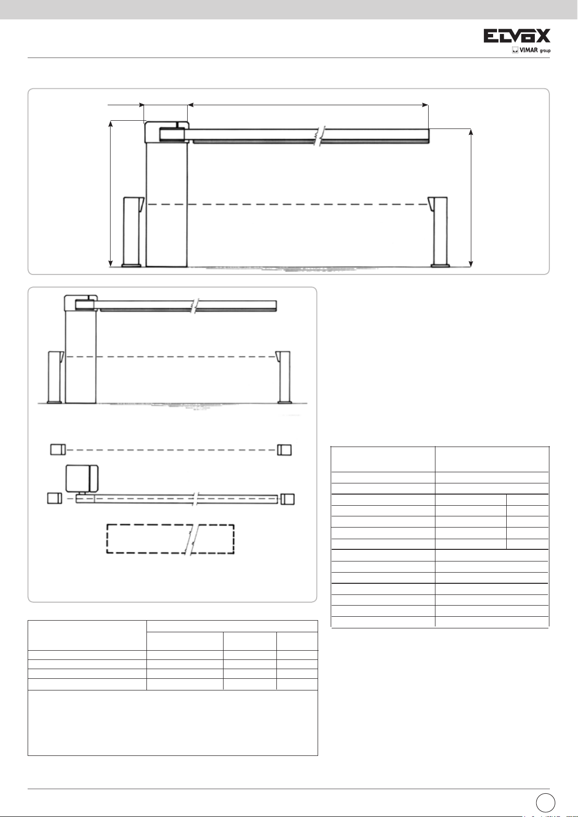
SYSTEM LAY-OUT
280/11,2”x300/12”
1065/42”
6000/236”
Measurements
in mm/inch
1000/39”
1
1
2
3
4
2
3
TECHNICAL FEATURES
Ambidextrous irreversibile operator endowed with a control
panel, used for the intesive movement of boom arms from
3 to 6 m long.
The cabinet of the operator is treated with cataphoresis and
thermal spray coating.
The barrier boom with ELVOX profile is constructed for being
fitted with a pneumatic safety strip .
N.B. You must make installation features comply with laws and
standards in force.
2
2
3 3
2
3
2
3
5
1 - FRAGMA 6A barrier
2 - Photoelectric cells
3 - Galvanized column for P.E. cells
4 - Rubber
Parts to install meeting the EN 12453 standard
COMMAND TYPE USE OF THE SHUTTER
Skilled persons Skilled persons Unrestricted
(out of a public area*) (public area) use
with manned operation A B
with visible impulses (e.g. sensor) C C C e D
with not visible impulses (e.g. remote control device)
automatic C e D C e D C e D
* a typical example are those shutters which do not have access to any public way.
A: Command button with manned operation (that is, operating as long as activated).
B: Key selector with manned operation, like code EDS1.
C: Rubber, like code
EN12453 regulation - Appendix A.
D: Photocells, like code EFA1.
and/or other safety devices to keep thrust force within the limits of
EBRG
C C e D C e D
5 - Magnetic loop
- Key selector
- Tuned aerial
2
TECHNICAL
DATA
Max. boom lenght
Opening time
EEC Power supply
Motor power
Absorbed current
Capacitor
Max. torque
Daily operations suggested
Service
Guaranteed consecutive cycles
Lubrification
Actuator weight
Working Temperature
Protection IP
FRAGMA 6A
m/in 6/236”
s 6
230 V~ 50 Hz 60 Hz
W 242 285
A 1,07 1,31
μF 10 10
Nm/lbsm 155/70 141/64
n° 1500
100 %
n° 1500
SHELL OMALA S2 G100
kg 62
°C -10 ÷ +55
IP 54
ASSEMBLING FRAGMA 6A
After you have cemented in the base plate where you want
it, mount FRAGMA 6A using the nuts provided and a no. 19
hexagonal wrench.
12
EN
Page 15

FRAGMA
CHART FOR BOOM SPRING REGULATION
Boom
lenght
3 m
4 m
5 m
6 m Boom Ø80 EBRA.680 + EBRM.80 3 springs Ø 5,5 3xEBRM.5.5 15
Composition boom
and accessories
Boom Ø80 EBRA.380 + EBRM.80 3 springs Ø 4 mm 3xEBRM.4 20
Boom Ø80 and mobile support EBRA.380 + EBRM.80 + EBRP.M 2 springs Ø 4,5 mm 2xEBRM.4.5 20
Boom Ø80 and rubber edge EBRA.380 + EBRM.80 + EBRG.3 2 springs Ø 4,5 mm 2xEBRM.4.5 20
Boom Ø80 and hedge EBRA.380 + EBRM.80 + EBRS.3 2 springs Ø 4,5 mm 2xEBRM.4.5 20
Boom Ø80, rubber edge and mobile support EBRA.380 + EBRM.80 + EBRG.3 + EBRP.M 2 springs Ø 4,5 mm 2xEBRM.4.5 25
Boom Ø80 and hedge and mobile support EBRA.380 + EBRM.80 + EBRS.3 + EBRP.M 2 springs Ø 4,5 mm 2xEBRM.4.5 25
Boom Ø80 EBRA.480 + EBRM.80 1 spring Ø 4 mm, 2 springs Ø 4,5 mm 1xEBRM.4 + 2xEBRM.4.5 20
Boom Ø80 and mobile support EBRA.480 + EBRM.80 + EBRP.M 3 springs Ø 4,5 mm 3xEBRM.4.5 20
Boom Ø80 and rubber edge EBRA.480 + EBRM.80 + EBRG.4 3 springs Ø 4,5 mm 3xEBRM.4.5 20
Boom Ø80 and hedge EBRA.480 + EBRM.80 + 2xEBRS.2 3 springs Ø 4,5 mm 3xEBRM.4.5 20
Boom Ø80, rubber edge and mobile support EBRA.480 + EBRM.80 + EBRG.4 + EBRP.M 2 springs Ø 4,5 mm, 1 spring Ø 5 mm 2xEBRM.4.5 + 1xEBRM.5 20
Boom Ø80 and hedge and mobile support EBRA.480 + EBRM.80 + 2xEBRS.2 + EBRP.M 1 spring Ø 4,5 mm, 2 springs Ø 5 mm 1xEBRM.4.5 + 2xEBRM.5 20
Boom Ø80 EBRA.580 + EBRM.80 1 spring Ø 4,5 mm, 2 springs Ø 5 mm 1xEBRM.4.5 + 2xEBRM.5 20
Boom Ø80 and mobile support EBRA.580 + EBRM.80 + EBRP.M 2 springs Ø 5 mm, 1 spring Ø 5,5 mm 2xEBRM.5 + 1xEBRM.5.5 15
Boom Ø80 and rubber edge EBRA.580 + EBRM.80 + EBRG.5 2 springs Ø 5 mm, 1 spring Ø 5,5 mm 2xEBRM.5 + 1xEBRM.5.5 15
Boom Ø80 and hedge EBRA.580 + EBRM.80+EBRS.2+EBRS.3 1 spring Ø 5 mm, 2 springs Ø 5,5 mm 1xEBRM.5 + 2xEBRM.5.5 15
Boom Ø80, rubber edge and mobile support EBRA.580 + EBRM.80 + EBRG.5 + EBRP.M 3 springs Ø 5,5 3xEBRM.5.5 20
Boom Ø80 and hedge and mobile support EBRA.580 + EBRM.80+EBRS.2+EBRS.3 + EBRP.M 3 springs Ø 5,5 3xEBRM.5.5 20
Boom/accessory code Spring type Spring code Draft
See section “Adjust balance springs”
FITTING 2 BALANCING SPRINGS
Remove the control board plastic box in a way to create space within the column.
Pic. 1 - Unscrew the two ring nuts from the balancing-unit
Pic. 2 - Remove the lower balancing-unit piece.
Pic. 3 - Remove the two plastic washers from the central pipe, they are useless to install just two balancing springs.
Pic. 4 - Fit the two springs on the side pipes. N.B. Springs must be chosen following the SPRINGS CHOICE AND ADJUSTMENT TABLE.
Pic. 5 - Fit the lower balancing-unit in a way that its two plastic elements touch the side springs.
Pic. 6 - Screw the first ring nut in a way that its side with the larger smooth surface touches lower balancing-unit.
Pic. 7 - N.B.: SCREW THE RING NUT AS SHOWN IN THE TABLE ABOVE (TENSION H -
wrench.
Screw the second ring nut in away to block the first one.
Go ahead to assemble the arm following the indications provided in the “ARM ASSEMBLY” paragraph.
See section “Adjust balance springs”
) with the supplied
EN
1
5
2
6
3
4
7
13
Page 16

FRAGMA
FITTING 3 BALANCING SPRINGS
Remove the control board plastic box in a way to create space within the column.
Pic. 1 - Unscrew the two ring nuts from the balancing-unit
Pic. 2 - Remove the lower balancing-unit piece.
Pic. 3 - Remove the two plastic washers from the central pipe, they are useful to install the central balancing spring
Pic. 4-5 - Fix the two plastic washers at both ends of the central balancing spring
Pic. 6 - Fit the other two balancing springs into the side pipes.
Pic. 7 - Fit the central balancing spring into the central pipe.
Pic. 8 - Fit the lower balancing-unit in a way that its two plastic elements touch the side springs.
Pic. 9 - Screw the first ring nut in a way that its side with the larger smooth surface touches lower balancing-unit.
Pic. 10 - N.B.: SCREW THE RING NUT AS SHOWN IN THE TABLE AT PAGE 14 (TENSION H -
Screw the second ring nut in away to block the first one.
Go ahead to assemble the arm following the indications provided in the “ARM ASSEMBLY” paragraph.
See section “Adjust balance springs”
) with the supplied wrench.
1
5
9
2
6
10
3
7
4
8
14
EN
Page 17
FRAGMA
BOOM ARM ASSEMBLING
To assemble the boom arm follow these 3 steps:
1 - Insert the boom hub in a vertical position in the spline shaft (Fig. 3).
Attach the backplate to the hub with 2 screws DTB10X50, 2 washers
DRL10X20Z and 2 nuts M10 (Fig. 4), making sure to tighten the
screws in an alternating manner in which the strike is parallel to the
plane of the hub.
2 - Fix the U shape profile onto the base of the fixing hub, by using the
four DTB8X20I screws and their washers. Do not tighten the screws
to allow the boom arm to slide into the fixing hub (Fig. 5).
3 - Fit the black plastic caps at the both ends of the boom arm. Insert the
boom arm into the fixing hub and fasten the four screws tight (Fig. 6).
The gear unit is irreversible so no external locking device is necessary
to keep the barrier in securely engaged in close position.
ADJUSTING THE BALANCING SPRINGS
No balancing springs are generally provided with the barrier.
It is therefore necessary to order the balancing springs in according
with the SPRINGS CHOICE AND ADJUSTMENT TABLE. In fact, the
kind of springs suitable for the balancing depends on length and kind
of the boom arm, kind and number of accessories
installed.
If the boom arm tends to drop too quickly when
it is disengaged from the gearmotor, adjust the
balancing springs in the following way:
1 - With the boom arm engaged to the gearmotor,
press the open command of the control board to lift the boom arm
until the barrier is completely opened.
2 - Switch off the motor power supply. Screw clockwise the ring nut of
the balancing-unit to increase the spring compression degree. Use
the second ring nut to block the first one (Fig. 6).
To check if the boom arm is balanced perfectly, disengage the boom
arm from the gearmotor and move the boom by hand. The boom should
slightly tend to rise.
H mm
G
CLOSING
CAMS
3
5 6
F
7
OPENING
CAMS
4
E
8
LIMIT SWITCH SETTING
The barrier is supplied with the electrical limit switches and the
mechanical stoppers already set to allow optimum boom arm movement.
If the base plate cannot be cemented on a horizontal plane, the boom
might be not perfectly horizontal or vertical. To avoid this, it is possible
to trim the trajectory of the boom by adjusting the mechanical stoppers
and the electrical limit switches (Fig. 7):
1 - Use a No.19 hexagonal wrench to loosen the retaining nuts (F) and
a No.8 allen key to loosen or tighten the countersunk screws (G).
Trim the mechanical stoppers to find the desired boom arm trajectory
angle.
2 - Having done this, the electrical limit switches now have to be set.
To do this you must use a Philip’s head screwdriver to loosen the
fastening screws (E) of the electric limit switch cams (Fig. 8). Once
the rod is positioned at the base of the mechanical stop plate, just
move the cams as shown in Fig. 9 in order to make the micro limit
switch trip.
3 - Fasten tight the fixing screws (E).
SLOWING ACTION ADJUSTMENT
Normally the barrier is supplied with a slowdown limit switch already
adjusted to allow the ideal rod motion.
In cases where it is necessary to change the slowdown parameters, just
adjust the appropriate cams (Fig. 10) by loosening the fastening screws
with a Philip’s head screwdriver K (Fig. 10).
The slowdown cams are independent from the limit switch adjustment
cams (by moving them, the Open and Close cams are not modified)
and they are separate from each other (Slow opening - Slow closing).
After you have adjusted them, tighten the fastening screws and check
that the barrier is working properly by making a complete opening and
closing movement.
9
SLOW CLOSING
CAMS
SLOW
OPENING
CAMS
K
10
11
EN
15
Page 18

FRAGMA
EMERGENCY RELEASE
Carry out only after power supply to the motor has been interrupted!
In the event of a power supply failure, release the gearmotor, so that you
can move the boom by hand.
To do so, use the ELVOX key supplied and turn it in the clockwise sense,
until the stop is reached (Pic. 12).
By doing so, the barrier boom works independent from the gearmotor and
it can be moved by hand.
When power is supplied again, turn the key counterclockwise strongly
until you block it.
MAINTENANCE
To be undertaken only by specialized staff after disconnecting
power supply.
After every 100.000 cycles check:
- boom balance (see the paragraph “ADJUSTING THE BALANCING
SPRINGS”);
- the tightness of the release knob (see the paragraph “EMERGENCY
RELEASE”);
- the tightness of the boom holding attachment and the implantation of
the boom (see the paragraph “ASSEMBLING THE BOOM”);
- the wear on the mechanical stops and the limiti switch setting (see the
paragraph “LIMIT SWITCH SETTING”).
12
- Grease the bearings of the boom carrier shaft and the threaded spring
guide bar.
The described maintenance is vital for the corrected operation of
the product in the time.
ELECTRIC CONNECTIONS
A - CONTROL PANEL FEATURES
J4
J1
S3
TR2
J9
J5
J2
J3
J10
J8
J7
J6
J1
J2
J3
J4
J5
J6
J7
J8
J9
J10
S3
TR2
L-N
COM
LSC
LSO
LSSC
LSSO
TLC
PHOT. NC
EDGE NC
COM
D+ TEST
D+
D-
OPEN 2
SIGNAL
AERIAL
U - MOTOR
V-W - MOTOR
OK CLOSE
OPEN 1
CLOSE
STOP
K BUTT.
COM
PROBE
RADIO
AUX. ATT.
SW PARK
SW RADIO
PROG.
TRIMMER LOW
SPEED
RS15
Main power supply 230 Vac 50/60 Hz
Common contact
Closing limit switch contact (NC)
Opening limit switch contact (NC)
Closing slowing down limit switch contact (NO)
Opening slowing down limit switch contact (NO)
Vehicle presence signal (NO) (only when switched to PARK
mode)
Photocells contact (NC)
Common contact
Safety strip self-test power supply +12 Vdc 500 mA max
Accessories power supply +12 Vdc 500 mA max
Accessories power supply -12 Vdc 500 mA max
Barrier opening button 2 contact (NO) (only when switched to PARK mode)
Barrier open signal 12 Vdc
Buzzer - Acoustic signal connection (12 Vdc max 200 mA)
Radio antenna
Blinker (max 40 W)
Motor common connection
Motor inverters and condenser connection
Immediate closure command contact (only when switched to PARK mode)
Open1 button contact (NO)
Close button contact (NO)
Stop button contact (NC)
Single pulse button (NO)
Common contact (common line for all the commands and safety inputs)
-
Built-in radio module
-
DO NOT TOUCH THE JUMPER!
IF REMOVED THE OPERATOR DOES NOT FUNCTION!
DO NOT TOUCH THE JUMPER!
IF REMOVED THE RADIO SYSTEM DOES NOT FUNCTION!
Programming button
Slow closure speed electronic regulator
16
EN
Page 19

FRAGMA
RELAY AND MOTOR COMMAND
K1 => Opening direction command
K2 => Closure direction command
Q4 => TRIAC - Opening and Closing motor command
Q5 => Blinker command
B - SETTINGS
DIP 1 (ON) MOTOR ROTATION DIRECTION CHECK (See Point C)
DIP 2 (ON) PROGRAMMING (See Point D)
DIP 1-2 MEMORIZATION/CANCELLATION OF RADIO CONTROL
CODES (POINT E)
DIP 3 ON - Automatic Closing ENABLED (max 5 min)
OFF - Automatic Closing DISABLED
DIP 4 ON - AUTOMATIC Radio Receiver Command
OFF - STEP BY STEP Radio Receiver Command
DIP 5 ON - AUTOMATIC single pulse command (K BUTT.)
OFF - STEP BY STEP single pulse command (K BUTT.)
DIP 6 ON - Operation in PARK MODE
OFF - Operation in NORMAL MODE
WARNING: The PARK MODE enables or disables some features and
commands:
If NORMAL MODE is enabled, OPEN2 command, OK CLOSE
command and TLC (Traffic Light Control) input, are not enabled.
If PARK MODE is enabled all commands are enabled.
DIP 7 OFF
DIP 8 ON - in PARK MODE the OPEN2 button is always enabled
OFF - in PARK MODE the OPEN2 button works if there is no vehicle
DIP 9
DIP 10 ON - after the blackout the boom arm automatically closes
OFF - after the blackout the boom arm remains still on the point it was
DIP 11 OFF
DIP 12 OFF
DIP 13 ON - Blinker operation with intermittent power supply
OFF - Blinker operation with fixed power supply
DIP 14 ON
DIP 15 OFF
DIP 16 OFF
LOW SPEED REGULATOR
Slow-speed regulations are carried out by turning the Trimmer LOW SPEED,
it permits to vary the speed of the motor in approaching to the closing position
(turning clockwise to increase the motor speed). This kind of regulation is not
available in approaching to the opening position.
The starting of slowing down is controlled automatically by the limit switches at
approximately 30° before reaching the complete opening and closing position.
on the magnetic sensor connected to the TLC input (TLC contact
opened).
OFF
when blackout occurred
4 - Turn DIP1 to OFF, the red LED DL1 turns off.
During Point C procedure the safety-strip and photocells are not enabled.
D - TIME PROGRAMMING
1 - Close the barrier completely.
2 - Turn the DIP 2 to ON, the red led DL1 starts blinking.
3 - Press the PROG button, the boom arm opens.
4 - Once opening has been completed, the boom arm stops. The gap of time
between now (stop of the motor) and the next pressing of the PROG button
(see step 5 below) will be then stored as waiting time (max 5 minutes) for
Automatic Closing feature.
5 - Press the PROG button, the boom arm closes and the Automatic Closing
time is stored (see DIP3 function to enable or disable the Automatic Closing
feature).
6 - The red LED DL1 turns off.
7 - Turn DIP2 to OFF.
During Point D procedure, the safety devices (photocells and safety strip)
are active.
E - RADIO CODE PROGRAMMING (UP TO 40 CODES)
Programming can be done only when the barrier is stationary.
1 - First set DIP 1 to ON and then DIP 2 to ON.
2 - The red LED DL1 flashes ON every 1 sec. and OFF for 10 seconds.
3 - Press the remote control button (usually channel A) within the allotted 10
seconds. If the remote is memorized properly LED DL9 (green) blinks.
4 - The programming time for codes is automatically renewed in order to memorize
the next remote control.
5 - To finish programming, wait 10 seconds, or press the PROG button briefly. The
red LED DL1 stops flashing.
6 - Reset DIP 1 to OFF and DIP 2 to OFF.
7 - End of procedure.
CANCELLATION OF ALL RADIO CODES
Cancellations can only be performed when barrier is stationary.
1 - Set DIP 1 to ON and then DIP 2 to ON.
2 - The red LED DL1 flashes ON every 1 second and OFF for 10 seconds.
3 - Press and hold the PROG button for 5 seconds. Memory cancellation is
indicated by two flashes of green LED DL9.
4 - The red LED DL1 remains active and you can add new codes as shown above.
5 - Reset DIP 1 to OFF and DIP 2 to OFF.
6 - End of procedure.
INDICATOR MEMORY FULL OF RADIO CODES
Indication only when barrier is stationary.
1 - Set DIP 1 to ON and then DIP 2 to ON.
2 - The green LED DL9 flashes 6 times when the memory is full (40 codes).
3 - LED DL1 will then remain active for 10 seconds enabling possible cancellation
of codes.
4 - Reset DIP 1 to OFF and DIP 2 to OFF.
5 - End of procedure.
reaches the ideal operation condition.
LED WARNING
DL1 - Programming activated (red)
DL2 - Stop contact (red)
DL3 - Barrier opening (green)
DL4 - Barrier closing (red)
DL5 - Photocells contact (red)
DL6 - Safety strip contact (red)
DL7 - Closing limit switch contact (red)
DL8 - Opening limit switch contact (red)
DL9 - radio code program (green)
C - CALIBRATING LOW SPEED MOTOR
This check is meant to facilitate the installer during the start-up of the system or
for any other future controls:
1 - Turn DIP1 to ON, the red led DL1 starts blinking
2 - Press the PROG button and hold it (movement is now performed in “man
present” mode, open-stop-close-stop-open etc.).
If the GREEN led DL3 is on, the boom arm opens. If the RED led DL3 is on,
the boom arm closes.
3 - Carry out the slow-down speed calibration:
- Turn the LOW SPEED trimmer to minimum
- Press and hold the PROG button pressed
- Check whether the low speed has been enabled once LSSC and LSSO limit
switches have been reached
- Adjust the LOW SPEED trimmer
WARNING: Make sure the motor is powerful enough to move the bar during
closure. Otherwise increase the value set on the LOW SPEED trimmer until it
FUNCTIONING OF CONTROL ACCESSORIES in NORMAL MODE
(DIP6 OFF)
OPEN1 BUTTON (COM - OPEN1)
The OPEN1 button performs the open command, regardless the position of the boom
arm. If the OPEN1 button is pressed during the closing, the boom arm stops and will
reverse the movement in opening. In PARK MODE (DIP6 ON), if there is a vehicle at
the entry (see scheme 4) and the TLC contact is closed, the OPEN1 command opens
the barrier. Otherwise, if the TLC contact is open the OPEN1 command is disabled.
CLOCK FUNCTION
The Clock Function permits to keep the boom arm opened even if, for example, the
Automatic Closing is enabled (DIP3 ON) or somebody commands the barrier closing.
It is useful during rush hour, when traffic is heavy and the flow is low (e.g. entrance/
exit of employees, emergencies in residential areas or car parks) and it’s necessary to
keep the boom arm opened.
CLOCK FUNCTION APPLICATION
It can be done by connecting a switch and/or a daily/weekly timer either in parallel to
the OPEN1 button or instead of the OPEN1 button. When the control board receives
this command, the boom arm will open and by keeping this contact closed for all the
time of the boom arm opening, the Clock Function is automatically activated. In fact,
once reached the open position, the barrier will remain opened and all of the control
board features are blocked. Only when the OPEN1 button is released, the control board
functions are re-activated and the boom arm will close immediately.
EN
17
Page 20

FRAGMA
_
+
+
_
_
+
+
NC
D-
+
D
+D
NO
COM
SS
D-
-
+
NO
NC
D+
D-
+
D-
S
D+
+
S
COM
+
_
+
_
-
+
CLOSE BUTTON (COM - CLOSE)
The CLOSE button performs the close command,
regardless the position of the boom arm.
STEP BY STEP or AUTOMATIC COMMANDS
(COM - K BUTT)
K BUTTON
STOP
CLOSE
OPEN 1
DIP5 - OFF => The K BUTT performs the cyclic
command open-stop-close-stopopen etc.
DIP5 - ON => The K BUTT performs:
- the open command, if pressed with
the barrier completely closed
- the close command, if pressed with
the barrier completely opened
- no effect, if pressed during the
barrier opening
- the boom arm re-open, if pressed
while the barrier is closing
REMOTE CONTROL
DIP4 - OFF => The REMOTE CONTROL performs
the cyclic command open-stopclose-stop-open etc.
DIP4 - ON => The REMOTE CONTROL performs:
TIMER
LSC
LSO
LSSC
LSSO
- the open command, if pressed with
the barrier completely closed
- the close command, if pressed with
the barrier completely opened
- no effect, if pressed during the
barrier opening
- the boom arm re-open, if pressed while the barrier is closing
AUTOMATIC CLOSING (DIP3 ON)
LED
AERIAL
R=2K2
BUZZER
12 Vdc max 0,5A for ACCESSORY SUPPLY
12 Vdc max 0,5A for AUTOTEST EDGE
COAX
ENTRY
MAGNETIC LOOP
TO EXIT
The Automatic Closing from the complete open position can be enabled turning
ON the DIP3. The maximum time that can be programmed is 5 minutes (see the
Point D).
OPERATING IN PARK MODE (DIP6 ON)
TO ENTER:
Provided there be a vehicle on the Entry magnetic
loop (see scheme 4), opening can be controlled
by pressing OPEN1, K BUTT or RADIO switch
(OPEN1 performs the boom arm opening only if
the TLC, connected to the Entry Magnetic Loop,
contact is closed).
TO EXIT:
Provided there be a vehicle on the Exit magnetic
loop (see scheme 4), opening can be controlled
by pressing OPEN2, K BUTT, RADIO switch. The
OPEN2 can be connected to the Exit magnetic
loop.
If the DIP8 is turned ON, the OPEN2 will perform
the barrier opening regardless the presence of a
vehicle at the Entry.
If the DIP8 is turned OFF, the OPEN2 will perform
the barrier opening if there is no vehicle on the
magnetic sensor connected to the TLC input (TLC
contact opened).
In both the conditions, TO ENTER and TO EXIT,
from the complete boom arm open position:
If the Automatic Closing is enabled (DIP3 ON),
the boom arm will close at the end of the delay time
programmed (see Point D).
If the Automatic Closing is disabled, the boom
arm will remain open until a closing command is
pressed or until the vehicle passes in front of the
photocells, giving an OK CLOSE impulse to the control board (the OK CLOSE
command can be connected to the NO contact of the photocell receiver).
OPEN2 BUTTON (COM - OPEN2) (ONLY PARK MODE)
If the NORMAL MODE is enabled (DIP6 OFF), the OPEN2 command will be
disabled.
If the PARK MODE is enabled (DIP6 ON), the OPEN2 will perform the boom
arm opening depending on the switch DIP8 position.
If DIP8 is turned ON and PARK MODE is enabled, OPEN2 will perform the
boom arm opening regardless the state of the TLC input.
If DIP8 is turned OFF and PARK MODE is enabled, OPEN2 will perform the
K BUTTON
STOP
CLOSE
OPEN 1
LED
BUZZER
R=2K2
AERIAL
COAX
MAGNETIC LOOP
TO ENTRY
12 Vdc max 0,5A for ACCESSORY SUPPLY
12 Vdc max 0,5A for AUTOTEST EDGE
MAGNETIC LOOP
TO EXIT
boom arm opening only if the TLC contact is OPEN (no vehicle at the Entry, see
scheme 4).
OKCLOSE INPUT (COM - OKCLOSE) (ONLY PARK MODE)
If the NORMAL MODE is enabled (DIP6 OFF), the OKCLOSE command will
be disabled.
If the PARK MODE is enabled (DIP6 ON), the OKCLOSE will perform the boom
arm closure after the vehicle transit.
Usually, this command is connected to the Normally Open contact from a
photocell receiver or a magnetic sensor device installed along the boom arm closing
line. The vehicle will engage the contact when it reaches the closing line. The boom
arm will close as soon as the vehicle left the closing line and the contact is released.
18
EN
Page 21
FRAGMA
TRAFFIC LIGHT CONTROL (COM - TLC) (ONLY PARK MODE)
The TLC input can be connected to the Entry magnetic loop device (see scheme
4). The OPEN1 command is enabled only if the TLC input is closed, presence of a
vehicle at the entrance. Whereas the OPEN2 command is enabled only if the TLC
input is opened, absence of a vehicle at the entrance.
If in PARK MODE the TLC input is useless.
RESTORING OPERATIONS AFTER A BLACKOUT
In case of a blackout occurs, the switch DIP10 permits to change the barrier
behaviour when the mains will be restored.
DIP10 - OFF => When the mains is restored, the boom arm will remains still
DIP10 - ON => When the mains is restored, the boom arm will close.
waiting for a command.
OPERATING SAFETY ACCESSORIES
PHOTOCELL (COM- PHOT)
If the boom arm is opened and there is an obstacle within the photocells (the
photocell beam is cut), any close command will be ignored.
If the boom arm is closing and an obstacle cuts the photocell beam, the boom arm
will stop and reverse the movement in opening.
With the boom arm closed and an obstacle within the photocells (the photocell
beam is cut), if an open command occurs the boom arm will open regardless to the
obstacle presence.
NB: we recommend checking the photocells working every 6 months.
ATTENTION: In case the receiver led remains lit,
malfunctioning of the main supply is suspected.
It is advisable to connect electrically to earth the
columns or the photocells stands to the terminal D-,
to shield the photocells from external noise.
Be careful not to short circuit the system when the
supply phases are inverted!
Term.
D-
12 Vdc
TECHNICAL FEATURES
- Humidity < 95% without condensation
- Power supply voltage 230 V~ ±10 %
- Frequency 50/60 Hz
- Maximum card absorbtion 30 mA
- Network microswitch 100 ms
- Barrier open warning light maximum power 3 W (equivalent to 1 lamp
of 3 W or 5 leds with 2.2 kΩ
resistance in series)
- Maximum power at blinker output 40 W with resistive charge
- Voltage available for photocells and accessories 500 mA 12 Vdc
- Voltage available on the radio connector 200 mA 12 Vdc
RADIO SPECIFICATIONS
- Receiving Frequency 433,92 MHz
- Impedance 52 Ω
- Sensitivity >2,24 µV
- Pick-up time 300 ms
- Drop time 300 ms
- All the inputs must be used as clean contacts given that the power supply is
generated internally (safe voltage) in the card and it is set in a way to guarantee
the use of the double insulation and reinforced compared to parts with hazardous
voltage.
- Any external circuits connected to the outputs of the control board, must be carried
out to make sure the double or reinforced insulation is used compared to parts with
hazardous voltage.
- All the inputs are run by a programmed integrated circuit which carries out an autotest at every start-up operation.
STOP BUTTON (COM - STOP)
During any operation, the STOP button blocks the bar.
If pressed with the bar fully open automatic closure is excluded temporarily (if
selected through DIP3 ON).
Therefore a new command operation is required to close it.
On the following cycle the «automatic closure” operation is enabled again (if
selected through DIP3 ON).
BLINKER 230 V 40 W
DIP 13 ON
The blinker is power supplied at intermittence, with 500 mS on/off blinks during
opening and 250 mS on/off blinks during closure.
In case of safety-edge alarm or safety-edge auto-test the blinker output changes
intermittence turning to 2 short blinks before going off for 2 seconds.
BUZZER (Optional) (COM-BUZZER)
During opening the buzzer shall emit an intermittent acoustic signal shortening
acoustic signal intervals during closure. When the safety devices (alarm) get into
action, this acoustic signal increases the intermittence frequency. Power supplied
to buzzer 200 mA at 12 Vdc.
GATE OPEN WARNING LIGHT (COM-SIGNAL)
Its function is to signal when the barrier is open, partially open or not totally closed.
It turns off only when the gate is totally closed. The buzzer goes off only with the
barrier totally closed.
N.B.: If push button panels or lamps are overused, the logic system of the control
board will be jeopardised possibly leading to the block of operations.
EN
19
Page 22

FRAGMA
ACCESSORIES -
FIXING HUB
HANGING SUPPORT FOR
BOOM ARM Ø 80
For the connections and the technical data of the optional equipments follow the relevant
handbooks.
STICKERS
for Ø 80 mm boom arm
code EBRM.80
code ZBNE
FORK TYPE SUPPORT
COLUMN
BASE PLATE
code
EBRP.M
RADIO TRANSMITTER
code EBRP
code EBRB
RUBBER
code EBRG
METALLIC MASS DETECTOR
20
code ETR5
to open with vehicles
1 channel - 12÷24 Vac/dc code ZR01
EN
Page 23

FRAGMA
EC DECLARATION OF CONFORMITY
(Declaration of incorporation of partly completed machinery annex IIB Directive 2006/42/EC)
No. : ZDT00443.00
The undersigned, representing the following manufacturer
Elvox SpA
Via Pontarola, 14/a
35011 Campodarsego (PD) Italy
herewith declares that the products
ACTUATORS FOR ROAD BARRIERS - SERIES FRAGMA
Articles
FRAGMA 3D, FRAGMA 4A, FRAGMA 6A
are in conformity with the provisions of the following EC directive(s) (including all applicable amendments) and that the
following standards and/or technical specifications have been applied:
LV Directive 2006/95/EC: EN 60335-2-103 (2003) + A11 (2009)
EMC Directive 2004/108/EC: EN 61000-6-1 (2007), EN 61000-6-3 (2007) + A1 (2011),
EN 61000-6-2 (2005), EN 61000-6-4 (2007) + A1 (2011)
R&TTE Directive 1999/5/EC: EN 301 489-3 (2002), EN 300 220-3 (2000)
Machinery Directive 2006/42/EC EN 13241 (2003) + A1 (2011), EN 12453 (2000)
Further hereby declares that the product must not be put into service until the final machinery into which it is to be
incorporated has been declared in conformity with the provisions of Directive 2006/42/EC, where appropriate.
Declares that the relevant technical documentation has been compiled by Elvox SpA in accordance with part B of Annex
VII of Directive 2006/42/EC and that the following essential requirements of this Directive have been applied and fulfilled:
1.1.1, 1.1.2, 1.1.3, 1.1.5, 1.1.6, 1.2.1, 1.2.2, 1.2.6, 1.3.1, 1.3.2, 1.3.3, 1.3.4, 1.3.7, 1.3.8, 1.3.9, 1.4.1, 1.4.2, 1.5.1, 1.5.2,
1.5.4, 1.5.5, 1.5.6, 1.5.7, 1.5.8, 1.5.9, 1.6.1., 1.6.2, 1.7.1, 1.7.2, 1.7.3, 1.7.4, 4.1.2.
I undertake to make available, in response to a reasoned request by the national authorities, any further supporting
product documents they require.
Campodarsego, 06/05/2013
The Managing Director
Note: The contents of this declaration correspond to what declared in the last revision of the official declaration available before printing
this manual. The text herein has been re-edited for editorial purposes. A copy of the original declaration can be requested to Elvox SpA
EN
21
Page 24

FRAGMA
INSTRUCTIONS DE SECURITE
IMPORTANTES POUR L’INSTALLATION
- ATTENTION -
POUR LA SECURITE DES PERSONNES IL EST IMPORTANT
QUE TOUTES LES INSTRUCTIONS SOIENT SUIVIES
SUIVRE TOUTES LES INSTRUCTIONS D’INSTALLATION
1° - Ce livret d’instructions est adressé exclusivement à un
personnel spécialisé qui connaît les critères de construction
et les dispositifs de protection contre les accidents concernant
les portails, les portes et les grandes portes motorisés (s’en
tenir aux normes et aux lois en vigueur).
2° - L’installateur devra délivrer à l’utilisateur final un livret
d’instruction en accord à la EN 12635.
3° - L’installateur avant de procéder à l’installation, doit prévoir
l’analyse des risques de la fermeture automatisée finale et la
mise en sécurité des points identifiés dangereux (en suivant
les normes EN 12453/EN 12445).
4° - Le câblage des divers composants électriques externes
à l’opérateur (par exemple photocellules, clignotants, etc)
doit être effectué selon la EN 60204-1 et les modifications
apportées à celle-ci dans le point 5.2.2 de la EN 12453.
5° - Le montage éventuel d’un tableau pour la commande
manuelle du mouvement doit être fait en positionnant le
tableau de façon à ce que la personne qui l’actionne ne se
trouve pas en position de danger ; de plus, il faudra faire en
sorte que le risque d’actionnement accidentel des boutons
soit réduit.
6° - Tenir les commandes de l’automatisme (tableau,
télécommande, etc) hors de portée des enfants. Les
commandes doivent être placées à une hauteur minimum de
1,5 m du sol et hors du rayon d’action des parties mobiles.
7° - Avant l’exécution de toute opération d’installation, de réglage,
d’entretien de l’installation, couper le courant en agissant
sur l’interrupteur magnétothermique à cet effet, branché en
amont de l’installation.
CONSERVER SOIGNEUSEMENT CES INSTRUCTIONS
1° - Si la centrale électrique ne dispose d’aucun interrupteur, il faut
en installer un de type magnétothermique en amont de cette
dernière (omnipolaire avec ouverture minimale des contacts
correspondant à 3mm); la marque de cet interrupteur devra
être en conformité avec les normes internationales. Ce
dispositif doit être protégé contre toute remise en fonction
accidentelle (ex. en l’installant dans un coffre fermant à clé).
2° - En ce qui concerne la section et le type des câbles, le conseil
de la ELVOX est celui d’utiliser un câble de type H05RN-F
présentant une section minimale de 1,5mm2 et, quoi qu’il
en soit, de se conformer à la norme IEC 364, ainsi qu’aux
normes d’installation en vigueur dans le pays de destination.
3° - Positionnement d’un éventuel jeu de photocellules : le
faisceau des photocellules ne doit pas être à une hauteur
supérieure à 70 cm du sol et 20 cm du bord du vantail. Leur
correct effectivité fonctionnement doit être vérifié terminant
l’installation, selon le point de la 7.2.1 de la EN 12445.
N.B.: La mise à terre de l’installation est obligatoire.
Les données figurant dans le présent manuel sont fournies à
titre purement indicatif. ELVOX se réserve le droit de les modifier
à tout moment, sans aucun préavis. Effectuer l’installation en
conformité avec les normes et les lois en vigueur.
LA SOCIETE ELVOX N’ACCEPTE AUCUNE RESPONSABILITE
pour d’éventuels dommages provoqués par la non-observation
dans l’installation, des normes de sécurité et des lois actuellement
en vigueur.
Directive 2002/96/CE (WEEE, RAEE)
Le symbole de panier barré se trouvant sur l’appareil indique que le produit, à la fin de sa vie utile, doit être traité séparément des autres déchets domestiques et remis à un
centre de collecte différencié pour appareils électriques et électroniques ou remis au revendeur au moment de l’achat d’un nouvel appareil équivalent.
L’usager est responsable du traitement de l’appareil en fin de vie et de sa remise aux structures de collecte appropriées. La collecte différenciée pour le démarrage successif
de l’appareil remis au recyclage, au traitement et à l’élimination écocompatibles contribue à éviter les effets négatifs environnementaux et sur la santé tout en favorisant le
recyclage des matériaux dont se compose le produit. Pour des informations plus détaillées sur les systèmes de collecte disponibles, contacter le service local d’élimination
des déchets ou le magasin qui a vendu l’appareil.
Risques liés aux substances considérées dangéreuses (WEEE).
Selon la Directive WEEE, substances qui sont utilisées depuis long temps habituellement dans des appareils électriques et électroniques sont considerées
dangéreuses pour les personnes et l’environnement. La collecte sélective pour le transfert suivant de l’équipement destiné au recyclage, au traitement et a l’écoulement
environnemental compatible contribue à éviter possibles effets négatifs sur l’environnement et sur la salue et favorise le recyclage des matériaux dont le produit est
composé.
22
FR
Page 25

FRAGMA
SCHÉMA DÉTAILLÉ DE L’INSTALLATION
280x300
1065
6000
Mesures en
mm
1000
1
1
2
3
4
2
3
CARACTÉRISTIQUES TECHNIQUES
Opérateur irréversible ambidextre, avec coffret électronique
incorporé, utilisé pour le mouvement intensif de lisses d’une
longueur de 3 à 6 m.
Le fût est traité par cataphorèse recouvert d’une peinture
thermo durcissante.
La lisse de la barrière avec profil ELVOX à été conçue de façon
à pouvoir y insérer un cordon pneumatique.
N.B. Il est impératif de conformer les caractéristiques de
l’installation aux normes et aux réglementations en vigueur.
2
2
3 3
2
3
2
3
5
1 - Barrière FRAGMA 6A
2 - Photocellules p/protection
3 - Poteau zingué p/cellule
4 - Profil en caoutchouc
Parties à installer conformément à la norme EN12453
TYPE DE COMMANDE USAGE DE LA FERMETURE
Personnes expertes Personnes expertes Usage
homme presente A B
impulsion en vue (capteur) C C C e D
impulsion hors de vue (boîtier de commande) C C e D C e D
automatique C e D C e D C e D
* example typique: fermetures qui n’ont pas d’accès à un chemin public.
A: Touche de commande à homme present (à action maintenue).
B: Sélecteur à clef à homme mort, code EDS1.
C: Profil en caoutchouc, code EBRG
la norme EN12453- appendice A.
D: Cellules photo-électriques, code EFA1.
(au dehors d’une zone publique*) (zone publique)
et/ou autres dispositifs de limitation des forces dans les limites de
5 - Boucle magnetique
- Selecteur
- Antenne radio
illimité
CARACTERISTIQUES
TECHNIQUES
Longueur maxi de la lisse
Temps d’ouverture
Alimentation et frequence
Puissance moteur
Absorption
Condensateur
2
Couple maxi arbre sortie
Cycles conseillés par jour
Service
Cycles consécutifs garantis
Type d’huile
Poids maximun
Température de travail
Indìce de protection IP
FRAGMA 6A
m 6
s 6
230 V~ 50 Hz 60 Hz
W 242 285
A 1,07 1,31
μF 10 10
Nm 155 141
n° 1500
100 %
n° 1500
SHELL OMALA S2 G100
kg 62
°C -10 ÷ +55
IP 54
FIXATION DE LA FRAGMA 6A
Après avoir cimenté l’embase de fixation dans la position que
vous jugerez idéale, passer à la fixation de la FRAGMA 6A en
utilisant les écrous fournis et une clef hexagonale n° 19.
FR
23
Page 26

FRAGMA
TABLEAU RELATIF AU RÉGLAGE DES RESSORTS POUR LISSE
Longueur
lisse
Lisse Ø80 EBRA.380 + EBRM.80 3 ressorts Ø 4 mm 3xEBRM.4 20
Lisse Ø80 et support mobile EBRA.380 + EBRM.80 + EBRP.M 2 ressorts Ø 4,5 mm 2xEBRM.4.5 20
Lisse Ø80 et prol en caoutchouc EBRA.380 + EBRM.80 + EBRG.3 2 ressorts Ø 4,5 mm 2xEBRM.4.5 20
3 m
Lisse Ø80 et hedge EBRA.380 + EBRM.80 + EBRS.3 2 ressorts Ø 4,5 mm 2xEBRM.4.5 20
Lisse Ø80, un prol en caoutchouc et
support mobile
Lisse Ø80, couverture et support mobile EBRA.380 + EBRM.80 + EBRS.3 + EBRP.M 2 ressorts Ø 4,5 mm 2xEBRM.4.5 25
Lisse Ø80 EBRA.480 + EBRM.80 1 ressort Ø 4 mm, 2 ressorts Ø 4,5 mm 1xEBRM.4 + 2xEBRM.4.5 20
Lisse Ø80 et support mobile EBRA.480 + EBRM.80 + EBRP.M 3 ressorts Ø 4,5 mm 3xEBRM.4.5 20
Lisse Ø80 et prol en caoutchouc EBRA.480 + EBRM.80 + EBRG.4 3 ressorts Ø 4,5 mm 3xEBRM.4.5 20
4 m
Lisse Ø80 et hedge EBRA.480 + EBRM.80 + 2xEBRS.2 3 ressorts Ø 4,5 mm 3xEBRM.4.5 20
Lisse Ø80 un prol en caoutchouc et support
mobile
Lisse Ø80, couverture et support mobile EBRA.480 + EBRM.80 + 2xEBRS.2 + EBRP.M 1 ressort Ø 4,5 mm, 2 ressorts Ø 5 mm 1xEBRM.4.5 + 2xEBRM.5 20
Lisse Ø80 et le moyeu EBRA.580 + EBRM.80 1 ressort Ø 4,5 mm, 2 ressorts Ø 5 mm 1xEBRM.4.5 + 2xEBRM.5 20
Lisse Ø80, le moyeu et support mobile EBRA.580 + EBRM.80 + EBRP.M 2 ressorts Ø 5 mm, 1 ressort Ø 5,5 mm 2xEBRM.5 + 1xEBRM.5.5 15
Lisse Ø80, le moyeu et prol en caoutchouc EBRA.580 + EBRM.80 + EBRG.5 2 ressorts Ø 5 mm, 1 ressort Ø 5,5 mm 2xEBRM.5 + 1xEBRM.5.5 15
5 m
Lisse Ø80, le moyeu et hedge EBRA.580 + EBRM.80+EBRS.2+EBRS.3 1 ressort Ø 5 mm, 2 ressorts Ø 5,5 mm 1xEBRM.5 + 2xEBRM.5.5 15
Lisse Ø80, un prol en caoutchouc et
support mobile
Lisse Ø80, moyeu, couverture et support
mobile
6 m Lisse Ø80 et le moyeu EBRA.680 + EBRM.80 3 ressorts Ø 5,5 3xEBRM.5.5 15
Type de lisse et
accessoires
EBRA.380 + EBRM.80 + EBRG.3 + EBRP.M 2 ressorts Ø 4,5 mm 2xEBRM.4.5 25
EBRA.480 + EBRM.80 + EBRG.4 + EBRP.M 2 ressorts Ø 4,5 mm, 1 ressort Ø 5 mm 2xEBRM.4.5 + 1xEBRM.5 20
EBRA.580 + EBRM.80 + EBRG.5 + EBRP.M 3 ressorts Ø 5,5 3xEBRM.5.5 20
EBRA.580 + EBRM.80+EBRS.2+EBRS.3 + EBRP.M 3 ressorts Ø 5,5 3xEBRM.5.5 20
Codes de lisse
et accessoires
Ressorts à installer Codes ressorts Brouillon
Voir la section “Régler les ressorts de l’équilibre”
MONTAGE 2 RESSORTS D’ÉQUILIBRAGE
Ôter le boîtier du tableau électronique de façon à créer de l’espace à l’intérieur de la colonne.
Fig. 1 - Dévisser les deux bagues.
Fig. 2 - Enlever le balancier inférieur.
Fig. 3 - Ôter les deux inserts ronds en plastique du tube central car ils ne sont utilisés que pour le montage du troisième ressort.
Fig. 4 - Insérer les deux ressorts sur les tubes latéraux. N.B. Le choix des ressorts doit être effectué conformément au TABLEAU CHOIX ET RÉGLAGE DES RESSORTS.
Fig. 5 - Fixer le balancier inférieur de façon à ce que la surface des deux inserts en plastique soit en contact avec les ressorts latéraux.
Fig. 6 - Visser la première bague de façon à ce que le côté ayant la surface lisse plus grande soit en contact avec le balancier.
Fig. 7 - N.B.: VISSER LA BAGUE COMME INDIQUÉ AU TABLEAU SUPÉRIEUR (TIRAGE H -
fournie en dotation.
Visser la deuxième bague de façon à bloquer la première.
Procéder au montage de la tige en suivant les indications décrites au paragraphe “MONTAGE DE LA TIGE”.
Voir la section “Régler les ressorts de l’équilibre”
) avec la clé
24
1
5
2
6
3
4
7
FR
Page 27

FRAGMA
MONTAGE 3 RESSORTS D’ÉQUILIBRAGE
Enlever le boîtier du tableau électronique de façon à créer de l’espace à l’intérieur de la colonne.
Fig. 1 - Dévisser les deux bagues.
Fig. 2 - Enlever le balancier inférieur.
Fig. 3 - Enlever les deux inserts ronds en plastique du tube central.
Fig. 4-5 - Monter les inserts sur le ressort qui sera inséré dans le tube central.
Fig. 6 - Insérer les autres deux ressorts sur les tubes latéraux.
Fig. 7 - Insérer le ressort à peine assemblé dans le tube central.
Fig. 8 - Fixer le balancier inférieur de façon à ce que surface des deux inserts en plastique soit en contact avec les deux ressorts latéraux.
Fig. 9 - Visser la première bague de façon à ce que le côté ayant la surface lisse plus grande soit en contact avec le balancier.
Fig. 10 - N.B. VISSER LA BAGUE COMME INDIQUÉ AU TABLEAU À LA PAGE 24 (TIRAGE H -
en dotation.
Visser la deuxième bague de façon à bloquer la première.
Procéder au montage de la tige suivant les indications décrites au paragraphe “MONTAGE DE LA TIGE”.
“Régler les ressorts de l’équilibre”
) avec la clé fournie
1
5
9
2
6
10
3
7
4
8
FR
25
Page 28

FRAGMA
MONTAGE DE LA LISSE
Le montage de la tige a lieu en 3 phases:
1 - Insérez le porte-moyeu tenant l’arbre cannelé en position verticale
(Fig. 3). Fixez la plaque arrière au moyeu avec 2 vis DTB10X50, 2
rondelles DRL10X20Z et 2 écrous M10 (Fig. 4), en veillant à serrer
les vis de manière alternative dans laquelle la grève est parallèle au
plan de la plaque tournante.
2 - Fixer le cavalier à la base du porte-moyeu, grâce aux quatre
vis DTB8X20I et rondelles correspondantes. Ne pas serrer
complètement les vis de façon à permettre l’insertion successive de
la tige (Fig. 5).
3 - Appliquer les deux bouchons en plastique à l’extrémité de la tige
et enfiler la tige dans le moyeu. Serrer avec force les quatre vis
DTB8X20I (Fig. 6).
L’opérateur est de type irréversible et ne nécessite aucun type de
blocage externe pour maintenir une position de fermeture efficace.
RÉGLAGE DES RESSORTS D’ÉQUILIBRAGE
Généralement, la barrière est livrée sans ressorts d’équilibrage.
Il faudra donc acheter des ressorts d’équilibrage du type et numéro
correspondant à la longueur et au type de la lisse, au type d’accessoires
installés et à leur nombre.
Lorsque l’opérateur est débloqué et que la lisse a tendance à tomber
brusquement, agir sur les ressorts d’équilibrage en procédant de la
façon suivante:
1 - Lorsque le motoréducteur est bloqué, soulever
électriquement la lisse jusqu’à ce que cette
dernière se trouve en position verticale.
2 - Après avoir mis le moteur hors tension, visser
dans le sens des aiguilles d’une montre la
bague de réglage relative à l’équilibrage, de façon à augmenter
la compression des ressorts lors du mouvement. Se servir de la
deuxième bague pour bloquer la première (Fig. 6).
Pour le contrôle du bon équilibrage de la lisse, débloquer le motoréducteur
et, avec la main, essayer de faire bouger la lisse. Cette dernière devrait
avoir tendance à monter.
REGLAGE FINS DE COURSE
Normalement, la barrière est fournie avec les fins de course déjà réglés
de façon à imprimer à la lisse le mouvement idéal.
En cas de nivellement erroné de la plaque à cimenter, la lisse pourrait ne
pas arriver parfaitement horizontale ou verticale, ce qui compromettrait
le résultat esthétique de l’installation.
Pour éviter ce problème, il est possible de modifier la course de la lisse
en intervenant sur les fins de course mécaniques (Fig. 7):
1 - Sur barrière débloquée, utiliser une clef hexagonale n° 19 pour
débloquer les écrous d’arrêt (F) et une clef hexagonale n° 8 pour
dévisser ou revisser les vis à tête fraisée (G) de réglage des fins de
course mécaniques de façon à délimiter immédiatement le nouvel
arc que suivra la lisse de la barrière.
2 - De cette façon, les fins de course électriques doivent être réglés
afin de délimiter le mouvement électrique du moteur pour la
nouvelle course de la lisse. Pour ce faire, utiliser un tournevis Torx
pour desserrer les vis de fixation (E) des cames du fin de course
électrique (Fig. 8). Une fois que la barre est placée en base à la
battue de l’arrêtoir mécanique, déplacer les cames tel qu’indiqué
Fig.9 de manière à faire déclencher le micorinterrupteur de fin de
course.
3 - Bloquer de nouveau la vis de fixation (E).
H mm
G
CAMES
FERMETURE
CAMES RALENTISSEMENT
FERMETURE
CAMES
RALENTISSEMENT
OUVERTURE
3
5 6
F
7
CAMES
OUVERTURE
4
E
8
9
K
10
RÉGLAGE RALENTISSEMENT
Normalement la barrière est fournie avec les fins de course de
ralentissement préréglés pour permettre le mouvement idéal de la
barre. Au cas où il serait nécessaire de modifier les paramètres de
ralentissement, il est suffisant d’intervenir sur les cames (Fig. 10) en
desserrant avec un tournevis Torx les vis de fixation K (Fig. 10).
Les cames de ralentissement sont indépendantes des cames de
réglage du fin de course (en les remuant, les cames de Fermeture
et d’Ouverture ne sont pas modifiées) et sont séparées entre elles
(Ralentissement Ouverture - Ralentissement Fermeture).
Une fois réglées, resserrer les vis de fixation et vérifier, en effectuant
un mouvement complet d’ouverture et de fermeture de la barre, le bon
fonctionnement de la barrière.
26
11
FR
Page 29

FRAGMA
PROCÉDURE DE DÉBLOCAGE D’URGENCE
Cette opération ne devra être effectuée qu’après avoir mis le moteur
hors tension.
En cas de coupure de courant, il est indispensable de débloquer l’électroréducteur pour ouvrir manuellement la barrière.
Pour cette opération, il suffit de se servir de la clé ELVOX, fournie avec
l’équipement et de la tourner manuellement à fond dans le sens horaire
(Fig. 12).
De cette façon, la lisse de la barrière ne dépendra plus du réducteur et il
sera donc possible de la déplacer manuellement.
Après que le courant soit revenu, on tourne à fond la clé dans le sens
anti-horarie.
ENTRETIEN
Effectuer soulement par personnel specialisé après avoir coupé
l’alimentation.
Toutes les 100.000 manoeuvres complètes, vérifier:
- l’équilibrage de la lisse (voir le paragraphe “RÉGLAGE DES RESSORTS
D’ÉQUILIBRAGE”);
- le serrage de la poignée de déblocage (voir le paragraphe “PROCÉDURE
DE DÉBLOCAGE D’URGENCE”);
- de moyeu porte-lisse et le fixation de la lisse (voir le paragraphe
“MONTAGE DE LA LISSE”);
- l ‹usure des butées d’arrêt mécanique et le reglage de fins de course
12
(voir le paragraphe “REGLAGE FINS DE COURSE”);
- en plus, graisser les supports de l’arbre porte-lisse et la barre filetée
guide-ressort.
L’entretien sur décrit est vital pour le correct fonctionnement de
produit dans le temps.
BRANCHEMENTS ÉLECTRIQUES
A - BRANCHEMENTS
J4
J8
J1
S3
TR2
J9
J5
J2
J3
J10
J7
J6
J1
J2
J3
J4
J5
J6
J7
J8
J9
J10
S3
TR2
L-N
COM
LSC
LSO
LSSC
LSSO
TLC
PHOT. NC
EDGE NC
COM
D+ TEST
D+
D-
OPEN 2
SIGNAL
AERIAL
U - MOTOR
V-W - MOTOR
OK CLOSE
OPEN 1
CLOSE
STOP
K BUTT.
COM
PROBE
RADIO
AUX. ATT.
SW PARK
SW RADIO
PROG.
TRIMMER LOW
SPEED
RS15
Alimentation 230 Vca 50/60 Hz
Emplacement des contacts
Contact fin de course arrêtant la fermeture (NC)
Contact fin de course arrêtant l’ouverture (NC)
Contact fin de course pour début de ralentissement en fermeture (NO)
Contact fin de course pour début de ralentissement en ouverture (NO)
Contact de signalement de la présence d’un véhicule (NO) (uniquement
en mode PARK)
Contact cellules photoélectriques (NC)
Emplacement des contacts
Positif pour l’alimentation autotest barre palpeuse à 12 Vdc max 500 mA
Positif pour l’alimentation accessoires à 12 Vdc max 500 mA
Négatif pour l’alimentation accessoires à 12 Vdc max 500 mA
Contact poussoir d’ouverture 2 (NA) (uniquement en mode PARK)
Voyant barrière ouverte 12 Vdc
Sonnerie - Raccordement au signal sonore (12 Vdc max 200 mA)
Antenne radio
Feu clignotant (max 40 W)
Raccord emplacement moteur
Raccord convertisseurs et condensateur moteur
Commande de contact de fermeture immédiate (uniquement en mode PARK)
Contact poussoir d’ouverture 1 (NA)
Contact poussoir de fermeture (NA)
Contact poussoir stop (NC)
Contact impulsion simple (NA)
Emplacement des contacts
-
Module radio incorporé
-
NE PAS TOUCHER LE FIL DE RACCORDEMENT !
EN CAS DE RETRAIT LE SYSTÈME NE FONCTIONNE PAS !
NE PAS TOUCHER LE FIL DE RACCORDEMENT !
EN CAS DE RETRAIT LE RADIOGUIDAGE NE FONCTIONNE PAS !
Bouton-poussoir pour la programmation
Régulation de la vitesse de ralentissement en fermeture uniquement
FR
27
Page 30

FRAGMA
RELAI ET COMMANDE MOTEUR
K1 => Commande de direction de l’ouverture
K2 => Commande de direction de la fermeture
Q4 => TRIAC - Commande moteur en ouverture et en fermeture
Q5 => Commande du feu clignotant
B - RÉGLAGES
SW1 SW2 - MICROINTERRUPTEURS POUR PROCÉDURES
DIP 1 - MONTRÔLE DU SENS DE ROTATION DU MOTEUR (ON) (POINT
C)
DIP 2 - PROGRAMMATION DES TEMPS (ON) (POINT D)
DIP 1-2 MEMORISATION/ANNULATION DES CODES RADIO
(POINT E)
MICRO INTERRUPTEURS DE GESTION
DIP 3
ON - Activation du temps d’attente avant la fermeture automatique (max 5 min)
OFF - Désactivation du temps d’attente avant la fermeture automatique
DIP 4
ON - Commande récepteur radio en mode Automatique
OFF - Commande récepteur radio en mode Pas-à-pas
DIP 5
ON - Bouton-poussoir de commande K en mode Automatique
OFF - Bouton-poussoir de commande K en mode Pas-à-pas
DIP 6
ON - Fonctionnement en mode PARK
OFF - Fonctionnement en mode NORMAL
ATTENTION: LA CARTE PARK PAR L’INTERMÉDIAIRE DE DIP 6 ACTIVE OU NON
CERTAINES COMMANDES, PAR CONSÉQUENT, IL EST À NOTER QUE:
SI DIP 6 EST SUR OFF - FONCTION NORMALE
LES COMMANDES OUVERTURE 2, OK CLOSE ET TLC (Traffic Light Control) NE
SONT PAS ACTIVES.
SI DIP 6 EST SUR ON - FONCTION PARK
TOUTES LES COMMANDES SONT ACTIVES
DIP 7 OFF
DIP 8 - Contrôle en mode Park de la fonction de la touche OUVERTURE 2
ON - la touche OUVERTURE 2 est toujours active
OFF - la touche OUVERTURE 2 est active uniquement en l’absence de véhicule sur le
capteur magnétique relié à TLC (Traffic Light Control)
DIP 9 OFF
DIP 10 - Fonctionnement après une coupure de courant
ON - La lisse se ferme si elle ne l’est pas totalement
OFF - La lisse reste arrêtée au point où la coupure s’est produite
DIP 11 OFF
DIP 12 OFF
DIP 13 - Gestion du feu clignotant
ON - Alimentation intermittente
OFF - Alimentation constante
DIP 14 ON
DIP 15 OFF
DIP 16 OFF
RÉGULATEUR DE LA VITESSE DE RALENTISSEMENT
La régulation du ralentissement se fait en tournant le Trimmer LOW SPEED qui sert à
varier la vitesse du moteur en phase d’approche de fin de fermeture (en le tournant dans
le sens des aiguilles d’une montre on accélère le moteur). La régulation n’est pas possible
en ouverture.
Le ralentissement est défini automatiquement par les fin de course environ 30° avant
d’atteindre le fin de course d’ouverture ou de fermeture.
SIGNALISATION LED
DL1 - (Rouge) - Programmation activée
DL2 - (Rouge) - Contact de stop (NC)
DL3 - (Vert) - Lisse en ouverture
DL4 - (Rouge) - Lisse en fermeture
DL5 - (Rouge) - Contact cellules photoélectriques (NC)
DL6 - (Rouge) - Contact barre palpeuse (NC)
DL7 - (Rouge) - Contact fin de course de fermeture (NC)
DL8 - (Rouge) - Contact fin de course d’ouverture (NC)
DL9 - (Vert) -
Programmation codes radio
C - RÉGLAGE DU RALENTISSEMENT DU MOTEUR
Ce contrôle a pour but d’aider l’installateur lors de la mise en place de l’installation ou lors
d’éventuels contrôles futurs.
1 - Positionner DIP 1 sur ON, la DEL rouge DL1 commence à clignoter.
2 - Presser le bouton-poussoir PROG et le maintenir enfoncé (le mouvement est effectué
à action maintenue, ouvre-stop-ferme-stop-ouvre-etc.). Lorsque la DEL verte DL3 est
allumée, la lisse s’ouvre. Lorsque la DEL rouge DL4 est allumée, la lisse se ferme.
3 - Effectuer le réglage de la vitesse de ralentissement:
- Positionner le trimmer LOW SPEED sur le minimum
- Presser le bouton-poussoir PROG et le maintenir enfoncé
- Vérifier l’activation de la vitesse de ralentissement lorsque les fin de courses LSSC et
LSSO sont atteints
- Régler le trimmer LOW SPEED.
ATTENTION: Vérifier que le moteur est asez puissant pour actionner la barre en
fermeture. Si ce n’est pas le cas, augmenter la valeur réglée sur le trimmer jusqu’à
atteindre la condition optimale de fonctionnement.
ATTENTION: Dans les lieux où le climat peut être particulièrement rude, tourner le
trimmer dans le sens des aiguilles d’une montre de 5° de plus que la valeur normale,
4 - À la fin du contrôle, remettre DIP 1 en position OFF => la DEL DL1 s’éteint pour indiquer
que le contrôle est terminé.
NB: Lors de ce contrôle, les barres palpeuses et les cellules photoélectriques ne
sont pas actives.
D - PROGRAMMATION DES TEMPS
1 - Fermer complètement la barrière.
2 - Mettre le microinterrupteur DIP 2 sur ON, la DEL rouge DL1 commence à clignoter.
3 - Presser puis relâcher le bouton-poussoir PROG. La lisse s’ouvre.
4 - Une fois que la barrière est complètement ouverte, la lisse se ferme et le compteur du
temps d’attente avant la fermeture automatique (max 5 minutes) se met en marche.
5 - Lorsque le temps de pause avant la fermeture automatique est suffisant, ou si ce temps
d’attente n’est pas nécessaire, presser puis relâcher le bouton-pressoir PROG.
6 - La barrière se ferme et, en même temps, la DEL rouge DL1 arrête de clignoter
indiquant la fin de la procédure d’essai. À partir de ce moment, les sécurités ou autres
commandes de la barrière fonctionneront normalement (inversions, stops, alarmes,
etc.). La fermeture de la lisse se fera de façon rapide et en mode ralenti peu de temps
avant la fermeture totale.
7 - Repositionner DIP 2 sur OFF.
8 - Fin de la procédure.
AU COURS DE LA PROGRAMMATION, LES SÉCURITÉS SONT ACTIVES ET LEUR
INTERVENTION MET FIN À LA PROGRAMMATION (LA DEL DL1 CLIGNOTANTE
RESTE ALLUMÉE SANS CLIGNOTER).
POUR RÉPÉTER LA PROGRAMMATION, POSITIONNER DIP 2 SUR OFF, FERMER
LA LISSE EN SUIVANT LA PROCÉDURE “RÉGLAGE DU RALENTISSEMENT DU
MOTEUR” ET RÉPÉTER LA PROGRAMMATION DÉCRITE CI-DESSUS.
E - PROGRAMMATION DES CODES RADIO (40 CODES MAXIMUM)
La programmation ne peut se faire que lorsque la barrière est fermé.
1 - Positionner DIP 1 sur ON, puis le DIP 2 sur ON.
2 - La DEL rouge DL1 de programmation clignote avec une fréquence de 1 sec. ON et 1
sec. OFF pendant 10 secondes.
3 - Appuyer sur la touche de la télécommande (normalement le canal A) dans les 10
secondes. Si la télécommande est correctement mémorisée la DEL DL9 (verte) émet
un clignotement.
4 - Le temps de programmation des codes se renouvelle automatiquement pour pouvoir
mémoriser la télécommande suivante.
5 - Pour terminer la programmation, laisser s’écouler 10 sec, ou bien appuyer pendant un
moment sur le pressoir PROG. La DEL rouge DL1 de programmation arrête de clignoter.
6 - Repositionner DIP 1 sur OFF et DIP 2 sur OFF.
7 - Fin de la procédure.
PROCEDURE D’EFFACEMENT DE TOUS LES CODES RADIO
L’effacement ne peut s’effectuer que lorsque la barrière est fermé.
1 - Positionner le DIP 1 sur ON et ensuite le DIP 2 sur ON.
2 - La DEL rouge DL1 de programmation clignote avec une fréquence de 1 sec. ON et 1
sec. OFF pendant 10 secondes.
3 - Enfoncé et maintenir appuyé le pressoir PROG pendant 5 secondes. L’effacement de la
mémoire est indiquée par deux clignotements de la DEL verte DL9.
4 - La DEL rouge DL1 de programmation reste active et il est impossible d’insérer de
nouveaux codes comme dans la procédure décrite ci-dessus.
5 - Repositionner DIP 1 sur OFF et DIP 2 sur OFF.
6 - Fin de la procédure.
SIGNALISATION MEMOIRE SATUREE CODES RADIO
La signalisation ne s’obtient que lorsque la barrière est fermé.
1 - Positionner le DIP 1 sur ON et ensuite le DIP 2 sur ON.
2 - La DEL verte DL9 clignote 6 fois, indiquant la saturation de la mémoire (40 codes
présents).
3 - Ensuite la DEL DL1 de programmation reste active pendant 10 secondes, rendant
possible l’effacement total des codes.
4 - Repositionner DIP 1 sur OFF et DIP 2 sur OFF.
5 - Fin de la procédure.
FONCTIONNEMENT DES ACCESSOIRES DE COMMANDE EN MODE
NORMAL
POUSSOIR D’OUVERTURE 1 (Com - Open 1)
Lorsque la lisse est fermée, le poussoir actionne le mouvement d’ouverture. S’il est actionné
lors de la fermeture, il provoque la réouverture de la lisse. En mode de fonctionnement Park
28
FR
Page 31

FRAGMA
_
+
+
_
_
+
+
NC
D-
+
D
+D
NO
COM
SS
D-
-
+
NO
NC
D+
D-
+
D-
S
D+
+
S
COM
+
_
+
_
-
+
(DIP 6 ON) il active l’ouverture de la lisse pour entrer
dans le parking.
FONCTION HORLOGE DU BOUTON-POUSSOIR
D’OUVERTURE
Cette fonction est utile aux heures de pointe, lorsque
la circulation est ralentie (ex. entrée/sortie d’ouvriers,
PAS A PAS
STOP
FERME
OUVRE 1
LED
urgences dans les zones résidentielles ou les parkings
et, temporairement, en raison de déménagements).
MODALITÉ D’APPLICATION FONCTION HORLOGE
En reliant un interrupteur et/ou une horloge de type
quotidien/hebdomadaire (à la place du boutonpoussoir de fermeture N.A “bornes Com - Open 1”
ou parallèlement à celui-ci), il est possible d’ouvrir
l’automatisme et de le maintenir ouvert jusqu’à ce
que l’interrupteur soit pressé ou tant que l’horloge
est active. Lorsque l’automatisme est ouvert, toutes
les fonctions de commande sont bloquées. En
relâchant l’interrupteur, ou au terme de l’heure fixée,
l’automatisme se fermera immédiatement.
POUSSOIR DE FERMETURE (Com - Close)
Lorsque la lisse est ouverte, il actionne le dispositif
de fermeture.
TIMER
LSC
LSO
LSSC
LSSO
POUSSOIR DE COMMANDE PAS À PAS (Com Bouton K)
DIP5 OFF => Effectue une commande cyclique des
commandes ouvre-stop-ferme-stopouvre-etc.
DIP5 ON => Procède à l’ouverture lorsque la lisse est fermée. S’il est actionné lors
de l’ouverture, il ne produit aucun effet. S’il est actionné lorsque la lisse
est ouverte, il entraîne sa fermeture. S’il est actionné au cours de la
fermeture, il provoque la réouverture de la lisse.
TÉLÉCOMMANDE
DIP4 OFF => Effectue une commande cyclique des commandes ouvre-stop-ferme-
stop-ouvre-etc.
DIP4 ON => Procède à l’ouverture lorsque la lisse est fermée. S’il est actionné lors
ANTENNE
R=2K2
BUZZER
12 Vdc max 0,5A pour ACCESSOIRES
12 Vdc max 0,5A pour AUTOTEST POUR
CORDON DE SICURITE
ENVELOPPE
ANTENNE
ENTRÉE
DETECTEUR A SPIRE
MAGNETIQUE
SORTIE
de l’ouverture, il ne produit aucun effet. S’il est actionné lorsque la lisse
est ouverte, il entraîne sa fermeture. S’il est actionné au cours de la
fermeture, il provoque la réouverture de la lisse.
FERMETURE AUTOMATIQUE (DIP 3)
Les temps de pause avant la fermeture automatique de la lisse sont enregistrés lors
de la programmation des temps. Le temps de pause maximal est de 5 minutes. Il est
possible d’activer ou de désactiver le temps de pause avec DIP3 (ON - activé).
FONCTIONNEMENT DU MODE PARK (DIP 6 ON)
POUR ENTRER:
Dès l’instant où une voiture se trouve sur le capteur
magnétique, l’ouverture de la lisse peut être
commandée grâce au bouton-poussoir OUVERTURE
1, au bouton K ou à la commande RADIO. La lisse
restera ouverte jusqu’à ce que la voiture ne se trouve
plus devant les cellules photoélectriques situées au
niveau de la ligne de fin de passage.La fermeture
s’effectue immédiatement après le passage (cellule
photoélectrique dégagée) et est protégée par les
cellules photoélectriques et/ou la barre palpeuse.
Celles-ci commanderont l’inversion de la lisse en
ouverture même si la voiture reste dans le champ
d’action des sécurités.
POUR SORTIR:
L’ouverture de la lisse s’effectue grâce au boutonpoussoir OUVERTURE 2 relié à un capteur magnétique
ou à un autre dispositif à condition qu’il n’y ait pas de
véhicule sur le capteur magnétique d’entrée (voir DIP
8 pour l’exclusion du bloc de priorité). La lisse restera
ouverte jusqu’à ce que la voiture ne se trouve plus
devant les cellules photoélectriques situées au niveau
de la ligne de fin de passage.
La fermeture s’effectue immédiatement après le
passage (cellule photoélectrique dégagée) et est
protégée par les cellules photoélectriques et/ou la
barre palpeuse. Celles-ci commanderont l’inversion de
la lisse en ouverture même si la voiture reste dans le
champ d’action des sécurités.
ATTENTION: Le temps d’attente avant la fermeture automatique sera décompté
uniquement si DIP 3 est sur ON.
Par conséquent, si DIP 3 est sur ON et si le véhicule reste trop longtemps sur le capteur
magnétique sans bouger (sans impliquer la cellule photoélectrique), la lisse se fermera
après le temps prédéfini.
PAS PAS
STOP
FERME
OUVRE 1
LED
BUZZER
R=2K2
ANTENNE
ENVELOPPE
ANTENNE
12 Vdc max 0,5A pour ACCESSOIRES
12 Vdc max 0,5A pour AUTOTEST POUR CORDON DE SICURITE
BOUTON-POUSSOIR OUVERTURE 2 (Com - Open 2) uniquement pour le
fonctionnement en mode PARK
Commande destinée à l’ouverture de la lisse pour sortir du parking avec gestion
DETECTEUR A SPIRE
MAGNETIQUE
ENTREE
DETECTEUR A SPIRE
MAGNETIQUE
SORTIE
du signal de priorité du feu. Cette commande est bloquée si la commande TLC est
enclenchée (présence d’un véhicule à l’entrée). Pour désactiver le bloc de priorité par
FR
29
Page 32

FRAGMA
l’entrée TLC, positionner DIP 8 sur ON.
COMMANDE OK CLOSE (Com - OK Close) uniquement pour le fonctionnement
en mode PARK
Permet la fermeture immédiate de la lisse après le passage du véhicule.
Contact NO, normalement cette commande est donnée par une cellule photoélectrique
ou par un capteur magnétique situé sur la ligne de fermeture de la lisse.
Si la commande reste enclenchée, la lisse ne se referme pas.
COMMANDE TLC - Traffic Light Control (Com - TLC) uniquement pour le
fonctionnement en mode PARK
L’entrée «TLC» (NO) doit être reliée à un capteur magnétique situé très près de la lisse,
de cette façon, elle signale la présence d’un véhicule à l’entrée (cette fonction peut
être désactivée en effectuant un raccordement entre les bornes Com et TLC). Seule la
présence d’un véhicule permet l’ouverture de la lisse en mode de fonctionnement PARK
par l’intermédiaire de la commande ouverture 1.
FONCTIONNEMENT APRÈS UNE COUPURE
Avec DIP 10 sur OFF => En l’absence de tension de réseau, la lisse reste fermée ou
Avec DIP 10 - ON => Lorsque le courant de réseau revient, la lisse se referme si
s’arrête si elle est en mouvement. Lorsque le courant de
réseau est à nouveau suffisant, presser la télécommande,
les boutons-poussoirs d’ouverture 1 ou 2 ou le bouton K
pour ouvrir la lisse. Une fois la lisse ouverte, actionner la
commande de fermeture ou attendre le temps de pause
avant la fermeture automatique => La lisse commence à se
refermer => Une fois la lisse fermée, les fonctions normales
sont réactivées. Lors du réalignement, les sécurités sont
actives.
elle est ouverte. Elle reste ouverte uniquement si la fonction
horloge est activée (voir boutton-poussoir OUVERTURE 1).
FONCTIONNEMENT DES ACCESSOIRES DE SÉCURITÉ
CELLULE PHOTOÉLECTRIQUE (Com - Photo)
Lorsque la lisse est abaissée, si un obstacle se trouve dans le champ des cellules
photoélectriques et que l’ouverture est commandée, la lisse s’ouvre (les cellules
photoélectriques n’interviendront pas lors de l’ouverture).
Les cellules photoélectriques interviennent uniquement en phase de fermeture (par
le rétablissement du mouvement inverse après une seconde même si elles restent
impliquées).
NB: Il est conseillé de vérifier la fonctionnalité des cellules photoélectriques au
moins une fois tous les 6 mois.
ATTENTION: Si la led du récepteur reste allumée, il
est possible qu’ il y ait des perturbations sur la ligne
d’alimentation.
Nous conseillons de relier électriquement à terre les
colonnes ou les poteaux de supporte à la borne D- pour
protéger les photocellules de sources de dérangement.
Faire attention de ne pas provoquer de court-circuit
quand les phases d’alimentation sont inversées !
Borne
D-
12 Vdc
encore presque fermée. Il s’éteint uniquement si la barrière est complètement fermée.
NB: Si les boîtes de poussoirs ou les lampes dépassent, la logique de la centrale de
contrôle sera compromise, ce qui peut entraîner le blocage des opérations.
CARACTÉRISTIQUES TECHNIQUES
- Humidité < 95% sans condensation
- Tension d’alimentation 230 V~ ±10 %
- Fréquence 50/60 Hz
- Absorption maximale carte 30 mA
- Microinterruptions de réseau 100 ms
- Puissance maximale voyant de barrière ouverte 3 W (équivalent à une ampoule de
- Charge maximale à la sortie du feu clignotant 40 W avec charge de résistance
- Courant disponible pour les cellules photoélectriques et les accessoires
500 mA 12 Vdc
- Courant disponible sur le connecteur radio 200 mA 12 Vdc
CARACTERISTIQUES TECHNIQUES RADIO
- Fréquence réception 433,92 MHz
- Impédance 52 Ω
- Sensibilité >2,24 µV
- Temps d’excitation >2,24 µV
- Temps de désexcitation 300 ms
- Toutes les entrées doivent être utilisées comme des contacts libres car l’alimentation
- D’éventuels circuits externes reliés aux sorties de la centrale de contrôle doivent être
- Toutes les entrées sont gérées par un circuit intégré programmé qui effectue un
3 W ou 5 LED avec résistance en
série de 2,2 kΩ)
est générée à l’intérieur (tension de sécurité) de la carte et est établie de façon à
garantir le respect d’isolation double ou renforcée par rapport aux parties sous tension
dangereuse.
mis en place afin de garantir le respect d’isolation double ou renforcée par rapport aux
parties sous tension dangereuse.
contrôle automatique à chaque mise en marche.
BOUTON-POUSSOIR DE STOP (Com - Stop)
Au cours de toute opération, le bouton-poussoir STOP provoque l’arrêt de la lisse.
S’il est pressé lorsque la lisse est complètement ouverte, la fermeture automatique est
temporairement impossible (si elle est sélectionnée grâce à DIP3 sur ON).
Il est donc nécessaire d’actionner une nouvelle commande pour qu’elle se referme.
Au cycle suivant, la fonction “fermeture automatique” est réactivée (si elle est
sélectionnée grâce à DIP3 sur ON).
FEU CLIGNOTANT 230 V 40 W
DIP 13 ON
Le clignotant est alimenté en discontinu, avec un clignotement de 500 mS on/off en
ouverture et de 250mS on/off en fermeture.
En alarme par barre palpeuse ou en autotest de barre palpeuse, la sortie du feu
clignotant change d’intermittence avec 2 clignotements brefs suivis de deux secondes
d’arrêt.
BUZZER (En option) - (Com - Buzzer)
Lors de l’ouverture, la sonnerie émettra un signal sonore intermittent qui se fait plus
fréquent en fermeture.
En cas d’intervention des sécurités (alarmes) ce signal sonore augmente la fréquence
de l’intermittence.
Courant nécessaire au fonctionnement de la sonnerie: 200 mA à 12 Vdc.
VOYANT DE SIGNALISATION BARRIÈRE OUVERTE (Com-Signal)
Son rôle est de signaler les positions de la barrière : ouverte, partiellement ouverte ou
30
FR
Page 33

FRAGMA
OPTIONS -
MOYEU
FOURCHE ESCAMOTABLE
POUR LISSE Ø 80
Pour les branchements et les données techniques des accessoires, se conformer aux livrets
d’instruction correspondants.
AUTOCOLLANTS
pour tige Ø 80 mm
code EBRM.80
code ZBNE
PIEU DE SUPPORT
PLAQUE DE FIXATION
code EBRP.M
EMETTEUR RADIO SUN
code EBRP
code EBRB
PROFIL EN CAOUTCHOUC
code EBRG
CAPTEUR À SPIRE MAGNÉTIQUE
FR
code ETR5
Pour ouverture avec véhicules automobiles
monocanal - 12÷24 Vac/dc code ZR01
31
Page 34

FRAGMA
FRAGMA
(Déclaration d’intégration de quasi-machines annexe IIB Directive 2006/42/CE)
Je soussigné, représentant le fabricant
déclare ci-dessous que les produits
ACTUATEURS POUR BARRIÉRES D’ACCÈS - SÉRIE FRAGMA
Articles
DÉCLARATION DE CONFORMITÉ
n° : ZDT00443.00
Elvox SpA
Via Pontarola, 14/a
35011 Campodarsego (PD) Italy
FRAGMA 3D, FRAGMA 4A, FRAGMA 6A
sont conformes aux directives communautaires suivantes (ainsi qu’à l’ensemble de leurs modifications applicables) et
qu’ils
respectent les normes et les spécifications techniques ci-dessous:
Directive BT 2006/95/CE: EN 60335-2-103 (2003) + A11 (2009)
Directive EMC 2004/108/CE: EN 61000-6-1 (2007), EN 61000-6-3 (2007) + A1 (2011)
EN 61000-6-2 (2005), EN 61000-6-4 (2007) + A1 (2011)
Directive R&TTE 1999/5/CE: EN 301 489-3 (2002), EN 300 220-3 (2000)
Directive machine 2006/42/CE EN 13241 (2003) + A1 (2011), EN 12453 (2000)
déclare en outre que l’actionneur ne doit pas être mis en service avant que la machine finale à laquelle il sera intégré
n’ait été déclarée conforme, si nécessaire, à la Directive 2006/42/CE ;
déclare que la documentation technique correspondante a été rédigée par Elvox SpA conformément à l’annexe VIIB de
la Directive 2006/42/CE dont elle respecte les dispositions essentielles suivantes: 1.1.1, 1.1.2, 1.1.3, 1.1.5, 1.1.6, 1.2.1,
1.2.2, 1.2.6, 1.3.1, 1.3.2, 1.3.3, 1.3.4, 1.3.7, 1.3.8, 1.3.9, 1.4.1, 1.4.2, 1.5.1, 1.5.2, 1.5.4, 1.5.5, 1.5.6, 1.5.7, 1.5.8, 1.5.9,
1.6.1., 1.6.2, 1.7.1, 1.7.2, 1.7.3, 1.7.4, 4.1.2.
Il s’engage à présenter en réponse à toute demande motivée des autorités nationales le dossier justificatif de l’appareil.
Campodarsego, 06/05/2013
Le Directeur Général
Remarque: Cette déclaration correspond à la dernière révision de la déclaration officielle disponible avant l’impression de ce manuel.
Ce texte a été adapté aux nécessités éditoriales. Une copie de la déclaration originale peut être demandée à Elvox SpA.
32
FR
Page 35

FRAGMA
IMPORTANTES INSTRUCCIONES DE
SEGURIDAD PARA LA INSTALACIÓN
- CUIDADO -
UNA INCORRECTA INSTALACIÓN PUEDE CAUSAR
GRAVES DAÑOS
SEGUIR TODAS LAS INSTRUCCIONES DE INSTALACIÓN
1° - Este manual de instrucciones está exclusivamente
dirigido a personal especializado que conozca los criterios
de construcción y de los dispositivos de protección contra
accidentes con cancelas, puertas y portales motorizados
(atenerse a las normas y a las leyes vigentes).
2° - El instalador tendrá que dar al utilizador final un manual de
instrucciones de acuerdo con la EN 12635.
3° - El instalador antes de proceder con la instalación tiene que
hacer una analisis de los riesgos del cierre automatizado final
y la puesta en seguridad de los puntos identificados como
peligrosos (siguiendo las normas EN 12453 / EN 12445).
4° - El cablaje de los varios componentes eléctricos externos al
operador (por ejemplo fotocélulas, los intermitentes, etc) tiene
que ser efectuado según la EN 60204-1 y a las modificas
sucesivas aportadas por el punto 5.2.2 della EN 12453.
5° - El eventual montaje de un panel de mandos para la gestión
del movimiento manual tiene que ser efectuado posicionando
el panel en modo que quién lo accione no se encuentre en
una posición peligrosa; además se tiene que hacer en modo
que el riesgo de accionamiento accidental de los pulsadores
sea mínimo.
6° - Tener los mandos del automatismo (panel de mandos, mando
a distancia, etc.) lejos del alcance de los niños. Los mandos
tienen que ser puestoa una altura mínima de 1,5 m del suelo
y fuera del radio de acción de las partes móviles.
7° - Antes de ejecutar cualquier operación de instalación, ajuste
o mantenimiento del sistema, quitar la corriente accionando
el respectivo interruptor magnetotérmico conectado antes
del mismo.
CONSERVAR CUIDADOSAMENTE ESTAS INSTRUCCIONES
1° - En el caso de que no sea previsto en la central eléctrica, instalar
antes de la misma, un interruptor de tipo magnetotérmico
(omnipolar con una abertura mínima de los contactos de
3mm) que dé un sello de conformidad con las normas
internacionales. Este dispositivo tiene que estar protegido
contra cierres accidentales (por ejemplo instalándolo dentro
de un panel cerrado a llave).
2° - Para la sección y el tipo de los cables, la ELVOX aconseja
utilizar cables de tipo H05RN-F con sección mínima de
1,5mm2 e igualmente atenerse a la norma IEC 364 y a las
normas de instalación del propio País.
3° - Posicionamiento eventual de un par de fotocélulas. El rayo de
las fotocélulas no debe estar a más de 70 cm de altura desde
el suelo y a una distancia de la superficie de movimiento de
la puerta, no superior a 20 cm. El correcto funcionamiento
tiene que ser controlado al final de la instalación de acuerdo
con el punto 7.2.1 de la EN 12445.
PS.: Es obligatorio la puesta a tierra del sistema.
Los datos descritos en el presente manual son sólamente
indicativos.
La ELVOX se reserva de modificarlos en cualquier momento.
Realizar el sistema respetando las normas y las leyes vigentes.
LA EMPRESA ELVOX NO ES RESPONSABLE por eventuales
daños provocados por la falta de respeto de las normas de
seguridad, durante la instalación y de las leyes actualmente
vigentes.
Directiva 2002/96/CE (WEEE, RAEE)
El símbolo del cubo de basura tachado, presente en el aparato, indica que éste, al final de su vida útil, no debe desecharse junto con la basura doméstica sino que debe llevarse
a un punto de recogida diferenciada para aparatos eléctricos y electrónicos o entregarse al vendedor cuando se compre un aparato equivalente.
El usuario es responsable de entregar el aparato a unpunto de recogida adecuado al final de su vida.La recogida diferenciada de estos residuos facilita el reci-claje del aparato
y de sus componentes, permite su trata-miento y eliminación de forma compatible con el medioambiente y previene los efectos negativos en la naturale-za y la salud de las
personas. Si desea obtener más infor-mación sobre los puntos de recogida, contacte con el ser-vicio local de recogida de basura o con la tienda dondeadquirió el producto.
Riesgos conectados a sustancias consideradas peligrosas (WEEE).
Según la Directiva WEEE, substancias que desde tiempo son utilizadas conmunemente en aparatos eléctricos ed electrónicos son consideradas substancias peligrosas
para las personas y el ambiente. La adecuada colección diferenciada para el siguiente envio del aparato destinado al reciclaje , tratamiento y eliminación ambientalmente
compatible contribuye a evitar posibles efectos negativos sobre el ambiente y la salud y favorece el reciclo de los materiales que componen el producto.
ES
33
Page 36

FRAGMA
DISPOSICIÒN DE LA INSTALACIÒN
280x300
1065
6000
Medidas en
mm
1000
1
1
2
3
4
2
3
CARACTERÍSTICAS TÉCNICAS
Operador no invertible ambidextro, con central anexa, utilizado
para accionar intensivamente barras de 3 hasta 6 m.
La columna està protegida con cataforesis y barnizadura
termoendureciente.
La pluma de la barrera viene preparada para la instalación de
una banda neumática.
N.B. Es obligatorio adecuar las características de la barrera a
las normas y leyes vigentes.
2
2
3 3
2
3
2
3
5
1 - Barrera FRAGMA 6A
2 - Fotocélulas de seguridad
3 - Columna para fotocélulas
4 - Perfil de goma
Componentes a instalar según la norma EN12453
TIPO DE MANDO USO DEL CIERRE
Personas expertas Personas expertas Uso
(fuera de un área pública*) (área pública) ilimitado
En presencia de alguien A B
Con impulsos a la vista (Ej. sensor) C C C e D
Con impulsos no a la vista (Ej. telemando) C C e D C e D
Automatico C e D C e D C e D
*un ejemplo típico son los cierres que no dan a la calle.
A: Pulsador de mando en presencia de alguien, (es decir con acción mantenida).
B: Interruptor de llave en presencia de alguien, como cód. EDS1.
C: Caucho EBRG y / o otros dispositivos que limitan las fuerzas entre limites de las normas EN
12453 - Appendix A.
D: Fotocélulas, como cód. EFA1.
5 - Sensor magnético
- Selector de llave
- Antena de radio
2
CARACTERÍSTICAS
TÉCNICAS
Longitud máxima de la asta
Tiempo de apertura
Alimentación y frecuencia
Potencia del motor
Absorción
Condensador
Par máx. sobre el eje porta-asta
Ciclos diarios sugeridos
Servicio
Ciclos garantizados
Lubricación
Peso máx.
Temperatura
Grado de protección
FRAGMA 6A
m 6
s 6
230 V~ 50 Hz 60 Hz
W 242 285
A 1,07 1,31
μF 10 10
Nm 155 141
n° 1500
100 %
n° 1500
SHELL OMALA S2 G100
kg 62
°C -10 ÷ +55
IP 54
FIJACIÓN DE FRAGMA 6A
Una vez cementada la base en la posición elegida (cód. EBRB),
fijar a ella la barrera FRAGMA 6A con las tuercas respectivas,
utilizando una llave hexagonal Nº 19.
34
ES
Page 37

FRAGMA
TABLA DE REGULACIÓN DE MUELLE DEL MÁSTIL
Longitud
del mástil
Mástil Ø80 EBRA.380 + EBRM.80 3 muelles Ø 4 mm 3xEBRM.4 20
Mástil Ø80 y soporte móvil EBRA.380 + EBRM.80 + EBRP.M 2 muelles Ø 4,5 mm 2xEBRM.4.5 20
Mástil Ø80 y perl de goma EBRA.380 + EBRM.80 + EBRG.3 2 muelles Ø 4,5 mm 2xEBRM.4.5 20
3 m
Mástil Ø80 y de cobertura EBRA.380 + EBRM.80 + EBRS.3 2 muelles Ø 4,5 mm 2xEBRM.4.5 20
Mástil Ø80, perl de goma y soporte móvil EBRA.380 + EBRM.80 + EBRG.3 + EBRP.M 2 muelles Ø 4,5 mm 2xEBRM.4.5 25
Mástil Ø80, de cobertura y apoyo móvil EBRA.380 + EBRM.80 + EBRS.3 + EBRP.M 2 muelles Ø 4,5 mm 2xEBRM.4.5 25
Mástil Ø80 EBRA.480 + EBRM.80 1 muelle Ø 4 mm, 2 muelles Ø 4,5 mm 1xEBRM.4 + 2xEBRM.4.5 20
Mástil Ø80 y soporte móvil EBRA.480 + EBRM.80 + EBRP.M 3 muelles Ø 4,5 mm 3xEBRM.4.5 20
Mástil Ø80 y perl de goma EBRA.480 + EBRM.80 + EBRG.4 3 muelles Ø 4,5 mm 3xEBRM.4.5 20
4 m
Mástil Ø80 y de cobertura EBRA.480 + EBRM.80 + 2xEBRS.2 3 muelles Ø 4,5 mm 3xEBRM.4.5 20
Mástil Ø80, perl de goma y soporte móvil EBRA.480 + EBRM.80 + EBRG.4 + EBRP.M 2 muelles Ø 4,5 mm, 1 muelle Ø 5 mm 2xEBRM.4.5 + 1xEBRM.5 20
Mástil Ø80, de cobertura y apoyo móvil EBRA.480 + EBRM.80 + 2xEBRS.2 + EBRP.M 1 muelle Ø 4,5 mm, 2 muelles Ø 5 mm 1xEBRM.4.5 + 2xEBRM.5 20
Mástil Ø80 EBRA.580 + EBRM.80 1 muelle Ø 4,5 mm, 2 muelles Ø 5 mm 1xEBRM.4.5 + 2xEBRM.5 20
Mástil Ø80 y soporte móvil EBRA.580 + EBRM.80 + EBRP.M 2 muelles Ø 5 mm, 1 muelle Ø 5,5 mm 2xEBRM.5 + 1xEBRM.5.5 15
Mástil Ø80 y perl de goma EBRA.580 + EBRM.80 + EBRG.5 2 muelles Ø 5 mm, 1 muelle Ø 5,5 mm 2xEBRM.5 + 1xEBRM.5.5 15
5 m
Mástil Ø80 y de cobertura EBRA.580 + EBRM.80+EBRS.2+EBRS.3 1 muelle Ø 5 mm, 2 muelles Ø 5,5 mm 1xEBRM.5 + 2xEBRM.5.5 15
Mástil Ø80, perl de goma y soporte móvil EBRA.580 + EBRM.80 + EBRG.5 + EBRP.M 3 muelles Ø 5,5 3xEBRM.5.5 20
Mástil Ø80, de cobertura y apoyo móvil EBRA.580 + EBRM.80+EBRS.2+EBRS.3 + EBRP.M 3 muelles Ø 5,5 3xEBRM.5.5 20
6 m Mástil Ø80 EBRA.680 + EBRM.80 3 muelles Ø 5,5 3xEBRM.5.5 15
Tipo de mástil
y accesorios
Referencias
y accesorios
Muelles necesarios Códigos muelles Borrador
Vea la sección “Ajuste de balance de resortes”
MONTAJE 2 RESORTES DE EQUILIBRIO
Quitar la caja del cuadro eléctrico para generar espacio en el interior de la columna.
Fig. 1 - Desenroscar los dos anillos.
Fig. 2 - Retirar el balancín inferior.
Fig. 3 - Quitar los dos insertos plásticos redondos del tubo central ya que sólo se utilizan para el montaje del tercer resorte.
Fig. 4 - Introducir los dos resortes sobre los tubos laterales. NOTA: La elección de los resortes debe efectuarse teniendo en cuenta la TABLA DE SELECCIÓN
Y REGULACIÓN DE RESORTES.
Fig. 5 - Asegurar el balancín inferior de modo que la superficie de los dos insertos plásticos quede en contacto con los resortes laterales.
Fig. 6 - Enroscar el primer anillo de modo que el lado con superficie lisa más grande quede en contacto con el balancín.
Fig. 7 - NOTA: ENROSCAR EL ANILLO COMO SE INDICA EN LA TABLA SUPERIOR (TIRO H -
utilizando la correspondiente llave que se suministra. Enroscar el segundo anillo para que primero quede bloqueado.
Proceder al montaje del asta según las indicaciones descritas en el párrafo “MONTAJE DE LA BARRA”.
Vea la sección “Ajuste de balance de resortes”
)
ES
1
5
2
6
3
4
7
35
Page 38

FRAGMA
MONTAJE 3 RESORTES DE EQUILIBRIO
Quitar la caja del cuadro eléctrico para generar espacio en el interior de la columna.
Fig. 1 - Desenroscar los dos anillos.
Fig. 2 - Retirar el balancín inferior.
Fig. 3 - Quitar los dos insertos plásticos redondos del tubo central.
Fig. 4-5 - Montar los insertos plásticos sobre el resorte que luego deberá introducirse en el tubo.
Fig. 6 - Introducir los otros dos resortes en los tubos laterales.
Fig. 7 - Introducir el resorte apenas ensamblado en el tubo central.
Fig. 8 - Asegurar el balancín inferior de modo que la superficie de los dos insertos plásticos quede en contacto con los resortes laterales.
Fig. 9 - Enroscar el primer anillo de modo que el lado con superficie lisa más grande quede en contacto con el balancín.
Fig. 10 - NOTA: ENROSCAR EL ANILLO COMO SE INDICA EN LA TABLA DE LA PÁGINA 34 (TIRO H - Fig.
Proceder con el montaje del asta según las indicaciones descritas en el párrafo “MONTAJE DE LA BARRA”.
resortes”
) utilizando la correspondiente llave que se suministra. Enroscar el segundo anillo para que el primero quede bloqueado.
Vea la sección “Ajuste de balance de
1
5
9
2
6
10
3
7
4
8
36
ES
Page 39

FRAGMA
MONTAJE ASTA
El montaje de l’asta se efectua en 3 fases:
1 - Inserte el cubo que sostiene l’asta en posición vertical en el eje
estriado (Fig. 3). Coloque la placa posterior al cubo con 2 tornillos
DTB10X50, 2 arandelas DRL10X20Z y 2 tuercas M10 (Fig. 4),
asegurándose de apretar los tornillos en forma alternada en la cual
la huelga es paralelo al plano del cubo.
2 - Fijar la horquilla en la base del cubo, con los cuatro tornillos
DTB8X20I y sus arandelas. No apretar completamente los tornillos,
para consentir el inserimiento en seguida de l’asta (Fig. 5).
3 - Aplicar los dos tapones en plàstico en las extremidades de l’asta
y enfilar l’asta en el cubo. Apretar con fuerza los cuatro tornillos
DTB8X20I (Fig. 6).
El operador es de tipologia irreversible y no necesita cualquier bloqueo
exterior para mantener una eficaz posiciòn de cierre.
REGULACIÓN DE LOS RESORTES DE EQUILIBRIO
Normalmente, la barrera se entrega con los resortes de equilibrio ya
regulados.
Si se añade algún peso a la pluma (ej., bandas neumáticas o
fotoeléctricas), es necesario volverlo a equilibrar.
Es necesario comprar resortes de equilibrio de tipo y numero
correspondiente a la parte larga y el modelo de pluma y al tipo y numero
de accesorios instalados.
Con operador bloqueado, si la pluma pierde su
equilibrio, arreglar los resortes según el siguiente
esquema:
1 - Con el motorreductor bloqueado, elevar
eléctricamente la pluma hasta posición vertical.
2 - Desconectar la alimentación eléctrica del
motor y girar la virola hacia la derecha para aumentar el grado
de compresión de los resortes durante el movimiento. Utilizar la
segunda tuerca para bloquear la primera (Fig. 6).
Para verificar el equilibrio, desbloquear el motorreductor y mover la
pluma con la mano; se debe sentir que tiende ligeramente a subir.
REGULACIÓN FINAL DE CARRERA
Normalmente, la barrera se entrega con los finales de carrera
ya regulados para el movimiento ideal de la asta. Si la placa
de cementación no está bien nivelada, la asta podría no quedar
perfectamente horizontal o vertical, desmereciendo la estética de la
instalación. Para evitarlo, es posible modificar la carrera de la asta
regulando los finales de carrera mecánicos (Fig. 7).
1 - Con la barrera desbloqueada, aflojar las tuercas de fijación (F)
mediante una llave hexagonal Nº 19 y, con una llave Allen Nº 8,
aflojar o apretar los tornillos de cabeza avellanada (G) que regulan
los finales de carrera mecánicos para delimitar el arco que debe
descELVOXir La asta.
2 - Luego, regular los finales de carrera eléctricos para adecuar el
movimiento eléctrico del motor a la nueva carrera de la asta. Para
ello, es necesario utilizar un destronillador de estrella para aflojar los
tornillos de fijación (E) de las levas del fin de carrera eléctrico (Fig.
8). Una vez que la barra está colocada según el tope mecánico de
parada, basta con apartar las levas tal y como se representa en la
Fig. 9 de tal modo que salte el microinterruptor de final de carrera.
3 - Volver a bloquear los tornillos de fijación (E).
REGULACIÓN DE RALENTIZACIÓN
Normalmente la barrera se incluye con los finales de carrera de
ralentización ya regulados para permitir el correcto movimiento de la
barra.
En caso de que fuera necesario modificar los parámetros de
ralentización, basta con intervenir en las correspondientes levas (Fig.
10) aflojando con un destornillador de estrella los tornillos de fijación
K (Fig. 10).
Las levas de ralentización son independientes de las levas de
regulación del final de carrera (no se modifican cuando se mueven las
levas de cierre y apertura).
Una vez reguladas, vuelva apretar completamente los tornillos de
fijación y compruebe que la barrera funciona correctamente realizando
un movimiento completo de apertura y cierre de la barra.
H mm
G
F
LEVAS DE
CIERRE
LEVAS DE RALENTIZACIÓN
DE CIERRE
LEVAS DE
RALENTIZACIÓN
DE APERTURA
3
5 6
E
7
LEVAS DE
APERTURA
K
10
11
4
8
9
ES
37
Page 40

FRAGMA
DESBLOQUEO DE EMERGENCIA
Antes de efectuar esta operación, desconectar la alimentación
eléctrica del motor.
En caso de corte de corriente, para abrir manualmente la barrera se
debe desbloquear el electrorreductor.
Para ello se utiliza la llave ELVOX que se entrega con el equipo,
girándola hacia la izquierda hasta el tope (Fig. 12).
De esta manera, la asta de la barrera se desvincula del reductor y se
puede mover con la mano.
Cuando se restablece la corriente, girar la llave hacia la derecha hasta
que el mecanismo se bloquee firmemente.
MANTENIMIENTO
Debe ser realizado sólo por personal autorizado y tras haber
desconectado la tensión eléctrica.
Después de 100.000 maniobras deben comprobars:
- el balance de la pluma (vea el párrafo “REGULACIÓN DE LOS
RESORTES DE EQUILIBRIO”);
- la llave y cerradura de liberación (vea el párrafo “DESBLOQUEO DE
EMERGENCIA”);
- soporte de la pluma (vea el párrafo “MONTAJE DE LA BARRA”);
- desgaste general del motor y la regulación final de carrera (vea el
párrafo “REGULACIÓN FINAL DE CARRERA”);
12
- engrasar los rodamientos del motor y muelles.
El mantenimiento descrito es vital para la operación corregida del
producto en el tiempo.
CONEXIONES ELÉCTRICAS
A - CONEXIÓN
J4
J1
S3
TR2
J9
J5
J2
J3
J10
J8
J7
J6
J1
J2
J3
J4
J5
J6
J7
J8
J9
J10
S3
TR2
L-N
COM
LSC
LSO
LSSC
LSSO
TLC
PHOT. NC
EDGE NC
COM
D+ TEST
D+
D-
OPEN 2
SIGNAL
AERIAL
U - MOTOR
V-W - MOTOR
OK CLOSE
OPEN 1
CLOSE
STOP
K BUTT.
COM
PROBE
RADIO
AUX. ATT.
SW PARK
SW RADIO
PROG.
TRIMMER LOW
SPEED
RS15
Alimentación 230 Vac 50/60 Hz
Común de los contactos
Contacto final de carrera que detiene el cierre (NC)
Contacto final de carrera que detiene la abertura (NC)
Contacto final de carrera para inicio de desaceleración durante el cierre (NO)
Contacto final de carrera para inicio de desaceleración durante la abertura
(NO)
Contacto señalización presencia de vehículo (NO) (solo en modo PARK)
Contacto fotocélulas
Común de los contactos
Positivo para la alimentación autotest costa a 12 Vdc máx. 500 mA
Positivo para la alimentación de accesorios a 12 Vdc máx. 500 mA
Negativo para la alimentación de accesorios a 12 Vdc máx. 500 mA
Contacto botón de abertura 2 (NA) (solo en modo PARK)
Indicador de barrera abierta 12 Vdc
Buzzer - Conexión indicador sonoro (12 Vdc máx. 200 mA)
Antena de radio
Intermitente luminoso (máx. 40 W)
Conexión común del motor
Conexión inversores y condensador del motor
Contacto orden de cierre inmediato (solo en modo PARK)
Contacto botón de abertura 1 (NA)
Contacto botón de cierre (NA)
Contacto botón Stop (NC)
Contacto impulso único (NA)
Común de los contactos
-
Módulo radio incorporado
-
¡NO TOCAR EL PUENTE!
¡SI ES REMOVIDO EL OPERADOR NO FUNCIONA!
¡NO TOCAR EL PUENTE!
¡SI ES REMOVIDO EL MANDO DE RADIO NO FUNCIONA!
Botón para la programación
Regulación de la velocidad de desaceleración solo durante el cierre.
38
ES
Page 41

FRAGMA
RELÉ Y MANDO DEL MOTOR
K1 => Mando de dirección de abertura
K2 => Mando de dirección de cierre
Q4 => TRIAC - Mando motor en abertura y cierre
Q5 => Mando del intermitente luminoso
B - AJUSTES
SW1 SW2 - MICROINTERRUPTOR PARA EL PROCEDIMIENTO
DIP1 - CONTROL DEL SENTIDO DE ROTACIÓN DEL MOTOR (ON) (PUNTO C)
DIP2 - PROGRAMACIÓN DE LOS TIEMPOS (ON) (PUNTO D)
DIP 1-2 MEMORIZACIÓN/CANCELACIÓN DE LOS CÓDIGOS DE RADIO
(PUNTO E)
DIP 3
ON - Habilitación del tiempo de espera antes del cierre automático (máx. 5 min.)
OFF - Deshabilitación del tiempo de espera antes del cierre automático
DIP 4
ON - Mando receptor de radio en modo Automático
OFF - Mando receptor de radio en modo Paso-Paso
DIP 5
ON - Mando botón K en modo Automático
OFF - Mando botón K en modo Paso-Paso
DIP 6
ON - Funcionamiento en modo PARK
OFF - Funcionamiento en modo NORMAL
ATENCIÓN: LA TARJETA PARK, A TRAVÉS DEL DIP 6, HABILITA O DESHABILITA
ALGUNOS MANDOS, POR LO TANTO, PRESTAR ATENCIÓN:
CUANDO DIP6 ESTÁ EN OFF - FUNCIONAMIENTO NORMAL
LOS MANDOS DE ABERTURA 2, OK CLOSE Y TLC (Traffic Light Control) NO SE
ENCUENTRAN ACTIVADOS.
CUANDO DIP 6 ESTÁ EN ON - FUNCIONAMIENTO PARK
TODOS LOS MANDOS SE ENCUENTRAN HABILITADOS
DIP 7 OFF
DIP 8 - Control de la función de la tecla ABERTURA 2 en modo PARK
ON - la tecla ABERTURA 2 está hablitada siempre
OFF - la tecla ABERTURA 2 está habilitada solo cuando no hay ningún vehículo sobre el
sensor magnético conectado al TLC (Traffic Light Control)
DIP 9 OFF
DIP 10 - Funcionamiento luego de black-out
ON - La barra se cierra si no estaba completamente cerrada
OFF - La barra permanece detenida en el punto en el que se encontraba al momento del
black-out
DIP 11 OFF
DIP 12 OFF
DIP 13 - Gestión del Intermitente luminoso
ON - Alimentación intermitente
OFF - Alimentación fija
DIP 14 ON
DIP 15 OFF
DIP 16 OFF
- Verificar la activación de la velocidad de desaceleración al alcanzar los finales de carrera
LSSC y LSSO
- Regular el trimmer LOW SPEED.
ATENCIÓN: Verificar que el motor tenga suficiente fuerza para mover el asta durante el
cierre. En caso contrario, aumentar el valor configurado sobre el trimmer hasta alcanzar la
mejor condición de funcionamiento.
ATENCIÓN: En zonas sometidas a temperaturas particularmente rígidas girar el trimmer, en
sentido horario, 5° de más respecto del valor normal.
4 - Al finalizar el control, volver a colocar el DIP1 en la posición OFF => el led DL1 se apaga
indicando la salida del control.
Nota: Durante este control la costa y las fotocélulas no se encuentran activas.
D - PROGRAMACIÓN DE LOS TIEMPOS
1 - Cerrar completamente la barrera
2 - Colocar el microinterruptor DIP2 en la posición ON, el led rojo DL1 comienza a parpadear.
3 - Pulsar y luego soltar el botón PROG. La barra se abre.
4 - Una vez alcanzada la abertura completa, la barra se detiene y se activa el conteo del tiempo
de espera antes del cierre automático (máx. 5 minutos)
5 - Cuando el tiempo de pausa, antes del cierre automático es suficiente, o en el caso en que no
sea necesario, pulsar y luego soltar el botón PROG.
6 - La barrera se cierra y, en el mismo instante, el led rojo DL1 deja de parpadear indicando la
salida del procedimiento de aprendizaje. Desde este momento los dispositivos de seguridad
u otros mandos de la barrera funcionarán normalmente (inversiones, stop, alarmas, etc.). El
cierre de la barra se ejecuta en modo rápido y en proximidad a su cierre total, en modo de
desaceleración.
7 - Reposicionar el DIP 2 en OFF.
8 - Fin del procedimiento.
DURANTE LA PROGRAMACIÓN LOS DISPOSITIVOS DE SEGURIDAD ESTÁN ACTIVOS Y
SU INTERVENCIÓN DETIENE LA PROGRAMACIÓN (EL LED DL1 DEJA DE PARPADEAR
Y PERMANECE ENCENDIDO DE MODO FIJO). PARA REPETIR LA PROGRAMACIÓN
COLOCAR EL DIP2 EN POSICIÓN OFF, CERRAR LA BARRA SEGÚN EL PROCEDIMIENTO
“CALIBRADO DE LA DESACELERACIÓN DEL MOTOR” Y REPETIR LA PROGRAMACIÓN
ARELVOXA DESCRITA.
E - PROGRAMACIÓN DE LOS CÓDIGOS DE RADIO (MÁX. 40 CÓDIGOS)
La programación puede llevarse a cabo únicamente con la cancela detenida.
1 - Coloque el DIP 1 en posición ON y, sucesivamente, el DIP2 en ON
2 - El led rojo DL1 de programación parpadea con una frecuencia de 1 seg. ON y 1 seg.
OFF durante 10 segundos.
3 - Presione la tecla del mando a distancia (normalmente el canal A) dentro de los 10
segundos programados. Si el mando a distancia se memoriza correctamente, el led
DL9 (verde) emite un parpadeo.
4 - El tiempo de programación de los códigos se renueva automáticamente para poder
memorizar el mando a distancia sucesivo.
5 - Para terminar la programación deje transcurrir 10 segundos o presione por un instante
el pulsador PROG. El led rojo DL1 de programación deja de parpadear
6 - Vuelva a colocar el DIP 1 en posición OFF y el DIP2 en OFF
7 - Final del procedimiento.
PROCEDIMIENTO CANCELACIÓN DE TODOS LOS CÓDIGOS DE RADIO
La cancelación puede llevarse a cabo únicamente con la cancela detenida.
1 - Coloque el DIP 1 en posición ON y, sucesivamente, el DIP2 en ON
REGULADOR DE LA VELOCIDAD DE DESACELERACIÓN
La regulación de la desaceleración se produce girando el Trimmer LOW SPEED que sirve para
variar la velocidad del motor en la fase de acercamiento al final de cierre (girando en sentido
horario se le da mayor velocidad al motor). En la fase de abertura, la regulación no se está
disponible.
La desaceleración se determina automáticamente por los finales de carrera a 30°
aproximadamente antes de alcanzar el final de carrera de abertura y de cierre.
2 - El led rojo DL1 de programación parpadea con una frecuencia de 1 seg. ON y 1 seg.
OFF durante 10 segundos.
3 - Presione y mantenga presionado el pulsador PROG durante 5 segundos. La
cancelación de la memoria se señala mediante dos intermitencias del led verde DL9
4 - El led rojo DL1 de programación permanece activo y es posible introducir nuevos
códigos siguiendo los procedimientos arriba descritos.
5 - Vuelva a colocar el DIP 1 en posición OFF y el DIP2 en OFF
6 - Final del procedimiento.
SEÑALIZACIONES LED
DL1 - (Rojo) - Programación activada
DL2 - (Rojo) - Contacto Stop (NC)
DL3 - (Verde) - Barra de abertura
DL4 - (Rojo) - Barra de cierre
DL5 - (Rojo) - Contacto fotocélulas (NC)
DL6 - (Rojo) - Contacto costa (NC)
DL7 - (Rojo) - Contacto final de carrera de cierre (NC)
DL8 - (Rojo) - Contacto final de carrera de abertura (NC)
SEÑALIZACIÓN DE MEMORIA SATURADA POR LOS CÓDIGOS DE RADIO
La señalización se puede obtener únicamente con la cancela detenida.
1 - Coloque el DIP 1 en posición ON y, sucesivamente, el DIP2 en ON
2 - El led verde DL9 parpadea 6 veces indicando la condición de memoria saturada (40
códigos presentes)
3 - Sucesivamente, el led DL1 de programación permanece activo por 10 segundos,
permitiendo una posible cancelación de todos los códigos.
4 - Vuelva a colocar el DIP 1 en posición OFF y el DIP2 en OFF
5 - Final del procedimiento.
DL9 - (Verde) - Programación códigos de radio (verde)
FUNCIONAMIENTO DE LOS ACCESORIOS DE MANDO EN MODALIDAD
C - CALIBRADO DE LA DESACELERACIÓN DEL MOTOR
Este control cumple la tarea de ayudar al instalador durante la puesta en obra de la instalación
o durante los eventuales controles sucesivos.
1 - Colocar el DIP1 en la posición ON, el led rojo DL1 comienza a parpadear.
2 - Pulsar y mantener presionado el botón PROG (el movimiento es ejecutado en presencia de
alguien, abre-stop-cierra-stop-abre-etc.). Con el led verde DL3 encendido, la barra se abre.
Con el led rojo DL4 encendido, la barra se cierra.
3 - Efectuar el calibrado de la velocidad de desaceleración:
- Posicionar el trimmer LOW SPEED al mínimo.
- Pulsar y mantener presionado el botón PROG
NORMAL
BOTÓN DE ABERTURA 1 (Mando - Open1)
Con la barra detenida, el botón ordena el movimiento de abertura. Si es accionado durante el
cierre, vuelve a abrir la barra.
En la modalidad de funcionamiento PARK (DIP 6 ON) habilita la abertura de la barra para entrar
en el aparcamiento.
FUNCIÓN RELOJ DEL PULSADOR DE APERTURA
La Función Reloj es útil durante las horas pico, cuando el tráfico vehicular es lento
ES
39
Page 42

FRAGMA
_
+
+
_
_
+
+
NC
D-
+
D
+D
NO
COM
SS
D-
-
+
NO
NC
D+
D-
+
D-
S
D+
+
S
COM
+
_
+
_
-
+
(por ej. Entrada/salida de trabajadores, emergencias
en zonas residenciales o zonas de aparcamientos y,
temporalmente, por mudanzas).
MODALIDAD DE APLICACIÓN FUNCIÓN RELOJ
Conectando un interruptor y/o un reloj de tipo diario/
semanal (en el lugar o en paralelo al botón de abertura
N.A. Terminales Mando - Open 1), es posible abrir
o mantener la automatización abierta hasta que el
interruptor es presionado o el reloj permanece activo.
Con la automatización abierta quedan inhibidas todas
las funciones de mando. Liberando el interruptor, o
cuando expira la hora configurada, se obtendrá el cierre
inmediato de la automatización.
BOTÓN DE CIERRE (Mando - Close)
Con la barra abierta ordena el movimiento de cierre.
PULSANTE DI COMANDO PASSO-PASSO (Com - K
Button)
DIP5 - OFF => Ejecuta un mando cíclico de órdenes
abre-stop-cierra-stop-abre-etc.
DIP5 - ON => Ejecuta la abertura con barra cerrada. Si
se lo acciona durante el movimiento de
abertura no tiene efecto. Si se lo acciona
con la barra abierta, la cierra. Si se lo
acciona durante el movimiento de cierre,
la vuelve a abrir.
MANDO A DISTANCIA
DIP4 - OFF => Ejecuta un mando cíclico de órdenes
abre-stop-cierra-stop-abre-etc.
DIP4 - ON => Ejecuta la abertura con barra cerrada.
Si se lo acciona durante el movimiento de abertura no tiene efecto. Si se lo
acciona con la barra abierta, la cierra. Si se lo acciona durante el movimiento
de cierre, la vuelve a abrir.
PASSO PASSO
STOP
CIERRA
ABRE 1
LSC
LSO
LSSC
LSSO
TIMER
LED
ANTENA
R=2K2
BUZZER
12 Vdc max 0,5A para ACCESSORIOS
12 Vdc max 0,5A para AUTOTEST PARA COSTA
MASA
ANTENA
ENTRADA
SENSOR DE ESPIRA
MAGNÉTICA
SALIDA
CIERRE AUTOMÁTICO (DIP 3)
Los tiempos de pausa antes del cierre automático de la barra son registrados durante la
programación de los tiempos.
El tiempo de pausa máximo es de 5 minutos.
El tiempo de pausa puede activarse o desactivarse a través del DIP3 (ON -activo).
FUNCIONAMIENTO MODO PARK (DIP 6 ON)
PARA ENTRAR:
Siempre que un vehículo esté sobre el sensor magnético,
la abertura de la barra puede ser accionada con el botón
ABERTURA 1, K BUTTON o con el mando RADIO.
La barra permanecerá abierta hasta que el automóvil
haya avanzado, superando las fotocélulas ubicadas en
correspondencia con la línea de tránsito.
El cierre se acciona inmediatamente luego del paso
PASSO PASSO
STOP
CIERRA
ABRE 1
del automóvil (fotocélula liberada) y está protegido por
fotocélulas y/o costa. Estas ordenarán la inversión de
dirección de la barra en la abertura, aún cuando el
automóvil permanezca dentro del rayo de acción de los
dispositivos de seguridad.
PARA SALIR:
L’apertura della sbarra è consentita tramite il pulsante
APERTURA 2 La abertura de la barra es accionada a
través del botón ABERTURA 2 conectado a un sensor
magnético u otro dispositivo, siempre que no haya
vehículos sobre el sensor magnético de ingreso (ver
DIP8 para exclusión del bloqueo de prioridad).
La barra permanecerá abierta hasta que el automóvil
haya avanzado, superando las fotocélulas ubicadas en
correspondencia con la línea de tránsito. El cierre se
acciona inmediatamente luego del paso del automóvil
(fotocélula liberada) y está protegido por fotocélulas y/o
costa. Estas ordenarán la inversión de dirección de la
barra en abertura aún cuando el vehículo permanezca
dentro del rayo de acción de los dispositivos de
seguridad.
ATENCIÓN: El tiempo de espera antes del cierre
automático será calculado solo si “DIP 3 ON”.
Como consecuencia, si “DIP3 ON” y si el vehículo permanece mucho tiempo sobre el sensor
magnético sin transitar (con las fotocélulas libres), la barra se cerrará luego del tiempo pre
configurado.
BOTÓN ABERTURA 2 (Mando - Open 2) solo para funcionamiento en modo PARK
Mando dedicado a la abertura de la barra para salir del aparcamiento con gestión de
LED
BUZZER
R=2K2
ANTENA
MASA
ANTENA
12 Vdc max 0,5A para ACCESSORIOS
12 Vdc max 0,5A para AUTOTEST PARA COSTA
señalización de prioridad del semáforo.
Este mando queda excluido si el mando TLC resulta activado (presencia vehículo en
ingreso).
Si no desea utilizar el bloqueo de prioridad a través de la entrada TLC, colocar el DIP 8 en
posición ON.
MANDO OK CLOSE (Mando - OK Close) solo para funcionamiento en modo PARK
Permite el cierre inmediato de la barra luego del paso del vehículo.
SENSOR DE ESPIRA
MAGNÉTICA
ENTRADA
SENSOR DE ESPIRA
MAGNÉTICA
SALIDA
40
ES
Page 43

FRAGMA
Contacto NO, normalmente este mando es accionado por una fotocélula o por un sensor
magnético ubicado sobre la linea de cierre de la barra.
Si el mando permanece activado, la barra no vuelve a cerrarse.
MANDO TCL - Traffic Light Control (Mando - TCL) solo para el funcionamiento con
modalidad PARK.
La entrada TLC (NO) debe ser conectada a un sensor magnético ubicado muy cercano
a la barra. De este modo indica la presencia de un vehículo en ingreso (si no se desea
aprovechar esta función, realizar un puente entre las terminaciones Com y TLC).
Únicamente la presencia de un vehículo permite la abertura de la barra en modo PARK a
través del mando abertura 1.
FUNCIONAMIENTO LUEGO DE UN BLACK OUT
Con DIP 10 - OFF => Con la falta de tensión de la red eléctrica la barra permanece detenida
Con DIP 10 - ON => Cuando vuelve la tensión de la red eléctrica la barra, si estaba abierta,
o, si estaba en movimiento, se detiene. Cuando vuelve la tensión es
suficiente pulsar en el mando a distancia los botones de ABERTURA
1 o 2 o el botón K Button para abrir la barra. Con la barra abierta dar
una orden de cierre o esperar el tiempo de pausa antes del cierre
automático => La barra parte del cierre => con el cierre se restablecen
los funcionamientos normales. Durante la realineación los dispositivos
de seguridad permanecen activados.
se cierra. Solamente no se cierra cuando la función de reloj (ver botón
de ABERTURA 1) está activada.
FUNCIONAMIENTO DE LOS ACCESORIOS DE SEGURIDAD
FOTOCÉLULA (Com - Photo)
Con la barra baja, si un obstáculo se interpone en el rayo de las fotocélulas y se acciona la
abertura, la barra se abre (durante la abertura las fotocélulas no intervendrán).
Las fotocélulas intervendrán solo en la fase de cierre (con el restablecimiento del movimiento
inverso luego de un segundo, aún cuando estas permanezcan ocupadas).
Nota: Se sugiere verificar el funcionamiento de las fotocélulas, por lo menos, cada
6 meses.
ATTENCION: Si el Led del receptor queda encendido, es posible que sea debito a
interferencias en la red de alimentación.
Aconsejamos conectar eléctricamente en tierra las
columnas o las columnas de soporte a los contactos
D- para proteger las fotocelulas contas las interferencias.
Poner atención a no causar cortos circuitos cuando las
polaridades de alimentación estan invertidas!
Cont.
D-
12 Vdc
CARACTERÍSTICAS TÉCNICAS
- Humedad < 95% sin condensación
- Tensión de alimentación 230 V~ ±10 %
- Frecuencia 50/60 Hz
- Absorción máximo tarjeta 30 mA
- Microinterruptor de red 100 ms
- Potencia máxima indicador barrera abierta 3 W (equivalente a 1 bombilla de 3 W
- Carga máxima salida intermitente 40 W con carga resistiva
- Corriente disponible para fotocélulas y accesorios 500 mA 12 Vdc
- Corriente disponibile para conector de radio 200 mA 12 Vdc
CARACTERÍSTICAS TÉCNICAS RADIO
- Frecuencia Recepción 433,92 MHz
- Impedancia 52 Ω
- Sensibilidad 2-24 µV
- Tiempo excitación 300 ms
- Tiempo desexcitación 300 ms
- Todos las entradas deben ser utilizadas como contactos limpios porque la alimentación
es generada internamente (tensión segura) hacia la tarjeta y está dispuesta en modo de
garantizar el respeto de la doble aislamiento o de la aislamiento reforzada respecto de las
partes con tensión peligrosa.
- Eventuales circuitos externos conectados a las salidas de la central deben ser realizados
de modo que garanticen el doble aislamiento o aislamiento reforzado respecto de las partes
con tensión peligrosa.
- Todas las entradas son dirigidas por un circuito integrado programado que ejecuta un
autocontrol, en cada puesta en marcha.
o 5 led con resistencia en serie de 2,2
kΩ)
BOTÓN STOP (Com - Stop)
Durante cualquier operación el botón STOP ejecuta la detención de la barra. Si es presionado
con la barra totalmente abierta, se cancela temporaneamente el cierre automático (si se lo
selecciona por medio del DIP3 ON)
Por ende, es necesario dar una nueva orden para que la barra se cierre.
En el siguiente ciclo, se reactiva la función “cierre automático” (si se la selecciona por medio
del DIP 3 ON).
INTERMITENTE 230 V 40 W
DIP 13 ON
El intermitente luminoso es alimentado a intermitencia, con un parpadeo de 500 mS on/off
en la abertura y de 250 mS on/off en el cierre.
Con alarma de costa o autotest costa, la salida del intermitente cambia el parpadeo con 2
breves destellos seguidos por 2 segundos de apagado.
BUZZER (Opcional) - (Com - Buzzer)
Durante la abertura, el buzzer dará una señal sonora intermitente que se vuelve más
frecuente en el cierre.
En caso de que los dispositivos de seguridad (alarmas) intervengan, esta señal sonora
aumenta la frecuencia de la intermitencia.
La corriente eléctrica suministrada para el funcionamiento del buzzer es de 200 mA a 12 Vdc.
INDICADOR DE SEÑALIZACIÓN BARRERA ABIERTA (Com-Signal)
Tiene la tarea de indicar los estados de la barrera abierta, parcialmente abierta o no cerrada
completamente. Solo con la barrera completamente cerrada se apaga.
Nota: Si se excede con las botoneras o con las lámparas, la lógica de la central resultará
comprometida generando un posible bloqueo de las operaciones.
ES
41
Page 44

FRAGMA
OPCIONALES - Para las conexiones y datos técnicos de los accesorios, consultar los manuales respectivos.
CUBO
VARILLA PÉNDULO PARA
PLUMA Ø 80
para barra Ø 80 mm
cód. EBRM.80
VARILLA DE SOPORTE
ADHESIVOS
cód. ZBNE
PLANCHA DE FIJACIÓN
TELEMANDO
cód . EBRP.M
Varilla de soporte a horquilla
compatible con todas las
barras cód. EBRP
Plancha de fijación que se debe enterrar. cód. EBRB
GOMA
cód. EBRG
SENSOR EN ESPIRAL MAGNÉTICA
42
cód. ETR5
Para la apertura con vehículos
monocanal - 12÷24 Vac/dc cód. ZR01
ES
Page 45

FRAGMA
DECLARACIÓN CE DE CONFORMIDAD
(Declaración de incorporación de cuasi máquinas anexo IIB Directiva 2006/42/CE)
N. : ZDT00443.00
El abajo firmante, representante del siguiente fabricante
Elvox SpA
Via Pontarola, 14/a
35011 Campodarsego (PD) Italy
declara que los productos
ACTUADORES PARA BARRERAS DE ACCESO - SERIE FRAGMA
Artículos
FRAGMA 3D, FRAGMA 4A, FRAGMA 6A
son conformes a lo que establecen las siguientes directivas comunitarias (incluidas todas las modificaciones aplicables)
y que se han aplicado todas las siguientes normas y/o especificaciones técnicas:
Directiva BT 2006/95/CE: EN 60335-2-103 (2003) + A11 (2009)
Directiva EMC 2004/108/CE: EN 61000-6-1 (2007), EN 61000-6-3 (2007) + A1 (2011)
EN 61000-6-2 (2005), EN 61000-6-4 (2007) + A1 (2011)
Directiva R&TTE 1999/5/CE: EN 301 489-3 (2002), EN 300 220-3 (2000)
Directiva máquina 2006/42/CE EN 13241 (2003) + A1 (2011), EN 12453 (2000)
Además, declara que el producto no deberá ser puesto en servicio mientras la máquina final en la cual vaya a ser
incorporada no haya sido declarada conforme, si procede, a lo dispuesto en la Directiva 2006/42/CE.
Declara que la correspondiente documentación técnica ha sido elaborada por Elvox SpA, de conformidad con el anexo
VIIB de la Directiva 2006/42/CE y que se han cumplido los siguientes requisitos esenciales: 1.1.1, 1.1.2, 1.1.3, 1.1.5,
1.1.6, 1.2.1, 1.2.2, 1.2.6, 1.3.1, 1.3.2, 1.3.3, 1.3.4, 1.3.7, 1.3.8, 1.3.9, 1.4.1, 1.4.2, 1.5.1, 1.5.2, 1.5.4, 1.5.5, 1.5.6, 1.5.7,
1.5.8, 1.5.9, 1.6.1., 1.6.2, 1.7.1, 1.7.2, 1.7.3, 1.7.4, 4.1.2.
Se compromete a transmitir, en respuesta a un requerimiento debidamente motivado de las autoridades nacionales,
toda la información pertinente relativa al producto.
Campodarsego, 06/05/2013
El Director Ejecutivo
Nota: El contenido de esta declaración corresponde a lo declarado en la última revisión de la declaración oficial disponible antes de
imprimir este manual. El presente texto ha sido adaptado por razones editoriales. Se puede solicitar a Elvox SpA la copia de la declaración
original.
ES
43
Page 46

FRAGMA
WICHTIGE SICHERHEITS ANLEITUNGEN
FÜR DIE INSTALLATIONEN
- ACHTUNG -
FÜR DIE SICHERHEIT DER PERSONEN IST ES WICHTIG,
DASS ALLE ANWEISUNGEN GENAU AUSGEFÜHRT WERDEN
ALLE INSTALLATIONSANLEITUNGEN BEFOLGEN
1° - Diese Betriebsanleitung dient ausschließlich dem
Fachpersonal, welche die Konstruktionskriterien und die
Sicherheits-Vorschriften gegen Unfälle für Tore, Türen und
automatische Tore kennt (geltende Normen und Gesetze
beachten und befolgen).
2° - Der Monteur muss dem Endkunde eine Betriebsanleitung in
Übereinkunft der EN12635 überreichen.
3° - Vor der Installierung muss für die automatische Schließung
und zur Sicherheitsgewährung der identifizierten kritischen
Punkte, eine Risiko Analyse vorgenommen werden mit der
entsprechenden Behebung der identifizierten, gefährlichen
Punkte. (die Normen EN 12453/EN 12445 befolgend).
4° - Die Verkabelung der verschiedenen externen elektrischen
Komponenten zum Operator (z.B. Fotozellen, Blinker etc.)
muss nach EN 60204-1 ausgeführt werden, Änderungen
davon nach Punkt 5.2.2 der EN 12453.
5° - Die eventuelle Montage einer Schalttafel für den manuellen
Bewegungsbefehl muss so angebracht werden, dass der
Benutzer sich nicht in einer Gefahrenzone befindet, und
dass, das Risiko einer zufälligen nicht gewollten Aktivierung
von Schaltern gering ist.
6° - Alle Steuerungselemente (Schalttafel, Fernbedienung etc.)
gehören nicht in Reichweite von Kindern. Die Kommandos
müssen min. 1,5 m ab Boden und außerhalb des
Aktionsbereiches der mobilen Teile angebracht werden.
7° - Vor jeglichem Eingriff, sei es Installation, Regulation
oder Wartung der Anlage, muss vorher die Stromzufuhr
unterbrochen werden, den dafür bestimmten MagnetthermoSchalter drücken, der am Eingang der Anlage installiert ist.
INSTALLATIONSVORSCHRIFTEN BEACHTET WERDEN
1° - Wenn nicht bereits an der elektrischen Schaltzentrale
vorgesehen, muss vor der Schaltzentrale ein
thermomagnetischer Schalter installiert werden (omnipolar,
mit einer minimalen Kontaktöffnung von 3 mm), der ein von den
internationalen Normen anerkanntes Konformitätszeichen
besitzt. Solch ein Geraet muss vor Vandalismus geschuetzt
werden(z.B.mit einen Schluesselkatsten in einem
Panzergehaeuse)
2° - ELVOX empfiehlt den Kabeltyp H05RN-F mit einem minimalen
Querschnitt von 1,5mm2 generell sollten die Normative
IEC 364 und alle anderen geltenden Montagenormen des
Bestimmungslandes eingehalten werden.
3°- Position des ersten paar Fotozellen: Der sollten nicht hoeher
als 70cm vom Boden sein, und sollte nicht mehr als 20 cm
entfernt von der Achse des Tores sitzen (das gilt fuer Schiebe
und Drehtore). In Übereinstimmung mit dem Punkt 7.2.1 der
EN 12445 Norm, ihr korrektes Funktionieren muß einmal
überprüft werden.
ANMERKUNG: Die Erdung der Anlage ist obligatorisch
Die in diesem Handbuch aufgeführten Daten sind ausschließlich
empfohlene Werte. ELVOX behält sich das Recht vor, das
Produkt zu jedem Zeitpunkt zu modifizieren. Die Anlage muss
in Übereinstimmung mit den gültigen Normen und Gesetzen
montiert werden.
DIE FIRMA ELVOX ÜBERNIMMT KEINE VERANTWORTUNG
für eventuelle Schäden, die entstehen können, wenn die
Installierungsvorschriften die den gültigen Sicherheitsnormen
entsprechen, nicht eingehalten werden.
Richtlinie 2002/96/EG (WEEE)
Das am Gerät angebrachte Symbol des durchgestrichenen Abfallkorbs bedeutet, dass das Produkt am Ende seiner Lebenszeit vom Hausmüll getrennt zu entsorgen ist,
und einer Müllsammelstelle für Elektro- und Elektronik-Altgeräte zugeführt, oder bei Kauf eines neuen gleichartigen Geräts dem Händler zurückgegeben werden muss.
Der Benutzer ist dafür verantwortlich, dass das Gerät am Ende seiner Nutzungsdauer zu den entsprechenden Sammelstellen gebracht wird. Die korrekte getrennte Sammlung
des Geräts für seine anschließende Zuführung zum Recycling, zur Behandlung und zur umweltgerechten Entsorgung trägt dazu bei, mögliche negative Auswirkungen auf
die Umwelt und auf die Gesundheit zu vermeiden und begünstigt die Wiederverwertung der Werkstoffe des Produkts. Für genauere Informationen über die verfügbaren
Sammelsysteme wenden Sie sich bitte an den örtlichen Müllsammeldienst oder an den Händler, bei dem Sie das Gerät gekauft haben.
Risiken, die mit den als gefährlich geltenden Stoffen verbunden sind (WEEE).
Bezugnehmend auf die WEEE – Richtlinie werden Stoffe, die schon lange in elektrischen und elektronischen Anlagen verwendet werden, für Personen und Umwelt
als gefährlich betrachtet. Die getrennte Müllsammlung für das darauffolgende Geräte-Recycling und umweltfreundliche Entsorgung, tragen zur Vermeidung möglicher
negativer Auswirkungen für die menschliche Gesundheit und für die Umwelt bei. Die getrennte Müllsammlung trägt zur Wiederverwertung der Stoffe, aus denen das
Produkt besteht, bei.
44
DE
Page 47

FRAGMA
ANLAGEN LAY-OUT
280x300
1065
6000
Abmessungen
in mm
1000
1
TECHNISCHE EIGENSCHAFTEN
1
2
3
4
2
3
Nicht umkehrbares Apparat, beideseitiger Betrieb, mit
zusammengebauter Zentrale, bedient intensiverweise
Schranke ab 3 bis 6 m.
Die Säule ist mit Kataphoresis und mit wärmehärtender
Lackierung beschützt.
Der Schrankenbaum mit ELVOX Profil wurde so konstruiert,
dass man an ihn eine pneumatische Kontaktleiste hinzufügen
kann.
Anmerkung: Man muss die Eigenschaften der Schranke mit
den geltenden Gesetzen und Vorschriften in
Einklang bringen.
2
2
3 3
2
3
2
3
5
1 - FRAGMA 6A Schranke
2 - Photozellen
3 - Verzinkte Metallsäule als
Photozellenträger
Komponenten zur Installation nach der Norm EN1253
STEUERUNGSSYSTEM ANWENDUNG DER SCHLIESSUNG
Fachpersonen Fachpersonen Grenzlose
mit Totmannschaltung A B
mit sichtbaren Impulsen
mit nicht sichtbaren Impulsen
automatisch C e D C e D C e D
* ein Musterbeispiel dafür sind jene Türe, die keine Zufahrt zu einem öffentlichen Weg haben.
A: Betriebstaste mit Totmannschaltung (das heißt, aktivieren sie eine Funktion, solange man sie gedrückt hält).
B: Schlüsselselektor mit Totmannschaltung, wie Kode EDS1.
C: Gummi wie Kode EBRG und /oder andere Sicherheitseinrichtungen müssen mit den Norm EN12453
übereinstimmen (Anhang A).
D: Photozelle, wie Kode EFA1.
(z. B. Sensor)
C C C e D
(z. B. Fernsender)
(außer einem öffentlichen Platz*) (öffentlicher Platz)
C C e D C e D
4 - Gummiprofil
5 - Magnetschleife
- Schlüsselschalter
- Antenne
2
Anwendung
TECHNISCHE
EIGENSCHAFTEN
Max. Baumlänge
Öffnungszeit
Stromspannung und frequenz
Motorleistung
Stromaufnahme
Kondensator
Max. Drehmoment
Zyklen rieten einem Tag
Service
Garantierte nachfolgende Zyklen
Ölsorte
Motorgewicht
Betriebstemperatur
Schutzart IP
FIXIERUNG FRAGMA 6A
Nach Zementeinbettung des Sockels in einer günstigen Position,
die Schranke FRAGMA 6A mit den beigepackten Schrauben
und einem Inbusschlüßel SW 19 montieren.
FRAGMA 6A
m 6
s 6
230 V~ 50 Hz 60 Hz
W 242 285
A 1,07 1,31
μF 10 10
Nm 155 141
n° 1500
100 %
n° 1500
SHELL OMALA S2 G100
kg 62
°C -10 ÷ +55
IP 54
DE
45
Page 48

FRAGMA
DIAGRAMM FÜR DIE EINSTELLUNG VON AUSLEGERFEDERN
Ausle-
gerlänge
Ausleger Ø80 EBRA.380 + EBRM.80 3 Federn Ø 4 mm 3xEBRM.4 20
Ausleger Ø80 und Mobile Support EBRA.380 + EBRM.80 + EBRP.M 2 Federn Ø 4,5 mm 2xEBRM.4.5 20
Ausleger Ø80 und Gummiprolen EBRA.380 + EBRM.80 + EBRG.3 2 Federn Ø 4,5 mm 2xEBRM.4.5 20
3 m
Ausleger Ø80 und Hedge- EBRA.380 + EBRM.80 + EBRS.3 2 Feder n Ø 4,5 mm 2xEBRM.4.5 20
Ausleger Ø80, Gummiprol und Mobile Support EBRA.380 + EBRM.80 + EBRG.3 + EBRP.M 2 Federn Ø 4,5 mm 2xEBRM.4.5 25
Ausleger Ø80, Hedge und Mobile Support EBRA.380 + EBRM.80 + EBRS.3 + EBRP.M 2 Federn Ø 4,5 mm 2xEBRM.4.5 25
Ausleger Ø80 EBRA.480 + EBRM.80
Ausleger Ø80 und Mobile Support EBRA.480 + EBRM.80 + EBRP.M 3 Federn Ø 4,5 mm 3xEBRM.4.5 20
Ausleger Ø80 und Gummiprolen EBRA.480 + EBRM.80 + EBRG.4 3 Federn Ø 4,5 mm 3xEBRM.4.5 20
4 m
Ausleger Ø80 und Hedge- EBRA.480 + EBRM.80 + 2xEBRS.2 3 Federn Ø 4,5 mm 3xEBRM.4.5 20
Ausleger Ø80, Gummiprol und Mobile Support EBRA.480 + EBRM.80 + EBRG.4 + EBRP.M
Ausleger Ø80, Hedge und Mobile Support EBRA.480 + EBRM.80 + 2xEBRS.2 + EBRP.M
Ausleger Ø80 EBRA.580 + EBRM.80
Ausleger Ø80 und Mobile Support EBRA.580 + EBRM.80 + EBRP.M
Ausleger Ø80 und Gummiprolen EBRA.580 + EBRM.80 + EBRG.5
5 m
Ausleger Ø80 und Hedge- EBRA.580 + EBRM.80+EBRS.2+EBRS.3
Ausleger Ø80 Gummiprol und Mobile Support EBRA.580 + EBRM.80 + EBRG.5 + EBRP.M 3 Federn Ø 5,5 3xEBRM.5.5 20
Ausleger Ø80, Hedge und Mobile Support EBRA.580 + EBRM.80+EBRS.2+EBRS.3 + EBRP.M 3 Federn Ø 5,5 3xEBRM.5.5 20
6 m Ausleger Ø80 EBRA.680 + EBRM.80 3 Federn Ø 5,5 3xEBRM.5.5 15
Auslegertyp
und Zubehör
Referenzen
und Zubehör
Erforderliche Federn Codes Federn Entwurf
1 Feder Ø 4 mm, 2 Federn Ø 4,5
mm
2 Federn Ø 4,5 mm, 1 Feder Ø
5 mm
1 Feder Ø 4,5 mm, 2 Federn Ø
5 mm
1 Feder Ø 4,5 mm, 2 Federn Ø
5 mm
2 Federn Ø 5 mm, 1 Feder Ø 5,5
mm
2 Federn Ø 5 mm, 1 Feder Ø 5,5
mm
1 Feder Ø 5 mm, 2 Federn Ø 5,5
mm
1xEBRM.4 + 2xEBRM.4.5 20
2xEBRM.4.5 + 1xEBRM.5 20
1xEBRM.4.5 + 2xEBRM.5 20
1xEBRM.4.5 + 2xEBRM.5 20
2xEBRM.5 + 1xEBRM.5.5 15
2xEBRM.5 + 1xEBRM.5.5 15
1xEBRM.5 + 2xEBRM.5.5 15
Siehe Abschnitt “Stellen Sie die Balance Federn”
MONTAGE 2 AUSGLEICHSFEDERN
Das Gehäuse der elektronischen Schalttafel so entfernen, dass im Inneren der Säule genug Montageraum geschaffen wird.
Abb. 1 - Die beiden Nutmuttern lösen.
Abb. 2 - Die untere Ausgleichseinheit entfernen.
Abb. 3 - Die beiden runden Kunststoffeinsätze vom mittleren Rohr entfernen, da diese nur für die Montage der dritten Feder verwendet werden.
Abb. 4 - Die beiden Federn über die Seitenrohre streifen. ACHTUNG: Die Federn müssen gemäß der TABELLE ZUR AUSWAHL UND EINSTELLUNG DER FEDERN ausgewählt
Abb. 5 - Die untere Ausgleichseinheit ansetzen, so dass die Oberfläche der beiden Kunststoffeinsätze in Kontakt mit den Seitenfedern kommt.
Abb. 6 - Die erste Nutmutter einschrauben, so dass die Seite mit der größeren und glatten Oberfläche in Kontakt mit der Ausgleichseinheit kommt.
Abb. 7 - ACHTUNG: DIE NUTMUTTER WIE IN DER OBIGEN TABELLE MIT DEM MITGELIEFERTEN SCHLÜSSEL FESTSCHRAUBEN (SPANNEN H -
Die zweite Nutmutter so einschrauben, dass die erste fixiert wird.
Die Montage der Schranke gemäß der Beschreibung im Abschnitt “SCHRANKENMONTAGE” durchführen.
werden.
Sie die Balance Federn”
Siehe Abschnitt “Stellen
).
46
1
5
2
6
3
4
7
DE
Page 49

FRAGMA
MONTAGE 3 AUSGLEICHSFEDERN
Das Gehäuse der elektronischen Schalttafel so entfernen, dass im Innern der Säule genug Montageraum geschaffen wird.
Abb. 1 - Die beiden Nutmuttern lösen.
Abb. 2 - Die untere Ausgleichseinheit entfernen.
Abb. 3 - Die beiden runden Kunststoffeinsätze vom mittleren Rohr entfernen.
Abb. 4-5 - Die Einsätze an der Feder befestigen, welche über das mittlere Rohr gestreift wird.
Abb. 6 - Die beiden anderen Federn über die Seitenrohre streifen.
Abb. 7 - Die gerade montierte Feder über das mittlere Rohr streifen.
Abb. 8 - Die untere Ausgleichseinheit ansetzen, so dass die Oberfläche der beiden Kunststoffeinsätze in Kontakt mit den Seitenfedern kommt.
Abb. 9 - Die erste Nutmutter einschrauben, so dass die Seite mit der größeren und glatten Oberfläche in Kontakt mit der Ausgleichseinheit kommt.
Abb. 10 -
Die Montage der Schranke gemäß der Beschreibung im Abschnitt “SCHRANKENMONTAGE” durchführen.
ACHTUNG: DIE NUTMUTTER WIE IN DER TABELLE AUF SEITE 44 MIT DEM MITGELIEFERTEN SCHLÜSSEL FESTSCHRAUBEN (SPANNEN H Siehe Abschnitt “Stellen Sie die Balance Federn”
). Die zweite Nutmutter so einschrauben, dass die erste fixiert wird.
1
5
9
2
6
10
3
7
4
8
DE
47
Page 50

FRAGMA
BAUMINSTALLIERUNG
Die Installierung vom Baum erfolgt in 3 Schritte:
1 - Legen Sie die Boom-Hub in einer vertikalen Position in der Keilwelle
(Abb. 3). Befestigen Sie die Rückwand an der Nabe mit 2 Schrauben
DTB10X50, 2 Unterlegscheiben DRL10X20Z und 2 Muttern M10
(Abb. 4), so dass Sie sicher, dass die Schrauben in abwechselnder
Weise, in der der Streik parallel zur Ebene der Nabe festziehen.
2 - Die Bügelschraube an die Sohlnabe mit den vier Federn DTB8X20I
und deren Scheiben fixieren. Die Feder nicht total klemmen, um die
Einsetzung vom Baum zu ermöglichen (Abb. 5).
3 - Die zwei Plastikstöpsel an den Baumspitzen einsetzen, den Baum
in die Nabe einstellen. Die vier Feder DTB8X20I stark klemmen
(Abb. 6).
Das System ist nicht reversibel und braucht keine externe Blockierung.
Es behält eine feste Schliessposition.
EINSTELLUNG DER AUSGLEICHSFEDERN
Die Schranke wird Ihnen üblicherweise ohne Ausgleichsfedern geliefert.
Es ist notwendig, Ausgleichsfedern zu kaufen, deren Typ und Nummer
der Länge und dem Typ des Schrankenbaums, sowie dem Typ und
Nummer des installierten Zubehörs, entsprechen.
Falls sich der Baum beim Senken zu schnell bewegt,
nachdem das Betriebsgerät entriegelt wurde, wirken
Sie auf die Ausgleichsfedern wie folgt:
1 - Als der Getriebemotor blockiert wird, den
Schrankenbaum durch einen elektrischen Befehl
bis zur senkrechten Stellung aufheben.
2 - Nachdem man die elektrische Stromversorgung zu dem Motor
abgestellt hat, die Nutmutter für die Ausgleicheinstellung in
Uhrzeigersinn einschrauben, so dass der Kompressionsgrad der
Federn während der Bewegung dadurch erhöht wird. Auf die zweite
Nutmutter einwirken, um die erste Nutmutter zu blockieren (Abb. 6).
Um den perfekten Ausgleich des Schrankenbaums zu prüfen, den
Getriebemotor entriegeln und den Baum mit der Hand bewegen. Der
Baum soll leicht dazu neigen, sich nach oben zu bewegen.
EINSTELLUNG ENDSCHALTER
Die Schranke wird normalerweise mit auf die ideale Schrankenbewegung
voreingestellten Endschaltern geliefert.
Bei unebener Bettung der Fundamentplatte kann es vorkommen, daß
der Schrankenbaum nicht perfekt horizontal bzw. vertikal ausgerichtet
ist, wodurch die Ästhetik beeinträchtigt wird.
Zur Beseitigung dieses Mangels kann auf die Endanschläge und
-Schalter eingegriffen und somit der Schrankenbaum hub verändert
werden (Abb. 7):
1 - Bei entsperrter Schranke mit einem Sechskantschlüssel SW 19
die Sperrmuttern (F) lösen und mit einem Inbusschlüssel SW
8 die Senkschrauben (G) aufdrehen bzw. festziehen, um die
Endanschläge auf die neue Stangenbahn einzustellen.
2 - Nun sind die Endschalter so einzustellen, daß die elektrische
Bewegung des Motors auf die neue Stangenbahn beschränkt wird.
Dazu ist ein Kreuzschraubendreher erforderlich, mit Hilfe dessen die
Feststellschrauben (E) der Nocken des elektrischen Endschalters
gelockert werden (Abb. 8). Sobald der Schrankenbaum gemäß dem
mechanischen Endanschlag positioniert ist, werden die Nocken wie
in Abb. 9 so verdreht, dass der Mikro-Endschalter anspricht.
3 - Die Befestigungsschraube (E) wieder fixieren.
EINSTELLUNG DER GESCHWINDIGKEITSABNAHME
Die Schranke wird normalerweise mit auf die ideale Schrankenbewegung
voreingestellten Endschaltern geliefert.
Sollten Änderungen an den Geschwindigkeitsabnahme-Einstellungen
notwendig werden, können diese an den entsprechenden Nocken (Abb.
10) vorgenommen werden, indem man die Feststellschrauben K mit
einem Kreuzschraubendreher lockert (Abb. 10).
Die Nocken zur Geschwindigkeitsabnahme sind unabhängig von
den Nocken zur Einstellung des Endschalters (durch ihre Bewegung
werden die Schließ- und Öffnungsnocken nicht beeinflusst) und
voneinander getrennt (Geschwindigkeitsabnahme Öffnen Geschwindigkeitsabnahme Schließen).
Ziehen Sie nach Vornahme der Einstellungen die Feststellschrauben
wieder fest und überprüfen Sie im Rahmen einer vollständigen Öffnungsund Schließbewegung des Schrankenbaums die ordnungsgemäße
Funktion der Schranke.
H mm
3
5 6
G
F
7
SCHLIESSNOCKEN
GESCHWINDIGKEITSABNAHMESCHLIESS-NOCKEN
GESCHWINDIGKEITSABNAHMEÖFFNUNGSNOCKEN
4
E
8
ÖFFNUNGSNOCKEN
9
K
10
11
48
DE
Page 51

FRAGMA
NOTFALLFREIGABE
Die Notfallentriegelung darf erst nach dem Abschalten der
elektrischen Stromversorgung erfolgen.
Um den Schrank im Falle eines Stromausfalls öffnen können, muss
man den Getriebemotor freigeben, indem man den gelieferten ELVOX
Schlüssel entgegen den Uhrzeigersinn bis zu dem Anschlag dreht (Abb.
12)
Der Schrankenbaum arbeitet damit unabhängig von dem Getriebemotor,
und man kann ihn manuell betätigen.
Den Schlüssel in linksrichtung Umdrehung drehen und fest blockieren,
als man wieder über die Stromversorgung verfügt.
INSTANDHALTUNG
Die Wartungsarbeit nur durch spezialiesierten Fachleuten nach der
Ausschliessung der Spannung auszuführen.
Alle 100.000 Öffnungs- und Schließvorgänge:
- ist die Auswuchtung den Schrankenbaum (siehe “EINSTELLUNG DER
AUSGLEICHSFEDERN”);
- die Spannung des Entriegelungknopfs (siehe “NOTFALLFREIGABE”);
- und der Schrankenbaum Halterung (siehe “SCHRANKEN MONTAGE”);
- sowie der Verschleißzustand der Endanschläge zu überprüfen (siehe
“EINSTELLUNG ENDSCHALTER”).
- Die Halterungen der Stangen-Stützwelle und die Gewindestange zur
Federführung schmieren.
12
Die beschriebene Wartung ist für den behobenen Betrieb des
Produktes in der Zeit lebenswichtig.
ELEKTROANSCHLÜSSE
A - VERBINDUNGEN
J4
J1
S3
TR2
J9
J5
J2
J3
J10
J8
J7
J6
J1
J2
J3
J4
J5
J6
J7
J8
J9
J10
S3
TR2
L-N
COM
LSC
LSO
LSSC
LSSO
TLC
PHOT. NC
EDGE NC
COM
D+ TEST
D+
D-
OPEN 2
SIGNAL
AERIAL
U - MOTOR
V-W - MOTOR
OK CLOSE
OPEN 1
CLOSE
STOP
K BUTT.
COM
PROBE
RADIO
AUX. ATT.
SW PARK
SW RADIO
PROG.
TRIMMER LOW
SPEED
RS15
Stromversorgung 230 Vac 50/60 Hz
Gemeinsame Erdungseinheit der Kontakte
Kontakt des Endschalters, der die Schließung stoppt (NC)
Kontakt des Endschalters, der die Öffnung stoppt (NC)
Kontakt des Endschalters, der die Laufverlangsamung bei der Schließung
einleitet (NO)
Endausschalter zum Anfang der Verlangsamung bei Öffnung (NO)
Kontakt Fahrzeuganwesenheits-Anzeige (NO) (nur bei PARK-Modus)
Kontakt Fotozellen (NC)
Gemeinsame Erdungseinheit der Kontakte
Pluspol für Speisung der Selbsttest-Kontaktleisten zu 12 Vdc max. 500 mA
Pluspol für Speisung der Zubehöreinrichtungen zu 12 Vdc max. 500 mA
Negativ zur Zubehörversorgung a 12 V DC max. 500 mA
Kontakt Tastschalter «Öffnung 2» (NO) (nur in PARK-Modus)
Kontrollleuchte «geöffnete Schranke» 12 Vdc
Buzzer - Verbindung akustischer Signalgeber (12 V dc max200 mA)
Funkantenne
Blinker (max 40 W )
Gemeinschaftsanschluss Motor
Anschluss Wendegetriebe und Kondensator Motor
Steuerkontakt sofortige Schließung (nur in PARK-Modus)
Kontakt Tastschalter Öffnung 1 (NA)
Kontakt Tastschalter Schließung (NA)
Kontakt Stopp-Taster (NC)
Kontakt einzelnes Impulses (NA)
Gemeinsame Erdungseinheit der Kontakte
-
Radio-Modul eingebaut
-
NICHT DIE ÜBERBRÜCKUNG BERÜHREN!
OHNE ANTRIEB NICHT BETRIEBSFÄHIG
NICHT DIE ÜBERBRÜCKUNG BERÜHREN!
OHNE FUNKSYSTEM NICHT BETRIEBSFÄHIG
Programmiertaste
Langsamlaufregler nur bei Schließung
DE
49
Page 52

FRAGMA
RELAIS UND MOTORSTEUERUNG
K1 => Richtungssteuerung Öffnung
K2 => Richtungssteuerung Schließung
Q4 => TRIAC - Motorsteuerung bei Öffnung und Schließung
Q5 => Blinker-Steuerung
B - EINSTELLUNGEN
SW1 SW2 - BETRIEBSMIKROSCHALTER
DIP 1 - STEUERUNG MOTORDREHRICHTUNG («EIN») (PUNKT C)
DIP 2 - ZEITPROGRAMMIERUNG («EIN») (PUNKT D)
DIP 1-2 SPEICHERUNG/LÖSCHEN DER FUNKCODES (PUNKT E)
DIP 3
ON - Aktivierung Pausenzyklus vor der automatischen Schließung (max. 5 min.)
OFF - Deaktivierung Pausenzyklus vor der automatischen Schließung
DIP 4
ON - Steuerung Funkempfang in Automatikmodus
OFF - Steuerung Funkempfang in schrittweisem Betriebsmodus
DIP 5
ON - Steuerung Tastschalter K in Automatikmodus
OFF - Steuerung Tastschalter K in schrittweisem Betriebsmodus
DIP 6
ON - PARK-Funktionsmodus
OFF - STANDARD-Funktionsmodus
ACHTUNG: DURCH «DIP 6» WIRD DIE PARK-PLATINE EINIGER SYSTEME AKTIVIERT
ODER NICHT AKTIVIERT. AUS DIESEM GRUND IST FOLGENDES ZU BEACHTEN:
WENN DIP 6 «AUS» - STANDARD-FUNKTIONSMODUS
DIE STEUERUNG «ÖFFNUNG 2» «OK CLOSE» UND «TLC» (Traffic Light Control/
Lichtsignalsteuerung) SIND NICHT AKTIV.
WENN DIP 6 «EIN» - PARK-FUNKTION
ALLE STEUERUNGEN SIND AKTIVIERT
DIP 7 OFF
DIP 8 - Betrieb in PARK-Funktionsweise der Tastenfunktion «ÖFFNUNG 2»
ON - die Taste «ÖFFNUNG 2» ist immer aktiviert
OFF - die Taste «ÖFFNUNG 2» ist nur aktiviert, wenn keine Fahrzeuganwesenheit
vom am TLC (Traffic Light Control /Lichtsignalsteuerung) angeschlossenen
Magnetsensor wahrgenommen wird
DIP 9 OFF
DIP 10 - Funktionsweise nach Stromausfall
ON - Die Schranke wird geschlossen, wenn nicht vollständig geschlossen
OFF - Die Schranke bleibt an dem Punkt stehen, an dem der Stromausfall stattfand
DIP 11 OFF
DIP 12 OFF
DIP 13 - Blinker-Betrieb
ON - Intermittierende Stromversorgung
OFF - Feste Stromversorgung
DIP 14 ON
DIP 15 OFF
DIP 16 OFF
REGELUNG FÜR DIE LAUFVERLANGSAMUNG
Die Laufverlangsamungs-Regelung erfolgt durch Drehung des Trimmers «LOW SPEED»,
der dazu dient, die Motorgeschwindigkeit in der Annährungsphase der endgültigen
Schließposition zu verändern (durch Drehen im Uhrzeigersinn erreicht man eine höhere
Motorgeschwindigkeit). In der Öffnungsphase ist die Regelung nicht verfügbar. Die
Laufverlangsamung wird automatisch von den Endschaltern bei circa 30° ermittelt, bevor der
Endschalter die Endlage der Öffnungs- oder Schließbewegung erreicht hat.
LED-ANZEIGEN
DL1 - (Rot) - Programmierung aktiviert
DL2 - (Rot) - Kontakt Stopp (NG = normalerweise geschlossen)
DL3 - (Grün) - Geöffnete Schranke
DL4 - (Rot) - Geschlossene Schranke
DL5 - (Rot) - Kontakt Fotozellen (NG = Normalerweise geschlossen)
DL6 - (Rot) - Kontakt Kontaktleiste (NG = Normalerweise geschlossen)
DL7 - (Rot) - Kontakt Endanschlag Schließung (NG = normalerweise geschlossen)
DL8 - (Rot) - Kontakt Endanschlag Öffnung (NG = normalerweise geschlossen)
C - TARIERUNG MOTORLAUFVERLANGSAMUNG
Diese Steuerung hat die Aufgabe, die Installation bei der Inbetriebsetzung der Anlage oder
während möglichen späteren Funktionskontrollen zu erleichtern.
1 - DIP1 auf «EIN» setzen, die rote LED-Anzeige «DL1» beginnt zu blinken.
2 - Die Taste «PROG» drücken und gedrückt halten (die Bewegungen Öffnen - Stopp
- Schließen - Stopp - Öffnen - usw. werden vom Steuerpult aus bedient). Die rote LEDAnzeige «DL3» leuchtet auf, die Schranke öffnet sich. Die rote LED-Anzeige «DL4»
leuchtet auf, die Schranke schließt sich.
3 - Die Tarierung für die Laufverlangsamung vornehmen:
- Den Trimmer «LOW SPEED» auf Minimum einstellen
- Die Taste «PROG» drücken und gedrückt halten
- Überprüfen, ob die Regelung für die Laufverlangsamung bei Erreichen des
Endanschlags für «LSSC» und «LSSO» ausgelöst wird.
- Den Trimmer «LOW SPEED» entsprechend regulieren.
ACHTUNG: Überprüfen, ob der Motor über genügend Kraft verfügt, um die Schranke in
ACHTUNG: In Gebieten mit besonders kaltem Klima ist der Trimmer im Uhrzeigersinn
4 - Nach Abschluss der Kontrolle ist DIP1 in die Position «AUS» zurückzustellen => Die LED-
Anzeige «DL1» erlischt und zeigt damit die Beendigung der Kontrolle an.
N.B: Während dieser Kontrolle sind die Kontrollleiste und die Fotozellen in Betrieb.
D - ZEITPROGRAMMIERUNG
1 - Die Schranke ist vollständig zu schließen.
2 - «DIP1» auf «EIN» setzen, die rote LED-Anzeige «DL1» beginnt zu blinken.
3 - Die Taste «PROG» drücken und gedrückt halten. Die Schranke öffnet sich.
4 - Nach vollständiger Öffnung der Schranke schließt die Schranke wieder und es wird der
Pausenzyklus bis zur automatischen Schließung berechnet (max. 5 Minuten).
5 - Wenn der Pausenzyklus bis zur automatischen Schließung ausreicht oder wenn dieser
nicht notwendig ist, den Tastschalter «PROG» drücken und wieder loslassen.
6 - Die Schranke schließt sich und zur gleichen Zeit hört die rote LED-Anzeige «DL1»
auf zu blinken, wodurch angezeigt wird, dass die Programmierphase beendet ist.
Von diesem Moment an funktionieren die Sicherheitseinrichtungen bzw. alle anderen
Steuerungen der Schranke im Standardbetrieb (Umschalten, Stopp, Alarmmeldungen
usw…). Die Schließung der Schranke wird im Schnellmodus durchgeführt; bei annähernd
vollständiger Schließung wird der Modus zur Laufverlangsamung der Schließbewegung
ausgelöst.
7 - «DIP 2» auf «AUS» zurückstellen.
8 - Ende der Programmierung.
WÄHREND DER PROGRAMMIERUNG SIND DIE SICHERHEITSEINRICHTUNGEN
AKTIVIERT UND EIN EINGRIFF BEENDET DIE PROGRAMMIERUNG (DIE LED-ANZEIGE
«DL1» GEHT VON BLINKLICHT ZU DAUERLICHT ÜBER).UM DIE PROGRAMMIERUNG
ZU WIEDERHOLEN, IST «DIP 2» AUF «AUS» ZU STELLEN, DIE SCHRANKE IST
MITTELS DES VERFAHRENS: “TARIERUNG MOTORLAUFVERLANGSAMUNG” ZU
SCHLIESSEN UND DIE OBEN
WIEDERHOLEN.
E - PROGRAMMIERUNG FUNKCODES (MAX. 40 CODES)
Die Programmierung erfolgt nur bei geschlossenem Schranke.
1 - DIP 1 auf ON und anschließend DIP 2 auf ON stellen.
2 - Die rote LED-Anzeige DL1 für die Programmierung blinkt mit einer Frequenz von 1 Sek.
ON und 1 Sek. OFF für 10 Sekunden.
3 - Die Fernsteuerungs-Taste (normalerweise Kanal A) innerhalb der vorgeschirebenen Zeit
von 10 Sekunden drücken. Wenn die Fernsteuerung korrekt programmiert worden ist,
blinkt die LED-Anzeige DL9 (Grün).
4 - Die Programmierzeit der Codes verlängert sich automatisch, damit die nächste
Fernbedienung programmiert werden kann. .
5 - Um die Programmierung abzuschließen, 10 Sekunden warten oder die Taste PROG
drücken. Die rote LED-Anzeige erlischt.
6 - Erneut DIP 1 und DIP 2 auf OFF stellen.
7 - Ende des Programmiervorgangs.
VORGEHEN ZUR VOLLSTÄNDIGEN LÖSCHUNG DER FUNKCODES
Die Löschung kann nur bei geschlossenem Schranke erfolgen.
1 - DIP 1 auf ON und anschließend DIP 2 auf ON stellen.
2 - Die rote LED-Anzeige DL1 für die Programmierung blinkt mit einer Frequenz von 1 Sek.
ON und 1 Sek. OFF 10 Sekunden lang.
3 - Die Taste PROG 5 Sekunden lang gedrückt halten. Die Löschung des Speichers wird
durch zweimaliges Blinken der grünen LED-Anzeige DL9 angezeigt.
4 - Die rote LED-Anzeige DL1 bleibt für die Programmierung aktiv und es ist jetzt möglich,
neue Codes wie oben beschrieben einzugeben.
5 - Erneut DIP 1 und DIP 2 auf OFF stellen.
6 - Ende des Programmiervorgangs.
ANZEIGE “SPEICHERKAPAZITÄT ERSCHÖPFT”
Diese Anzeige erhält man nur bei geschlossenem Schranke.
1 - DIP 1 auf EIN und anschließend DIP 2 auf EIN stellen.
2 - Die grüne LED-Anzeige DL9 blinkt 6mal und zeigt den vollen Speicher an (40 vorhandene
Codes).
3 - Anschließend bleibt die LED-Anzeige DL1 10 Sekunden für die Programmierung aktiv
und erlaubt somit die vollständige Löschung aller Codes.
4 - Erneut DIP 1 und DIP 2 auf AUS stellen.
5 - Ende des Vorgangs.
FUNKTIONSWEISE DER STEUERZUSATZEINRICHTUNGEN IM
STANDARDBETRIEB
TASTSCHALTER «ÖFFNEN 1» (Com - Open 1)
Bei geschlossener Schranke steuert dieser Tastschalter die Öffnungsbewegung an. Wenn
dieser Tastschalter während eines Schließvorgangs gedrückt wird, öffnet sich die Schranke
der Öffnungsphase sowie in der Schließphase zu bewegen. Anderenfalls
den eingestellten Trimmerwert erhöhen, bis optimale Funktionsbedingungen
erreicht worden sind.
im Vergleich zum Standardwert um 5° höher einzustellen.
BESCHRIEBENE PROGRAMMIERUNG IST ZU
50
DE
Page 53

FRAGMA
_
+
+
_
_
+
+
NC
D-
+
D
+D
NO
COM
SS
D-
-
+
NO
NC
D+
D-
+
D-
S
D+
+
S
COM
+
_
+
_
-
+
wieder. In der Funktionsweise «Park-Modus» («DIP
6» auf «EIN») wird mit dieser Taste die Öffnung der
Schranke aktiviert und es wird die Einfahrt eines
Fahrzeug auf den Parkplatz zugelassen.
DIE UHR-FUNKTON DER SCHALTTASTE ÖFFNUNG
Diese Funktion ist in Hauptverkehrszeiten nützlich,
wenn der Verkehrsfluss sich verlangsamt (z.B.
SCHRITT BEI SCHRITT
STOP
SCHLIESSE
ÖFFNE 1
LED
R=2K2
bei Schichtwechsel, bei Notfällen im Wohn- und
Parkplatzbereich und gegebenenfalls bei Umzügen).
FUNKTION UHR ANBRINGUNGSART
Durch Anschluss an einen Schalter und/oder an
eine Uhr mit Tag-/Wocheneinstellung (anstatt des
oder parallel zum Tastschalter «Öffnen» N.O. =
normalerweise offen / «Klemmleisten Com - Open 1”),
ist es möglich, die Schranke in der Automatikeinstellung
zu öffnen und geöffnet zu halten, bis der Schalter erneut
gedrückt wird oder die voreingestellte Uhrzeit erreicht
ist. Bei geöffneter Automatikeinstellung werden aller
Steuerfunktionen unterdrückt. In dem Loslassen des
Schalters, oder wenn die eingestellte Zeit abgelaufen,
haben Sie die sofortige Schließung der Automation.
TASTSCHALTER «SCHLIESSUNG» (Com - Close)
Bei geöffneter Schranke steuert diese Taste die
TIMER
LSC
LSO
LSSC
LSSO
Schließbewegung an.
STEUERTASTE FÜR SCHRITTWEISEN BETRIEB
(Com - K Button)
DIP5 - OFF => Führt einen Befehl der Steuerreihe
Öffnen - Stopp - Schließen - Stopp Öffnen usw. aus.
DIP5 - ON => Sorgt für die Öffnung der
geschlossenen Schranke. Reagiert nicht, wenn diese Taste während der
Öffnungsbewegung betätigt wird. Wenn diese Taste bei geschlossener
Schranke betätigt wird, führt dies zur Schließung der Schranke. Wenn
diese Taste während einer Schließbewegung betätigt wird, führt dies zur
erneuten Öffnung der Schranke.
FERNSTEUERUNG
DIP4 - OFF => Führt einen Befehl der Steuerreihe Öffnen - Stopp - Schließen - Stopp
- Öffnen usw. aus.
DIP4 - ON => Sorgt für die Öffnung der geschlossenen Schranke. Reagiert nicht,
ANTENNE
BUZZER
12 Vdc max 0,5A für ZUBEHÖRE
12 Vdc max 0,5A für AUTOTEST FÜR
GELENKRIPPE
EINFAHRT
SENSOR MIT MAGNETSPULE
AUSFAHRT
wenn diese Taste während der Öffnungsbewegung betätigt wird.
Wenn diese Taste bei geschlossener Schranke betätigt wird, führt
dies zur Schließung der Schranke. Wenn diese Taste während einer
Schließbewegung betätigt wird, führt dies zum erneuten Öffnen der
Schranke.
AUTOMATISCHE SCHLIESSUNG (DIP 3)
Der Pausenzyklus bis zur automatischen Schließung der Schranke wird während der
Zeitprogrammierung eingestellt. Der maximale Pausenzyklus bis zur automatischen
Schließung der Schranke beträgt 5 Minuten. Der Pausenzyklus bis zu Schließung kann
aktiviert oder deaktiviert werden durch DIP3 («EIN» - aktiv).
FUNKTIONSWEISE «PARK-MODUS» (DIP 6 ON)
FÜR DIE EINFAHRT:
Wenn ein Fahrzeug vom Magnetsensor
wahrgenommen wird, kann die Öffnung der
Schranke durch den Tastschalter «ÖFFNUNG 1»,
den «K BUTTON» oder auch durch die FUNKFernsteuerung ausgelöst werden. Die Schranke bleibt
so lange geöffnet, bis das Fahrzeug die Lichtschranke
passiert hat, welche auf der Höhe der Grenzlinie
der vollständigen Fahrzeugdurchfahrt angebracht ist.
Die Schließung erfolgt unmittelbar nach erfolgter
Durchfahrt (Fotozelle frei) und wird durch Fotozellen
und/oder eine Lichtkontaktleiste abgesichert. Diese
Sicherheitseinrichtungen kehren die Schließbewegung
in eine Öffnungsbewegung um, falls ein Fahrzeug
im Wirkradius der Sicherheitseinrichtungen stehen
bleiben sollte.
FÜR DIE AUSFAHRT:
Die Öffnung der Schranke wird durch den Tastschalter
«ÖFFNUNG 2» ausgelöst, der an einen Magnetsensor
oder eine andere Vorrichtung angeschlossen ist,
unter der Voraussetzung, dass sich kein Fahrzeug im
Bereich des Einfahrt-Magnetsensors befindet (siehe
DIP 8 für den Ausschluss der Vorfahrtssperre).
Die Schranke bleibt so lange geöffnet, bis das Fahrzeug
die Lichtschranke passiert hat, die auf der Höhe
der Grenzlinie der vollständigen Fahrzeugdurchfahrt
angebracht ist.
Die Schließung erfolgt unmittelbar nach erfolgter
Durchfahrt (Fotozelle frei) und wird durch Fotozellen
und/oder eine Lichtkontaktleiste abgesichert. Diese
Sicherheitseinrichtungen steuern die Schließbewegung auf Öffnen um, falls ein
Fahrzeug im Wirkradius der Sicherheitseinrichtungen stehen bleiben sollte.
ACHTUNG: Der Pausenzyklus bis zur automatischen Schließung wird nur dann
SCHRITT BEI
SCHRITT
STOP
SCHLIESSE
ÖFFNE 1
LED
BUZZER
R=2K2
ANTENNE
BEFLECHTUNG
ANTENNE
12 Vdc max 0,5A für ZUBEHÖRE
12 Vdc max 0,5A für AUTOTEST FÜR GELENKRIPPE
berechnet, wenn “DIP 3» auf «EIN” steht.
Daraus folgt, dass sich die Schranke nach der voreingestellten Zeit schließt, wenn “DIP
SENSOR MIT MAGNETSPULE
EINFAHRT
SENSOR MIT MAGNETSPULE
AUSFAHRT
3» auf EIN” steht und gleichzeitig ein Fahrzeug zu lange im Bereich des Magnetsensors
(ohne Rückmeldung durch die Fotozellen) stehen bleibt, ohne weiterzufahren.
TASTSCHALTER «ÖFFNUNG 2» (Com - Open 2) nur für Funktionsweise im PARK-
DE
51
Page 54

FRAGMA
Modus
Dieser Befehl ermöglicht die Öffnung der Schranke zum Verlassen des Parkplatzes bei
gleichzeitiger Vorfahrtsregelung durch eine Ampelanlage.
Dieser Befehl ist ausgeschlossen, wenn die TLC-Steuerung angewählt ist (ein Fahrzeug
befindet sich im Einfahrtsbereich).
Wenn die Vorfahrtssperre per TLC-Einfahrt nicht verwendet werden soll, muss «DIP 8»
auf «EIN» gestellt werden.
STEUERUNG «OK CLOSE» (Com - OK Close) nur für Funktionsweise im PARKModus
Erlaubt die unmittelbare Schließung der Schranke nach erfolgter Durchfahrt eines
Fahrzeugs.
Kontakt NO (= normalerweise offen), für gewöhnlich wird dieser Befehl durch die
Fotozelle oder durch einen Magnetsensor erteilt, die auf Höhe der Schrankenlinie
angebracht sind.
Wenn die Steuerung eingeschaltet bleibt, wird die Schranke nicht erneut geschlossen.
BUZZER (Fakultativ) - (Com - Buzzer)
Während der Öffnung ertönt durch den Buzzer ein intermittierendes akustisches Signal;
der Schließvorgang wird akustisch dadurch angezeigt, dass sich die Frequenz dieses
intermittierenden Signals erhöht. Bei Auslösung der Sicherheitsvorrichtungen (Alarm)
erhöht sich die Intervallfrequenz des Signals.
Der Buzzer wird mit der folgenden Versorgung gespeist: 200 mA zu 12 Vdc.
ANZEIGELEUCHTE «SCHRANKE GEÖFFNET» (Com-Signal)
Diese Leuchte hat die Aufgabe, die jeweiligen Bewegungszustände der Schranke
anzuzeigen: geöffnet, teilweise geöffnet oder zumindest nicht vollständig geschlossen.
Die Leuchte erlischt nur, wenn die Schranke vollständig geschlossen ist.
N.B.: Bei übermäßigem Einsatz der Drucktaster oder Lampen, kann die Logistik der
Steuereinheit in ihrer Funktionsweise beeinträchtigt werden, was zur Blockade von
Bewegungsvorgängen führen kann.
STEUERUNG TLC - Traffic Light Control/Lichtsignalsteuerung (Com - TLC) nur für
Funktionsweise im PARK-Modus
Der Eingang “TLC” (NO = normalerweise offen) muss an einen Magnetsensor
angeschlossen sein, der in unmittelbarer Nähe der Schranke untergebracht wird; dieser
signalisiert die Anwesenheit eines einfahrenden Fahrzeuges (falls diese Funktion
nicht genutzt werden soll, sind die Com- und TLC-Klemmen zu überbrücken). Bei der
Funktionsweise im PARK-Modus durch Steuerung «Öffnung 1» kann die Öffnung der
Schranke einzig und allein aufgrund der Anwesenheit eines Fahrzeugs erfolgen.
FUNKTIONSWEISE NACH STROMAUSFALL
Mit DIP 10 - OFF => Ohne Stromversorgung bleibt die Schranke geschlossen bzw. wird
Mit DIP 10 - ON => Sobald die Stromversorgung wieder hergestellt ist, schließt die
geschlossen, falls die Schranke gerade dabei war, eine Öffnungsoder Schließbewegung auszuführen. Ist die Stromversorgung
wieder hergestellt, reicht es aus, wenn zur Öffnung der Schranke
der Funksteuerungs-Taster, die Tastschalter «ÖFFNUNG 1» oder
«Öffnung 2» oder der Tastschalter «K Button» gedrückt wird.
Bei geöffneter Schranke ist ein Schließbefehl zu erteilen oder
abzuwarten, bis sich die Schranke nach Ablauf des gespeicherten
Pausenzyklus automatisch schließt => Teilweise geschlossene
Schranke => Nach erfolgter Schließung funktionieren alle
Funktionen wieder normal. Während der Wiederangleichung
bleiben alle Sicherheitseinrichtungen aktiv.
Schranke, falls sie vorher geöffnet war; sie schließt nur dann
nicht, wenn die Uhr-Funktion eingeschaltet ist (siehe Tastschalter
«ÖFFNUNG»).
FUNKTIONSWEISE SICHERHEITSEINRICHTUNGEN
FOTOZELLE (Com - Photo)
Wenn bei geschlossener Schranke und einem Hindernis im Wirkkreis der Fotozellen der
Befehl zur Öffnung der Schranke gegeben wird, öffnet sich die Schranke (während der
Öffnungsphase erfolgt keine Ansteuerung durch die Fotozellen).
Die Fotozellen aktivieren die Schranke nur in der Schließphase (mit Wiederherstellung
der Schrankenumsteuerung nach einer Sekunde, auch wenn die Fotozellen in Funktion
bleiben).
N.B.: Es wird empfohlen, die Funktionsweise der Fotozellen mindestens alle 6
Monate zu überprüfen.
ACHTUNG: Wenn das Empfänger Led eingeschaltet
bleibt, ist es möglich, dass Störungen im Speisungsnetz
vorhanden sind. Zum Schutz der Fotozellen vor
Störungseinflüssen, empfehlen wir die elektrische
Verbindung der Fotozellen der Tragsäulen/Tragstangen
an Klemme D-. Bitte darauf achten, dass kein Kurzschluss
entsteht, wenn die Speisungsfasen invertiert sind!
Klem.
D-
12 Vdc
TECHNISCHE EIGENSCHAFTEN
Feuchtigkeit < 95% ohne Kondensierung
Versorgungsspannung 230 V~ ±10 %
Frequenz 50/60 Hz
Maximale Aufnahme der Platine 30 mA
Kurze Netzunterbrechungen 100 ms
Höchstleistung Kontrollleuchte «Schranke geöffnet» 3 W (entspricht 1 Glühbirne
Höchstbelastung am Blinkerausgang 40 W mit Ωscher Last
Verfügbarer Strom für Fotozellen und Zubehöreinrichtungen
Verfügbarer Strom an der Funkgerätesteckverbindung 200 mA 12 Vdc
TECHNISCHE EIGENSCHAFTEN FUNKGERÄT
- Empfangsfrequenz 433,92 MHz
- Widerstand 52 Ω
- Empfindlichkeit >2,24 µV
- Erregungszeit 300 ms
- Entregungszeit 300 ms
- Damit die doppelte bzw. verstärkte Isolierung gegenüber Teilen mit gefährlicher
Spannung gewährleistet ist, müssen alle Eingänge frei von Verunreinigungen sein, da
die Speisung im Innern der Platine erzeugt wird (sichere Spannung).
- Eventuell an den Ausgängen der Steuereinheit angeschlossene Außenschaltkreise
müssen ausgeführt werden, damit die doppelte bzw. verstärkte Isolierung gegenüber
den Teilen mit gefährlicher Spannung gewährleistet ist.
- Alle Eingänge werden von einem programmierten integrierten Schaltkreis, der bei jeder
Einleitung einer Bewegungsphase eine Selbstkontrolle vornimmt, gesteuert.
mit 3 W oder 5 LED mit
serienmäßigem Widerstand
von 2,2 kΩ)
500 mA 12 Vdc
STOPP-TASTE (Com - Stop)
Unhängig vom Zustand, in dem sich die Schranke gerade befindet, erlaubt die STOPPTaste die Schließung der Schranke. Wenn die STOPP-Taste bei vollkommen geöffneter
Schranke gedrückt wird, wird vorübergehend die automatische Schließung außer Kraft
gesetzt (wenn diese durch «DIP3» auf «EIN» gesetzt ist). Es ist deshalb notwendig,
einen erneuten Befehl zur Schließung der Schranke zu erteilen. Beim anschließenden
Bewegungszyklus wird die Funktion “automatische Schließung” wieder aktiviert (wenn
diese durch «DIP3» auf «EIN» geschaltet ist).
BLINKLICHT 230 V 40 W
DIP 13 ON
Der Blinker verfügt über eine intermittierende Stromversorgung mit 500 mS ein/aus bei
der Öffnung bzw. mit 250 mS ein/aus bei der Schließung.
Bei einem Alarm der Kontaktleisten oder beim Selbsttest, blinkt der Blinkerausgang in
folgender Weise intermittierend auf: 2 Sekunde an, danach 2 Sekunden aus.
52
DE
Page 55

FRAGMA
OPTIONEN -
NABE
STÜTZPENDEL FÜR BAUM Ø
80 U. ACHTECKIGEN BAUM
Für die Anschlüsse und die technischen Daten der Zubehöre verweisen wir auf die entsprechenden
Betriebsanleitungen.
ADHESIVES
für Stange Ø 80 mm
Kode EBRM.80
Kode ZBNE
ABSTÜTZ TRÄGER
FIXIERPLATTE
FERNSENDER
Kode EBRP.M
Gabelförmiger Abstützträger,
nutzbar und gleich für alle
Stangen. Kode EBRP
Bodenversenkbare Fixierplatte Kode EBRB
GUMMIPROFIL
Kode EBRG
MAGNETWINDUNGSSENSOR
DE
Kode ETR5
Für Öffnung mit Fahrzeugen
Einkanalig - 12÷24 Vac/dc Kode ZR01
53
Page 56

FRAGMA
EG-KONFORMITÄTSERKLÄRUNG
(Einbauerklärung unvollständiger Maschinen nach Anhang IIB Richtlinie 2006/42/EG)
Der Unterzeichnende, als Vertreter des Herstellers
35011 Campodarsego (PD) Italy
dichiara qui di seguito che i prodotti
STRAßENSCHRANCKE - ANTRIEBE - SERIE FRAGMA
Artikel
FRAGMA 3D, FRAGMA 4A, FRAGMA 6A
Nr. : ZDT00443.00
Elvox SpA
Via Pontarola, 14/a
den Bestimmungen der folgenden Gemeinschaftsrichtlinie(n) (einschließlich aller anwendbaren Veränderungen)
entsprechen und dass alle folgenden Bezugsnormen und/oder technischen Spezifikationen angewandt wurden:
Niederspannungsrichtlinie 2006/95/CE: EN 60335-2-103 (2003) + A11 (2009)
EMV-Richtlinie 2004/108/CE: EN 61000-6-1 (2007), EN 61000-6-3 (2007) + A1 (2011)
EN 61000-6-2 (2005), EN 61000-6-4 (2007) + A1 (2011)
R&TTE-Richtlinie 1999/5/CE: EN 301 489-3 (2002), EN 300 220-3 (2000)
Maschinenrichtlinie 2006/42/CE EN 13241 (2003) + A1 (2011), EN 12453 (2000)
Er erklärt weiterhin, dass das Produkt erst dann in Betrieb genommen werden darf, wenn festgestellt wurde, dass die
Endmaschine, in die die unvollständige Maschine eingebaut werden soll, den Bestimmungen der Richtlinie 2006/42/EG
entspricht.
Er erklärt, dass die zur Maschine gehörende technische Dokumentation von Elvox SpA entsprechend Anhang VII Teil
B Richtlinie 2006/42/EG erstellt wurde und folgenden grundlegenden Sicherheitsanforderungen entspricht: 1.1.1, 1.1.2,
1.1.3, 1.1.5, 1.1.6, 1.2.1, 1.2.2, 1.2.6, 1.3.1, 1.3.2, 1.3.3, 1.3.4, 1.3.7, 1.3.8, 1.3.9, 1.4.1, 1.4.2, 1.5.1, 1.5.2, 1.5.4, 1.5.5,
1.5.6, 1.5.7, 1.5.8, 1.5.9, 1.6.1., 1.6.2, 1.7.1, 1.7.2, 1.7.3, 1.7.4, 4.1.2.
Er verpflichtet sich, auf begründetes Verlangen einzelstaatlicher Stellen die gesamten zur Maschine gehörenden
Begleitunterlagen des Produkts zu übermitteln.
Campodarsego, 06/05/2013
Der Geschäftsführer
Hinweis: Der Inhalt dieser Erklärung entspricht der Aussage der letzten Überarbeitung der offiziellen Erklärung, die vor dem Druck dieses
Handbuchs verfügbar war. Vorliegender Text wurde aus publizistischen Gründen angepasst. Eine Kopie der Originalausführung der
Erklärung kann bei Elvox SpA angefordert werden.
54
DE
Page 57

FRAGMA
ΣΗΜΑΝΤΙΚΕΣ ΟΔΗΓΙΕΣ ΑΣΦΑΛΕΙΑΣ ΓΙΑ
ΤΗΝ ΕΓΚΑΤΑΣΤΑΣΗ
- ΠΡΟΣΟΧΗ -
ΓΙΑ ΤΗΝ ΑΣΦΑΛΕΙΑ ΤΩΝ ΧΡΗΣΤΩΝ ΕΙΝΑΙ ΣΗΜΑΝΤΙΚΟ
ΝΑ ΤΗΡΟΥΝΤΑΙ ΟΛΕΣ ΟΙ ΟΔΗΓΙΕΣ
ΑΚΟΛΟΥΘΕΙΤΕ ΟΛΕΣ ΤΙΣ ΟΔΗΓΙΕΣ ΕΓΚΑΤΑΣΤΑΣΗΣ
1° - Το παρόν εγχειρίδιο οδηγιών απευθύνεται αποκλειστικά
σε εξειδικευμένο προσωπικό που είναι εξοικειωμένο με
τα κατασκευαστικά κριτήρια και τις διατάξεις προστασίας
από ατυχήματα για καγκελόπορτες, απλές πόρτες και
μηχανοκίνητες πόρτες (τηρείτε τους ισχύοντες κανονισμούς
και νόμους).
2° - Ο τεχνικός εγκατάστασης πρέπει να παραδώσει στον τελικό
χρήστη ένα εγχειρίδιο οδηγιών σύμφωνα με το πρότυπο EN
12635.
3° - Ο τεχνικός εγκατάστασης, πριν προχωρήσει στην
εγκατάσταση, πρέπει να πραγματοποιήσει ανάλυση των
κινδύνων του αυτόματου κλεισίματος και να φροντίσει για
την ασφάλεια των επικίνδυνων σημείων που θα εντοπιστούν
(σύμφωνα με τα πρότυπα EN 12453/EN 12445).
4° - Η καλωδίωση των διαφόρων ηλεκτρικών εξαρτημάτων
εξωτερικά του μηχανισμού (για παράδειγμα, φωτοκύτταρα,
φλας κλπ.) πρέπει να πραγματοποιείται σύμφωνα με το EN
60204-1 και οι τροποποιήσεις στην καλωδίωση πρέπει να
γίνονται σύμφωνα με την παράγραφο 5.2.2 του προτύπου
EN 12453.
5° - Η ενδεχόμενη τοποθέτηση ενός πληκτρολογίου για χειροκίνητο
έλεγχο της κίνησης πρέπει να γίνεται με τέτοιο τρόπο ώστε
το άτομο που χειρίζεται το πληκτρολόγιο να μη βρίσκεται σε
επικίνδυνη θέση. Επίσης, πρέπει να λαμβάνονται μέτρα για
τον περιορισμό του κατά λάθος κινδύνου ενεργοποίησης των
μπουτόν.
6° - Φυλάσσετε τα χειριστήρια του αυτοματισμού (μπουτόν,
τηλεχειριστήρια κλπ.) μακριά από τα παιδιά. Τα χειριστήρια
πρέπει να τοποθετούνται σε ελάχιστο ύψος 1,5 m από το
έδαφος και μακριά από την ακτίνα λειτουργίας των κινητών
εξαρτημάτων.
7° - Πριν από την εκτέλεση οποιασδήποτε εργασίας εγκατάστασης,
ρύθμισης και συντήρησης της εγκατάστασης, διακόψτε την
παροχή τάσης μέσω του ειδικού θερμομαγνητικού διακόπτη
που είναι συνδεδεμένος πριν από την εγκατάσταση.
ΦΥΛΑΞΤΕ ΠΡΟΣΕΚΤΙΚΑ ΑΥΤΕΣ ΤΙΣ ΟΔΗΓΙΕΣ
1° - Εάν δεν προβλέπεται στην ηλεκτρική κεντρική μονάδα,
εγκαταστήστε πριν από τη μονάδα έναν διακόπτη
θερμομαγνητικού τύπου (πολυπολικό, με ελάχιστο άνοιγμα
επαφών ίσο με 3mm) που φέρει σήμα συμμόρφωσης με
τους διεθνείς κανονισμούς. Ο μηχανισμός αυτός πρέπει να
προστατεύεται από το κατά λάθος κλείσιμο (για παράδειγμα,
πρέπει να εγκατασταθεί μέσα σε πίνακα που κλείνει με
κλειδί).
2° - Για τη διατομή και τον τύπο των καλωδίων, η ELVOX συνιστά
τη χρήση ενός καλωδίου τύπου H05RN-F με ελάχιστη
διατομή 1,5mm2 και, συνεπώς, την τήρηση του προτύπου
IEC 364 και των κανονισμών εγκατάστασης που ισχύουν σε
κάθε χώρα.
3° - Τοποθέτηση τυχόν ζεύγους φωτοκυττάρων: Η ακτίνα των
φωτοκυττάρων πρέπει να βρίσκεται σε ύψος έως 70 cm
από το έδαφος και σε απόσταση από το επίπεδο κίνησης
του φύλλου έως 20 cm. Πρέπει να ελεγχθεί εάν λειτουργούν
σωστά στο τέλος της εγκατάστασης σύμφωνα με την
παράγραφο 7.2.1 του προτύπου EN 12445.
ΣΗΜ.: Η γείωση της εγκατάστασης είναι υποχρεωτική
Τα στοιχεία που αναφέρονται στο παρόν εγχειρίδιο είναι απλώς
ενδεικτικά.
Η ELVOX διατηρεί το δικαίωμα τροποποίησής τους ανά πάσα
στιγμή.
Εγκαταστήστε το σύστημα σύμφωνα με τους ισχύοντες
κανονισμούς και νόμους.
Η ΕΤΑΙΡΕΙΑ ELVOX ΔΕΝ ΑΠΟΔΕΧΕΤΑΙ ΚΑΜΙΑ ΕΥΘΥΝΗ για
τυχόν βλάβες που προκαλούνται λόγω μη τήρησης κατά την
εγκατάσταση των ισχυόντων κανονισμών ασφαλείας και νόμων.
Οδηγία 2002/96/ΕΚ (ΑΗΗΕ).
Το σύμβολο διαγραμμένου κάδου που αναγράφεται στη συσκευή υποδεικνύει ότι το προϊόν πρέπει να υποβάλλεται σε ξεχωριστή επεξεργασία στο τέλος της ωφέλιμης διάρκειας
ζωής του από τα αστικά απόβλητα και, συνεπώς, πρέπει να παραδίδεται σε κέντρο διαφοροποιημένης συλλογής για ηλεκτρικές και ηλεκτρονικές συσκευές ή στο κατάστημα
πώλησης κατά την αγορά νέας, παρόμοιας συσκευής.
Ο χρήστης είναι υπεύθυνος για την παράδοση της συσκευής στο τέλος της διάρκειας ζωής της στα ειδικά κέντρα συλλογής. Η κατάλληλη διαφοροποιημένη συλλογή με σκοπό
τη μετέπειτα ανακύκλωση, επεξεργασία και φιλική προς το περιβάλλον απόρριψη της συσκευής συμβάλλει στην αποφυγή πιθανών αρνητικών επιπτώσεων για το περιβάλλον
και την υγεία, καθώς και στην ανακύκλωση των υλικών από τα οποία αποτελείται το προϊόν. Για πιο λεπτομερείς πληροφορίες σχετικά με τα διαθέσιμα συστήματα συλλογής,
απευθυνθείτε στην τοπική υπηρεσία απόρριψης αποβλήτων ή στο κατάστημα πώλησης.
Κίνδυνοι από ουσίες που θεωρούνται επικίνδυνες (ΑΗΗΕ).
Σύμφωνα με τη νέα οδηγία ΑΗΗΕ, οι ουσίες που χρησιμοποιούνται ευρέως σε ηλεκτρικές και ηλεκτρονικές συσκευές θεωρούνται επικίνδυνες για τον άνθρωπο και
το περιβάλλον. Η κατάλληλη διαφοροποιημένη συλλογή με σκοπό τη μετέπειτα ανακύκλωση, επεξεργασία και φιλική προς το περιβάλλον απόρριψη της συσκευής
συμβάλλει στην αποφυγή πιθανών αρνητικών επιπτώσεων για το περιβάλλον και την υγεία, καθώς και στην ανακύκλωση των υλικών από τα οποία αποτελείται το προϊόν.
EL
55
Page 58

FRAGMA
ΔΙΑΤΑΞΗ ΕΓΚΑΤΑΣΤΑΣΗΣ
280x300
1065
6000
Διαστάσεις σε
mm
1000
1
ΤΕΧΝΙΚΑ ΧΑΡΑΚΤΗΡΙΣΤΙΚΑ
1
2
3
4
2
3
Μη αντιστρέψιμος εκκινητής, για αριστερόχειρες και δεξιόχειρες,
με ενσωματωμένη κεντρική μονάδα, ο οποίος χρησιμοποιείται
για την κίνηση υπό εντατικές συνθήκες μπάρας μήκους 3
έως 6 m.
Η κολόνα προστατεύεται με επεξεργασία καταφόρησης και
θερμοσκληρυνόμενη βαφή.
Η μπάρα του συστήματος μπάρας με προφίλ ELVOX είναι
προδιαμορφωμένη για την τοποθέτηση πνευματικού άκρου.
ΣΗΜ. Είναι υποχρεωτικό τα χαρακτηριστικά της εγκατάστασης
να συμμορφώνονται με τους ισχύοντες κανονισμούς και
νόμους.
2
2
3 3
2
3
2
3
5
1 - Σύστημα μπάρας FRAGMA 6A
2 - Φωτοκύτταρα ασφαλείας
3 - Επιψευδαργυρωμένη κολόνα
φωτοκυττάρου
Εξαρτήματα για εγκατάσταση σύμφωνα με το πρότυπο EN12453
ΤΥΠΟΣ ΧΕΙΡΙΣΜΟΥ ΧΡΗΣΗ ΜΗΧΑΝΙΣΜΟΥ ΚΛΕΙΣΙΜΑΤΟΣ
(εκτός δημόσιων χώρων*) (δημόσιοι χώροι)
αυτόματη διακοπή λειτουργίας A B
με παλμούς όταν υπάρχει ορατότητα C C C και D
(π.χ. αισθητήρας)
με παλμούς όταν δεν υπάρχει ορατότητα C C και D C και D
(π.χ. τηλεχειριστήριο)
αυτόματη λειτουργία C και D C και D C και D
* τυπικό παράδειγμα είναι οι μηχανισμοί κλεισίματος που δεν έχουν πρόσβαση σε δημόσιους δρόμους
A: Μπουτόν ελέγχου στην κατάσταση αυτόματης διακοπής λειτουργίας (δηλ. παρατεταμένο πάτημα).
B: Επιλογέας με κλειδί στην κατάσταση αυτόματης διακοπής λειτουργίας, όπως ο κωδ. EDS1.
C: Ελαστικά προφίλ, όπως ο κωδ. EBRG ή/και άλλοι μηχανισμοί περιορισμού των δυνάμεων εντός των ορίων
του προτύπου EN12453 - Παράρτημα A.
D: Φωτοκύτταρα, όπως ο κωδ. EFA1.
4 - Ελαστικό προφίλ
5 - Μαγνητικός αισθητήρας
- Επιλογέας με κλειδί
- Ασύρματη κεραία
Έμπειρα άτομα Έμπειρα άτομα
Περιορισμένη
χρήση
ΤΕΧΝΙΚΑ
ΧΑΡΑΚΤΗΡΙΣΤΙΚΑ
Μέγ. μήκος μπάρας
Χρόνος ανοίγματος
Τροφοδοσία και συχνότητα
Ισχύς κινητήρα
Απορρόφηση
Συμπυκνωτής
Μέγ. ροπή στον άξονα της μπάρας
2
Συνιστώμενοι κύκλοι ημερησίως
Λειτουργία
Εγγυημένοι διαδοχικοί κύκλοι
Τύπος λαδιού
Μέγ. βάρος
Θερμοκρασία λειτουργίας
Βαθμός προστασίας
FRAGMA 6A
m 6
s 6
230 V~ 50 Hz 60 Hz
W 242 285
A 1,07 1,31
μF 10 10
Nm 155 141
αρ. 1500
100%
αρ. 1500
SHELL OMALA S2 G100
kg 62
°C -10 ÷ +55
IP 54
ΣΤΕΡΕΩΣΗ FRAGMA 6A
Αφού τσιμεντώσετε τη βάση στερέωσης (κωδ. EBRB) στην
κατάλληλη θέση, προχωρήστε στη στερέωση του FRAGMA 6A
χρησιμοποιώντας τα παρεχόμενα παξιμάδια και ένα εξαγωνικό
κλειδί αρ. 19.
56
EL
Page 59

FRAGMA
ΠΙΝΑΚΑΣ ΓΙΑ ΡΥΘΜΙΣΗ ΕΛΑΤΗΡΙΟΥ ΜΠΑΡΑΣ
Μήκος
μπάρας
μπάρας Ø80 EBRA.380 + EBRM.80 3 ελατήρια Ø 4 mm 3xEBRM.4 20
μπάρας Ø80 και η υποστήριξη φορητών
συσκευών
μπάρας Ø80 και ελαστικά προφίλ EBRA.380 + EBRM.80 + EBRG.3 2 ελατήρια Ø 4,5 mm 2xEBRM.4.5 20
3 m
μπάρας Ø80 και αντιστάθμισης EBRA.380 + EBRM.80 + EBRS.3 2 ελατήρια Ø 4,5 mm 2xEBRM.4.5 20
μπάρας Ø80, το προφίλ από καουτσούκ και η
υποστήριξη φορητών συσκευών
μπάρας Ø80, αντιστάθμισης και η υποστήριξη
φορητών συσκευών
μπάρας Ø80 EBRA.480 + EBRM.80
μπάρας Ø80 και η υποστήριξη φορητών
συσκευών
μπάρας Ø80 και ελαστικά προφίλ EBRA.480 + EBRM.80 + EBRG.4 3 ελατήρια Ø 4,5 mm 3xEBRM.4.5 20
4 m
μπάρας Ø80 και αντιστάθμισης EBRA.480 + EBRM.80 + 2xEBRS.2 3 ελατήρια Ø 4,5 mm 3xEBRM.4.5 20
μπάρας Ø80, το προφίλ από καουτσούκ και η
υποστήριξη φορητών συσκευών
μπάρας Ø80, αντιστάθμισης και η υποστήριξη
φορητών συσκευών
μπάρας Ø80της πλήμνης EBRA.580 + EBRM.80
μπάρας Ø80 και η υποστήριξη φορητών
συσκευών
μπάρας Ø80 και ελαστικά προφίλ EBRA.580 + EBRM.80 + EBRG.5
5 m
μπάρας Ø80 και αντιστάθμισης EBRA.580 + EBRM.80+EBRS.2+EBRS.3
μπάρας Ø80 το προφίλ από καουτσούκ και η
υποστήριξη φορητών συσκευών
μπάρας Ø80, αντιστάθμισης και η υποστήριξη
φορητών συσκευών
6 m μπάρας Ø80 EBRA.680 + EBRM.80 3 ελατήρια Ø 5,5 3xEBRM.5.5 15
Τύπος μπάρας
και αξεσουάρ
Παραπομπές
και αξεσουάρ
EBRA.380 + EBRM.80 + EBRP.M 2 ελατήρια Ø 4,5 mm 2xEBRM.4.5 20
EBRA.380 + EBRM.80 + EBRG.3 + EBRP.M 2 ελατήρια Ø 4,5 mm 2xEBRM.4.5 25
EBRA.380 + EBRM.80 + EBRS.3 + EBRP.M 2 ελατήρια Ø 4,5 mm 2xEBRM.4.5 25
EBRA.480 + EBRM.80 + EBRP.M 3 ελατήρια Ø 4,5 mm 3xEBRM.4.5 20
EBRA.480 + EBRM.80 + EBRG.4 + EBRP.M
EBRA.480 + EBRM.80 + 2xEBRS.2 + EBRP.M
EBRA.580 + EBRM.80 + EBRP.M
EBRA.580 + EBRM.80 + EBRG.5 + EBRP.M 3 ελατήρια Ø 5,5 3xEBRM.5.5 20
EBRA.580 + EBRM.80+EBRS.2+EBRS.3 + EBRP.M 3 ελατήρια Ø 5,5 3xEBRM.5.5 20
Απαιτούμενα ελατήρια
1 ελατήριο Ø 4 mm, 2 molle Ø
4,5 mm
2 ελατήρια Ø 4,5 mm, 1 molla Ø
5 mm
1 ελατήριο Ø 4,5 mm, 2 molle Ø
5 mm
1 ελατήριο Ø 4,5 mm, 2 molle Ø
5 mm
2 ελατήρια Ø 5 mm, 1 ελατήριοv
Ø 5,5 mm
2 ελατήρια Ø 5 mm, 1 ελατήριο Ø
5,5 mm
1 ελατήριο Ø 5 mm, 2 molle Ø
5,5 mm
κωδικούς
ελατήρια
1xEBRM.4 + 2xEBRM.4.5 20
2xEBRM.4.5 + 1xEBRM.5 20
1xEBRM.4.5 + 2xEBRM.5 20
1xEBRM.4.5 + 2xEBRM.5 20
2xEBRM.5 + 1xEBRM.5.5 15
2xEBRM.5 + 1xEBRM.5.5 15
1xEBRM.5 + 2xEBRM.5.5 15
προσχέδιο
Ανατρέξτε στην ενότητα “Ρύθμιση ελατήρια ισορροπία”
ΤΟΠΟΘΕΤΗΣΗ 2 ΕΛΑΤΗΡΙΩΝ ΕΞΙΣΟΡΡΟΠΗΣΗΣ
Αφαιρέστε το κουτί του ηλεκτρικού πίνακα για να δημιουργηθεί χώρος στο εσωτερικό της κολόνας.
Εικ. 1 - Ξεβιδώστε τους δύο δακτυλίους.
Εικ. 2 - Αφαιρέστε τον κάτω ζυγό.
Εικ. 3 - Αφαιρέστε τα δύο πλαστικά, στρογγυλά ένθετα από τον κεντρικό σωλήνα, καθώς χρησιμοποιούνται μόνο για την τοποθέτηση του τρίτου ελατηρίου.
Εικ. 4 - Εισάγετε τα δύο ελατήρια στους πλευρικούς σωλήνες. ΣΗΜ. Η επιλογή των ελατηρίων πρέπει να γίνει σύμφωνα με τον ΠΙΝΑΚΑ ΕΠΙΛΟΓΗΣ ΚΑΙ
ΡΥΘΜΙΣΗΣ ΕΛΑΤΗΡΙΩΝ.
Εικ. 5 - Εφαρμόστε τον κάτω ζυγό με τέτοιο τρόπο ώστε η επιφάνεια των δύο πλαστικών ένθετων να έρχεται σε επαφή με τα πλευρικά ελατήρια.
Εικ. 6 - Βιδώστε τον πρώτο δακτύλιο ώστε η πλευρά με τη μεγαλύτερη λεία επιφάνεια να έρχεται σε επαφή με το ζυγό.
Εικ. 7 - ΣΗΜ.: ΒΙΔΩΣΤΕ ΤΟ ΔΑΚΤΥΛΙΟ ΟΠΩΣ ΑΝΑΦΕΡΕΤΑΙ ΣΤΟΝ ΠΑΡΑΠΑΝΩ ΠΙΝΑΚΑ (ΣΧΕΔΙΟ H -
ισορροπία”
με το ειδικό παρεχόμενο κλειδί.
Βιδώστε το δεύτερο δακτύλιο με τέτοιο τρόπο ώστε να ασφαλίσετε τον πρώτο.
Προχωρήστε στην τοποθέτηση της μπάρας σύμφωνα με τις οδηγίες που περιγράφονται στην παράγραφο «ΤΟΠΟΘΕΤΗΣΗ ΜΠΑΡΑΣ».
1
2
Ανατρέξτε στην ενότητα “Ρύθμιση ελατήρια
3
4
EL
5
6
7
57
Page 60

FRAGMA
ΤΟΠΟΘΕΤΗΣΗ 3 ΕΛΑΤΗΡΙΩΝ ΕΞΙΣΟΡΡΟΠΗΣΗΣ
Αφαιρέστε το κουτί του ηλεκτρικού πίνακα για να δημιουργηθεί χώρος στο εσωτερικό της κολόνας.
Εικ. 1 - Ξεβιδώστε τους δύο δακτυλίους.
Εικ. 2 - Αφαιρέστε τον κάτω ζυγό.
Εικ. 3 - Αφαιρέστε τα δύο πλαστικά, στρογγυλά ένθετα από τον κεντρικό σωλήνα.
Εικ. 4-5 - Τοποθετήστε τα ένθετα στο ελατήριο, το οποίο θα εισαχθεί στον κεντρικό σωλήνα.
Εικ. 6 - Εισάγετε τα άλλα δύο ελατήρια στους πλευρικούς σωλήνες.
Εικ. 7 - Εισάγετε το ελατήριο που μόλις συναρμολογήσατε στον κεντρικό σωλήνα.
Εικ. 8 - Εφαρμόστε τον κάτω ζυγό με τέτοιο τρόπο ώστε η επιφάνεια των δύο πλαστικών ένθετων να έρχεται σε επαφή με τα πλευρικά ελατήρια.
Εικ. 9 - Βιδώστε τον πρώτο δακτύλιο ώστε η πλευρά με τη μεγαλύτερη λεία επιφάνεια να έρχεται σε επαφή με το ζυγό.
Εικ. 10 - ΣΗΜ. ΒΙΔΩΣΤΕ ΤΟ ΔΑΚΤΥΛΙΟ ΟΠΩΣ ΑΝΑΦΕΡΕΤΑΙ ΣΤΟΝ ΠΙΝΑΚΑ Α ΤΗΣ ΣΕΛΙΔΑΣ 4 (ΣΧΕΔΙΟ H - Ανατρέξτε στην ενότητα “Ρύθμιση
Βιδώστε το δεύτερο δακτύλιο με τέτοιο τρόπο ώστε να ασφαλίσετε τον πρώτο.
ελατήρια ισορροπία”
Προχωρήστε στην τοποθέτηση της μπάρας σύμφωνα με τις οδηγίες που περιγράφονται στην παράγραφο «ΤΟΠΟΘΕΤΗΣΗ ΜΠΑΡΑΣ».
με το ειδικό παρεχόμενο κλειδί.
1
5
9
2
6
10
3
7
4
8
58
EL
Page 61

FRAGMA
ΤΟΠΟΘΕΤΗΣΗ ΜΠΑΡΑΣ
Η τοποθέτηση της μπάρας γίνεται σε 3 φάσεις:
1 - Τοποθετήστε σε κατακόρυφη θέση ο βραχίονας κρατώντας το
οδοντωτό άξονα (Εικ. 3). Ασφαλίστε με 2 βίδες DTB10X50, 2
ροδέλες και 2 παξιμάδια M10 DRL10X20Z η οπίσθια πλάκα με
την πλήμνη (εικ. 4), φροντίζοντας να σφίξετε τις βίδες σε ένα
εναλλασσόμενο τρόπο με τον οποίο η απεργία είναι παράλληλο
προς το επίπεδο του ομφαλού.
2 - Στερεώστε την υποδοχή στη βάση του στηρίγματος του συνδέσμου μέσω
των τεσσάρων βιδών DTB8X20I και των σχετικών ροδελών. Μη σφίγγετε
μέχρι τέρμα τις βίδες ώστε να είναι δυνατή στη συνέχεια η εισαγωγή της
μπάρας (εικ. 4).
3 - Τοποθετήστε τις δύο πλαστικές τάπες στα άκρα της μπάρας και εισάγετε
την μπάρα στο σύνδεσμο. Σφίξτε με δύναμη τις τέσσερις βίδες DTB8X20I
(εικ. 5).
Ο μηχανισμός είναι μη αντιστρέψιμος και δεν χρειάζεται κανενός είδους
εξωτερική διάταξη ασφάλισης για διατήρηση του συστήματος μπάρας στη
θέση κλεισίματος.
ΡΥΘΜΙΣΗ ΕΛΑΤΗΡΙΩΝ ΕΞΙΣΟΡΡΟΠΗΣΗΣ
Το σύστημα μπάρας παρέχεται συνήθως χωρίς ελατήρια εξισορρόπησης.
Πρέπει να αγοράσετε ελατήρια εξισορρόπησης κατάλληλου τύπου και αριθμού
για το μήκος και τον τύπο της μπάρας, καθώς και για τον τύπο και τον αριθμό
των εγκατεστημένων εξαρτημάτων.
Με το μηχανισμό απασφαλισμένο, εάν η μπάρα έχει την
τάση να πέφτει, ρυθμίστε τα ελατήρια εξισορρόπησης
ως εξής:
1 - Με τον κινητήρα με μειωτήρα ασφαλισμένο,
ανυψώστε ηλεκτρικά την μπάρα μέχρι την
κατακόρυφο.
2 - Αφού διακόψετε την ηλεκτρική τροφοδοσία του κινητήρα, βιδώστε
αριστερόστροφα το δακτύλιο ρύθμισης του ζυγού, ώστε να αυξηθεί ο
βαθμός συμπίεσης των ελατηρίων κατά την κίνηση. Χρησιμοποιήστε το
δεύτερο δακτύλιο για να ασφαλίσετε τον πρώτο (εικ. 6).
Για να ελέγξετε εάν η ισορροπία της μπάρας είναι σωστή, απασφαλίστε τον
κινητήρα με μειωτήρα και μετακινήστε την μπάρα με το χέρι. Η μπάρα πρέπει
να έχει την τάση να ανυψώνεται ελαφρώς.
ΡΥΘΜΙΣΗ ΤΕΡΜΑΤΙΚΟΥ ΔΙΑΚΟΠΤΗ ΔΙΑΔΡΟΜΗΣ
Το σύστημα μπάρας παρέχεται συνήθως με τους τερματικούς διακόπτες
διαδρομής ήδη ρυθμισμένους, ώστε η μπάρα να κινείται σωστά.
Εάν η πλάκα δεν έχει τσιμεντωθεί σε οριζόντια θέση, η μπάρα μπορεί να
μην είναι απόλυτα οριζόντια ή κατακόρυφη και το αισθητικό αποτέλεσμα της
εγκατάστασης μπορεί να μην είναι ικανοποιητικό.
Για να αποφευχθεί κάτι τέτοιο, μπορείτε να τροποποιήσετε τη διαδρομή της
μπάρας μέσω των μηχανικών τερματικών διακοπτών διαδρομής (εικ. 7):
1 - Με το σύστημα μπάρας απασφαλισμένο, χρησιμοποιήστε ένα εξαγωνικό
κλειδί αρ. 19 για να απασφαλίσετε τα τερματικά παξιμάδια (F) και ένα
κλειδί άλεν αρ. 8 για να ξεβιδώσετε ή να βιδώσετε ξανά τις φρεζάτες βίδες
(G) ρύθμισης των μηχανικών τερματικών διακοπτών, ώστε να περιοριστεί
άμεσα το νέο τόξο που διαγράφει η μπάρα του συστήματος μπάρας.
2 - Στη συνέχεια, ρυθμίστε τους ηλεκτρικούς τερματικούς διακόπτες διαδρομής
με τέτοιο τρόπο ώστε να περιοριστεί η ηλεκτρική κίνηση του κινητήρα για
τη νέα διαδρομή που πρέπει να διαγράψει η μπάρα. Για το σκοπό αυτό,
πρέπει να χρησιμοποιήσετε ένα σταυροκατσάβιδο και να ξεβιδώσετε τις
βίδες στερέωσης (E) των έκκεντρων του ηλεκτρικού τερματικού διακόπτη
διαδρομής (εικ. 8). Όταν η μπάρα τοποθετηθεί κατάλληλα ως προς το
μηχανικό στοπ, αρκεί να μετακινήσετε τα έκκεντρα, όπως φαίνεται στην
εικ. 9, ώστε να ενεργοποιηθεί ο μικροδιακόπτης του τερματικού διακόπτη
διαδρομής.
3 - Ασφαλίστε ξανά τη βίδα στερέωσης (E).
H mm
G
ΕΚΚΕΝΤΡΑ
ΚΛΕΙΣΙΜΑΤΟΣ
ΕΚΚΕΝΤΡΑ ΕΠΙΒΡΑΔΥΝΣΗΣ
ΚΛΕΙΣΙΜΑΤΟΣ
ΕΚΚΕΝΤΡΑ
ΕΠΙΒΡΑΔΥΝΣΗΣ
ΑΝΟΙΓΜΑΤΟΣ
3
5 6
F
7
ΕΚΚΕΝΤΡΑ
ΑΝΟΙΓΜΑΤΟΣ
4
E
8
9
K
10
ΡΥΘΜΙΣΗ ΕΠΙΒΡΑΔΥΝΣΗΣ
Το σύστημα μπάρας παρέχεται συνήθως με τους τερματικούς διακόπτες
διαδρομής επιβράδυνσης ήδη ρυθμισμένους, ώστε η μπάρα να κινείται
σωστά.
Εάν πρέπει να τροποποιήσετε τις παραμέτρους επιβράδυνσης, χρησιμοποιήστε
τα σχετικά έκκεντρα (εικ. 10) και ξεβιδώστε με ένα σταυροκατσάβιδο τις βίδες
στερέωσης K (εικ. 10).
Τα έκκεντρα επιβράδυνσης είναι ανεξάρτητα από τα έκκεντρα ρύθμισης
του τερματικού διακόπτη διαδρομής (όταν τα μετακινήσετε, τα έκκεντρα
κλεισίματος και ανοίγματος δεν μεταβάλλονται) και ξεχωριστά μεταξύ τους
(επιβράδυνση ανοίγματος - επιβράδυνση κλεισίματος).
Μετά τη ρύθμιση, ασφαλίστε ξανά τη βίδα στερέωσης και ελέγξτε εάν το
σύστημα μπάρας λειτουργεί σωστά ανοίγοντας και κλείνοντας πλήρως την
μπάρα.
EL
59
Page 62

FRAGMA
ΑΠΑΣΦΑΛΙΣΗ ΕΚΤΑΚΤΗΣ ΑΝΑΓΚΗΣ
Πρέπει να πραγματοποιείται μετά από διακοπή της ηλεκτρικής
τροφοδοσίας του κινητήρα.
Σε περίπτωση διακοπής ρεύματος, για να ανοίξετε χειροκίνητα την
μπάρα πρέπει να απασφαλίσετε τον ηλεκτρικό διακόπτη.
Για το σκοπό αυτό, χρησιμοποιήστε το παρεχόμενο κλειδί ELVOX και
περιστρέψτε το δεξιόστροφα με το χέρι μέχρι τέρμα (εικ. 12).
Με τον τρόπο αυτό, η μπάρα του συστήματος μπάρας είναι ανεξάρτητη
από το μειωτήρα και μπορείτε να τη μετακινήσετε με το χέρι.
Όταν αποκατασταθεί η παροχή ρεύματος, περιστρέψτε το κλειδί
αριστερόστροφα με δύναμη μέχρι να ασφαλίσει.
ΣΥΝΤΗΡΗΣΗ
Πρέπει να πραγματοποιείται μόνο από εξειδικευμένο προσωπικό
αφού πρώτα διακοπεί η ηλεκτρική τροφοδοσία του κινητήρα.
Κάθε 100.000 κύκλους λειτουργίας ελέγχετε:
- την ισορροπία της μπάρας (βλ. κεφάλαιο «ΡΥΘΜΙΣΗ ΕΛΑΤΗΡΙΩΝ
ΕΞΙΣΟΡΡΟΠΗΣΗΣ»),
- τη σύσφιξη της διάταξης απασφάλισης (βλ. κεφάλαιο «ΑΠΑΣΦΑΛΙΣΗ
ΕΚΤΑΚΤΗΣ ΑΝΑΓΚΗΣ»),
- τη σύσφιξη του συνδέσμου και τη στερέωση της μπάρας (βλ. κεφάλαιο
«ΤΟΠΟΘΕΤΗΣΗ ΜΠΑΡΑΣ»),
- τη φθορά των μηχανικών στοπ και τη ρύθμιση των τερματικών
διακοπτών διαδρομής (βλ. κεφάλαιο «ΡΥΘΜΙΣΗ ΤΕΡΜΑΤΙΚΟΥ
12
ΔΙΑΚΟΠΤΗ ΔΙΑΔΡΟΜΗΣ»),
- επίσης, γρασάρετε τα στηρίγματα του άξονα της μπάρας και τη
σπειροειδή ράβδο-οδηγό του ελατηρίου.
Οι εργασίες συντήρησης που περιγράφονται παραπάνω είναι
σημαντικές για τη σωστή λειτουργία του προϊόντος στο χρόνο.
ΗΛΕΚΤΡΙΚΕΣ ΣΥΝΔΕΣΕΙΣ
A - ΣΥΝΔΕΣΕΙΣ
J4
J1
S3
TR2
J9
J5
J2
J3
J10
J8
J7
J6
J1
J2
J3
J4
J5
J6
J7
J8
J9
J10
S3
TR2
L-N
COM
LSC
LSO
LSSC
LSSO
TLC
PHOT. NC
EDGE NC
COM
D+ TEST
D+
D-
OPEN 2
SIGNAL
AERIAL
U - MOTOR
V-W - MOTOR
OK CLOSE
OPEN 1
CLOSE
STOP
K BUTT.
COM
PROBE
RADIO
AUX. ATT.
SW PARK
SW RADIO
PROG.
TRIMMER LOW
SPEED
RS15
Τροφοδοσία 230 Vac 50/60 Hz
Κοινή επαφή
Επαφή τερματικού διακόπτη διαδρομής κλεισίματος (NC)
Επαφή τερματικού διακόπτη διαδρομής ανοίγματος (NC)
Επαφή τερματικού διακόπτη διαδρομής για έναρξη της επιβράδυνσης στο κλείσιμο (NO)
Επαφή τερματικού διακόπτη διαδρομής για έναρξη της επιβράδυνσης στο άνοιγμα (NO)
Επαφή επισήμανσης παρουσίας οχήματος (NO)
(μόνο στη λειτουργία ΣΤΑΘΜΕΥΣΗΣ)
Επαφή φωτοκυττάρων (NC)
-
Κοινή επαφή
Θετικό για τροφοδοσία αυτόματου ελέγχου άκρου στα 12 Vdc το μέγ. 500 mA
Θετικό για τροφοδοσία εξαρτημάτων στα 12 Vdc το μέγ. 500 mA
Αρνητικό για τροφοδοσία εξαρτημάτων στα 12 Vdc το μέγ. 500 mA
Επαφή μπουτόν ανοίγματος 2 (NA) (μόνο στη λειτουργία ΣΤΑΘΜΕΥΣΗΣ)
Λυχνία ανοικτού συστήματος μπάρας 12 Vdc
Βομβητής - Σύνδεση ηχητικής επισήμανσης (12 Vdc το μέγ. 200 mA)
Ασύρματη κεραία
Φλας (40 W το μέγ.)
Κοινή σύνδεση κινητήρα
Σύνδεση αντιστροφέων και συμπυκνωτή κινητήρα
Επαφή ελέγχου άμεσου κλεισίματος (μόνο στη λειτουργία ΣΤΑΘΜΕΥΣΗΣ)
Επαφή μπουτόν ανοίγματος 1 (NA)
Επαφή μπουτόν κλεισίματος (NA)
Επαφή μπουτόν stop (NA)
Επαφή μονού παλμού (NA)
Κοινή επαφή
-
Ενσωματωμένη μονάδα τηλεχειρισμού
-
ΜΗΝ ΑΓΓΙΖΕΤΕ ΤΗ ΓΕΦΥΡΑ!
ΕΑΝ ΑΦΑΙΡΕΘΕΙ, Ο ΜΗΧΑΝΙΣΜΟΣ ΔΕΝ ΛΕΙΤΟΥΡΓΕΙ!
ΜΗΝ ΑΓΓΙΖΕΤΕ ΤΗ ΓΕΦΥΡΑ!
ΕΑΝ ΑΦΑΙΡΕΘΕΙ, ΤΟ ΤΗΛΕΧΕΙΡΙΣΤΗΡΙΟ ΔΕΝ ΛΕΙΤΟΥΡΓΕΙ!
Μπουτόν για τον προγραμματισμό.
Ρύθμιση ταχύτητας επιβράδυνσης μόνο στο
κλείσιμο
60
EL
Page 63

FRAGMA
ΡΕΛΕ ΚΑΙ ΕΛΕΓΧΟΣ ΚΙΝΗΤΗΡΑ
K1 => Έλεγχος κατεύθυνσης ανοίγματος
K2 => Έλεγχος κατεύθυνσης κλεισίματος
Q4 => TRIAC - Έλεγχος κινητήρα στο άνοιγμα και στο κλείσιμο
Q5 => Έλεγχος φλας
B - ΡΥΘΜΙΣΕΙΣ
SW1 SW2 - ΜΙΚΡΟΔΙΑΚΟΠΤΕΣ ΓΙΑ ΔΙΑΔΙΚΑΣΙΕΣ
DIP 1 - ΕΛΕΓΧΟΣ ΚΑΤΕΥΘΥΝΣΗΣ ΠΕΡΙΣΤΡΟΦΗΣ ΚΙΝΗΤΗΡΑ (ON) (ΣΗΜΕΙΟ
C)
DIP 2 - ΧΡΟΝΙΚΟΣ ΠΡΟΓΡΑΜΜΑΤΙΣΜΟΣ (ON) (ΣΗΜΕΙΟ D)
DIP 1-2 ΑΠΟΘΗΚΕΥΣΗ/ΔΙΑΓΡΑΦΗ ΚΩΔΙΚΩΝ ΤΗΛΕΧΕΙΡΙΣΤΗΡΙΩΝ
(ΣΗΜΕΙΟ E)
ΜΙΚΡΟΔΙΑΚΟΠΤΕΣ ΔΙΑΧΕΙΡΙΣΗΣ
DIP 3
ON - Ενεργοποίηση διαστήματος αναμονής πριν από το αυτόματο κλείσιμο (5 λεπτά το
μέγ.)
OFF - Απενεργοποίηση διαστήματος αναμονής πριν από το αυτόματο κλείσιμο
DIP 4
ON - Έλεγχος ασύρματου δέκτη στην αυτόματη λειτουργία
OFF - Έλεγχος ασύρματου δέκτη στη βηματική λειτουργία
DIP 5
ON - Έλεγχος μπουτόν K στην αυτόματη λειτουργία
OFF - Έλεγχος μπουτόν K στη βηματική λειτουργία
DIP 6
ON - Χρήση στη λειτουργία ΣΤΑΘΜΕΥΣΗΣ
OFF - Χρήση στην ΚΑΝΟΝΙΚΗ λειτουργία
ΠΡΟΣΟΧΗ: Η ΠΛΑΚΕΤΑ ΣΤΑΘΜΕΥΣΗΣ ΕΝΕΡΓΟΠΟΙΕΙ Ή ΑΠΕΝΕΡΓΟΠΟΙΕΙ ΟΡΙΣΜΕΝΕΣ
ΔΙΑΤΑΞΕΙΣ ΕΛΕΓΧΟΥ ΜΕΣΩ ΤΟΥ DIP 6. ΓΙΑ ΤΟ ΛΟΓΟ ΑΥΤΟ ΑΠΑΙΤΕΙΤΑΙ ΠΡΟΣΟΧΗ:
ΕΑΝ ΤΟ DIP 6 ΕΙΝΑΙ ΣΤΗ ΘΕΣΗ OFF - ΚΑΝΟΝΙΚΗ ΛΕΙΤΟΥΡΓΙΑ
ΟΙ ΔΙΑΤΑΞΕΙΣ ΕΛΕΓΧΟΥ ΑΝΟΙΓΜΑ 2, OK CLOSE ΚΑΙ TLC (ΕΛΕΓΧΟΣ ΣΗΜΑΤΟΔΟΤΗ)
ΔΕΝ ΕΙΝΑΙ ΕΝΕΡΓΟΠΟΙΗΜΕΝΕΣ.
ΕΑΝ ΤΟ DIP 6 ΕΙΝΑΙ ΣΤΗ ΘΕΣΗ ON - ΛΕΙΤΟΥΡΓΙΑ ΣΤΑΘΜΕΥΣΗΣ
ΟΛΕΣ ΟΙ ΔΙΑΤΑΞΕΙΣ ΕΛΕΓΧΟΥ ΕΙΝΑΙ ΕΝΕΡΓΟΠΟΙΗΜΕΝΕΣ
DIP 7 OFF
DIP 8 - Έλεγχος στη λειτουργία Στάθμευσης του πλήκτρου ΑΝΟΙΓΜΑ 2
ON - το πλήκτρο ΑΝΟΙΓΜΑ 2 είναι πάντα ενεργοποιημένο
OFF - το πλήκτρο ΑΝΟΙΓΜΑ 2 είναι απενεργοποιημένο μόνο εάν δεν υπάρχει όχημα στο
μαγνητικό αισθητήρα που είναι συνδεδεμένος στο TLC (Έλεγχος σηματοδότη)
DIP 9 OFF
DIP 10 - Λειτουργία μετά από διακοπή ρεύματος
ON - Η μπάρα κλείνει εάν δεν είναι πλήρως κλειστή
OFF - Η μπάρα παραμένει ακίνητη στο σημείο στο οποίο συνέβη η διακοπή ρεύματος
DIP 11 OFF
DIP 12 OFF
DIP 13 - Διαχείριση φλας
ON - Διαλείπουσα τροφοδοσία
OFF - Σταθερή τροφοδοσία
DIP 14 ON
DIP 15 OFF
DIP 16 OFF
ΡΥΘΜΙΣΤΗΣ ΤΑΧΥΤΗΤΑΣ ΕΠΙΒΡΑΔΥΝΣΗΣ
Η ρύθμιση της επιβράδυνσης γίνεται με περιστροφή του Trimmer LOW SPEED που
χρησιμοποιείται για μεταβολή της ταχύτητας του κινητήρα πριν από το κλείσιμο (με δεξιόστροφη
περιστροφή αυξάνεται η ταχύτητα του κινητήρα). Η ρύθμιση δεν είναι διαθέσιμη στο άνοιγμα.
Η επιβράδυνση ελέγχεται αυτόματα από τους τερματικούς διακόπτες διαδρομής περίπου 30°
πριν από την προσέγγιση του τερματικού διακόπτη διαδρομής ανοίγματος ή κλεισίματος.
ΕΠΙΣΗΜΑΝΣΕΙΣ LED
DL1 - (Κόκκινο) - Ενεργοποιημένος προγραμματισμός
DL2 - (Κόκκινο) - Επαφή διακοπής κίνησης (NC)
DL3 - (Πράσινο) - Άνοιγμα μπάρας
DL4 - (Κόκκινο) - Κλείσιμο μπάρας
DL5 - (Κόκκινο) - Επαφή φωτοκυττάρων (NC)
DL6 - (Κόκκινο) - Επαφή άκρου (NC)
DL7 - (Κόκκινο) - Επαφή τερματικού διακόπτη διαδρομής κλεισίματος (NC)
DL8 - (Κόκκινο) - Επαφή τερματικού διακόπτη διαδρομής ανοίγματος (NC)
DL9 - (Πράσινο) - Ενεργοποιημένος προγραμματισμός τηλεχειριστηρίων
Γ - ΒΑΘΜΟΝΟΜΗΣΗ ΕΠΙΒΡΑΔΥΝΣΗΣ ΚΙΝΗΤΗΡΑ
Αυτός ο έλεγχος διευκολύνει τον τεχνικό εγκατάστασης κατά την προετοιμασία της εγκατάστασης
για λειτουργία ή κατά τη διάρκεια ενδεχόμενων μετέπειτα ελέγχων.
1 - Τοποθετήστε το DIP1 στη θέση ON και το κόκκινο led DL1 θα αρχίσει να αναβοσβήνει.
2 - Πατήστε παρατεταμένα το μπουτόν PROG (η κίνηση εκτελείται στην κατάσταση αυτόματης
διακοπής λειτουργίας, άνοιγμα-διακοπή-κλείσιμο-διακοπή-άνοιγμα-κλπ.). Με το πράσινο led
DL3 αναμμένο, η μπάρα ανοίγει. Με το κόκκινο led DL4 αναμμένο, η μπάρα κλείνει.
3 - Εκτελέστε τη βαθμονόμηση της ταχύτητας επιβράδυνσης:
- Τοποθετήστε το trimmer LOW SPEED στη θέση ελάχιστης ρύθμισης
- Πατήστε παρατεταμένα το μπουτόν PROG
- Ελέγξτε την ενεργοποίηση της ταχύτητας επιβράδυνσης κατά την προσέγγιση των
τερματικών διακοπτών διαδρομής LSSC και LSSO
- Ρυθμίστε το trimmer LOW SPEED.
ΠΡΟΣΟΧΗ: Βεβαιωθείτε ότι η ισχύς του κινητήρα επαρκεί για την κίνηση της μπάρας στο
κλείσιμο. Αντίθετα, αυξήστε τη ρυθμισμένη τιμή στο trimmer μέχρι να επιτευχθεί βέλτιστη
λειτουργία.
ΠΡΟΣΟΧΗ: Σε περιοχές με ιδιαίτερα αντίξοες θερμοκρασίες, περιστρέφετε το trimmer
δεξιόστροφα, κατά 5° περισσότερο σε σχέση με την κανονική τιμή
4 - Στο τέλος του ελέγχου, τοποθετήστε ξανά το DIP1 στη θέση OFF => Το led DL1 σβήνει
επισημαίνοντας το τέλος του ελέγχου.
ΣΗΜ.: Κατά τον έλεγχο αυτό, το άκρο και τα φωτοκύτταρα δεν είναι ενεργοποιημένα.
Δ - ΧΡΟΝΙΚΟΣ ΠΡΟΓΡΑΜΜΑΤΙΣΜΟΣ
1 - Κλείστε πλήρως το σύστημα μπάρας.
2 - Τοποθετήστε το μικροδιακόπτη DIP 2 στη θέση ON και το κόκκινο led DL1 θα αρχίσει να
αναβοσβήνει.
3 - Πατήστε στιγμιαία το μπουτόν PROG. Η μπάρα ανοίγει.
4 - Όταν ανοίξει πλήρως, η μπάρα ακινητοποιείται και ενεργοποιείται η μέτρηση του διαστήματος
αναμονής πριν από το αυτόματο κλείσιμο (5 λεπτά το μέγ.).
5 - Όταν το διάστημα παύσης πριν από το αυτόματο κλείσιμο είναι κατάλληλο ή εάν δεν είναι
απαραίτητο, πατήστε στιγμιαία το μπουτόν PROG.
6 - Το σύστημα μπάρας κλείνει και ταυτόχρονα το κόκκινο led DL1 σταματά να αναβοσβήνει
επισημαίνοντας το τέλος της διαδικασίας απομνημόνευσης. Από το σημείο αυτό και μετά,
οι ασφάλειες ή άλλες διατάξεις ελέγχου του συστήματος μπάρας θα λειτουργούν κανονικά
(αντιστροφές, διακοπή κίνησης, συναγερμοί κλπ...). Η μπάρα θα κλείσει γρήγορα και θα
επιβραδυνθεί λίγο πριν κλείσει πλήρως.
7 - Επανατοποθετήστε το DIP 2 στη θέση OFF.
8 - Τέλος διαδικασίας.
ΚΑΤΑ ΤΗ ΔΙΑΡΚΕΙΑ ΤΟΥ ΠΡΟΓΡΑΜΜΑΤΙΣΜΟΥ, ΟΙ ΑΣΦΑΛΕΙΕΣ ΕΙΝΑΙ ΕΝΕΡΓΟΠΟΙΗΜΕΝΕΣ
ΚΑΙ Η ΠΑΡΕΜΒΑΣΗ ΤΟΥΣ ΠΡΟΚΑΛΕΙ ΔΙΑΚΟΠΗ ΤΟΥ ΠΡΟΓΡΑΜΜΑΤΙΣΜΟΥ (ΤΟ LED DL1
ΣΤΑΜΑΤΑΕΙ ΝΑ ΑΝΑΒΟΣΒΗΝΕΙ ΚΑΙ ΑΝΑΒΕΙ ΣΤΑΘΕΡΑ).
ΓΙΑ ΝΑ ΕΠΑΝΑΛΑΒΕΤΕ ΤΟΝ ΠΡΟΓΡΑΜΜΑΤΙΣΜΟ, ΤΟΠΟΘΕΤΗΣΤΕ ΤΟ DIP 2 ΣΤΗ ΘΕΣΗ
OFF, ΚΛΕΙΣΤΕ ΤΗΝ ΜΠΑΡΑ ΜΕ ΤΗ ΔΙΑΔΙΚΑΣΙΑ «ΒΑΘΜΟΝΟΜΗΣΗ ΕΠΙΒΡΑΔΥΝΣΗΣ
ΚΙΝΗΤΗΡΑ» ΚΑΙ ΕΠΑΝΑΛΑΒΕΤΕ ΤΟΝ ΠΡΟΓΡΑΜΜΑΤΙΣΜΟ ΠΟΥ ΠΕΡΙΓΡΑΦΕΤΑΙ
ΠΑΡΑΠΑΝΩ.
Ε - ΠΡΟΓΡΑΜΜΑΤΙΣΜΟΣ ΚΩΔΙΚΩΝ ΤΗΛΕΧΕΙΡΙΣΤΗΡΙΩΝ (40 ΚΩΔΙΚΟΙ
ΤΟ ΜΕΓΙΣΤΟ)
Ο προγραμματισμός μπορεί να εκτελεστεί μόνο με το σύστημα μπάρας ακινητοποιημένο.
1 - Τοποθετήστε το DIP 1 στη θέση ON και στη συνέχεια το DIP 2 στη θέση ON.
2 - Το κόκκινο led DL1 προγραμματισμού αναβοσβήνει με συχνότητα 1 δευτ. ON και 1
δευτ. OFF για 10 δευτερόλεπτα.
3 - Πατήστε το πλήκτρο του τηλεχειριστηρίου (συνήθως το κανάλι Α) εντός του
καθορισμένου διαστήματος 10 δευτερολέπτων. Εάν το τηλεχειριστήριο αποθηκευτεί
σωστά, το led DL9 (πράσινο) αναβοσβήνει.
4 - Ο χρόνος προγραμματισμού των κωδικών ανανεώνεται αυτόματα, ώστε να είναι
δυνατή η αποθήκευση του επόμενου τηλεχειριστηρίου.
5 - Για να ολοκληρωθεί ο προγραμματισμός, αφήστε να περάσουν 10 δευτ. ή πατήστε
στιγμιαία το μπουτόν PROG. Το κόκκινο led DL1 προγραμματισμού σταματάει να
αναβοσβήνει.
6 - Τοποθετήστε ξανά το DIP 1 στη θέση OFF και το DIP 2 στη θέση OFF.
7 - Τέλος διαδικασίας.
ΔΙΑΔΙΚΑΣΙΑ ΔΙΑΓΡΑΦΗΣ ΟΛΩΝ ΤΩΝ ΚΩΔΙΚΩΝ ΤΗΛΕΧΕΙΡΙΣΤΗΡΙΩΝ
Η διαγραφή μπορεί να εκτελεστεί μόνο με το σύστημα μπάρας ακινητοποιημένο.
1 - Τοποθετήστε το DIP 1 στη θέση ON και στη συνέχεια το DIP 2 στη θέση ON.
2 - Το κόκκινο led DL1 προγραμματισμού αναβοσβήνει με συχνότητα 1 δευτ. ON και 1
δευτ. OFF για 10 δευτερόλεπτα.
3 - Πατήστε παρατεταμένα το μπουτόν PROG για 5 δευτερόλεπτα. Η διαγραφή της
μνήμης επισημαίνεται από δύο αναλαμπές του πράσινου led DL9.
4 - Το κόκκινο led DL1 προγραμματισμού παραμένει αναμμένο και μπορείτε να
καταχωρίσετε νέους κωδικούς ακολουθώντας τις διαδικασίες που περιγράφηκαν
παραπάνω.
5 - Τοποθετήστε ξανά το DIP 1 στη θέση OFF και το DIP 2 στη θέση OFF.
6 - Τέλος διαδικασίας.
ΕΠΙΣΗΜΑΝΣΗ ΓΕΜΑΤΗΣ ΜΝΗΜΗΣ ΜΕ ΚΩΔΙΚΟΥΣ ΤΗΛΕΧΕΙΡΙΣΤΗΡΙΩΝ
Η επισήμανση μπορεί να εμφανιστεί μόνο με το σύστημα μπάρας ακινητοποιημένο.
1 - Τοποθετήστε το DIP 1 στη θέση ON και στη συνέχεια το DIP 2 στη θέση ON.
2 - Το πράσινο led DL9 αναβοσβήνει 6 φορές επισημαίνοντας ότι η μνήμη είναι γεμάτη
(υπάρχουν 40 κωδικοί).
3 - Στη συνέχεια, το led DL1 προγραμματισμού παραμένει αναμμένο για 10 δευτερόλεπτα,
ώστε να είναι δυνατή τυχόν διαγραφή όλων των κωδικών.
4 - Τοποθετήστε ξανά το DIP 1 στη θέση OFF και το DIP 2 στη θέση OFF.
5 - Τέλος διαδικασίας.
ΧΡΗΣΗ ΕΞΑΡΤΗΜΑΤΩΝ ΕΛΕΓΧΟΥ ΣΤΗΝ ΚΑΝΟΝΙΚΗ ΛΕΙΤΟΥΡΓΙΑ
ΜΠΟΥΤΟΝ ΑΝΟΙΓΜΑΤΟΣ 1 (Com - Open 1)
Με την μπάρα ακινητοποιημένη, το μπουτόν ελέγχει την κίνηση ανοίγματος. Εάν χρησιμοποιηθεί
κατά το κλείσιμο, ανοίγει ξανά την μπάρα. Στη λειτουργία Στάθμευσης (DIP 6 ON), ενεργοποιεί
το άνοιγμα της μπάρας για είσοδο στο χώρο στάθμευσης.
EL
61
Page 64

FRAGMA
_
+
+
_
_
+
+
NC
D-
+
D
+D
NO
COM
SS
D-
-
+
NO
NC
D+
D-
+
D-
S
D+
+
S
COM
+
_
+
_
-
+
ΛΕΙΤΟΥΡΓΙΑ ΡΟΛΟΓΙΟΥ ΜΠΟΥΤΟΝ ΑΝΟΙΓΜΑΤΟΣ
Η λειτουργία ρολογιού είναι χρήσιμη κατά τις ώρες
αιχμής όταν τα οχήματα κινούνται αργά (π.χ. είσοδος/
έξοδος υπαλλήλων, επείγουσες ανάγκες σε περιοχές
κατοικιών ή χώρων στάθμευσης και, προσωρινά, για
μεταφορές).
ΤΡΟΠΟΣ ΕΦΑΡΜΟΓΗΣ ΛΕΙΤΟΥΡΓΙΑΣ ΡΟΛΟΓΙΟΥ
Συνδέοντας έναν διακόπτη ή/και ένα ρολόι ημερήσιου/
εβδομαδιαίου τύπου (στη θέση ή παράλληλα με το
μπουτόν ανοίγματος N.A. «επαφές κλέμας Com - Open
1»), μπορείτε να ανοίξετε και να διατηρήσετε ανοικτό
τον αυτοματισμό όσο ο διακόπτης παραμένει πατημένος
ή το ρολόι ενεργοποιημένο. Όταν ο αυτοματισμός είναι
ανοικτός, αναστέλλονται όλες οι λειτουργίες ελέγχου.
Εάν αφήσετε το διακόπτη ή όταν λήξει ο ρυθμισμένος
χρόνος, ο αυτοματισμός κλείνει αμέσως.
ΜΠΟΥΤΟΝ ΚΛΕΙΣΙΜΑΤΟΣ (Com - Close)
Με την μπάρα ανοικτή, το μπουτόν ελέγχει την κίνηση
κλεισίματος.
ΜΠΟΥΤΟΝ ΕΛΕΓΧΟΥ ΒΗΜΑΤΙΚΗΣ ΛΕΙΤΟΥΡΓΙΑΣ
(Com - K Button)
DIP5 - OFF => Εκτελούνται κυκλικά οι εντολές άνοιγμα-
διακοπή-κλείσιμο-διακοπή-άνοιγμα κλπ.
DIP5 - ON => Ανοίγει την μπάρα, εάν ήταν κλειστή.
Εάν χρησιμοποιηθεί κατά τη διάρκεια
της κίνησης ανοίγματος, δεν έχει κανένα
αποτέλεσμα. Εάν πατηθεί με την μπάρα
ανοικτή, την κλείνει. Εάν πατηθεί κατά
τη διάρκεια της κίνησης κλεισίματος, την
ανοίγει ξανά.
ΤΗΛΕΧΕΙΡΙΣΤΗΡΙΟ
DIP4 - OFF => Εκτελούνται κυκλικά οι εντολές άνοιγμα-
διακοπή-κλείσιμο-διακοπή-άνοιγμα κλπ.
DIP4 - ON => Ανοίγει την μπάρα, εάν ήταν κλειστή. Εάν
χρησιμοποιηθεί κατά τη διάρκεια της κίνησης ανοίγματος, δεν έχει κανένα
αποτέλεσμα. Εάν πατηθεί με την μπάρα ανοικτή, την κλείνει. Εάν πατηθεί
κατά τη διάρκεια της κίνησης κλεισίματος, την ανοίγει ξανά.
ΒΗΜΑΤΙΚΗ ΛΕΙΤΟΥΡΓΙΑ
STOP
ΚΛΕΙΣΙΜΟ
ΑΝΟΙΓΜΑ 1
LSC
LSO
LSSC
LSSO
ΧΡΟΝΟΔΙΑΚΟΠΤΗΣ
LED
ΚΕΡΑΙΑ
R=2K2
ΠΛΕΞΟΥΔΑ
ΒΟΜΒΗΤΗΣ
12 Vdc το μέγ. 0,5A για ΕΞΑΡΤΗΜΑΤΑ
12 Vdc το μέγ. 0,5A για ΑΥΤΟΜΑΤΟ ΕΛΕΓΧΟ ΑΚΡΟΥ
ΚΕΡΑΙΑ
ΕΙΣΟΔΟΣ
ΜΑΓΝΗΤΙΚΟΣ
ΑΙΣΘΗΤΗΡΑΣ ΕΞΟΔΟΣ
ΑΥΤΟΜΑΤΟ ΚΛΕΙΣΙΜΟ (DIP 3)
Τα διαστήματα παύσης πριν από το αυτόματο κλείσιμο της μπάρας καταγράφονται κατά τη
διάρκεια του χρονικού προγραμματισμού.
Το μέγιστο διάστημα παύσης είναι 5 λεπτά.
Το διάστημα παύσης μπορεί να ενεργοποιηθεί ή να απενεργοποιηθεί μέσω του DIP3 (ON
- ενεργοποιημένο).
ΛΕΙΤΟΥΡΓΙΑ ΣΤΑΘΜΕΥΣΗΣ (DIP 6 ON)
ΓΙΑ ΕΙΣΟΔΟ:
Εφόσον υπάρχει όχημα στο μαγνητικό αισθητήρα,
το άνοιγμα της μπάρας μπορεί να ελεγχθεί μέσω
του μπουτόν ΑΝΟΙΓΜΑ 1, του K BUTTON ή του
ΤΗΛΕΧΕΙΡΙΣΤΗΡΙΟΥ. Η μπάρα θα παραμείνει
ανοικτή μέχρι το όχημα να περάσει μπροστά από
τα φωτοκύτταρα που υπάρχουν στη γραμμή τέλους
διέλευσης.
Η μπάρα κλείνει αμέσως μόλις περάσει το όχημα
(αποδέσμευση φωτοκυττάρου) και προστατεύεται
από τα φωτοκύτταρα ή/και το άκρο. Τα φωτοκύτταρα
ελέγχουν την αντιστροφή της μπάρας στο άνοιγμα
ακόμη κι αν το όχημα παραμείνει στην ακτίνα λειτουργίας
των ασφαλειών.
ΓΙΑ ΕΞΟΔΟ:
Το άνοιγμα της μπάρας είναι δυνατό μέσω του μπουτόν
ΑΝΟΙΓΜΑ 2 που είναι συνδεδεμένο σε έναν μαγνητικό
αισθητήρα ή σε άλλο μηχανισμό, εφόσον δεν υπάρχουν
οχήματα στο μαγνητικό αισθητήρα εισόδου (βλ. DIP 8
για απενεργοποίηση της ασφάλισης προτεραιότητας).
Η μπάρα θα παραμείνει ανοικτή μέχρι το όχημα να
περάσει μπροστά από τα φωτοκύτταρα που υπάρχουν
στη γραμμή τέλους διέλευσης.
Η μπάρα κλείνει αμέσως μόλις περάσει το όχημα
(αποδέσμευση φωτοκυττάρου) και προστατεύεται
από τα φωτοκύτταρα ή/και το άκρο. Τα φωτοκύτταρα
ελέγχουν την αντιστροφή της μπάρας στο άνοιγμα
ακόμη κι αν το όχημα παραμείνει στην ακτίνα λειτουργίας
των ασφαλειών.
ΠΡΟΣΟΧΗ: Το διάστημα αναμονής πριν από το
αυτόματο κλείσιμο εφαρμόζεται μόνο εάν το «DIP 3
βρίσκεται στη θέση ON».
Εάν το «DIP 3 βρίσκεται στη θέση ON» και το όχημα παραμείνει για μεγάλο χρονικό διάστημα
στο μαγνητικό αισθητήρα χωρίς να περάσει (μη ενεργοποίηση του φωτοκυττάρου), η μπάρα
θα κλείσει μετά τον προκαθορισμένο χρόνο.
ΜΠΟΥΤΟΝ ΑΝΟΙΓΜΑ 2 (Com - Open 2) για χρήση μόνο στη λειτουργία ΣΤΑΘΜΕΥΣΗΣ
Εντολή ειδικά για άνοιγμα της μπάρας για έξοδο από το χώρο στάθμευσης με διαχείριση της
σήμανσης προτεραιότητας του σηματοδότη.
ΒΗΜΑΤΙΚΗ ΛΕΙΤΟΥΡΓΙΑ
ΑΝΟΙΓΜΑ 1
STOP
ΚΛΕΙΣΙΜΟ
ΒΟΜΒΗΤΗΣ
LED
ΚΕΡΑΙΑ
R=2K2
12 Vdc το μέγ. 0,5A για ΕΞΑΡΤΗΜΑΤΑ
12 Vdc το μέγ. 0,5A για ΑΥΤΟΜΑΤΟ ΕΛΕΓΧΟ ΑΚΡΟΥ
ΠΛΕΞΟΥΔΑ
ΚΕΡΑΙΑ
ΜΑΓΝΗΤΙΚΟΣ
ΑΙΣΘΗΤΗΡΑΣ ΕΙΣΟΔΟΣ
ΜΑΓΝΗΤΙΚΟΣ
ΑΙΣΘΗΤΗΡΑΣ ΕΞΟΔΟΣ
Η εντολή αυτή απενεργοποιείται, εάν έχει ενεργοποιηθεί η εντολή TLC (παρουσία οχήματος
στην είσοδο). Εάν δεν θέλετε να χρησιμοποιήσετε την ασφάλιση προτεραιότητας μέσω της
εισόδου TLC, τοποθετήστε το DIP 8 στη θέση ON.
ΕΝΤΟΛΗ OK CLOSE (Com - OK Close) για χρήση μόνο στη λειτουργία ΣΤΑΘΜΕΥΣΗΣ
Επιτρέπει το άμεσο άνοιγμα της μπάρας μετά τη διέλευση του οχήματος.
Επαφή NO, η εντολή αυτή δίνεται συνήθως από ένα φωτοκύτταρο ή έναν μαγνητικό
αισθητήρα που βρίσκεται στη γραμμή κλεισίματος της μπάρας.
62
EL
Page 65

FRAGMA
Εάν η εντολή παραμείνει ενεργοποιημένη, η μπάρα δεν κλείνει ξανά.
ΕΝΤΟΛΗ TLC - Έλεγχος σηματοδότη (Com - TLC) για χρήση μόνο στη λειτουργία
ΣΤΑΘΜΕΥΣΗΣ
Η είσοδος «TLC» (NO) πρέπει να συνδεθεί σε έναν μαγνητικό αισθητήρα που βρίσκεται
κοντά στην μπάρα, ώστε να παρέχει την επισήμανση παρουσίας οχήματος στην είσοδο
(εάν δεν θέλετε να χρησιμοποιήσετε αυτήν τη λειτουργία, γεφυρώστε τις επαφές κλέμας
Com και TLC). Μόνο εάν υπάρχει όχημα είναι δυνατό το άνοιγμα της μπάρας στη λειτουργία
ΣΤΑΘΜΕΥΣΗΣ μέσω της εντολής «άνοιγμα 1».
ΛΕΙΤΟΥΡΓΙΑ ΜΕΤΑ ΑΠΟ ΔΙΑΚΟΠΗ ΡΕΥΜΑΤΟΣ
Με DIP 10 - OFF => Σε περίπτωση διακοπής της τάσης δικτύου, η μπάρα παραμένει ακίνητη
Με DIP 10 - ON => Όταν αποκατασταθεί η τάση δικτύου, η μπάρα κλείνει, εάν είναι
ή ακινητοποιείται εάν βρίσκεται σε κίνηση. Όταν αποκατασταθεί η τάση
δικτύου, αρκεί να πατήσετε το τηλεχειριστήριο, τα μπουτόν ΑΝΟΙΓΜΑ
1 ή 2 ή το μπουτόν K Button για να ανοίξετε την μπάρα. Με την
μπάρα ανοικτή, δώστε μια εντολή κλεισίματος ή περιμένετε να λήξει το
διάστημα παύσης πριν από το αυτόματο κλείσιμο => Η μπάρα αρχίζει
να κλείνει => Όταν κλείσει, αποκαθίστανται οι κανονικές λειτουργίες.
Κατά την εκ νέου ευθυγράμμιση, οι ασφάλειες είναι ενεργοποιημένες.
ανοικτή. Δεν κλείνει μόνο στην περίπτωση που είναι ενεργοποιημένη η
λειτουργία ρολογιού (βλ. μπουτόν ΑΝΟΙΓΜΑ 1).
ΛΕΙΤΟΥΡΓΙΑ ΕΞΑΡΤΗΜΑΤΩΝ ΑΣΦΑΛΕΙΑΣ
ΦΩΤΟΚΥΤΤΑΡΟ (Com - Photo)
Με την μπάρα χαμηλωμένη, εάν υπάρχει κάποιο εμπόδιο στην ακτίνα των φωτοκυττάρων
και ενεργοποιηθεί το άνοιγμα, η μπάρα ανοίγει (κατά το άνοιγμα τα φωτοκύτταρα δεν θα
ενεργοποιηθούν).
Τα φωτοκύτταρα θα ενεργοποιηθούν μόνο στη φάση κλεισίματος (με επαναφορά της
αντίστροφης κίνησης μετά από ένα δευτερόλεπτο, ακόμη κι αν τα φωτοκύτταρα παραμείνουν
ενεργοποιημένα).
ΣΗΜ.: Συνιστάται να ελέγχετε τη λειτουργία των φωτοκυττάρων τουλάχιστον κάθε 6
μήνες.
ΠΡΟΣΟΧΗ: Εάν η λυχνία led του δέκτη παραμείνει
αναμμένη, μπορεί να υπάρχουν παρεμβολές στο δίκτυο
τροφοδοσίας.
Συνιστάται να συνδέσετε ηλεκτρικά τις τρεις κολόνες στη
γείωση ή τα τρία κολονάκια στήριξης στα φωτοκύτταρα
στην επαφή κλέμας D- για προστασία των φωτοκυττάρων
από πηγές παρεμβολών.
Προσέξτε να μην προκαλέσετε βραχυκυκλώματα όταν
αντιστραφούν οι φάσεις τροφοδοσίας!
ΜΠΟΥΤΟΝ STOP (Com - Stop)
Κατά τη διάρκεια οποιασδήποτε λειτουργίας, το μπουτόν STOP διακόπτει την κίνηση της
μπάρας.
Εάν πατηθεί όταν η μπάρα είναι πλήρως ανοικτή, απενεργοποιεί προσωρινά το αυτόματο
κλείσιμο (εάν έχει επιλεγεί μέσω του DIP3 ON).
Επομένως, πρέπει να ενεργοποιήσετε μια νέα εντολή για να την κλείσετε.
Στον επόμενο κύκλο, ενεργοποιείται ξανά η λειτουργία «αυτόματου κλεισίματος» (εάν έχει
επιλεγεί μέσω του DIP3 ON).
ΦΛΑΣ 230 V 40 W
DIP 13 ON
Το φλας τροφοδοτείται με ρεύμα ανά διαστήματα και αναβοσβήνει για 500 mS on/off στο
άνοιγμα και για 250 mS on/off στο κλείσιμο.
Σε περίπτωση συναγερμού από το άκρο ή αυτοελέγχου του άκρου, η διακοπτόμενη
λειτουργία της εξόδου του φλας αλλάζει σε 2 σύντομες αναλαμπές που ακολουθούνται από
2 δευτερόλεπτα απενεργοποίησης.
ΒΟΜΒΗΤΗΣ (Προαιρετικός) - (Com - Buzzer)
Κατά το άνοιγμα, ο βομβητής εκπέμπει ένα διακοπτόμενο ηχητικό σήμα που επαναλαμβάνεται
πιο συχνά στο κλείσιμο.
Σε περίπτωση ενεργοποίησης των ασφαλειών (συναγερμός), η συχνότητα αυτού του
διακοπτόμενου ηχητικού σήματος αυξάνεται.
Το ρεύμα που παρέχεται για τη λειτουργία του βομβητή είναι 200 mA στα 12 Vdc.
ΛΥΧΝΙΑ ΕΠΙΣΗΜΑΝΣΗΣ ΑΝΟΙΚΤΟΥ ΣΥΣΤΗΜΑΤΟΣ ΜΠΑΡΑΣ (Com-Signal)
Επισημαίνει τις καταστάσεις ανοικτού, μερικώς ανοικτού ή μη πλήρως κλειστού συστήματος
μπάρας. Σβήνει μόνο όταν το σύστημα μπάρας είναι πλήρως κλειστό.
ΣΗΜ.: Σε περίπτωση υπέρβασης αυτού του ορίου με τα πληκτρολόγια ή τις λυχνίες, υπάρχει
κίνδυνος για το λογικό σύστημα της κεντρικής μονάδας και είναι πιθανό να διακοπεί
η λειτουργία.
Επαφή
κλέμας
D-
12 Vdc
ΤΕΧΝΙΚΑ ΧΑΡΑΚΤΗΡΙΣΤΙΚΑ
- Υγρασία < 95% χωρίς συμπύκνωση
υδρατμών
- Τάση τροφοδοσίας 230 V~ ±10%
- Συχνότητα 50/60 Hz
- Μέγιστη απορρόφηση πλακέτας 30 mA
- Μικροδιακοπές δικτύου 100 ms
- Μέγιστη ισχύς λυχνίας ανοικτού συστήματος μπάρας 3 W (αντιστοιχεί σε 1 λυχνία 3 W
ή 5 led με αντίσταση σε σειρά 2,2
kΩ)
- Μέγιστο φορτίο στην έξοδο του φλας 40 W με ωμικό φορτίο
- Διαθέσιμο ρεύμα για φωτοκύτταρα και εξαρτήματα 500 mA 12 Vdc
- Διαθέσιμο ρεύμα στο συνδετήρα τηλεχειριστηρίου 200 mA 12 Vdc
ΤΕΧΝΙΚΑ ΧΑΡΑΚΤΗΡΙΣΤΙΚΑ ΤΗΛΕΧΕΙΡΙΣΤΗΡΙΟΥ
- Συχνότητα λήψης 433,92 MHz
- Σύνθετη αντίσταση 52 Ω
- Ευαισθησία >2,24 µV
- Χρόνος διέγερσης 300 ms
- Χρόνος αποδιέγερσης 300 ms
- Όλες οι είσοδοι πρέπει να χρησιμοποιούνται ως καθαρές επαφές, καθώς η τροφοδοσία
δημιουργείται στο εσωτερικό (ασφαλής τάση) της πλακέτας και διαμορφώνεται με τέτοιο
τρόπο ώστε να διασφαλίζεται διπλή ή ενισχυμένη μόνωση για τα εξαρτήματα υπό
επικίνδυνη τάση.
- Τυχόν εξωτερικά κυκλώματα που συνδέονται στις εξόδους της κεντρικής μονάδας πρέπει
να είναι κατάλληλα, ώστε να διασφαλίζεται διπλή ή ενισχυμένη μόνωση για τα εξαρτήματα
υπό επικίνδυνη τάση.
- Όλες οι είσοδοι ελέγχονται από ένα ενσωματωμένο, προγραμματισμένο κύκλωμα που
εκτελεί έναν αυτόματο έλεγχο σε κάθε έναρξη λειτουργίας.
EL
63
Page 66

FRAGMA
ΠΡΟΑΙΡΕΤΙΚΑ - Για τις συνδέσεις και τα τεχνικά στοιχεία των εξαρτημάτων, ανατρέξτε στα σχετικά
εγχειρίδια οδηγιών.
ΣΥΝΔΕΣΜΟΣ
για μπάρα Ø 80 mm
κωδ. EBRM.80
ΑΥΤΟΚΟΛΛΗΤΑ
κωδ. ZBNE
ΚΡΕΜΑΣΤΟ ΠΟΔΙ ΓΙΑ
ΜΠΑΡΑ Ø 80
ΠΟΔΙ ΣΤΗΡΙΞΗΣ
ΠΛΑΚΑ ΣΤΗΡΙΞΗΣ
Πλάκα στήριξης για ενδοδαπέδια εγκατάσταση κωδ. EBRB
ΕΛΑΣΤΙΚΟ ΠΡΟΦΙΛ
ΤΗΛΕΧΕΙΡΙΣΤΗΡΙΟ
64
Κωδ. EBRP.M
Διχαλωτό πόδι στήριξης
συμβατό με όλες τις μπάρες.
κωδ. EBRP
κωδ. ETR5
κωδ. EBRG
ΑΙΣΘΗΤΗΡΑΣ ΜΑΓΝΗΤΙΚΗΣ ΣΠΕΙΡΑΣ
Για άνοιγμα με οχήματα
μονοκαναλικός - 12-24 Vac/dc κωδ. ZR01
EL
Page 67

FRAGMA
ΔΗΛΩΣΗ ΣΥΜΜΟΡΦΩΣΗΣ ΕΚ
(Δήλωση ενσωμάτωσης οιονεί μηχανών, παράρτημα IIB της οδηγίας 2006/42/ΕΚ)
Αρ.: ZDT00443.00
Ο κάτωθι υπογεγραμμένος, αντιπρόσωπος του παρακάτω κατασκευαστή
Elvox SpA
Via Pontarola, 14/a
35011 Campodarsego (PD) Italy
δηλώνει ότι τα προϊόντα
ΕΚΚΙΝΗΤΕΣ ΓΙΑ ΣΥΣΤΗΜΑΤΑ ΜΠΑΡΑΣ ΕΛΕΓΧΟΥ ΠΡΟΣΒΑΣΗΣ - ΣΕΙΡΑ FRAGMA
Προϊόντα κωδ.
FRAGMA 3D, FRAGMA 4A, FRAGMA 6A
συμμορφώνονται με τις διατάξεις των παρακάτω κοινοτικών οδηγιών (συμπεριλαμβανομένων όλων των τροποποιήσεων
που ισχύουν) και ότι έχουν εφαρμοστεί όλα τα παρακάτω πρότυπα ή/και τεχνικές προδιαγραφές:
Οδηγία BT 2006/95/ΕΚ: EN 60335-2-103 (2003) + A11 (2009)
Οδηγία EMC 2004/108/ΕΚ: EN 61000-6-1 (2007), EN 61000-6-3 (2007) + A1 (2011)
EN 61000-6-2 (2005), EN 61000-6-4 (2007) + A1 (2011)
Οδηγία R&TTE 1999/5/ΕΚ: EN 301 489-3 (2002), EN 300 220-3 (2000)
Οδηγία για τις μηχανές 2006/42/ΕΚ EN 13241 (2003) + A1 (2011), EN 12453 (2000)
Επίσης, δηλώνει ότι το προϊόν πρέπει να τίθεται σε λειτουργία μόνο εάν η τελική μηχανή, στην οποία θα ενσωματωθεί,
συμμορφώνεται (εάν είναι απαραίτητο) με τις διατάξεις της οδηγίας 2006/42/ΕΚ.
Δηλώνει ότι η σχετική τεχνική τεκμηρίωση έχει συνταχθεί από την Elvox SpA σύμφωνα με το παράρτημα VIIB της
οδηγίας 2006/42/ΕΚ και ότι έχουν τηρηθεί οι παρακάτω ουσιώδεις απαιτήσεις: 1.1.1, 1.1.2, 1.1.3, 1.1.5, 1.1.6, 1.2.1,
1.2.2, 1.2.6, 1.3.1, 1.3.2, 1.3.3, 1.3.4, 1.3.7, 1.3.8, 1.3.9, 1.4.1, 1.4.2, 1.5.1, 1.5.2, 1.5.4, 1.5.5, 1.5.6, 1.5.7, 1.5.8, 1.5.9,
1.6.1., 1.6.2, 1.7.1, 1.7.2, 1.7.3, 1.7.4, 4.1.2.
Δεσμεύεται να προσκομίσει, κατόπιν επαρκώς αιτιολογημένης αίτησης των κρατικών αρχών, όλα τα απαιτούμενα
δικαιολογητικά έγγραφα που αφορούν το προϊόν.
Campodarsego, 06/05/2013
Ο Διευθύνων Σύμβουλος
Σημείωση: Το περιεχόμενο της παρούσας δήλωσης αντιστοιχεί στο περιεχόμενο της τελευταίας αναθεώρησης της επίσημης δήλωσης που
ήταν διαθέσιμη πριν από την εκτύπωση του παρόντος εγχειριδίου. Το παρόν κείμενο έχει προσαρμοστεί για λόγους συντακτικής επιμέλειας.
Αντίγραφο της πρωτότυπης δήλωσης διατίθεται από την Elvox SpA κατόπιν αίτησης
EL
65
Page 68

FRAGMA
RS15 A RS15 B
SCHEMA DI COLLEGAMENTO PER IL COMANDO CONTEMPORANEO DI DUE BARRIERE
CONNECTION DIAGRAM FOR CONNECTING TWO BARRIERS AT THE SAME TIME
SCHÉMA DE CONNEXION POUR LA COMMANDE SIMULTANÉE DE DEUX BARRIÈRES
ESQUEMA DE CONEXIÓN PARA EL MANDO CONTEMPORÁNEO DE DOS BARRERAS
VERBINDUNGSPLAN FÜR DIE GLEICHZEITIGE BETÄTIGUNG VON ZWEI SCHRANKEN
ΔΙΑΓΡΑΜΜΑ ΣΥΝΔΕΣΗΣ ΓΙΑ ΤΑΥΤΟΧΡΟΝΟ ΕΛΕΓΧΟ ΔΥΟ ΣΥΣΤΗΜΑΤΩΝ ΜΠΑΡΑΣ
R1 R2 R3 R4 R5
OPEN 1
5 RELÉ CON DOPPI CONTATTI 12 Vdc
R1 - NORMALMENTE NON ALIMENTATO
R2 - NORMALMENTE NON ALIMENTATO
R3 - NORMALMENTE ALIMENTATO
R4 - NORMALMENTE ALIMENTATO
R5 - NORMALMENTE NON ALIMENTATO
5 RELÉ DE DOBLE CONTACTO 12 Vdc
R1 - NORMALMENTE INACTIVO
R2 - NORMALMENTE INACTIVO
R3 - NORMALMENTE ACTIVO
R4 - NORMALMENTE ACTIVO
R5 - NORMALMENTE INACTIVO
CLOSE STOP PHOTO CONTACT RADIO
5 DOUBLE CONTACTS RELÉ 12 Vdc
R1 - NORMALLY NOT FED
R2 - NORMALLY NOT FED
R3 - NORMALLY FED
R4 - NORMALLY FED
R5 - NORMALLY NOT FED
5 DOPPELTE KONTAKTE RELÉ 12 Vdc
R1 - NORMALERWEISE NICHT EINGEZOGEN
R2 - NORMALERWEISE NICHT EINGEZOGEN
R3 - NORMALERWEISE EINGEZOGEN
R4 - NORMALERWEISE EINGEZOGEN
R5 - NORMALERWEISE NICHT EINGEZOGEN
ECRU
5 DOUBLES CONTACTS RELÉ 12 Vdc
R1 - NORMALEMENT PAS ALIMENTÉ
R2 - NORMALEMENT PAS ALIMENTÉ
R3 - NORMALEMENT ALIMENTÉ
R4 - NORMALEMENT ALIMENTÉ
R5 - NORMALEMENT PAS ALIMENTÉ
5 ΡΕΛΕ ΜΕ ΔΙΠΛΕΣ ΕΠΑΦΕΣ 12 Vdc
R1 - ΚΑΝΟΝΙΚΑ ΜΗ ΤΡΟΦΟΔΟΤΟΥΜΕΝΟ
R2 - ΚΑΝΟΝΙΚΑ ΜΗ ΤΡΟΦΟΔΟΤΟΥΜΕΝΟ
R3 - ΚΑΝΟΝΙΚΑ ΤΡΟΦΟΔΟΤΟΥΜΕΝΟ
R4 - ΚΑΝΟΝΙΚΑ ΤΡΟΦΟΔΟΤΟΥΜΕΝΟ
R5 - ΚΑΝΟΝΙΚΑ ΜΗ ΤΡΟΦΟΔΟΤΟΥΜΕΝ
Ο
66
ELESDEFRENI
Page 69

FRAGMA
NOTE
67
Page 70

FRAGMA
68
Page 71

FRAGMA
69
Page 72

Vimar SpA: Viale Vicenza, 14
36063 Marostica VI - Italy
Tel. +39 0424 488 600 - Fax (Italia) 0424 488 188
Fax (Export) 0424 488 709
www.vimar.com
S6I.EBR.200 04 15 05
VIMAR - Marostica - Italy
 Loading...