

Page 1

Istruzioni - Instruction sheet
Notice technique - Anleitungen
Instrucciones - Instruções
Art. 6901/D
Art. 6901
6900
*
Art. 6901, 6901/D
Citofono vivavoce da parete Due Fili
Due Fili wall speakerphone interphone
Poste mains lbr saillie Due Fili
AP-Freisprech-Haustelefon DueFili
Portero aut. manos libres superf. Due Fili
Porteiro aut. alta-voz Due Fili
Page 2
2
6900
IT
Descrizione
Citofono viva voce bicanale in materiale termoplastico con altoparlante per chiamata elettronica. Munito di 4 tasti dedicati alle
funzioni primarie della videocitofonia per: apriporta, autoaccensione, servizi ausiliari (luce scale), conversazione. E’ possibile
inoltre effettuare la regolazione del volume interno della fonica,
la regolazione del volume suoneria ed esclusione con l‘attivazione della funzione “privacy”, la selezione di diverse suonerie. Possibilità di differenziare le suonerie per le chiamate da
diversi punti, per esempio: targa esterna, chiamata fuoriporta,
chiamata intercomunicante. In condizione di suoneria esclusa,
un LED rosso segnalerà no a 4 chiamate”non risposte” con
una serie di lampeggi. Sistema vivavoce con modalità di comunicazione “a mani libere” (Hands-Free). Segnalazione “porta
aperta” tramite l’accensione di un LED verde. Possibilità di at-
tuare no a sei funzioni ausiliarie o chiamate intercomunicanti.
Predisposto per ssaggio a parete, tramite viti e tasselli, o su
scatole di derivazione rettangolari o rotonde. Da utilizzare in
sistemi Due Fili Elvox con alimentatore art. 6922.
L’articolo 6901/D è dotato di funzione per portatori di apparecchi acustici per audiolesi. Per utilizzare questa funzione
sarà necessario selezionare la posizione “T” nell’apparecchio
acustico.
Prima di procedere alla programmazione leggere attentamente le istruzioni per avere un quadro completo sulle
caratteristiche, funzioni e prestazioni.
Caratteristiche tecniche
• Citofono in ABS
• Installazione da esterno parete: ll citofono è applicabile su
scatola da incasso modello 503, scatole da incasso rotonde
da 60 o 70 mm, o direttamente al muro con tasselli. Il circuito è connesso al mobile cioè alla parte movibile, la morsettiera rimane solidale al fondo.
• Colore standard bianco
• Alimentazione da Bus Due Fili
• Assorbimento:
- in standby: 2mA
- in standby con led rosso acceso sso: 5mA
- in standby con led rosso e led verde accesi: 7mA
- corrente massima in chiamata: 110mA
- corrente massima in conversazione per 6901: 100mA
- corrente massima in conversazione per 6901/D:
130mA
• Possibilità di installallare no a un massimo di 8 citofoni con
chiamata contemporanea.
• Temperatura di funzionamento: 0° a 40°C
• Suoneria elettronica: con diversicazione delle chiamate tra
chiamata da targa, intercomunicante e fuoriporta. Le suonerie sono selezionabili tra 10 melodie diverse.
• Uscita per suoneria supplementare Art. 860A o relè art.
0170/101.
• Ingresso per chiamata fuori porta con suoneria distinta dalla
chiamata da targa.
• Dimensioni: 102x142x23 mm
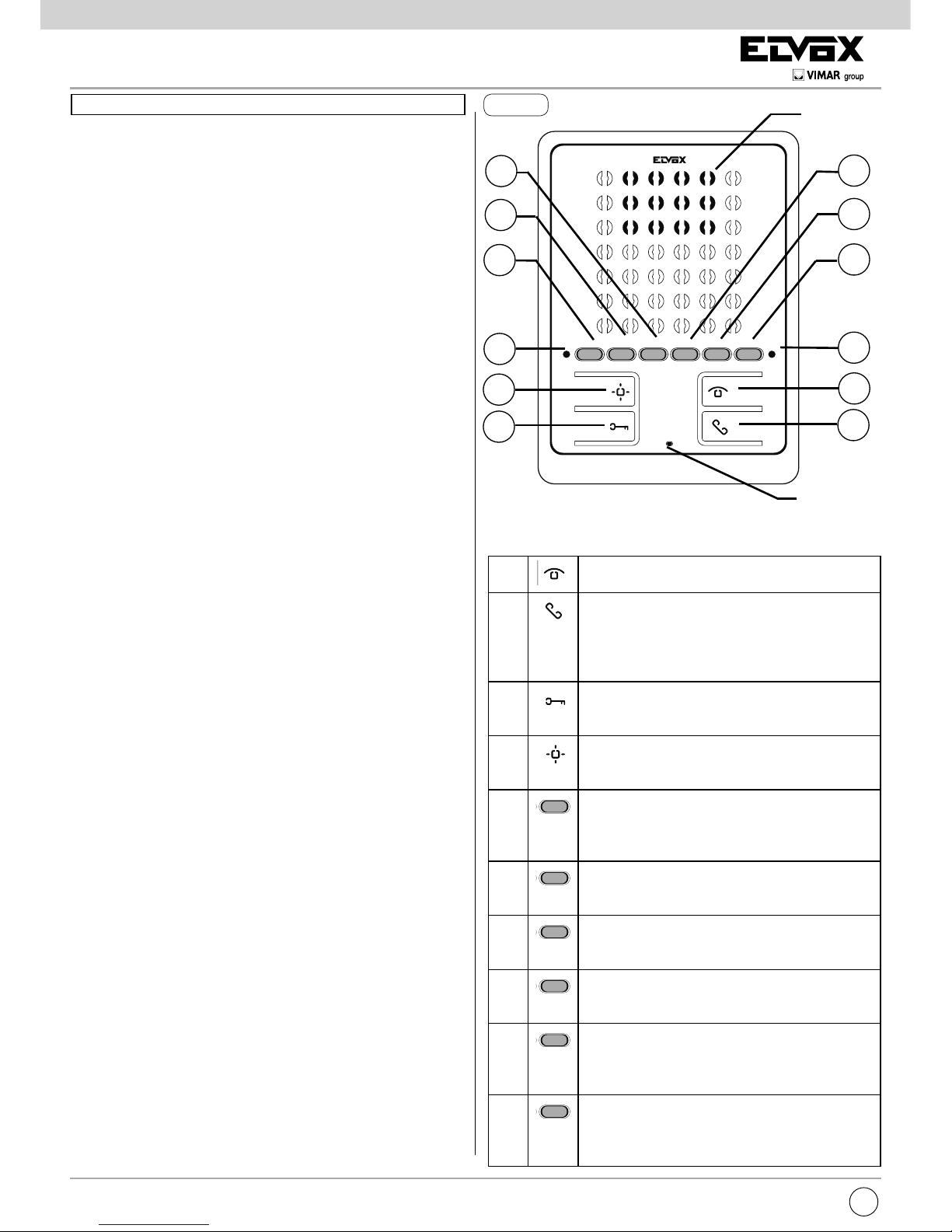
A
Autoaccensione: per l’autoinserimento del
citofono. (Di default verso la targa Master).
B
Parla/Ascolta: Attiva/disattiva la comunicazi-
one. (Di default con modalità di funzionamento
“mani libere”: dopo una chiamata o l’autoinserimento premere per attivare la conversazione,
ripremere per terminarla).
C
Serratura: comando per l’apertura serratura.
(programmazione modicabile con programmatore).
D
Ausiliario 1 (Luce scale): Per servizio ausiliario.
(Di default attiva l’attuatore 1 del relè 69RH o
69PH)
E1
Pulsante 1: Pulsante programmabile per at-
tivazione servizio ausiliario o chiamata intercomunicante. (Di default attiva l’attuatore 2 del
relè 69RH o 69PH)
E2
Pulsante 2: Pulsante programmabile per at-
tivazione servizio ausiliario o chiamata intercomunicante.
E3
Pulsante 3: Pulsante programmabile per at-
tivazione servizio ausiliario o chiamata intercomunicante.
E4
Pulsante 4: Pulsante programmabile per at-
tivazione servizio ausiliario o chiamata intercomunicante.
E5
Pulsante 5: Pulsante programmabile per at-
tivazione servizio ausiliario o chiamata intercomunicante. (Di default attiva la funzione F1
della targa)
E6
Pulsante 6: Pulsante programmabile per at-
tivazione servizio ausiliario o chiamata intercomunicante. (Di default attiva la funzione F2
della targa)
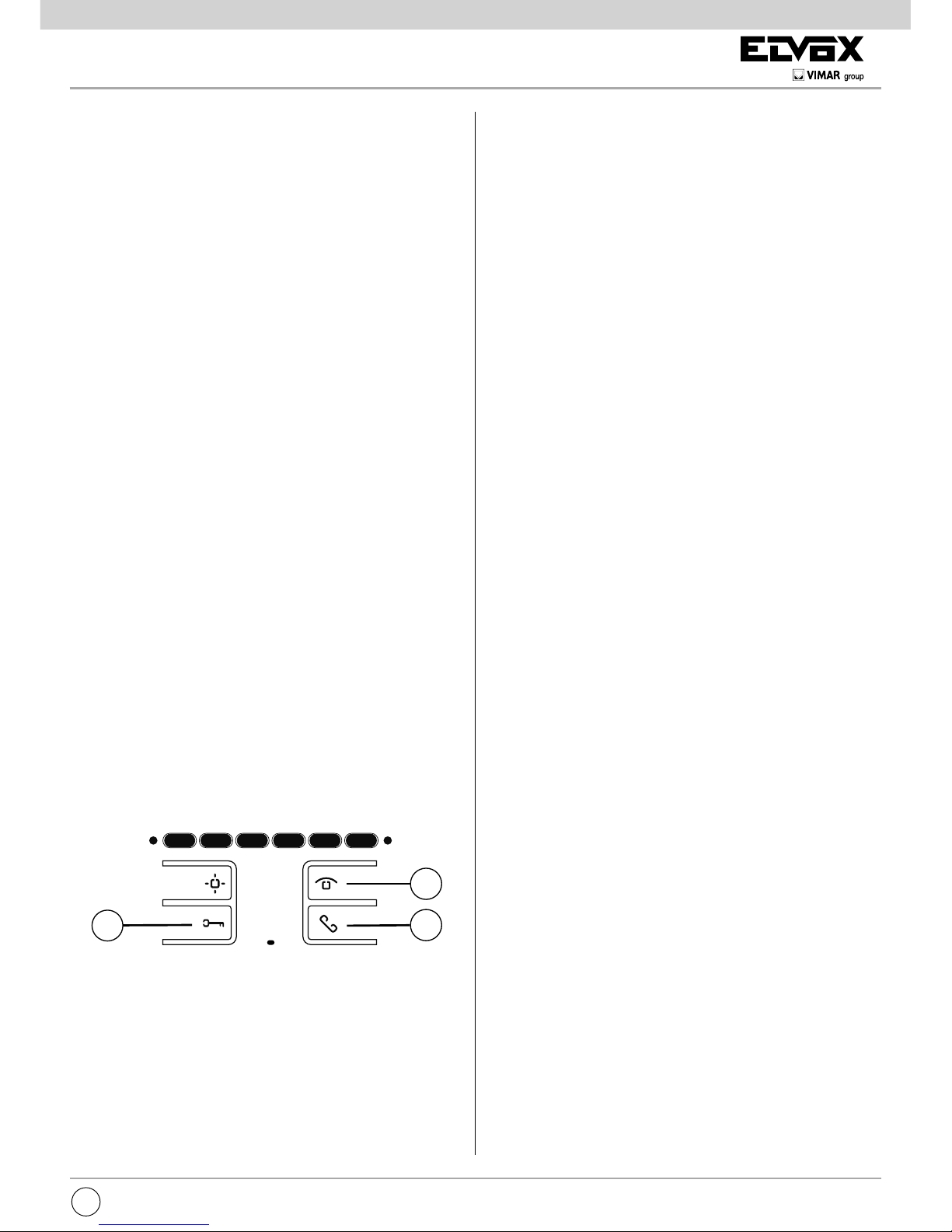
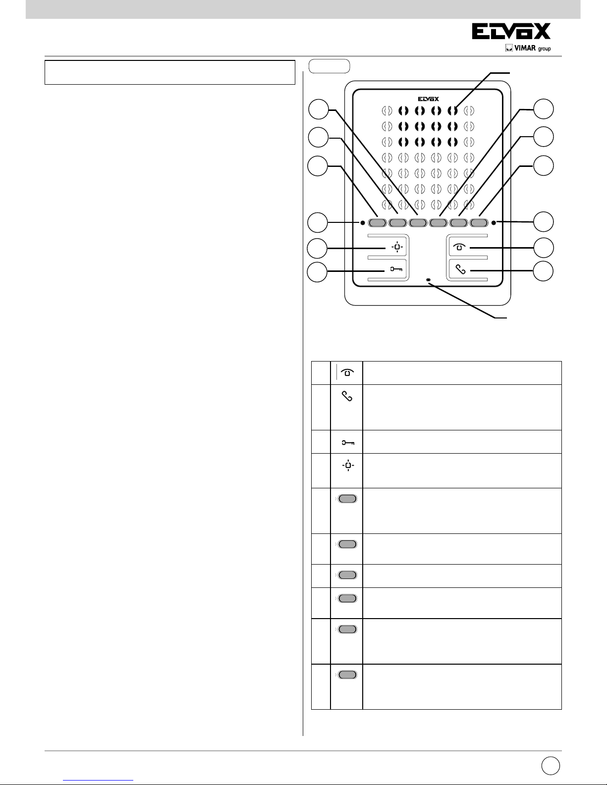
Fig. 1
Microfono
Altoparlante
E5
E4
F
E6
A
B
E2
E3
G
E1
D
C
Pulsanti:
Il manuale istruzioni è scaricabile dal sito www.vimar.com
Page 3
3
6900
IT
Segnalazione dei LED:
F Led
rosso
in funzionamento normale:
- Luce lampeggiante: segnala che il citofono
sta ricevendo una chiamata (da targa esterna
o da apparecchio intercomunicante).
- Lucessa: suoneria esclusa.
- Lucessaconfonicaattiva: segnala che si
è in conversazione (in modalità di funzionamento “mani libere”).
- Luce ssa con lampeggio ogni 10s: a
suoneria esclusa se sono state inviate chiamate dalla targa, il LED lampeggia con
un numero pari alle chiamate ricevute dalla
targa (rimangono memorizzati no a 4 chiamate). Il reset della memorizzazione dei
lampeggi avviene al ripristino del volume
della suoneria.
in funzionamento programmazione:
- Luce lampeggiante: segnala che si è in
stato di programmazione
- Lucessa: segnala che siamo in stato di
programmazione e che la comunicazione è
attiva verso la targa.
G Led
verde
in funzionamento normale:
- Lucessa: segnalazione di porta aperta se
almeno in una targa è stato installato il sensore e collegato tra i morsetti PA e M.
in funzionamento regolazione:
- Luce lampeggiante: segnala che il citofono
è in fase di regolazione del volume della
suoneria o scelta della melodia.
- Lucelampeggianteconfonicaattiva: seg-
nala che si è in fase di regolazione del volume di conversazione.
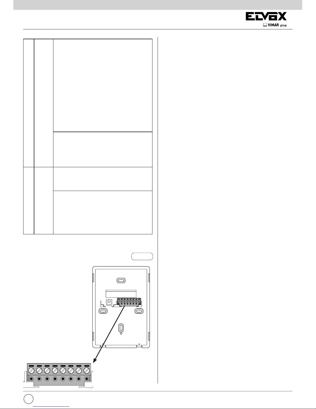
Morsetti:
1,2 Due coppie di morsetti
per Bus Due Fili
4 Riferimento massa.
5 Collegamento suone-
ria supplementare
(Riferimento positivo
12V).
6S Collegamento suone-
ria supplementare
(ripetizione suoneria).
6P Ingresso fuoriporta
(con riferimento al
morsetto 4).
6P6S542121
Fig. 2
Funzionamento
Attenzione: Per il funzionamento del citofono è necessario che sia
stata effettuata la programmazione dell’identicativo ID. Per vericare, premere un tasto del citofono (qualsiasi tasto tranne parla/ascolta) : Se al citofono è stato assegnato un ID, premendo un pulsante
verrà emesso un “bip”, se non è stato assegnato nessun ID o è stato
cancellato, emetterà un triplo “bip”.
Modalità di Funzionamento “mani libere” (default)
All’arrivo di una chiamata esterna o intercomunicante si deve
premere e rilasciare solo una volta il tasto B (parla/ascolta) per attivare la comunicazione. Premendo nuovamente il tasto B si termina
la comunicazione.
Modalità di Funzionamento “parla ascolta ”
All’arrivo di una chiamata esterna o intercomunicante si deve
premere e mantenere premuto il tasto B (parla/ascolta) per attivare
la comunicazione. La comunicazione termina automaticamente con
un ritardo di 5s dal rilascio del pulsante B.
Tempidifunzionamento
Il tempo di risposta e di conversazione dipendono dalla congurazione dei relativi parametri della targa (per modicare questi tempi fare
riferimento alle istruzioni dell’unità elettronica della targa).
- Tempo di risposta (per chiamata da targa): Valore default 30s
(Valore minimo 1s, valore massimo 255s)
- Tempo di risposta (per chiamata intercomunicante): 30s (Valore
sso)
- Tempo di conversazione (per chiamata da targa): Valore default
120s
(Valore minimo 10s, valore massimo 2550s)
- Tempo di conversazione (per chiamata intercomunicante): Valore
default 5 minuti (Modicabile in tempo illimitato).
Risposta ad una chiamata
Rispostaadunachiamatainmodalitàdifunzionamento“mani
libere”
All’arrivo di una chiamata da targa esterna o da apparecchio intercomunicante, si può rispondere durante o al termine del ciclo di suoneria. Per rispondere si deve premere brevemente e rilasciare il tasto B
(parla/ascolta). Il LED rosso segnala che il citofono è in comunicazione. Per terminare la comunicazione premere nuovamente il tasto B
(il led rosso si spegne).
Rispostaadunachiamatainmodalitàdifunzionamento“parla
ascolta”
All’arrivo di una chiamata da targa esterna o da apparecchio intercomunicante, si può rispondere durante o al termine del ciclo di
suoneria. Per rispondere si deve premere il tasto B (parla/ascolta)
e mantenerlo premuto per tutta la comunicazione. Per terminare la
comunicazione rilasciare il tasto B (parla/ascolta), dopo 5s la comunicazione si interrompe.
Rispostaadunachiamatainmodalitàdifunzionamento“mani
libere”nellafunzione“rispostaautomatica”
La funzione “risposta automatica” è disponibile solo in modalità di
funzionamento “mani libere”.
All’arrivo di una chiamata, il citofono al termine del ciclo di suoneria
attiva la comunicazione automaticamente, segnalata dall’accensione
del Led rosso a luce ssa. La comunicazione si disattiva automaticamente dopo il il tempo di conversazione previsto.
Page 4
4
6900
IT
Ricevereunachiamatafuoriporta
Il citofono può essere chiamato da un pulsante fuoriporta, se
collegato ai morsetti 4 e 6P direttamente o mediante interfaccia Art. 6120 (vedi varianti di collegamento). Premendo il
pulsante fuoriporta il citofono suona con un tono differente da
quello ottenuto con la chiamata da targa esterna o intercomunicante, la durata del ciclo di suoneria dipende dal tempo di
pressione del pulsante per un tempo massimo di 10s.
Inviare una chiamata intercomunicante
Per inviare una chiamata verso un’altro interno, è necessario
sia stato programmato uno o più pulsanti (vedi paragrafo “Programmazione dei pulsanti”).
Per chiamare, premere il pulsante programmato e riferito all’interno da chiamare. Durante la chiamata il citofono emette un
tono in modo da avvertire che la chiamata è in atto.
Quando l’interno chiamato risponde, automaticamente si at-
tiva la comunicazione (e si accende il led rosso a luce ssa).
Per terminare la conversazione premere il tasto B.
Nel caso si voglia chiudere la chiamata prima che venga risposto, premere comunque il tasto B.
La durata massima in conversazione è pari a 5 minuti.
Se il citofono è occupato in altra comunicazione nel citofono
chiamante si sentirà un tono che avverte che l’utente chiamato
è occupato.
Comando serratura
Premendo il pulsante serratura, si invia il comando di apertura
serratura alla targa (di default l’ultima targa chiamante).
Autoaccensione
- Autoaccensione con tasto dedicato (tasto A):
per fare l’autoaccensione e comunicare con la targa master,
fare una breve pressione sul tasto A. Per chiudere la comunicazione premere il tasto B.
- Autoaccensione con tasto programmato verso targa
specica:
per fare l’autoaccensione e comunicare con una targa spe-
cica, fare una breve pressione sul tasto che è stato programmato per chiamare la targa specica. Per terminare la
chiamata premere il tasto B.
Chiamata a un centralino portineria
Per effettuare una chiamata ad un centralino portineria (se
presente nell’impianto): fare una breve pressione sul tasto B,
il led verde si accenderà con luce lampeggiante per qualche
secondo, in questa fase per inviare la chiamata premere il
tasto C (serratura).
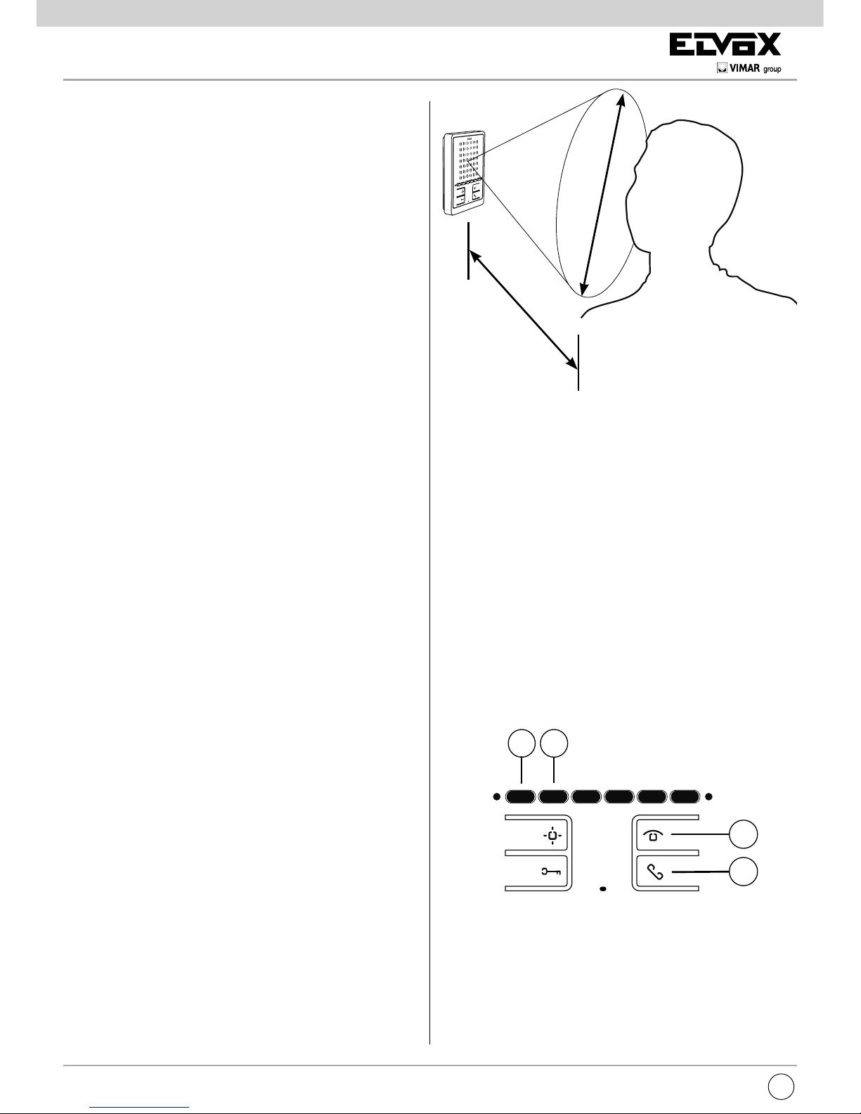
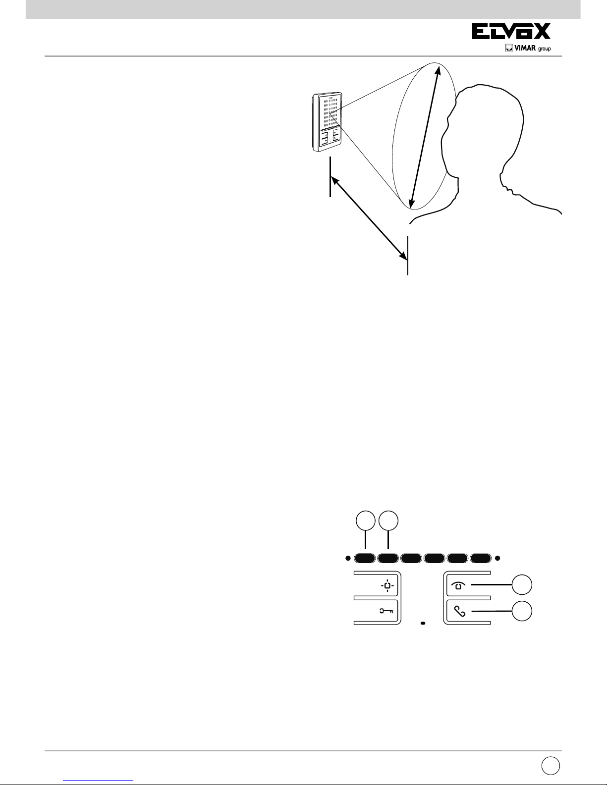
Funzione audiolesi (solo per Art. 6901/D)
L’Art. 6901/D è dotato di una bobina interna che permette l’utilizzo anche a portatori di protesi acustica. Per questo tipo di
funzionamento, è necessario commutare l’apparecchio acustico in posizione “T”.
Per una corretta ricezione del suono si consiglia che l’utilizzatore si posizioni frontalmente al citofono, in modo che l’apparecchio acustico si trovi nell’area del campo magnetico creato
dal citofono, come in gura.
Nota: l’eventuale presenza di oggetti metallici o apparecchi
elettronici, può compromettere la qualità del suono percepito
sull’apparecchio acustico.
30÷40 cm
30÷40 cm
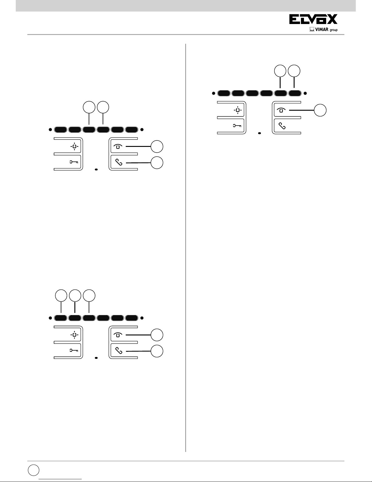
Congurazioni
Disabilita/Abilita modalità di comunicazione “mani
libere”
Il citofono 6901 è programmato di fabbrica in modalità di comunicazione a “MANI LIBERE”. Per disabilitare o riabilitare
questa funzione, seguire la procedura descritta.
Da citofono in stand-by:
1) Premere il pulsante A no all’accensione del led verde
lampeggiante, il citofono emetterà anche un tono.
2) Premere e mantenere premuti i pulsanti E1 e E2 contem-
poraneamente no a che led rosso inizia a lampeggiare.
3) Durante il lampeggio di entrambi i led, premere il pulsante
B (parla/ascolta) per confermare la modica.
Il led ROSSO si spegne appena premuto il pulsante B, il led
verde lampeggia per qualche secondo ed allo spegnimento
il citofono emette un tono.
Attenzione: Questa procedura è valida sia per abilitare che
disabilitare, una volta abilita e la volta successiva disabilita.
A
B
E2E1
Risposta automatica
E’ possibile congurare il citofono per attivarsi AUTOMATICAMENTE all’arrivo di una chiamata.
Per abilitare questa funzione, seguire la procedura descritta.
Da citofono spento:
1) Premere il pulsante A no all’accensione del led verde
lampeggiante, il citofono emetterà anche un tono.
Page 5
5
6900
IT
2) Premere e mantenere premuti i pulsanti E3 e E4 contem-
poraneamente no a che led rosso inizia a lampeggiare.
3) durante il lampeggio di entrambi i led, premere il pulsante B
(parla/ascolta) per confermare la modica.
Il led rosso si spegne appena premuto il pulsante B, il led
verde lampeggia per qualche secondo ed allo spegnimento
il citofono emette un tono.
Attenzione: Questa procedura è valida sia per abilitare che
disabilitare, una volta abilita e la volta successiva disabilita.
A
B
E3
E4
Scelta delle melodie di chiamata
Le melodie sono selezionabili e regolabili. Sono inoltre distinguibili tra chiamate esterne, intercomunicanti e fuoriporta (nel
caso descritto sotto). La regolazione delle melodie viene fatta
con citofono in stand-by.
Il pulsante per entrare in programmazione è il tasto A.
Il tasto E1 permette di selezionare la melodia per CHIAMATA
DA TARGA.
Il tasto E2 permette di selezionare la melodia per CHIAMATA
INTERCOMUNICANTE.
Il tasto E3 permette di selezionare la melodia per CHIAMATA
FUORIPORTA AUDIO (esclusivamente utilizzando pulsante di
chiamata da pianerottolo 20577 o 14577 Vimar).
A
B
E2
E3
E1
Congurazione:
1) Premere il tasto A e mantenere premuto no a quando il led
verde inizia a lampeggiare confermato anche da un “Bip”.
2) premere e mantenere premuto il tasto riferito alla suoneria
da scegliere (tasto E1/tasto E2/tasto E3) no a quando si
inizia a sentire la melodia sul citofono.
3) premere ripetutamente il tasto (tasto E1/tasto E2/tasto E3)
per selezionare il tipo di melodia desiderata.
4) Scelta la suoneria desiderata, per memorizzare premere il
tasto A o non toccare nessun tasto per 5s. Terminata la
congurazione il led verde lampeggiante si spegne.
Regolazione del volume della suoneria
Il pulsante per entrare in regolazione è il tasto A.
Il tasto E5 permette di diminuire il volume della melodia.
Il tasto E6 permette di aumentare il volume della melodia.
A
E5
E6
Congurazione:
1) Premere il tasto A e mantenere premuto no a quando il led
verde inizia a lampeggiare confermato da un “Bip”.
2) Premere il tasto E5 o E6 in funzione dell’operazione che vo-
glio eseguire (diminuire o aumentare il volume della suoneria).
3) Selezionato il volume desiderato, per memorizzare premere
il tasto A o non toccare nessun tasto per 5s. Terminata
la congurazione il led verde lampeggiante si spegne e si
sente un “bip”.
Esclusione della suoneria (Funzione utente assente)
Con la stessa procedura descritta sopra per la regolazione del
volume, premendo più volte il tasto E5 si arriva a punto in cui
la suoneria viene disattivata. Lo stato di “Suoneria esclusa”
viene segnalato dall’accensione del led rosso a luce ssa.
Se con suoneria esclusa il citofono riceve una chiamata da
targa, il led rosso lo segnala con un lampeggio per ogni chiamata a cui non è stato risposto, per un massimo di 4 chiamate
(i lampeggi vengono segnalati ogni 10s). Al ripristino almeno
del livello minimo del volume suoneria, viene resettata questa
segnalazione.
Regolazione volume di conversazione (da targa
versoilcitofono)
La regolazione del volume viene fatta durante la conversazione.
Il pulsante per entrare in regolazione è il tasto A.
Il tasto E5 permette di diminuire il volume di conversazione.
Il tasto E6 permette di aumentare il volume di conversazione.
Congurazione:
1) Premere il pulsante A e mantenere premuto no a quando
il Led verde si accende a luce lampeggiante (tutti e due i
led sono accesi).
2) Premere il tasto E5 o E6 in funzione dell’operazione che
voglio eseguire (diminuire o aumentare il volume di conversazione).
3) Selezionato il volume desiderato, per memorizzare premere
il tasto A o non toccare nessun tasto per 5s. Terminata
la congurazione il led verde lampeggiante si spegne e si
sente un “bip”.
Page 6

6
6900
IT
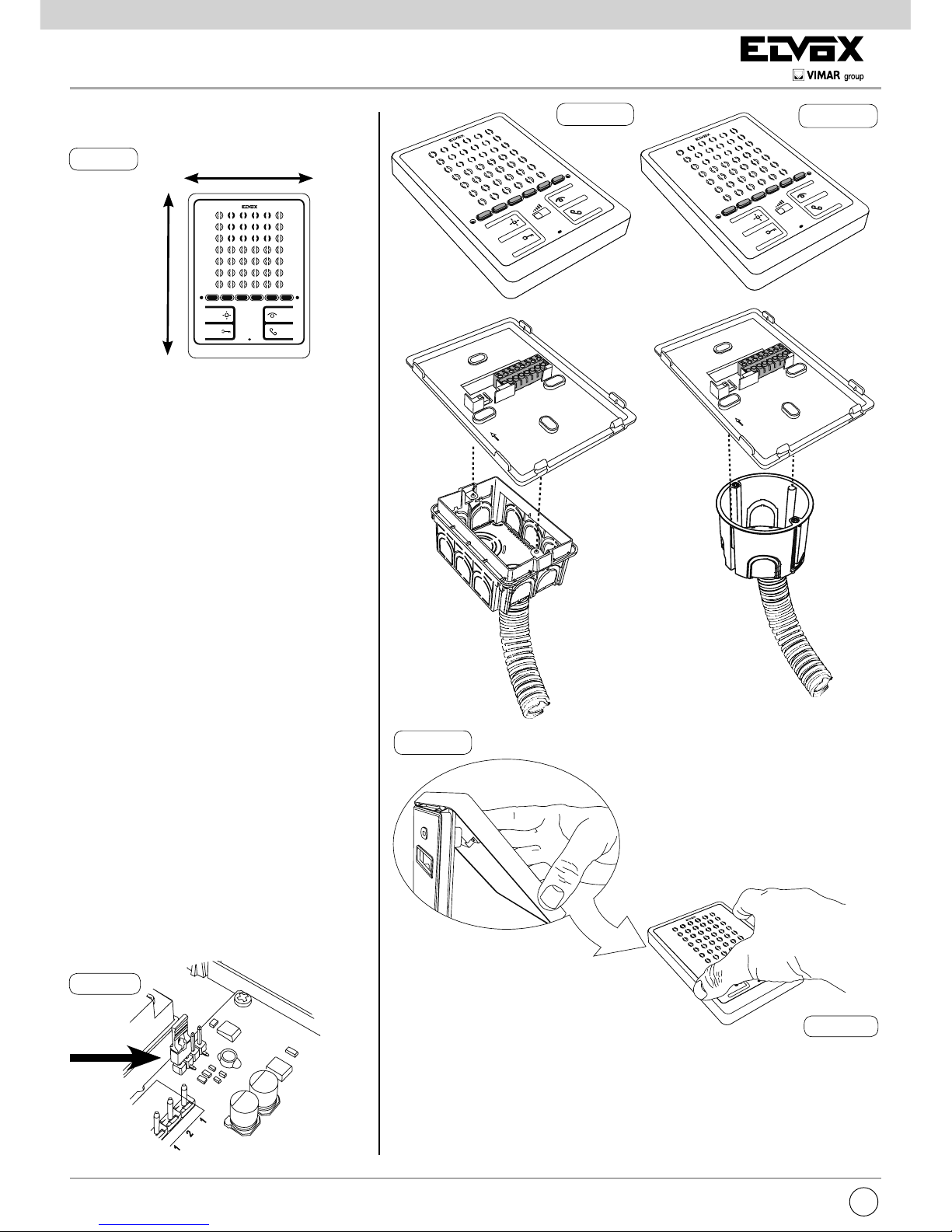
Installazione
Terminazione Bus per stabilizzazione del segnale video
All’interno del citofono è presente un “connettore di terminazione BUS” (A-B-C) per la stabilizzazione del segnale video.
A seconda della congurazione di collegamento (citofoni/videocitofoni collegati in serie
o derivati ad un distributore) settare in ponticello sul connettore ABC come descritto nella
nota “Terminazione bus per impianti DUE FILI
ELVOX” riportata in seguito, nella sezione
schemi di collegamento.
Fig. 6
Fig. 3
Dimensioni:
102 mm
142 mm
Profondità: 23 mm
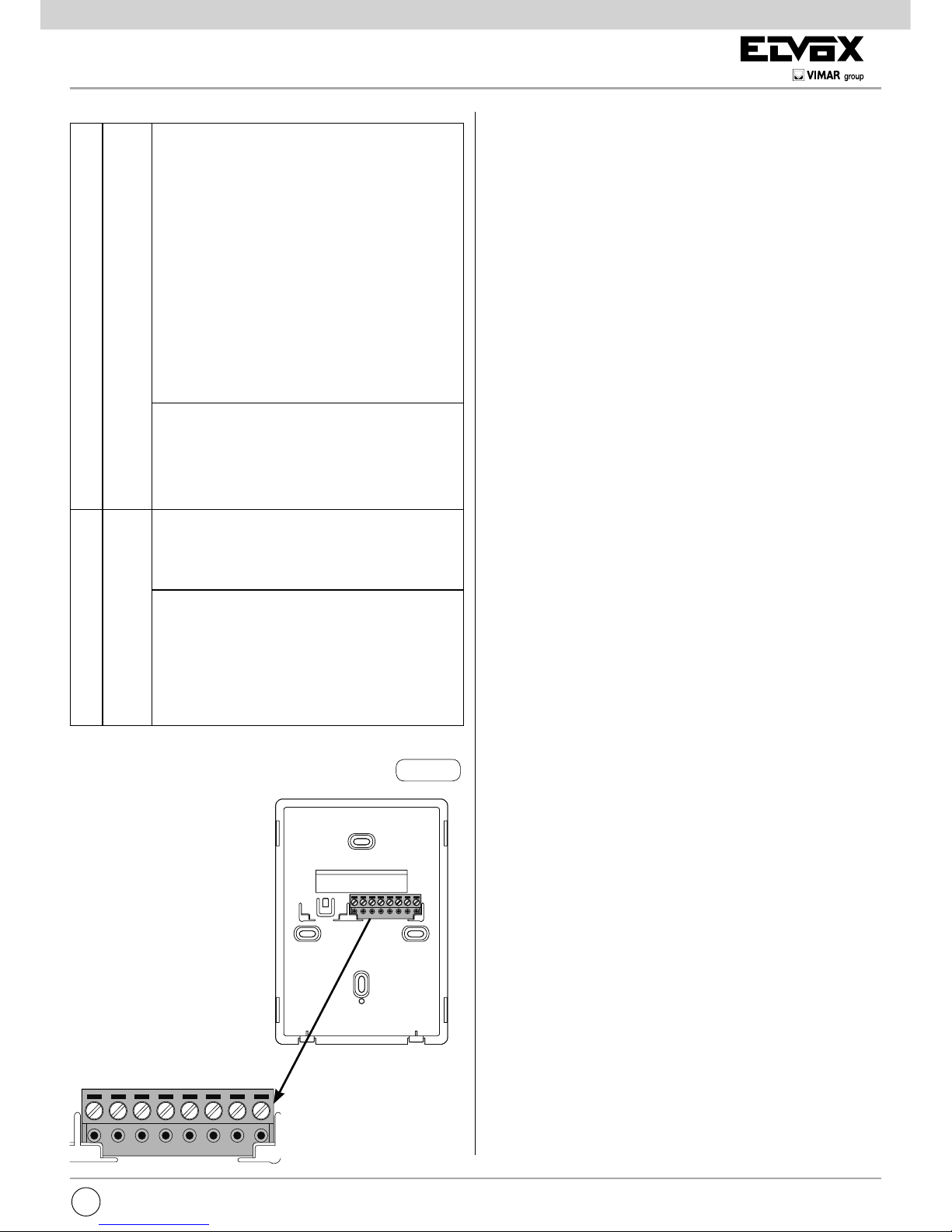
Procedura per l’installazione a parete:
- Installare il citofono lontano da fonti lu mino se e di calore.
- Fissare il fondo del citofono alla scatola verticale da incasso rettangolare o rotonda con
le relative viti fornite in dotazione (Fig. 4A,
4B), oppure ssare alla parete mediante due
tasselli.
- Si consiglia di installare il citofono ad una altezza di 1,40m dal pavimento al bordo inferiore.
- Eseguire i collegamenti alla morsettiera
(vedi schemi di collegamento).
- Chiudere il citofono alloggiando il coperchio,
prima nella parte superiore e poi facendo
una leggera pressione sulla parte inferiore,
no all’aggancio al fondo (Fig. 5A, 5B).
- Per riaprire il citofono sollevare il coperchio
facendo leva con le dita sul lato inferiore.
Fig. 4A
Fig. 5a
Fig. 5b
Fig. 4B
Page 7
7
6900
IT
4) Premere e mantenere premuti i tasti A e C no al suono di
una “nota” da parte del citofono che si sta programmando
e l’accensione del led ROSSO con luce ssa.
5) Rilasciare i tasti A e C
Attenzione: sono disponibili 5s per premere i tasti A e C
(come indicato al punto 4). Se trascorrono i 5s senza premere
i tasti A e C, deve essere ripetuta la procedura dei punti 1,2,3.
6) A questo punto, si attiva la comunicazione tra citofono e
targa e sono a disposizione 25s per effettuare l’associazione del codice ID dalla targa esterna:
- nel caso di targa alfanumerica, digitare il codice ID (lo
stesso codice ID primario assegnato al citofono capogruppo) e confermare con il tasto “campanella”.
- nel caso di targa a pulsanti, premere il pulsante dal quale
si desidera effettuare la chiamata al citofono (lo stesso
pulsante con cui è stato programmato il citofono capogruppo).
Attenzione: Se trascorrono i 25s senza aver portato a termine la procedura descritta, deve essere ripetuta la procedura
dal punto 1.
Attenzione: Nella programmazione del identicativo ID pri-
mario e secondario i citofoni in programmazione acquisiscono
automaticamente un codice che dipende dall’associazione al
pulsante o codice di chiamata della targa esterna. La corrispondenza tra il codici ID primari e i relativi ID secondari è
indicata nella tabella riportata in seguito.
Esempio: Nel caso venga dato l’identicativo ID = 8 ad un
secondo citofono, con la procedura di attribuzione dell’identificativo automatico al secondo citofono, prenderà automatica-
mente l’ID = 72 (vedi tabella).
Quando viene inviata una chiamata all’ID = 8 suoneranno en-
trambi i citofoni e si potrà rispondere da entrambi. Se invece
digito 72 che corrisponde all’identicativo ID assegnato automaticamente dalla procedura, suona e posso rispondere solo
dal citofono su cui è stata fatta la procedura di assegnazione
dell’ID secondario.
Programmazioni manuali
Le programmazioni base del citofono sono le seguenti:
- Programmazionedell’identicativoID, da effettuare sul
citofono che riceve la chiamata singolarmente o sul primo
citofono di un gruppo di citofoni con chiamata contemporanea (citofono capogruppo).
- Programmazionedell’identicativoIDsecondario , da
effettuare per i citofoni associati ad un video(citofono) capogruppo.
- Programmazione dei pulsanti programmabili o la modica
della impostazione di default di pulsanti supplementari, per
servizi ausiliari o chiamate intercomunicanti.
Programmazionedell’identicativoID
Per programmare l’identicativo ID procedere come segue:
1) Premere il tasto B e mantenere premuto.
2) Premere anche il tasto A e mantenere premuti i due tasti.
3) Quando il led rosso lampeggia rilasciare i tasti.
4) Premere il tasto C e tenerlo premuto no al suono di una
“nota” da parte del citofono che si sta programmando e l’ac-
censione del led rosso con luce ssa.
5) Rilasciare il tasto C.
Attenzione: sono disponibili 5s per premere il tasto C (come
indicato al punto 4). Se trascorrono i 5s senza premere il tasto
C, deve essere ripetuta la procedura dei punti 1,2,3.
6) A questo punto, si attiva la comunicazione tra citofono e
targa e sono a disposizione 25s per effettuare l’associazione del codice ID dalla targa esterna:
- nel caso di targa alfanumerica, digitare il codice ID prima-
rio e confermare con il tasto “campanella”.
- nel caso di targa a pulsanti, premere il pulsante dal quale
si desidera effettuare la chiamata al citofono.
Attenzione: Se trascorrono i 25s senza aver portato a termine
la procedura descritta, deve essere ripetuta la procedura dal
punto 1.
Attenzione: Se nell’impianto esiste già un citofono/videoci-
tofono con lo stesso codice identicativo associato, la targa
emette un segnale sonoro basso ed è necessario ripetere l’operazione dall’inizio per assegnare un codice diverso.
A
B
C
Programmazionedell’identicativoIDSecondario
Per programmare l’identicativo ID secondario procedere
come segue:
1) Premere il tasto B e mantenere premuto.
2) Premere anche il tasto A e mantenere premuti i due tasti.
3) Quando il led ROSSO lampeggia rilasciare i tasti.
Page 8

8
6900
IT
Programmazione dei pulsanti per chiamate intercomunicanti
Per programmare i pulsanti procedere come segue:
1) Premere il pulsante “parla/ascolta” o sganciare la cornetta
(a seconda del modello installato)” delcitofonodaCHIA-
MARE.
2) Premere il tasto B del citofonodaprogrammare(chia-
mante) e mantenere premuto.
3) Premere anche il tasto A e mantenere premuti i due tasti.
4) Attendere che il led ROSSO lampeggi.
5) Rilasciare i pulsanti A e B.
6) Premere e tenere premuto il pulsante da programmare (per
esempio E1, E2, E3, E4, E5, E6).
7) Attendere che il citofono emetta un suono.
8) Rilasciare il pulsante da programmare del citofonochi-
amante.
9) Premere nelcitofonodachiamare un pulsante (serratura
/F1/F2).
10) Una “nota” sul citofono(chiamante)inprogrammazione
conferma la memorizzazione.
Attenzione: Con questa procedura si possono riprogrammare
manualmente i pulsanti ad esclusione dei tasti parla/ascolta
(non programmabile) e dei tasti serratura e autoaccensione
per i quali è necessario il programmatore 950C o il software
SaveProg).
Programmazione del pulsante autoinserimento /
autoaccensioneversotargaspecica
(funzionediversadaautoaccensioneabilitatadapulsante“A”)
1) Premere il pulsante B e mantenere premuto.
2) Premere anche il pulsante A e mantenere entrambi premuti.
3) Attendere che il led ROSSO lampeggi.
4) Rilasciare i pulsanti A e B.
5) Premere e tenere premuto il pulsante che si vuole programmare (esclusi parla/ascolta e serratura e autoaccensione).
6) Attendere che il citofono emetta un tono.
7) Rilasciare il pulsante.
8) Nelle targhe a pulsanti si deve premere il tasto riferito al
videocitofono su cui sto memorizzando il pulsante.
Nelle targhe alfanumeriche, digitare il numero dell’ID riferito
al videocitofono su cui sto memorizzando il pulsante e confermare con il pulsante campana sulla targa.
9) Il termine della procedura sopra descritta, viene emesso un
tono acuto sul citofono, mentre dalla targa viene inviata una
chiamata al citofono su cui è stata fatta la programmazione.
Riprogrammazionedelvaloredidefaultsingolarmente per ogni pulsante
1) Premere il pulsante B e mantenere premuto.
2) Premere anche il pulsante A e mantenere entrambi premuti.
3) Attendere che il led rosso lampeggi.
4) Rilasciare i pulsanti A e B.
5) Premere e tenere premuto il pulsante che si vuole riportare
a valore di default (non valido per i pulsanti Autoaccensione
e Serratura).
6) Attendere che il citofono emetta un tono.
7) Lasciare il pulsante.
8) Ripremere il pulsante, che ora è riportato a valore di default.
Tabella codici ID primari e rispettivi secondari:
ID
Primario
ID Secondario
1 2 3
1 51 52 53
2 54 55 56
3 57 58 59
4 60 61 62
5 63 64 65
6 66 67 68
7 69 70 71
8 72 73 74
9 75 76 77
10 78 79 80
11 81 82 83
12 84 85 86
13 87 88 89
14 90 91 92
15 93 94 95
16 96 97 98
17 99 100 101
18 102 103 104
19 105 106 107
20 108 109 110
21 111 112 113
22 114 115 116
23 117 118 119
24 120 121 122
25 123 124 125
ID
Primario
ID Secondario
1 2 3
26 126 127 128
27 129 130 131
28 132 133 134
29 135 136 137
30 138 139 140
31 141 142 143
32 144 145 146
33 147 148 149
34 150 151 152
35 153 154 155
36 156 157 158
37 159 160 161
38 162 163 164
39 165 166 167
40 168 169 170
41 171 172 173
42 174 175 176
43 177 178 179
44 180 181 182
45 183 184 185
46 186 187 188
47 189 190 191
48 192 193 194
49 195 196 197
50 198 199 200
Attenzione: Cancellazione da Gruppo: per cancellare l’appartenenza da un Gruppo, deve essere usata la procedura
di cancellazione delle programmazioni descritta nel paragrafo
“Cancellazione delle programmazioni” (cancellazione di tutte
le programmazioni eseguite).
Programmazione dei pulsanti
Attenzione: senza programmatore 950C o Software Save-
Prog, è possibile assegnare solo le funzioni di intercomuni-
canti, autoinserimento targa specica, riportare al valore di
default i pulsanti che sono stati programmati dall’installatore,
cancellazione di tutte le programmazioni effettuate.
A
B
C
E2
E3
E1 E5
E6
E4
D
Page 9
9
6900
IT
Cancellazione di tutte le programmazioni contemporaneamente
1) Premere il tasto B e mantenere premuto.
2) Premere anche il tasto A e mantenerli premuti.
3) Attendere che il led ROSSO lampeggi.
4) Rilasciare i tasti A e B.
5) Premere nuovamente e mantenere premuto il tasto A.
6) Quando il citofono emette una “nota”, durante il suono, rilas-
ciare il tasto A e premere brevemente il tasto C.
A questo punto le programmazioni del citofono sono cancellate. Per prova dell’avvenuta cancellazione della programmazioni, premere il pulsante C, il citofono deve emettere un
triplo “Bip”.
Programmazioniecongurazioni conprogrammatore 950C
La programmazione del citofono, può essere fatta mediante
il programmatore Art. 950C. É necessario collegare il pro-
grammatore ad una targa ed entrare nella congurazione
del dispositivo. Con il programmatore è possibile modicare
le programmazioni dei pulsanti (ad eccezione del pulsante
parla/ascolta), creare i Gruppi, selezionare i tipi di melodia e
regolare volumi di suoneria e di conversazione e inoltre abilitare/disabilitare funzioni. Per l’uso del programmatore, fare
riferimento alle relative istruzioni.
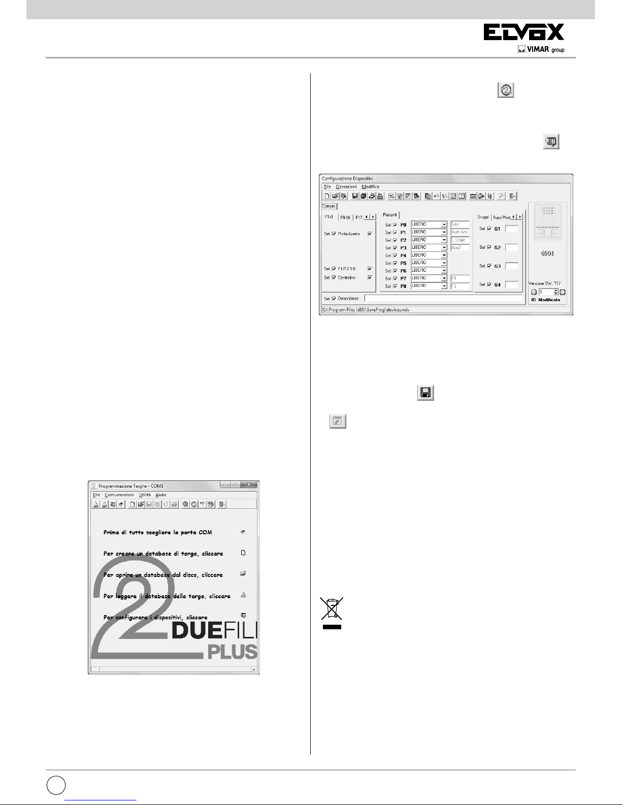
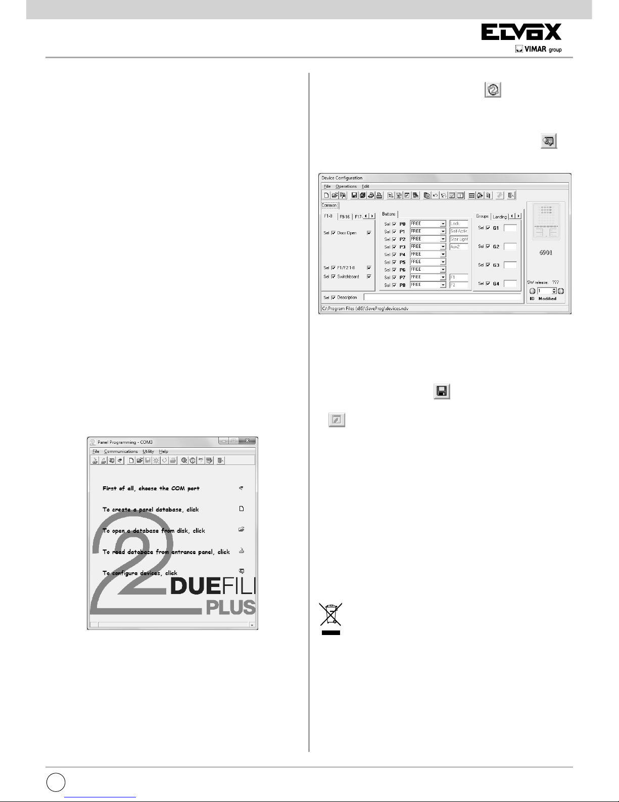
ProgrammazioneconSoftwareSAVEPROG
SaveProg è un software per PC fornito in dotazione alle interfacce Art. 692I e 692I/U. Queste interfacce permettono il
collegamento del PC ad una targa o ad altro dispositivo predisposto, 692I tramite una porta RS232 mentre 692I/U tramite
connessione USB.
Dopo aver collegato l’interfaccia e installato SaveProg,
aprendo il programma, appare la nestra seguente.
A questo si può procedere alla programmazione in due diverse due modalità:
1) con 950C virtuale: cliccando sull’icona
si apre un’immagine interattiva del programmatore 950C che permette
effettuare le programmazioni simulando l’utilizzo del programmatore 950C.
2) con le nestre di SaveProg: cliccando sull’icona
si
apre la nestra di “Congurazionedispositivi”.
A questo punto è possibile: modicare le programmazioni
dei pulsanti (ad eccezione del pulsante parla/ascolta), creare
i Gruppi, scegliere i tipi di melodie e regolare i volumi delle
suonerie e di conversazione, abilitare e disabilitare funzioni.
Al termine delle impostazioni desiderate, si deve:
- salvare cliccando su
.
- trasferire il programma nel dispositivo cliccando sull’icona
.
A questo punto il dispositivo è stato riprogrammato.
REGOLED’INSTALLAZIONE
L’installazione deve essere effettuata con l’osservanza delle
disposizioni regolanti l’installazione del materiale elettrico in
vigore nel paese dove i prodotti sono installati.
CONFORMITA’NORMATIVA
Direttiva BT
Direttiva EMC
Norma EN 50486, EN 60118-4
INFORMAZIONEAGLIUTENTIAISENSIDELLA
DIRETTIVA2002/96(RAEE)
Al ne di evitare danni all’ambiente e alla salute umana
oltre che di incorrere in sanzioni amministrative, l’apparecchiatura che riporta questo simbolo dovrà essere smaltita
separatamente dai riuti urbani ovvero riconsegnata al distributore all’atto dell’acquisto di una nuova. La raccolta dell’apparecchiatura contrassegnata con il simbolo del bidone barrato dovrà avvenire in conformità alle istruzioni emanate dagli
enti territorialmente preposti allo smaltimento dei riuti. Per
maggiori informazioni contattare il numero verde 800-862307.
Page 10
10
6900
EN
Description
Two-channel hands-free interphone in thermoplastic material
with loudspeaker for electronic call. Equipped with four buttons
dedicated to the main video door entry system functions: door
lock release, self-start, auxiliary services (stair light), conversation. The internal audio volume and chime volume can also
be adjusted, muting with “privacy” function activated and various chimes selected. Option of setting different chimes for
calls made from different points, e.g.: outdoor entrance panel,
door call, intercommunicating call. With the chime muted, a
red LED will signal up to 4 unanswered calls by ashing a
corresponding number of times. Speakerphone system with
hands-free mode. Green LED “door open” signal. Option of
operating up to six auxiliary functions or intercommunicating
calls. Suitable for wall mounting using screws and wall plugs,
or for connection to rectangular/round junction boxes. For use
in Elvox Two-Wire systems with power supply art. 6922.
Art. 6901/D has a hearing aid function. When this function is in
use, the hearing aid must be set to the “T” position.
Before programming, read the instructions carefully so
that you are fully aware of all features, functions and performance options.
Technicalspecications
• ABS interphone
• Surface-wall mount installation: The interphone can be in-
stalled in back box model 503, round 60 or 70 mm back
boxes or directly in the wall using wall plugs. The circuit is
connected to the cover, i.e. the removable part, while the
terminal block remains xed to the base.
• Standard colour: white
• Two-wire Bus power supply
• Power consumption:
- in standby: 2 mA
- in standby with red LED lit steadily: 5 mA
- in standby with red and green LEDs lit: 7 mA
- maximum in-call current: 110 mA
- maximum conversation current for 6901: 100 mA
- maximum conversation current for 6901/D: 130 mA
• Option of installing up to 8 interphones with simultaneous
calls.
• Operating temperature: 0° to 40°C
• Electronic chime: with diversication between entrance
panel calls, intercommunicating calls and door calls. There
are 10 different chime melodies to choose from.
• Output for additional chime art. 860A or relay art. 0170/101.
• Input for door calls with different chime from entrance panel
calls.
• Dimensions: 102x142x23 mm
Fig. 1
Loudspeaker
Microphone
Buttons:
A Self-start: for interphone self-activation
(Master entrance panel by default).
B
Talk/Listen: Activates/deactivates communica-
tion (with hands-free operating mode by default:
after call or self-activation, press to begin conversation and press again to end it).
C
Lock: lock opening command (programming
can be adjusted using the programmer).
D
Auxiliary 1 (stair light): For auxiliary service
(actuator 1 of relay 69RH or 69PH activated by
default).
E1
Button 1: Programmable button for auxiliary
service activation or intercommunicating call
(actuator 2 of relay 69RH or 69PH activated by
default).
E2
Button 2: Programmable button for auxiliary
service activation or intercommunicating call
E3
Button 3: Programmable button for auxiliary
service activation or intercommunicating call
E4
Button 4: Programmable button for auxiliary
service activation or intercommunicating call
E5
Button 5: Programmable button for auxiliary
service activation or intercommunicating call
(entrance panel function F1 activated by default).
E6
Button 6: Programmable button for auxiliary
service activation or intercommunicating call
(entrance panel function F2 activated by default).
E5
E4
F
E6
A
B
E2
E3
G
E1
D
C
The instruction manual is downloadable from the site www.
vimar.com
Page 11
11
6900
EN
LED indications:
6P6S542121
Fig. 2
Operation
Important: For the interphone to work, the ID must have already been programmed. To check this, press one of the interphone buttons (any button apart from speak/listen). If an ID
has been assigned to the interphone, a beep will sound when
a button is pressed; if no ID has been assigned or it has been
deleted, a triple beep will sound.
Hands-freeoperatingmode (default)
When an outdoor or intercommunicating call is received, press
and release button B (speak/listen) just once to begin commu-
nication. Press button B again to end communication.
Speak/listen operating mode
When an outdoor or intercommunicating call is received,
press and hold button B (speak/listen) to begin communication. Communication ends automatically 5 s after button B is
released.
Operatingtimes
The answer and conversation times depend on the conguration of the corresponding entrance panel parameters (to
change these times, please refer to the electronic entrance
panel unit instructions).
- Answer time (for entrance panel call): Default value 30 s
(minimum value 1 s, maximum value 255 s)
- Answer time (for intercommunicating call): 30 s (xed value)
- Conversation time (for entrance panel call): Default value
120 s
(minimum value 10 s, maximum value 2550 s)
- Conversation time (for intercommunicating call): Default
value 5 minutes (adjustable; no time limit)
Answering a call
Answeringacallin“hands-free”mode
A call from the outdoor entrance panel or from an intercommunicating device can be answered during the chime cycle
or once it has ended. To answer, press and release button B
(speak/listen). The red LED indicates that the interphone is
in use. To end communication, press button B again (the red
LED switches off).
Answering a call in “speak/listen” mode
A call from the outdoor entrance panel or from an intercommunicating device can be answered during the chime cycle or
once it has ended. To answer, press and hold button B (speak/
listen) during the entire communication. To end communication, release button B (speak/listen); after 5 s communication
will stop.
Answeringacallin“hands-free” modewith“automatic
answer”function
The “automatic answer” function is only available in “hands-
free” mode.
On receipt of a call, the interphone starts communication automatically at the end of the chime cycle; the red LED lights
up steadily to indicate this. Communication ends automatically
after the set conversation time.
F Red
LED
during normal operation:
- Flashing light: indicates that the inter-
phone is receiving a call (from outdoor entrance panel or from intercommunicating
device).
- Steady light: chime muted.
- Steady light with active audio: indica-
tes that a conversation is in progress (in
“hands-free” operating mode).
- Steady light with ashing every 10 s:
when the chime is muted and if calls have
been made from the entrance panel, the
LED ashes a corresponding number of
times to indicate the number of call made
(up to 4 calls are logged). The log is reset
when the chime volume is restored.
during programming:
- Flashing light: indicates that programming
is underway.
- Steady light: indicates that programming
is underway and that communication with
the entrance panel is in progress.
G Green
LED
during normal operation:
- Steady light: door open indication, if the
sensor is installed in at least one entrance
panel and connecting terminals PA and M.
during adjustment:
- Flashing light: indicates that the inter-
phone chime volume is being adjusted or
the melody selected.
- Flashing light with active audio: indica-
tes that the conversation volume is being
adjusted.
Terminals:
1, 2 Two pairs of terminals
for Two-wire Bus
4 Earth reference
5 Additional chime wi-
ring (Positive 12 V re-
ference)
6S Additional chime wi-
ring (chime repetition)
6P Door call input (with re-
ference to terminal 4)
Page 12
12
6900
EN
Receiving a door call
The interphone can receive calls from a door call button, if
the latter is directly connected to terminals 4 and 6P or via
interface art. 6120 (see wiring versions).
When the door call button is pressed, the interphone emits a
different tone to the one used for outdoor entrance panel calls
or intercommunicating calls; chime cycle duration depends on
the amount of time for which the button was pressed (max.
10 s).
Making an intercommunicating call
To make a call to another indoor unit, one or more buttons
must have been programmed (see “Button programming”
section). To make the call, press the button programmed for
the relevant indoor unit. During the call, the interphone emits a
tone in order to signal that the call is being made.
When the internal unit receiving the call answers, communication begins automatically (the red LED lights up steadily).
Press button B to end the conversation.
If you want to end the call before it is answered, press B.
The maximum conversation duration is 5 minutes.
If the interphone is already engaged with another call, a tone
will be heard on the interphone making the call to indicate that
the user receiving the call is busy.
Lock command
Press the lock button to transmit a lock opening command
to the entrance panel (by default, the last entrance panel to
make a call).
Self-start
- Self-startwithdedicatedbutton(buttonA):
to use the self-start function and communicate with the master
entrance panel, press and release button A. To end communication, press button B.
- Self-start with button programmed for specied en-
trance panel:
to use the self-start function and communicate with a specic
entrance panel, press and release the button programmed to
call that entrance panel. Press button B to end the call.
Calling a porter switchboard
To call a porter switchboard (where tted): press and release
button B; the green LED will ash for a few seconds. Press
button C (lock) at this stage to make the call.
Hearingaidfunction(art.6901/Donly)
Art. 6901/D has an internal coil which allows hearing aid wearers to use the device. In this operating mode, the hearing aid
must be switched to the “T” position.
For correct chime reception, the user should stand in front of
the interphone, so that the hearing aid is within the magnetic
eld created by the interphone, as shown in the gure.
Note: any metal objects or electronic equipment nearby may
compromise the quality of the sound received by the hearing aid.
Congurations
Disabling/Enabling“hands-free”communication
Interphone 6901 is programmed by default for “HANDS-FREE”
communication.
To disable or re-enable this function, follow the procedure as
described.
When the interphone is in standby:
1) Press button A until the green LED ashes; the interphone
will also emit a tone.
2) Press and hold buttons E1 and E2 simultaneously, until the
red LED begins to ash.
3) While both LEDs are ashing, press button B (speak/listen)
to conrm the change.
The RED LED switches off as soon as button B is pressed,
while the green LED ashes for a few seconds when it switches off, the interphone emits a tone.
Important: This procedure applies for both enabling and disabling, once to enable and another time to disable.
A
B
E2E1
Automatic answer
The interphone can be congured to start AUTOMATICALLY
on receipt of a call.
To enable this function, follow the procedure as described.
While the interphone is off:
1) Press button A until the green LED ashes; the interphone
will also emit a tone.
30÷40 cm
30÷40 cm
Page 13
13
6900
EN
2) Press and hold buttons E3 and E4 simultaneously, until the
red LED begins to ash.
3) While both LEDs are ashing, press button B (speak/listen)
to conrm the change.
The red LED switches off as soon as button B is pressed,
while the green LED ashes for a few seconds when it switches off, the interphone emits a tone.
Important: This procedure applies for both enabling and disabling, once to enable and another time to disable.
A
B
E3
E4
Selecting call melodies
Melodies can be selected and adjusted. Different melodies
can also be set for outdoor, intercommunicating and door calls
(see below). Melodies are adjusted while the interphone is in
standby.
Button A is used to enter programming mode.
Button E1 selects the ENTRANCE PANEL CALL melody.
Button E2 selects the INTERCOMMUNICATING CALL melody.
Button E3 selects the AUDIO DOOR CALL melody (using only
landing call button 20577 or 14577 by Vimar).
A
B
E2
E3
E1
Conguration:
1) Press and hold button A until the green LED begins to ash;
this will also be conrmed by a beep.
2) Press and hold the button corresponding to the desired
chime (button E1/button E2/button E3) until you hear the
melody on the interphone.
3) Press the button (button E1/button E2/button E3) repeate-
dly to select the desired melody.
4) Once you have selected the desired chime, press button A
to store it or do not touch any buttons for 5 s. Once conguration is complete, the ashing green LED switches off.
Chime volume adjustment
Button A is used to enter adjustment mode.
Button E5 decreases the melody volume.
Button E6 increases the melody volume.
A
E5
E6
Conguration:
1) Press and hold button A until the green LED begins to ash;
this will be conrmed by a beep.
2) Press button E5 or E6 depending on the procedure you
want to carry out (decrease or increase the chime volume).
3) Once you have selected the desired volume, press button
A to store it or do not touch any buttons for 5 s. Once con-
guration is complete, the ashing green LED switches off
and a beep is emitted.
Mutingthechime(Userawayfunction)
Using the same procedure as described above for volume
adjustment, press button E5 several times to reach the point
at which the chime is deactivated. “Chime muted” status is
indicated by the red LED lighting up steadily.
If the interphone receives a call from the entrance panel while
the chime is muted, the red LED indicates this with one ash
for each unanswered call, for a maximum of 4 calls (these a-
shes occur every 10 s). When the chime volume is restored, at
least to its minimum level, this indication will be reset.
Adjustingtheconversationvolume(fromentrance
panel to interphone)
The volume is adjusted during conversation.
Button A is used to enter adjustment mode.
Button E5 decreases the conversation volume.
Button E6 increases the conversation volume.
Conguration:
1) Press and hold button A until the green LED begins to ash
(both LEDs are lit).
2) Press button E5 or E6 depending on the procedure you
want to carry out (decrease or increase the conversation
volume).
3) Once you have selected the desired volume, press button
A to store it or do not touch any buttons for 5 s. Once con-
guration is complete, the ashing green LED switches off
and a beep is emitted.
Page 14
14
6900
EN
Installation
Bus termination for video signal stabilisation
There is a “BUS termination connector” (A-BC) inside the interphone to stabilise the video
signal.
Depending on the wiring conguration (interphones/monitors connected in series or which
are distributor extensions), set connector ABC
to jumper, as described in note “Bus termination for ELVOX TWO-WIRE installations”
below, in the wiring diagrams section.
Fig. 6
Fig. 3
Dimensions:
Depth: 23 mm
Wall mounting procedure:
- Install the interphone away from sources of
li g ht and heat.
- Fix the base of the interphone to the rectan-
gular or round vertical back box using the
corresponding screws supplied (Fig. 4A,
4B), or x it to the wall using two wall plugs.
- We recommend installing the interphone so
that its lower edge is 1.40 m from the oor.
- Wire it to the terminal board (see wiring dia-
gram).
- Fit the interphone cover: rst position the top
part and then push the bottom part gently,
until it clicks into place (Fig. 5A, 5B).
- To reopen the interphone, lift the cover by
levering the lower edge with your ngers.
Fig. 4A
Fig. 4B
102 mm
142 mm
Fig. 5a
Fig. 5b
Page 15
15
6900
EN
5) Release buttons A and C.
Important: you will have 5 s in which to press buttons A and C
(as indicated in step 4). If button A and C is not pressed within
the 5 s, steps 1, 2 and 3 must be repeated.
6) At this point, communication between the interphone and
the entrance panel begins and you have 25 s to link the ID
code of the outdoor entrance panel:
- if using an alphanumeric entrance panel, enter the ID
code (the same primary ID code as assigned to the
group master interphone) and conrm with the “bell” button.
- if using an entrance panel with buttons, press the but-
ton you want to use for calling the interphone (the same
button with which the group master interphone was programmed).
Important: If the procedure described is not completed within
the 25 s, it must be repeated from step 1.
Important: When programming the primary and secondary
ID, the interphones undergoing programming automatically
acquire a code that depends on the association with the button
or code used to call the outdoor entrance panel. Correspondence between the primary ID and the respective secondary
ID codes is provided in the table below.
Example: If ID = 8 is given to a second interphone, the automatic second interphone identication attribution procedure
will automatically assume ID = 72 (see table).
When a call is made to ID = 8, both interphones will chime and
you will be able to answer from both. If, on the other hand, you
enter 72 (the ID automatically assigned by the procedure), a
ring tone is emitted by - and you will only be able to answer
from - the interphone for which the secondary ID assignation
procedure was carried out.
Manual programming
Basic interphone programming is as follows:
- ID programming, performed on the interphone receiving
the call separately or on the rst in a group of interphones
with simultaneous calls (master interphone for the group).
- Secondary ID programming, performed for interphones
linked to a group master interphone/monitor.
- Programming programmable buttons or changing the
default settings of additional buttons, for auxiliary services
or intercommunicating calls.
ID programming
To program the ID, proceed as follows:
1) Press and hold button B.
2) Press and hold button A at the same time.
3) Release the buttons when the red LED ashes.
4) Press and hold button C until you hear a “note” from the
interphone to conrm programming is underway; this will
be accompanied by the red LED lighting up steadily.
5) Release button C.
Important: you will have 5 s in which to press button C (as
indicated in step 4). If button C is not pressed within the 5 s,
steps 1, 2 and 3 must be repeated.
6) At this point, communication between the interphone and
the entrance panel begins and you have 25 s to link the ID
code of the outdoor entrance panel:
- if using an alphanumeric entrance panel, enter the pri-
mary ID code and conrm with the “bell” button.
- if using an entrance panel with buttons, press the button
you want to use for calling the interphone.
Important: If the procedure described is not completed within
the 25 s, it must be repeated from step 1.
Important: If the installation already contains an interphone/
monitor with the same associated identication code, the entrance panel emits a low sound signal and the process must
be repeated from the start in order to assign a different code.
A
B
C
Secondary ID programming
To program the secondary ID, proceed as follows:
1) Press and hold button B.
2) Press and hold button A at the same time.
3) Release the buttons when the RED LED ashes.
4) Press and hold buttons A and C until you hear a “note” from
the interphone to conrm programming is underway; this
will be accompanied by the RED LED lighting up steadily.
Page 16
16
6900
EN
Programming intercommunicating call buttons
To program the buttons, proceed as follows:
1) Press “speak/listen” or lift the handset (depending on the
model installed) oftheinterphoneyouwishTOCALL.
2) Press and hold button B on the interphone you wish to
program (making the call).
3) Press and hold button A at the same time.
4) Wait for the RED LED to ash.
5) Release buttons A and B.
6) Press and hold the button you wish to program (e.g. E1, E2,
E3, E4, E5, E6).
7) Wait for the interphone to emit a chime.
8) Release the button you wish to program on the interphone
making the call.
9) Press a button (lock/F1/F2) on the interphone you wish
to call.
10) A “note” on the interphone (making the call) being pro-
grammed conrms the setting has been saved.
Important: This procedure can be used to manually reprogram the buttons, with the exception of the speak/listen button
(not programmable) and the lock and self-start buttons (for
which programmer 950C or SaveProg software is required).
Programmingtheself-activation/self-startbutton
toaspecicpanel
(differentfromtheself-startfunctionenabledusingbutton
“A”)
1) Press and hold button B.
2) Press and hold button A at the same time.
3) Wait for the RED LED to ash.
4) Release buttons A and B.
5) Press and hold the button you wish to program (excluding
speak/listen, lock and self-start).
6) Wait for the interphone to emit a tone.
7) Release the button.
8) For entrance panels with buttons, press the button corresponding to the monitor on which the button is being saved.
For alphanumeric entrance panels, enter the ID number
corresponding to the monitor on which the button is being
saved, and conrm using the bell button on the entrance
panel.
9) At the end of the procedure described above, a sharp tone
will be emitted by the interphone, while the entrance panel
makes a call to the interphone on which programming has
taken place.
Reprogrammingthedefaultvalueseparatelyfor
each button
1) Press and hold button B.
2) Press and hold button A at the same time.
3) Wait for the red LED to ash.
4) Release buttons A and B.
5) Press and hold the button for which you wish to restore
the default setting (does not apply to Self-start and Lock
buttons).
6) Wait for the interphone to emit a tone.
7) Release the button.
8) Press the button again (it will now be restored to its default
value).
TableofprimaryandrespectivesecondaryIDcodes:
Primary
ID
Secondary ID
1 2 3
1 51 52 53
2 54 55 56
3 57 58 59
4 60 61 62
5 63 64 65
6 66 67 68
7 69 70 71
8 72 73 74
9 75 76 77
10 78 79 80
11 81 82 83
12 84 85 86
13 87 88 89
14 90 91 92
15 93 94 95
16 96 97 98
17 99 100 101
18 102 103 104
19 105 106 107
20 108 109 110
21 111 112 113
22 114 115 116
23 117 118 119
24 120 121 122
25 123 124 125
Primary
ID
Secondary ID
1 2 3
26 126 127 128
27 129 130 131
28 132 133 134
29 135 136 137
30 138 139 140
31 141 142 143
32 144 145 146
33 147 148 149
34 150 151 152
35 153 154 155
36 156 157 158
37 159 160 161
38 162 163 164
39 165 166 167
40 168 169 170
41 171 172 173
42 174 175 176
43 177 178 179
44 180 181 182
45 183 184 185
46 186 187 188
47 189 190 191
48 192 193 194
49 195 196 197
50 198 199 200
Important: Delete from Group: to delete from a group, the
programming deletion procedure described in the “Deleting
programming” section must be carried out (all programming
deleted).
Button programming
Important: without programmer 950C or SaveProg software,
the only functions that can be assigned are intercommunica-
ting, specic entrance panel self-activation, restoring buttons
programmed by the installer to their default settings and deleting all programming procedures performed.
A
B
C
E2
E3
E1 E5
E6
E4
D
Page 17
17
6900
EN
Deleting all programming at once
1) Press and hold button B.
2) Press and hold button A at the same time.
3) Wait for the RED LED to ash.
4) Release buttons A and B.
5) Press and hold button A again.
6) When the interphone emits a “note”, during the chime, rele-
ase button A and press and release button C.
At this point interphone programming will be deleted. To test
programming deletion, press button C; the interphone should
beep three times.
Programmingandconguringwithprogrammer 950C
Interphone programming can be carried out using programmer
art. 950C. The programmer must be connected to an entrance
panel and device conguration mode started. This programmer can be used to: change button programming (except
the speak/listen button), create groups, select melody types,
adjust the chime or conversation volume and enable or disable
functions. When using the programmer, please refer to the
corresponding instructions.
ProgrammingwithSAVEPROGsoftware
SaveProg is a software program for PCs, supplied with interfaces art. 692I and 692I/U. These interfaces enable connection
of the PC to an entrance panel or another suitable device, 692I
via an RS232 port and 692I/U via a USB connection.
Once the interface is connected and SaveProg installed, when
you open the program the following window appears.
At this point you may proceed with programming in two different ways:
1) with virtual 950C: click on the icon
to open an interactive image of the 950C programmer , allowing programming to take place by simulating programmer 950C
operation.
2) using the SaveProg windows: click on the icon
to
open the “Deviceconguration” window.
At this point you can: change button programming (except
the speak/listen button), create groups, select melody types,
adjust the chime or conversation volume and enable or disable
functions.
When the desired settings have been applied:
- save them by clicking on
;
- transfer the program to the device by clicking on the icon
.
At this point the device will have been reprogrammed.
INSTALLATIONRULES
Installation should be carried out observing current installation regulations for electrical systems in the country where the
products are installed.
CONFORMITY
BT directive
EMC directive
Standards EN 50486, EN 60118-4.
USERINFORMATIONINCOMPLIANCEWITH
EUROPEANDIRECTIVE2002/96(RAEE)
In order to avoid damage to the environment and human health as well as any administrative sanctions, any appliance marked with this symbol must be disposed of separately
from municipal waste, that is it must be reconsigned to the
dealer upon purchase of a new one. Appliances marked with
the crossed out wheelie bin symbol must be collected in accordance with the instructions issued by the local authorities
responsible for waste disposal.
Page 18

18
6900
FR
Description
Portier à vive voix à deux canaux en matière thermoplastique avec haut-parleur pour appel électronique. Doté de 4
boutons dédiées aux fonctions primaires du portier vidéo
pour ouvre-porte, allumage automatique, services auxiliaires
(éclairage escaliers), conversation. Il est également possible de régler le volume interne de la phonie, le volume de
la sonnerie et d’exclure l’activation de la fonction « privacy
», de sélectionner de différentes sonneries. Possibilité de
différencier les sonneries pour les appels depuis plusieurs
points, par exemple : plaque de rue, appel du palier, appel
intercommunicant. Avec la sonnerie exclue, une LED rouge
signalera jusqu’à 4 appels « sans réponse » par une série de
clignotements. Système à communication vocale avec mode
de communication « mains libres ” (Hands Free). Signalisation
« porte ouverte » par l’allumage d’une led verte. Possibilité de
mettre en place jusqu’à six fonctions auxiliaires ou appels in-
tercommunicants. Prééquipé pour une xation murale à l’aide
de vis et de chevilles, ou sur boîtes de dérivation rectangulaires ou rondes. À utiliser sur les systèmes Deux Fils Elvox avec
alimentation art. 6922.
L’article 6901/D dispose de la fonction pour porteurs d’appareils acoustiques pour malentendants. Pour utiliser cette fonction, sélectionner la position « T » sur l’appareil acoustique.
Avant de procéder à la programmation, lire attentivement
les instructions pour connaître toutes les caractéristiques, les fonctions et les prestations.
Caractéristiques techniques
• Poste d’appartement en ABS
• Installation pour montage en saillie : Le poste d’apparte-
ment peut être monté sur une boîte d’encastrement modèle
503, sur des boîtes d’encastrement rondes de 60 ou 70 mm
ou directement sur le mur à l’aide de chevilles. Le circuit est
connecté à la partie mobile, la boîte à bornes reste solidaire
avec le fond.
• Coloris standard blanc
• Alimentation par Bus Deux Fils
• Consommation :
- en mode veille : 2mA
- en mode veille avec LED rouge allumée : 5mA
- en mode veille avec LED rouge et led verte allumées :
7mA
- courant maxi en mode appel : 110mA
- courant maxi en mode conversation pour 6901 : 100mA
- courant maxi en mode conversation pour 6901/D :
130mA
• Possibilité d’installer jusqu’à 8 postes d’appartement avec
appel simultané.
• Température de fonctionnement : de 0° à 40°C
• Sonnerie électronique : avec diversication des appels
entre appel depuis plaque de rue, intercommunicant et
palier. Possibilité de sélectionner les sonneries parmi 10
mélodies différentes.
• Sortie pour sonnerie supplémentaire art. 860A ou relais art.
0170/101.
• Entrée pour appel de palier avec sonnerie différente de l’appel de la plaque de rue.
• Dimensions : 102x142x23 mm
Fig. 1
Boutons-poussoirs :
Haut-parleur
Microphone
A
Allumage automatique : pour l’insertion automati-
que du poste d’appartement. (Standard vers la plaque de rue Master).
B Parler/Écouter : Valide/désactive la communica-
tion. (Standard avec modalité de fonctionnement
« mains libres » : après un appel ou l’insertion automatique, appuyer pour valider la conversation,
appuyer de nouveau pour la conclure).
C
Gâche : commande d’ouverture de la gâche.
(programmation modiable avec programmateur).
D
Auxiliaire 1 (Éclairage escaliers) : Pour service
auxiliaire. (Standard, valide l’actionneur 1 du relais 69RH ou 69PH)
E1
Bouton 1 : Bouton programmable pour la va-
lidation du service auxiliaire ou appel intercommunicant. (Standard, valide l’actionneur 2 du
relais 69RH ou 69PH)
E2
Bouton 2 : Bouton programmable pour la vali-
dation du service auxiliaire ou appel intercommunicant.
E3
Bouton 3 : Bouton programmable pour la vali-
dation du service auxiliaire ou appel intercommunicant.
E4
Bouton 4 : Bouton programmable pour la vali-
dation du service auxiliaire ou appel intercommunicant.
E5
Bouton 5 : Bouton programmable pour la vali-
dation du service auxiliaire ou appel intercommunicant. (Standard, valide la fonction F1 de la
plaque de rue).
E6
Bouton 6 : Bouton programmable pour la vali-
dation du service auxiliaire ou appel intercommunicant. (Standard, valide la fonction F2 de la
plaque de rue).
E5
E4
F
E6
A
B
E2
E3
G
E1
D
C
Télécharger le manuel d’instructions sur le site www.vimar.com
Page 19

19
6900
FR
Signalisation des Led :
Bornes
1, 2 Deux paires de bornes
pour Bus Deux Fils
4 Référence masse
5 Raccordement son-
nerie supplémentaire
(Référence positif
12V).
6S Raccordement son-
nerie supplémentaire
(répétition sonnerie).
6P Entrée palier (avec
référence à la borne
4).
6P6S542121
Fig. 2
Fonctionnement
Attention : Pour que le poste d’appartement puisse fonction-
ner, programmer l’identiant ID. Pour procéder à la vérication, appuyer sur une bouton du poste (n’importe quelle bouton
sauf parler/écouter). Si le poste dispose d’un ID, un bip retentira en appuyant sur un bouton ; s’il ne dispose pas d’un ID ou
si celui-ci a été effacé, un triple bip retentira.
Modedefonctionnement«mainslibres» (standard)
Lorsqu’un appel extérieur ou intercommunicant arrive, appuyer et relâcher une seule fois le bouton B (parler/écouter)
pour valider la communication. Appuyer à nouveau sur le bouton B pour conclure la communication.
Modedefonctionnement«parler-écouter»
Lorsqu’un appel extérieur ou intercommunicant arrive, appuyer sur le bouton B (parler/écouter) et garder le doigt dessus pour valider la communication. La communication termine
automatiquement 5 s après avoir relâché le bouton B.
Tempsdefonctionnement
Les temps de réponse et de conversation dépendent de la
conguration des paramètres de la plaque de rue (pour modier ces valeurs, consulter les instructions de l’unité électron-
ique de la plaque de rue).
- Temps de réponse (pour appel depuis plaque de rue) : Valeur par défaut 30 s
(Valeur minimum 1 s, valeur maximum 255 s)
- Temps de réponse (pour appel intercommunicant) : 30 s
(Valeur xe)
- Temps de conversation (pour appel depuis plaque de rue)
: Valeur par défaut 120 s
(Valeur minimum 10 s, valeur maximum 2550 s)
- Temps de conversation (pour appel intercommunicant) :
Valeur par défaut 5 minutes (Modiable en temps illimité).
Réponse à un appel
Réponseàunappelenmodedefonctionnement«mains
libres»
Lorsqu’un appel arrive d’une plaque de rue ou d’un poste intercommunicant, il est possible de répondre durant ou à la
n du cycle de sonnerie. Pour répondre, appuyer rapidement
sur le bouton B (parler/écouter) puis la relâcher. La led rouge
indique que le poste est en phase de communication. Pour
conclure la communication, appuyer à nouveau sur le bouton
B (la led rouge s’éteint).
Réponseàunappelenmodedefonctionnement«parler
-écouter»
Lorsqu’un appel arrive d’une plaque de rue ou d’un poste in-
tercommunicant, il est possible de répondre durant ou à la n
du cycle de sonnerie. Pour répondre, appuyer sur le bouton B
(parler/écouter) et garder le doigt dessus toute la durée de la
communication. Pour terminer la communication, relâcher le
bouton B (parler/écouter), la communication s’interrompt au
bout de 5 s.
F Led
rouge
en mode normal :
- Clignotante : indique que le poste d’appar-
tement reçoit un appel (depuis la plaque de
rue ou d’un appareil intercommunicant).
- Allumée : exclusion de la sonnerie.
- Allumée et phonie validée : indique une
conversation en cours (en mode de fonctionnement « mains libres »).
- Allumée avec clignotement toutes les
10 s : avec exclusion de la sonnerie si des
appels sont partis de la plaque de rue, la
LED clignote le nombre de fois qu’il y a eu
d’appels reçus depuis la plaque de rue (peut
mémoriser jusqu’à 4 appels). Les clignotements mémorisés se remettent à zéro après
avoir rétabli le volume de la sonnerie.
en mode programmation :
- Clignotante : indique que l’on est en phase
de programmation
- Allumée : indique que l’on est en phase de
programmation et que la communication est
en cours vers la plaque de rue.
G LED
verte
en mode normal :
- Allumée : signale la porte ouverte si au
moins une plaque de rue dispose du capteur
relié entre les bornes PA et M.
en mode réglage :
- Clignotante : indique que le poste est en
phase de réglage du volume de la sonnerie
ou du choix de la mélodie.
- Clignotante avec phonie validée : indique
que l’on est en phase de réglage du volume
de conversation.
Page 20

20
6900
FR
Recevoir un appel de palier
Le poste d’appartement peut être appelé depuis un bouton de palier,
si ce dernier est relié aux bornes 4 et 6P, directement ou via l’interface
art. 6120 (voir variantes de connexion).
En appuyant sur le bouton de palier, la sonnerie du poste est différente
de celle qui signale l’appel provenant de la plaque de rue ou d’un
poste intercommunicant, la durée du cycle de sonnerie dépend du
temps durant lequel on a appuyé sur le bouton (temps maxi 10s).
Effectuerunappelintercommunicant
Pour appeler un autre poste interne, une ou plusieurs boutons doivent
être programmées à cet effet (voir paragraphe « Programmation des
boutons »). Pour appeler, appuyer sur le bouton programmée et se
référant au poste interne à appeler.
Durant l’appel, le poste émet une tonalité qui signale que l’appel est
en cours. Lorsque le poste interne appelé répond, la communication
est automatiquement validée (la led rouge s’allume).
Pour terminer la conversation, appuyer sur le bouton B. Pour conclure
l’appel avant que la réponse ne soit arrivée, appuyer sur le bouton B.
La durée maximum de conversation est de 5 minutes. Si le poste
d’appartement est occupé dans une autre communication, le poste
qui appelle recevra une tonalité signalant cette situation.
Commande gâche
En appuyant sur le bouton gâche, la plaque de rue reçoit la commande d’ouverture de la gâche (par défaut, sur la dernière plaque de
rue ayant effectué l’appel).
Auto-allumage
- Auto-allumage avec bouton dédiée (bouton A) :
Pour procéder à l’auto-allumage et communiquer avec la plaque
maître, appuyer brièvement sur le bouton A. Pour terminer la communication, appuyer sur le bouton B.
- Auto-allumage avec bouton programmée vers une plaque
spécique :
pour procéder à l’auto-allumage et communiquer avec une plaque
de rue spécique, appuyer brièvement sur le bouton qui a été programmée à cet effet. Pour terminer l’appel, appuyer sur la touche B.
Appel à un standard
Pour appeler un standard (si l’installation le prévoit) : appuyer brièvement sur le bouton B, la LED verte clignote quelques secondes ;
appuyer sur le bouton C (gâche) pour lancer l’appel.
Fonction malentendants (uniquement pour Art. 6901/D)
L’Art. 6901/D est doté d’une bobine interne qui permet son utilisation de la part de personnes portant des appareils acoustiques. Pour
ce type de fonctionnement, il est nécessaire de commuter l’appareil
acoustique sur la position « T ». Pour assurer une bonne réception,
l’utilisateur doit se placer face au poste de sorte que l’appareil acoustique se trouve dans le champ magnétique de ce dernier, comme le
montre la gure.
Remarque : la présence éventuelle d’objets métalliques ou d’appareils électroniques peut compromettre la qualité de la réception sur
l’appareil acoustique.
Congurations
Désactive/valide le mode de communication «
mainslibres»
Le poste d’appartement 6901 est programmé pour le mode de
communication « MAINS LIBRES » en phase de production.
Pour désactiver ou revalider cette fonction, suivre la procédure
ci-après.
Sur un poste d’appartement en veille :
1) Appuyer sur le bouton A jusqu’à ce que la LED verte cli-
gnote ; le poste émet une tonalité.
2) Appuyer et garder le doigt simultanément sur les boutons
E1 et E2 jusqu’à ce que la led rouge commence à clignoter.
3) Lorsque les deux LEDS clignotent, appuyer sur le bouton B
(parler/écouter) pour conrmer la modication.
La led ROUGE s’éteint dès que l’on appuie sur le bouton
B, la led verte clignote quelques secondes et le poste émet
une tonalité lorsqu’elle s’éteint.
Attention : Cette procédure permet de valider et de désactiver
; la première fois, elle valide, la deuxième, elle désactive.
A
B
E2E1
Réponse automatique
Il est possible de congurer le poste de sorte qu’il s’active
AUTOMATIQUEMENT en cas d’appel.
Pour valider cette fonction, suivre la procédure ci-après.
Sur poste éteint :
1)
Appuyer sur le bouton A jusqu’à ce que la led verte clignote ;
le poste émet une tonalité.
30÷40 cm
30÷40 cm
Page 21

21
6900
FR
2) Appuyer et garder le doigt simultanément sur les boutons
E3 et E4 jusqu’à ce que la LED rouge commence à clignoter.
3) Lorsque les deux LEDS clignotent, appuyer sur le bouton B
(parler/écouter) pour conrmer la modication.
La LED rouge s’éteint dès que l’on appuie sur le bouton B,
la led verte clignote quelques secondes et le poste émet
une tonalité lorsqu’elle s’éteint.
Attention : Cette procédure permet de valider et de désactiver
; la première fois, elle valide, la deuxième, elle désactive.
A
B
E3
E4
Choix des mélodies d’appel
Les mélodies sont sélectionnables et réglables. Il est possible
de distinguer les appels de rue, intercommunicants et de palier
(dans le cas décrit ci-après). Pour régler les mélodies, le poste
doit être en mode veille.
Le bouton permettant d’accéder à la programmation est le
bouton A.
Le bouton E1 permet de sélectionner la mélodie pour un
APPEL DEPUIS LA PLAQUE DE RUE.
Le bouton E2 permet de sélectionner la mélodie pour un
APPEL INTERCOMMUNICANT.
Le bouton E3 permet de sélectionner la mélodie pour un
APPEL AUDIO DE PALIER (en utilisant exclusivement le
bouton d’appel de palier 20577 ou 14577 Vimar).
A
B
E2
E3
E1
Conguration:
1) Appuyer sur le bouton A et garder le doigt dessus jusqu’à
ce que la led verte commence à clignoter (action conrmée
par un « bip »).
2) Appuyer et garder le doigt sur le bouton de la sonnerie à
choisir (bouton E1/bouton E2/bouton E3) jusqu’à ce que le
poste émette la mélodie.
3) Appuyer plusieurs fois sur le bouton (bouton E1/bouton E2/
bouton E3) pour sélectionner la mélodie préférée.
4) Après avoir choisi une sonnerie, la mémoriser en appuyant
sur le bouton A ou ne toucher aucune bouton pendant 5 s.
Une fois la conguration terminée, la led verte qui clignotait
s’éteint.
Réglage du volume de la sonnerie
Le bouton permettant d’accéder au réglage est le bouton A.
Le bouton E5 permet de réduire le volume de la mélodie.
Le bouton E6 permet d’augmenter le volume de la mélodie.
A
E5
E6
Conguration:
1) Appuyer sur le bouton A et garder le doigt dessus jusqu’à
ce que la led verte commence à clignoter (action conrmée
par un « bip »).
2) Appuyer sur le bouton E5 ou E6 en fonction de l’opération
à effectuer (baisser ou monter le volume de la sonnerie).
3) Après avoir réglé le volume, le mémoriser en appuyant sur
le bouton A ou ne toucher aucune bouton pendant 5 s. Une
fois la conguration terminée, la LED verte qui clignotait
s’éteint et un bip retentit.
Exclusiondelasonnerie(fonctionutilisateurabsent)
Suivre la même procédure que pour le réglage du volume,
appuyer plusieurs fois sur le bouton E5 jusqu’à ce que la sonnerie soit désactivée. La LED rouge s’allume pour signaler la
condition « sonnerie exclue ».
Si le poste d’appartement reçoit un appel provenant de la
plaque de rue alors que la sonnerie est exclue, la led rouge
clignote chaque fois qu’un appel n’a pas reçu de réponse, pour
un maximum de 4 appels (la LED clignote toutes les 10 secondes). La LED cesse de clignoter dès que l’on remet le volume
minimum de la sonnerie.
Réglage du volume de conversation (de la plaque
de rue vers le poste d’appartement)
Le volume est réglé durant la conversation.
Le bouton permettant d’accéder au réglage est le bouton A.
Le bouton E5 permet de réduire le volume de conversation.
Le bouton E6 permet d’augmenter le volume de conversation.
Conguration:
1) Appuyer sur le bouton A et garder le doigt dessus jusqu’à ce
que la LED verte clignote (les deux LEDS sont allumées).
2) Appuyer sur la touche E5 ou E6 en fonction de l’opération
à effectuer (baisser ou monter le volume de conversation).
3) Après avoir réglé le volume, le mémoriser en appuyant
sur le bouton A ou ne toucher aucune bouton pendant 5 s.
Une fois la conguration terminée, la led verte qui clignotait
s’éteint et un bip retentit.
Page 22

22
6900
FR
Installation
Terminaison Bus pour la stabilisation du signal vidéo
Un « connecteur de terminaison bus » (A-BC) se trouve à l’intérieur de l’interphone pour la
stabilisation du signal vidéo.
En fonction de la conguration de la connexion (interphones/moniteurs reliés en série
ou dérivés à un distributeur), régler en pontet
sur le connecteur ABC comme décrit dans la
note «Terminaison bus pour installations DEUX
FILS ELVOX» reportée ci-dessous, dans la
section schémas de raccordement.
Fig. 6
Fig. 3
Dimensions :
Profondeur : 23 mm
Installation murale :
- Installer le poste d’appartement loin des
sources lu mi neu ses et de chaleur.
- Fixer le fond du poste d’appartement sur la
boîte d’encastrement verticale, rectangulaire
ou ronde, à l’aide des vis fournies (Fig. 4A,
4B) ou xer le tout au mur à l’aide de deux
chevilles.
- Il est conseillé d’installer le poste d’appartement à 1,40 m du sol (mesure prise au bord
inférieur).
- Procéder au raccordement avec la boîte à
bornes (voir schémas de raccordement).
-
Fermer le poste en emboîtant le couvercle, d’abord sur la partie supérieure puis en appuyant
légèrement sur la partie inférieure, jusqu’à ce
qu’il s’emboîte sur le fond (Fig. 5A, 5B).
- Pour rouvrir le poste d’appartement, soulever le couvercle en faisant pression avec les
doigts sur la partie inférieure.
Fig. 4A
Fig. 4B
102 mm
142 mm
Fig. 5a
Fig. 5b
Page 23

23
6900
FR
4) Appuyer sur les boutons A et C et garder le doigt dessus ju-
squ’à ce que le poste qui entre en phase de programmation
émette une « note » et que la led ROUGE s’allume.
5) Relâcher les boutons A et C
Attention : vous avez 5 s à disposition pour appuyer sur les
boutons A et C (voir point 4). Répéter l’opération aux points 1,
2, 3 si les 5 secondes se sont écoulées avant d’avoir appuyé
sur les boutons A et C.
6) La communication entre le poste d’appartement et la plaque
de rue est possible et vous disposez de 25 s pour associer
l’identiant ID depuis la plaque de rue :
- en cas de plaque alphanumérique, taper le code ID (le
même code ID primaire attribué au poste principal) et
conrmer avec le bouton « clochette ».
- en cas de plaque à boutons, appuyer sur le bouton à
utiliser pour appeler le poste d’appartement (le même
bouton avec lequel a été programmé le poste principal).
Attention : Si les 25 s se sont écoulées avant d’avoir terminé
cette opération, répéter toute la procédure à partir du point 1.
Attention : Lors de la programmation de l’identiant ID pri-
maire et secondaire, les postes à programmer saisissent automatiquement un code qui dépend de l’association avec le
bouton ou le code d’appel de la plaque de rue. La correspondance entre les codes ID primaires et leurs ID secondaires est
indiquée dans le tableau ci-après.
Exemple : Si l’identiant ID = 8 est attribué à un deuxième
poste, avec la procédure d’attribution de l’identiant automatique au deuxième poste, il recevra automatiquement l’ID =
72 (voir tableau).
En cas d’appel sur l’ID = 8, la sonnerie des deux postes retentira et il sera possible de répondre sur les deux. Par contre,
en tapant 72 qui correspond à l’identiant ID attribué automatiquement par la procédure, la sonnerie ne retentit et il n‘est
possible de répondre que sur le poste sur lequel a été attribué
l’ID secondaire .
Programmations manuelles
Les programmations de base du poste d’appartement sont les
suivantes :
- Programmationdel’identiantID, à effectuer sur le poste
qui reçoit l’appel séparément ou sur le premier poste d’un
groupe de postes pouvant recevoir un appel simultané
(poste principal).
- Programmation de l’identiant ID secondaire, à ef-
fectuer pour les postes associés à un portier-vidéo principal.
- Programmation des boutons programmables ou mo-
dication de la conguration standard du boutons supplémentaires, pour les services auxiliaires ou les appels
intercommunicants.
Programmationdel’identiantID
Pour programmer l’identiant ID, procéder de la façon suivante :
1) Appuyer sur le bouton B et garder le doigt dessus.
2) Appuyer également sur le bouton A et garder le doigt sur
les deux boutons.
3) Relâcher les boutons lorsque la LED rouge clignote.
4) Appuyer sur le bouton C et garder le doigt dessus jusqu’à
ce que le poste qui entre en phase de programmation émette une « note » et que la LED rouge s’allume.
5) Relâcher le bouton C.
Attention : vous avez 5 s à disposition pour appuyer sur le
bouton C (voir point 4). Répéter l’opération aux points 1, 2, 3
si les 5 secondes se sont écoulées avant d’avoir appuyé sur
le bouton C.
6) La communication entre le poste d’appartement et la plaque
de rue est possible et vous disposez de 25 s pour associer
l’identiant ID depuis la plaque de rue :
- en cas de plaque alphanumérique, taper le code ID pri-
maire et conrmer avec le bouton « clochette ».
- en cas de plaque à boutons, appuyer sur le bouton à
utiliser pour appeler le poste d’appartement.
Attention : Si les 25 s se sont écoulées avant d’avoir terminé
cette opération, répéter toute la procédure à partir du point 1.
Attention : Si le système comprend déjà un poste/moniteur
avec le même code d’identication associé, la plaque de rue
émet un signal sonore faible et il sera nécessaire de reprendre
l’opération depuis le début pour attribuer un autre code.
A
B
C
Programmationdel’identiantIDsecondaire
Pour programmer l’identiant ID secondaire, procéder de la
façon suivante :
1) Appuyer sur le bouton B et garder le doigt dessus.
2) Appuyer également sur le bouton A et garder le doigt sur
les deux boutons.
3) Relâcher les boutons lorsque la led ROUGE clignote.
Page 24

24
6900
FR
2) Appuyer sur le bouton B du poste à programmer (appelant) et garder le doigt dessus.
3) Appuyer également sur le bouton A et garder le doigt sur
les deux boutons.
4) Attendre que la led ROUGE clignote.
5) Relâcher les boutons A et B.
6) Appuyer et garder le doigt sur le bouton à programmer (par
exemple E1, E2, E3, E4, E5, E6).
7) Attendre que le poste d’appartement émette une tonalité.
8) Relâcher le bouton à programmer du postequieffectue
l’appel.
9) Appuyer sur un bouton (gâche /F1/F2) du poste à appeler.
10)Une « note » sur le poste (appelant) en phase de pro-
grammation conrme la mémorisation.
Attention : Cette procédure permet de reprogrammer manuel-
lement les boutons, à l’exception des boutons parler/écouter
(non programmables) et des boutons gâche et auto-allumage
qui nécessitent le programmateur 950C ou le logiciel SaveProg.
Programmation du bouton d’auto-insertion/au-
to-allumageverslaplaquederuespécique
(fonctiondifférentedel’auto-allumagevalidéeparlabouton«A»).
1) Appuyer sur la bouton B et garder le doigt dessus.
2) Appuyer également sur la bouton A et garder le doigt sur
les deux boutons.
3) Attendre que la led ROUGE clignote.
4) Relâcher les boutons A et B.
5) Appuyer sur le bouton à programmer et garder le doigt dessus (sauf parler/écouter, gâche et auto-allumage).
6) Attendre que le poste d’appartement émette une tonalité.
7) Relâcher le bouton.
8) Pour les plaques à boutons, appuyer sur le bouton se
référant au portier-vidéo en phase de programmation. Pour
les plaques alphanumériques, taper le numéro de l’ID se
référant au portier-vidéo en phase de programmation et
conrmer en appuyant sur le bouton « clochette » de la
plaque.
9) Au terme de cette procédure, le poste d’appartement émet
un son aigu et celui qui a été programmé reçoit un appel
provenant de la plaque.
Reprogrammation individuelle de la valeur standard de
chaque bouton
1) Appuyer sur le bouton B et garder le doigt dessus.
2) Appuyer également sur le bouton A et garder le doigt sur
les deux boutons.
3) Attendre que la led rouge clignote.
4) Relâcher les boutons A et B.
5) Appuyer sur la bouton qui doit reprendre sa valeur standard et
garder le doigt dessus (sauf boutons auto-allumage et gâche).
6) Attendre que le poste d’appartement émette une tonalité.
7) Relâcher le bouton.
8) Appuyer à nouveau sur le bouton qui a été reporté sur sa
valeur standard.
Effacementsimultanédetouteslesprogrammations
1) Appuyer sur le bouton B et garder le doigt dessus.
2) Appuyer également sur le bouton A et garder le doigt sur
les deux boutons.
Tableau des codes ID primaires et des secondaires correspondants :
ID Pri-
maire
ID Secondaire
1 2 3
1 51 52 53
2 54 55 56
3 57 58 59
4 60 61 62
5 63 64 65
6 66 67 68
7 69 70 71
8 72 73 74
9 75 76 77
10 78 79 80
11 81 82 83
12 84 85 86
13 87 88 89
14 90 91 92
15 93 94 95
16 96 97 98
17 99 100 101
18 102 103 104
19 105 106 107
20 108 109 110
21 111 112 113
22 114 115 116
23 117 118 119
24 120 121 122
25 123 124 125
ID Pri-
maire
ID Secondaire
1 2 3
26 126 127 128
27 129 130 131
28 132 133 134
29 135 136 137
30 138 139 140
31 141 142 143
32 144 145 146
33 147 148 149
34 150 151 152
35 153 154 155
36 156 157 158
37 159 160 161
38 162 163 164
39 165 166 167
40 168 169 170
41 171 172 173
42 174 175 176
43 177 178 179
44 180 181 182
45 183 184 185
46 186 187 188
47 189 190 191
48 192 193 194
49 195 196 197
50 198 199 200
Attention : Effacement : pour éliminer une programmation
d’un Groupe, suivre la procédure d’effacement décrite au paragraphe « Effacement des programmations » (effacement de
toutes les programmations effectuées).
Programmation des boutons
Attention :
en l’absence du programmateur 950C ou du logiciel
SaveProg, il est possible d’attribuer uniquement les fonctions
d’intercommunication, de saisie automatique d’une plaque de
rue, de remettre les boutons programmés par l’installateur sur
leurs valeurs de défaut, d’effacer toutes les programmations
effectuées.
Programmation des boutons pour appels intercommunicants
Pour programmer les boutons, procéder de la façon suivante :
1) Appuyer sur le bouton « parler/écouter » ou décrocher le
combiné (en fonction du modèle installé) du poste d’ap-
partement à APPELER.
A
B
C
E2
E3
E1 E5
E6
E4
D
Page 25

25
6900
FR
3) Attendre que la led ROUGE clignote.
4) Relâcher les boutons A et B.
5) Appuyer à nouveau sur le bouton A et garder le doigt des-
sus.
6) Pendant que le poste émet une « note », relâcher le bouton
A et appuyer rapidement sur le bouton C.
Les programmations du poste d’appartement ont été effacées.
Pour s’assurer du résultat, appuyer sur le bouton C : le poste
doit émettre un triple « bip ».
Programmations et congurations avec le programmateur 950C
Il est possible de programmer le poste d’appartement à l’aide
du programmateur Art. 950C. Pour cela, relier le programma-
teur à une plaque de rue et entrer dans la conguration du
dispositif. Le programmateur permet de modier les program-
mations des boutons (sauf parler/écouter), de créer des Groupes, de choisir le type de mélodie et de régler le volume de
la sonnerie et de la conversation, de valider et de désactiver
les fonctions. Pour savoir comment utiliser le programmateur,
consulter sa notice.
ProgrammationaveclogicielSAVEPROG
SaveProg est un logiciel pour PC fourni avec les interfaces
art. 692I et 692I/U. Ces interfaces permettent de relier le PC à
une plaque de rue ou à autre dispositif prédisposé, 692I via un
port RS232 ou 692I/U via USB. Après avoir branché l’interface
et installé SaveProg, entrer dans le programme qui afche la
fenêtre suivante.
Il est alors possible de procéder à la programmation de deux
façons :
1) avec 950C virtuel : cliquer sur l’icône
pour ouvrir une
image interactive du programmateur 950C qui permet de
procéder aux programmations en simulant l’utilisation du
programmateur 950C.
2) avec les fenêtres de SaveProg : cliquer sur l’icône
pour ouvrir la fenêtre de « Congurationdesdispositifs
».
Ceci permet : de modier les programmations des boutons
(sauf parler/écouter), de créer des Groupes, de choisir le type
de mélodie et de régler le volume des sonneries et de la conversation, de valider et de désactiver les fonctions.
Une fois les opérations terminées :
- sauvegarder en cliquant sur
.
- transférer le programme sur le dispositif en cliquant sur l’icône . Le dispositif a été reprogrammé.
CONSIGNESD’INSTALLATION
L’installation doit être effectuée en respectant les dispositions
régissant l’installation du matériel électrique en vigueur dans
le pays où se trouvent les produits
CONFORMITÉAUXNORMES
Directive EMC
Directive BT
Normes EN50486, Normes EN 60118-4
INFORMATIONAUXUTILISATEURSCONFORMÉMENTÀLADIRECTIVEEUROPÉE2002/96(RAEE)
A n d’éviter d’endommager l’environnement et la santé des hommes, outre le fait de risquer des sanctions administratives, l’appareil qui porte ce symbole devra être éliminé
séparément des déchets urbains et remis au distributeur au
moment de l’achat d’un nouvel appareil. La collecte de l’appareil portant le symbole présenté cidessus devra être effectuée
conformément aux instructions promulguées par les organismes territorialement préposés à l’élimination des déchets.
Page 26

26
6900
DE
Beschreibung
Haustelefon für Freisprechbetrieb aus Thermoplast, mit Lautsprecher für elektronischen Ruf. Mit 4 dedizierten Tasten
für die Monitor-Basisfunktionen: Türöffner, Selbsteinschaltung, Zusatzfunktion (Treppenhausbeleuchtung), Gespräch.
Darüber hinaus besteht die Möglichkeit der Lautstärkeregelung des internen Audiosignals, der Lautstärkeregelung und
Abschaltung der Klingel mit Aktivierung der Funktion “Privacy”,
sowie der Wahl unter verschiedenen Klingeltönen. Einstellung
verschiedener Klingeltöne für Anrufe von unterschiedlichen
Stellen, zum Beispiel: Klingeltableau, Etagenruf, Internruf. Bei
abgestellter Klingel zeigt eine rote LED durch mehrmaliges
Blinken bis zu 4 “unbeantwortete Rufe” an. Freisprechsystem
mit Kommunikationsmodus “Freihändig” (Hands-Free). Anzeige für “Tür offen” durch Aueuchten einer grünen Led. Ausführung von bis zu sechs Zusatzfunktionen oder Internrufen.
Vorrüstung für Wandmontage mit Schrauben und Dübeln oder
für die Befestigung auf rechteckigen bzw. runden Abzweigdosen. Zur Verwendung in Due Fili Elvox Systemen mit Netzgerät Art. 6922. Der Artikel 6901/D verfügt über die Funktion
für Träger von Hörgeräten. Um diese Funktion verwenden zu
können, muss im Hörgerät die Stellung “T” gewählt werden.
Vor der Programmierung die Anleitungen aufmerksam
lesen, um sich mit den Eigenschaften, Funktionen und
Leistungsmerkmalen des Artikels vertraut zu machen.
Abb. 1
Technische Merkmale
• Haustelefon aus ABS
• Aufputzmontage: Das Haustelefon kann auf einem UP-
Gehäuse Modell 503, auf einem runden UP-Gehäuse mit
60 oder 70 mm Durchmesser oder mit Dübeln direkt an der
Wand angebracht werden. Der Schaltkreis ist mit der Abdeckung, d.h. mit dem abnehmbaren Teil, verbunden, die
Klemmleiste ist auf der Grundplatte xiert.
• Standardfarbe weiß
• Stromversorgung vom Due Fili Bus
• Stromaufnahme:
- Standby: 2mA
- in Standby, rote LED mit Dauerlicht: 5mA
- in Standby, rote und grüne LED mit Dauerlicht: 7mA
- max. Stromaufnahme bei Anruf: 110mA
- max. Stromaufnahme während des Gesprächs für Art.
6901: 100mA
- max. Stromaufnahme während des Gesprächs für Art.
6901/D: 130mA
• Möglichkeit, bis zu 8 Haustelefone mit gleichzeitiger Ruffunktion zu installieren.
• Betriebstemperatur: 0° bis 40°C
• Elektronischer Gong: mit Unterscheidung der Klingeltöne
für Anrufe vom Klingeltableau, Intern- und Etagenrufe.
Die Klingeltöne können unter 10 verschiedenen Melodien
gewählt werden.
• Ausgang für zusätzlichen Gong Art. 860A oder Relais Art.
0170/101.
• Eingang für Etagenruf mit anderem Rufton als Ruf vom Klingeltableau.
• Abmessungen: 102x142x23 mm
Lautsprecher
Mikrofon
Tasten
A Selbsteinschaltung: Für die Selbsteinschal-
tung des Haustelefons. (Defaultmäßig zum
Master-Klingeltableau).
B
Sprechen/Hören:Kommunikation aktivieren/
deaktivieren. (Defaultmäßig mit Betriebsart
“Hands-Free”: Nach einem Anruf oder Selbsteinschaltung drücken, um das Gespräch zu
aktivieren und erneut drücken, um das Gespräch zu beenden).
C
Türöffner: Zum Öffnen des Türschlosses. (Programmierung kann mit dem Programmiergerät
geändert werden).
D
Zusatzfunktion1(Treppenhausbeleuchtung):
Für Zusatzfunktion. (Aktiviert defaultmäßig den
Aktor 1 des Relais Art. 69RH oder Art. 69PH)
E1
Taster 1: Programmierbarer Taster zur Aktivie-
rung der Zusatzfunktionen oder Internruf. (Akti-
viert defaultmäßig den Aktor 2 des Relais Art.
69RH oder Art. 69PH)
E2
Taster 2: Programmierbarer Taster zur Aktivie-
rung der Zusatzfunktionen oder Internruf.
E3
Taster 3: Programmierbarer Taster zur Aktivie-
rung der Zusatzfunktionen oder Internruf.
E4
Taster 4: Programmierbarer Taster zur Aktivie-
rung der Zusatzfunktionen oder Internruf.
E5
Taster 5: Programmierbarer Taster zur Akti-
vierung der Zusatzfunktionen oder Internruf.
(Aktiviert defaultmäßig die Funktion F1 des
Klingeltableaus)
E6
Taster 6: Programmierbarer Taster zur Akti-
vierung der Zusatzfunktionen oder Internruf.
(Aktiviert defaultmäßig die Funktion F2 des
Klingeltableaus)
E5
E4
F
E6
A
B
E2
E3
G
E1
D
C
Die Bedienungsanleitung ist auf der Website www.vimar.
com zum Download verfügbar
Page 27

27
6900
DE
Klemmen:
1,2 Zwei Klemmenpaare
für Due Fili Bus
4 Masse-Referenz.
5 Anschluss des zu-
sätzlichen Gongs (Plu-
spol-Referenz 12V).
6S Anschluss des zu-
sätzlichen Gongs
(Rufwiederholung).
6P Eingang Etagenruf (mit
Bezug auf die Klemme
4).
6P6S542121
Abb. 2
Betrieb
Achtung: Das Haustelefon funktioniert nur, wenn zuvor
der Kenncode (ID) programmiert wurde. Um dies zu überprüfen, eine Taste des Haustelefons drücken (eine beliebige
Taste außer Sprechen/Hören). Wenn dem Haustelefon eine
ID zugewiesen wurde, ertönt beim Drücken einer Taste ein
“Piepton”, wenn keine ID zugewiesen, oder der Code gelöscht
wurde, ertönt ein dreifacher “Piepton”.
Betriebsart“Hands-Free”(Default)
Bei Eingang eines Extern- oder Internrufs muss die Taste B
(Sprechen/Hören) nur ein Mal kurz gedrückt werden, um die
Kommunikation zu aktivieren. Durch erneutes Drücken der
Taste B wird die Kommunikation beendet.
Betriebsart“Sprechen/Hören”
Bei Eingang eines Extern- oder Internrufs muss die Taste B
(Sprechen/Hören) gedrückt gehalten werden, um die Kommunikation zu aktivieren. Fünf Sekunden nach Loslassen der
Taste B wird die Kommunikation automatisch beendet.
Betriebszeiten
Die Antwort- und die Gesprächszeit hängen von der Konguration der entsprechenden Parameter des Klingeltableaus ab
(zur Bearbeitung dieser Zeiten in den Anleitungen der Elektronikeinheit des Klingeltableaus nachschlagen).
- Antwortzeit (für Ruf vom Klingeltableau): Defaultwert 30s
(Mindestwert 1s, Höchstwert 255s)
- Antwortzeit (für Internruf): 30s (fester Wert)
- Gesprächszeit (für Ruf vom Klingeltableau): Defaultwert
120s (Mindestwert 10s, Höchstwert 2550s) - Gesprächszeit (für Internruf): Defaultwert 5 Minuten (veränderbar, kein Zeitlimit)
EntgegennahmeeinesAnrufs
EntgegennahmeeinesAnrufsinderBetriebsart“Hands-Free”
Ein vom externen Klingeltableau oder von einer Internsprechstelle eingehender Anruf kann während oder am Ende des
Läutzyklus’ entgegengenommen werden. Um den Anruf entgegenzunehmen, kurz die Taste B (Sprechen/Hören) drücken
und wieder loslassen. Die rote LED zeigt an, dass das Haustelefon in Kommunikation ist. Zum Beenden der Kommunikation
erneut die Taste B drücken (die rote LED erlischt).
EntgegennahmeeinesAnrufsin derBetriebsart“Sprechen/Hören”
Ein vom externen Klingeltableau oder von einer Internsprechstelle eingehender Anruf kann während oder am Ende des
Läutzyklus’ entgegengenommen werden. Um den Anruf entgegenzunehmen, die Taste B (Sprechen/Hören) drücken und
für die Dauer der Kommunikation gedrückt halten. Zum Beenden der Kommunikation die Taste B (Sprechen/Hören) loslassen, nach 5 Sekunden wird die Kommunikation unterbrochen.
EntgegennahmeeinesAnrufsinderBetriebsart“HandsFree”mitderFunktion“AutomatischeRufannahme”
Die Funktion “AutomatischeRufannahme” ist nur in der Betriebsart “Hands-Free” verfügbar.
Bei Eingang eines Anrufs wird die Kommunikation am Ende
des Läutzyklus’ automatisch vom Haustelefon aktiviert, was
durch Aueuchten der roten LED mit Dauerlicht angezeigt
wird. Die Kommunikation wird nach der vorgesehenen Gesprächszeit automatisch deaktiviert.
LED-Anzeigen:
F Rote
LED
im Normalbetrieb:
- Blinkendes Licht: Das Haustelefon em-
pfängt einen Anruf (von einem externen
Klingeltableau oder von einer Internsprechstelle).
- Dauerlicht: Läutwerk abgeschaltet.
- Dauerlicht mit aktiver Sprechverbindung: Ein Gespräch ist aktiv (in Betriebsart
“Hands-Free”).
- Dauerlicht mit Blinksignal alle 10s: Wenn
das Läutwerk abgeschaltet ist und vom
Klingeltableau angerufen wurde, blinkt die
LED so oft, wie Anrufe vom Klingeltableau
eingegangen sind (es bleiben bis zu 4 Anrufe gespeichert). Sobald das Läutwerk
wieder aktiviert wird, erfolgt ein Reset der
gespeicherten Blinksignale.
im Programmiermodus:
- Blinkendes Licht: Das Gerät bendet sich
im Programmiermodus.
- Dauerlicht: Das Gerät bende sich im Pro-
grammiermodus und die Kommunikation
zum Klingeltableau ist aktiv.
G Grüne
LED
im Normalbetrieb:
- Dauerlicht: Tür offen, wenn mindestens
bei einem Klingeltableau der Sensor installiert, und zwischen den Klemmen PA und
M angeschlossen ist.
im Einstellmodus:
- Blinkendes Licht: Am Haustelefon wird
gerade die Gonglautstärke eingestellt oder
die Melodie gewählt.
- Blinkendes Licht mit aktiver Sprechver-
bindung: Die Gesprächslautstärke wird
gerade eingestellt.
Page 28

28
6900
DE
Kongurationen
Kommunikationsmodus“Hands-Free”deaktivie-
ren/aktivieren
Das Haustelefon 6901 ist werkseitig auf Kommunikationsmodus “HANDS-FREE” programmiert. Diese Funktion kann wie
nachstehend beschrieben deaktiviert bzw. wieder aktiviert
werden. Bei Haustelefon in Standby:
1) Die Taste A drücken, bis die grüne LED zu blinken beginnt.
Das Haustelefon gibt auch einen Signalton ab.
2) Die Tasten E1 und E2 gleichzeitig gedrückt halten, bis die
rote LED zu blinken beginnt.
3) Solange beide LEDs blinken, die Taste B (Sprechen/
Hören) drücken, um die Änderung zu bestätigen. Die
ROTE LED erlischt, sobald die Taste B gedrückt wird, die
grüne LED blinkt ein paar Sekunden lang weiter, und wenn
sie erlischt, gibt das Haustelefon einen Signalton ab.
Achtung: Diese Prozedur gilt sowohl für die Aktivierung als
auch für die Deaktivierung: beim ersten Mal wird die Funktion
aktiviert, beim nächsten Mal deaktiviert.
A
B
E2E1
AutomatischeRufannahme
Das Haustelefon kann so konguriert werden, dass es bei
Eingang eines Anrufs AUTOMATISCH aktiviert wird. Diese
Funktion kann wie nachstehend beschrieben aktiviert werden.
Bei abgeschaltetem Haustelefon:
1) Die Taste A drücken, bis die grüne LED zu blinken be-
ginnt. Das Haustelefon gibt auch einen Signalton ab.
2) Die Tasten E3 und E4 gleichzeitig gedrückt halten, bis die
rote LED zu blinken beginnt.
EntgegennahmeeinesEtagenrufs
Das Haustelefon kann von einer Etagenruftaste aus angerufen
werden, wenn die Taste direkt oder über die Schnittstelle Art.
6120 an den Klemmen 4 und 6 (siehe Sonderschaltungen)
angeschlossen ist. Wird die Etagenruftaste gedrückt, läutet
das Haustelefon mit einem anderen Ton als bei einem Anruf
vom externen Klingeltableau oder bei einem Internruf, die
Dauer des Läutzyklus hängt davon ab, wie lange die Taste
gedrückt wird, und beträgt max. zehn Sekunden.
AusführeneinesInternrufs
Um eine andere Internsprechstelle anzurufen, müssen ein
oder mehrere Tasten entsprechend programmiert worden
sein (siehe Abschnitt “Programmierung der Tasten”). Um den
Anruf zu tätigen, die programmierte Taste drücken, die der
anzurufenden Internsprechstelle zugeordnet wurde. Während
des Anrufs gibt das Haustelefon einen Signalton ab, um darauf hinzuweisen, dass das Gespräch aktiv ist. Sobald die
Internsprechstelle antwortet, wird automatisch die Kommunikation aktiviert (und die rote LED leuchtet mit Dauerlicht).
Um das Gespräch zu beenden, die Taste B drücken. Auch
wenn der Anruf vor der Entgegennahme beendet werden soll,
die Taste B drücken. Die maximale Gesprächsdauer beträgt 5
Minuten. Führt der angerufene Teilnehmer gerade ein anderes Gespräch, ist im anrufenden Haustelefon ein Signalton zu
hören, der darauf hinweist, dass das angerufene Haustelefon
besetzt ist.
Türöffnerbefehl
Bei Drücken der Türöffnertaste wird der Türöffnerbefehl
an das Klingeltableau gesendet (defaultmäßig das Klingeltableau, das zuletzt angerufen hat).
Selbsteinschaltung
- Selbsteinschaltung mit Sondertaste (Taste A):
Um die Selbsteinschaltung durchzuführen und die Kom-
munikation mit dem Master-Klingeltableau herzustellen,
kurz auf die Taste A drücken. Zum Beenden der Kommunikation die Taste B drücken.
- Selbsteinschaltung mit programmierter Taste zu
einem bestimmten Klingeltableau:
Um die Selbsteinschaltung durchzuführen und die Kommu-
nikation mit einem bestimmten Klingeltableau herzustellen,
kurz auf die für den Anruf des bestimmten Klingeltableaus
programmierte Taste drücken. Um den Anruf zu beenden,
die Taste B drücken.
AnrufaneinePförtnerzentrale
Um eine Pförtnerzentrale (sofern in der Anlage vorhanden)
anzurufen, kurz auf die Taste B drücken.
Die grüne LED blinkt ein paar Sekunden lang, und in dieser
Phase muss die Taste C (Türöffner) gedrückt werden, um den
Anruf zu tätigen.
Hörgeschädigtenfunktion(nurArt.6901/D)
Der Art. 6901/D ist mit einer internen Spule ausgestattet, dank
der das Gerät auch von Hörgeräteträgern benutzt werden
kann. Für diese Funktionsweise muss das Hörgerät auf “T”
eingestellt werden. Für einen korrekten Empfang des Tons
sollte der Benutzer frontal vor dem Haustelefon stehen, damit
sich das Hörgerät in dem vom Haustelefon erzeugten Ma-
gnetfeld bendet, wie in der Abbildung dargestellt.
Hinweis: Eventuell vorhandene Gegenstände aus Metall oder
elektronische Geräte können die am Hörgerät empfangene
Tonqualität beeinträchtigen.
30÷40 cm
30÷40 cm
Page 29

29
6900
DE
3) Solange beide LEDs blinken, die Taste B (Sprechen/
Hören) drücken, um die Änderung zu bestätigen.
Die rote LED erlischt, sobald die Taste B gedrückt wird,
die grüne LED blinkt ein paar Sekunden lang weiter, und
wenn sie erlischt, gibt das Haustelefon einen Signalton ab.
Achtung: Diese Prozedur gilt sowohl für die Aktivierung als
auch für die Deaktivierung: beim ersten Mal wird die Funktion
aktiviert, beim nächsten Mal deaktiviert.
A
B
E3
E4
WahlderRufmelodie
Die Melodien können gewählt und eingestellt werden. Des
Weiteren kann zwischen Extern-, Intern- und (im unten beschriebenen Fall) Etagenrufen unterschieden werden. Zur Einstellung der Melodien muss das Haustelefon in Standby sein.
Die Programmierung wird mit der Taste A geöffnet.
Mit der Taste E1 kann die Melodie für den RUF VOM KLINGELTABLEAU gewählt werden.
Mit der Taste E2 kann die Melodie für den INTERNRUF
gewählt werden.
Mit der Taste E3 kann die Melodie für den AUDIO-ETAGEN-
RUF gewählt werden (ausschließlich bei Verwendung der
Vimar Etagenruftaste 20577 oder 14577).
A
B
E2
E3
E1
Konguration:
1) Die Taste A gedrückt halten, bis die grüne LED zu blinken
beginnt, und zur Bestätigung ein “Piepton” zu hören ist.
2) Die Taste des zu wählenden Ruftons (Taste E1/Taste E2/
Taste E3) gedrückt halten, bis die Melodie am Haustelefon
zu hören ist.
3) Mehrmals die Taste (Taste E1/Taste E2/Taste E3)
drücken, um die gewünschte Melodie zu wählen.
4) Nach Wahl des gewünschten Ruftons mit der Taste A
speichern oder fünf Sekunden lang keine Taste betätigen.
Nach erfolgter Konguration erlischt die grüne blinkende
LED.
EinstellungderRuftonlautstärke
Die Einstellung wird mit der Taste A geöffnet.
Mit der Taste E5 wird die Melodie lauter gestellt.
Mit der Taste E6 wird die Melodie leiser gestellt.
A
E5
E6
Konguration:
1) Die Taste A gedrückt halten, bis die grüne LED zu blinken
beginnt, und zur Bestätigung ein “Piepton” zu hören ist.
2) Je nach der gewünschten Funktion (Rufton lauter oder leiser stellen) die Taste E5 oder die Taste E6 drücken.
3) Nach Wahl der gewünschten Lautstärke mit der Taste A
speichern oder fünf Sekunden lang keine Taste betätigen.
Nach erfolgter Konguration erlischt die grüne blinkende
LED und es ertönt ein “Piepton”.
Ruftonabschaltung (Funktion Teilnehmer abwesend)
Mit derselben Prozedur, wie oben für die Lautstärkeregelung
beschrieben, wird durch mehrmaliges Drücken der Taste E5
der Punkt erreicht, an dem der Rufton ganz deaktiviert wird.
Der Status “Rufton abgeschaltet” wird durch das Aueuchten
der roten LED mit Dauerlicht angezeigt. Wenn am Haustelefon ein Anruf eingeht, solange der Rufton abgeschaltet ist,
werden maximal 4 Rufe von der roten LED angezeigt, die für
jeden unbeantworteten Anruf ein Mal blinkt (die Blinksignale
erfolgen alle zehn Sekunden). Sobald wenigstens die kleinste
Lautstärkestufe des Ruftons wiederhergestellt wird, wird diese
Anzeige zurückgesetzt.
EinstellungderGesprächslautstärke(vomKlingeltableauzumHaustelefon)
Diese Lautstärkeregelung wird während des Gesprächs vorgenommen. Die Einstellung wird mit der Taste A geöffnet.
Mit der Taste E5 wird die Gesprächslautstärke leiser gestellt.
Mit der Taste E6 wird die Gesprächslautstärke lauter gestellt.
Konguration:
1) Die Taste A gedrückt halten, bis die grüne LED zu blinken
beginnt (beide LEDs leuchten auf).
2) Je nach der gewünschten Funktion (Gesprächslautstärke
lauter oder leiser stellen) die Taste E5 oder die Taste E6
drücken.
3) Nach Wahl der gewünschten Lautstärke mit der Taste A
speichern oder fünf Sekunden lang keine Taste betätigen.
Nach erfolgter Konguration erlischt die grüne blinkende
LED und es ertönt ein “Piepton”.
Page 30

30
6900
DE
Installation
Busabschluss für die Stabilisierung
desVideosignals
Im Monitor ist ein “Steckverbinder BUS-Abschluss” (A-B-C) für die Stabilisierung des
Videosignals integriert. Entsprechend der An-
schlusskonguration (Haustelefone/Monitore in
Reihenschaltung oder Anschluss am Ausgang
eines Verteilers) ist lt. nachstehender Anmerkung “BUS-Abschluss für DUE FILI ELVOX Anlagen” im Abschnitt Anschlusspläne ein Jumper
am Steckverbinder ABC zu setzen.
Abb. 6
Abb. 3
Abmessungen:
102 mm
Tiefe: 23 mm
Wandmontage:
- Das Haustelefon fern von Licht- und Wärmequellen installieren.
- Die Grundplatte des Haustelefons mit den
mitgelieferten Schrauben am senkrechten,
rechteckigen oder runden UP-Gehäuse befestigen (Abb. 5A, 5B) oder mit zwei Dübeln
an der Wand anbringen.
- Es wird empfohlen, das Haustelefon auf
einer Höhe von 1,40 m zwischen Boden und
Unterkante zu installieren. - Die Anschlüsse
an der Klemmenleiste ausführen (siehe Anschlusspläne).
- Das Haustelefon schließen, dazu die Abdeckung erst oben einsetzen, dann unten
leicht hineindrücken, bis sie am Boden einrastet (Abb. 5A, 5B).
- Um das Haustelefon wieder zu öffnen, mit
den Fingern an der Unterseite aufdrücken
und die Abdeckung anheben.
Abb. 4A
Abb. 4B
142 mm
Abb. 5a
Abb. 5b
Page 31

31
6900
DE
4) Die Tasten A und C drücken und gedrückt halten, bis im
Haustelefon, das gerade programmiert wird, ein Ton ertönt
und die ROTE LED auf Dauerlicht schaltet.
5) Die Tasten A und C loslassen
Achtung: Der Benutzer hat fünf Sekunden Zeit, um die Tasten
A und C zu drücken (wie unter Punkt 4 angegeben). Wenn die
fünf Sekunden verstreichen, ohne dass die Tasten A und C
gedrückt wird, müssen die Schritte der Punkte 1,2,3 wiederholt
werden.
6) Nun wird die Kommunikation zwischen Haustelefon und
Klingeltableau aktiviert und der Benutzer hat 25 Sekunden
Zeit, um die Zuordnung des Kenncodes (ID) vom externen
Klingeltableau vorzunehmen:
- Im Fall eines alphanumerischen Klingeltableaus den
Kenncode (ID) (denselben primären Kenncode wie dem
Haupt-Haustelefon zugeordnet wurde) eingeben und
mit der Taste “Glocke” bestätigen.
- Im Fall eines Klingeltableaus mit Tasten die Taste
drücken, mit dem das Haustelefon angerufen werden
soll (dieselbe Taste, mit der das Haupt-Haustelefon programmiert wurde).
Achtung: Wenn die 25 Sekunden verstreichen, ohne dass
der beschriebene Vorgang zu Ende geführt wurde, muss der
Vorgang ab Punkt 1 wiederholt werden.
Achtung: Bei der Programmierung des primären und sekundären Kenncodes übernehmen die Haustelefone im Programmiermodus automatisch einen Code, der von der Zuordnung
an die Taste oder an den Rufcode des externen Klingeltableaus abhängt. Die Entsprechung zwischen den primären und
den entsprechenden sekundären Kenncodes ist in der nachstehenden Tabelle aufgeführt.
Beispiel: Wird mit der Prozedur zur Zuordnung des automatischen Kenncodes an das zweite Haustelefon der Kenncode
ID = 8 einem zweiten Haustelefon zugeordnet, übernimmt es
automatisch die ID = 72 (siehe Tabelle). Wenn ein Anruf an die
ID = 8 getätigt wird, läuten beide Haustelefone und der Anruf
kann an beiden Apparaten entgegengenommen werden. Wird
hingegen die Nummer 72 eingegeben, die dem von der Prozedur automatisch zugeordneten Kenncode (ID) entspricht,
läutet nur das Haustelefon, an dem die Zuordnungsprozedur
des sekundären Kenncodes durchgeführt wurde, und nur an
diesem Apparat kann der Anruf entgegengenommen werden.
Manuelle Programmierungen
Die Basisprogrammierungen des Haustelefons sind:
- Programmierung des Kenncodes (ID), vorzunehmen
entweder an dem Haustelefon, das den Anruf einzeln empfängt, oder am ersten Haustelefon einer Gruppe von Haustelefonen mit gleichzeitigem Ruf (Haupt-Haustelefon).
- ProgrammierungdessekundärenKenncodes(ID), vor-
zunehmen für die Haustelefone, die einem Haupt-Haustelefon (Haupt-Monitor) zugeordnet sind.
- Programmierung der programmierbaren Tasten oder
Änderung der Defaulteinstellung der zusätzlichen Tasten
für Zusatzfunktionen oder Internrufe.
Programmierung des Kenncodes (ID)
DerKenncode(ID)wirdwiefolgtprogrammiert:
1) Die Taste B drücken und gedrückt halten.
2) Auch die Taste A drücken und beide Tasten gedrückt halten.
3) Sobald die rote LED blinkt, die Tasten loslassen.
4) Die Taste C drücken und gedrückt halten, bis im Haustelefon, das gerade programmiert wird, ein Ton ertönt und die
rote LED auf Dauerlicht schaltet.
5) Die Taste C loslassen.
Achtung: Der Benutzer hat fünf Sekunden Zeit, um die Taste
C zu drücken (wie unter Punkt 4 angegeben). Wenn die fünf
Sekunden verstreichen, ohne dass die Taste C gedrückt wird,
müssen die Schritte der Punkte 1,2,3 wiederholt werden.
6) Nun wird die Kommunikation zwischen Haustelefon und
Klingeltableau aktiviert und der Benutzer hat 25 Sekunden
Zeit, um die Zuordnung des Kenncodes (ID) vom externen
Klingeltableau vorzunehmen:
- Im Fall eines alphanumerischen Klingeltableaus den
primären Kenncode (ID) eingeben und mit der Taste
“Glocke” bestätigen.
- Im Fall eines Klingeltableaus mit Tasten die Taste drücken,
mit dem das Haustelefon angerufen werden soll.
Achtung: Wenn die 25 Sekunden verstreichen, ohne dass
der beschriebene Vorgang zu Ende geführt wurde, muss der
Vorgang ab Punkt 1 wiederholt werden.
Achtung! Wenn in der Anlage ein Haustelefon/Monitor
vorhanden ist, dem bereits derselbe Kenncode zugewiesen
wurde, gibt das Klingeltableau einen leisen Signalton ab und
der Vorgang muss von Anfang an wiederholt werden, um
einen anderen Code zuzuweisen.
A
B
C
ProgrammierungdessekundärenKenncodes(ID)
DersekundäreKenncodeIDwirdwiefolgtprogrammiert:
1) Die Taste B drücken und gedrückt halten.
2) Auch die Taste A drücken und beide Tasten gedrückt halten.
3) Sobald die ROTE LED blinkt, die Tasten loslassen.
Page 32

32
6900
DE
ProgrammierungderTastenfürinterneRufe
Zur Programmierung der Tasten wie folgt vorgehen:
1) Am ANZURUFENDEN Haustelefon die Taste “Sprechen/
Hören” drücken oder den Hörer abnehmen (je nach installiertem Modell).
2) Die Taste B des zu programmierenden (also anrufenden)
Haustelefons drücken und gedrückt halten.
3) Auch die Taste A drücken und beide Tasten gedrückt halten.
4) Warten, bis die ROTE LED blinkt.
5) Die Tasten A und B loslassen.
6) Die zu programmierende Taste (zum Beispiel E1, E2, E3,
E4, E5, E6) drücken und gedrückt halten.
7) Warten, bis das Haustelefon einen Dreiklangton abgibt.
8) Die zu programmierende Taste des anrufenden Haustelefons loslassen.
9) Am Haustelefon, das angerufen werden soll, eine Taste
drücken (Türöffner /F1/F2).
10) Ein Ton im (anrufenden) Haustelefon in Programmierung
bestätigt die erfolgte Speicherung.
Achtung: Mit dieser Prozedur können die Tasten manuell neu
programmiert werden, mit Ausnahme der Tasten Sprechen/
Hören (nicht programmierbar) sowie Türöffner und Selbsteinschaltung, für die das Programmiergerät Art. 950C oder die
Software SaveProg benötigt werden.
Programmierung der Taste automatische Zuschaltung/
Selbsteinschaltung an ein bestimmtes Klingeltableau
(andere Funktion als die mit der Taste “A” aktivierte)
1) Die Taste B drücken und gedrückt halten.
2) Auch die Taste A drücken und beide gedrückt halten.
3) Warten, bis die ROTE LED blinkt.
4) Die Tasten A und B loslassen.
5) Die Taste, die programmiert werden soll, drücken und
gedrückt halten (außer Sprechen/Hören, Türöffner und
Selbsteinschaltung).
6) Warten, bis das Haustelefon einen Signalton abgibt.
7) Die Taste loslassen.
8) Bei den Klingeltableaus mit Tasten muss die Taste gedrückt werden, die dem Monitor entspricht, an dem die
Taste gespeichert wird. Bei den alphanumerischen Klingeltableaus den Kenncode (ID) eingeben, die dem Monitor entspricht, an dem die Taste gespeichert wird, und mit
der Klingeltaste am Klingeltableau bestätigen
9) Am Ende der oben beschriebenen Prozedur ertönt am
Haustelefon ein lauter Signalton, während vom Klingeltableau das Haustelefon angerufen wird, an dem die Programmierung vorgenommen wurde.
NeuprogrammierungdesDefaultwertfürjedeeinzelne Taste
1) Die Taste B drücken und gedrückt halten.
2) Auch die Taste A drücken und beide gedrückt halten.
3) Warten, bis die rote LED blinkt.
4) Die Tasten A und B loslassen.
5) Die Taste, die auf den Defaultwert zurückgesetzt werden
soll, drücken und gedrückt halten (gilt nicht für die Tasten
Selbsteinschaltung und Türöffner).
6) Warten, bis das Haustelefon einen Signalton abgibt.
7) Die Taste loslassen.
8) Die Taste, die nun auf den Defaultwert zurückgesetzt
wurde, erneut drücken.
TabellederprimärenundentsprechendensekundärenKenncodes(IDs):
Primäre
ID
SekundäreID
1 2 3
1 51 52 53
2 54 55 56
3 57 58 59
4 60 61 62
5 63 64 65
6 66 67 68
7 69 70 71
8 72 73 74
9 75 76 77
10 78 79 80
11 81 82 83
12 84 85 86
13 87 88 89
14 90 91 92
15 93 94 95
16 96 97 98
17 99 100 101
18 102 103 104
19 105 106 107
20 108 109 110
21 111 112 113
22 114 115 116
23 117 118 119
24 120 121 122
25 123 124 125
Primäre
ID
SekundäreID
1 2 3
26 126 127 128
27 129 130 131
28 132 133 134
29 135 136 137
30 138 139 140
31 141 142 143
32 144 145 146
33 147 148 149
34 150 151 152
35 153 154 155
36 156 157 158
37 159 160 161
38 162 163 164
39 165 166 167
40 168 169 170
41 171 172 173
42 174 175 176
43 177 178 179
44 180 181 182
45 183 184 185
46 186 187 188
47 189 190 191
48 192 193 194
49 195 196 197
50 198 199 200
Achtung! Löschen aus einer Gruppe: Um die Zugehörigkeit
zu einer Gruppe zu löschen, muss die im Abschnitt “Löschen
der Programmierungen” beschriebene Prozedur zum Löschen
der Programmierungen befolgt werden (Löschung aller durchgeführten Programmierungen).
Programmierung der Tasten
Achtung: Ohne Programmiergerät Art. 950C oder Software
SaveProg können nur die Funktionen Internrufe, Selbsteinschaltung bestimmtes Klingeltableau, Rücksetzen auf die
Defaultwerte der vom Installationstechniker programmierten
Tasten, Löschung aller durchgeführten Programmierungen
zugeordnet werden.
A
B
C
E2
E3
E1 E5
E6
E4
D
Page 33

33
6900
DE
GleichzeitigesLöschenallerProgrammierungen
1) Die Taste B drücken und gedrückt halten.
2) Auch die Taste A drücken und beide gedrückt halten.
3) Warten, bis die ROTE LED blinkt.
4) Die Tasten A und B loslassen.
5) Die Taste A erneut drücken und gedrückt halten.
6) Sobald am Haustelefon ein Ton ertönt, die Taste A
drücken, während der Ton zu hören ist, und kurz die Taste
C drücken.
Damit wurden alle Programmierungen des Haustelefons
gelöscht. Zum Beweis der erfolgten Löschung der Programmierungen muss das Haustelefon bei Drücken der Taste C
einen dreifachen “Piepton” abgeben.
ProgrammierungenundKongurationenmitdem
ProgrammiergerätArt.950C
Das Haustelefon kann mit dem Programmiergerät Art. 950C
programmiert werden. Dazu muss das Programmiergerät an
ein Klingeltableau angeschlossen, und die Gerätekonguration gestartet werden. Mit dem Programmiergerät können die
Tastenprogrammierungen (außer der Taste Sprechen/Hören)
geändert, Gruppen angelegt, die Melodiearten gewählt, die
Rufton- und die Gesprächslautstärke geregelt sowie Funktionen aktiviert und deaktiviert werden. Für die Benutzung des
Programmiergeräts wird auf die entsprechenden Anleitungen
verwiesen.
ProgrammierungmitSoftwareSAVEPROG
SaveProg ist eine Software für PC, die zum Lieferumfang der
Schnittstellen Art. 692I und 692I/U gehört. Diese Schnittstellen
dienen zum Anschluss des PC an ein Klingeltableau oder an
ein anderes entsprechendes Gerät, und zwar Art. 692I über
einen RS232 Port, Art. 692I/U über einen USB-Anschluss.
Nach Anschluss der Schnittstelle und Installation von SaveProg erscheint nach Starten des Programms das folgende
Fenster.
Nun kann die Programmierung auf zwei verschiedene Weisen
vorgenommen werden:
1) mit einem virtuellen 950C: Durch Klicken auf das Symbol
öffnet sich ein interaktives Bild des Programmiergeräts Art. 950C, dank dem die Programmierungen durchgeführt werden können, indem die Verwendung des
Programmiergeräts Art. 950C simuliert wird.
2) Mit den Fenstern von SaveProg: Durch Klicken auf das
Symbol
öffnet sich das Fenster von “Gerätekongur-
ation”.
Nun können die Tastenprogrammierungen (außer der Taste
Sprechen/Hören) geändert, Gruppen angelegt, die Melodiearten gewählt, die Rufton- und die Gesprächslautstärke geregelt,
sowie Funktionen aktiviert und deaktiviert werden. Am Ende
der gewünschten Einstellungen:
- Speichern durch Klicken auf
..
- Programmierung auf das Gerät übertragen durch Klicken
auf das Symbol .
Damit ist das Gerät neu programmiert.
INSTALLATIONSVORSCHRIFTEN
Die Installation hat nach den im Anwendungsland des Produkts geltenden Vorschriften zur Installation elektrischen Materials zu erfolgen
NORMKONFORMITÄT
BT-Richtlinie
EMV-Richtlinie
Normen EN50486, EN60118-4
INFORMATIONDERBENUTZERGEMÄSS
EU-RICHTLINIE2002/96(WEEE)
Zum Schutz von Umwelt und Gesundheit, sowie um
Bußgelder zu vermeiden, muss das Gerät mit diesem Symbol
getrennt vom Hausmüll entsorgt oder bei Kauf eines Neugeräts dem Händler zurückgegeben werden. Die mit dem obigen
Symbol gekennzeichneten Geräte müssen gemäß den Vorschriften der örtlichen Behörden, die für die Müllentsorgung
zuständig sind, gesammelt werden.
Page 34

34
6900
ES
Características técnicas
• Portero automático de ABS
• Instalación de supercie: El portero automático se puede
colocar en caja de empotrar modelo 503, en cajas de empotrar redondas de 60 o 70 mm, o directamente a la pared
con tacos. El circuito está conectado a la tapa y la caja de
conexiones permanece rígidamente conectada al fondo.
• Color estándar blanco
• Alimentación por Bus de dos hilos Due Fili
• Absorción:
- en standby: 2 mA
- en standby con led rojo encendido jo: 5 mA
- en standby con leds rojo y verde encendidos: 7 mA
- Corriente máxima durante la llamada: 110 mA
- corriente máxima durante la conversación para 6901:
100 mA
- corriente máxima durante la conversación para 6901/D:
130 mA
• Posibilidad de instalar hasta un máximo de 8 porteros automáticos con llamada simultánea.
• Temperatura de funcionamiento: 0° - 40°C
• Timbre electrónico: con distinción de llamadas entre lla-
mada desde placa, intercomunicante y desde fuera de la
puerta. Se puede elegir entre 10 tonos distintos.
• Salida para timbre suplementario Art. 860A o relé Art.
0170/101.
• Entrada para llamada desde fuera de la puerta con timbre
distinto al de la llamada desde la placa.
• Medidas: 102x142x23 mm
Fig. 1
Pulsanti:
Descripción
Portero automático manos libres bicanal, de material termoplástico con altavoz para llamada electrónica. Cuenta con 4
teclas para las funciones primarias del videoportero: abrepuertas, autoencendido, servicios auxiliares (luz de esca-
lera), conversación. Además, es posible realizar el ajuste del
volumen interior de la línea fónica y del volumen del timbre,
así como su exclusión con la activación de la función “condencialidad”, y seleccionar distintos timbres. Posibilidad de
distinguir los timbres de las llamadas según su procedencia,
por ejemplo: placa externa, llamada desde fuera de la puerta,
llamada intercomunicante. Cuando el timbre está excluido, un
LED rojo señaliza hasta 4 llamadas ”sin contestar” con una
serie de parpadeos. Sistema manos libres con modo de comu-
nicación “Hands-Free”. Señalización de “puerta abierta” con el
encendido de un LED verde. Posibilidad de activar hasta seis
funciones auxiliares o llamadas intercomunicantes. Preparado
para la jación a pared, con tacos y tornillos, o en cajas de
derivación rectangulares o redondas. Se utiliza en sistemas
Due Fili Elvox con alimentador Art. 6922.
El artículo 6901/D está provisto de función para personas con
audífono. Para utilizar esta función es necesario seleccionar
la posición “T” en el audífono.
Antes de realizar la programación, lea atentamente las
instrucciones para conocer bien las características, funciones y prestaciones.
Altavoz
Micrófono
E5
E4
F
E6
A
B
E2
E3
G
E1
D
C
A Autoencendido: para el encendido automático
del portero automático. (Por defecto hacia la
placa Master).
B
Hablar/Escuchar: Activa/desactiva la comuni-
cación.
(Por defecto con el modo de funcionamiento
“Manos libres”: después de una llamada o el au-
toencendido, pulse para activar la conversación y
vuelva a pulsar para nalizar).
C
Cerradura: mando para la apertura de la cer-
radura. (programación modicable con programador).
D
Auxiliar 1 (Luz de escalera): Para servicio
auxiliar.
(Por defecto activa el actuador 1 del relé 69RH
o 69PH)
E1
Tecla 1: Tecla programable para la activación
del servicio auxiliar o llamada intercomunicante.
(Por defecto activa el actuador 2 del relé 69RH
o 69PH)
E2
Tecla 2: Tecla programable para la activación
del servicio auxiliar o llamada intercomunicante.
E3
Tecla 3: Tecla programable para la activación
del servicio auxiliar o llamada intercomunicante.
E4
Tecla 4: Tecla programable para la activación
del servicio auxiliar o llamada intercomunicante.
E5
Tecla 5: Tecla programable para la activación
del servicio auxiliar o llamada intercomunicante.
(Por defecto activa la función F1 de la placa)
E6
Tecla 6: Tecla programable para la activación
del servicio auxiliar o llamada intercomunicante.
(Por defecto activa la función F2 de la placa)
El manual de instrucciones se puede descargar en la página
web www.vimar.com
Page 35

35
6900
ES
Bornes:
1,2 Dos pares de bornes
para Bus Due Fili
4 Referencia masa.
5 Conexión timbre
suplementario (Referencia positivo 12
V).
6S Conexión timbre su-
plementario (repeti-
ción del timbre).
6P Entrada fuera de la
puerta (con referencia al borne 4).
6P6S542121
Fig. 2
Funcionamiento
Atención: Para el funcionamiento del portero automático es nece-
sario realizar previamente la programación del identicador ID. Para
comprobarlo, pulse una tecla del portero automático (cualquiera
excepto Hablar/Escuchar). Si el portero automático tiene asignado
un ID, al pulsar una tecla se escucha un “bip”, mientras que si no tiene
ningún ID asignado o se ha borrado, suena un triple “bip”.
Mododefuncionamiento“Manoslibres” (por defecto)
Al llegar una llamada externa o intercomunicante, hay que pulsar y
soltar solo una vez la tecla B (Hablar/Escuchar) para activar la co-
municación. Al pulsar de nuevo la tecla B naliza la comunicación.
Mododefuncionamiento“Hablar/Escuchar”
Al llegar una llamada externa o intercomunicante, hay que pulsar y
mantener pulsada la tecla B (Hablar/Escuchar) para activar la comu-
nicación. La comunicación naliza automáticamente con un retardo
de 5 segundos desde el momento en que se suelta la tecla B.
Tiemposdefuncionamiento
El tiempo de respuesta y conversación dependen de la conguración de los correspondientes parámetros de la placa
(para modicar estos tiempos, consulte las instrucciones de
la unidad electrónica de la placa).
- Tiempo de respuesta (para llamada desde la placa): Valor por defecto 30 seg.
(Valor mínimo 1 seg., valor máximo 255 seg.)
- Tiempo de respuesta (para llamada intercomunicante): 30 seg.
(Valor jo)
- Tiempo de conversación (para llamada desde placa): Valor por
defecto 120 seg.
(Valor mínimo 10 seg., valor máximo 2550 seg.)
- Tiempo de conversación (para llamada intercomunicante): Valor
por defecto 5 minutos (Modicable en tiempo ilimitado).
Respuesta a una llamada
Respuesta a una llamada en modo de funcionamiento
“Manos libres”
Al llegar una llamada desde la placa externa o el aparato intercomuni-
cante, se puede contestar durante o al nal del ciclo del timbre. Para
contestar, pulse brevemente y suelte la tecla B (Hablar/Escuchar).
El led rojo indica que el portero automático está en comunicación.
Para nalizar la comunicación, pulse de nuevo la tecla B (el led rojo
se apaga).
Respuestaaunallamadaenmododefuncionamiento“Hablar/
Escuchar”
Al llegar una llamada desde la placa externa o el aparato intercomuni-
cante, se puede contestar durante o al nal del ciclo del timbre. Para
contestar, pulse la tecla B (Hablar/Escuchar) y manténgala pulsada
durante toda la comunicación. Para terminar la comunicación, suelte
la tecla B (Hablar/Escuchar) y la comunicación se interrumpe al cabo
de 5 segundos.
Respuestaaunallamadaenelmodo“Manoslibres”conlafunción “respuesta automática”
La función “respuesta automática” está disponible solo en el modo
de funcionamiento “Manos libres”.
Al llegar una llamada, al nal del ciclo del timbre el portero automático
activa automáticamente la comunicación, que se indica con el encendido del led rojo con luz ja. La comunicación se desactiva automáticamente después del tiempo de conversación previsto.
Señalización de los leds:
F Led
rojo
en funcionamiento normal:
- Luz parpadeante: indica que el portero au-
tomático está recibiendo una llamada (desde
la placa externa o desde el aparato intercomunicante).
- Luzja: timbre excluido.
- Luzjaconlínea fónicaactivada: indica
que se está produciendo una conversación
(en el modo de funcionamiento “manos libres”).
- Luzjaconparpadeocada10S: con el tim-
bre excluido si se producen llamadas desde
la placa, el led parpadea con el número de
llamadas recibidas (quedan memorizadas
hasta 4 llamadas). El reset de la memorización de los parpadeos se realiza al restablecer el volumen del timbre.
en funcionamiento de programación:
- Luz parpadeante: indica que se encuentra
en estado de programación
- Luzja: indica que se encuentra en estado
de programación y que la comunicación está
activada hacia la placa.
G Led
verde
en funcionamiento normal:
- Luzja: indica que la puerta está abierta si al
menos en una placa está instalado el sensor
y está conectado entre los bornes PA y M.
en funcionamiento de ajuste:
- Luz parpadeante: indica que el portero au-
tomático está en fase de ajuste del volumen
del timbre o selección del tono.
- Luzparpadeanteconlíneafónicaactiva:
indica que está en fase de ajuste del volumen
de conversación.
Page 36

36
6900
ES
Recibirunallamadadesdefueradelapuerta
Se puede llamar al portero automático desde una tecla fuera de la
puerta, si la misma está conectada a los bornes 4 y 6P directamente
o mediante la interfaz Art. 6120 (véase variantes de conexión). Al
apretar la tecla fuera de la puerta, el portero automático suena con
un tono distinto al de la llamada por placa externa o intercomunicante
y la duración del ciclo del timbre depende del tiempo de presión de la
tecla por un tiempo máximo de 10 segundos.
Enviar una llamada intercomunicante
Para enviar una llamada hacia otra extensión, es necesario programar previamente una o varias teclas (véase el apartado “Programa-
ción de teclas”).
Para llamar, pulse la tecla programada correspondiente a la extensión
a llamar. Durante la llamada el portero automático emite un tono para
avisar que se está produciendo la llamada.
Cuando contesta la extensión llamada, se activa automáticamente la
comunicación (y se enciende el led rojo con luz ja).
Para nalizar la conversación, pulse la tecla B. Para detener la lla-
mada antes de recibir la contestación, pulse la tecla B.
La duración máxima de la conversación es de 5 minutos.
Si el portero automático está ocupado con otra comunicación, en el
portero automático que llama se escucha un tono que avisa que el
usuario llamado está comunicando.
Mando cerradura
Al pulsar la tecla Cerradura, se envía la orden de apertura de la cerradura a la placa (por defecto la última placa que ha llamado).
Autoencendido
- Autoencendido con tecla dedicada (tecla A):
Para el autoencendido y comunicar con la placa Master, pulse brevemente la tecla A. Para nalizar la comunicación, pulse la tecla B.
- Autoencendido con tecla programada hacia una placa
especíca:
para el autoencendido y comunicar con una placa especíca, pulse
brevemente la tecla programada para llamar la placa especíca. Para
nalizar la llamada, pulse la tecla B.
Llamada a una centralita de conserjería
Para realizar una llamada a una centralita de conserjería (si está incluida en el equipo), pulse brevemente la tecla B: durante unos segundos se enciende el led verde con luz parpadeante y, en esta fase,
para enviar la llamada pulse la tecla C (cerradura).
Funciónaudífono(soloparaArt.6901/D)
El Art. 6901/D está provisto de una bobina interna que permite su
utilización también a personas con audífono. Para este tipo de funcionamiento, es necesario conmutar el audífono en posición “T”.
Para la correcta recepción del sonido, se recomienda que el usuario
se coloque fronte al portero automático, de forma que el audífono
se encuentre en el área del campo magnético creado por el portero
automático, como se muestra en la gura.
Nota: la posible presencia de objetos metálicos o aparatos electrón-
icos puede perjudicar la calidad del sonido percibido con el audífono.
Conguraciones
Activar/Desactivar el modo de comunicación
“Manos libres”
El modo de comunicación “MANOS LIBRES” está programado
de fábrica en el portero automático 6901.
Para desactivar o restablecer esta función, siga el procedimiento que se describe a continuación.
Con el portero automático en stand-by:
1) Pulse la tecla A hasta que se encienda el led verde parpa-
deante, el portero automático emite entonces un tono.
2) Pulse y mantenga pulsadas a la vez las teclas E1 y E2
hasta que el led rojo comience a parpadear.
3) Durante el parpadeo de ambos leds, pulse la tecla B
(Hablar/Escuchar) para conrmar la modicación.
El led ROJO se apaga en cuanto se pulsa la tecla B, mien-
tras que el led verde parpadea durante unos segundos y,
cuando se apaga, el portero automático emite un tono.
Atención: Este procedimiento es válido tanto para activar
como para desactivar: una vez activa y la otra vez desactiva.
A
B
E2E1
Respuesta automática
Es posible congurar el portero automático para que se active
AUTOMÁTICAMENTE al llegar una llamada.
Para activar esta función, siga el procedimiento que se describe a continuación.
Con el portero automático apagado:
1) Pulse la tecla A hasta que se encienda el led verde parpa-
deante, el portero automático emite entonces un tono.
30÷40 cm
30÷40 cm
Page 37

37
6900
ES
2) Pulse y mantenga pulsadas a la vez las teclas E3 y E4
hasta que el led rojo comience a parpadear.
3) Durante el parpadeo de ambos leds, pulse la tecla B
(Hablar/Escuchar) para conrmar la modicación.
El led rojo se apaga en cuanto se pulsa la tecla B, mien-
tras que el led verde parpadea durante unos segundos y,
cuando se apaga, el portero automático emite un tono.
Atención: Este procedimiento es válido tanto para activar
como para desactivar: una vez activa y la otra vez desactiva.
A
B
E3
E4
Elección de los tonos de llamada
Los tonos se pueden seleccionar y ajustar. Además, es posible distinguir entre llamadas externas, intercomunicantes y
fuera de la puerta (en el caso descrito más abajo). El ajuste
de los tonos se realiza con portero automático en stand-by.
La tecla para entrar en la programación es la A.
La tecla E1 permite seleccionar el tono para la LLAMADA
DESDE LA PLACA.
La tecla E2 permite seleccionar el tono para la LLAMADA INTERCOMUNICANTE.
La tecla E3 permite seleccionar el tono para la LLAMADA
DESDE FUERA DE LA PUERTA AUDIO (utilizando exclusivamente la correspondiente tecla de llamada 20577 o 14577
Vimar).
A
B
E2
E3
E1
Conguración:
1) Pulse la tecla A y manténgala pulsada hasta que el led verde
comience a parpadear con la conrmación de un “bip”.
2) Pulse y mantenga pulsada la tecla correspondiente al tono
a elegir (tecla E1/tecla E2/tecla E3) hasta que se escuche
el tono en el portero automático.
3) Pulse repetidamente la tecla (E1/E2/E3) para seleccionar
el tipo de tono deseado.
4) Una vez seleccionado el tono deseado, para memorizarlo
pulse la tecla A o bien no toque ninguna tecla durante 5
segundos. Una vez nalizada la conguración, se apaga el
led verde parpadeante.
Ajuste del volumen del timbre
La tecla para entrar en el ajuste es la A.
La tecla E5 permite bajar el volumen del tono.
La tecla E6 permite subir el volumen del tono.
A
E5
E6
Conguración:
1) Pulse la tecla A y manténgala pulsada hasta que el led
verde comience a parpadear con la conrmación de un
“bip”.
2) Pulse la tecla E5 o E6 según la operación que se desee
realizar (bajar o subir el volumen del timbre).
3) Una vez seleccionado el volumen deseado, para memorizarlo pulse la tecla A o bien no toque ninguna tecla durante
5 segundos. Una vez nalizada la conguración, se apaga
el led verde parpadeante y se escucha un “bip”.
Exclusión del timbre (Función usuario ausente)
Con el mismo procedimiento arriba indicado para el ajuste del
volumen, pulsando varias veces la tecla E5 se llega al punto
en que se desactiva el timbre. El estado de “Timbre excluido”
se señaliza con el encendido del led rojo con luz ja.
Si con el timbre excluido el portero automático recibe una lla-
mada desde la placa, el led rojo lo indica con un parpadeo por
cada llamada sin contestar, hasta un máximo de 4 llamadas
(los parpadeos se señalizan cada 10 segundos). Al restablecer al menos el nivel mínimo del volumen del timbre, se rese-
tea esta señalización.
Ajuste del volumen de conversación (desde la
placa hacia el portero automático)
El ajuste del volumen se realiza durante la conversación.
La tecla para entrar en el ajuste es la A.
La tecla E5 permite bajar el volumen de la conversación.
La tecla E6 permite subir el volumen de la conversación.
Conguración:
1) Pulse la tecla A y manténgala pulsada hasta que se encienda el led verde parpadeante (ambos leds están encendidos).
2) Pulse la tecla E5 o E6 según la operación que se desee
realizar (bajar o subir el volumen de la conversación).
3) Una vez seleccionado el volumen deseado, para memorizarlo pulse la tecla A o bien no toque ninguna tecla durante
5 segundos. Una vez nalizada la conguración, se apaga
el led verde parpadeante y se escucha un “bip”.
Page 38

38
6900
ES
Instalación
Terminación Bus para la estabilización de la señal de vídeo
En el interior del portero automático hay un
“conector de terminación BUS” (A-B-C) para la
estabilización de la señal de vídeo.
Según la conguración de conexión (porteros automáticos/videoporteros conectados en
serie o derivados a un distribuidor), puentee
el conector ABC como se describe en la nota
“Terminación BUS para equipos DUE FILI
ELVOX” incluida en el apartado de esquemas
de conexión.
Fig. 6
Fig. 3
Medidas:
Profundidad: 23 mm
Procedimiento para la instalación de
supercie:
- Instale el portero automático lejos de fuentes
lu mi no sas y de calor.
- Sujete el fondo del portero automático a la
caja vertical de empotrar rectangular o redonda con los correspondientes tornillos
suministrados (Fig. 4A, 4B), o bien fíjelo a la
pared mediante dos tacos.
- Se recomienda de instalar el portero au-
tomático a una altura de 1,40 m desde el
suelo hasta el borde inferior.
- Realice las conexiones a la caja de conexio-
nes (consulte los esquemas de conexión).
-
Cierre el portero automático sujetando la
tapa, primero en la parte superior y luego ejer
-
ciendo una ligera presión en la parte inferior,
hasta enganchar con el fondo (Fig. 5A, 5B).
Para volver a abrir el portero automático,
levante la tapa haciendo palanca con los
dedos en el lado inferior.
Fig. 4A
Fig. 4B
102 mm
142 mm
Fig. 5a
Fig. 5b
Page 39

39
6900
ES
4) Pulse las teclas A y C y manténgala pulsada hasta que
suene una “nota” en el portero automático que se está programando y se encienda el led ROJO con luz ja.
5) Suelte las teclas A y C
Atención: se dispone de 5 segundos para pulsar las teclas
A y C (como se indica en el apdo. 4). Si los 5 segundos tran-
scurren sin que se pulse las teclas A y C, hay que repetir el
procedimiento indicado en los apdos. 1, 2, 3.
6) Se activa entonces la comunicación entre portero au-
tomático y placa y se dispone de 25 segundos para realizar
la asociación del código ID desde la placa externa:
- si la placa es alfanumérica, teclee el código ID (el mismo
código ID primario asignado al portero automático principal) y conrme con la tecla “Timbre”.
- si la placa es de teclas, pulse la tecla desde la cual
se desea realizar la llamada al portero automático (la
misma tecla con la que se ha programado el portero au-
tomático principal).
Atención: Si transcurren 25 segundos sin llevar a cabo el
procedimiento descrito, hay que repetir los pasos desde el
apdo. 1.
Atención: En la programación del identicador ID primario
y secundario, los porteros automáticos en programación adquieren automáticamente un código que depende de la asociación con la tecla o el código de llamada de la placa externa.
La correspondencia entre los códigos ID primarios y los cor-
respondientes ID secundarios se indica en la tabla siguiente.
Ejemplo: Si se asigna el identicador ID = 8 a un segundo
portero automático, con el procedimiento de asignación del
identicador automático al segundo portero automático, el
mismo adquirirá automáticamente ID = 72 (véase tabla).
Cuando se envía una llamada al ID = 8, suenan ambos porteros automáticos y se podrá contestar por ambos. En cambio,
si se teclea 72 que corresponde al identicador ID asignado
automáticamente por el procedimiento, va a sonar solo el portero automático en que se haya realizado la asignación del ID
secundario y se puede contestar solo desde el mismo.
Programaciones manuales
Las programaciones básicas del portero automático son las
siguientes:
- ProgramacióndelidenticadorID, a realizar en el portero
automático que recibe la llamada de forma individual o bien
en el primer portero automático de un grupo de porteros
automáticos con llamada simultánea (portero automático
principal).
- ProgramacióndelidenticadorIDsecundario, a realizar
para los porteros automáticos asociados a un videoportero/
portero automático principal.
- Programación de las teclas programables o modicación
de la conguración por defecto de las teclas adicionales,
para servicios auxiliares o llamadas intercomunicantes.
ProgramacióndelidenticadorID
Para programar el identicador ID, siga el procedimiento que
se indica a continuación:
1) Pulse la tecla B y manténgala pulsada.
2) Pulse también la tecla A y mantengálas pulsadas ambas.
3) Cuando parpadee el led rojo, suelte las teclas.
4) Pulse la tecla C y manténgala pulsada hasta que suene una
“nota” en el portero automático que se está programando y
se encienda el led rojo con luz ja.
5) Suelte la tecla C.
Atención: se dispone de 5 segundos para pulsar la tecla C
(como se indica en el apdo. 4). Si los 5 segundos transcurren
sin que se pulse la tecla C, hay que repetir el procedimiento
indicado en los apdos. 1, 2, 3.
6) Se activa entonces la comunicación entre portero automático y placa y se dispone de 25 segundos para realizar
la asociación del código ID desde la placa externa:
- si la placa es alfanumérica, teclee el código ID primario
y conrme con la tecla “Timbre”.
- si la placa es de teclas, pulse la tecla desde la cual se
desea realizar la llamada al portero automático.
Atención: Si transcurren 25 segundos sin llevar a cabo el
procedimiento descrito, hay que repetir los pasos desde el
apdo. 1
.
Atención: Si en la instalación ya existe un portero automático/
videoportero con el mismo código de identicación asociado,
la placa emite una señal acústica baja y es necesario repetir
la operación desde el principio para asignar un código distinto.
A
B
C
ProgramacióndelidenticadorIDsecundario
Para programar el identicador ID secundario, siga el procedimiento que se indica a continuación:
1) Pulse la tecla B y manténgala pulsada.
2) Pulse también la tecla A y mantengálas pulsadas ambas.
3) Cuando parpadee el led ROJO, suelte las teclas.
Page 40

40
6900
ES
Programación de las teclas para llamadas intercomunicantes
Para programar las teclas:
1) Pulse la tecla “Hablar/Escuchar” o descuelgue el auricu-
lar (según el modelo instalado) del portero automático a
LLAMAR.
2) pulse la tecla B del portero automático a programar (el
que llama) y manténgala pulsada.
3) Pulse también la tecla A y mantengálas pulsadas ambas.
4) Espere que parpadee el led ROJO.
5) Suelte las teclas A y B.
6) Pulse y mantenga pulsada la tecla a programar (por ejemplo E1, E2, E3, E4, E5, E6).
7) Espere que el portero automático emita un sonido.
8) Suelte la tecla a programar del portero automático que
llama.
9) En el portero automático a llamar pulse una tecla (cer-
radura /F1/F2).
10) Una “nota” en el portero automático (que llama) que se
está programando conrma la memorización.
Atención: Con este procedimiento se pueden volver a pro-
gramar manualmente las teclas, excepto Hablar/Escuchar (no
programable) y las teclas cerradura y autoencendido que requieren el programador 950C o el software SaveProg.
Programación de la tecla de activación automática
/autoencendidohaciaunaplacaespecíca
(funcióndistintaalautoencendidoactivadodesdelatecla“A”)
1) Pulse la tecla B y manténgala pulsada.
2) Pulse también la tecla A y manténgalas pulsadas.
3) Espere que parpadee el led ROJO.
4) Suelte las teclas A y B.
5) Pulse y mantenga pulsada la tecla que se desea programar
(excepto Hablar/Escuchar, cerradura y autoencendido).
6) Espere que el portero automático emita un tono.
7) Suelte la tecla.
8) En las placas de teclas hay que pulsar la tecla correspondiente al videoportero en el que se está memorizando la
tecla. En las placas alfanuméricas, teclee el número de ID
correspondiente al videoportero en el que se está memorizando la tecla y conrme con la tecla Timbre en la placa.
9) Al nalizar el procedimiento arriba indicado, el portero automático emite un tono agudo, mientras que desde la placa
se envía una llamada al portero automático en el que se ha
realizado la programación.
Restablecimientodelvalorpordefectodeforma
individual para cada tecla
1) Pulse la tecla B y manténgala pulsada.
2) Pulse también la tecla A y manténgalas pulsadas.
3) Espere que parpadee el led rojo.
4) Suelte las teclas A y B.
5) Pulse y mantenga pulsada la tecla cuyo valor por defecto
se desea restablecer (no es válido para las teclas Autoencendido y Cerradura).
6) Espere que el portero automático emita un tono.
7) Suelte la tecla.
8) Vuelva a pulsar la tecla, que ahora tiene su valor por defecto.
Tabla de códigos ID primarios y sus respectivos
secundarios:
ID
Primario
ID Secundario
1 2 3
1 51 52 53
2 54 55 56
3 57 58 59
4 60 61 62
5 63 64 65
6 66 67 68
7 69 70 71
8 72 73 74
9 75 76 77
10 78 79 80
11 81 82 83
12 84 85 86
13 87 88 89
14 90 91 92
15 93 94 95
16 96 97 98
17 99 100 101
18 102 103 104
19 105 106 107
20 108 109 110
21 111 112 113
22 114 115 116
23 117 118 119
24 120 121 122
25 123 124 125
ID
Primario
ID Secundario
1 2 3
26 126 127 128
27 129 130 131
28 132 133 134
29 135 136 137
30 138 139 140
31 141 142 143
32 144 145 146
33 147 148 149
34 150 151 152
35 153 154 155
36 156 157 158
37 159 160 161
38 162 163 164
39 165 166 167
40 168 169 170
41 171 172 173
42 174 175 176
43 177 178 179
44 180 181 182
45 183 184 185
46 186 187 188
47 189 190 191
48 192 193 194
49 195 196 197
50 198 199 200
Atención: Borrado del Grupo: para borrar la pertenencia a
un Grupo, hay que utilizar el procedimiento de borrado de las
programaciones que se describe en el apartado “Borrado de
las programaciones” (borrado de todas las programaciones
realizadas).
Programación de las teclas
Atención: sin programador 950C o software SaveProg, solo
es posible asignar las funciones de intercomunicantes, activa-
ción automática de una placa especíca, establecer el valor
por defecto de las teclas programadas por el instalador y borrar todas las programaciones realizadas.
A
B
C
E2
E3
E1 E5
E6
E4
D
Page 41

41
6900
ES
Borrado de todas las programaciones simultáneamente
1) Pulse la tecla B y manténgala pulsada.
2) Pulse también la tecla A y mantengálas pulsadas.
3) Espere que parpadee el led ROJO.
4) Suelte las teclas A y B.
5) Pulse de nuevo y mantenga pulsada la tecla A.
6) Cuando el portero automático emite una “nota”, mientras
esté sonando, suelte la tecla A y pulse brevemente la tecla
C.
Se borran así las programaciones del portero automático.
Para comprobar el efectivo borrado de la programaciones,
pulse la tecla C: el portero automático debe emitir un triple
“bip”.
Programacionesyconguracionescon
programador 950C
La programación del portero automático se puede realizar
mediante el programador Art. 950C. Es necesario conectar el
programador a una placa y entrar en la conguración del dispositivo. Con el programador es posible modicar las progra-
maciones de las teclas (excepto Hablar/Escuchar), crear los
grupos, seleccionar los tipos de tonos y ajustar los volúmenes
del timbre y de la conversación, así como activar y desactivar
funciones. Para la utilización del programador, consulte las
instrucciones correspondientes.
Programación con el software SAVEPROG
SaveProg es un software para PC suministrado con las inter-
faces Art. 692I y 692I/U. Estas interfaces permiten la conexión
del PC a una placa u otro dispositivo preparado: el Art. 692I
mediante un puerto RS232 y el Art. 692I/U mediante conexión
USB. Después de conectar la interfaz e instalar SaveProg, al
abrir el programa, aparece la ventana siguiente.
Se puede entonces proceder a la programación en dos modos
distintos:
1) con 950C virtual: al hacer clic en el icono
se abre una
imagen interactiva del programador 950C que permite realizar las programaciones simulando la utilización del programador 950C.
2) con las ventanas de SaveProg: al hacer clic en el icono
se abre la ventana “Conguracióndispositivos”.
Es entonces posible: modicar las programaciones de las teclas (excepto Hablar/Escuchar), crear los grupos, seleccionar
los tipos de tonos y ajustar los volúmenes de los timbres y de
la conversación, activar y desactivar funciones.
Al nal de la conguración, hay que:
- guardar haciendo clic en
.
- trasladar el programa al dispositivo haciendo clic en el
icono .
En ese momento el dispositivo está programado.
NORMASDEINSTALACIÓN
La instalación debe realizarse cumpliendo las disposiciones
en vigor que regulan la instalación del material eléctrico en el
país donde se instalan los productos.
CONFORMIDADNORMATIVA
Directiva BT
Directiva EMC
Normas EN 61000-6-1, EN 61000-6-3.
INFORMACIÓNPARALOSUSUARIOSSEGÚNLA
DIRECTIVAEUROPEA2002/96(RAEE)
Para prevenir posibles daños al medio ambiente y a
la salud de las personas, y para evitar también sanciones
administrativas, ningún aparato que lleve este símbolo debe
desecharse junto con la basura doméstica sino que debe entregarse al distribuidor cuando se compre uno nuevo. Todo
aparato que lleve el símbolo anteriormente indicado se ha de
eliminar en conformidad con las normas establecidas local-
mente por los órganos competentes en materia de recogida
de residuos.
Page 42

42
6900
PT
Descrição
Telefone alta-voz bicanal em material termoplástico com altifalante para chamada electrónica. Dotado de 4 teclas dedicadas
às funções primárias dos sistemas de vídeo para: abertura de
porta, auto-acendimento, serviços auxiliares (luz das escadas),
conversação. É ainda possível fazer a regulação do volume interno do áudio, a regulação do volume da campainha e a exclusão com a activação da função de “privacidade”, a selecção
de diversas campainhas. Possibilidade de diferenciar as campainhas para as chamadas de diversos pontos, por exemplo:
botoneira externa, chamada de patamar, chamada intercomunicante. Em condições de campainha excluída, um LED vermelho
assinala até 4 chamadas “não atendidas” com uma série de sinais intermitentes. Sistema alta-voz com modo de comunicação
“mãos livres” (Hands-Free). Sinal de “porta aberta” através do
acendimento de um LED verde. Possibilidade de actuar até seis
funções auxiliares ou chamadas intercomunicantes. Preparado
para a xação à parede, através de parafusos e buchas, ou em
caixas de derivação rectangulares ou redondas. A utilizar em
sistemas Due Fili Elvox com o alimentador art. 6922.
O artigo 6901/D é dotado de função para portadores de apa-
relhos auditivos para pessoas com deciência auditiva. Para
utilizar esta função será necessário seleccionar a posição “T”
no aparelho auditivo.
Antes de proceder à programação, leia atentamente as
instruções para obter um quadro completo das características, funções e desempenhos.
Características técnicas
• Telefone em ABS
• Instalação de montagem saliente: O telefone é aplicável
numa caixa de embeber modelo 503, em caixas de embeber redondas de 60 ou 70 mm ou directamente na parede
com buchas. O circuito está ligado ao componente móvel,
isto é, à parte amovível, a placa de terminais ca presa à
base.
• Cor padrão branco
• Alimentação de Bus Due Fili
• Consumo:
- em standby: 2mA
- em standby com LED vermelho aceso xo: 5mA
- em standby com LED vermelho e LED verde acesos:
7mA
- corrente máxima em chamada: 110mA
- corrente máxima em conversação para 6901: 100mA
- corrente máxima em conversação para 6901/D: 130mA
• Possibilidade de instalar até um máximo de 8 telefones
com chamada em simultâneo.
• Temperatura de funcionamento: 0° a 40°C
• Campainha electrónica: com diversicação das chamadas
entre chamada da botoneira, intercomunicante e de pata-
mar. As campainhas são seleccionáveis entre 10 melodias
diferentes.
• Saída para campainha suplementar Art. 860A ou relé art.
0170/101.
• Entrada para chamada de patamar com campainha distinta
da chamada de botoneira.
• Dimensões: 102x142x23 mm
Fig. 1
Altifalante
Microfone
Botões:
A Auto-acendimento: para a auto-activação do
telefone. (Por defeito para a botoneira Master).
B
Falar/Escutar: Activa/desactiva a comuni-
cação. (Por defeito com o modo de funciona-
mento “mãos livres”: após uma chamada ou
a auto-activação prima para activar a conversação, prima novamente para a terminar).
C
Trinco: comando para a abertura do trinco.
(programação alterável com o programador).
D
Auxiliar 1 (Luz das escadas): Para serviço
auxiliar. (Por defeito activa o actuador 1 do relé
69RH ou 69PH)
E1
Botão 1: Botão programável para activação do
serviço auxiliar ou chamada intercomunicante.
(Por defeito activa o actuador 2 do relé 69RH
ou 69PH)
E2
Botão 2: Botão programável para activação do
serviço auxiliar ou chamada intercomunicante.
E3
Botão 3: Botão programável para activação do
serviço auxiliar ou chamada intercomunicante.
E4
Botão 4: Botão programável para activação do
serviço auxiliar ou chamada intercomunicante.
E5
Botão 5: Botão programável para activação do
serviço auxiliar ou chamada intercomunicante.
(Por defeito activa a função F1 da botoneira)
E6
Botão 6: Botão programável para activação do
serviço auxiliar ou chamada intercomunicante.
(Por defeito activa a função F2 da botoneira)
E5
E4
F
E6
A
B
E2
E3
G
E1
D
C
É possível descarregar o manual de instruções no site
www.vimar.com
Page 43

43
6900
PT
Terminais:
1,2 Dois pares de termi-
nais para Bus Due Fili
4 Referência da massa.
5 Ligação da cam-
painha suplementar
(Referência positiva
12V).
6S Ligação da cam-
painha suplementar
(repetição da cam-
painha).
6P Entrada de patamar
(com referência ao
terminal 4).
6P6S542121
Fig. 2
Funcionamento
Atenção: Para o funcionamento do telefone é necessário que
tenha sido efectuada a programação do código identicativo ID.
Para vericar, prima uma tecla do telefone (qualquer tecla menos
falar/escutar). Se ao telefone tiver sido atribuído um ID, pre-
mindo um botão será emitido um “bip”, se não tiver sido atribuído
nenhum ID ou tiver sido apagado, emitirá um triplo “bip”.
Mododefuncionamento“mãoslivres” (por defeito)
Ao chegar uma chamada externa ou intercomunicante, deve-se
premir e soltar apenas uma vez a tecla B (falar/escutar) para acti-
var a comunicação. Premindo novamente a tecla B termina-se a
comunicação.
Mododefuncionamento“falar/escutar”
Ao chegar uma chamada externa ou intercomunicante, deve-se
premir e manter premida a tecla B (falar/escutar) para activar a
comunicação. A comunicação termina automaticamente com um
atraso de 5s após a libertação do botão B.
Temposdefuncionamento
O tempo de resposta e de conversação dependem da conguração dos respectivos parâmetros da botoneira (para alterar
estes tempos, consulte as instruções da unidade electrónica da
botoneira).
- Tempo de resposta (para chamada da botoneira): Valor por
defeito 30s
(Valor mínimo 1s, valor máximo 255s)
- Tempo de resposta (para chamada intercomunicante): 30s
(Valor xo)
- Tempo de conversação (para chamada da botoneira): Valor
por defeito 120s
(Valor mínimo 10s, valor máximo 2550s)
- Tempo de conversação (para chamada intercomunicante):
Valor por defeito 5 minutos (Alterável em tempo ilimitado).
Resposta a uma chamada
Respostaaumachamadanomododefuncionamento“mãos
livres”
Ao chegar uma chamada da botoneira externa ou do aparelho in-
tercomunicante, pode-se responder durante ou no m do ciclo da
campainha. Para responder, deve-se premir brevemente e soltar
a tecla B (falar/escutar). O LED vermelho assinala que o telefone
está em comunicação. Para terminar a comunicação, prima novamente a tecla B (o LED vermelho apaga-se).
Respostaaumachamadanomododefuncionamento“falar/
escutar”
Ao chegar uma chamada da botoneira externa ou do aparelho
intercomunicante, pode-se responder durante ou no m do ciclo
da campainha. Para responder deve-se premir a tecla B (falar/
escutar) e mantê-la premida durante toda a comunicação. Para
terminar a comunicação, solte a tecla B (falar/escutar), após 5s a
comunicação é interrompida.
Respostaaumachamadanomododefuncionamento“mãos
livres”nafunção“respostaautomática”
A função “resposta automática” só está disponível no modo de
funcionamento “mãos livres”.
Ao chegar uma chamada, no m do ciclo da campainha, o
telefone activa a comunicação automaticamente, assinalada
pelo acendimento do LED vermelho de luz xa. A comunicação desactiva-se automaticamente após o tempo de con-
versação previsto.
Sinal dos LEDs:
F LED
vermelho
no funcionamento normal:
- Luz intermitente: assinala que o telefone
está a receber uma chamada (da botoneira
externa ou do aparelho intercomunicante).
- Luzxa: campainha excluída.
- Luzxacomáudioactivo: assinala que se
está em conversação (no modo de funcionamento “mãos livres”).
- Luzxacomintermitênciaacada10s:
com a campainha excluída se tiverem
sido enviadas chamadas da botoneira, o
LED pisca com um número equivalente às
chamadas recebidas da botoneira (cam
memorizadas até 4 chamadas). O reset da
memorização das intermitências ocorre ao
restabelecer o volume da campainha.
no funcionamento de programação:
- Luz intermitente: assinala que se está no
estado de programação
- Luzxa: assinala que se está no estado
de programação e que a comunicação está
activa para a botoneira.
G LED
verde
no funcionamento normal:
-
Luzxa: sinal de porta aberta se o sensor
tiver sido instalado em pelo menos uma bo
-
toneira e ligado entre os terminais PA e M.
no funcionamento de regulação:
- Luz intermitente: assinala que o telefone
está na fase de regulação do volume da
campainha ou de escolha da melodia.
- Luz intermitente com áudio activo: assi-
nala que se está na fase de regulação do
volume de conversação.
Page 44

44
6900
PT
Receber uma chamada de patamar
O telefone pode ser chamado de um botão de patamar, se este
estiver directamente ligado aos terminais 4 e 6P ou através da in
terface Art. 6120 (consulte as variantes de ligação).
Premindo o botão de patamar, o telefone toca com um tom dife
rente do obtido com a chamada da botoneira externa ou intercomunicante; a duração do ciclo da campainha depende do tempo que
se demora a premir o botão, num máximo de 10s.
Enviar uma chamada intercomunicante
Para enviar uma chamada para um outro interno, é necessário
que tenha sido programado um ou mais botões (consulte o parág-
rafo “Programação dos botões”).
Para chamar, prima o botão programado e referente ao interno a
chamar. Durante a chamada, o telefone emite um tom para alertar
que a chamada está em curso. Quando o interno chamado responde, a comunicação activa-se automaticamente (e acende-se
o LED vermelho de luz xa). Para terminar a conversação, prima
a tecla B. Caso pretenda encerrar a chamada antes que seja
atendida, prima a tecla B. A duração máxima da conversação
é de 5 minutos. Se o telefone estiver ocupado com uma outra
comunicação, ouvir-se-á no telefone chamador um tom que alerta
que o utilizador chamado está ocupado.
Comando do trinco
Premindo o botão do trinco, envia-se o comando de abertura do
trinco à botoneira (por defeito, a última botoneira chamadora).
Auto-acendimento
- Auto-acendimento com tecla dedicada (tecla A):
para fazer o auto-acendimento e comunicar com a botoneira master, prima brevemente a tecla A. Para encerrar a comunicação,
prima a tecla B.
- Auto-acendimento com tecla programada para uma boto-
neiraespecíca:
para fazer o auto-acendimento e comunicar com uma botoneira
especíca, prima brevemente a tecla que foi programada para cha
-
mar a botoneira especíca. Para terminar a chamada, prima a tecla B.
Chamada para uma central de portaria
Para fazer uma chamada para uma central de portaria (se presente na instalação): prima brevemente a tecla B; o LED verde
acender-se-á com uma luz intermitente durante alguns segundos;
nesta fase, para enviar a chamada, prima a tecla C (trinco).
Funçãoparapessoascomdeciênciaauditiva(apenas para o Art. 6901/D)
O Art. 6901/D é dotado de uma bobina interna que permite a utili-
zação inclusivamente a portadores de prótese auditiva. Para este
tipo de funcionamento, é necessário comutar o aparelho auditivo
para a posição “T”.
Para uma recepção correcta do som, recomendamos que o utilizador se posicione de frente para o telefone, de modo a que o
aparelho auditivo que na zona do campo magnético criado pelo
telefone, conforme ilustrado na gura.
Nota: a eventual presença de objectos metálicos ou aparelhos
electrónicos pode comprometer a qualidade do som recebido no
aparelho auditivo.
Congurações
Desabilita/Habilitaomododecomunicação“mãos
livres”
O telefone 6901 foi programado de fábrica para o modo de
comunicação “MÃOS LIVRES”.
Para desabilitar ou reabilitar esta função, siga o procedimento
descrito.
Com o telefone em stand-by:
1) Prima o botão A até que se acenda o LED verde intermi-
tente; o telefone também emitirá um tom.
2) Prima e mantenha premidos os botões E1 e E2 em simul-
tâneo até que o LED vermelho comece a piscar.
3) Durante a intermitência de ambos os LEDs, prima o botão
B (falar/escutar) para conrmar a alteração.
O LED VERMELHO apaga-se mal se carregue no botão B;
o LED verde pisca durante alguns segundos e, ao desligar,
o telefone emite um tom.
Atenção: Este procedimento é válido quer para habilitar, quer
para desabilitar; uma vez habilita e na vez seguinte desabilita.
A
B
E2E1
Resposta automática
É possível congurar o telefone para se activar AUTOMATICAMENTE ao chegar uma chamada.
Para habilitar esta função, siga o procedimento descrito.
Com o telefone desligado:
1) Prima o botão A até que se acenda o LED verde intermi-
tente; o telefone também emitirá um tom.
30÷40 cm
30÷40 cm
Page 45

45
6900
PT
2) Prima e mantenha premidos os botões E3 e E4 em simul-
tâneo até que o LED vermelho comece a piscar.
3) Durante a intermitência de ambos os LEDs, prima o botão
B (falar/escutar) para conrmar a alteração.
O LED vermelho apaga-se mal se carregue no botão B; o
LED verde pisca durante alguns segundos e, ao desligar, o
telefone emite um tom.
Atenção: Este procedimento é válido quer para habilitar, quer
para desabilitar; uma vez habilita e na vez seguinte desabilita.
A
B
E3
E4
Escolha das melodias de chamada
As melodias são seleccionáveis e reguláveis. São ainda distinguíveis entre chamadas externas, intercomunicantes e de
patamar (no caso descrito abaixo). A regulação das melodias
é feita com o telefone em stand-by.
O botão para entrar na programação é a tecla A.
A tecla E1 permite seleccionar a melodia para a CHAMADA
DA BOTONEIRA.
A tecla E2 permite seleccionar a melodia para a CHAMADA
INTERCOMUNICANTE.
A tecla E3 permite seleccionar a melodia para a CHAMADA
DE PATAMAR ÁUDIO (utilizando exclusivamente o botão de
chamada de patamar 20577 ou 14577 Vimar).
A
B
E2
E3
E1
Conguração:
1) Prima a tecla A e mantenha-a premida até o LED verde
começar a piscar, também conrmado por um “Bip”.
2) Prima e mantenha premida a tecla referente à campainha
a escolher (tecla E1/tecla E2/tecla E3) até começar a ouvir
a melodia no telefone.
3) Prima repetidamente a tecla (tecla E1/tecla E2/tecla E3)
para seleccionar o tipo de melodia desejada.
4) Uma vez escolhida a campainha desejada, para memo-
rizar, prima a tecla A ou não toque em nenhuma tecla
durante 5s. Terminada a conguração, o LED verde intermitente apaga-se.
Regulação do volume da campainha
O botão para entrar na regulação é a tecla A.
A tecla E5 permite diminuir o volume da melodia.
A tecla E6 permite aumentar o volume da melodia.
A
E5
E6
Conguração:
1) Prima a tecla A e mantenha-a premida até o LED verde
começar a piscar, conrmado por um “Bip”.
2) Prima a tecla E5 ou E6 em função da operação que preten-
der realizar (diminuir ou aumentar o volume da campainha).
3) Uma vez seleccionado o volume desejado, para memorizar,
prima a tecla A ou não toque em nenhuma tecla durante
5s. Terminada a conguração, o LED verde intermitente
apaga-se e ouve-se um “bip”.
Exclusão da campainha (Função de utilizador ausente)
Com o mesmo procedimento descrito acima para a regulação
do volume, premindo várias vezes a tecla E5 chega-se ao
ponto em que a campainha é desactivada. O estado de “Campainha excluída” é assinalado pelo acendimento do LED ver-
melho com luz xa.
Se, com a campainha excluída, o telefone receber uma chamada da botoneira, o LED vermelho assinala-o com uma intermitência para cada chamada que não tiver sido atendida,
para um máximo de 4 chamadas (as intermitências são assinaladas a cada 10s). Ao restabelecer pelo menos o nível
mínimo do volume da campainha, é feito o reset deste sinal.
Regulação do volume de conversação (da boto-
neiraparaotelefone)
A regulação do volume é feita durante a conversação.
O botão para entrar na regulação é a tecla A.
A tecla E5 permite diminuir o volume de conversação.
A tecla E6 permite aumentar o volume de conversação.
Conguração:
1) Prima o botão A e mantenha-o premido até o LED verde
se acender com a luz intermitente (os dois LEDs estão
acesos).
2) Prima a tecla E5 ou E6 em função da operação que pre-
tender realizar (diminuir ou aumentar o volume de conversação).
3) Uma vez seleccionado o volume desejado, para memorizar,
prima a tecla A ou não toque em nenhuma tecla durante
5s. Terminada a conguração, o LED verde intermitente
apaga-se e ouve-se um “bip”.
Page 46

46
6900
PT
Instalação
Terminação Bus para estabilização do sinal de vídeo
No interior do telefone está presente um “conector de terminação BUS” (A-B-C) para a
estabilização do sinal de vídeo.
Consoante a conguração de ligação (telefones/monitores ligados em série ou derivados
de um distribuidor) dena em ponte no conector ABC conforme descrito na nota “Terminação bus para sistemas DUE FILI ELVOX”
incluída de seguida, na secção de esquemas
de ligação.
Fig. 6
Fig. 3
Dimensões:
Profundidade: 23 mm
Procedimento para a instalação na parede:
- Instale o telefone longe de fontes lu mi no sas
e de calor.
- Fixe a base do telefone à caixa vertical de
embeber rectangular ou redonda com os respectivos parafusos fornecidos (Fig. 4A, 4B)
ou xe-a à parede com duas buchas.
-
É aconselhável instalar o telefone a uma altura
de 1,40m do pavimento ao rebordo inferior.
- Faça as ligações à placa de terminais (con-
sulte os esquemas de ligação).
- Feche o telefone colocando a tampa, pri-
meiro na parte superior e depois fazendo
uma ligeira pressão na parte inferior, até ela
encaixar na base (Fig. 5A, 5B).
- Para reabrir o telefone, levante a tampa
usando os dedos como alavanca na parte
inferior.
Fig. 4A
Fig. 4B
102 mm
142 mm
Fig. 5a
Fig. 5b
Page 47

47
6900
PT
4) Prima e mantenha premidas as teclas A e C até ao som de
uma “nota” por parte do telefone que estiver a programar e
ao acendimento do LED VERMELHO com luz xa.
5) Solte as teclas A e C
Atenção: estão disponíveis 5s para premir as teclas A e C
(conforme indicado no ponto 4). Se decorrerem 5s sem premir
as teclas A e C, deve repetir-se o procedimento dos pontos
1,2,3.
6) Activa-se, então, a comunicação entre o telefone e a botoneira e estão à disposição 25s para fazer a associação do
código ID a partir da botoneira externa:
- no caso de uma botoneira alfanumérica, digite o código
ID primário (o mesmo código ID primário atribuído ao
telefone principal do grupo) e conrme com a tecla “cam-
painha”.
- no caso de uma botoneira de botões, prima o botão do
qual deseja fazer a chamada para o telefone (o mesmo
botão com que foi programado o telefone principal do
grupo).
Atenção: Se decorrerem 25s sem levar a cabo o procedimento descrito, deve repetir o procedimento desde o ponto 1.
Atenção: Na programação do código identicativo ID primário
e secundário os telefones em programação adquirem automaticamente um código que depende da associação ao botão ou
código de chamada da botoneira externa. A correspondência
entre os códigos ID primários e os respectivos ID secundários
está indicada na tabela seguinte.
Exemplo: Caso seja dado o código identicativo ID = 8 a um
segundo telefone, com o procedimento de atribuição do código identicativo automático ao segundo telefone, adoptará
automaticamente o ID = 72 (ver tabela).
Se for enviada uma chamada ao ID = 8 tocarão ambos os
telefones e poder-se-á atender de ambos. Se, porém, se digitar 72 que corresponde ao código identicativo ID atribuído
automaticamente pelo procedimento, toca e pode-se atender
apenas através do telefone em que foi feito o procedimento
de atribuição do ID secundário.
Programações manuais
As programações base do telefone são as seguintes:
- ProgramaçãodocódigoidenticativoID, a fazer no tele-
fone que recebe a chamada individualmente ou no primeiro
telefone de um grupo de telefones com chamada simultânea (telefone principal do grupo).
- ProgramaçãodocódigoidenticativoIDsecundário, a
fazer para os telefones associados a um monitor (telefone)
principal do grupo.
- Programação dos botões programáveis ou a alteração da
denição por defeito de botões suplementares, para serviços auxiliares ou chamadas intercomunicantes.
ProgramaçãodocódigoidenticativoID
Para programar o código identicativo ID proceda da seguinte
forma:
1) Prima a tecla B e mantenha-a premida.
2) Prima também a tecla A e mantenha premidas as duas
teclas.
3) Quando o LED vermelho começar a piscar, solte as teclas.
4) Prima a tecla C e mantenha-a premida até ao som de uma
“nota” por parte do telefone que estiver a programar e ao
acendimento do LED vermelho com luz xa.
5) Solte a tecla C.
Atenção: estão disponíveis 5s para premir a tecla C (con-
forme indicado no ponto 4). Se decorrerem 5s sem premir
a tecla C, deve repetir-se o procedimento dos pontos 1,2,3.
6) Activa-se, então, a comunicação entre o telefone e a botoneira e estão à disposição 25s para fazer a associação do
código ID a partir da botoneira externa:
- no caso de uma botoneira alfanumérica, digite o código
ID primário e conrme com a tecla “campainha”.
- no caso de uma botoneira de botões, prima o botão do
qual deseja fazer a chamada para o telefone.
Atenção: Se decorrerem 25s sem levar a cabo o procedimento descrito, deve repetir o procedimento desde o ponto 1.
Atenção: Se já houver na instalação um telefone/monitor com
o mesmo código identicativo associado, a botoneira emite
um sinal sonoro baixo, sendo necessário repetir a operação
desde o início para atribuir um código diferente.
A
B
C
ProgramaçãodocódigoidenticativoIDSecundário
Para programar o código identicativo ID secundário proceda
da seguinte forma:
1) Prima a tecla B e mantenha-a premida.
2) Prima também a tecla A e mantenha premidas as duas
teclas.
3) Quando o LED VERMELHO começar a piscar, solte as teclas.
Page 48

48
6900
PT
Programação dos botões para chamadas intercomunicantes
Para programar os botões proceda da seguinte forma:
1) Prima o botão “falar/escutar” ou levante o auscultador (con-
soante o modelo instalado)” dotelefoneaCHAMAR.
2) Prima a tecla B do telefoneaprogramar(chamador) e
mantenha-a premida.
3) Prima também a tecla A e mantenha premidas as duas
teclas.
4) Aguarde que o LED VERMELHO comece a piscar.
5) Solte os botões A e B.
6) Prima e mantenha premido o botão a programar (por exem-
plo E1, E2, E3, E4, E5, E6).
7) Aguarde que o telefone emita um som.
8) Solte o botão a programar do telefonechamador.
9) Prima notelefoneachamar um botão (trinco /F1/F2).
10)Uma “nota” no telefone(chamador)emprogramação
conrma a memorização.
Atenção: Com este procedimento podem-se reprogramar
manualmente os botões à excepção das teclas falar/escutar
(não programável) e das teclas do trinco e auto-acendimento
para as quais é necessário o programador 950C ou o software
SaveProg).
Programação do botão de auto-activação/auto-a-
cendimentoparaumabotoneiraespecíca
(funçãodiferentedeauto-acendimentohabilitadacomo
botão “A”)
1) Prima o botão B e mantenha-o premido.
2) Prima também o botão A e mantenha-os ambos premidos.
3) Aguarde que o LED VERMELHO comece a piscar.
4) Solte os botões A e B.
5)
Prima e mantenha premido o botão que pretende programar
(excepto o de falar/escutar, trinco e auto-acendimento).
6) Aguarde que o telefone emita um tom.
7) Solte o botão.
8) Nas botoneiras de botões deve-se premir a tecla referente
ao monitor em que se está a memorizar o botão.
Nas botoneiras alfanuméricas, digite o número do ID re-
ferente ao monitor em que se está a memorizar o botão e
conrme com o botão da campainha na botoneira.
9) No m do procedimento acima descrito é emitido um tom
agudo no telefone, ao passo que da botoneira é enviada
uma chamada ao telefone em que foi feita a programação.
Reprogramaçãodo valor por defeitoindividualmente para cada botão
1) Prima o botão B e mantenha-o premido.
2) Prima também o botão A e mantenha-os ambos premidos.
3) Aguarde que o LED vermelho comece a piscar.
4) Solte os botões A e B.
5) Prima e mantenha premido o botão que pretende repor no
valor por defeito (não válido para os botões de Auto-acendimento e Trinco).
6) Aguarde que o telefone emita um tom.
7) Solte o botão.
8) Prima novamente o botão, cujo valor por defeito foi agora
reposto.
Tabela de códigos ID primários e respectivos
secundários:
ID
Primário
ID Secundário
1 2 3
1 51 52 53
2 54 55 56
3 57 58 59
4 60 61 62
5 63 64 65
6 66 67 68
7 69 70 71
8 72 73 74
9 75 76 77
10 78 79 80
11 81 82 83
12 84 85 86
13 87 88 89
14 90 91 92
15 93 94 95
16 96 97 98
17 99 100 101
18 102 103 104
19 105 106 107
20 108 109 110
21 111 112 113
22 114 115 116
23 117 118 119
24 120 121 122
25 123 124 125
ID
Primário
ID Secundário
1 2 3
26 126 127 128
27 129 130 131
28 132 133 134
29 135 136 137
30 138 139 140
31 141 142 143
32 144 145 146
33 147 148 149
34 150 151 152
35 153 154 155
36 156 157 158
37 159 160 161
38 162 163 164
39 165 166 167
40 168 169 170
41 171 172 173
42 174 175 176
43 177 178 179
44 180 181 182
45 183 184 185
46 186 187 188
47 189 190 191
48 192 193 194
49 195 196 197
50 198 199 200
Atenção: Eliminação do Grupo: para apagar a pertença de
um Grupo, deve usar-se o procedimento de eliminação das
programações descrito no parágrafo “Eliminação das programações” (eliminação de todas as programações realizadas).
Programação dos botões
Atenção: sem o programador 950C ou o Software SaveProg,
é possível atribuir apenas as funções intercomunicantes, de
auto-acendimento da botoneira especíca, repor o valor por
defeito dos botões que foram programados pelo instalador,
eliminar todas as programações efectuadas.
A
B
C
E2
E3
E1 E5
E6
E4
D
Page 49

49
6900
PT
Eliminação de todas as programações em simultâneo
1) Prima a tecla B e mantenha-a premida.
2) Prima também a tecla A e mantenha-as premidas.
3) Aguarde que o LED VERMELHO comece a piscar.
4) Solte os botões A e B.
5) Prima novamente e mantenha premida a tecla A.
6) Quando o telefone emitir uma “nota”, durante o som, solte
a tecla A e prima brevemente a tecla C.
As programações do telefone cam, assim, apagadas. Como
prova da eliminação das programações, prima o botão C, o
telefone deve emitir um triplo “Bip”.
Programaçõese conguraçõescom o
programador 950C
A programação do telefone pode ser feita com o programador
Art. 950C. É necessário ligar o programador a uma botoneira
e entrar na conguração do dispositivo. Com o programador é
possível modicar as programações dos botões (à excepção
do botão falar/escutar), criar os Grupos, seleccionar os tipos
de melodia e regular os volumes de campainha e de conversação e ainda habilitar/desabilitar as funções. Para utilizar o
programador, consulte as respectivas instruções.
Programação com o Software SAVEPROG
SaveProg é um software para PC fornecido com as interfaces Art. 692I e 692I/U. Estas interfaces permitem a ligação
do PC a uma botoneira ou a outro dispositivo preparado, a
692I através de uma porta RS232 e a 692I/U através de uma
conexão USB.
Depois de ter ligado a interface e instalado o SaveProg,
abrindo o programa, aparece a janela seguinte.
Pode, então, proceder-se à programação de duas formas distintas:
1) com o 950C virtual: clicando no ícone
abre-se uma
imagem interactiva do programador 950C que permite fazer
as programações simulando a utilização do programador
950C.
2) com as janelas de SaveProg: clicando no ícone
abre-se a janela de “Conguraçãodosdispositivos”.
É, então, possível: modicar as programações dos botões (à
excepção do botão falar/escutar), criar os Grupos, escolher os
tipos de melodias e regular os volumes das campainhas e de
conversação, habilitar e desabilitar funções.
No m das denições desejadas, deve-se:
- guardar clicando em
.
- transferir o programa para o dispositivo clicando no ícone
.
O dispositivo ca, então, reprogramado.
REGRASDEINSTALAÇÃO
A instalação deve ser efectuada de acordo com as disposições que regulam a instalação de material eléctrico, vigentes
no país em que os produtos são instalados
CUMPRIMENTODEREGULAMENTAÇÃO
Directiva BT
Directiva EMC
Norma EN50486, EN60118-4
INFORMAÇÃOAOSUTILIZADORESNOSTERMOS
DADIRECTIVA2002/96(REEE)
Para evitar danos ao meio ambiente e à saúde hu-
mana, e evitar incorrer em sanções administrativas, o equi-
pamento que apresenta este símbolo deverá ser eliminado
separadamente dos resíduos urbanos ou entregue ao distribuidor aquando da aquisição de um novo. A recolha do
equipamento assinalado com o símbolo do contentor de lixo
barrado com uma cruz deverá ser feita de acordo com as instruções fornecidas pelas entidades territorialmente previstas
para a eliminação de resíduos.
Page 50

50
6900
ITENFRDEESPT
Sezione minima conduttori - Minimum conductor section - Section minimale conducteurs
Mindesleitungdurchmesser - Sección mínima conductores - Secção mínima condutores
Morsetti - Terminals - Bornes
Klemmen - Bornes - Terminais
Ønoa10m-Øupto10m-Øjusqu’à10m
Ø bis 10m - Ø hasta 10m - Ø até 10m
Serratura elettrica - Electric lock - Gâche électrique
Elektrisches Türschloss - Cerradura eléctrica - Trinco eléctrico
1,5 mm
2
Altri - Others - Autres - Andere - Otros - Outros: -, +U, +I, -L (#) 1 mm
2
# Gli alimentatori supplementari (Art. 6923, 6582, 6982) devono essere installati il più vicino possibile al dispositivo a cui vengono collegati.
Additional power supply units (type 6923, 6582, 6982) must be installed as near as possible to the device to which they are connected.
Les alimentations supplémentaires (Art. 6923, 6582, 6982) doivent être installées le plus près possible du dispositif auquel elles sont reliées.
Die zusätzlichen Netzgeräte (Art. 6923, 6582, 6982) müssen so nah wie möglich am daran angeschlossenen Gerät installiert werden.
Los alimentadores suplementarios (Art. 6923, 6582, 6982) deben instalarse lo más cerca posible al dispositivo al que se conectan.
Los alimentadores suplementares (Art. 6923, 6582, 6982) devem ser instalados o mais próximo possível do dispositivo ao qual estão ligados.
A4 - Phone series 6900, Art. 6901, 6901/D
B0 - Wide touch series monitor type 7311, 7321
B1 - 7200 series monitor type 7211
B2 - 6600 series monitor
type 6621, 662C, 6721, type 6611, 661C, 6711
B3 - 6800 series monitor type 6801, type 68MV + 68M1
B4 - Petrarca series monitor
type 6029 + 6209 + 6145, type 6029/C + 6209 + 6145
B5 - Giotto series monitor type 6329, 6329/C
D - Traditional push-button video entrance panel
F - Power supply unit type 6922
G - Power supply unit type 6923
K - Door call push-button
L - Electric lock 12Vdc
P - Door release control
X - Cable type 732H, 732I (Twisted Pair)
A4 - Poste série 6900, Art. 6901, 6901/D
B0 - Moniteur seriesWide touch, Art. 7311, 7321
B1 - Moniteur série 7200, Art. 7211
B2 - Moniteur série 6600
Art. 6611, 661C, 6711, Art. 6621, 662C, 6721
B3 - Moniteur série 6800, Art. 6801, Art. 68MV + 68M1
B4 - Moniteur série Petrarca
Art. 6029 + 6209 + 6145, Art. 6029/C + 6209 + 6145
B5 - Moniteur série Giotto Art. 6329, 6329/C
D - Plaque de rue video avec bouton-pussoirs traditionnels
F - Alimentation Art. 6922
G - Alimentation Art. 6923
K - Bouton appel palier
L - Gâche électrique 12Vcc
P - Commande ouvre-porte
X - Câble Art. 732H, 732I (Deux Fils Torsadés)
A4 - Haustelefon 6900, Art. 6901, 6901/D
B0 - Monitore der Serie Wide touch, Art. 7311 , 7321
B1 - Monitore der Serie 7200, Art. 7211
B2 - Monitore der Serie 6600
Art. 6611, 661C, 6711, Art. 6621, 662C, 6721
B3 - Monitore der Serie 6800, Art. 6801, Art. 68MV + 68M1
B4 - Monitore der Serie Petrarca
Art. 6029 + 6209 + 6145, Art. 6029/C + 6209 + 6145
B5 - Monitore der Serie Giotto Art. 6329, 6329/C
D - Video-Klingeltableau mit Herkömlicher Tasten
F - Netzgerät Art. 6922
G - Netzgerät Art. 6923
K - Etagenruftaste
L - Elektrischer Türöffner 12VDC
P - Türöffnersteuerung
X- Kabel Art. 732H, 732I (zwei verdrillte Adern)
A4 - Citofono serie 6900, Art. 6901, 6901/D
B0 - Videocitofono serie Wide touch, Art. 7311, 7321
B1 - Videocitofono serie 7200, Art. 7211
B2 - Videocitofono serie 6600
Art. 6611, 661C, 6711, Art. 6621, 662C, 6721
B3 - Videocitofono serie 6800, Art. 6801, Art. 68MV + 68M1
B4 - Videocitofono serie Petrarca
Art. 6029 + 6209 + 6145, Art. 6029/C + 6209 + 6145
B5 - Videocitofono serie Giotto, Art. 6329, 6329/C
D - Targa esterna video a pulsanti
F - Alimentatore Art. 6922
G - Alimentatore supplementare Art. 6923
K - Pulsante di chiamata fuoriporta
L - Serratura elettrica 12Vcc
P - Comando apriporta
X- Cavo Art. 732H, 732I (Due Fili Twistati)
A4 - Interfono serie 6900, Art. 6901, 6901/D
B0 - Videoportero serie Wide touch Art. 7311, 7321
B1 - Videoportero serie 7200, Art. 7211
B2 - Videoportero serie 6600
Art. 6611, 661C, 6711, Art. 6621, 662C, 6721
B3 - Videoportero serie 6800, Art. 6801, Art. 68MV + 68M1
B4 - Videoportero serie Petrarca
Art. 6029 + 6209 + 6145, Art. 6029/C + 6209 + 6145
B5 - Videoportero serie Giotto, Art. 6329, 6329/C
D - Placa electrónica vídeo con pulsadores de tipo tradicional
F - Alimentador Art. 6922
G - Alimentador Art. 6923
K - Pulsador de llamada desde fuera de la puerta
L - Cerradura eléctrica 12Vcc
U2 - Módulo de conexión por interfaz para teclas Art. 6120
X- Cable Art. 732H, 732I (dos hilos trenzados)
A4 - Interfono serie 6900, Art. 6901, 6901/D
B0 - Moniteur da série Wide Touch, Art. 7311, 7321
B1 - Monitor da série 7200, Art. 7211
B2 - Monitor da série 6600
Art. 6611, 661C, 6711, Art. 6621, 662C, 6721
B3 - Monitor da série 6800, Art. 6801, Art. 68MV + 68M1
B4 - Monitor da série Petrarca
Art. 6029 + 6209 + 6145, Art. 6029/C + 6209 + 6145
B5 - Giotto series monitor Art. 6329, 6329/C
D - Botoneira electrónica video com botões de tipo tradicional
F - Alimentador Art. 6922
G - Alimentador Art. 6923
K - Botão para chamada de patamar
L - Trinco eléctrico 12Vcc
U2 - Módulo de interface com botões Art. 6120
X- Cabo Art. 732H, 732I (Due Fili Entrançados)
Legendaperschemidicollegamento-Legendaforwiringdiagram-Légendepourschémasderaccordement
BeschriftungfürSchalpläne-Leyendaparaesquemasdeconexionado-Legendaparaesquemasdeligação
Page 51

51
6900
PTESDEFRENIT
5
2
2
1
4
1
6S
6P
B
A
C
B112B2
PRI
P
L
D0
EXT+
EXT-
M
PA
X
VLED
B1
B2
S+
S-
F2
F1
SR
-L
+12V
M
M
CA
D
EXT+
EXT-
M
PA
X
VLED
B1
B2
S+
S-
F2
F1
SR
-L
+12V
M
M
CA
P
L
P
L
EXT+
EXT-
M
PA
X
VLED
B1
B2
S+
S-
F2
F1
SR
-L
+12V
M
M
CA
4
T2
5
6S
T1
2
1
A
T4
+
C
B
VIDEO
T3
6P
1
2
1
E+
FP
E-
2
M
CH
+12
M
V3
A
C
B
4
12
2
3
1
13
B
A
C
*
*
*
C
A
B
+12
CH
M
2
EFP
E+
1
K
*
+I+U-
PRI
K
K
K
K
F- Art. 6922
G- Art. 6923
Rete-Mains
Réseau-Netz
Red-Rede
X
X
X
X
X
X
B2B3 B1
B4
B5
B2
B0
D
Impiantovideocitofonico
monooplurifamiliarecon
una targa esterna (RIF.
SI647).
Single-ormulti-family
video door entry system
with one outdoor entrance
panel (REF. SI647)
Installation de portiervidéo mono et multiusagers avec plaque de rue
extérieure (RÉF.SI647).
Video-Türsprechanlage
fürEin-und
Mehrfamilienhäuser
mit einem externen
Klingeltableau (RIF.SI647).
Equipo de videoportero
unifamiliaroplurifamiliar
con una placa externa
(REF. SI647).
Sistema de vídeo mono
ouplurifamiliarcomuma
botoneira externa (REF.
SI647).
X
Montante
Cable riser
Colonne montante
Steigleitung
Montante
Coluna montante
A4
Rete-Mains
Réseau-Netz
Red-Rede
Page 52

52
6900
ITENFRDEESPT
*
TERMINAÇÃOBUS
Esta nota aplica-se a todos os dispositivos da tecnologia
Due Fili Plus dotados do “conector ou dip-switch de
terminação BUS” identicado pela marca serigráca
“ABC” e assinalado nos esquemas de ligação com
*
.
Para a adaptação correcta da linha deve fazer-se a con-
guração de acordo com a seguinte regra:
Mantenha a posição “A” se o BUS entrar e sair do dispositivo;
Desloque-se para a posição “B” (se for um cabo Elvox)
ou para a posição “C” (se for um cabo “CAT5” com os
pares entrançados acoplados), se a linha do BUS “ter-
minar” no próprio dispositivo.
“A” = NENHUMA TERMINAÇÃO
“B” = TERMINAÇÃO 100 ohm
“C” = TERMINAÇÃO 50 ohm
INSTALAÇÕES COM DISTRIBUIDOR PASSIVO
692D
(versão com “calha DIN”)
Utilize SEMPRE a saída 1 do distribuidor art. 692D
(a única que não tem a ponte de terminação). Para a
terminação do art. 692D: Se as saídas “OUT”, “2”, “3”
ou “4” não forem utilizadas, MANTENHA a ponte no
conector “TOUT”, “T2”, “T3” ou “T4”. Por defeito, a ponte
“TOUT” está na posição “100” (cabo Elvox), coloque-o
em “50” apenas se utilizar um cabo CAT5 com os pares
de os entrelaçados acoplados.
INSTALAÇÕES COM DISTRIBUIDOR ACTIVO
692D/2.
A ponte de terminação deve ser posicionada em “B”
(para o cabo Elvox) ou em “C” (para o cabo CAT5 com
pares de os entrelaçados acoplados) SE E APENAS
SE o BUS terminar no próprio dispositivo. Deve ser
deixado em “A” se se zer o “entra/sai” utilizando os
bornes 1-2 do 692D/2.
*
TERMINACIÓNDELBUS
Esta nota se aplica a todos los dispositivos con tec
-
nología Due Fili Plus provistos de “conector o conmu-
tador DIP de terminación BUS” identicado por la
serigrafía “ABC” y marcado en los esquemas de conex-
ión con *.
Para la correcta adaptación de la línea hay que realizar
la conguración según la regla siguiente:
Mantener la posición “A” si el BUS entra y sale del dis-
positivo;
Desplazar a la posición “B” (si el cable es Elvox) o bien
a la posición “C” (si el cable es “CAT5” con los pares
acoplados), si la línea del BUS “termina” en el propio
dispositivo.
“A” = Ninguna TERMINACIÓN
“B” = TERMINACIÓN 100 ohmios
“C” = TERMINACIÓN 50 ohmios
EQUIPOSCONDISTRIBUIDORPASIVO692D
(versión con “riel DIN”)
Utilice SIEMPRE la salida 1 del distribuidor Art. 692D (la
única que no tiene el conector puente de terminación).
Para la terminación del Art. 692D: Si no se utilizan
las salidas “OUT”, “2”, “3” o “4”, mantenga el conector
puente en el conector “TOUT”, “T2”, “T3” o “T4” . Por
defecto, el conector puente “TOUT” está en posición
“100” (cable Elvox): colóquelo en “50” solo si se utiliza
un cable CAT5 con los pares acoplados.
EQUIPOSCONDISTRIBUIDORACTIVO692D/2.
El conector puente de terminación debe posicionarse en
“B” (para el cable Elvox) o en “C” (para el cable CAT5
con pares acoplados) EXCLUSIVAMENTE SI el BUS
termina en el dispositivo. Debe dejarse en “A” si se
utilizan los bornes 1-2 del 692D/2 para entrada-salida.
*
TERMINAZIONEBUS
Questa nota si applica a tutti i dispositivi della tecnologia
Due Fili Plus dotati del “connettore o dip-switch di ter
-
minazione BUS” identicato dalla scritta serigraca
“ABC” e segnalato sugli schemi di collegamento con
*
.
Per il corretto adattamento della linea va effettuato il
settaggio secondo la seguente regola:
Mantenere posizione “A” se il BUS entra ed esce dal
dispositivo;
Spostare in posizione “B” (se cavo Elvox) oppure in po
sizione “C” (se cavo “CAT5” con i doppini accoppiati), se
la linea del BUS “termina” nel dispositivo stesso.
“A” = NESSUNA TERMINAZIONE
“B” = TERMINAZIONE 100 ohm
“C” = TERMINAZIONE 50 ohm
IMPIANTICONDISTRIBUTOREPASSIVO692D
(versione “barra din”)
Utilizzare SEMPRE l’uscita 1 del distributore art.692D
(l’unica che non ha il ponticello di terminazione). Per la
terminazione dell’art.692D:
Se le uscite “OUT”, “2”, “3” o “4” non vengono utilizzate,
MANTENERE il ponticello sul connettore “TOUT”, “T2”,
“T3” o “T4” . Il ponticello “TOUT” di default è in posizione
“100” (cavo Elvox), posizionarlo su “50” solo se si utilizza
un cavo CAT5 con i doppini accoppiati.
IMPIANTICONDISTRIBUTOREATTIVO692D/2.
Il ponticello di terminazione va posizionato su “B” (per
cavo Elvox) o su “C” (per cavo CAT5 con doppini accoppiati) SE E SOLO SE il BUS termina sul dispositivo
stesso. Va lasciato su “A” se si effettua l’entra-esci utilizzando i morsetti 1-2 del 692D/2.
*
BUSTERMINATION
This note applies to all devices with Due Fili Plus tech
nology equipped with “BUS termination connector or
dip-switch”, which is identied by the screen-printed letters “ABC” and marked on the wiring diagrams with *.
For correct adaptation of the line, make the setting according to the following rule:
Maintain position “A” if the BUS enters and exits from
the device;
Move to position “B” (if Elvox cable) or to position “C”
(if CAT5 twisted pair cable) if the BUS line terminates
in the device itself.
“A” = NO TERMINATION
“B” = TERMINATION 100 ohm
“C” = TERMINATION 50 ohm
INSTALLATIONS WITH PASSIVE DISTRIBUTOR
692D
(DIN rail version)
ALWAYS use output 1 on distributor type 692D (the only
one that has no termination jumper).
For termination of type 692D: If outputs “OUT”, “2”, “3” or
“4” are not used, KEEP the jumper on the “TOUT”, “T2”,
“T3” or “T4” connector. The default “TOUT” connector
is in the “100” position (Elvox cable), position it to “50”
only if using a CAT5 twisted pair cable.
INSTALLATIONS WITH ACTIVE DISTRIBUTOR
692D/2.
The termination jumper must be positioned on “B” (for
Elvox cable) or on “C” (for CAT5 twisted pair cable) IF
AND ONLY IF the BUS terminates at the device itself. It
must be left on “A” if effecting entry-exit using terminals
1-2 on 692D/2.
*
TERMINAISONBUS
Cette remarque concerne tous les dispositifs de la tech
-
nologie Due Fili Plus dotés du « connecteur ou du
commutateur de terminaison du Bus » identié par «
ABC » et indiqué sur les schémas par un *.
Pour l’adaptation correcte de la ligne, procéder au
réglage selon la règle ci-après :
Conserver la position « A » si le Bus entre et sort du
dispositif ;
Déplacer sur la position « B » (câble Elvox) ou sur la
position « C » (câble « CAT5 » à paires torsadées), si la
ligne du Bus « arrive » au dispositif.
“A” = AUCUNE TERMINAISON
“B” = TERMINAISON 100 ohm
“C” = TERMINAISON 50 ohm
INSTALLATIONS AVEC DISTRIBUTEUR PASSIF
692D
(version “rail DIN”)
Utiliser TOUJOURS la sortie 1 du distributeur art. 692D
(la seule qui n’a pas le pontet de terminaison).
Pour la terminaison de l’art. 692D : si toutes les sorties
“OUT”, “2”, “3” ou “4” ne sont pas utilisées, MAINTENIR
le pontet sur le connecteur “TOUT”, “T2”, “T3” ou “T4”.
Le pontet “TOUT” par défaut est en position “100” (câble
Elvox), le positionner sur “50” uniquement si l’on utilise
un câble CAT5 à paires torsadées.
INSTALLATIONS AVEC DISTRIBUTEUR ACTIF
692D/2.
Le pontet de terminaison doit être positionné sur “B”
(pour câble Elvox) ou sur “C” (pour câble CAT5 avec
paires torsadées) UNIQUEMENT SI le BUS se termine
sur ledit dispositif. Il doit être laissé sur “A” si l’on effectue
l’entrée-sortie en utilisant les bornes 1-2 de l’art. 692D/2.
*
BUSTERMINIERUNG
Dieser Hinweis gilt für alle Geräte der Technologie Due
Fili Plus mit “Steckverbinder oder DIP-Schalter der Bus
terminierung”, der mit dem Aufdruck “ABC” markiert und
der auf den Anschlussplänen mit * gekennzeichnet ist.
Für die korrekte Anpassung der Leitung ist die Einstel
-
lung gemäß der folgender Regel vorzunehmen:
Die Position “A” beibehalten, wenn der BUS vom Gerät
ein- und wieder austritt;
Auf Position “B” (Elvox-Kabel) bzw. in Position “C”
(“CAT-5-Kabel” mit gepaarten Doppeladern), versetzen,
wenn die Busleitung im Gerät selbst “terminiert”.
“A” = KEINE TERMINIERUNG
“B” = TERMINIERUNG 100 Ohm
“C” = TERMINIERUNG 50 Ohm
ANLAGENMITPASSIVVERTEILERART.692D
(Versionfür“DIN-Schiene”)
IMMER den Ausgang 1 des Verteilers Art.692D verwenden (der einzige ohne Terminierungs-Steckbrücke). Für
die Terminierung von Art.692D: Wenn die Ausgänge
“OUT”, “2”, “3” oder “4” nicht benutzt werden, die Steckbrücke am Steckverbinder “TOUT”, “T2”, “T3” bzw. “T4”
EINGESETZT LASSEN. Die Standardposition der
Steckbrücke “TOUT” ist “100” (Elvox-Kabel), nur bei
Verwendung eines Cat-5-Kabels auf “50” setzen.
ANLAGENMITAKTIVVERTEILERART.692D/2.
NUR WENN DER BUS im Gerät selbst endet, muss die
Terminierungs-Steckbrücke in Position “B” (Elvox-Kabel) bzw. in “C” (Cat-5-Kabel) eingesetzt werden. Bei
Ein-/Austritt an den Klemmen 1-2 des Art. 692D/2 muss
sie in Position “A” gelassen werden.
Page 53

53
6900
PTESDEFRENIT
Variantidicollegamentoperchiamatafuoriporta(RIF. SI647)
Wiringversionsfordoorcalls(REF.SI647)
Variantesderaccordementpourappelpalier(RÉF.SI647)
SonderschaltungenfürEtagenruf(RIF.SI647)
Variantesdeconexiónparallamadadesdefueradelapuerta(REF.SI647)
Variantesdeligaçãoparachamadadepatamar(REF.SI647)
Schemadicollegamentodellachiamatafuoriporta
Wiringdiagramfordoorcalls
Schéma de raccordement de l’appel de palier
AnschlussplandesEtagenrufs
Esquemadeconexióndelatecladellamadadesdefueradelapuerta
Esquema de ligação da chamada de patamar
Azionando il pulsante fuoriporta il citofono suona con un tono differente da quello ottenuto con la chiamata da targa esterna o
intercomunicante.
When the door call button is pressed, the interphone sounds with a different tone from those generated by calls from the entrance
panel or intercommunicating calls.
En actionnant le bouton de palier, le portier audio émet un son d’une tonalité différente de celle émise avec l’appel de la plaque
de rue ou l’appel intercommunicant
Anschlussplan des Etagenrufs Bei Betätigung der Etagenruftaste läutet das Haustelefon mit einem anderen Ton als bei einem
Ruf vom Klingeltableau oder bei einem Internruf.
Al apretar la tecla de llamada desde fuera de la puerta, el portero automático suena con un tono distinto al de la llamada desde
la placa externa o el intercomunicante.
Accionando o botão de patamar, o telefone toca com um tom diferente do obtido com a chamada da botoneira externa ou
intercomunicante.
5
2
2
1
4
1
6S
6P
B
A
C
K
2
1
A4
A4 - Citofono serie 6900, Art. 6901, 6901/D
K - Pulsante di chiamata fuoriporta
Q1 - Relè Art. 0170/101
U2- Modulo di interfacciamento pulsanti Art. 6120
X- Cavo Art. 732H, 732I (Due Fili Twistati)
Z2 - Suoneria supplementare Art. 860A
Z3 - Suoneria supplementare
A4 - Poste série 6900, Art. 6901, 6901/D
K - Bouton appel palier
Q1 - Relais art. 0170/101
U2 - Module d’interface boutons art. 6120
X - Câble Art. 732H, 732I (Deux Fils Torsadés)
Z2 - Sonnerie supplémentaire art. 860A
Z3 - Sonnerie supplémentaire
A4 - Interfono serie 6900, Art. 6901, 6901/D
K - Pulsador de llamada desde fuera de la puerta
Q1 - Relé Art. 0170/101
U2 - Módulo de conexión por interfaz para teclas Art. 6120
X- Cable Art. 732H, 732I (dos hilos trenzados)
Z2 - Timbre suplementario Art. 860A
Z3 - Timbre suplementario
A4 - Phone series 6900, Art. 6901, 6901/D
K - Door call push-button
Q1 Relay art. 0170/101
U2 - Button interface module type 6120
X - Cable type 732H, 732I (Twisted Pair)
Z2 - Additional chime art. 860A
Z3- Additional chime
A4 - Haustelefon 6900, Art. 6901, 6901/D
K - Etagenruftaste
Q1 - Relais Art. 0170/101
U2 - Taster-Schnittstellenmodul Art. 6120
X- Kabel Art. 732H, 732I (zwei verdrillte Adern)
Z2 - Zusätzlicher Gong Art. 860A
Z3- Zusätzliches Läutwerk
A4 - Interfono serie 6900, Art. 6901, 6901/D
K - Botão para chamada de patamar
Q1 - Relé Art. 0170/101
U2 - Módulo de interface com botões Art. 6120
X- Cabo Art. 732H, 732I (Due Fili Entrançados)
Z2 - Campainha suplementar Art. 860A
Z3 - Campainha suplementar
Legendavariantiperschemidicollegamento-Legendaversionsforwiringdiagram
Légendevariantespourschémasderaccordement-BeschriftungfürSonderschaltung Schalpläne
Leyenda para variantes de esquemas de conexionado - Legenda para variantes de esquemas de ligação
Page 54

54
6900
ITENFRDEESPT
SchemadicollegamentodellachiamatafuoriportamediantemodulodiinterfacciamentopulsantiArt.6120
Wiringdiagramfordoorcallviabuttoninterfacemodule
art. 6120
Schéma de raccordement de l’appel de palier via mod-
uled’interfaceboutonsArt.6120
AnschlussplandesEtagenrufsmittelsTaster-Schnitt-
stellenmodul Art. 6120
Esquema de conexión de la tecla de llamada desde
fueradelapuertamediantemódulodeconexiónpor
interfazdelasteclasArt.6120
Esquema de ligação da chamada de patamar mediante
módulodeinterfacecombotõesArt.6120
15 5243
RC
-
+
C1
5
2
2
1
4
1
6S
6P
B
A
C
2
1
1
2
5
2
2
1
4
1
6S
6P
B
A
C
ID=D0
CBA
IN2
21
IN1
S2
K
X
X
A4
U2
X
K
Schemadicollegamento dellachiamatafuoriporta per
dueopiùcitofoniinparallelo
Wiring diagram for door call with two or more inter-
phones in parallel
Schéma de raccordement de l’appel de palier pour deux
ou plusieurs portiers en parallèle
Anschlussplan des Etagenrufs für zwei oder mehrere
parallelgeschalteteHaustelefone
Esquemadeconexióndelatecladellamadadesdefuera
de la puerta para dos o más porteros automáticos en
paralelo
Esquema de ligação da chamada de patamar para dois
oumaistelefonesemparalelo
8574PRI
K-
5
2
2
1
4
1
6S
6P
B
A
C
5
2
2
1
4
1
6S
6P
B
A
C
2
1
K
2
1
5
2
2
1
4
1
6S
6P
B
A
C
1
2
5
2
2
1
4
1
6S
6P
B
A
C
K
5
2
2
1
4
6S
6P
B
A
C
X
X
A4
A4
Montante
Cable riser
Colonne montante
Steigleitung
Montante
Coluna montante
Montante
Cable riser
Colonne montante
Steigleitung
Montante
Coluna montante
Montante
Cable riser
Colonne montante
Steigleitung
Montante
Coluna montante
Montante
Cable riser
Colonne montante
Steigleitung
Montante
Coluna montante
Page 55

55
6900
PTESDEFRENIT
Variantidicollegamentopersuoneriasupplementare(RIF. SI647)
Wiringversionsforadditionalchimes(REF.SI647)
Variantesderaccordementpoursonneriesupplémentaire(RÉF.SI647)
SonderschaltungenfürzusätzlichesLäutwerk(RIF.SI647)
Variantesdeconexiónparatimbresuplementario(REF.SI647)
Variantesdeligaçãoparacampainhasuplementar(REF.SI647)
8574PRI
5
2
2
1
4
1
6S
6P
B
A
C
2
1
5
2
2
1
4
1
6S
6P
B
A
C
2
1
Rete
A4
Z2
Schema di collegamento della suoneria supplementare
elettronica art. 860A.
La suoneria elettronica Art. 860A ha due suoni diversi a due
e a tre tonalità tra il morsetto 7 e il morsetto 8. La suoneria va
alimentata a tensione di rete.
Wiringdiagramforconnectionofadditionalelectronic
chime art. 860A
The electronic chime art. 860A features a two or three-note
ringtone connected between terminal 7 and terminal 8. The
chime must be powered at mains voltage.
Schéma de raccordement de la sonnerie supplémentaire
électronique art. 860A.
La sonnerie électronique Art. 860A propose deux sons différents à deux et à trois tonalités entre la borne 7 et la borne
8. La sonnerie doit être alimentée avec la tension de réseau.
AnschlussplandeszusätzlichenelektronischenGongs
Art. 860A.
Der elektronische Gong Art. 860A hat zwei verschiedene Töne
(Zwei- und Dreiklangton) je nach Anschluss an Klemme 7 oder
Klemme 8. Der Gong wird mit Netzspannung versorgt.
Esquema de conexión del timbre electrónico suplementario Art. 860A.
El timbre electrónico Art. 860A tiene dos sonidos distintos de
dos y tres tonos entre el borne 7 y el borne 8. El timbre se
alimenta con tensión de red.
Esquema de ligação da campainha suplementar electrónica art. 860A.
A campainha electrónica Art. 860A possui dois sons distintos
de duas e três tonalidades entre o terminal 7 e o terminal 8. A
campainha deve ser alimentada com a tensão de rede.
Schema di collegamento delle suonerie supplementari a
timpano.
Si possono collegare suonerie supplementari funzionanti da
12V alla tensione di rete, utilizzando il relè Art. 0170/101 collegandole come illustrato nello schema.
Wiringdiagramforconnectionofadditionalmechanical
chimes
Additional chimes operating at 12 V AC can be connected
using relay art. 0170/101, as shown in the diagram.
Schéma de raccordement des sonneries supplémentaires
à tympan.
Il est possible de relier des sonneries supplémentaires
fonctionnant de 12V à la tension du secteur en utilisant le
relais art. 0170/101 et en les connectant comme représenté
dans le schéma.
AnschlussplanvonzusätzlichenLäutwerken.
Bei Benutzung des Relais Art. 0170/101 können zusätzliche
Läutwerke angeschlossen werden, die mit 12V bis Netzspannung arbeiten und wie im Anschlussplan dargestellt angeschlossen werden.
Esquema de conexión de los timbres adicionales de tímpano.
Es posible conectar timbres adicionales que funcionan a 12
V y con tensión de red, utilizando el relé Art. 0170/101 realizando la conexión según se indica en el esquema.
Esquema de ligação das campainhas suplementares
mecânicas.
Podem ligar-se campainhas suplementares de 12V à tensão
de rede, utilizando o relé Art. 0170/101 e ligando-as conforme
ilustrado no esquema.
15 5
24
3
RC
-
+
C1
5
2
2
1
4
1
6S
6P
B
A
C
2
1
Alimentazione suoneria
Chime supply
Alimentation sonnerie
Versorgungsspannung Läutwerk
Alimentación del timbre
Alimentação da campainha
Q1
Portata 3A 230V
Contacts rated 3 A 230 V
Portée 3A 230V
Kontaktbelastung 3A 230V
Capacidad 3 A 230 V
Corrente 3A 230V
A4
Z3
Page 56

Vimar SpA: Viale Vicenza, 14
36063 Marostica VI - Italy
Tel. +39 0424 488 600 - Fax (Italia) 0424 488 188
Fax (Export) 0424 488 709
www.vimar.com
S6I.690.100 02 1407
VIMAR - Marostica - Italy
 Loading...