

Page 1

ELECTRONIC AUDIO AND VIDEO DIGIBUS ENTRY PANEL SERIE 1200, WITH
KEYPAD AND ALPHANUMERIC DISPLAY (FOR 8 DIGIT SYSTEMS)
INSTALLATION AND CONNECTION MANUAL
GB
ART. 1284
ART. 1287
1
2
3
23
DEF
6
5
MNO
JKL
8
0
+
Il prodotto è conforme alla direttiva europea 2004/108/CE e successive.
This product complies with the EC Directive 2004/108/CE and subsequent standards.
WXYZ
CANC
9
23
ABC DEF
6
5
MNO
JKL
9
8
WXYZ
TUV
0
+
1
2
3
CANC
Cod. S6I.128.47E RL. 01 9/2008
Page 2

ALPHANUMERIC DISPLAY ENTRANCE PANELS: INTRODUCTION
DESCRIPTION
Types 1284 and 1287 comprise respectively an electronic base unit for
the assembling of two models of entrance panels.
1284 Electronic audio module with electronic name index, alphanume-
ric keypad and display.
1287 Electronic video module with colour camera, electronic name
index, alphanumeric keypad and display.
Both modules (type 1284 and 1287) are equipped with a two line 16
character alphanumeric display and with an electronic name index for
200 users. Each user can be associated with 2 names consisting of 16
characters. An external CCTV type external camera can be connected to
the audio entrance panel after configuring it as video as described in the
paragraph “Hardware programming – Entrance panel programming
modification”. The video colour entrance panels can be used indifferently either in black and white either in colour installations.
The above mentioned electronic units are to be used with plates
and components of the 1200 series, separately sold.
Each push-button in the electronic units can generate different call codes
with values from 1 to 200. The entrance panels are designed to operate
either alone or with other entrance panels. In any event one must be set
as a Master entrance panel and the others as Slave.
The front of the electronic unit (see Fig. 2) is fitted with the following
adjustments:
1 Voice line balancing control
2 External volume
3 Internal volume
For the panel programming use the entrance panel keypad or the programming module type 950B.
The volume adjustment may cause the LARSEN effect (whistle); in this
event operate on trimmer 1 (Balance) or decrease one or both volumes
to avoid the whistle.
INSTALLATION
The assembling and the installation of the electronic units for the 1200
series plates require the following phases:
1- Define the plate for the electronic base unit and the possible additio-
nal plates (see page 3, components).
2- Define the back boxes and the frames for the surface wall-mount or
flush-mount installation (see page 4, accessories).
3- Install the flush-mount or surface wall-mount back boxes with the
upper edge at a height of approx. 1,65 m from the ground (Fig. 1).
4- Fix the rainproof covers to the back boxes.
5- Fix the terminal box of the base module to the module holder frame
of the entrance panel.
6- Connect the terminal block to the system as shown in the wiring dia-
gram.
7- Connect the electronic unit of the base module to the additional pla-
tes, if any, with name-tags.
8- Insert the electronic unit and the additional modules in the module
holder frames of the entrance panels.
9- Insert the microphone of the electronic base unit in the module hol-
der frame of the entrance panel (Fig. 5, Part 1).
10- Program the entrance panel.
11- Insert the external plate of the electronic unit in the module holder
frame and the additional entrance panels in the remaining module
holder frames.
12-Close the panel.
Fig. 1
1m
2,04m
1,65m
1,04m
STANDARD MODULES
The standard modules comprise: an electronic unit, a connection terminal block. The electronic unit is equipped with a speech unit, camera on
video versions, wiring for terminal block connections and for connection
of additional modules. The standard modules for video panels in colour
are equipped with a b/w camera with ¼" CCD sensor and fixed 3 mm
lens and white indicator LED. All panels with cameras can be tilted
manually, horizontally or vertically, on removal of the plate.
Example of standard module with camera.
Fig. 2
Wiring for terminal block
Electronic unit
connection
Manual horizontal and
vertical tilt
123
ABC DEF
PQRS
4
GHI
7
R
6
5
MNO
JKL
9
8
WXYZ
TUV
0
+
Controls:
1
1 - Balance
2
2 – External volume
3
3 – Internal volume
CANC
On the rear of the electronic unit there is a jumper
J1 for the current generator activation/deactivation (ON = jumper inserted, OFF = jumper cut)
Fig. 3
TERMINAL BLOCK
Terminal Description
+I Monitor shutdown control terminal.
Electric lock activation control terminal.
terminal.
terminal.
CN1
S
F2 Auxiliary function 2 activation control
F1 Auxiliary function 1 activation control
+L Panel active terminal.
CH Call signal activation control terminal.
M
V13458V1M1V2SR+ICHVL4F1F2+L 6 M
8 Terminal for voice signal in building
V13458V1M1V2SR+ICHVL4F1F2+L 6
6 Terminal for digital signal in building
complex.
complex.
V2 Video signal terminal.
M Video signal earth terminal.
V1 Video signal input terminal.
5 +13.5Vdc supply voltage terminal.
4 Negative supply voltage terminal.
3 Terminal for voice signal to interpho-
1 Terminal for digital signal to interpho-
ne/monitor cable riser.
ne/monitor cable riser.
V Video signal output terminal.
ELVOX CS2375 211004
M Video signal earth terminal.
VL Terminal for use (option) with “sel-
fprotected” system (see page 13,
point 26. See Variations on Page 35.
2
Page 3

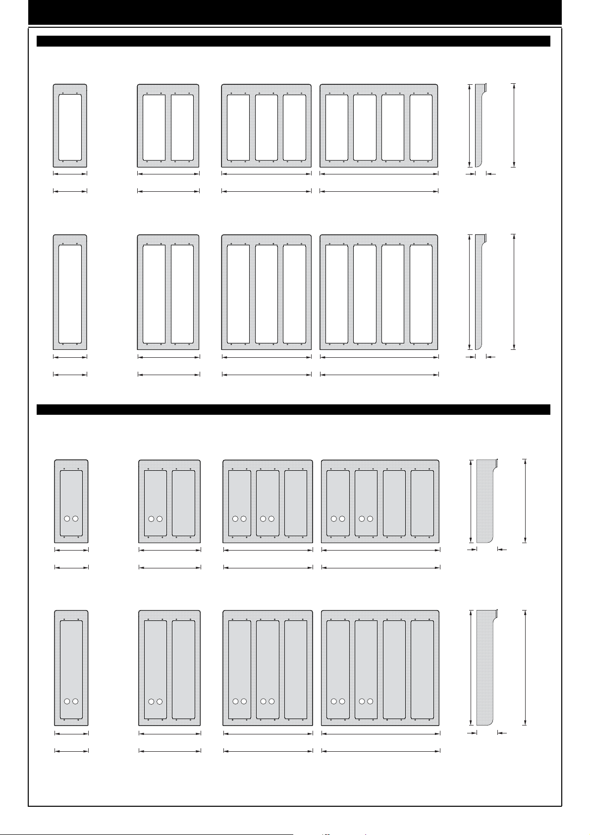
ALPHANUMERIC DISPLAY ENTRANCE PANELS: COMPONENTES
HEIGHT OF 2-MODULE
HEIGHT OF 3-MODULE
ENTRANCE PANELS
282
22
Art. 122D Art. 123D
100
ADDITIONAL ENTRANCE PANELS
ENTRANCE PANELS
22
100
FLUSH-MOUNTED BACK BOXES
Case width 88mm for 1 horizontal module and 50 mm depth.
Art. 9092
For 2 additional modules.
Height: 2 verical modules (248 mm)
Fig. 4
396
Art. 9093
For 3 additional modules.
Height: 3 verical modules (360 mm)
Fig. 5
Art. 122N
Art. 123N
3
Page 4
ALPHANUMERIC DISPLAY ENTRANCE PANELS: ACCESSORIES
RAINPROOF COVERS
1P21 1P22 1P23 1P24
for 1 panel for 2 panels for 3 panels for 4 panels
2 modules high alta 2 moduli 2 modules high 2 modules high
124 front side 224 front side 324 front side 424 front side
120 rear side 220 rear side 320 rear side 420 rear side
1P31 1P32 1P33 1P34
for 1 panel for 2 panels for 3 panels for 4 panels
3 modules high 3 modules high 3 modules high 3 modules high
124 front side 224 front side 324 front side 424 front side
120 rear side 220 rear side 320 rear side 420 rear side
SURFACE-MOUNTED BOXES WITH RAINPROOF COVER
1E21 1E22 1E23 1E24
for 1 panel for 2 panels for 3 panels for 4 panels
2 modules high alta 2 moduli 2 modules high 2 modules high
295
410
297
39,5
412
39,5
124 front side 224 front side 324 front side 424 front side
120 rear side 220 rear side 320 rear side 420 rear side
1E31 1E22 1E23 1E24
for 1 panel for 2 panels for 3 panels for 4 panels
3 modules high 3 modules high 3 modules high 3 modules high
124 front side 224 front side 324 front side 424 front side
120 rear side 220 rear side 320 rear side 420 rear side
295
410
297
74
412
74
4
Page 5

ENTRANCE PANEL WITH TRADITIONAL PUSH-BUTTONS: INTALLATION
FLUSH-MOUNTED ENTRANCE PANEL INSTALLATION WITH RAINPROOF COVERS.
Assembly of flush-mounted entrance panel requires the use of the flushmounted back boxes type 9092, 9093 respectively for 2 or 3 electronic
modules mounted vertically (Fig. 4A and 4B).
If the entrance panel uses more than one flush-mounted back box, the
rainproof covers must also be used (see plates WITH ALPHANUMERIC
DISPLAY: accessories on page 4, series 1Pxx), according to the number
of modules fitted vertically or horizontally.
Installation:
-
If the installation requires a combination of several back boxes, use the
hooks supplied with the back boxes to secure them together (Fig. 8).
- Install the back box with the upper edge at a height of approx. 1,65 m
from the ground (Fig. 1).
- Fix the terminal block of the electronic unit under the module holder
frame by means of the screws supplied (Fig. 7).
- Fix the rainproof cover to the flush-mounted back box using the
screws supplied (Fig. 7).
- Fix the module holder frames to the frames and the back boxes (Fig. 7).
- Connect the terminal box of the electronic unit to the system.
- Connect the electronic unit to the terminal block by means of the
wiring on the upper section.
- Connect the additional modules, if any, and insert them.
- Insert the electronic unit.
- Insert the microphone in the lower right section of the module holder
frame (Fig. 5).
Pay attention that the microphone cables are inserted in the external
slot of the electronic module (Fig. 5A, 5B).
- Close the entrance panel, attaching the plate first from the upper sec-
tion and then securing the lower section by means of the special key
on the head section.
- Perform the programming phases (page 6).
SURFACE WALL-MOUNTED ENTRANCE PANEL INSTALLATION
Assembly of the surface wall-mounted entrance panel requires the use
of the back boxes series 1Exx.
Installation:
- Fix the electronic unit terminal block under the module holder frame
by using the screw provided (Fig. 8).
- Fix the module holder frames to the frames and back boxes (Fig. 8).
- Connect the terminal block of the electronic unit to the system.
- Connect the electronic unit to the terminal block by means of the
cable present on the upper section (Fig. 2).
- Connect the additional modules, if any, and insert them.
- Insert the electronic unit.
- Insert the microphone in the right lower section of the module holder
frame (Fig. 5).
Pay attention that the microphone cables are inserted in the external slot
of the electronic module (Fig. 5A, 5B).
- Insert the module plates in the module holder frames (Fig. 8).
- Close the entrance panel, attaching the plate first from the upper sec-
tion and then securing the lower section by means of the special key
on the head section.
- Perform the programming phases (Pag. 6)
Fig. 5
Fig. 6
Fig. 7
Fig. 5A
Electronic unit without module holder frame
Fig. 5B
Electronic unit with module holder frame
Fig. 8
part. 1
Microphone cable
Microphone cable
5
Page 6
PARAMETERS FOR PROGRAMMING
R
4
GHI
R
R
PRELIMINARY OPERATIONS
Having installed and connected all the devices, power up the
system and check the LEDs on the power supply units to make
sure that they all supply power. Before carrying out any programming operations on the devices, wait for at least ten seconds
from the moment at which the system is powered up.
It is advisable to programme the call codes of the interphones and monitors after programming (if required) the
technical parameters of the entrance panels and/or switchboard.
PROGRAMMING THE TECHNICAL PARAMETERS OF THE
ENTRANCE PANEL
The entrance panel is supplied with a basic programme already
loaded, which can be modified according to the instructions
below. Programming must be carried out if the pre-set parameters do not meet the requirements of the system. There are three
ways of programming the entrance panel: with the entrance
panel keypad, with programmer Type 950B and with a Personal
Computer by means of the software Type 94CT and interface
6952.
Programming the entrance panel with the numerical keypad
(with entrance panel connected and powered up):
A) Entry to programming mode with the entrance panel keypad using the password.
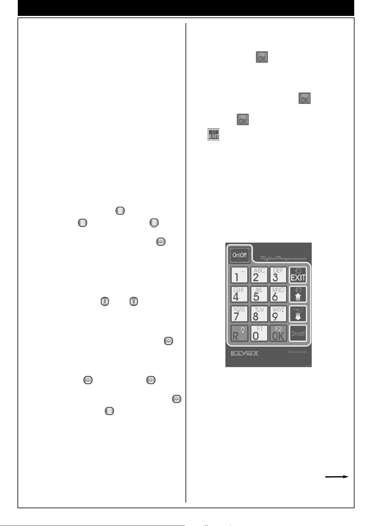
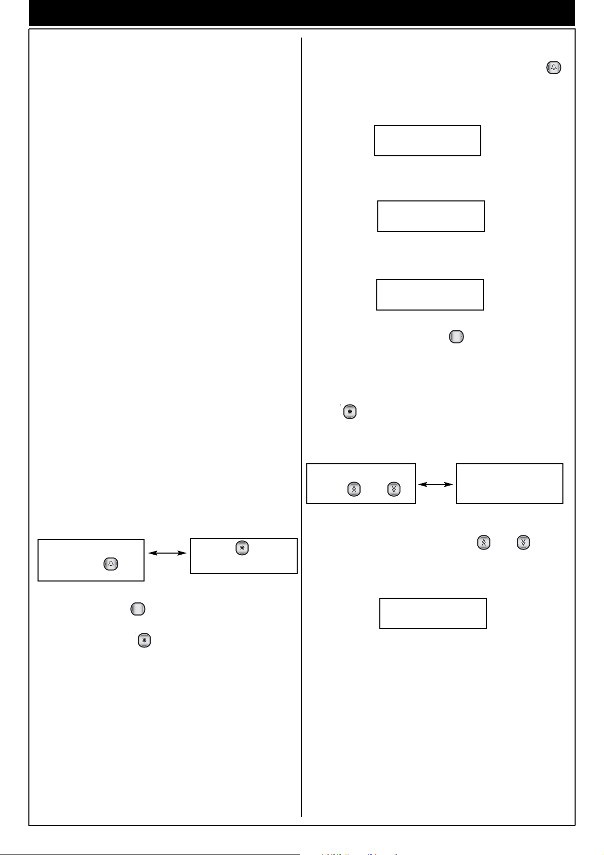
PROGRAMMING WITH Type 950B: (refer to the relevant
manual for a complete description)
With the entrance panel powered up, disconnect 950B (by
means of terminals 1, 4 and 5), select "PROG.PARAMETERS"
from the menu and press " " to confirm. The entrance panel
then goes immediately into programming mode, the message
"Ser.PROG" appears on the display and the panel emits a short
acoustic signal (it is not necessary to carry out operations on the
entrance panel to access programming). To scroll through the
parameters (without changing them) press " " or the "down"
arrow key repeatedly. Change the number on the display if nec-
essary and press " " to confirm. To complete programming,
press " " and make a call to verify that the entrance panel
has exited programming mode.
Cancel all operations by pressing ; the display must be
OFF. While keeping " " pressed down, press " ".
When the symbols "- - - - - - - - " appear on the display, enter the
code "123 or 0123" (standard password) and press " ".
If the operation has been carried out correctly, the message
"PROGRAM" will appear on the display.
If it does not appear, repeat the procedure.
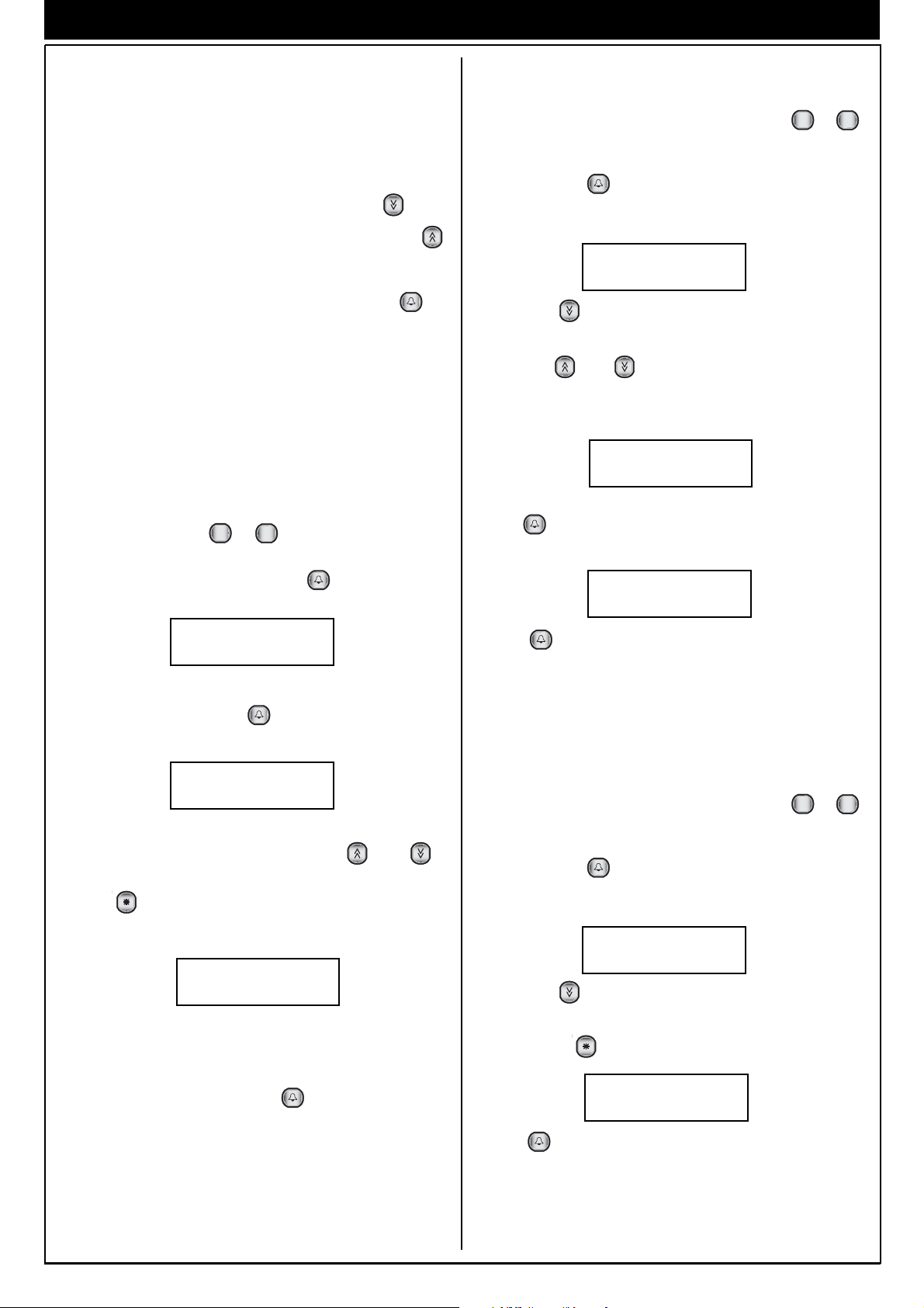
B) Direct entry to programming mode for programming with
the entrance panel keypad (if you have lost the password).
Disconnect the entrance panel from the terminal block, wait for
2-3 seconds, then press the “ ” and “ ” push-buttons at
the same time and power the installation again. After few seconds, if the operation has been carried out correctly, the message “PROG.” appears on the display.
If this does not happen, repeat the operation.
Once you have entered the programming phase, press " " to
go to the first parameter ("INITI_US" = "Initial User"). The display
will show the parameter name “Final User ” (e.g. 0000 0001). To
modify the value, use the number keys; if you make a mistake,
use the number keys only to correct the value entered. To con-
firm the change, press " ". Pressing only the " " key does
not change any saved parameters, but displays the set values
Keyboard programming 950B
one after the other. On completion of programming, press "
PROGRAMMING WITH SOFTWARE ON PC Type 94CT "ANALYZER" :
" followed by the push-button " " to exit the technical programming phase.
By means of a graphic interface, the software enables you to
simultaneously display/modify all the relevant parameters. It also
enables you to save the programmes you set for the purpose of
The parameters can be programmed or consulted repeatedly.
filing or future replacements (and for rapid, multiple program-
ming). For user instructions, refer to the relevant manual.
The set values remain in the memory until they are programmed
again (if applicable) even if the power is switched off.
N.B.: the term optional indicates that parameter modification is not necessary, but is left to the installer's
discretion (e.g. conversation time, codes for door lock
release etc.).
6
Page 7

PARAMETERS FOR PROGRAMMING
ENTRANCE PANEL TECHNICAL PARAMETERS TABLE
No. Parameter Abbreviation on Minimum Maximum Default Description When to change the value
1 Initial User Initial User 1 99999999 1 Lowest call number (filter on the codes Required in building complexes.
2 Final User Final User 1 99999999 99999999 Highest call number (filter on the codes Required in building complexes.
3 Entrance panel code Panel number 0 99999999 0 Identification/call number of the panel In systems with porter switchboard
4 Not used - - - - - - - -
5 Technical Tecnic. Prg. Key 1 9999 123 Password for access to technical program- Required in all cases.
programming code 00000123 ming parameters programming with the
6 Rubric. key Rubric. key Not used
7 Code for door Key 0, R-1, C 0 2 1 Password for door release from Optional.
release keypad (0 = 0, 1 = R+1, 2 = C).
8 Audio active Audio active 0 1 1 When the parameter is set to 0, the entran- Optional, but only for building complexes.
9 Language English Language 0 1 0 (0 = Italiano, 1 = English). Optional.
10 Enables entrance
panel operation 00000000 panel (0 = No, 1 = Yes).
11 Enables priority Priority Enab. 0 1 0 Entrance panel with priority Optional, but only for entrance
12 Enables sequential Lock Enable 0 4 1 Enable the door lock activation: Optional
13 Enables camera Camera Enable 0 1 1 Indicates whether the entrance panel Required with entrance panels
14 Enables sound on Sound Pan. Ena. 0 1 1 Enables repetition of the call sound on Optional.
15 Enables Autostart Ena. 0 7 0 Enables self-activation of the monitor Optional.
self-start 00000000 /interphone by means of commands F3,
16 Not used - - - - - - - - Enables
17 Enables conference Conferen. Enable 0 1 0 Enables activation of conference To be used only for diagnostic
18 Enables call to Call Cent. Enab. 0 1 0 Enables calling to main switchboards Optional.
switchboards 00000000 with respect to the entrance panel.
19 Duration of Convers. time 1 255 12 Maximum conversation time Optional.
conversation 00000012 (in seconds x 10, i.e. 12 = 120 seconds).
20 Duration of ringone Ring Dutration 1 255 1 Activation time of call signal Optional.
21 Answer time Answer time 1 255 30 Maximum waiting time for reply Required in building complexes.
22 F1 function time F1 time 0 255 1 Activation time of function F1 Optional.
23 F2 function time F2 time 0 255 1 Activation time of function F2 Optional.
24 Door lock time Lock time 0 255 1 Lock activation time (in seconds). If Optional.
25 End of conversation End Conv. P. Tim. 0 255 0
With warning time 00000000 from an entrance panel with priority, the
26 Counter Error Counter 0 255 0 Optional.
27 Enables the window Up Window Ena. 0 1 1 Enables the "initial user" - "final user" Optional, but only for building complexes.
above 00000001
28 Enables display of the Debug Visu. Ab. 0 1 0 Enables the debug messages on the
control parameters 00000000 entrance panel display (0=No, 1=Yes).
29 Not used - - - - - - - - Not used
30 Reserved parameter Reserved Param. 0 255 1 Reserved parameters can be displayed As indicated by the manufacturer
31 Coded door lock Key lock N°001 0 99999999 0 Memory location for 1st door release Optional.
release 00000000 code.
32 Coded door lock Key lock N°002 0 99999999 0 Memory location for 2nd door release Optional.
release 00000000 code.
33 Coded door lock Key lock N°002 0 99999999 0 Memory location for 2nd door release Optional.
release 00000000 code.
programmer display value value
English
00000001 in transit from terminal 6 to terminal 1).
99999999 in transit from terminal 6 to terminal 1).
00000000 (for calls/analysis from switchboard). and several electronic entrance panels.
00000001
"R + 4" function.
00000222
ce panel switches off the audio completely Not used
00000001
Panel Block
00000000 (0 = No, 1 = Yes). panels in parallel.
00000001 1 = the door lock is activated only by the
00000001
00000001 panel the panel itself (0 =No, 1 =Yes).
00000001
00000000 between the entrance panel and 2
00000001 (in seconds).
00000030 (in seconds).
00000001 (in seconds). If set to 0, activation is
00000001 (in seconds). If set to 0 activation time
00000001
00000000
00000099
00000001 by entering a secret code.
0 1 0 Disables operation of the entrance panel Optional,
interphone called by the respective
entrance panel.
2 = The door lock is activated in sequence
with that of a main entrance panel.
The panel must be placed between the
main entrance panel and the called
interphone.
3 = Enables both points: 1 and 2.
4 = The door lock is activated in any case,
also when the interphone has not been
called.
6 = Function 4 + Function 2
is fitted with a camera (0 = No, 1 = Yes).
F4 and F5. Add the values of F3,
F4 and F5 to indicate which functions
enable self-start (0 = No, 1 = F3,
2 = F4 and 4 = F5). With 7=1+2+4 switches
on automatically
interphones/monitors (the second
interphone/monitor is called with the
" key).
"
*
(by pressing the key )
reduced to 0.5 sec.
is reduced to 0.5 sec.
set to 0, activation is reduced to 0.5 sec.
End of conversation warning: after a call
existing communication receives a
warning that it is about to be interrupted,
and is suspended after the the set number
of seconds (0 = no warning).
filter also for data in transit from terminal
1 to terminal 6 of the entrance panel
(0 = No, 1 = Yes).
with F3, F4 and F5.
supplied with internal or external camera.
Optional.
7
Page 8

PARAMETERS FOR PROGRAMMING
No. Parameter Abbreviation on Minimum Maximum Default Description When to change the value
68 Coded door lock Key lock N°36 0 99999999 0 Memory location for 36th door release Optional.
release 00000000 code.
69 Activation F2 Code F2 0 99999999 0 Memory location for code of the F2 output Optional.
70 Activation F2 Code F2 0 99999999 0 Memory location for code of the F2 output Optional.
1st number in memory
71
2nd number in memory
72
programmer display value value
00000000 activation. code.
00000000 activation. code.
Door lock key 0 99999999 0 This is a pre-saved preferential number Optional.
00000000 which can be associated with the pressing
2nd number in memory 0 99999999 0 This is a pre-saved preferential number Optional.
00000000 which can be associated by pressing of
of key
the key
8
Page 9
PARAMETERS FOR PROGRAMMING
1
R
4
GHI
R
4
GHI
R
Description of functions:
- Initial User "INITIAL USER" (1) and Final User "FINA_US"
(2). To be programmed in the case of a system for a building
complex. The two values must be set only on the secondary
entrance panels. These two parameters serve to switch the
secondary entrance panel to the engaged state when a call is
being made from another entrance panel or from a switchboard with a number between the lowest and the highest
number. The call must originate from a main entrance panel
or from a switchboard and not from another secondary
entrance panel. When the entrance panel is in the engaged
state, no operations can be performed. If the call number is
not between the lowest and the highest number, the secondary entrance panel does not go into the engaged state and it
is therefore possible to make calls to the riser.
- Entrance panel code "FINAL USER" (3). This is the call
code to assign to the entrance panel (similar to the interphone
code). It does not need to be set on systems with 4-digit coding. It may be necessary to programme this code in the following cases:
1) On systems for building complexes consisting of secondary entrance panels and a 945B switchboard, when you want
to make calls from the secondary entrance panels (upstream)
to the porter switchboard. In this case it is possible to call
back the secondary entrance panel from the switchboard and
communicate.
2) When you want to use the entrance panels in conjunction
with the "Software" switchboard (Type 95CD). In this case, it
is possible to activate the various functions from the switchboard (door release, F1, F2, etc.) on each entrance panel in
the system. It is also possible to analyse (and change) the
individual parameters of each panel from the switchboard.
NB: In either case, bear in mind that the entrance panel number must be unique and different from the call codes of the
interphones and monitors.
- Technical programming code "TECNIC. PRG. KEY" (5). It
is advisable to change this value. This is the number that is
requested when you enter the technical parameter programming phase using the entrance panel keypad. If the value is
set to "0000" the entrance panel goes automatically into pro-
gramming by pressing " " and " " simultaneously. To
enter the programming phase press " " and " " simul-
taneously, enter the password (e.g. 0123) and press " ".
- Agenda programming code "RUBRIC. KEY" (6): this is the
password to be entered to enable access to the name
entry/deletion functions. This should be different from the programming password (given the different users involved). The
number range is 1 to 9999. The default setting is 222
- Code for door release "KEY 0, R-1, C" (7). To be pro-
grammed at your discretion. Indicates the way in which you
can access the door release function, by using the entrance
panel keypad. By setting the parameter with the numbers 0, 1
and 2, you select the following three methods respectively: 0)
With display OFF and entrance panel not in communication,
press "0".
1) With display OFF and entrance panel not in communication,
press " " and " " simultaneously.
2) With display OFF and entrance panel not in communication,
press " ". To release the door, refer to the codes recorded
in parameters 31 to parameter 49.
Parameter “AUDIO ACTIVE” (8)
(0, 1 default 1) To be modified optionally only for building complexes.
To be modified only for particular uses. Normally (value = 1) the
entrance panel in rest mode is set to “audio active” (i.e. ready to
communicate on audio mode). When the parameter is set to 0,
the entrance panel switches off the audio completely (this is useful only when more entrance panels are installed and connected
in parallel and to be used with a switchboard or during the interphone programming, to avoid the Larsen effect owing to the
simultaneous activation of more entrance panels).
- Language "ENGLISH LANG." (9). To be programmed at
your discretion. The function refers to the displayed messages language. If the parameter is set to 0, the messages
are displayed in English, otherwise in Italian.
- Enable entrance panel operation "PANEL BLOCK" (10).
To be programmed at your discretion. If the parameter is set
to "1", this prevents calls from being made to the
monitor/interphone riser covered by the entrance panel.
- Enable priority "PRIORITY ENAB" (11). To be programmed
at your discretion in the case of a system with entrance panels in parallel. By activating this function, the entrance panel
does not go into the engaged state when another entrance
panel, in parallel with the first, makes a call. In this state, the
entrance panel with priority can interrupt a conversation in
progress to make another call. This function only affects
entrance panels connected in parallel; with each other; for
systems for building complexes the secondary entrance panels still go into the engaged state if the call originates from a
main entrance panel or a switchboard.
- Enable sequential lock "LOCK ENABLE" (12). To be programmed in the case of a system for a building complex. The
function refers to secondary entrance panels. If enabled, this
makes it possible to activate the terminal "S" for door release
on the secondary entrance panel, when a monitor or an interphone sends the door release code while in conversation with
the main entrance panel. This then enables activation of both
the door release for the secondary entrance panel and the
door release for the main entrance panel. Adding 2 to this
value also enables the possibility of door release "from below"
(e.g. from an underlying switchboard in communication with
the entrance panel itself).
- Enable camera "CAMERA ENABLE" (13). To be pro-
grammed with type 8847, 8847/C entrance panels. Indicates
that the entrance panel is a video version of video type
equipped with a camera. This enables management of correct
monitor activation and shutdown of the monitors in the system
in the correct way.
- Enable sound in entrance panel "SOUND PAN. ENA." (14).
To be programmed at your discretion. When enabled, this
function activates an acoustic signal emitted by the entrance
panel when a call is sent.
- Enable self-start "AUTOSTART ENA" (15). Enables the
entrance panel itself to be self-activated by an
interphone/monitor. To operate in this mode, the
interphone/monitor must be configured with the appropriate
key and the entrance panel must have the 8-digit "coding system" parameter.
In this case the self-start key, on the interphone/monitor
(which enables self-start on a maximum of 3 different entrance
panels), sends the commands sequentially each time it is
pressed, the commands F3, F4 and F5; i.e. the first press
sends the F3 command (and emits the confirmation sound),
the second press sends the F4 command (emitting 2 sounds)
and the third press sends the F5 command (3 sounds). If you
press the key again, the sequence repeats itself (NB: 30 seconds after pressing the key, the sequence returns to its initial
state, i.e. F3 command). To enable the self-start function
according to one of the commands F3, F4 and F5 or according to a combination of the three, assign to the parameter the
values set out in the table below:
Command Command
parameter value
0 None
1F3
2F4
3 (1+2) F3 and F4 (with either F3 or F4)
4F5
5 (1+4) F3 and F5 (with either F3 or F5)
6 (2+4) F4 and F5 (with either F4 or F5)
7 (1+2+4) F3, F4, F5 (with either F3, F4 or F5)
9
Page 10

PARAMETERS FOR PROGRAMMING
R
- Enable conference "CONFEREN. ENAB." (17). Enabling
this parameter allows the entrance panel to call several interphones simultaneously. In this case, the first interphone will be
called with the code followed by the " " key, and the others must be called by keying in the codes followed by the
" " (asterisk) key.
- Enable call to switchboards "CALL CENT. ENAB” (18).
This parameter affects systems for building complexes with 8digit coding (parameter "8") and with porter switchboard Type
945B. If enabled on secondary entrance panels, it allows
entrance panels to call a switchboard located "downstream" of
the entrance panels (the entrance panels in question are
those with terminals 6-8 connected to the switchboard). The
other relevant parameters are the entrance panel code
(parameter No. 3) and the corresponding parameter of the
switchboard Type 945B. To call the switchboard press "double
arrow down" key, which will, in turn, call the relevant entrance
panel.
- Duration of conversation "CONVERS. TIME" (19). To b e
programmed at your discretion. This is the time, expressed in
tens of seconds (e.g.: 12=120 sec), which the entrance panel
controls from the moment at which the handset is picked up
after the call. On expiry of this time, the entrance panel switches off the interphone.
- Duration of ringtone "RING DURATION" (20). If the system
includes secondary entrance panels (building complex) or a
switchboard, the activation time of the call signal of the main
entrance panel must be greater than 1 second compared with
the corresponding time, set on the secondary entrance panels
or the switchboard. In other cases, the parameter can be
changed at the discretion of the installer. This parameter represents the time, expressed in seconds, for which the
entrance panel activates the terminal CH. Terminal CH activates the call generator in the power supplies Type 6941 and
6948.
- Answer time "ANSWER TIME" (21). To be programmed at
your discretion. This is the time, expressed in seconds, for
which the entrance panel waits from the moment at which the
call is terminated to the moment at which the handset of the
interphone is picked up. If the handset is not picked up within
the reply time, the entrance panel switches off the interphone.
If, however, the handset is picked up before the time expires,
the entrance panel starts counting the conversation time (see
parameter 19 "Duration of conversation").
- Function time F1 "F1 TIME" (22). To be programmed at your
discretion. This is the time, expressed in seconds, for which
the entrance panel activates terminal F1. Terminal F1 serves
to activate a relay connected to terminals R1 and 4 of the
power supplies Type 6941, 6942 and 6948.
- Function time F2 "F2 TIME" (23). To be programmed at your
discretion. This is the time, expressed in seconds, for which
the entrance panel activates terminal F2. Terminal F2 serves
to activate a relay connected to terminals R2 and 4 of power
supplies Type 6941, 6942 and 6948.
- End of conversation warning time "END CONV. P, TIM"
(25). This function regards systems to systems for building
complexes. The parameter indicates the time, in seconds,
that elapses from the call of a main entrance panel to the
interruption of a conversation in progress on a secondary
entrance panel. Interruption of the conversation will be indicated by an acoustic signal and the message "END CON"
before going into the engaged state. NB: in normal use it is
advisable to leave the parameter at 0.
- Number of digits in pre-code "ERROR COUNTER" (26).
The parameter determines the number of digits (maximum 4)
to be used for the pre-code in reference to parameter "4".
- Enables the window above "UP WINDOW ENA." (27). If
the parameter is enabled, the parameters "initial user" (1)
and "final user" (2) are used for filtering the codes descending from terminal 1 to terminal 6 of the secondary entrance
panels. This function is for use in systems for building complexes in which there are several secondary entrance panels
connected in double parallel (as well as the connection of terminals 1, terminals 6 are also connected). Connection in
double parallel is necessary so as to make it possible to
make calls from all the secondary entrance panels to the
switchboard Type 945B. On secondary entrance panels in
double parallel the parameter must be set to 1 on all the panels except for one, which must be kept at 0. Enabling of this
parameter means that the "initial user" (1) and "final user" (2)
parameters of each secondary entrance panel must be duly
modified: the secondary entrance panels with the parameter
27 to 0 must have the parameters "initial user" (1) and "final
user" (2) set in accordance with the lowest and highest numbers of the interphones (as for normal use), while for the secondary entrance panels with the parameter 27 to 1, they
must have the parameters "initial user" (1) and "final user" (2)
respectively coinciding with the parameter "entrance panel
code" (3).
- Enable display of control parameters "DEBUG VISU. AB"
(28). If enabled, this parameter makes it possible to show
diagnostic messages on the entrance panel display. The
messages are activated in response to calls, door release,
activation of functions, etc. Enabling the debug can be very
useful for checking the reception of "digital" commands from
and to the entrance panel, and in general, for checking the
connected devices (e.g. by pressing the call key of an interphone above, if the call is successful, reception of the command is shown on the display).
- Reserved parameter "RESERVED PARAM" (30). This
parameter makes it possible to enable the display of further
parameters reserved for special uses. The parameter must
only be changed if instructed by the manufacturer.
- Coded door lock “KEY LOCK N...” (31, 32, ......68). To b e
programmed at your discretion. In these 20 parameters it is
possible to save 20 different codes of 8 digits each, to
release the door from the entrance panel. First use the 0 key
or the and 1 keys or the key (see parameter 7) to
activate the function, then key in one of the saved codes to
activate terminal "S" on the entrance panel.
- Door lock release "LOCK TIME" (24). To be programmed at
your discretion. This is the time, expressed in seconds, for
which the entrance panel activates terminal S. Terminal S
serves to activate the lock connected to terminals 15 and S1
of the power supplies Type 6941, 6942 and 6948.
10
Page 11
PARAMETERS FOR PROGRAMMING
R
R
Coding F1 “F1 CODE” (69). As above, but as the code has
been entered, the F1 output is activated in the memory.
Coding F2 “F2 CODE” (70); As above, but as the code has
been entered the output F2 is activated in the memory. Number
of memory (F1, F2). To be programmed at will. In these two
parameters it is possible to store two different codes consisting
of 8 digits each in order to effect calls in a quick way by using the
“arrow up” and “arrow down” panel push-buttons.
“1 MEMO NUMBER” (71): Enable switchboard call: if set to = 1
enables recall of a switchboard (using “ ”).
“2 MEMO NUMBER” (72): Number in memo: if other than 0
enables the association of a number for immediate calls (using
the “ ”).
KEYPAD DESCRIPTION
Keys 0 - 9 DIAL NUMBER: serve to dial the user number for
calls and change the values of technical parameters during entrance panel programming.
Key RESET: serves to cancel and interrupt each con-
versation. The key is also used to exit the technical programming phase.
Key USER CALL: serves to send the call after dialling
the number. In the technical programming phase,
the key is used to confirm the changes made and
move onto the next parameter.
If the following conditions are met, the key
can also be used to access the door release function from the entrance panel. The conditions are:
parameter "7" must be "2", the entrance panel
must not be in communication with an interphone
and the display must be OFF.
Key Asterisk key:
Conference call key, enables simultaneous communication with 2 interphones/monitors and the
entrance panel. To use this function, refer to
parameter "17".
Key During the search phase from the name list, it
scrolls to the previous name.
Key During programming of the technical parameters,
enables you to move from the 1st parameter (initial user) to the 31st parameter (coded door lock).
It is also possible to assign a pre-saved number
to this key for rapid calling. In this case, the nametag must show the name of the corresponding
interphone.
0
+
Key DOOR RELEASE FROM ENTRANCE PANEL:
If the following conditions are met, the 0 key can
also be used to access the door release function
from the entrance panel. The conditions are:
parameter "7" must be "0", the entrance panel
must not be in communication with an interphone
and the display must be OFF.
Keys and
R
1
DOOR RELEASE FROM ENTRANCE
PANEL:
If the following conditions are met, pressing keys
R and 1 simultaneously gives access to the door
release function from the entrance panel. The
conditions are: parameter "7" must be "1", the
entrance panel must not be in communication
with an interphone and the display must be OFF.
Keys and
R
4
GHI
ENTRY TO PROGRAMMING: when
pressed simultaneously, these keys give access
to the technical programming phase.
ENTRANCE PANEL OPERATION
Call from entrance panel to user; on the keypad, dial the num-
ber of the user in question and press " ". When you press
" " the entrance panel will send the call to the interphone. If
parameter "14" is enabled, the call signal sent to the interphone
will be repeated by the entrance panel receiver. On completion
of the call, the entrance panel will start to count down the reply
time (parameter 21), until the handset of the interphone is
picked up. On expiry of the time, the entrance panel will disconnect automatically from the interphone. If the handset is picked
up before the reply time expires, the entrance panel will go into
communication with the interphone for the full conversation time
(parameter 19). If the handset is hung up before the conversation time expires, the entrance panel will disconnect from the
interphone after about 5 seconds. To open the entrance panel
lock, from the interphone or from the monitor or from the switch-
board, press the key marked with the symbol . Bear in
mind that the lock can only be opened when the entrance panel
is in communication with an interphone or the switchboard;
whereas the auxiliary functions can be activated regardless of
whether the entrance panel is in communication or not. If you
want to interrupt any operation from the entrance panel, use the
" " key.
Key During the search phase from the name list, it
scrolls to the next name.
Key During programming of the technical parameters,
enables you to move from the 1st parameter (initial user) to the 31st parameter (coded door lock).
The key is also used for calling the porter switchboard Type 945B if the parameter "18" is enabled.
It is also possible to assign a pre-saved number
to this key for rapid calling. In this case, the nametag must show the name of the corresponding
interphone.
11
Page 12
PARAMETERS FOR PROGRAMMING
R
R
1) GENERAL OPERATION:
INTRODUCTION: Type 8847 (digibus video entry panel with
agenda) and type 8844 (digibus audio entry panel with agenda)
enable calls to any digibus number (exclusively for 8 digit
systems) both by entry of the number and searches of stored
numbers (in a previously memorised data-base).
The maximum number of names is approx. 600 (extendible on
request), with 16 characters available for each name (the name
can be separated into surname and name, but always within a
maximum of 16 characters). It is also possible to associate several names to call the same number (such as the names of
husband and wife).
A number of accessory data can also be associated with each
name (see below for relative use).
- A search for names can be via sequential scroll keys (forward/back) or, the faster option, by entry of the initial letter of
the name.
- Once the name is found, the user displayed can be called
immediately without having to re-enter the number.
The numerical keypad can also be used to directly enter the
required user number (if known).
- The insertion/cancellation of names may be made directly
from the key board (on entry of a password) or by means of a
software with type 6952. In this case the module is connected
to the PC serial supplied by means of a suitable interface
(type 6952) connected between terminals 4 and 1.
- The database management software, as well as enabling simple and rapid management of data, offers the following main
functions:
- Intuitive and fast use thanks to the evolved graphic interface
(similar to “Windows”)
- Entry, deletion and modification of one or more users.
- Storage of data of specific files on the PC.
- Safety: in the event of damage to the switchboard, data can
be restored at any moment with no waste of time.
- Possibility of repeating the same settings on multiple switchboards without the need of re-entering the database.
- Reading of data by switchboard with recovery also of data
entered manually.
- Possibility of entering additional information as a description
(notes) [to be completed]
2) BASE STATUS:
The status in which the agenda is in the rest condition. In this
status, the display shows the following 2 messages alternately.
3) DIRECT ENTRY OF A NUMBER:
If the user knows the number of the internal unit to be called, this
can be entered directly via the keypad followed by the key
to make the call. A call is then made to the entered number, and
during this phase the display shows the called number indicating
the call in progress:
00000123
CALLING
After the ring tone, the panel sets to standby for an answer (by
the internal unit) displaying:
00000123
AWAITING ANSWER
When the internal unit answers the call, the first message is
replaced on display by the notification of the start of conversation:
00000123
TAL KING
When the internal user replaces the handset (indicated by the
relative message) or after the key is pressed, the call can
be interrupted. This operation returns the panel to the base status with relative message on display (see paragraph above).
4) USING THE NAME AGENDA:
To activate the “Agenda” function, from the base status, press
the key . When the key is pressed, the display shows the
stored user names for approx. ½ second and then the following
2 messages alternately every 3/4 second:
SCROLL LIST WITH
KEYS and
ENTER INITIAL
OF REQUIRED NAME
At this point the caller can scroll through the stored names (in
ENTER NUMBER
AND PRESS. .
PRESS
FOR NAME LIST
alphabetical order) by means of the keys and , or use
the search function to find the required name or names “nearby”.
In this search phase, the display shows the selected name with
internal number:
As these messages convey, these keys (which are reset each
time they are pressed and automatically at the end of each
notification) from this status the number to be called can be ente-
red directly by pressing , the user can search the agenda to
find or recall a stored number/name.
In this phase, as shown on display, for faster access to a name,
press the key with the initial letter of the name to be searched
MICHELI PAOLO
Number=00000034
(NB: the keypad has the alphanumeric characters described
below). When the key is pressed, the display shows the first
name with the initial entered or the letter after the one pressed.
12
Page 13
PARAMETERS FOR PROGRAMMING
7
PQRS
R
7
PQRS
R
7
PQRS
R
NB1: Given that each key has 3-4 letters, when pressed repeatedly the key enters the letters according to the number of times
the key is pressed (for example, if the key (6MNO) is pressed
once the display shows the first name with the letter M or next letters if pressed consecutively. Therefore it is not possible to move
directly to the letter O or N as the display starts from M and then
the user can scroll the list with the relative keys.
NB2: Note that the forward scroll (by means of key ) is nor-
mally faster than the back scroll (by means of key ).
Therefore searches are recommended starting from the first letters on the key.
Once the name to be called is selected, press key and
communication will proceed as per the number entry procedure
(see previous paragraph).
5) ENTERING/DELETING/MODIFYING USERS VIA THE KEY-
PAD:
This stored user management mode should only be used occasionally (periodically on site). It should normally be avoided,
given the time-consuming procedure, and also because it does
not enable a trace to be maintained of stored data on file for
restoring data when required.
ENTERING A NAME VIA THE KEYPAD:
1) Press and hold keys + . This displays the message
“--------“ to request the password of previously memorised users
DELETING A NAME VIA THE KEYPAD:
To delete a name, enter the user entry mode, scroll through to
the required name and delete. Proceed as follows:
1) Enter user programming mode by pressing keys +
simultaneously, to display the message “--------“ requesting
the user password previously memorised (default=222) and
then press key .
2) At this point the message is displayed (as described above)
requesting entry of the new number:
New Number?
3) Press the push-button to enter the name cancellation
mode.
4) Use keys and to scroll through the list to the name
to be deleted. To speed up the search, press on of the keys
with an alphanumeric letter (ABC,DEF,GH..) to reach the
required letter.
ROSSI MARIO
11223344
5) When the required name (number) is displayed, press the
key to delete. A request is then displayed to confirm
deletion:
(default=222) after which press the key . The following data
are then requested:
2)
New Number?
A new internal number for entry is requested. Enter by means of
the numerical keys and press to confirm.
New Name? A
Entry of a new name is requested, proposing the first letter “A”.
To select the first required letter, press keys and as
required. When the required letter is displayed (such as M) press
the key to confirm and move to the next letter. The first
selected letter is shown on the display followed by A for the
second letter.
New Name? MA
Proceed as above by means of the scroll keys and confirming all
the remaining letters (max 16). (NB: To enter a space move back
from the letter “A” to select the space (approx. 32 characters
before).
When the name is complete, press to confirm and save.
After a brief standby interval the panel returns to the base status.
For subsequent entries, repeat the above operations as described.
To interrupt the procedure in any phase, press “R” (during letter
entries, this returns to the previous letter).
ROSSI MARIO
CANCEL???
6) Press to confirm deletion. After a brief interval, the deletion message is displayed and the panel returns to base status.
NB: After point 4 in the procedure, the deleted data cannot be
retrieved. Re-enter if necessary.
NB2: Always pay attention to the deletion confirmation messages and verify correct deletion (scrolling through the list to
check).
DELETING ALL NAMES VIA THE KEYPAD:
1) Enter user programming mode by pressing keys +
simultaneously, to display the message “--------“ requesting
the user password previously memorised (default=222) and
then press key .
2) At this point the message is displayed (as described above)
requesting entry of the new number:
New Number?
3) Press the push-button to enter the name cancellation
mode.
4) Pressing the push-button, the message:
Canc. All.
appears.
???
5) Press to confirm deletion. After a brief interval, the deletion
message is displayed and the panel returns to base status.
NOTE: Always pay special attention to pay attention to the
messages for cancellation confirmation.
13
Page 14

PARAMETERS FOR PROGRAMMING
R
4
GHI
R
R
1
R
0
+
KEYS TO RELEASE THE DOOR LOCK FROM THE KEYPAD:
If the entrance panel is not engaged in a conversation or is not
locked in the engaged state, indicated by the message
"ENGAGED", it is possible to release the door covered by the
entrance panel by means of the entrance panel keypad.
On this version, the door lock can be opened (on terminal “S”) by
entering the codes directly from the keypad. The main characteristics related to the operation are the following:
- Possibility of storing up to 38 different keys (with maximum 8
coding digits). Possibility of canceling/entering a single key
directly from the keypad.
- Possibility of managing/storing/re-establishing the key also by
means of a PC and specific software enclosed.
- During use, possibility of displaying the message (of confirmation or refusal) on the alphanumeric display.
- If the code entered it is not present in the storage list, the
respective code can always be sent to the serial (different for
each entrance panel), to enable activation as to allow the possible activation of “infinite” different devices (for example
through relay 170F) also remote.
To release the door lock:
To access this function, refer to the value set in parameter 7 of
the entrance panel; if the value is 0, press " "; if the value is
1, press " " and " " simultaneously; and if the value is 2,
press " ". Before pressing the key for access to the function,
it is advisable to cancel any operation in progress, by means of
the " " key, and then use the keys indicated previously. After
activating the function on the display, the following symbols will
appear "- - - - - - - -". To release the door, enter one of the codes
recorded in parameters 31- to 68 and then press " ". Note
that the code 0000 0000 cannot be used for door release.
To activate, proceed as per the lock procedure and enter the relative code in the memory.
NB: Warning: if the entered code is the same as that in the
“code” area, only the lock will be activated.
DISPLAY LIGHTING:
While the keypad lighting is permanently activated (to enable
identification of the keypad) the display brightness
varies according to use of the panel:
- When the panel is not used, the display brightness is set to
minimum (low profile display of initial message).
- When a key is pressed and during conversations the brightness is then set to maximum.
SPECIAL PARAMETERS TO BE PROGRAMMED:
- Error counter: parameter that counts the number of activations of the digital relay (due to short circuits on the digital line).
No programming is required, but it may be reset as necessary.
CONNECTION OF PC FOR DATA DOWNLOAD/UPLOAD:
Connect the PC serial cable by means of type 6952 to terminals
4 and 1. The length of this cable should not normally exceed a
few metres (given the transfer speed).
If the PC does not have a serial connector, the relative USB port
can be used, connected to a specific USB-RS232 adaptor. The
connection between the PC and card can be made with the
agenda correctly powered. If a connection is to be made to a
separate module (not connected), a supply voltage of 12-16 Vdc
is required between terminals 4 and 5 on the terminal board (possible from any power supply).
Wiring diagram
To store the door lock codes in the memory, proceed as follows:
- Enter the technical programming mode ( + ) followed
by the programming “password” (default value: 123)
- Scroll all parameters until you can enter the key zone (the following parameter is requested: “Chiave Ser.N 001”). Note: to
by-pass the scrolling of all parameters press the “doppia freccia giù” (double arrow down) parameter so as to reach immediately the first key).
- Scroll through to the position of the key to enter/modify (for
example “Chiave Ser.N 015” for the 15° key).
- Enter the code to store (without initial zeroes and with a maxi-
mum of 8 digits). Confirm with “ ” (bell).
- To exit programming mode press the “ ” push-button.
CODES FOR ACTIVATION OF FUNCTIONS F1 AND F2:
As well as the 38 codes mentioned above an additional 2 numerical codes can be entered in the memory (max. 8
digits) which can be used for activation of the control line for functions F1 and F2. This enables, in addition to activation of the
lock release via the keypad, activation of any connected accessory functions (such as an external light and/or accessory gate).
To memorise these codes, proceed as per the lock codes; scroll
through the 38 items using key , after which the message
“CODE F1” (or “CODE F2” is displayed when the key is pressed
again). Then enter the required code and confirm by pressing
.
14
Page 15

PARAMETERS FOR PROGRAMMING
DISPLAY OF SOFTWARE VERSION:
With the panel in normal operating status, press and hold keys
“1”+”2”+”3” simultaneously. This displays the date of the internal
software version (firmware): for example PG160605 means 16
June 2005.
AUTOTEST FUNCTIONS:
This is a function (for technical use) that enables the direct
display of the voltages on the 3 main lines of the bus (supply voltage, audio and digital). Press keys R+3 together on the panel to
display the following message (or similar):
V5=13,4 V1=11,7
V3=11,9
V5 corresponds to the supply voltage (between terminals 5 and
4)
V1 corresponds to the voltage of the digital line “to the cable riser
” (between terminals 1 and 4)
V3 corresponds to the voltage of the audio line “to the cable riser
” (between terminals 3 and 4)
The message, useful for quick analysis, is cleared automatically
after a few seconds.
During a call, if the voltage on the digital line (1) is too low (due
to a short circuit or power failure of the relative generator) the
function is activated automatically and the display shows the
relative message (indicating low voltage on the serial line):
ERR. SER. 1 LOW
15
Page 16

WIRING DIAGRAM
MINIMAL CONDUCTOR SECTION (mm2)
Conductors Ø up to 50 m. Ø up to 100 m. Ø up to 200 m.
4-5 0,75 mm
+ - and lock 1 mm
2
Others 0,5 mm
2
2
2
1 mm
1,5 mm
0,75 mm
1,5 mm
2
2
2,5 mm
1 mm
2
2
2
Video Coaxial cable 75 Ohm
Conversion table of sections-diameters and relative resistances for 100 m. standard conductors.
Section mm
Diameter mm. 0,40 0,58 0,68 0,80 1,00 1,15 1,40 1,80 2,30 2,80
Decimal diameter 4/10 6/10 8/10 10/10 12/10 14/10 18/10
Resistance Ω 100m. 14,00 6,60 4,80 3,50 2,20 1,70 1,14 0,69 0,39 0,28
2
0,12 0,25 0,35 0,50 0,75 1,00 1,50 2,50 4,00 6,00
DIAGRAM SYMBOLS
A.C. buzzer
A.C. bell
Electric lock
Lamp
Push-button
Switch
Loudspeaker
Amplified microphone
Receiver
A.C. supply from mains
Ground
Coaxial cable grip
INTERPHONE RISER WITH FLOOR DISTRIBUTOR ART. 949B (A) AND WITHOUT DISTRIBUTOR (B). Ref. diagram si029, si028
The risers shown (Type A or B) must be included in all interphone diagrams given in this
collection.
A
Phone
Art. 8877
1
3
6
7
Phone
Art. 6201
1
2
3
4
SR
5
SD SD
6
C
A
D - Distributor 949B
INTERPHONE
CABLE RISER
3451
C1
45312A1
D
C3
4
C
D
D1
D3
453B12
3451
A3
4
A
B1
B3
TO POWER SUPPLY
ART. 6941
Phone
Art. 8877
1
3
6
7
1
2
3
4
5
6
Phone
Art. 6201
SR
C
A
B
Phone
Art. 887B
Art. 887B/1
Phone
Art. 6204
INTERPHONE
CABLE RISER
5431
1
3
4
5
6
1
3
4
5
6
12
11
1435
V3
M
V1
13
12
11
10
TO POWER SUPPLY
ART. 6941
Phone
Art. 887B
Art. 887B/1
1
3
4
5
6
Phone
9
8
Art. 6604/AU
7
Art. 6704/AU
6
5
4
3
2
1
16
Page 17

WIRING DIAGRAM
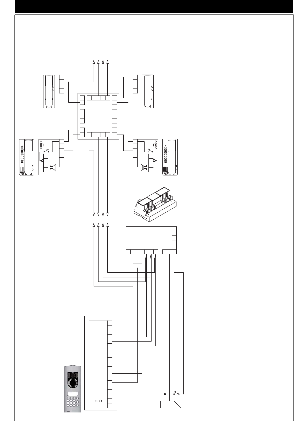
SIMPLE RESIDENTIAL ISTALLATION WITH INTERPHONES EQUIPPED WITH INTERNAL DECODING.
Ref diagram si074.00
INTERPHONE CABLE RISER
5431
Phone
Art. 887B
Art. 887B/1
1
3
4
5
6
Phone
Art. 6204
1
3
4
5
6
12
11
Phone
Art. 887B
Art. 887B/1
1
3
4
5
6
V3
M
V1
13
12
11
10
Phone
9
Art. 6604/AU
8
7
Art. 6704/AU
6
5
4
3
2
1
C- Entrance panel Art. 1284
CX-Entrance panel series 1200
P- Additional push-button for lock
L- Electric lock 12V A.C.
CX
88888888
1
2
5
4
8
7
0
R
5341
M1
C
V2
SR
CH
VL
3
6
*
9
C
J1
M
V1
+I
F1
F2
+L
Mains
PRI
Power supply
Art. 6941
534F1SCH F2
V
1
3
4
5
6
8
R1
4
R2
4
015S1
P
4
L
17
Page 18
WIRING DIAGRAM
SIMPLE RESIDENTIAL INSTALLATION WITH FLOOR DISTRIBUTORS EQUIPPED WITH INTERNAL
DECODING. Ref. diagram si075.00
INTERPHONE
CABLE RISER
1543
1
3
6
7
1
2
3
4
5
6
Phone
Art. 8877
C- Entrance panel Art. 1284
CX-Entrance panel series 1200
P- Additional push-button for lock
L- Electric lock 12V A.C.
Phone
Art. 6201
SR
SDSD
C
A
Phone
Art. 6201
Phone
Art. 8877
SR
C
A
1
3
6
7
A1 21354
A3
Distributor
4
A
Art. 949B
C1
C3
4
C
D
D1
B3B121B354
D3
1
2
3
4
5
6
CX
88888888
1
2
5
4
8
7
0
R
1543
Mains
PRI
Power supply
Art. 6941
F2CH S F1 435
R1
4
R2
4
S1 15 0
M
V
1
3
4
5
6
8
V1
M1
C
V2
SR
+I
CH
VL
P
4
3
6
*
9
C
J1
F1
F2
+L
L
18
Page 19

WIRING DIAGRAM
SIMPLE RESIDENTIAL INSTALLATION WITH TWO OR MORE PANELS IN PARALLEL.
Ref. diagram si076.00
P
PRI
Mains
Relay
Art. 170/001
PRI
Mains
Transformer
Art. M832
Transformer
Art. M832
120
LL
54321
8
6
3
1
4
V
M
5
V1
V2
M1
SR
C
1
3
4
5
CH
CX
4
+I
VL
CH
+L
F2
F1
J1
*
9
6
3
C
8
0
2
5
88888888
1
7
R
4
P
120
L
Relay
Art. 170/001
R1
PRI
Mains
5
4
4
R2
S1 15 0
F2CH S F1 435 12345
Power supply
Art. 6941
8
6
3
1
4
V
M
5
V1
V2
M1
SR
C
CX
4
+I
VL
CH
+L
F2
F1
Disconnect the metal jumper located
on the side of the terminal block.
J1
*
9
6
3
C
8
0
2
5
88888888
1
7
R
4
P
8
6
3
1
4
V
M
5
V1
V2
M1
SR
C
4
+I
VL
CH
+L
F2
F1
J1
134
INTERPHONE
CABLE RISER
CX
3
2
88888888
1
*
9
6
C
0
8
5
7
R
4
C- Entrance panel Art. 1284
CX-Entrance panel series 1200
P- Additional push-button for lock
L- Electric lock 12V A.C.
19
Page 20

WIRING DIAGRAM
RESIDENTIAL INSTALLATION WITH ONE MAIN PANEL AND TWO OR MORE SECONDARY PANELS
(BUILDING COMPLEX). Ref. diagram si077.00
CX
88888888
1
4
7
R
INTERPHONE
CABLE RISER
3
2
6
5
*
9
8
C
0
INTERPHONE
CABLE RISER
5341 1435
Mains
R1
4
R2
4
534F1SCH F2
015S1
CX
C
P
88888888
1
3
2
6
5
4
*
9
8
7
C
0
L L
R
J1
J1
PRI
Power supply
Art. 6941
M
V
1
3
4
5
6
8
V1
M1
C
V2
SR
+I
CH
VL
4
F1
F2
+L
V1
M1
V2
SR
CH
VL
F1
M
V
+I
F2
+L
1
3
4
5
6
8
4
Mains
PRI
Power supply
Art. 6941
F2CH S F1 435
S1 15 0
R1
4
R2
4
P
486
CABLE RISER
6
8
C- Entrance panel Art. 1284
CX-Entrance panel series 1200
P- Additional push-button for lock
L- Electric lock 12V A.C.
Parameters to set:
Parameters to modify on the secondary entrance
panels.
Initial user "INITI_US"
Final user "FINA_US"
The numbers between initial user and final user of
each entrance panel must not be the same as
those of another secondary entrance panel.
Parameters to modify on the main entrance panel.
Chime duration "SOUND_T" The call time of the
main entrance panel must be greater than the call
time of the secondary panels (by at least one second).
143
CX
88888888
1
2
5
4
8
7
0
R
684
CABLE RISER
6
8
44
Mains
S1 15 0
R1
4
R2
4
P
L
PRI
Power supply
Art. 6942
F2CH S F1 435
M
V
1
3
4
5
6
8
V1
M1
C
V2
SR
+I
CH
VL
3
6
*
9
C
J1
4
F1
F2
+L
20
Page 21
WIRING DIAGRAM
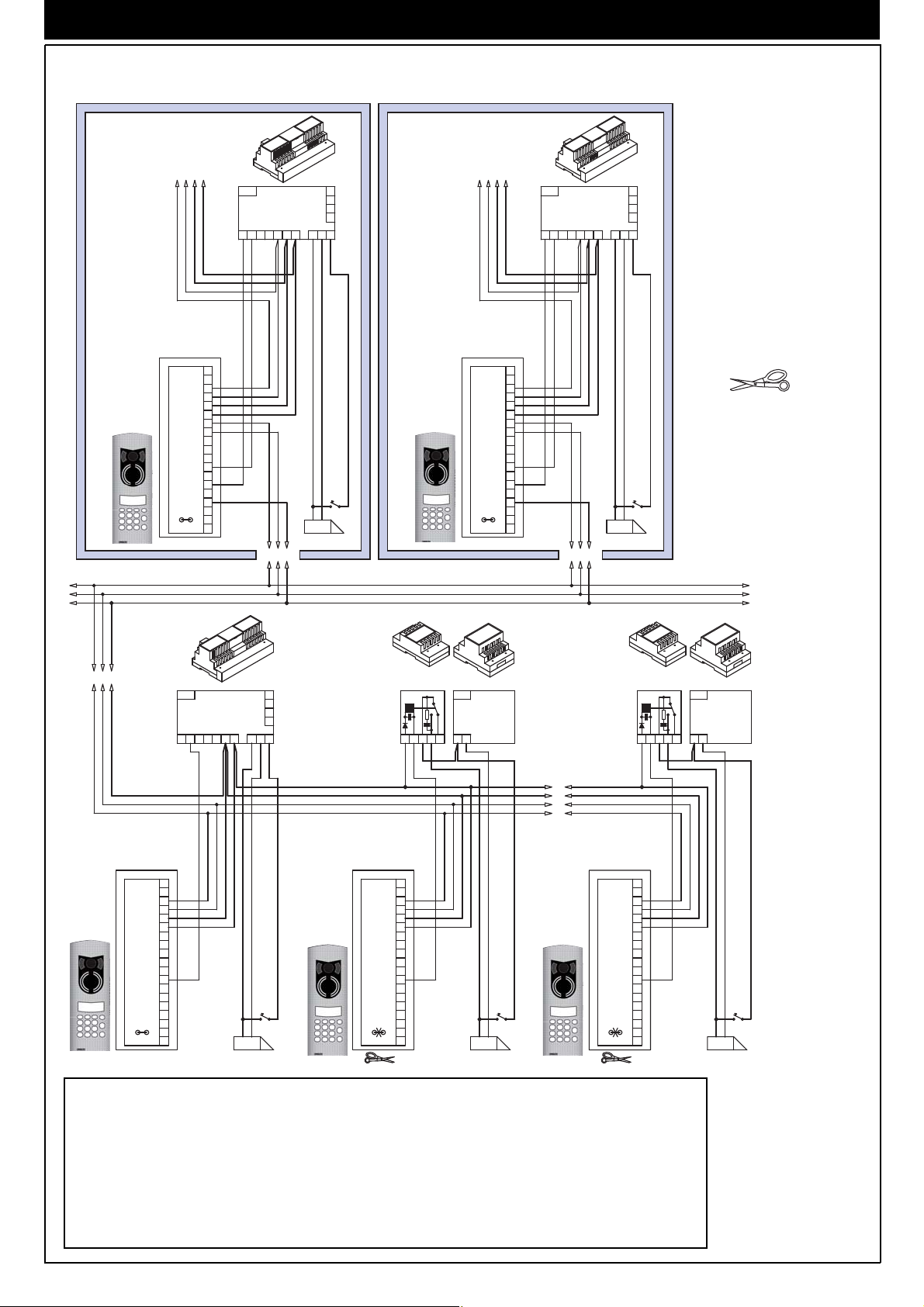
RESIDENTIAL INSTALLATION WITH TWO OR MORE MAIN PANELS AND TWO OR MORE SECONDA-
RY PANELS (BUILDING COMPLEX). Ref. diagram si078.00
CX
88888888
1
3
2
6
5
4
8
9
7
0
C
R
CABLE RISER
6
8
INTERPHONE
CABLE RISER
Mains
5341 1435
M
V
1
3
4
5
6
8
V1
M1
C
V2
SR
+I
CH
VL
4
J1
*
F1
F2
+L
PRI
Power supply
Art. 6941
534F1SCH F2
486
INTERPHONE
CABLE RISER
Mains
R1
4
R2
4
015S1
CX
C
P
L L
88888888
1
4
7
R
3
2
5
8
0
J1
6
*
9
C
M
V
1
3
4
5
6
8
V1
M1
V2
SR
+I
CH
VL
4
F1
F2
+L
PRI
Power supply
Art. 6941
F2CH S F1 435
684
S1 15 0
R1
4
R2
4
Disconnect the
metal jumper
located on the
side of the terminal block.
P
CABLE RISER
6
8
44
5
4
3
1
CX
88888888
1
4
7
R
3
2
6
5
*
8
9
0
C
Relay
Art. 170/001
12345
M
V
1
3
4
5
6
8
V1
M1
C
V2
SR
+I
CH
VL
4
J1
F1
F2
+L
Mains
CX
88888888
1
4
7
R
Mains
431
PRI
Power supply
Art. 6942
M
V
1
3
4
5
6
8
V1
M1
C
V2
SR
+I
CH
VL
3
2
6
5
*
8
9
0
C
4
J1
F1
F2
+L
R1
4
R2
4
015S1
P
L L
CX
1
4
7
R
88888888
2
5
8
0
3
6
*
9
C
Art. 170/001
C
J1
Mains
PRI
120
54321534F1SCH F2
M
V
1
3
4
5
6
8
V1
M1
V2
SR
+I
CH
VL
4
F1
F2
+L
L
Transformer
Art. M832
P
Relay
Parameters to set:
Parameters to modify on the secondary entrance panels.
Initial user "INITI_US"
Final user "FINA_US"
The numbers between initial user and final user of each entrance panel must not be the same as those
of another secondary entrance panel. Parameters to modify on the main entrance panel. Chime duration "SOUND_T" The call time of the main entrance panel must be greater than the call time of the secondary panels (by at least one second).
PRI
Transformer
120
Art. M832
P
C- Entrance panel Art.
1284
CX-Entrance panel
series 1200
P- Additional push-
button for lock
L- Electric lock 12V
A.C.
21
Page 22

WIRING DIAGRAM
MONITOR CABLE RISER WITH UNITS EQUIPPED WITH INTERNAL DIGITAL SIGNAL DECODING.
Ref. diagram si356.00
MONITOR
CABLE RISER
Monitor
Art. 6000 +
Art. 6145 +
Art. 6204
Monitor
Art. 6304
Art. 6304/C
Art. 6504
Art. 6324
Art. 6324/C
Monitor
Art. 6003 +
Art. 6145 +
Art. 6204
CN1
V2
V1
M
V3
13
12
11
10
9
8
7
6
5
4
3
2
1
V1
M
V2
M
V3
+A
+
-
+D
CH
CN2
75ohm
75ohm
1V354
-
+
V3
75ohm
M
V1
13
12
Monitor
11
Art. 6604
10
Art. 6704
9
8
Art. 6614
7
Art. 6714
6
5
4
3
2
1
Monitor
Art. 6003 +
Art. 6145 +
Art. 6204
75ohm
V1
M
V2
M
V3
+A
Monitor
Art. 6000 +
Art. 6145 +
Art. 6204
CN1
+
-
+D
CH
CN2
Distributor
Art. 5556/004 - 5555
MONIT.
1
3
4
5
6
12
11
V4
V3
V2
V1
V
V
-
+
1V543+-
MONIT.
1
3
4
5
6
12
11
TO POWER SUPPLY
ART. 6948
The riser shown must be included in all the
video monitor diagrams in this collection (this
diagram is an alternative to diagram si036)
22
NOTE: The last video distribu-
tor must be loaded with a 75
Ohm resistor connected to free
terminal V.
Page 23

WIRING DIAGRAM
MONITOR RISER WITH FLOOR DISTRIBUTOR ART. 949B
Ref. diagram si036
MONITOR
CABLE RISER
V+-5431
75ohm
V2
V1
M
Monitor
Art. 6307
Art. 6327
Art. 6507
Art. 6307/C
V3
13
12
11
10
9
8
7
6
5
4
3
2
1
75 ohm
M
V
M
V
FP
6P
13
12
11
10
8
7
6
3
1
Monitor
Art. 6607
Art. 660B
Monitor
Art. 6000 +
Art. 6145 +
Art. 6201
Monitor
Art. 6003 +
Art. 6145 +
Art. 6201
V1
M
V2
M
V3
CN1
+A
+
+D
CH
1
2
3
4
SR
5
SD
6
C
A
CN2CN4
A1
A3
4
A
B
B1
75ohm
V4
V3
V2
V1
V
V
-
+
54321
C1
C3
X
4
C
D
D1
54321B3
D3
Monitor
Art. 6000 +
Art. 6145 +
Art. 6201
75ohm
V1
M
V2
M
V3
+A
+
+D
CH
1
2
3
4
5
6
CN2
CN4
Monitor
Art. 6003 +
Art. 6145 +
Art. 6201
CN1
SR
SD
C
A
Distributor
Art. 5556/004 - 5555
X- Distributor Art. 949B
The riser shown must be included in all
the video monitor diagrams in this collection (this diagram is an alternative to
diagram si035)
V+-5431
TO POWER SUPPLY
ART. 6948
NOTE: The last video distributor must be loaded with a 75
Ohm resistor connected to free
terminal V.
23
Page 24

WIRING DIAGRAM
SIMPLE RESIDENTIAL INSTALLATION WITH MONITORS EQUIPPED WITH INTERNAL DECODING.
Ref. diagram si357_1
-
Monitor
Art. 6304
Art. 6304/C
Art. 6504
Art. 6324
Art. 6324/C
1V3 54
75ohm
V2
V1
M
V3
13
12
11
10
9
8
7
6
5
4
3
2
1
+
MONITOR
CABLE RISER
V3
V1
13
12
11
10
M
9
8
7
6
5
4
3
2
1
75ohm
Monitor
Art. 6604
Art. 6704
Art. 6614
Art. 6714
Monitor
Art. 6000 +
Art. 6145 +
Art. 6204
Monitor
Art. 6003 +
Art. 6145 +
Art. 6204
V1
M
V2
M
V3
CN1
+A
+
-
+D
CH
CN2
MONIT.
1
3
4
5
6
12
11
V4
V3
V2
V1
V
V
-
+
VIDEO DISTRIBUTOR
Art. 5556/004
Art. 5555
75ohm
1V543+-
75ohm
MAINS
PRI
V1
M
V2
M
V3
CN1
+A
+
-
+D
CH
CN2
MONIT.
1
3
4
5
6
12
11
POWER SUPPLY
Art. 6948
CHSF1F2345+ 15O
+I
Monitor
Art. 6000 +
Art. 6145 +
Art. 6204
R1
4
R2
4
-
S1M1V1V2M2
Monitor
Art. 6003 +
Art. 6145 +
Art. 6204
NOTE: The last video distributor must be loaded with a 75
Ohm resistor connected to free
terminal V.
D- Entrance panel Art. 1287
DX- Entrance panel series 1200
P- Additional push-button for lock
L- Electric lock 12V A.C.
24
DX
88888888
1
4
7
R
M
V
1
3
4
5
6
8
V1
M1
D
V2
SR
+I
CH
VL
3
2
6
5
*
9
8
C
0
4
J1
F1
F2
+L
V
1
3
4
5
SR
+I
CH
P
L
Page 25

WIRING DIAGRAM
SIMPLE RESIDENTIAL INSTALLATION WITH DISTRIBUTORS EQUIPPED WITH INTERNAL DECODING. Ref. diagram si080.00
Monitor cable riser
1345- +V
75 ohm
75ohm
M
V
M
V
FP
Monitor
6P
Art. 6607
13
12
Art. 660B
11
10
8
7
6
3
1
Monitor
Art. 6000 +
Art. 6145 +
Art. 6201
V1
M
V2
M
V3
CN1
+A
+
-
+D
CH
CN2
Monitor
Art. 6003 +
Art. 6145 +
Art. 6201
Monitor
Art. 6307
Art. 6327
Art. 6507
Art. 6307/C
Monitor
Art. 6003 +
Art. 6145 +
Art. 6201
V2
V1
M
V3
13
12
11
10
9
8
7
6
5
4
3
2
1
Monitor
Art. 6000 +
Art. 6145 +
Art. 6201
V1
M
V2
M
V3
CN1
+A
+
+D
CH
75ohm
75ohm
X
C1
C3
4
C
D
D1
D3
12345
A1
A3
4
A
B
B1
B3 12345
CN4 CN2
1
2
3
4
SR
5
SD
6
C
A
V4
V3
V2
V1
V
V
-
+
VIDEO DISTRIBUTOR
Art. 5556/004
Art. 5555
NOTE: The last video distributor must
be loaded with a 75 Ohm resistor connected to free terminal V.
CN4
1
2
3
4
SR
5
SD
6
C
A
1345- +V
MAINS
PRI
POWER SUPPLY
Art. 6948
M2 V2 V1 M1 S1
+I
R1
4
R2
4
O15+543F2F1SCH
-
D- Entrance panel Art. 1287
DX- Entrance panel series 1200
P- Additional push-button for lock
L- Electric lock 12V A.C.
X- Distributor 949B
DX
88888888
1
4
7
R
M
V
1
3
4
5
6
8
V1
M1
D
V2
SR
+I
CH
VL
3
2
6
5
*
8
9
0
C
4
F1
J1
F2
+L
P
L
25
Page 26

WIRING DIAGRAM
SIMPLE RESIDENTIAL INSTALLATION WITH TWO OR MORE PANELS IN PARALLEL
Ref. diagram si081.00
P
PRI
Mains
Relay
Art. 170/001
PRI
Mains
120
Transformer
Art. M832
54321
4R14
R2
15S1 0
3F2 4 5
F1SCH
Power supply
Art. 6942
412 335533214
M
V1
V2
M1
8
6
3
1
4
5
V
D
5
143
V
CH
+I
DX
SR
4
+I
CH
+L
F2
F1
VL
J1
*
9
6
3
C
8
0
2
5
88888888
1
7
R
4
LL
Disconnect the metal jumper located on
the side of the terminal block.
Relay
Art. 170/051
R1
PRI
Mains
4R24
O15+543F2F1SCH
Power supply
Art. 6948
M2 V2 V1 M1 S1-+I
8
M
V1
V2
M1
6
4
3
1
5
V
D
DX
SR
4
+I
CH
+L
F2
F1
VL
J1
*
9
6
3
C
8
0
2
5
88888888
1
7
R
4
PP
L
8
M
V1
V2
M1
6
4
3
1
5
V
D
SR
4
+I
CH
+L
F2
F1
VL
J1
26
Relay
Art. 170/051
+-31V54
MONITOR
CABLE RISER
DX
3
2
88888888
1
D- Entrance panel Art. 1287
DX- Entrance panel series 1200
P- Additional push-button for lock
*
9
6
C
8
0
5
7
R
4
L- Electric lock 12V A.C.
Page 27

WIRING DIAGRAM
A
J
T
RESIDENTIAL INSTALLATION WITH ONE MAIN PANEL AND TWO OR MORE STAIRWAY
PANELS (BUILDING COMPLEX). Ref. diagram si083.00
MONITOR CABLE RISER
+-31V54
CX
C
88888888
1
3
2
6
5
4
9
8
7
C
0
R
J1
*
PRI
M2 V2 V1 M1 S1-+I
M
V
1
3
4
5
6
8
V1
M1
V2
SR
+I
CH
VL
4
F1
F2
+L
Power supply
Art. 6948
MONITOR CABLE RISER
45V13 - +
R1
4
R2
4
O15+543F2F1SCH
CX
88888888
1
3
2
6
5
4
*
9
8
7
C
0
L
R
MainsMains
PRI
Power supply
Art. 6948
CHSF1F2345+ 15O
+I - S1M1V1V2M2
M
V
1
3
4
5
6
8
V1
M1
C
V2
SR
+I
CH
VL
4
F1
J1
F2
+L
L
R1
4
R2
4
PP
Cable riser
V
6
8
4
C- Entrance panel Art. 1284
CX- Entrance panel series 1200
D- Entrance panel Art. 1287
DX- Entrance panel series 1200
P- Additional push-button for lock
L- Electric lock 12V A.C.
Parameters to set:
Parameters to modify on the secondary entrance panels.
Initial user "INITI_US" Final user "FINA_US".
The numbers between initial user and final user of each
entrance panel must not be the same as those of another secondary entrance panel.
Parameters to modify on the main entrance panel.
Chime duration "SOUND_T". The call time of the main
entrance panel must be greater than the call time of the
secondary panels (by at least one second).
Distributor
Art. 5556/004
VVVV431
75ohm
Cable riser
V
6
8
4
DX
88888888
1
4
7
R
2
5
8
0
Mains
3
6
*
9
C
PRI
Power supply
Art. 6582
+U-+I
M
V
1
3
4
5
6
8
V1
M1
D
V2
SR
+I
CH
VL
4
F1
J1
F2
+L
Mains
CH S F1DCBA
PRI
Power supply
Art. 6942
R1
4
R2
4
0S1 15
54F2 3
P
L
V4
V3
V2
V1
V
V
-
+
27
Page 28
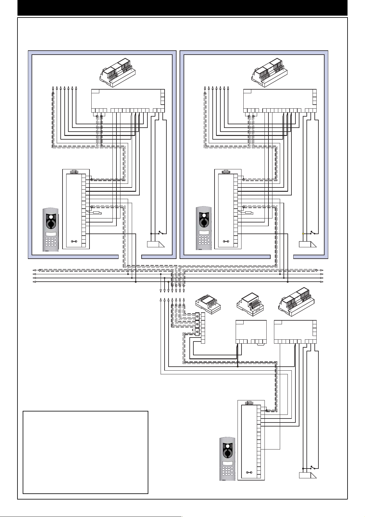
WIRING DIAGRAM
RESIDENTIAL INSTALLATION WITH ONE MAIN PANEL AND TWO OR MORE STAIRWAY
PANELS (BUILDING COMPLEX). Ref. diagram si082.00
MONITOR
CABLE RISER
DX
88888888
1
3
2
6
5
4
*
8
9
7
0
C
R
MONITOR
CABLE RISER
+-31V54
Mains
PRI
Power supply
Art. 6948
M2 V2 V1 M1 S1-+I
M
V
1
3
4
5
6
8
V1
M1
D
V2
SR
+I
CH
VL
4
J1
F1
F2
+L
L
R1
4
R2
4
O15+543F2F1SCH
P
DX
88888888
1
4
7
R
45V13 - +
3
2
6
5
*
8
9
0
C
Mains
PRI
Power supply
Art. 6948
+I - S1M1V1V2M2
CH S F1 F2 3 4 5 + 15 O
M
V
1
3
4
5
6
8
V1
75 Ohm75 Ohm
M1
D
V2
SR
+I
CH
VL
4
J1
F1
F2
+L
L
R1
4
R2
4
P
Cable riser
V
6
8
4
C- Entrance panel Art. 1284
CX- Entrance panel series 1200
D- Entrance panel Art. 1287
DX- Entrance panel series 1200
P- Additional push-button for lock
L- Electric lock 12V A.C.
Parameters to set:
Parameters to modify on the secondary entrance
panels. Initial user "INITI_US"
Final user "FINA_US" The numbers between initial
user and final user of each entrance panel must
not be the same as those of another secondary
entrance panel.
Parameters to modify on the main entrance panel.
Chime duration "SOUND_T".
The call time of the main entrance panel must be
greater than the call time of the secondary panels
(by at least one second).
VVVV431
75ohm
Distributor
Art. 5556/004
V4
V3
V2
V1
V
V
+
Mains
DX
Art. 8847/C
88888888
1
3
2
6
5
4
*
9
8
7
0
C
R
PRI
Power supply
Art. 6582
+U-+I
M
V1
M1
D
V2
SR
+I
CH
VL
F1
J1
F2
+L
Cable riser
V
6
8
4
Mains
PRI
Power supply
Art. 6942
CH S F1DCBA
V
1
3
4
5
6
8
4
L
R1
4
R2
4
0S1 15
54F2 3
P
28
Page 29

WIRING DIAGRAM
RESIDENTIAL INSTALLATION WITH TWO OR MORE MAIN VIDEO PANELS AND TWO OR MORE
VIDEO OR AUDIO STAIRWAY PANELS (BUILDING COMPLEX) REF. DIAGRAM SI084.00
Cable Riser
V
6
8
4
MONITOR
CABLE RISER
DX
88888888
1
4
7
R
2
5
8
0
VVVV431
D
3
J1
6
*
9
C
+-31V54
Mains
M
V
1
3
4
5
6
8
V1
M1
V2
SR
+I
CH
VL
4
F1
F2
+L
PRI
M2 V2 V1 M1 S1-+I
Power supply
Art. 6948
MONITOR
CABLE RISER
45V13 - +
R1
4
R2
4
O15+543F2F1SCH
DX
88888888
1
3
2
6
5
4
*
8
9
7
0
C
L
R
Mains
PRI
Power supply
Art. 6948
+I - S1M1V1V2M2
CH S F1 F2 3 4 5 + 15 O
M
V
1
3
4
5
6
8
V1
75 Ohm75 Ohm
M1
D
V2
SR
+I
CH
VL
4
J1
F1
F2
+L
R1
4
R2
4
Disconnect the metal
jumper located on the
side of the handset
cable riser terminal
PP
L
board.
Cable Riser
V
6
8
4
Transformer
Art. M832
Relay
Art. 170/051
75ohm
Mains
V4
PRI
V3
Power supply
V2
V1
Art. 6582
V
V
+
+U-+I
Distributor
Art. 5556/004
DX
88888888
1
3
2
6
5
4
*
9
8
7
C
0
R
D- Entrance panel Art. 1287
DX- Entrance panel series 1200
P- Additional push-button for lock
L- Electric lock 12V A.C.
Relay
Mains
PRI
Power supply
Art. 6942
CH S F1DCBA
M
V
1
3
4
5
6
8
V1
M1
D
V2
SR
+I
CH
VL
4
F1
J1
F2
+L
R1
4
4
0S1 15R254F2 3
PP
L
Art. 170/051
DX
88888888
1
3
2
6
5
4
*
9
8
7
C
0
R
213354 12345 54321453312
D
J1
Relay
Art. 170/001
M
V
1
3
4
5
6
8
V1
M1
V2
SR
+I
CH
VL
4
F1
F2
+L
Mains
PRI
Transformer
Art. M832
120
DX
88888888
1
4
7
LL
R
2
5
8
0
V
5
4
3
1
3
6
*
9
C
Relay
Art. 170/001
M
V
1
3
4
5
6
8
V1
M1
D
V2
SR
+I
CH
VL
4
F1
J1
F2
+L
Mains
PRI
120
P
Parameters to modify on stairway panels
Initial User UT INI, Final User UT FIN
Numbers between the initial user and final user of each panel must not coicide with those of another stairway panel.
Parameters to modify on the main entrance panel
Chime duration T suono
The call time of the main panel must be greater than the call time of the stairway panels (by at least one second)
29
Page 30

WIRING DIAGRAM
VARIANTS si085
During programming of the entrance panel it is possible to change the following two parameters:
22 T_F1 Function time F1 Activation time of 1st auxiliary function F1
23 T_F2 Function time F2 Activation time of 2nd auxiliary function F2
Connection of auxiliary functions F1 - F2 in systems equipped with internal decoding or without internal decoding.
In some cases, enabling the functions requires the use of supplementary buttons and connections to be made in addition to the
basic connections. Interphones type 6204 and 6201 are fitted as standard with only the lock release button; for the use of a second auxiliary function, it is necessary to add button art. 6152 (pack containing 8 N.O. push-button in intephones type 6201 and type
6C59 (pair of N.O. push-buttons) in interphones type 6204. It is possible to activate an auxiliary function F1 controlled by the interphones or monitors by connecting a relay Art. 170/001 as shown in the diagram (terminals R1-4 of the power supply). It is possible to activate an auxiliary function F2 controlled by the interphones or monitors by connecting a relay Art. 170/001 as shown in
the diagram (terminals R2-4 of the power supply unit).
The buttons "F1" and activate the function F1. The buttons "F2" and activate function F2.
Interphones with internal coding
INTERPHONE
CABLE RISER
5431
Phone
Art. 8877
1
3
4
5
6
1
3
4
5
6
Phone
Art. 6204
1
3
4
5
6
12
11
TO POWER SUPPLY
ART. 6948
1435
V3
M
V1
13
12
Phone
11
10
Art. 6604/AU
9
8
Art. 6704/AU
7
6
5
4
3
2
1
Connection of
relays for additional functions
Phone
Art. 8877
INTERPHONE
CABLE RISER
Interphones without
internal coding
Phone
Art. 887B
Art. 887B/1
Phone
Art. 6201
5341
Mains
PRI
Power supply
Art. 6941
F2CH S F1 435
INTERPHONE
CABLE RISER
3451
1
3
6
7
A3
4
A
B1
B3
1
2
3
4
SR
5
SD SD
6
C
A
C1
45312A1
C3
4
A
C
D
D1
D3
453B12
TO POWER SUPPLY
S1 15 0
ART. 6948
R1
4
R2
4
Relay
Art. 170/001
3451
Relay
Art. 170/001
1234554321
1
3
6
7
Phone
Art. 887B
Art. 887B/1
Phone
Art. 6201
1
2
3
4
SR
5
6
C
A
A- Distributor 949B
30
CX
88888888
1
4
7
R
CNONOC
Additional function
F1
M
V
1
3
4
5
6
8
V1
M1
C
V2
SR
+I
CH
VL
3
2
6
5
*
9
8
C
0
4
F1
J1
F2
+L
C- Entrance panel Art. 1284
CX- Entrance panel series 1200
P
L
Additional function
F2
Page 31

WIRING DIAGRAM
VARIANTS si086
During programming of the entrance panel it is possible to change the following two parameters:
22 T_F1 Function time F1 Activation time of 1st auxiliary function F1
23 T_F2 Function time F2 Activation time of 2nd auxiliary function F2
Connection of auxiliary functions F1 - F2 in systems equipped with internal decoding or without internal decoding.
In some cases, enabling the functions requires the use of supplementary buttons and connections to be made in addition to the
basic connections. Interphones type 6204 and 6201 are fitted as standard with only the lock release button; for the use of a second auxiliary function, it is necessary to add button art. 6152 (pack containing 8 N.O. push-button in intephones type 6201 and type
6C59 (pair of N.O. push-buttons) in interphones type 6204. It is possible to activate an auxiliary function F1 controlled by the interphones or monitors by connecting a relay Art. 170/001 as shown in the diagram (terminals R1-4 of the power supply). It is possible to activate an auxiliary function F2 controlled by the interphones or monitors by connecting a relay Art. 170/001 as shown in
the diagram (terminals R2-4 of the power supply unit).
The buttons "F1" and activate the function F1. The buttons "F2" and activate function F2.
Monitors without internal coding
MONITOR
CABLE RISER
1345 -+V
Monitor
Art. 6307
Art. 6307/C
Art. 6507
Art. 6327
Monitor
Art. 6607
Art. 660B
DX
88888888
1
2
5
4
8
7
0
R
75 ohm
M
V
M
V
FP
6P
13
12
11
10
8
7
6
3
1
75ohm
V2
V1
M
V3
13
12
11
10
9
8
7
6
5
4
3
2
1
A1
12345
A3
4
A
B
B1
B3 12345
C1
C3
4
A
C
D
D1
D3
1345 -+V
Mains
PRI
PRI
Power supply
Art. 6948
M
V
1
3
4
5
6
8
V1
M1
D
V2
SR
+I
CH
VL
4
J1
3
6
*
9
C
F1
F2
+L
75ohm
V1
V2
V3
+A
+D
CH
M
M
+
1
2
3
4
5
6
4
8
4
9
S1
-
CN2
CN4
CN1
SR
SD
Monitor
Art. 6000+
Art. 6201+
Art. 6145+
Art. 6152
C
A
Monitor
Art. 6003+
Art. 6201+
Art. 6145+
Art. 6152
A- Distributor 949B
Relais
Art. 170/001
R1
4
R2
4
O15--+435F2SF1F1CH+IM1V1M2 V2
O15+435F2SCH+IM1V1M2 V2
12345 54321
Additional
function F1
Relais
Art. 170/001
CNO NOC
MAX 3A 230V MAX 3A 230V
Additional
function F2
D- Entrance panel Art. 1287
DX- Entrance panel series 1200
31
Page 32

Monitors with internal coding
75ohm
Monitor
Art. 6604
Art. 6614
Monitor
Art. 6304
Art. 6304/C
Art. 6504
Art. 6324
Art. 6324/C
WIRING DIAGRAM
MONITOR
CABLE RISER
+5-4311
V3
M
V1
13
12
11
10
9
8
7
6
5
4
3
2
1
V2
75ohm
V1
M
V3
13
12
11
10
9
8
7
6
5
4
3
2
1
+-5341V
75ohm
V1
M
CH
V2
M
V3
+A
CN1
+
-
+D
Monitor
Art. 6000 +
Art. 6145 +
Art. 6204 +
Art. 6C59
Monitor
Art. 6003 +
Art. 6145 +
Art. 6204 +
Art. 6C59
CN2
MONIT
1
3
A
4
5
6
11
12
C
F1
T2
F2
T1
Art. 6C59
1
3
A
4
5
6
11
12
C
F1
F1
T2
F2
F2
T1
Art. 6C59
Phone
Art. 6204 +
Art. 6C59
D- Entrance panel Art. 1287
DX- Entrance panel series 1200
DX
88888888
1
4
7
R
Mains
PRI
PRI
Power supply
Art. 6948
M
V
1
3
4
5
6
8
V1
M1
D
V2
SR
+I
CH
VL
3
2
6
5
*
8
9
0
C
4
J1
F1
F2
+L
R1
4
R2
4
O1515-+435F2SF1CH+IM1V1M2 V2
S1
O-+435F2SF1CH+IM1V1M2 V2
Relais
Art. 170/001
12345 54321
Additional
function F1
Relais
Art. 170/001
CNO NOC
MAX 3A 230V MAX 3A 230V
Additional
function F2
32
Page 33

WIRING DIAGRAM
VARIANTS si087
During programming of the entrance panel it is possible to change the following two parameters:
22 T_F1 Function time F1 Activation time of 1st auxiliary function F1
23 T_F2 Function time F2 Activation time of 2nd auxiliary function F2
Variation for additional modules type 805N-80PN
Wiring diagram for connection of Digibus sytem electronic entrance panel with keypad and additional
numerical display with luminous name-tag for 13 names type 805N or for street number type 80PN.
CX
88888888
1
2
5
4
8
7
0
R
TO POWER SUPPLY
ART. 6941
SR
CH 4
M
V
1
3
4
5
6
8
V1
M1
C
V2
SR
+I
CH
VL
3
6
9
C
J1
4
F1
F2
+L
53
1
M
V
1
3
4
5
6
8
DX
V1
M1
D
V2
SR
+I
CH
J1
VL
4
F1
F2
+L
88888888
1
2
5
4
8
7
0
R
3
6
**
9
C
TO POWER SUPPLY
ART. 6948
35
SR+I
1
V
4CH
+
C- Entrance panel Art. 1284
CX- Entrance panel series 1200
D- Entrance panel Art. 1287
DX- Entrance panel series 1200
-
E4E4
+
33
Page 34

WIRING DIAGRAM
J
J
VARIANTS
A
Variation for self-protection of the digital line
with interruption of the riser only.
Ref.diagram si555
INTERPHONE CABLE RISER
Mains
5341
PRI
Power supply
Art. 6941
534F1SCH F2
R1
4
R2
4
015S1
VARIANTS B
Variation for self-protection of the digital line
with interruptions of the riser and the same
entrance panel. Ref.diagram si555
INTERPHONE CABLE RISER
5341
Mains
PRI
Power supply
Art. 6941
534F1SCH F2
R1
4
R2
4
015S1
M
V
1
3
4
5
6
CX
8
V1
M1
C
V2
SR
+I
CH
VL
88888888
1
2
5
4
8
7
0
R
3
6
*
9
C
J1
4
F1
F2
+L
C- Entrance panel Art. 1284
CX- Entrance panel series 1200
P- Additional push-button for lock
L- Electric lock 12V A.C.
M
V
1
3
4
5
6
8
CX
V1
M1
C
V2
SR
+I
CH
J1
VL
4
F1
F2
+L
P
88888888
1
2
5
4
8
7
0
R
3
6
*
9
C
L
P
L
C- Entrance panel Art. 1284
CX- Entrance panel series 1200
P- Additional push-button for lock
L- Electric lock 12V A.C.
34
Standard connection
Connection for variations
Standard connection
Connection for variations
Page 35

L
WIRING DIAGRAM
VARIANTS
C
Variation for self-protection of the digital line
with interruption of the monitor cable riser only.
Ref. diagram si556
MONITOR
CABLE RISER
1V543+-
Mains
PRI
Power supply
Art. 6948
+I
CHSF1F2345+ 15O
-
R1
4
R2
4
S1M1V1V2M2
VARIANTS D
Variation for self-protection of the digital line
with interruptions of the monitor cable riser and
the same entrance panel
MONITOR
CABLE RISER
1V543+-
. Ref. diagram si556
Mains
PRI
Power supply
Art. 6948
+I
CHSF1F2345+ 15O
R1
4
R2
4
-
S1M1V1V2M2
M
V
1
3
4
J1
5
6
8
V1
M1
D
V2
SR
+I
CH
VL
4
F1
F2
+L
DX
88888888
1
4
7
R
3
2
6
5
*
8
9
0
C
D- Entrance panel Art. 1287
DX- Entrance panel series 1200
P- Additional push-button for lock
L- Electric lock 12V A.C.
DX
D
P
88888888
1
3
2
6
5
4
*
9
8
7
C
0
R
J1
D- Entrance panel Art. 1287
DX- Entrance panel series 1200
P- Additional push-button for lock
L- Electric lock 12V A.C.
M
V
1
3
4
5
6
8
V1
M1
V2
SR
+I
CH
VL
4
F1
F2
+L
P
L
Standard connection
Connection for variations
Standard connection
Connection for variations
35
Page 36

SAFETY INSTRUCTIONS FOR INSTALLERS
- Carefully read the instructions on this leaflet: they provide important information on the safety, use and maintenance of the installation.
- After removing the packing, check the integrity of the set. Packing components (plastic bags, expanded polystyrene etc.) are dangerous for children. Installation must be carried out according to national safety regulations.
- ATTENTION: to avoid physical injury, himself, this appliance must be fixed to the ground/wall according to the installation instructions.
- A bipolar switch with 3 mm gap (minimum) between contacts should be fitted in an accessible location near the power supply line
- It is convenient to fit close to the supply voltage source a proper bipolar easy accessible type switch with 3 mm separation (minimum) between contacts.
- Before connecting the set, ensure that the data on the label correspond to those of the mains.
- Use this set only for the purposes designed, i.e.for electric door-opener systems. Any other use may be dangerous. The manufacturer is not responsible for damage caused by improper, erroneous or irrational use.
- Before cleaning or maintenance, disconnect the set.
- In case of failure or faulty operation, disconnect the set and do not open it.
- For repairs contact exclusively the technical assistance centre authorized by the manufacturer.
- Safety may be compromised if these instructions are disregarded.
- Do not obstruct opening of ventilation or heat exit slots and do not expose the set to dripping or water drops or sprays.
- Installers must ensure that manuals with the above instructions are left on connected units after installation, for users' consultation.
- All items must only be used for the purposes specified.
- This leaflet must always be enclosed with the equipment.
Directive 2002/96/EC (WEEE)
The crossed-out wheelie bin symbol marked on the product indicates that at the end of its useful life, the product must be handled
separately from household refuse and must therefore be assigned to a differentiated collection centre for electrical and electronic
equipment or returned to the dealer upon purchase of a new, equivalent item of equipment.
The user is responsible for assigning the equipment, at the end of its life, to the appropriate collection facilities.
Suitable differentiated collection, for the purpose of subsequent recycling of decommissioned equipment and environmentally compatible treatment and disposal, helps prevent potential negative effects on health and the environment and promotes the recycling
of the materials of which the product is made. For further details regarding the collection systems available, contact your local waste
disposal service or the shop from which the equipment was purchased.
Risks connected to substances considered as dangerous (WEEE).
According to the WEEE Directive, substances since long usually used on electric and electronic appliances are considered dangerous for people and the environment. The adequate differentiated collection for the subsequent dispatch of the appliance for the
recycling, treatment and dismantling (compatible with the environment) help to avoid possible negative effects on the environment
and health and promote the recycling of material with which the product is compound.
36
UNI EN ISO 9001
ELVOX COSTRUZIONI
ELETTRONICHE S.p.A.
35011 Campodarsego (PD) - ITALY
Via Pontarola, 14/A
Tel. 049/9202511 r.a. -
Phone international... 39/49/9202511
Telefax Italia 049/9202603
Telefax Export Dept... 39/49/9202601
ELVOX INTERNET SERVICE
E-mail: info@elvoxonline.it
http://www.elvox.com
E-mail export dept:
elvoxexp@elvoxonline.it
FILIALE DI MILANO:
Via Conti Biglia, 2 20162 (MILANO)
Tel. 02/6473360-6473561
Fax 02/6473733
E-mail: filialemilano@elvoxonline.it
FILIALE TOSCANA:
Via Lunga 4/R 50142 FIRENZE
Tel. 055/7322870 - Telefax. 055/7322670
E-mail: filialetoscana@elvoxonline.it
 Loading...