

Page 1
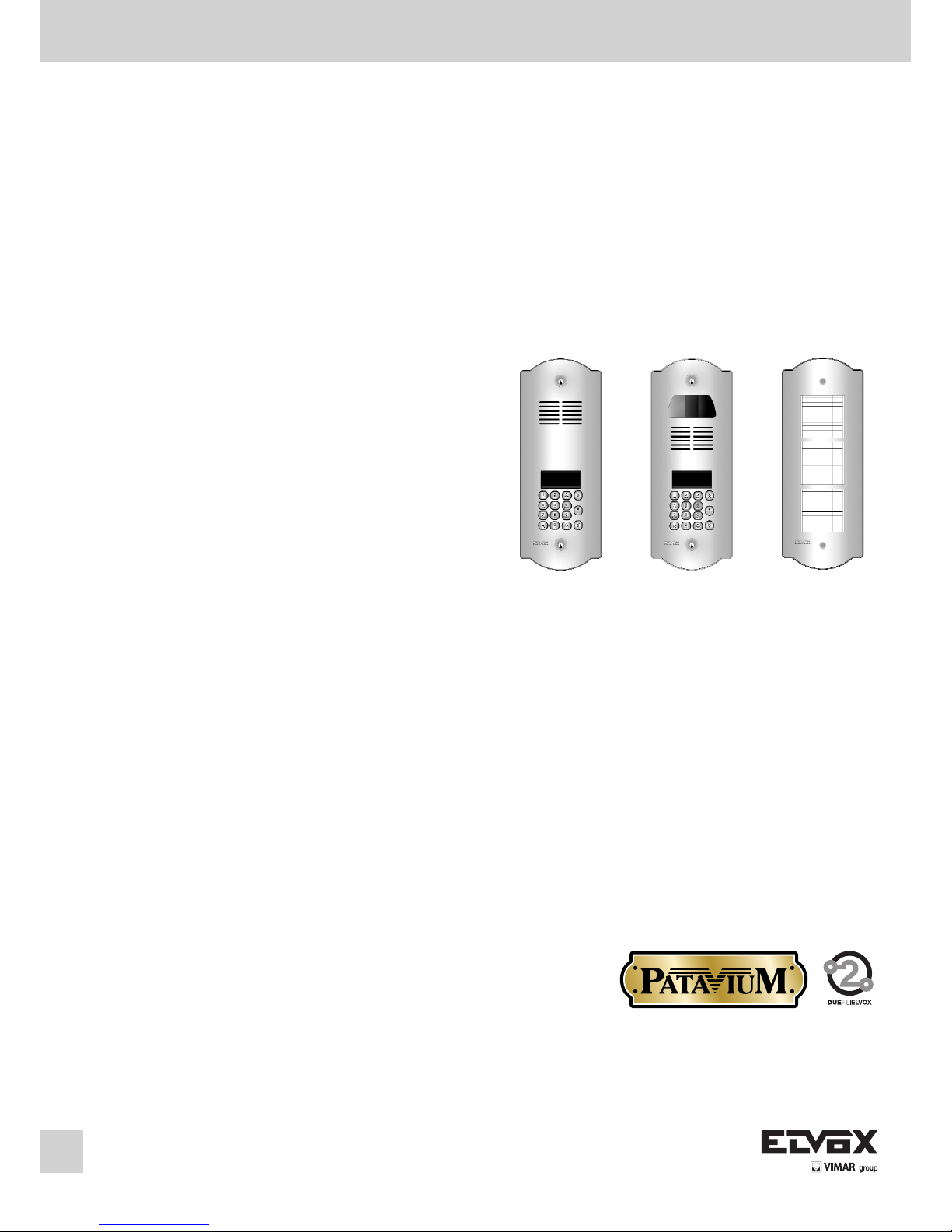
ART. 89F4/T (alphanumeric audio entrance panel)
ART. 89F7/CT (alphanumeric colour video entrance panel)
ART. 805N/T (additional entrance panel)
Audio and video elvox 2-Wire system with entrance panels
series Patavium keypad and numerical display
Installation and operation manual
®
ART. 89F4/T
ART. 89F4/CT
ART. 805N/T
Page 2

2
I
INTRODUCTION
The PATAVIUM serie TWO WIRE ELVOX electronic entrance panels consist of the following parts:
- 1 brass plate with gold-plating and varnishing using the titanium nitride PVD technique.
- 1 flush-mounted back box in zinc plated plate.
- 1 electronic unit with microcontroller.
The following entrance panel models to be configured:
- Audio entrance panel with electronic agenda, alphanumeric
keypad and display, with standard modules type 89F4/T...
- Video entrance panel with colour camera, electronic agenda,
alphanumeric keypad and display, with standard modules type
89F7/CT.
All entrance panels are supplied with the “Engaged-Please Wait”
message, while entrance panels with display have an alphanumeric display with 2 lines x 16 characters and an electronic name
index for up to 400 users. Each user can be associated with two
names comprising max. 16 characters.
An external CCTV type camera can be connected to an audio
entrance panel 89F4 or 89F3, after re-configurating the panel as
video as described in paragraph “Hardware programming – Entrance panel programming modification”.
The entrance panel can be programmed with the entrance panel
keypad or with programming module Type 950C or the PC Software SaveProg Type 69CD, in this case it is necessary to have
the interfaces Type 692I or Type 692I/U.
BASIC ENTRANCE PANELS
The basic entrance panels consist of: 1 electronic unit, 1 connecting terminal block and 1 PATAVIUM series brass entrance
panel. The electronic unit is equipped with: 1 speech unit, 1 camera for the video versions, 1 back-lit alphanumeric display, 1
keypad and 1 cabling for the terminal block connection. The
standard modules for video panels in B/W are equipped with a
b/w camera with ¼" CCD sensor and fixed 3 mm lens and LED
for infrared lighting. The standard modules for video panels in
colour are equipped with a b/w camera with ¼" CCD sensor and
fixed 3 mm lens and white indicator LED. All panels with cameras can be tilted manually, horizontally or vertically, on removal of
the plate. Example of standard module with camera.
3
2
1
1 2 3
4 5 6
7 8 9
0
ABC DEF
GHI JKL MNO
PQRS TUV WXYZ
+
R
Fig. 1
Fig. 2
3
2
1
Controls:
2 – Reset
3 - Balance
Wiring for terminal block connection
Manual horizontal and vertical tilt
Electronic unit
Plate series PATAVIUM
B2
B1
EXT+
EXT-
VLED
M
PA
CA
M
S+
S-
+12V
-L
SR
F2
F1
M
X
B2
B1
EXT+
EXT-
VLED
M
PA
CA
M
S+
S-
+12V
-L
SR
F2
F1
M
X
CN2
CN1
CS2411 250105
Terminal block
CN1) Connector for electronic unit.
CN2) Connector for programmer Type 950C.
B2) 2-wire Bus (cable riser).
B1) 2-wire Bus (cable riser).
EXT+) External power supply (+ type 6923).
EXT-) External power supply (- type 6923).
VLED) LED power supply for additional modules.
X) Video input (coaxial core), for external ca-
mera (for type 89F8 only).
M) Video input (coaxial sheath), for external
camera (for type 89F8 only).
PA) Input for door open sensor (with reference
to terminal M).
CA) Door open command (with reference to
terminal M).
M) Ground.
S+) 12Vdc lock output (+).
S-) 12Vdc lock output (-).
+12V) +12V output (max 100 mA) with PTC pro-
tection.
-L) External camera pilot, open collector out-
put.
SR) Lock pilot via relay, open collector output.
F2) F2 function pilot via relay, open collector
output.
F1) F1 function pilot via relay, open collector
output.
M) Ground.
)
*
*
The panel supplies a current peak IT> 1A for 10
mS, followed by a hold current I
M
= 200mA for
the entire duration of the lock command (see
lock time).
Page 3
I
3
Fig. 4
Fig. A
Fig. B
Fig. C
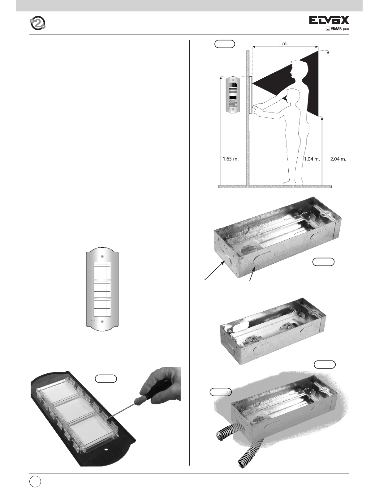
Points to be chosen for the cable to get through. To remove
with a screwdriver.
To reach the name-tags operate on the additional panel rear side
as indicated in figure.
ART. 805N/T
Fig. 3
ADDITIONAL ENTRANCE PANELS
It possible to place side by side of the electronic basic entrance
panels one or more additional entrance panels and precisely type
805N/T for the basic entrance panels type 89F4/T, 89F7/T,
89F7/CT.
INSTALLATION OF THE ENTRANCE PANEL
The installation of the basic entrance panel requires the use of
the flush-mounted back box placed inside the package.
Installation
- Install the back boxes at approx. 1,65 m high from the back
box upper side to the soil (Fig. 4).
- Fit the back box inside the wall making the tubes for the cable
pass through the holes, see sequence Fig. A, Fig. B, Fig. C.
- If the installation requires the coupling of more back boxes,
use the proper separator brackets to fix the boxes among
them (Fig. 5).
- Connect the terminal block of the electronic unit to the terminal block by means of the cabling present on the upper side
(Fig. 6).
- Insert the microphone in proper seat placed on the rear side of
the brass entrance panel (Fig. 7).
- Close the entrance panel paying attention that the electronic of
same adheres perfectly to the brass plate allowing the pushbuttons to be activated until the run end. Should this not be
possible, adjust the screw inside the flush-mounted back box,
thus allowing the electronic unit to adhere to the brass plate
(Fig. 8).
- Close the entrance panel by using the proper door lock blocks
(Fig. 9)
- Carry out the programming phases.
Page 4

I
4
Fig. 7
Fig. 8
Fig. 9
Fig. 5
Fig. 6
Page 5
5
I
PRELIMINARY OPERATIONS
The entrance panel is supplied already with a standard configuration, to be
modified in the case of multiple entrance panels in the same system and
if the user wishes to change the entrance panel operating parameters.
There are three possible types of programming:
- Programming of the parameters listed below, so as to configure the entrance panel according to system requirements.
- Hardware programming, which changes the standard specifications of
the entrance panel and should only be done for special situations.
- Sequential encoding, for programming the identification code of the interphones/monitor interphones via the entrance panel.
The entrance panel can be programmed with the entrance panel keypad
or with programming module Type 950C or the PC Software SaveProg
Type 69CD, in this case it is necessary to have the interfaces Type 692I
or Type 692I/U.
Parameters for programming:
- Parameter Default value
- Message language English
- Entrance panel ID
- Type code Sequential
- Lock code R+1
- Push-button preferential code No association
- Push-button preferential code No association
- Lock passwords No association
- Device numbering No association
- Search the entire agenda No
- Device names No association
- Programming password 654321
- Reply time 30 sec.
- Conversation time 120 sec.
- Self-start time 10 sec.
- Lock time 1 sec.
- F1 time 1 sec.
- F2 time 1 sec.
- External volume 15
- Internal volume 3
- Lock block Disabled
- Entrance panel ringtone repetition Enabled
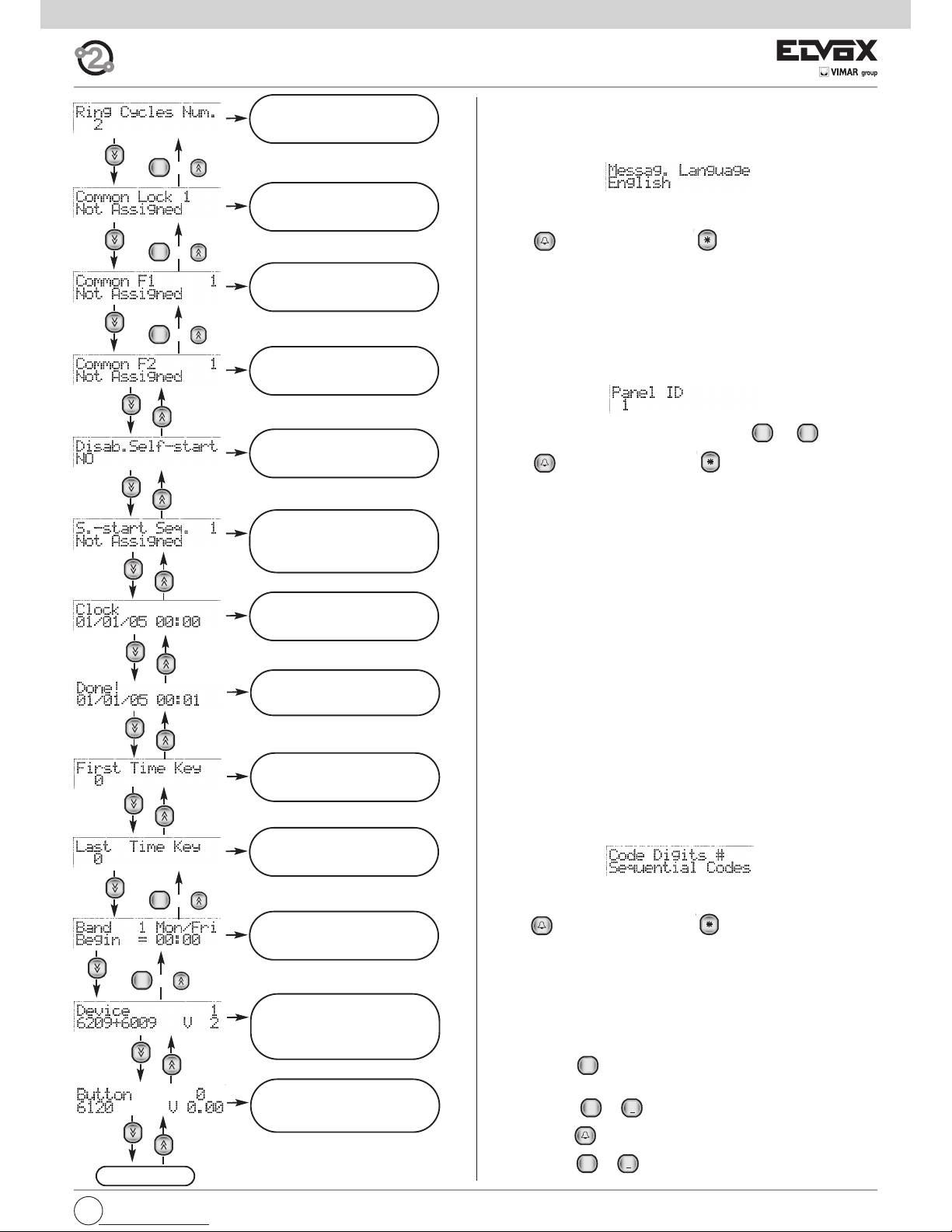
- Monitor/interphone ringtone cycles 2
- Common locks No association
- Common F1 No association
- Common F2 No association
- Self-start disable No
-
Self-start sequence (Master entrance panel only)
No association
- Clock 01/01/05 00:00
- Timed code enable No
- First timed code No association
- Last timed code No association
- Code validity time bands No association
- Audio/video door entry unit configuration
- Flag YES / NO
- Function key assignment
o Not Assigned
oIntercommunicating
o Self-Starting
o Auxiliary
o F1 function
o F2 function
o F1 function specific
o F2 function specific
o No Internal Call Ringtone
o No External Call Ringtone
- Call groups (4)
- Associated door call units (4)
- Volume or loudness for 6600 series appliances and derivatives
o Ringtone
o Speakerphone
o External ringtone type
o Brightness (only video door entry units)
o Contrast (only video door entry units)
o Door call ringtone type models Vimar®)
o Intercommunicating ringtone type (only for some models
Vimar®)
- Remote button module configuration.
The essential programming operations, which must be carried out before
any others, are:
- Slave entrance panel assignment. On systems with a single entrance
panel, the entrance panel will be defined as Master. In systems with several entrance panels, regardless of type (alphanumeric, push-buttons),
one will be defined as MASTER and the others as SLAVE.
- Entrance panel ID, entrance panel identification code. In systems with
several entrance panels, the SLAVE entrance panels (alphanumeric,
push-buttons, landing) will be identified with a different code for each.
PARAMETER PROGRAMMING
(Make the modifications by connecting one entrance panel at a time)
In systems with several entrance panels, it is necessary to distinguish one
MASTER entrance panel (one only) and the others as SLAVE entrance panels, regardless of type (alphanumeric, push-buttons, landing). All entrance
panels are supplied already set up as MASTER entrance panels.
Alphanumeric entrance panels are set up as MASTER or SLAVE by the software programming of the identification code of the entrance panel. Until
the identification codes of all entrance panels have been assigned, it is advisable to programme the entrance panels by connecting them to the system one at a time.
Connect the entrance panel defined as MASTER last.
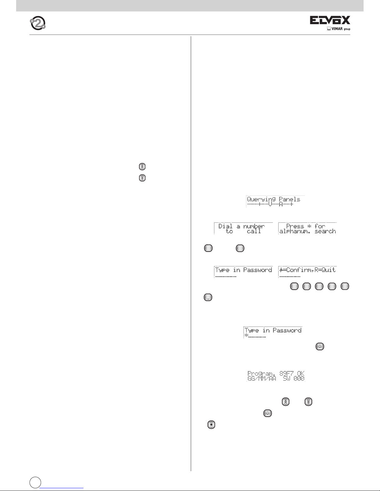
Procedure for accessing parameter programming mode
- Power up the entrance panel or, if applicable, press the “RESET-2” pushbutton (next to the loudspeaker).
- When switched on or reset, the entrance panel (only if defined as MASTER) queries the system as it searches for other entrance panels, and
displays the message:
- Wait for the entrance panel to return to the rest state and display the
messages:
- Press the and push-buttons simultaneously (if applicable, first press
and then ).
- Release the push-buttons.
- When the following messages are displayed alternately
key in the password, which is by default
- Each time you press a button a short “beep” is emitted, an asterisk “*”
appears on the display and you have a further 25 seconds (timeout) to
press the next push-button. If this time limit is exceeded, the entrance
panel exits programming mode
.
- After keying in the password press the push-button . If the password is incorrect, the entrance panel returns to the rest state and exits
the procedure, otherwise, it goes into parameter programming mode
and displays the following message:
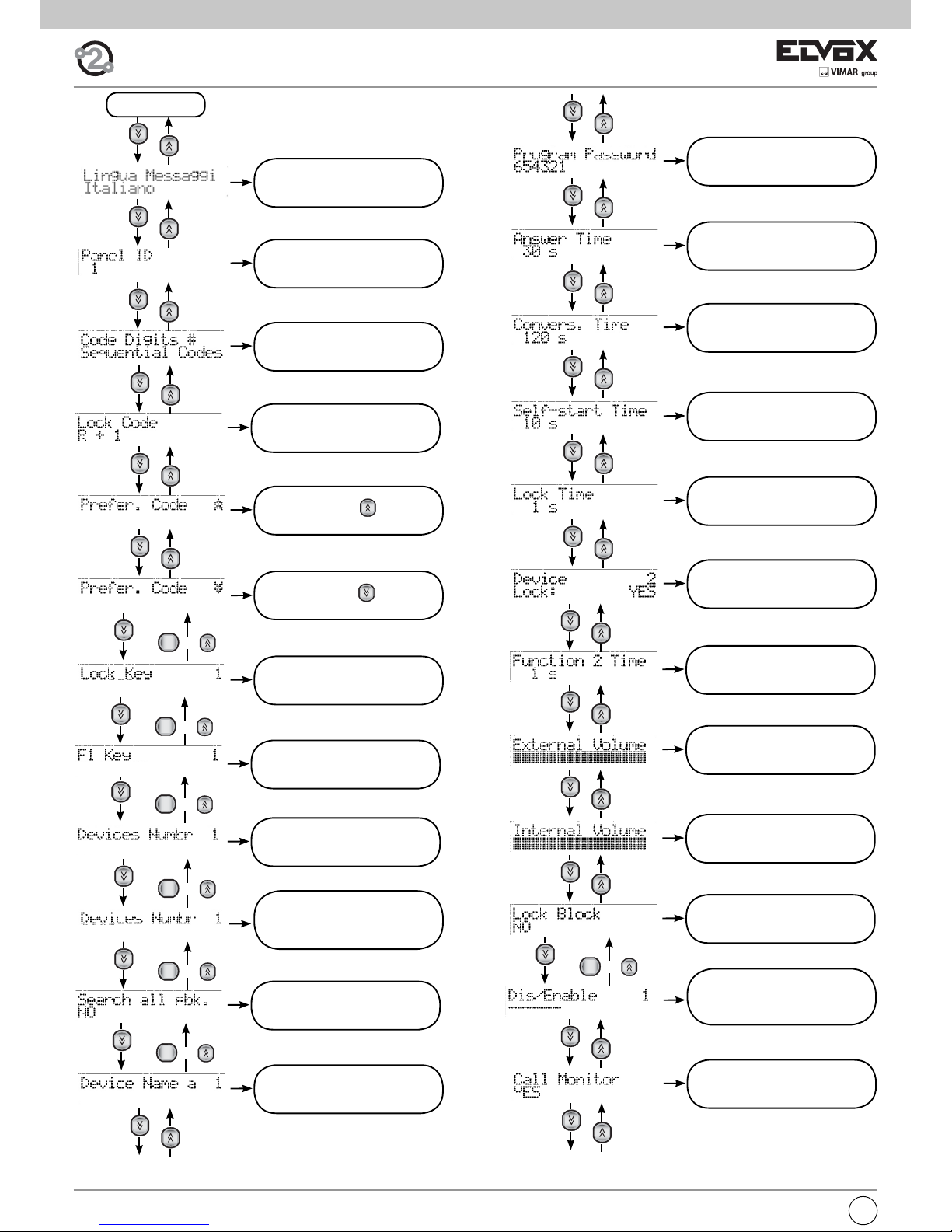
Parameter programming procedure
Once in programming mode, use the and push-buttons to
move between parameters, the push-button to confirm changes, and
the push-button to cancel changes. The 1st line of the display normally shows the current parameter and the 2nd line shows the value assigned to it. During programming, no more than about 30 seconds (timeout)
must elapse between one press of a push-button and the next. If this time
limit is exceeded, the entrance panel exits programming mode.
4
GHI
R
1
2
ABC3DEF
4
GHI5JKL
6
MNO
Page 6
I
6
SEQUENCE
1.1
MESSAGE LANGUAGE
1.2
ENTRANCE PANEL ID
1.3
NUMBER OF CODING DIGITS
2.3
PROGRAMMING
PASSWORD
2.4
ANSWER TIME
2.5
CONVERSATION TIME
2.6
SELF-START TIME
2.9
FUNCTION 2 TIME
3.0
EXTERNAL VOLUME
3.1
INTERNAL VOLUME
3.2
LOCK BLOCK
1.4
LOCK CODE
R
o x 200
R
o x 200
R
o x 200
2.8
FUNCTION 1 TIME
1.8
KEY F1
R
o x 200
1.9
KEY F2
R
o x 200
3.3
ENABLINGS/DISABLINGS
2.7
LOCK TIME
2.1
SEARCH THE ENTIRE AGENDA
R
o x 200
3.4
ENTRANCE PANEL RINGTONE
REPETITION
R
o x 200
2.2
DEVICE NAMES
1.5 PREFERENTIAL
CODE
1.6 PREFERENTIAL
CODE
1.7
LOCK PASSWORDS
2.0 DEVICE NUMBERING
(only if NUMBER OF CODING
DIGITS differs from
SEQUENTIAL CODE)
Page 7
7
I
4.0 SELF-START
SEQUENCE
(FOR MASTER ENTRANCE
PANEL ONLY)
4.7
CHANGING INTERPHONES/
MONITORS INTERPHONES
CONFIGURATION
SEQUENCE
R
o x 200
4.4
FIRST TIMED CODE
4.5
LAST TIMED CODE
4.6
CODE VALIDITY TIME BANDS
4.3
TIMED CODE ENABLE
4.2
CLOCK
R
o x 4
- 1.1 MESSAGE LANGUAGE
Indicates the message display mode, in Italian or English.
Default value = English.
When the following message is displayed in the 1st line:
Press 1 for “ITALIAN” and 2 for “ENGLISH” (or other language depending
on the software version).
Press to confirm the change or to cancel. When you confirm
the change, the message “Fatto!” or “Done!” will appear, depending on
the language selected.
- 1.2 ENTRANCE PANEL ID
Identify the entrance panel with a code from 1 to 15. If the value is 1, the
entrance panel is set as MASTER; from 2 to 15, it is set as SLAVE.
Default value = 1.
When the following message is displayed in the 1st line:
Key in the identification code with push-buttons to .
Press to confirm the change or to cancel. When you confirm
the change, the entrance panel checks the availability of the code. If there
is already another entrance panel in the system connected with the same
code, the message “Panel ID .. already in use” appears, and it is necessary to enter a different code. If the code is greater than 15, the message
“Over limit” appears. If it is correct, the message “Done!” appears.
It is possible to use 0 for temporarily “unprogramming” the entrance
panel.
- 1.3 NUMBER OF ENCODING DIGITS
Sets the type of encoding for calls to interphones and monitors/interphones.
The modes are as follows:
- Sequential encoding: the interphones/monitors interphones are numbered with codes from 1 to 200 (physical encoding for entrance panels
with push-buttons). In this case, keying in 0 before the other digits is
optional, e.g. the codes 001, 01 and 1 are effectively the same.
- 4-digit encoding, the audio/video door entry units are numbered from
1 to 9999. In the following case the codes can have from 1 to 4 digits.
This parameter activates parameter 2.0 DEVICE NUMBERING.
- 8-digit encoding, the audio/video door entry units are numbered from
1 to 99999999. In the following case the codes can have from 1 to 8 digits. This parameter activates parameter 2.0 DEVICE NUMBERING.
Default value = sequential encoding.
Note: In case of numbering with 4 or 8 digits, the 0s on the left are significant. For example 14, 014, 0014 are three separate numbers.
When the following message is displayed in the 1st line:
Press push-buttons 1, 2 or 3 for sequential, 4-digit or 8-digit encoding respectively.
Press to confirm the change or to cancel. When you confirm
the change, the message “Done!” will appear.
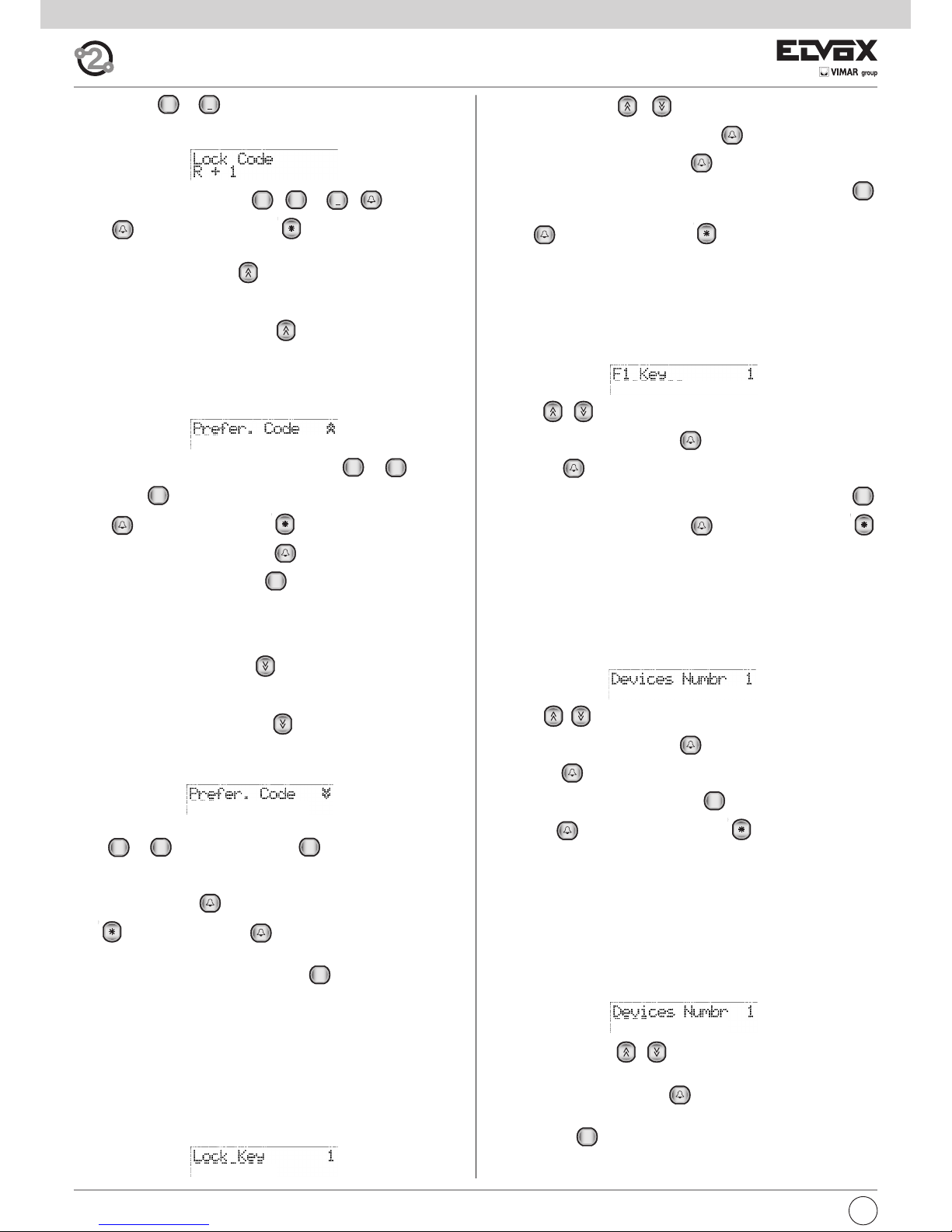
- 1.4 LOCK CODE
Sets the necessary push-buttons for activating the door lock release function directly from the entrance panel. On pressing the push-buttons it is
then necessary to key in one of the 200 8-digit codes recorded in parameter 1.7 LOCK PASSWORDS.
The modes are as follows:
- Push-button : this type of dialling can be inconvenient if the call
codes require 0 as the first digit.
- Push-buttons + ,, pressed simultaneously.
- Push-button , with entrance panel in rest state.
Default value = + .
1
R1R
0
+
9
WXYZ
0
+
3.5
NUMBER OF RINGTONE CY-
CLES
3.6
COMMON LOCKS
3.7
COMMON F1
3.8
COMMON F2
R
o x 4
R
o x 4
R
o x 4
3.9
SELF-START DISABLE
4.8
REMOTE BUTTON MODULE
CONFIGURATION
Page 8
I
8
Default value = + .
When the following message is displayed in the 1st line:
Press push-buttons 1, 2 or 3 for , + , respectively.
Press to confirm the change or to cancel. When you confirm
the change, the message “Done!” will appear.
- 1.5 PREFERENTIAL CODE
Assigns to the push-button a call code to an interphone or monitor interphone. Without pressing other push-buttons, it is possible to call a given
device by pressing the push-button .
The type of call code depends on the value set in parameter 1.3 NUMBER OF ENCODING DIGITS(3, 4 or 8 digits).
Default setting = (empty).
When the following message is displayed in the 1st line:
Key in all digits of the call code with push-buttons al . Use the
push-button to cancel the last digit entered.
Press to confirm the change or to cancel. To change the value
previously set, press the push-button before the numeric digits, and
use the digits and the push-button to change the value. When you
confirm the change, the message “Done!” will appear. If parameter 1.3
NUMBER OF ENCODING DIGITS is set as sequential, the entrance panel
checks that the value entered does not exceed 204; if it does, the message
“Over limit” appears.
- 1.6 PREFERENTIAL CODE
Assigns to the push-button a call code to an interphone or monitor interphone. Without pressing other push-buttons, it is possible to call a given
device by pressing the push-button .
The type of call code depends on the value set in parameter 1.3 NUMBER OF ENCODING DIGITS(3, 4 or 8 digits).
Default setting = 000, 0000 or 00000000 (parameter disabled).
Enter the call code complete with all the digits by using the push-buttons
from to . Use the push-button to cancel the latest digit
entered.
Press the push-button to confirm the modification or the push-but-
ton to cancel. If you press before the push-button before the
numerical digits, the already recorded number gets changed; to modify
the value use the digits and the push-button . On confirmation of the
modification, the message “Done” is displayed. If the parameter 1,3 “Number of coding digits” gets entered as sequential, the panel verifies that the
entered value does not exceed 204; if it does exceed this value, this is indicated by the message: “Over limit”.
The numbers from 201 to 204 correspond to porter switchboards.
- 1.7 LOCK PASSWORD
It is possible to record up to 200 different codes made up of 8 digits, to
open the lock directly from the keypad of the entrance panel (see parameter 1.4 LOCK CODE). Default setting = (empty).
When the following message is displayed in the 1st line:
R
R
9
WXYZ
0
+
R
R
9
WXYZ
0
+
1
R
0
+
1
R
Use the push-buttons to select one of the 200 passwords. If
applicable, key in the password and press to select it.
Next to the desired password, press to access change mode.
Key in the code you want to record (max. 8 digits); if necessary, press
to delete the last digit entered.
Press to confirm the change or to cancel. When you confirm
the change, the message “Done!” will appear.
- 1.8 F1 CODES
It is possible to record up to 200 different max. 8-digit codes for controlling F1 directly from the entrance panel keypad.
Default setting = (empty).
When the following message is displayed in the 1st line:
Use the push-buttons to select one of the 200 codes. If appli-
cable, key in the code and press to select it. Next to the desired
code, press to access change mode.
Key in the code you want to record (max. 8 digits); if necessary, press
to delete the last digit entered. Press to confirm the change or
to cancel. When you confirm the change, the message “Done!” will appear!”.
- 1.9 F2 CODES
It is possible to record up to 200 different max. 8-digit codes to control F2
directly from the entrance panel keypad.
Default setting = (empty).
When the following message is displayed in the 1st line:
Use the push-buttons to select one of the 200 codes. If appli-
cable, key in the code and press to select it. Next to the desired
code, press to access change mode. Key in the code you want to re-
cord (max. 8 digits); if necessary, press to delete the last digit ente-
red. Press to confirm the change or to cancel. When you
confirm the change, the message “Done!” will appear!”.
- 2.0 DEVICE NUMBERING
If parameter 1.3 NUMBER OF ENCODING DIGITS is set to 4 or 8 digits, it
is necessary to assign a 4- or 8-digit call code to each interphone and
video interphone.
The mapping associates the physical code (from 1 to 200) of each interphone and video interphone with the call code.
Default setting = (empty).
When the following message is displayed in the 1st line:
Use the push-buttons to select one of the 200 physical codes
(device ID). If applicable, key in the code and press to select it.
Next to the desired code, press to access change mode.
Key in the complete call code you want to record (up to 4 or 8 digits); if ne-
cessary, press to delete the last digit entered.
R
R
R
R
Page 9
9
I
Press on confirmation the change or to cancel. When you confirm the change, the message “Done!” will appear. If the call code has been
assigned, the entrance panel displays the message “Code ... used by ...”.
To cancel a code, select the physical code in question, press to ac-
cess change mode, enter one and press .
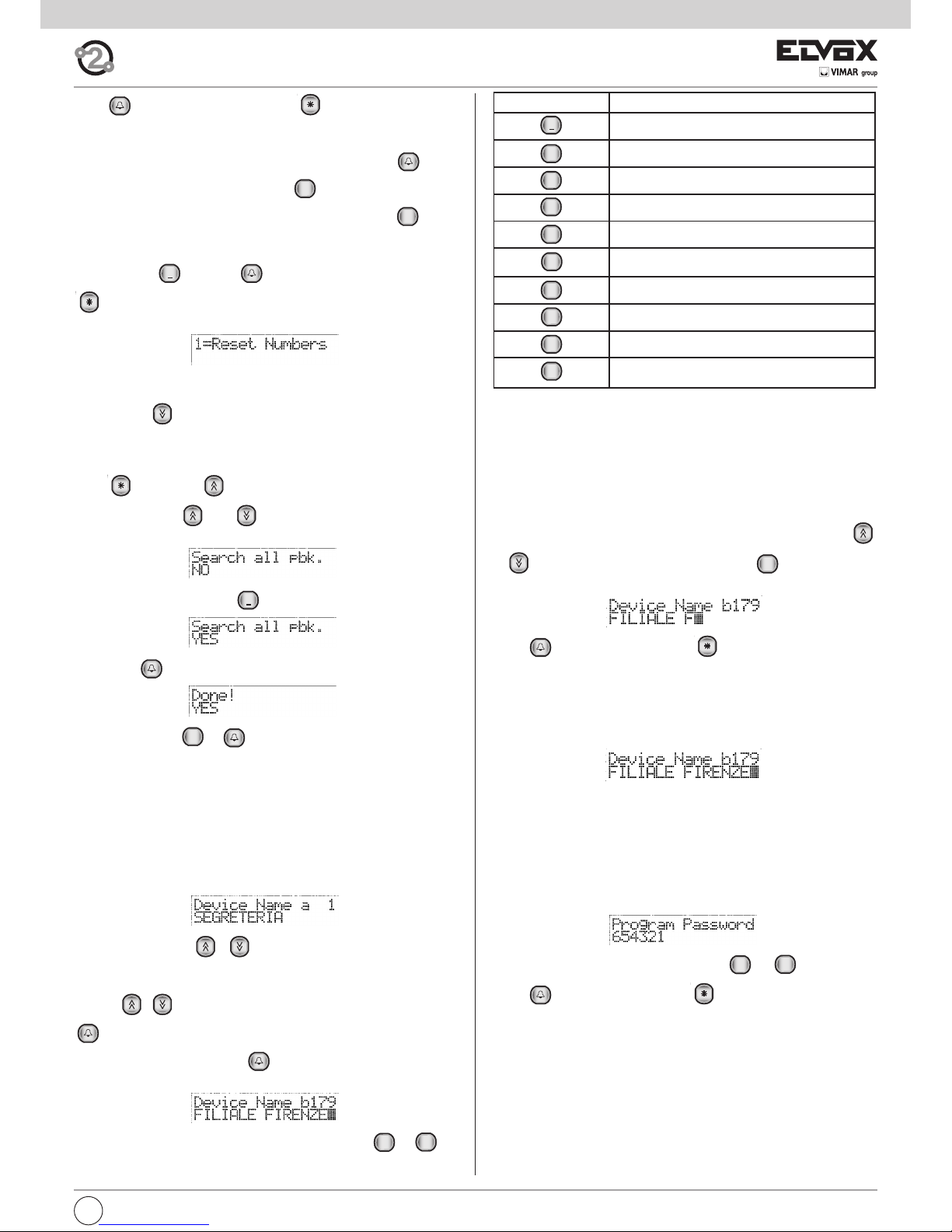
To cancel all the associations, next to any physical code press . When
the message:
appears, press and then to confirm the cancellation, or press
to escape. After confirming the operation, wait for completion of the
cancellation process.
- 2.1SEARCH THE ENTIRE AGENDA
Press the key to move to the next item, which enables configuration
of the panel to scroll through the entire agenda (see paragraph 6.2) by entering an empty name as the search criteria. Normally at least the first letter of the name to be searched should be entered. With the flag selected,
press followed by to see the first name in the list, regardless of
the initial. Use keys and to scroll through the entire agenda.
This function is disabled by default:
To activate the function, press :
followed by :
To deactivate, press e .
- 2.2 DEVICE NAMES
ELVOX TWO WIRE alphanumeric entrance panels are equipped with an
electronic name index for 200 users. Each user can be assigned a pair of
names (a and b) of 16 characters each.
Default value = no association
Note: The porter switchboards, corresponding to numbers 201 - 204,
have a fixed name Switchboard 1.... Switchboard 4.
When the following message is displayed in the 1st line:
Use the push-buttons to select one of the 200 users.
Two lines, a and b, correspond to each user. To select these, use the push-
buttons . If applicable, key in the number of the user and press
to select it.
Next to the desired line, press to access change mode. Once in
change mode, a flashing cursor shows where to enter the character.
To enter characters/symbols, use the push-buttons from to .
0
+
1
9
WXYZ
0
+
1
0+0
+
BUTTON SYMBOL
1
<spazio>1@.,:;?!()<>
2
ABC
ABC2abcБАГЕДЖЗИбагеджзи
3
DEF
DEF3defпЙИКМйикм
4
GHI
GHI4ghiÍÌíì
5
JKL
JKL5jkl
6
MNO
MNO6mnoСсУТХЦутхц
7
PQRS
PQRS7pqrsRŠršß
8
TUV
TUV8tuvЪЩЬЩъщьщ
9
WXYZ
WXYZ9wxyzÝZýz
0
+
0_$&*#+-=/%"'
Each push-button has more than one character/symbol assigned to it (see
previous table). To reach the desired symbol, press several times before
the timeout of 2 seconds, which is renewed each time you press a key.
If the symbol entered previously was a capital letter, even if you change
push-button, you will re-start with a capital. If it was lower case, you will restart in lower case. If it was a digit, you will re-start with a digit.
To enter a character/symbol located on a different push-button from the
one previously pressed, it is not necessary to wait for the end of the timeout.
While entering symbols, it is possible to use the push-buttons
to move along the line, and the push-button to delete the character preceding the cursor.
Press to confirm the change or to cancel.
After confirmation, the entrance panel will check if the name entered is al-
ready in use by another user. If so, the message “..... used by ...” will ap-
pear, and it will be necessary to enter another name. Alternatively, the
message “Done!” will appear. If at least one name has been changed, on
completion, the names will be ordered alphabetically. This process takes
about 10 seconds for a full name index.
Example :
To key in the previous name, press the following push-buttons in succession: 333 444 555 444 2 555 33 1 333 444 777 33 66 9999 33
- 2.3 PROGRAMMING PASSWORD
Sets the password for access to the phases of keypad programming.
Default value = 654321
When the following message is displayed in the 1st line:
Key in the new password with push-buttons to .
Press to confirm the change or to cancel.
When you confirm the change, the message “Done!” will appear.
The password is not needed when programming with the programming
module Type 950C and software SaveProg.
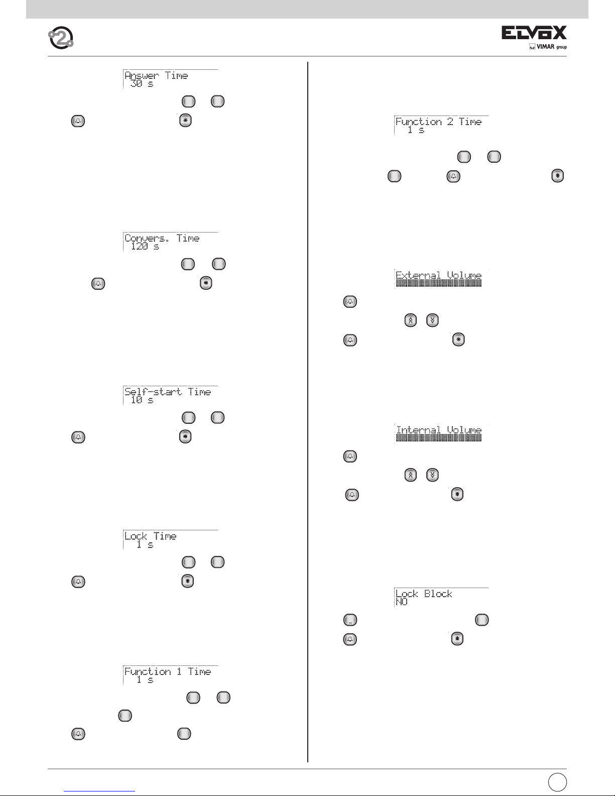
- 2.4 ANSWER TIME
To be programmed as required. This is the time interval, expressed in seconds, that the entrance panel waits after a call has been terminated and
the time that the handset of the interphone/monitor is raised. If the handset
is not raised within this time interval, the entrance panel disables the interphone/monitor. If the handset is raised before this interval elapses, the entrance panel starts to count the conversation time.
Default value = 30 s, minimum value 1 s, maximum value 255 s.
9
WXYZ
0
+
R
Page 10
I
10
When the following message is displayed in the 1st line:
Key in the new time with push-buttons to .
Press to confirm the change or to cancel. If the value is over
255, the message “Over limit” appears, whereas if the value is correct, the
message “Done!” appears.
- 2.5 CONVERSATION TIME
To be programmed at the user's discretion. This is the time interval, expressed in seconds, that the entrance panel counts, from the time at which
the handset is raised after the call. The entrance panel disables the extension after this time interval.Default value = 120 s, minimum value 10 s, maximum value 2550 s.
When the following message is displayed in the 1st line:
Key in the new time with push-buttons to (in increments of 10
sec.). Press to confirm the change or to cancel. If the value is
over 2550, the message “Out of range” appears, whereas if the value is
correct, the message “Done!” appears.
- 2.6 SELF-START TIME
To be programmed at the user's discretion. This is the time interval, expressed in seconds, that the entrance panel remains engaged with a monitor/interphone, from activation by means of the self-start function. The
entrance panel disables the extension after this time interval.
Default value = 10 s, minimum value 1 s, maximum value 255 s.
When the following message is displayed in the 1st line:
Key in the new time with push-buttons to .
Press to confirm the change or to cancel. If the value is over
255, the message “Out of range” appears, whereas if the value is correct,
the message “Done!” appears.
- 2.7 LOCK TIME
To be programmed at the user's discretion. This is the activation time of the
lock connected between terminals S+ / S- and +12V / SR.
Default value = 1 s, minimum value 0 s., maximum value 255 s.
When the following message is displayed in the 1st line:
Key in the new time with push-buttons to .
Press to confirm the change or to cancel. If the value is over
255, the message “Out of range” appears, whereas if the value is correct,
the message “Done!” appears.
- 2.8 FUNCTION 1 TIME
To be programmed at the user's discretion. This is the activation time of the
device connected between terminals +12V / F1.
Default value = 1 s, minimum value 0.5 s, maximum value 255 s.
When the following message is displayed in the 1st line:
Key in the new time with push-buttons to . For the minimum
value of 0.5 s. enter only.
Press to confirm the change or to cancel. If the value is over
255, the message “Out of range” appears, whereas if the value is correct,
the message “Done!” appears.
0+0
+
9
WXYZ
0
+
9
WXYZ
0
+
9
WXYZ
0
+
9
WXYZ
0
+
9
WXYZ
0
+
- 2.9 FUNCTION 2 TIME
To be programmed at the user's discretion. This is the activation time of the
device connected between terminals +12V / F2. Default value = 1 s, minimum value 0.5 s, maximum value 255 s.
When the following message is displayed in the 1st line:
Key in the new time with push-buttons to . For the minimum
value of 0.5 s. enter only. Press to confirm the change or
to cancel. If the value is over 255, the message “Out of range” appears,
whereas if the value is correct, the message “Done!” appears.
- 3.0 EXTERNAL VOLUME
To be programmed at the user's discretion. This is the volume of the loudspeaker of the entrance panel, settable on 16 levels.
Default value = 15, minimum value 0, maximum value 15.
When the following message is displayed in the 1st line:
Press to access change volume mode.
Press the push-buttons to increase or reduce the volume.
Press to confirm the change or to cancel. When you confirm
the change, the message “Done!” will appear.
- 3.1 INTERNAL VOLUME
To be programmed at the user's discretion. This is the volume of the entrance panel microphone, settable on 4 levels.
Default value = 3, minimum value 0, maximum value 3.
When the following message is displayed in the 1st line:
Press to access change volume mode.
Press the push-buttons to increase or reduce the volume.
Press to confirm the change or to cancel. When you confirm
the change, the message “Done!” will appear.
- 3.2 LOCK BLOCK
To be programmed as required. Activation of the lock block enables control of the lock only when the panel is in call, conversation or self-start status.
Default value = block disabled
When the following message is displayed in the 1st line:
Press to enable the lock block or press to disable it.
Press to confirm the change or to cancel. When you confirm
the change, the message “Done!” will appear.
0
+
1
0
+
9
WXYZ
0
+
Page 11
11
I
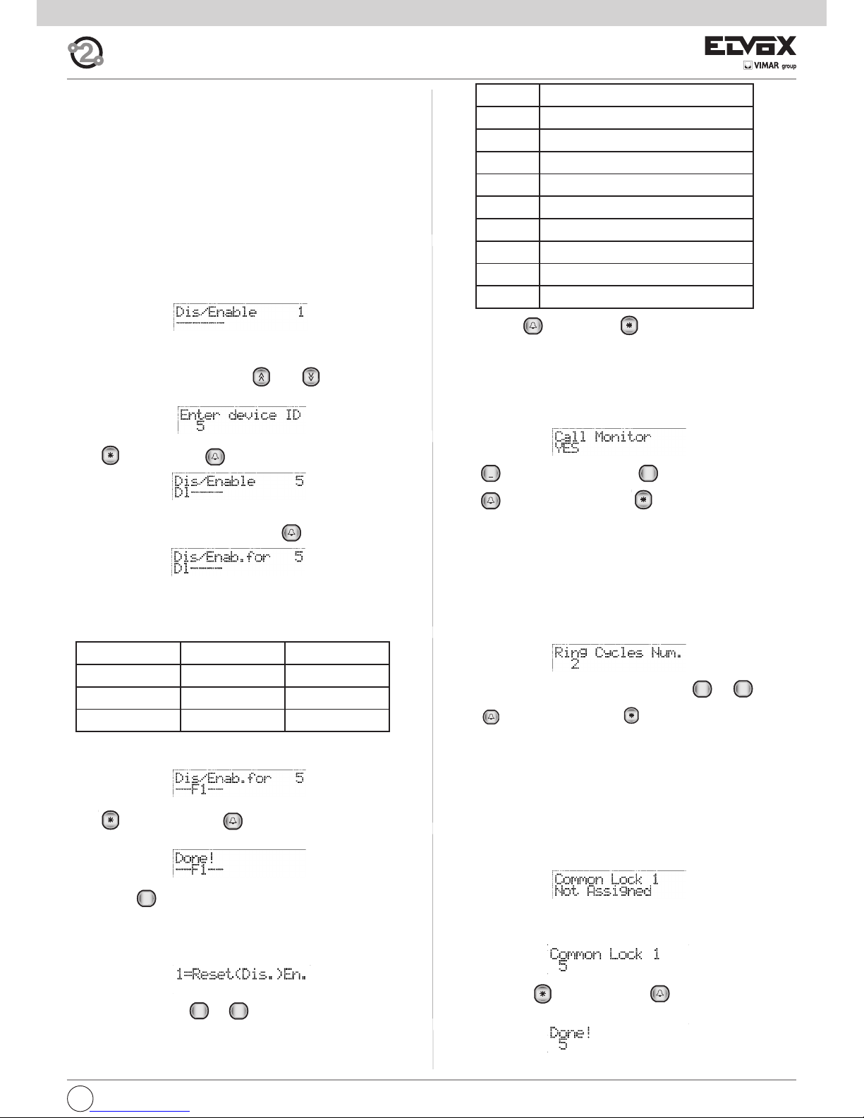
3.3 ENABLING/DISABLING
To be programmed as required. This function enables the user to programme, for each device, controls on certain commands received by the
entrance panel. This currently relates to the programming of common locks
F1 and F2.
It is possible to programme one or more entrance panels not to react in response to one or more interphones/monitor interphones when the lock or
F1 or F2 functions are activated.
It is also possible to programme the entrance panel in such a way that it
can only be activated by certain interphones/monitor interphones.
In order to minimise the number of programming operations, if the entrance
panel already has at least one programmed common lock, the headings
act as enable signals.
The same applies to function F1 or F2. Since common locks are normally
used in building-complex type layouts, by programming one common lock
and enabling only the users of the respective staircase, fewer programming operations are necessary.
The default setting is no programming. The absence of programming is indicated by the symbol: “__”. To change the identification code of the inter-
phones/monitor interphones, use the and keys. Alternatively,
key in the numbers of the monitor or interphone from 1 to 200:
Press to cancel. Press to confirm.
To change the programming of the selected interphones/monitor interpho-
nes, when the current value is shown, press .
The correlation between programming, abbreviations and keys is as follows:
PROGRAMMING ABBREVIATION KEY
Lock
Dl 1
F1 F1 2
F2 F2 3
- 3.4 ENTRANCE PANEL RINGTONE REPETITION
To be programmed as required. Enables repetition of the ringtone in the microphone of the entrance panel from which the call is being made.
Default value = enabled
When the following message is displayed in the 1st line:
Press to enable the ringtone and to disable it.
Press to confirm the change or to cancel. When you confirm
the change, the message “Done!” will appear.
- 3.5 NUMBER OF RINGTONE CYCLES
To be programmed at the user's discretion. This is the number of times
that the call is repeated in the monitor/interphone when a call push-button
is pressed. A ringtone cycle lasts for a total of 3 seconds (1 second of ringtone and 2 seconds of pause).
Default value = 2 times, minimum value 1, maximum value 20.
When the following message is displayed in the 1st line:
Key in the number of cycles with the push-buttons to .
Press to confirm the change or to cancel. If the value is over 20,
the message “Out of range” appears, whereas if the value is correct, the
message “Done!” appears.
- 3.6 COMMON LOCKS
To be programmed as required. This parameter enables indirect opening
of the lock, at the same time as the opening of the lock of another entrance
panel, at the command of an interphone/monitor interphone. Indirect opening can be associated with 4 different entrance panels.
Default value = no association, minimum value 1, maximum value 15.
When the following message is displayed in the 1st line:
Enter a number between 1 and 15, i.e. the ID of an entrance panel (in this
case the first of four possible choices) for controlling whose lock also the
current speech unit must activate its own:
To cancel, press . To confirm, press . Acceptance of the command, as in all cases, is shown on the first line of the display:
9
WXYZ
0
+0+
1
Button Action
0
Do nothing
1
Deselect
Se, F1, F2
2
Deselect
Se
3
Deselect
F1
4
Deselect
F2
5
Select
Se, F1, F2
6
Select
Se
7
Select
F1
8 Select F2
Confirm with or cancel with .
Pressing one of the keys alternately adds / removes the corresponding function. To set F1 only press 2 and 1 (or vice versa):
Press to cancel and press to confirm. Acceptance of the command, as for all the others, is shown in the first line of the display:
By using the key, you can skip all the intermediate steps and go
straight to the previous heading in the programming menu.
To change the settings of all the audio/video door entry units, the procedure is as follows.
For the ID key in no. 0. The display will show:
By pressing the buttons ... it is possible to choose what to
do, that is whether to engage or release the lock and whether with only
the lock, F1, F2 or all three.
The following table shows the actions.
8
TUV
0
+
R
Page 12
I
12
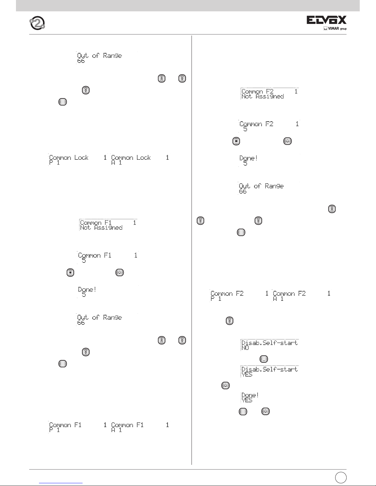
If the ID is outside the limit, the first line of the display will signal the incongruity:
To cancel the assignment, enter 0 for the ID.
It is possible to move from one index to another also by using and
.From position 1, press to move to the next item of the programming
menu. Press to move quickly, skipping all the intermediate steps, to the
previous item of the programming menu.
Whereas if you enter numbers from 21 to 36, then the end of the line is not
taken to be an entrance panel but an actuator.
Number 21 corresponds to the 1st relay of the 1st actuator, number 36 to
the second relay of the 8th actuator. On the contrary to the lock, F1 or F2,
the actuators are not subjected to locks as described in paragraph 3.3.
In the display phase the entrance panels are preceded by a letter “P”, the
actuators by an “A”.
- 3.7 COMMON F1
To be programmed as required. This parameter enables indirect activation of
the F1 function, at the same time as activation of the F1 function of another
entrance panel, at the command of an interphone/monitor interphone. Indirect
activation can be associated with 4 different entrance panels.
Default value = no association, minimum value 1, maximum value 15.
When the following message is displayed in the 1st line:
Enter a number between 1 and 15, i.e. the ID of an entrance panel (in this case
the first of four possible choices) for controlling whose F1 also the current
speech unit must activate its own:
To cancel, press . To confirm, press . Acceptance of the command,
as in all cases, is shown on the first line of the display:
If the ID is outside the limit, the first line of the display will signal the incongruity:
To cancel the assignment, enter 0 for the ID.
It is possible to move from one index to another also by using and
.From position 1, press to move to the next item of the programming
menu. Press to move quickly, skipping all the intermediate steps, to the
previous item of the programming menu.
Whereas if you enter numbers from 21 to 36, then the end of the line is not
taken to be an entrance panel but an actuator.
Number 21 corresponds to the 1st relay of the 1st actuator, number 36 to
the second relay of the 8th actuator. On the contrary to the lock, F1 or F2,
the actuators are not subjected to locks as described in paragraph 3.3.
In the display phase the entrance panels are preceded by a letter “P”, the
actuators by an “A”.
R
R
- 3.8 COMMON F2
To be programmed as required. This parameter enables indirect activation
of the F2 function, at the same time as activation of the F2 function of another entrance panel, at the command of an interphone/monitor interphone.
Indirect activation can be associated with 4 different entrance panels.
Default value = no association, minimum value 1, maximum value 15.
When the following message is displayed in the 1st line:
Enter a number between 1 and 15, i.e. the ID of an entrance panel (in this
case the first of four possible choices) for controlling whose F2 also the
current speech unit must activate its own:
To cancel, press . To confirm, press . Acceptance of the command, as in all cases, is shown on the first line of the display:
If the ID is outside the limit, the first line of the display will signal the incongruity:
To cancel the assignment, enter 0 for the ID.
It is possible to move from one index to another also by using and
.From position 1, press to move to the next item of the program-
ming menu. Press to move quickly, skipping all the intermediate
steps, to the previous item of the programming menu.
Whereas if you enter numbers from 21 to 36, then the end of the line is not
taken to be an entrance panel but an actuator.
Number 21 corresponds to the 1st relay of the 1st actuator, number 36 to
the second relay of the 8th actuator. On the contrary to the lock, F1 or F2,
the actuators are not subjected to locks as described in paragraph 3.3. In
the display phase the entrance panels are preceded by a letter “P”, the actuators by an “A”.
- 3.9 SELF-START DISABLE
Press the key to move to the next item, which enables configuration
of the main panel to disable the self-start function on a system level. The
function is enabled by default, and therefore select NO to disable:
To activate the function, press :
followed by :
To deactivate, press and .
- 4.0 SELF-START SEQUENCE
To be programmed at the user's discretion but only on the MASTER entrance panel (with ID=1). This parameter allows you to assign to the selfstart push-button of each video interphone (and interphone), the cyclical
start-up of a sequence of entrance panels. Each sequence must consist of
a maximum of 15 entrance panels and contain duplicates of the same entrance panel.
Default value = no association.
0
+
1
R
Page 13

13
I
- 4.2. CLOCK
The clock can be programmed so that the service is performed correctly.
The date and time are stored also when the panel is switched off, for at
least 2 days, by means of a SuperCap capacitor. There are no batteries of
any type. On initial activation of the clock, or when the panel is left switched off for a prolonged period, the date is set to the 1st January 2005 and
the time at 00:00.
It can be modified via the keypad. Press the key . The modifiable field
is indicated by a rectangle to the right:
To move to the right, use key , and to the left use . Modify the
values by means of the keys to .
On completion confirm by means of . If the values are correct the display then shows:
If there is an error, for example if the month is set as 88, modifications are
rejected and the rectangle moves to the position of the error:
The weekday does not need to be entered as it is calculated automatically based on the date, by means of the Zeller algorithm.
- 4.3. TIMED CODE ENABLE
The service must be configured and then enabled by means of this parameter.
If necessary, though completely configured, this function can be disabled,
to obtain temporary suspension of the service, while all settings remain
enabled for operation. The service is disabled by default.
Press :
followed by to enable the function:
and disable the function.
- 4.4. FIRST TIMED CODE
This parameter specifies the first code to be used for the Timed Code function. No code is set by default:
To modify, enter a number from 1 to 200 to by means of the
keys :
To clear settings, enter 0. Confirm by means of :
If the code number is outside the range 0..200, the error message is
shown:
9
WXYZ
0+0
+
1
9
WXYZ
0
+
When the following message is displayed in the 1st line:
Use the push-buttons to select one of the 204 physical codes
(device ID) corresponding to an audio/video door entry unit and lastly the
switchboards.
Note: The switchboards 945F at this time do not perform the function of
self-starting.
If applicable, key in the code and press to select it.
Next to the desired code, press to access change mode.
Enter the entrance panel ID code or codes (maximum 15 characters).
To enter the codes, press push-buttons to for entrance panels
1 to 9. For entrance panels 10 to 15, first press and then one of the
push-buttons from to .
When you press , a “?” appears on the display; when you press the
next number, a letter is entered (A->10, B->11, C->12, D->13, E->14, F>15).
Use the push-button to cancel the last digit entered.
Press to confirm the change or to cancel. When you confirm
the change, the message “Done!” will appear.
During this phase, it is possible to use the “notepad block” function to
help with the duplication of the codes. While in change mode and without
the ? displayed, press to record the sequence entered.
Exit change mode by pressing or .
Select another device, press to access change mode and then press
to replace the current sequence with the sequence recorded in the
notes. Press to confirm the change or to cancel.
To cancel all the associations, next to any physical code press . When
the message:
appears, press and then to confirm the cancellation, or press
to escape. After confirming the operation, wait for completion of the
cancellation process.
- 4.1 TIMED CODES
For 89F4/7 panels with the clock module, a function can be assigned to
enable a specific number of Lock Codes (paragraph 1.7), F1 codes (paragraph 1.8), F2 codes (paragraph 1.9) at specific times of the day only.
Two time bands are envisaged for the 24-hour period, each with a resolution of 30 minutes. This means that the user can specify the time start
and end interval in increments of 30 minutes:
00:00, 00:30, 01:00, 01:30, … 22:30, 23:00, 23:30
For further flexibility, the two time bands can be programmed separately
for weekdays (Monday to Friday) and weekends, or times in which most
situations are not considered fully "work" times (Saturday and Sunday).
For all three types of function (lock, F1 and F2) the set of codes has common start and and end numbers, but obviously the contents of the three
tables can be programmed differently.
The codes other than the selected set are always active. Only the selected codes are subject to timed limits. The service can be temporarily disabled by means of a programmed parameter. In this case the specified
codes are never active, while the other remain active.
1
0
+
R
0
+
5
JKL
0
+
0
+
9
WXYZ
1
Page 14

I
14
If the first code is higher than the second, or if one is programmed and the
other is not, a warning is displayed, requesting the user to check the other
code:
The valid codes are those in which the number ranges from the first and last
as specified, excluding the limits.
- 4.5. LAST TIMED CODE
Similar to the previous code, but referring to the last valid code.
- 4.6. CODE VALIDITY TIME BANDS
As specified above, there are two time bands for days from Monday to Friday and two for Saturday and Sunday. By default there is no setting, and
all start and end values are set at 00:00.
As the end value must be greater than the first value, this programming is
not valid. For example, a start value = 16:00 and end value = 16:00 would
not be valid, or start = 16:00 and end = 10:30.
To modify the time, press :
The double arrow appears on the right to indicate the option to use keys
, and to modify the time in increments of 30 minutes. Alternati-
vely use keys to to set the time:
If necessary use key and to modify the minutes:
Confirm by means of ::
- 4.7 CHANGING MONITOR/INTERPHONE CONFIGURATION
For each audio and video door entry unit installed in the system, it is possible to configure operating functions grouped in four zones “Flag”, “Programmable buttons”, “Call groups”, “Door call”. The audio/video door entry
units in the 6600 series have a fifth zone composed of the audio/video levels. To execute this procedure, the devices to be programmed (interphones
and monitors) have to be connected to the system and have to be identified with a code.
The entrance panel searches for the first device (interphone and monitor),
identified with the physical code 1, and analyses the type of associated
device (6209, 6209+6009, 6309, 6601, etc.).
Use the push-buttons to select one of the 200 devices. If ap-
plicable, key in the code of the device and press to select it.
Next to the desired device, press to access change mode. The configuration options change according to the type of device as indicated in
the following diagrams.
9
WXYZ
0
+
Once in configuration mode, use the push-buttons , and
to move between parameters, the push-button to confirm changes,
and the push-button to cancel changes. The 1st line of the display
shows the current parameter and the 2nd shows the value assigned to it.
R
Page 15
15
I
CLASS MEANING 6209 (+ 6009) 6309
YES = the monitor switches on when a panel
call is made (except for 6209)
YES = the green led is managed as
door open indicator
YES = the lock pushbutton is used by the device
NO =
the pushbutton is used externally (only for 6309/P, 6309/CP)
YES =
the stair light pushbutton is used by the device
NO =
the pushbutton is used externally (only for 6309/P, 6309/CP)
YES =
the self-start pushbutton is used by the device
NO = the pushbutton is used externally
(only for 6309/P, 6309/CP)
YES = if the F1 / F2 pushbutton is programmed
directly on a specific panel, only panels 1 to 8
can be programmed
NO = only panels 9 to 15
YES = the device is working in porter
switchboard mode
YES =
the device sends the lock command automatically
when a external speech unit/panel calls, if P6 is closed
YES = group G3 functions only for
external calls
YES = group G4 functions only for
internal calls
YES = eliminates the click sound
when a valid key is pressed
YES = does not activate the call repeated output
for intercommunicating calls
YES = group G1 functions only for external calls
YES = group G2 functions only for internal calls
YES = the monitor / interphone does
not ring for intercommunicating calls
YES = the monitor / interphone does
not ring for calls from panels
YES = After the automatic door lock activation
because of the Serr. Aut. flag with P6 close the
interphone or the video interphone cancels the call.
[NO] The possible automatic door lock does not
make the call end (default).
Usually used for a group master.
YES = the call is accepted, and then the
secondary units ring, even if the group master
has ringtone off and therefore does not ring.
NO = if a group master turns off the ringtone
none rings and there is a warning on the
entrance panel.
YES = the device has no timeout for the
intercommunicating conversation. For it to work
properly, both parties talking to each other must
have it on YES.
NO = (Default) and the intercommunicating
conversation lasts at most 5 minutes.
YES = If it is programmed for a head group, this
latter, at the call reception from the push-button
module type 6120, will inform the other members
that it is ringing. If it is programmed for the group
members, they will answer at the call from a type
6120 to their head group ringing. In this way it is
possible to divide the calls between external,
internal and outdoor calls.
NO = No reaction.
FLAG PROGRAMMING
Page 16

16
I
First door call
Fourth door call
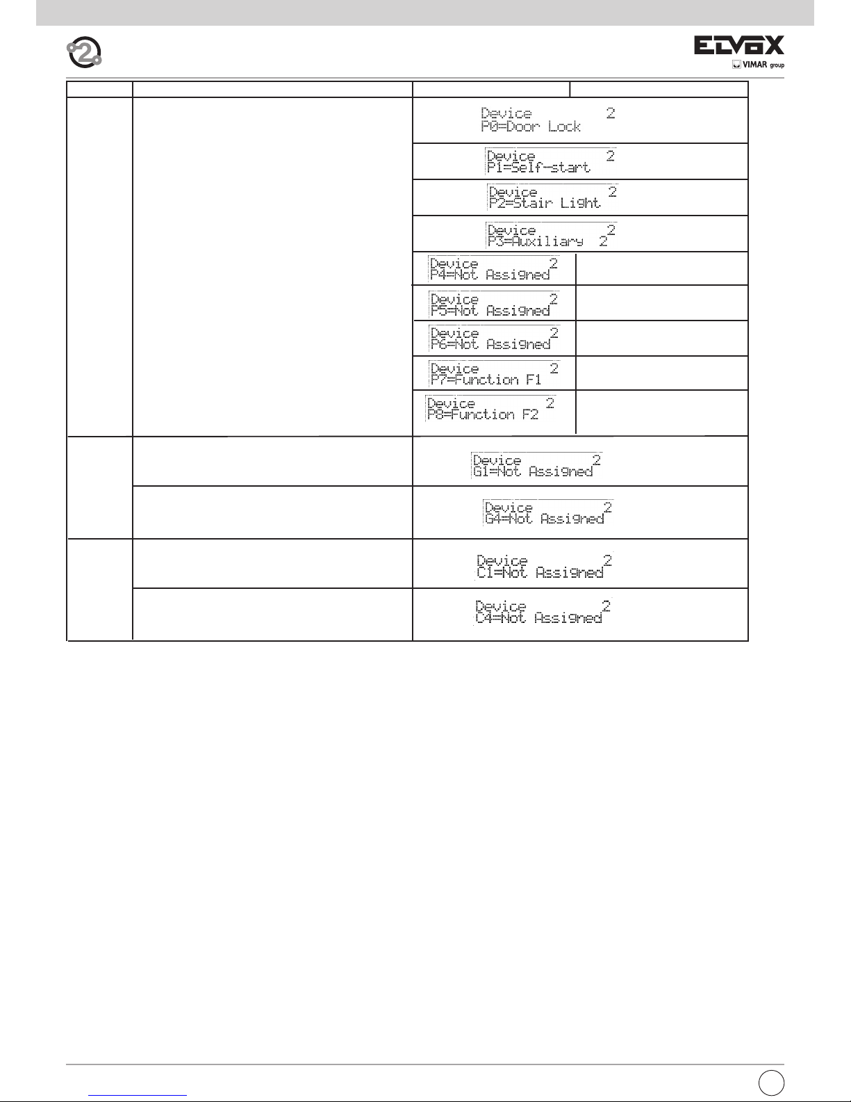
DOOR CALL
CLASS MEANING 6209 (+ 6009) 6309
P0 is lock push-button
Functions assigned to pushbuttons.
P1, P2, P3, P7 and P8 as default
(i.e. not programmed) take the
specified value
PROGRAMMABLE KEYS
First call group programming
Fourth and last call
group programming
GROUPS
Page 17

I
17
CLASS MEANING 6601 6611 8879
YES = the monitor switches on when
a panel call is made (not for 6601AU or 6611AU)
YES = the green led is managed
as door open indicator
YES = if the F1 / F2 pushbutton is programmed
directly on a specific panel, only panels 1 to 8 can
be programmed
NO = only panels 9 to 15
YES = the device is working in porter
switchboard mode
YES = group G3 functions only for
external calls
YES = group G4 functions only for
internal calls
YES = eliminates the click sound
when a valid key is pressed
YES = does not activate the call repeater output for
intercommunicating calls
YES = group G1 functions only for
external calls
YES = group G2 functions only for
internal calls
YES = the monitor / interphone dos
not ring for intercommunicating calls
YES = the monitor / interphone
dos not ring for calls from panels
[YES] pressing the door lock push-button ends
the conversation (default value in model /F of monitor)
NO = the door lock push-button operates normally
From version 4 of monitor and entrance panels.
[YES] to activate the audio connection press
the talk/listen push-button. To deactivate the audio
press the push-button again (default value on model
/F of monitor).
NO = To activate the audio connection the talk/listen
push-button must be kept pressed.
From version 4 of monitor and entrance panels.
FLAG PROGRAMMING
Valid only for some Vimar products.
[YES] the square button (self-start) becomes the second function regardless of the position of the mechanical switch.
NO = has the self-start function.
Valid only for some Vimar products.
[YES] there is home automation.
NO = (Default)
Usually used for a group master.
[YES] the call is accepted, and then the secondary
units ring, even if the group master has ringtone off
and therefore does not ring.
NO = if a group master turns off the ringtone none
rings and there is a warning on the entrance panel.
[YES] the device has no timeout for the intercommunicating conversation. For it to work properly, both
parties talking to each other must have it on YES.
NO = (Default) and the intercommunicating conversation lasts at most 5 minutes.
[YES] After the panel ring tones the monitor answers
automatically. Even the flag “T./L. On/Off:NO²”must
be set to YES.
NO = No automatic answer (default).
[YES] If it is programmed for a head group, this latter,
at the call reception from the push-button module
type 6120, will inform the other members that it is
ringing. If it is programmed for the group members,
they will answer at the call from a type 6120 to their
head group ringing. In this way it is possible to divide
the calls between external, internal and outdoor calls.
NO = No reaction.
Page 18
18
I
First door call
Fourth door call
DOOR CALL
CLASS MEANING 6209 (+ 6009) 6309
P0 is lock push-button
Functions assigned to pushbuttons.
P1, P2, P3, P7 and P8 as default
(i.e. not programmed) take the
specified value
PROGRAMMABLE KEYS
First call group programming
Fourth and last call
group programming
GROUPS
Page 19

I
19
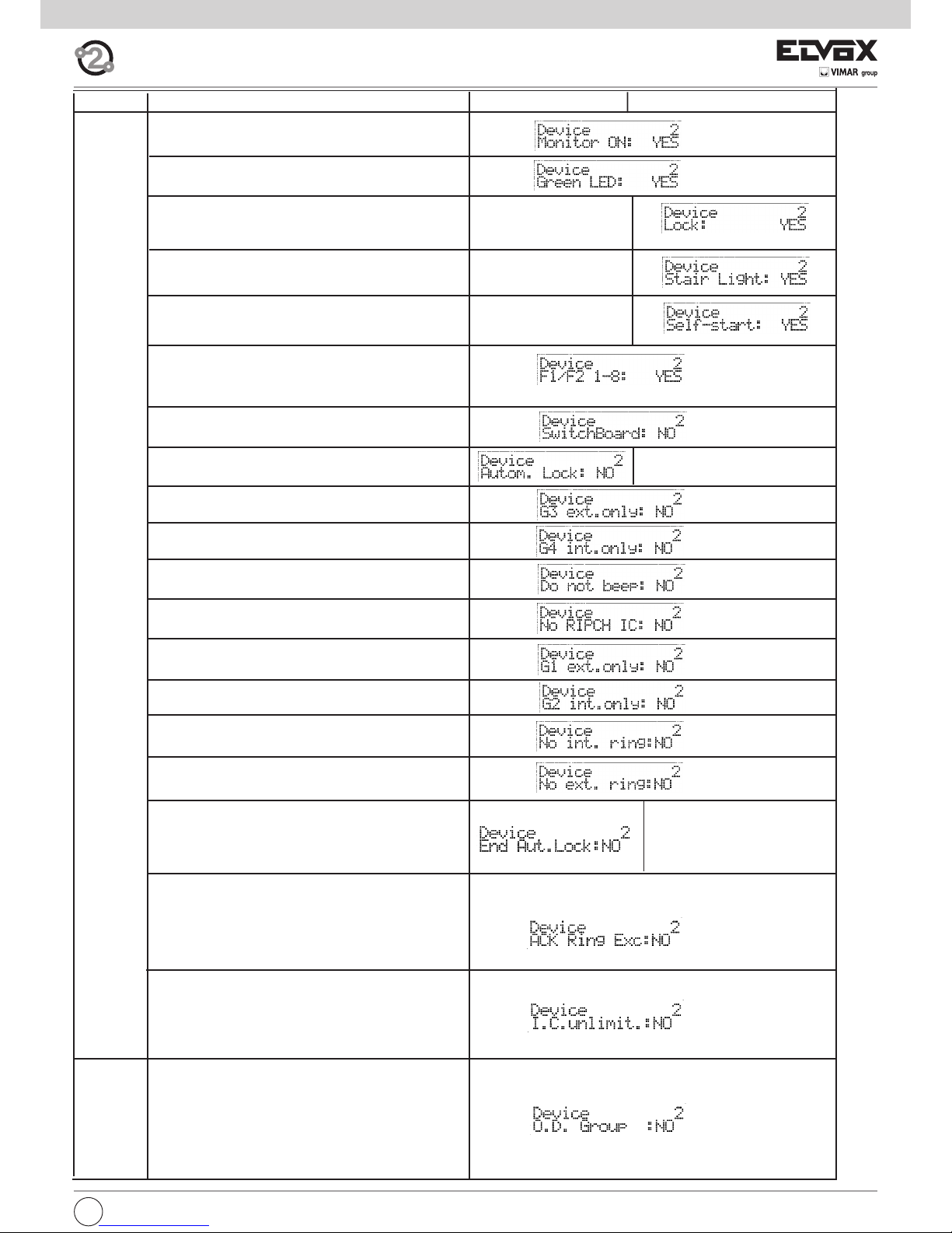
- FLAG PROGRAMMING
Next to the desired FLAG, press 1 for YES and 0 for NO.
Press to confirm the change. When you confirm the change, the
message “Done!” will appear.
FLAG description
Monitor Switch-on -> [YES] The monitor switches on when called by the
entrance panel (default).
[NO] The monitor does not switch on when called,
but can switch on with the self-start function or by
replying.
Green LED -> [YES] The green LED is used to indicate that the
door is open (default).
[NO] The LED remains OFF.
Lock -> [YES] The lock push-button is set to open the door
(default).
[NO] The lock push-button is used as an N.O.
push-button with free contacts, for types 6309/P
and 6309/CP only.
Stair light -> [YES] The stair light push-button is set to activate
the 1st auxiliary function of the 1st relay (default).
[NO] The stair light push-button is used as an N.O.
push-button with free contacts, for types 6309/P
and 6309/CP only.
Self-start -> [YES] The self-start push-button is set for self-start
of the monitor (default).
[NO] The self-start push-button is used as an N.O.
push-button with free contacts, for types 6309/P
and 6309/CP only.
F1/F2 1-8 -> [YES] If a push-button is programmed for direct
F1/F2 to a specific entrance panel, the push-button can manage F1/F2 of entrance panels 1 to 8
(default).
[NO] If a push-button is programmed for direct
F1/F2 to a specific entrance panel, the push-button can manage F1/F2 of entrance panels 9 to 15
(default).
Switchboard -> [YES] The device works in a system with switchbo-
ard.
[NO] The device does not work in a system with
switchboard (default).
Auto. Lock ->
[YES] The device sends the door lock release command on receipt of a call from the entrance panel if
push-button P6 is closed.
[NO] The device does nothing (default).
G3 ext. only -> [YES] The call group G3 is made only for calls from
an entrance panel.
[NO] The call group G3 is made for intercommunicating calls and calls from an entrance panel (default).
G4 int. only -> [YES] The call group G4 is made only for intercom-
municating calls.
[NO] The call group G4 is made for intercommunicating calls and calls from an entrance panel (default).
No beep -> [YES] When a push-button is pressed on the inter-
phone/monitor a beep is emitted (default).
[NO] When a push-button is pressed on the interphone/monitor no beep is emitted.
No CALLREP IC -> [
[YES]
Does not activate the call repeater output for
the intercommunicating calls
[NO] Activates the call repeater output for the intercommunicating calls (default).
G1 only ext ->
[YES]
The G1 call group is carried out only for calls
from entrance panel
[NO] The G1 call group is carried out for call from
entrance panel and intercommunicating units (default).
G2 only ext ->
[YES]
The G2 call group is carried out only for intercommunicating calls
[NO] The G2 call group is carried out for call from
entrance panel and intercommunicating units (default).
No int. ring ->
[YES]
Monitor/Interphone does not sound for intercommunicating calls.
[NO] Monitor/Interphone sounds for intercommunicating calls (default).
No ext. ring -> [
[YES]
Monitor/Interphone does not sound for call
from entrance panel.
[NO] Monitor interphone sounds for call from entrance panel (default).
Para 6209
Door lock Terminates->
[YES]
Pressing the lock push-button terminates the
conversation (default in model /F of monitor).
[NO] The lock push-button operates normally from
version 4 of monitor and entrance panels
V.V. On/Off ->
[YES]
To activate the audio line press the push-button talk/listen. To deactivate the audio line press
the push-button again (default in model /F of monitor).
[NO] The talk/listen push-button must be hold
down to activate the audio line. From version 4 of
monitor and entrance panels.
Fine Ser.aut -> [YES] After the automatic door lock activation be-
cause of the Serr. Aut. flag with P6 close the interphone or the video interphone cancels the call.
[NO] The possible automatic door lock does not
make the call end (default).
Force 2nd F. -> Valid only for some Vimar products.
[YES]
the square button (self-start) becomes
the second function regardless of the position
of the mechanical switch.
[NO] has the self-start function.
VIMAR Home A. -> Valid only for some Vimar products.
[YES] there is home automation.
[NO] (Default)
ACK Ring Exc. -> Valid for all, except 8879. Usually used for a
group master.
[YES] the call is accepted, and then the sec
ondary units ring, even if the group master has
ringtone off and therefore does not ring.
[NO] if a group master turns off the ringtone
none rings and there is a warning on the
entrance panel.
I. C. unlimit. -> [YES] the device has no timeout for the inter
communicating conversation. For it to work
properly, both parties talk ing to each other
must have it on YES.
[NO] (Default) and the intercommunicating
conversation lasts at most 5 minutes.
Risp.Automat -> [YES] After the panel ring tones the monitor
answers automatically. Even the flag must be
set to YES V.V. ON/OFF.
[NO] No automatic answer (default).
Group F.P. -> [YES] If it is programmed for a head group, this
latter, at the call reception from the push-button
module type 6120, will inform the other mem
bers that it is ringing. If it is programmed for the
group members, they will answer at the call from
a type 6120 to their head group ringing. In this
way it is possible to divide the calls between
external, internal and outdoor calls.
[NO] No reaction.
Page 20

20
I
ID list and respective secondary (video)interphones Due Fili
Elvox (= 2 wire Elvox)
In the following table there is the list of the secondary IDs, for
each primary from 1 to 50, which are automatically used following the procedure :”Assignation of the secondary Identification
Codes”, described in the instructions of the single
(video)interphones.
ID
PRIMARIO
SECONDARIO1SECONDARIO2SECONDARIO
3
151 52 53
254 55 56
357 58 59
460 61 62
563 64 65
666 67 68
769 70 71
872 73 74
975 76 77
10 78 79 80
11 81 82 83
12 84 85 86
13 87 88 89
14 90 91 92
15 93 94 95
16 96 97 98
17 99 100 101
18 102 103 104
19 105 106 107
20 108 109 110
21 111 112 113
22 114 115 116
23 117 118 119
24 120 121 122
25 123 124 125
26 126 127 128
27 129 130 131
28 132 133 134
29 135 136 137
30 138 139 140
31 141 142 143
32 144 145 146
33 147 148 149
34 150 151 152
35 153 154 155
36 156 157 158
37 159 160 161
38 162 163 164
39 165 166 167
40 168 169 170
41 171 172 173
42 174 175 176
43 177 178 179
44 180 181 182
45 183 184 185
46 186 187 188
47 189 190 191
48 192 193 194
49 195 196 197
50 198 199 200
PRIMARY
SECONDARY
SECONDARY SECONDARY
POWER SUPPLY 6922
DESCRIPTION
Main power supply for ELVOX 2-WIRE audio and video door entry systems.
TECHNICAL SPECIFICATIONS
- Supply voltage 100-260V AC 50-60 Hz 60W
- Output voltage 1/2, B1/B2: 30V DC
- Current supplied see table 1
- Protection inside primary winding with fuse F 3.15 AL 250V
- The power supply unit has two types of protection, indicated as follows.
A yellow LED indicates:
- if lit steadily, it indicates the presence of power at the output.
- if flashing, the probable presence of a short-circuit on the twisted pair
- if off, it is possible there is a short-circuit on the output or near to the
power supply unit
A red LED indicates: a prolonged overload (current higher than the
continuous current for an excessive period of time).
If the Red LED is on, to restore operation it is necessary to unplug the
load or disconnect the power supply unit from the mains for at least 60
seconds.
- Operating temperature 0°C +45°C
- Maximum overall dimensions 140x115x65 mm.
INSTALLATION
The power supply can be wall-mounted using the screws and plugs supplied, or in cabinets fitted with DIN rails (occupying a space of 8 modules).
Make installation of a bipolar switch on the power mains.
Operating times
The monitor, camera, lock and auxiliary services must operate according
to the following intermittent cycles.
Table 1
Mains voltage Continuous current + Intermittent current
(80 seconds ON +
120 seconds OFF)
110V 0,8A 0,4A
117V 0,8A 0,4A
125V 0,8A 0,5A
230V 0,8A 0,8A
240V 0,8A 0,8A
Page 21

I
21
Table for entrance panels and electronic units for DUE FILI ELVOX (Two Wire Elvox) system
Type of panel
Electronic unit for
1200, 1300 Series
entrance panel
Electronic entrance
panel series 8000
Electronic entrance
panel series PATAVIUM
Electronic entrance
panel series 3300
Electronic entrance
panel series letter box
Alphanumeric audio entrance panel
12F4 89F4 89F4/T 39F4
25F3/8 - 2930
Push-button audio entrance panel
12F3 - 12F3/3
89F3, 89F3/2,
89F3/1, 89F3/0
89F3/T, 89F3/2T,
89F3/1T, 89F3/0T
39F3
25F3/8 - 2930
Alphanumeric video entrance panel
12F7 89F7/C 89F7/CT 39F7
25F3/8 - 2559
Push-button video entrance panel
12F5 -12F5/3
89F5/C, 89F5/C2,
89F5/C1, 89F5/C0
89F5/CT, 89F5/CT2,
89F5/CT1, 89F5/CT0
39F5
25F3/8 - 2559
Conductor section
Terminals Ø up to 10 m Ø up to 50 m Ø up to 100 m Ø up to 300 m
Bus: 1, 2, B1, B2 ( )
0,5 mm
2
0,5 mm
2
0,75 mm
2
1 mm
2
Cable Elvox Type 732H, Type 732I Type 732H, Type 732I Type 732H, Type 732I Type 732H, Type 732I
Electric lock
1,5 mm
2
---
Other: -, +U, +I, -L (#)
1 mm
2
1 mm
2
1,5 mm
2
2,5 mm
2
Video Coaxial cable 75 Ohm type RG59 o RG11 (only for the connection of any external cameras type CCTV)
On Two-Wire installations use cable type 732H or 732I for a maximum distance of 300 metres.
# Additional power supplies (type 6923, 6582, 6982) must be installed as close as possible to the device to which they are to be connected.
BUS TERMINATION FOR ELVOX TWO-WIRE INSTALLATIONS
This note applies to all devices with ELVOX TWO-WIRE technology equipped with “BUS termination connector or dip-switch”, which is identified by the
screen-printed letters “ABC” and marked on the wiring diagrams with
*
.
For correct adaptation of the line, make the setting according to the following rule:
Maintain position “A” if the BUS enters and exits from the device;
Move to position “B” (if Elvox cable) or to position “C” (if CAT5 twisted pair cable) if the BUS line terminates in the device itself.
“A” = NO TERMINATION
“B” = TERMINATION 100 ohm
“C” = TERMINATION 50 ohm
INSTALLATIONS WITH PASSIVE DISTRIBUTOR 692D
(DIN rail version)
ALWAYS use output 1 on distributor type 692D (the only one that has no termination jumper).
For termination of type 692D: If outputs “OUT”, “2”, “3” or “4” are not used, KEEP the jumper on the “TOUT”, “T2”, “T3” or “T4” connector. The default
“TOUT” connector is in the “100” position (Elvox cable), position it to “50” only if using a CAT5 twisted pair cable.
INSTALLATIONS WITH PASSIVE DISTRIBUTOR 692D
(non-DIN rail version)
For termination of type 692D (non-DIN rail version): If the “OUT” output is not used, KEEP the jumper on connector “A”. If the “OUT” output is used, REMOVE the jumper from connector “A”.
INSTALLATIONS WITH ACTIVE DISTRIBUTOR 692D/2.
The termination jumper must be positioned on “B” (for Elvox cable) or on “C” (for CAT5 twisted pair cable) IF AND ONLY IF the BUS terminates at the device itself. It must be left on “A” if effecting entry-exit using terminals 1-2 on 692D/2.
*
Page 22

22
B112B2
PRI
EXT+
EXT-
M
PA
X
VLED
B1
B2
S+
S-
F2
F1
SR
-L
+12V
M
M
CA
EXT+
EXT-
M
PA
X
VLED
B1
B2
S+
S-
F2
F1
SR
-L
+12V
M
M
CA
5
2
2
1
4
1
6S
6P
B
A
C
A
C
B
4
5
6S
2
1
6P
1
E+
FP
E-
2
M
CH
+12
B
A
C
4
T2
5
6S
T1
2
1
A
T4
+
C
B
VIDEO
T3
6P
1
2
2
2
1
1
12V
CH
B
A
C
FP
M
*
88888888
8
7
R
0
4
1
2
5
9
C
3
6
X
F- Art. 6922
C0
C
P
K
K
K
C
C0
P
X
X
X
X
A1
A3
A2
Mains
K
X
A0
A4
K
X
SINGLE AND MULTIPLE RESIDENCE AUDIO DOOR ENTRY SYSTEM WITH INTERPHONES SERIES PETRARCA, 8870, 6600
AND ONE AUDIO ENTRANCE PANEL (REF. SI435).
Interphone
cable riser
A0 - Interphone type 6901, type 6901/D
A1 - Interphone series Petrarca type 6209
A2 - Interphone series 6600
type 6601/AU, 660C/AU, 6701/AU
type 6611/AU, 661C/AU, 6711/AU, type 6xxx/AUF
A3 - Interphone series 8870 type 8879
C - Audio entry panel with push-buttons
C0 - Audio entry panel with alphanumeric display
F - Power supply type 6922
K - Push-button for outdoor call
L - 12 V ~ electric lock
P - Lock release control
X - Cable type 732H, 732I (Two twisted wires)
Page 23

23
VLED
-L
M
F2
F1
SR
CA
S-
+12V
S+
M
M
PA
X
B2
EXT+
EXT-
B1B1
EXT-
EXT+
B2
X
PA
M
M
S+
+12V
S-
CA
SR
F1
F2
M
-L
VLEDVLED
-L
M
F2
F1
SR
CA
S-
+12V
S+
M
M
PA
X
B2
EXT+
EXT-
B1B1
EXT-
EXT+
B2
X
PA
M
M
S+
+12V
S-
CA
SR
F1
F2
M
-L
VLED
5
2
2
1
4
1
6S
6P
B
A
C
A
C
B
4
5
6S
2
1
6P
1
E+
FP
E-
2
M
CH
+12
B
A
C
4
T2
5
6S
T1
2
1
A
T4
+
C
B
VIDEO
T3
6P
1
2
B112B2
PRI
2
2
1
1
12V
CH
B
A
C
FP
M
*
88888888
8
7
R
0
4
1
2
5
9
C
3
6
F- Art. 6922
C0
C
P
K
K
K
C
C0
P
L
L
C
P
L
C
P
L
X
X
X
X
X
X
X
A0
A3
A2
Mains
A1
X
K
C
C
K
X
A4
SINGLE AND MULTIPLE RESIDENCE AUDIO DOOR ENTRY SYSTEM WITH INTERPHONES SERIES PETRARCA, 8870,
6600 AND THREE AUDIO ENTRANCE PANELS (REF. SI338).
Interphone cable riser
A0 - Interphone type 6901, type 6901/D
A1 - Interphone series Petrarca type 6209
A2 - Interphone series 6600
type 6601/AU, 660C/AU, 6701/AU
type 6611/AU, 661C/AU, 6711/AU, type 6xxx/AUF
A3 - Interphone series 8870 type 8879
A4 - Interphone series tab type 7509, 7509/D
C - Audio entry panel with push-buttons
C0 - Audio entry panel with alphanumeric display
F - Power supply type 6922
K - Push-button for outdoor call
L - 12 V ~ electric lock
P - Lock release control
X - Cable type 732H, 732I (Two twisted wires)
Page 24

24
SCHEMA SI334
VLED
-L
M
F2
F1
SR
CA
S-
+12V
S+
M
M
PA
X
B2
EXT+
EXT-
B1
VLED
-L
M
F2
F1
SR
CA
S-
+12V
S+
M
M
PA
X
B2
EXT+
EXT-
B1
1
2
BUS D
12
BUS P
2112
B
A
C
D
2
1
1
2
D
C
A
B
2112
BUS P
21
BUS D
B1
EXT-
EXT+
B2
X
PA
M
M
S+
+12V
S-
CA
SR
F1
F2
M
-L
VLED
VLED
-L
M
F2
F1
SR
CA
S-
+12V
S+
M
M
PA
X
B2
EXT+
EXT-
B1
B112B2
PRI
B112B2
PRI
B112B2
PRI
6
3
C
9
5
2
1
4
0
R
7
8
88888888
*
F- Art. 6922
C0
C
P
C0
L
P
L
C
F- Art. 6922
I- Art. 692S
P
L
F- Art. 6922
L
P
C
C
I- Art. 692S
1
2
5
2
2
1
4
1
6S
6P
B
A
C
A
C
B
4
5
6S
2
1
6P
1
E+
FP
E-
2
M
CH
+12
B
A
C
4
T2
5
6S
T1
2
1
A
T4
-
+
C
B
VIDEO
T3
6P
1
2
2
2
1
1
12V
CH
B
A
C
FP
M
SI334
SI334
C
C
ID=2
ID=3
ID=1
ID=1
ID=2
X
X
X
X
X
X
X
A1
A2
A3
Mains
Mains
Mains
A0
X
X
X
X
X
K
K
K
K
X
A4
K
Cable riser
A0 - Interphone type 6901, type 6901/D
A1 - Interphone series Petrarca type 6209
A2 - Interphone series 6600
type 6601/AU, 660C/AU, 6701/AU
type 6611/AU, 661C/AU, 6711/AU,
type 6xxx/AUF
A3 - Interphone series 8870 type 8879
A4 - Interphone series tab type 7509, 7509/D
C - Audio entry panel with push-buttons
C0 - Audio entry panel with alphanumeric display
F - Power supply type 6922
I - Separator type 692S
K - Push-button for outdoor call
L - 12 V ~ electric lock
P - Lock release control
X - Cable type 732H, 732I (Two twisted wires)
AUDIO DOOR ENTRY SYSTEM FOR BUILDING COMPLEX WITH ONE MAIN ENTRANCE PANEL AND ONE STAIRWAY
PANEL PER APARTMENT BLOCK (REF. si340+si334).
Page 25

25
VLED
-L
M
F2
F1
SR
CA
S-
+12V
S+
M
M
PA
X
B2
EXT+
EXT-
B1B1
EXT-
EXT+
B2
X
PA
M
M
S+
+12V
S-
CA
SR
F1
F2
M
-L
VLEDVLED
-L
M
F2
F1
SR
CA
S-
+12V
S+
M
M
PA
X
B2
EXT+
EXT-
B1
1
2
D
C
A
B
2112
BUS P
B112B2
PRI
21
BUS D
B1
EXT-
EXT+
B2
X
PA
M
M
S+
+12V
S-
CA
SR
F1
F2
M
-L
VLED VLED
-L
M
F2
F1
SR
CA
S-
+12V
S+
M
M
PA
X
B2
EXT+
EXT-
B1 B1
EXT-
EXT+
B2
X
PA
M
M
S+
+12V
S-
CA
SR
F1
F2
M
-L
VLEDVLED
-L
M
F2
F1
SR
CA
S-
+12V
S+
M
M
PA
X
B2
EXT+
EXT-
B1
BUS D
12
PRI
B221B1
BUS P
2112
B
A
C
D
2
1
B112B2
PRI
B1
EXT-
EXT+
B2
X
PA
M
M
S+
+12V
S-
CA
SR
F1
F2
M
-L
VLED
ID = 1 ID = 2
ID = 1 ID = 2 ID = 3
ID = 4 ID = 5 ID = 6 ID = 7
*
88888888
8
7
R
0
4
1
2
5
9
C
3
6
F- Art. 6922
C
P
L
C
I- Art. 692S
SI334
C
P
L
F- Art. 6922
C
P
L
I- Art. 692S
SI334
C
P
L
C
P
L
C
C
P
L
C
P
L
C0
P
L
C0
ID=1
ID=2 ID=3
ID=4
ID=5
ID=6 ID=7
ID=1
ID=2
X
X
X
X
X
X
X
X
X
F- Art. 6922
Mains
Mains
Mains
C
C
C
C
C
AUDIO DOOR ENTRY SYSTEM FOR BUILDING COMPLEX WITH THREE MAIN ENTRANCE PANELS AND TWO STAIRWAY PANELS PER APARTMENT BLOCK (REF. si341+si334).
C - Audio entry panel with push-buttons
C0 - Audio entry panel with alphanumeric display
F - Power supply type 6922
I - Separator type 692S
K - Push-button for outdoor call
L - 12 V ~ electric lock
P - Lock release control
X - Cable type 732H, 732I (Two twisted wires)
Page 26
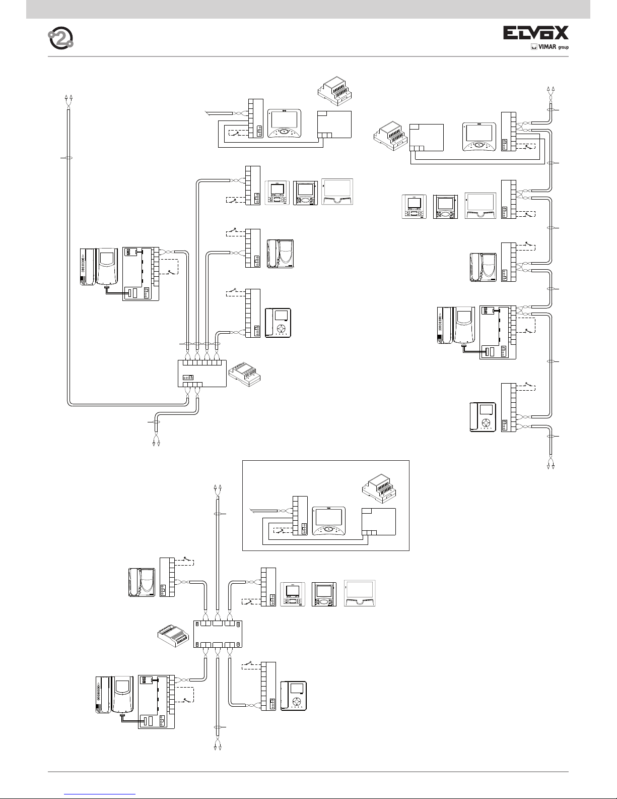
26
C
A
B
1
E+
FP
E-
2
M
CH
+12
21
12
1
2
5
4
6P
+
-
6S
T1
T2
C
VIDEO
T4
A
B
T3
M
V3
A
C
B
4
12
2
3
1
13
OUT
IN
2A OUT 1A2B 1B
4B3B 4AIN3A
T2
T3 T4
TOUT
100
50
B
A
C
E-
2
2
1
E+
1
12V
CH
FP
M
C
A
B
1
E+
FP
E-
2
M
CH
+12
+I+U-
PRI
1C 2C2B1A 1B2A
2112
C
13
1
3
2
12
4
V3
M
B
C
A
C
A
B
FP
E-
M
1
E+
2
CH
+12
12
IN
21
OUT
2D1D
BA
C
A
B
1
E+
FP
E-
2
M
CH
+12
+I+U-
PRI
B
A
C
E-
2
2
1
E+
1
12V
CH
FP
M
4
T2
5
6S
T1
2
1
A
T4
+
C
B
VIDEO
T3
6P
4
T2
5
6S
T1
2
1
A
T4
+
C
B
VIDEO
T3
6P
1
2
1
E+
FP
E-
2
M
CH
+12
M
V3
A
C
B
4
12
2
3
1
13
B
A
C
C
A
B
+12
CH
M
2
EFP
E+
1
+I+U-
PRI
21
E-
2
2
1
E+
1
12V
CH
B
A
C
FP
M
X
X
X
X
X
X
X
X
X
N- Art. 692D
N2- Art. 692D/2
K
K
K
K
K
K
K
K
K
K
K
B4
B4
B4
B5
B5
B5
B1
B2
B3
B0
B0
B0
B1
B3 B2
B1
B3
B2
G- Art. 6923
G- Art. 6923
G- Art. 6923
*
*
*
*
*
*
*
*
*
*
*
*
*
Mains
Mains
Mains
K
K
*
B6
K
X
B6
K
B6
*
si638
X
Video door entry system cable riser wiring. The
video door entry units (interphones) can be connected to the cable riser in the following ways:
• in-out connection, without the aid of floor distributors;
• connection with passive distributor type 692D;
• connection with active distributor type 692D/2;
• hybrid connection using the above 3 methods.
In a video installation, device termination must be
carried out using the jumpers (ABC) in the device itself. See the notes below for terminating devices at
the cable riser in accordance with the wiring type.
LEGEND:
B0 - Wide Touch series door entry monitor type 7311
B1 - 7200 series door entry monitor type 7211
B2 - 6600 series door entry monitor
type 6621, 662C, 6721
type 6611, 661C, 6711
B3 - 6800 series door entry monitor
type 6801, type 68MV + 68M1
B4 - Petrarca series door entry monitor
type 6029/C + 6209 + 6145
type 6029 + 6209 + 6145
B5 - Giotto series door entry monitor
type 6329, 6329/C
B6- Tab series door entry monitor
type7529, 7529/D
G - Additional power supply unit type 6923
N - Distributor type 692D
K - Door call button
X- Cable type 732H, 732I (Twisted Pair)
Monitor cable riser
Monitor cable riser
Monitor cable riser
*
CONNECTION OF MONITORS WITH AND WITHOUT FLOOR DISTRIBUTOR TYPE 692D AND 692D/2 (REF. si638).
Page 27
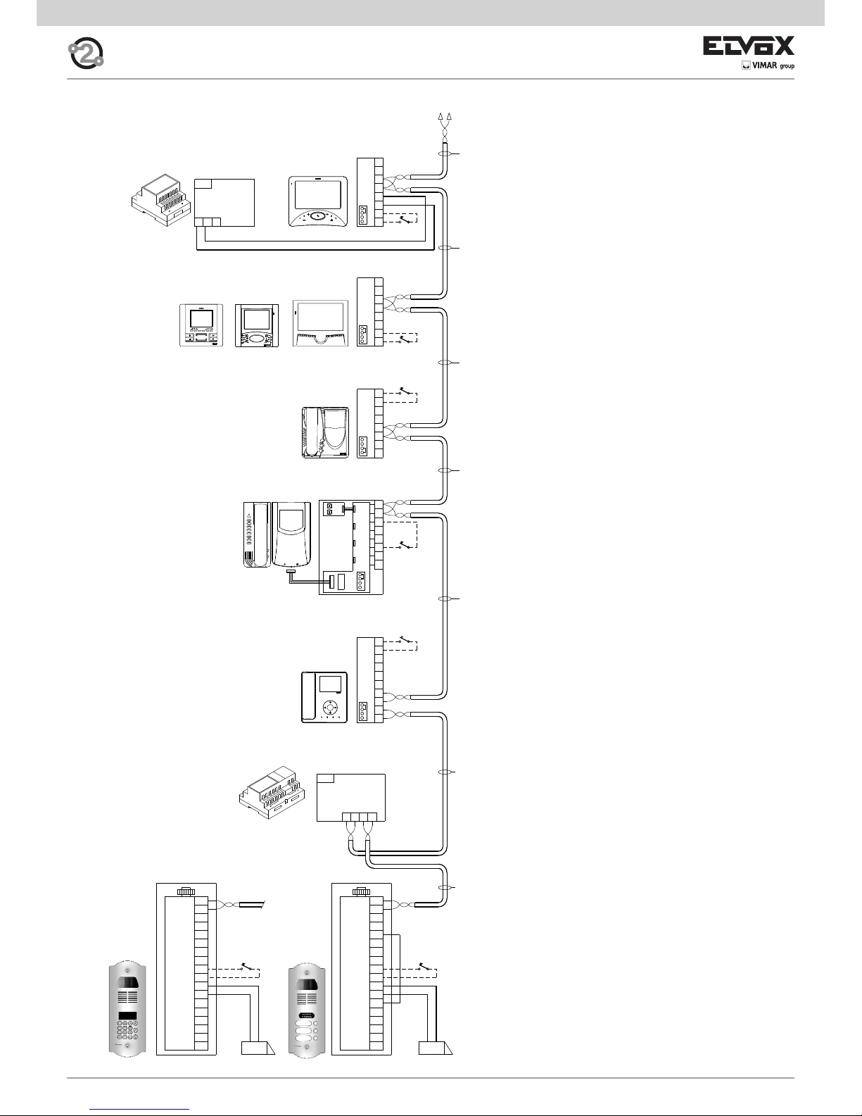
27
EXT+
EXT-
M
PA
X
VLED
B1
B2
S+
S-
F2
F1
SR
-L
+12V
M
M
CA
EXT+
EXT-
M
PA
X
VLED
B1
B2
S+
S-
F2
F1
SR
-L
+12V
M
M
CA
B112B2
PRI
4
T2
5
6S
T1
2
1
A
T4
+
C
B
VIDEO
T3
6P
1
2
1
E+
FP
E-
2
M
CH
+12
M
V3
A
C
B
4
12
2
3
1
13
B
A
C
C
A
B
+12
CH
M
2
EFP
E+
1
+I+U-
PRI
E-
2
2
1
E+
1
12V
CH
B
A
C
FP
M
3
2
1
6
9
4
5
7
8
R
0
C
X
R
F- Art. 6922
B2
B3
B1
B4
B5
G- Art. 6923
B0
X
X
X
X
X
X
D0
P
L
D0
D
D
L
*
*
*
*
Mains
Mains
P
K
K
K
K
X
K
B6
*
SINGLE AND MULTIPLE RESIDENCE VIDEO DOOR ENTRY SYSTEM WITH PETRARCA, GIOTTO AND 6600 SERIES VIDEO INTERPHONES AND ONE VIDEO ENTRANCE PANEL (REF. si433).
Monitor cable riser
B0 - Monitor series Wide touch type 7311
B1 - Monitor series 7200 type 7211
B2 - Monitor series 6600
type 6621, 662C, 6721
type 6611, 661C, 6711,
type 6xxx/F
B3 - Monitor series 6800
type 6801, type 68MV + 68M1
B4 - Monitor series Petrarca
type 6029/C + 6209 + 6145
type 6029 + 6209 + 6145
B5 - Monitor series Giotto
type 6329, 6329/C
B6- Tab series door entry monitor
type7529, 7529/D
D - Video entry panel with push-buttons
F - Power supply type 6922
G - Additional power supply type 692S
K - Push-button for outdoor call
L - 12 V ~ electric lock
P - Lock release control
X - Cable type 732H, 732I (Two twisted wires)
Page 28

28
2C 1D 2D1C2B1B2A1A
21122112
+
PRI
B221B1
1C 2C2B1A 1B2A
2112
C
2D1D
BA
1
22
1
2
1
CA
M
M
+12V
-L
SR
F1
F2
S-
S+
B2
B1
VLED
X
PA
M
EXT-
EXT+EXT+
EXT-
M
PA
X
VLED
B1
B2
S+
S-
F2
F1
SR
-L
+12V
M
M
CA CA
M
M
+12V
-L
SR
F1
F2
S-
S+
B2
B1
VLED
X
PA
M
EXT-
EXT+
4
T2
5
6S
T1
2
1
A
T4
+
C
B
VIDEO
T3
6P
1
2
1
E+
FP
E-
2
M
CH
+12
M
V3
A
C
B
4
12
2
3
1
13
B
A
C
C
A
B
+12
CH
M
2
E-
FP
E+
1
+I+U-
PRI
E-
2
2
1
E+
1
12V
CH
B
A
C
FP
M
R
3
2
1
6
9
4
5
7
8
R
0
C
X
R R
D0
P
L
D0
F- Art. 6922
D
P
D
Mains
K
K
N2Art. 692D/2
J- Art. 692C
X
X
X
X
X
X
X
B1
B3
B0
*
*
K
L
*
*
K
B2
B6
B4
B5
*
K
*
G- Art. 6923
Mains
P
L
X
X
X
X
X
D
D
WIRING DIAGRAM FOR “TWO WIRE ELVOX” VIDEO INTERPHONE INSTALLATIONS WITH TWO OR MORE MONITOR
RISERS WITH DISTRIBUTORS TYPE 692D/2 (SI424).
Monitor cable riser
B0 - Monitor series Wide touch type 7311
B1 - Monitor series 7200 type 7211
B2 - Monitor series 6600
type 6621, 662C, 6721
type 6611, 661C, 6711,
type 6xxx/F
B3 - Monitor series 6800
type 6801, type 68MV + 68M1
B4 - Monitor series Petrarca
type 6029/C + 6209 + 6145
type 6029 + 6209 + 6145
B5 - Monitor series Giotto
type 6329, 6329/C
B6- Tab series door entry monitor
type7529, 7529/D
D - Video entry panel with push-buttons
D0 - Video entry panel with alphanumeric display
F - Power supply type 6922
J - Concentrator type 692C
K - Push-button for outdoor call
L - 12 V ~ electric lock
N2 - Active video distributor type 692D/2
P - Lock release control
X - Cable type 732H, 732I (Two twisted wires)
Page 29
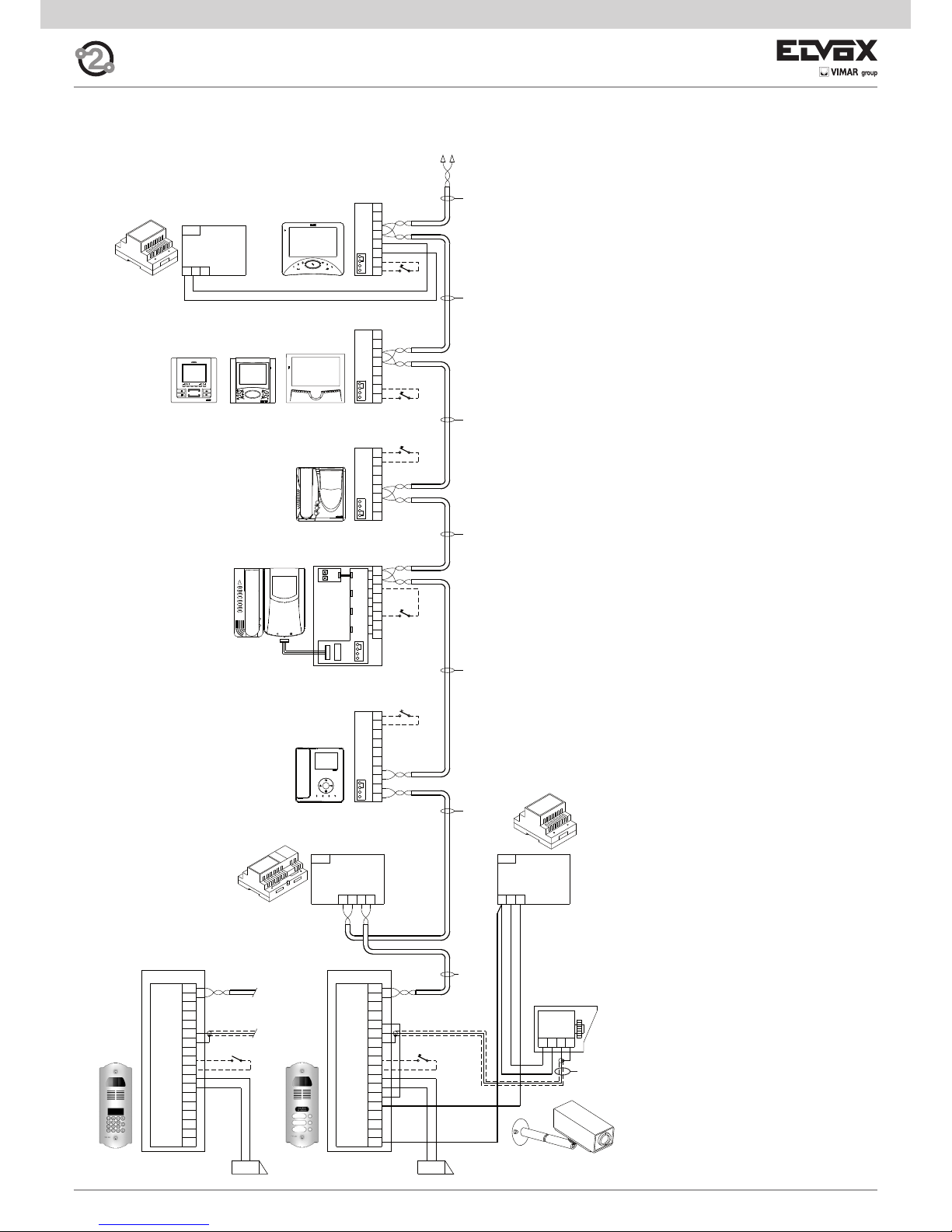
29
CA
M
M
+12V
-L
SR
F1
F2
S-
S+
B2
B1
VLED
X
PA
M
EXT-
EXT+
PRI
B221B1
CA
M
M
+12V
-L
SR
F1
F2
S-
S+
B2
B1
VLED
X
PA
M
EXT-
EXT+
MV-+T
-L-+U
PRI
4
T2
5
6S
T1
2
1
A
T4
+
C
B
VIDEO
T3
6P
1
2
1
E+
FP
E-
2
M
CH
+12
M
V3
A
C
B
4
12
2
3
1
13
B
A
C
C
A
B
+12
CH
M
2
EFP
E+
1
+I+U-
PRI
E-
2
2
1
E+
1
12V
CH
B
A
C
FP
M
88888888
*
8
7
R
0
4
1
2
5
9
C
3
6
K
K
F- Art. 6922
C
P
L
C
C0
P
L
C0
S- Art. 6982
M1
K
Coax 75 ohm
X
X
X
X
X
B4
B5
*
*
*
Mains
Mains
X
G- Art. 6923
Mains
B0
B1
B2
B3
*
K
X
B6
*
K
B0 - Monitor series Wide touch type 7311
B1 - Monitor series 7200 type 7211
B2 - Monitor series 6600
type 6621, 662C, 6721
type 6611, 661C, 6711,
type 6xxx/F
B3 - Monitor series 6800
type 6801, type 68MV + 68M1
B4 - Monitor series Petrarca
type 6029/C + 6209 + 6145
type 6029 + 6209 + 6145
B5 - Monitor series Giotto
type 6329, 6329/C
B6- Tab series door entry monitor
type 7529, 7529/D
C - Audio entry panel with push-buttons
C0 - Audio entry panel with alphanumeric display
F - Power supply type 6922
K - Push-button for outdoor call
L - 12 V ~ electric lock
M1 - 12 V C.C.T.V. external camera
max current 250mA intermittent cycle or
150mA continuous cycle
P - Lock release control
S - Additional power supply type 6982
X - Cable type 732H, 732I (Two twisted wires)
Monitor cable riser
VIDEO ENTRANCE PANEL SYSTEM FOR SINGLE AND TWIN RESIDENCE WITH MONITORS SERIES PETRARCA,
GIOTTO, 6600, ONE ENTRANCE PANEL WITH EXTERNAL CAMERA IN B/W (Ref. SI367).
Page 30
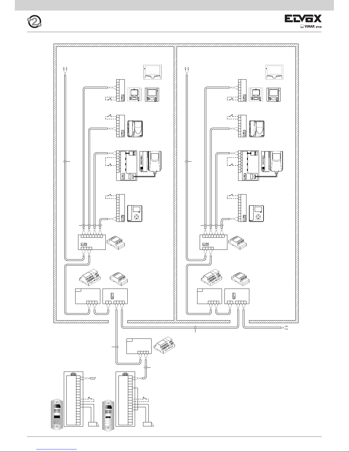
30
EXT+
EXT-
M
PA
X
VLED
B1
B2
S+
S-
F2
F1
SR
-L
+12V
M
M
CA
1
2
BUS D
12
PRI
B221B1
BUS P
2112
B
A
C
D
CA
M
M
+12V
-L
SR
F1
F2
S-
S+
B2
B1
VLED
X
PA
M
EXT-
EXT+
B112B2
PRI
D
C
A
B
2112
BUS P
B112B2
PRI
21
BUS D
21
OUT
21
OUT
VIDEO
B
A
C
T3
T4
T2
T1
6S
+
6P
4
5
2
1
1C 2C2B1A 1B2A
2112
C
13
1
3
2
12
4
V3
M
B
C
A
C
A
B
FP
E-
M
1
E+
2
CH
+12
2D1D
BA
B
A
C
E-
2
2
1
E+
1
12V
CH
FP
M
VIDEO
B
A
C
T3
T4
T2
T1
6S
+
6P
4
5
2
1
1C 2C2B1A 1B2A
2112
C
13
1
3
2
12
4
V3
M
B
C
A
C
A
B
FP
E-
M
1
E+
2
CH
+12
2D1D
BA
B
A
C
E-
2
2
1
E+
1
12V
CH
FP
M
3
2
1
6
9
4
5
7
8
R
0
C
X
R
D0
P
L
D0
D
P
L
D
F- Art. 6922
F- Art. 6922
K
K
K
K
K
K
I- Art. 692S
X
K
X
X
X
X
B4
B5
B5
B3
B4
*
*
*
*
*
*
*
Mains
Mains
X
B2
B1
*
B6
B3
B2
B1
K
B6
I- Art. 692S
N2Art. 692D/2
N2Art. 692D/2
X
F- Art. 6922
Mains
*
*
SINGLE AND MULTIPLE RESIDENCE VIDEO DOOR ENTRY SYSTEM WITH INTERCOMMUNICATING MONITORS (REF.
si611).
B0 - Monitor series Wide touch type 7311
B1 - Monitor series 7200 type 7211
B2 - Monitor series 6600
type 6621, 662C, 6721
type 6611, 661C, 6711,
type 6xxx/F
B3 - Monitor series 6800
type 6801, type 68MV + 68M1
B4 - Monitor series Petrarca
type 6029/C + 6209 + 6145
type 6029 + 6209 + 6145
B5 - Monitor series Giotto
type 6329, 6329/C
B6- Tab series door entry monitor
type 7529, 7529/D
D - Video entry panel with push-buttons
D0 - Video entry panel with alphanumeric display
F - Power supply type 6922
I - Separator type 692S
K - Push-button for outdoor call
L - 12 V ~ electric lock
P - Lock release control
X - Cable type 732H, 732I (Two twisted wires)
Monitor cable riser
Monitor cable riser
Page 31
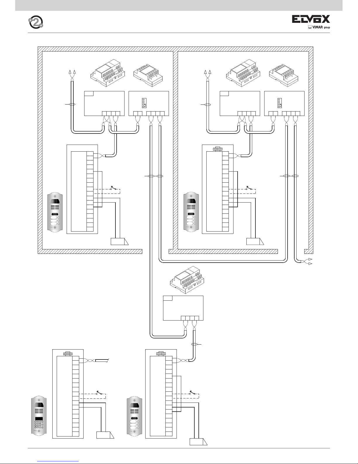
31
1
2
M
PA
X
B1
B2
S+
S-
F2
F1
SR
-L
M
M
CA
EXT+
EXT-
VLED
+12V
BUS D
12
PRI
B221B1
BUS P
2112
B
A
C
D
2
11
2
D
C
A
B
2112
BUS P
B112B2
PRI
21
BUS D
B1
EXT-
EXT+
B2
X
PA
M
M
S+
+12V
S-
CA
SR
F1
F2
M
-L
VLED
CA
M
M
+12V
-L
SR
F1
F2
S-
S+
B2
B1
VLED
X
PA
M
EXT-
EXT+
B112B2
PRI
EXT+
EXT-
M
PA
X
VLED
B1
B2
S+
S-
F2
F1
SR
-L
+12V
M
M
CA
3
2
1
6
9
4
5
7
8
R
0
C
X
R
D0
P
L
D0
D
P
L
D
F- Art. 6922
F- Art. 6922
I- Art. 692S
ID=2
I- Art. 692S
F- Art. 6922
ID=2
C
C
P
L
ID=3
P
L
ID=1
D
D
ID=1
X
X
X
X
X
*
*
Mains
Mains
Mains
VIDEO DOOR ENTRY SYSTEM FOR BUILDING COMPLEX (REF. SI380).
Monitor cable riser
Monitor cable riser
C - Audio entry panel with push-buttons
C0 - Audio entry panel with alphanumeric display
D - Video entry panel with push-buttons
D0 - Video entry panel with alphanumeric display
F - Power supply type 6922
I - Separator type 692S
K - Push-button for outdoor call
L - 12 V ~ electric lock
P - Lock release control
X - Cable type 732H, 732I (Two twisted wires)
Cable riser
Page 32

32
2C 1D 2D1C2B1B2A1A
21122112
+
2C 1D 2D1C2B1B2A1A
21122112
+
B1
EXT-
EXT+
B2
X
PA
M
M
S+
+12V
S-
CA
SR
F1
F2
M
-L
VLEDVLED
-L
M
F2
F1
SR
CA
S-
+12V
S+
M
M
PA
X
B2
EXT+
EXT-
B1
VLED
-L
M
F2
F1
SR
CA
S-
+12V
S+
M
M
PA
X
B2
EXT+
EXT-
B1
BUS D
12
PRI
B221B1
BUS P
2112
B
A
C
D
2
1
S+
S-
F2
F1
SR
-L
+12V
M
M
CACA
M
M
+12V
-L
SR
F1
F2
S-
S+
EXT+
EXT-
M
PA
X
VLED
B1
B2B2
B1
VLED
X
PA
M
EXT-
EXT+
B112B2
PRI
EXT+
EXT-
M
PA
X
VLED
B1
B2
S+
S-
F2
F1
SR
-L
+12V
M
M
CACA
M
M
+12V
-L
SR
F1
F2
S-
S+
B2
B1
VLED
X
PA
M
EXT-
EXT+
1
2
D
C
A
B
2112
BUS P
B112B2
PRI
21
BUS D
+
-
2112 2112
1A 2A 1B 2B 1C 2D1D2C
EXT+
EXT-
M
PA
X
VLED
B1
B2
S+
S-
F2
F1
SR
-L
+12V
M
M
CA
2
1
2
1
2
1
2
1
2
1
AB
1D 2D
C
2112
2A 1B1A 2B 2C1C
AB
1D 2D
C
212C12
2A 1B1A 2B 2C1C
3
2
1
6
9
4
5
7
8
R
0
C
X
R
P
L
D0
D0
F- Art. 6922
F- Art. 6922
I- Art. 692S
ID=2
I- Art. 692S
F- Art. 6922
ID=4
P
L
ID=1
D
D
ID=1
J- Art. 692C
P
L
D
ID=2
P
L
D
ID=3
P
L
J- Art. 692C
ID=5
P
L
D
D
J- Art. 692C
ID=6
P
L
C
C
ID=7
P
L
C
C
X
X
X
X
X
X
X
X
X
XX
*
*
Mains
Mains
Mains
X
X
N2Art. 692D/2
ID=4
N2Art. 692D/2
D
D
D
D
VIDEO DOOR ENTRY SYSTEM FOR BUILDING COMPLEX WITH THREE MAIN ENTRANCE PANELS AND TWO STAIRWAY PANELS PER APARTMENT BLOCK (AUDIO AND VIDEO) (REF. SI382).
C - Audio entry panel with push-buttons
C0 - Audio entry panel with alphanumeric display
D - Video entry panel with push-buttons
D0 - Video entry panel with alphanumeric display
F - Power supply type 6922
I - Separator type 692S
J - Concentrator type 692C
L - 12 V ~ electric lock
N2 - Active video distributor type 692D/2
P - Lock release control
X - Cable type 732H, 732I (Two twisted wires)
Monitor cable riser
Monitor cable riser
Page 33

33
ELVOX
1
2
EXT+
EXT-
M
PA
X
VLED
B1
B2
S+
S-
F2
F1
SR
-L
+12V
M
M
CA
+
-
ELVOX ELVOX ELVOX
Sign lighting circuit
for 15 names (for
panel Art. 122N,
123N).
ELVOX
ELVOX ELVOX ELVOX ELVOX
1
2
EXT+
EXT-
M
PA
X
VLED
B1
B2
S+
S-
F2
F1
SR
-L
+12V
M
M
CA
ELVOX ELVOX ELVOX
ELVOX
ELVOX ELVOX ELVOX ELVOX
1
2
EXT+
EXT-
M
PA
X
VLED
B1
B2
S+
S-
F2
F1
SR
-L
+12V
M
M
CA
PRI
DBAC+U-+I
ELVOX ELVOX ELVOX
Art. 6582
ELVOX ELVOX ELVOX
1
2
EXT+
EXT-
M
PA
X
VLED
B1
B2
S+
S-
F2
F1
SR
-L
+12V
M
M
CA
+
-
+
-
+
-
+
-
+
-
VARIANT
Electronic unit with alphanumeric keyboard, backlit sign with house
number (panel Art. 12N4, 12N3, 12N2, 12N1)
VARIANT
Electronic unit with alphanumeric keyboard (up to 8 modules type
805N, 80PN).
Monitor cable riser
Perform wiring
Sign lighting circuit
for 15 names (for
panel Art. 122N,
123N).
Perform wiring
Monitor cable riser
VARIANT
Electronic unit with additional button modules (up to 4 modules type 12TS, 8051, 8052, 8054, 8042, 8044, 8046, 8048)
Additional button module
12TS, 8051, 8052,
8053, 8054, 8042
8044, 8046, 8048
Perform VLED/+12
wiring
Monitor cable riser
VARIANT
Electronic unit with additional button modules (from 5 to 30 modules type 12TS, 8051, 8052, 8054, 8042, 8044, 8046, 8048)
Additional button module
12TS, 8051, 8052,
8053, 8054, 8042
8044, 8046, 8048
Mains
Add power
supply
NOTE: type 12TS for 1200 and 1300 series
NOTE: type 805x for type 89F3/… and 89F5…, are sold complete with
8000 series plate.
Monitor cable riser
Page 34

34
ELVOX ELVOX ELVOX ELVOX
ELVOX ELVOX ELVOX ELVOX
1
2
PRI
DBAC+U-+I
+
-
+
-
+
-
+
-
+
-
PRI
DBAC+U-+I
PRI
DBAC+U-+I
EXT+
EXT-
M
PA
X
VLED
B1
B2
S+
S-
F2
F1
SR
-L
+12V
M
M
CA
Mains
Art. 6582
Mains Mains
Art. 6582
Art. 6582
VARIANT
Connection of additional power supply type 6923.
.
VARIATION
Connection of auxiliary functions F1 and F2
Functions F1 and F2 can be activated from the interphones and video interphones by connecting a relay
type 0170/001 to terminals F1 and F2 of the entrance
panel.
P
L
Art. 732H
C/D
Q -
Art. 170/001
Q -
Art. 170/001
1
2
EXT+
EXT-
M
PA
X
VLED
B1
B2
S+
S-
F2
F1
SR
-L
+12V
M
M
CA
1 2 3 4 5 5 4 3 2 1
P
L
QArt. 0170/001
L
P
G - Art. 6923
Art. 732H
C/D
C/D
CA
M
M
+12V
-L
SR
F1
F2
S-
S+
B2
B1
VLED
X
PA
M
EXT-
EXT+
2
1
PRI
-+U
+I
123
456
789
0
ABC DEF
GHI JKL MNO
PQRS TUV WXYZ
.,;
R
CANC
G- Art. 6923
P
L
C0/
D0
C0/D0
Mains
X
VARIANTE
Connection of lock with additional power supply
To open high power locks, an external transformer may be used, which powers the lock by
means of a relay type 0170/001, connected to terminals +12V/SR of the entrance panel. The lock
opening time is the same as that set on terminals
S+/S-.
L
P
Art. 732H
C/D
Q -
Art. 170/001
R -
Art. 832/030
5 4 3 2 1
PRI
15 0
CA
M
M
+12V
-L
SR
F1
F2
S-
S+
B2
B1
VLED
X
PA
M
EXT-
EXT+
2
1
P
L
RArt. 0832/030
QArt. 0170/001
A
T
X
C0/D0
A
T
C0/
D0
X
QArt. 0170/001
C0/
D0
Mains
C/C0 - Targa esterna audio a pulsanti o alfanumerica
D/D0 - Targa esterna video a pulsanti o alfanumerica
L - 12 V ~ electric lock
P - Comando apriporta
Q - Relay Art. 0170/001
X - Cavo Art. 732H, 732I (Due Fili Twistati)
C0/D0
ELVOX ELVOX ELVOX ELVOX
1
2
EXT+
EXT-
M
PA
X
VLED
B1
B2
S+
S-
F2
F1
SR
-L
+12V
M
M
CA
PRI
DBAC+U-+I
+
-
+
-
+
-
+
-
+
-
VARIANT
Electronic unit with alphanumeric keyboard (over 60 modules type
805N, 80PN).
VARIANT
Electronic unit with alphanumeric keyboard (with 9 to 60 modules
type 805N, 80PN).
Monitor cable riser
Monitor cable riser
type 6582
Sign lighting circuit
for 15 names (for
panel Art. 122N,
123N).
Sign lighting circuit for 15 names
(for panel Art.
122N, 123N).
F1
function
Load
maximum
230V~ 3A
F2
function
Load
maximum
230V~ 3A
C0 - Audio entry panel with alphanumeric display
D0 - Video entry panel with alphanumeric display
G - Additional power supply type 6923
L - 12 V ~ electric lock
P - Lock release control
Q - Relay Art. 0170/001
R - Transformer Art. 0832/030
X - Cable Art. 732H, 732I (Two twisted wires)
C/C0 -Audio entry panel with alphanumeric display
D/D0 -Video entry panel with alphanumeric display
L - 12 V ~ electric lock
P - Lock release control
X - Cable Art. 732H, 732I (Two twisted wires)
Add power supply for the first
60 modulesi
Add power
supply for the
next 60 modules
Add power
supply for the
next 60 modules
Page 35

35
A
C
B
1
2
4
5
6S
2
1
6P
K
K
1
T2
5
T3
6S
T1
2
4
T4
A
C
B
+
VIDEO
6P
1
2
K
K
2
1
M
4
12
2
3
1
V3
13
A
C
B
K
K
2
1
+12
CH
M
2
EFP
E+
1
C
A
B
K
2
1
+12
CH
M
2
EFP
E+
1
C
A
B
K
B1
B2
B3
A1
A2
A3
B5
C
A
B
+12
CH
M
2
E-
FP
E+
1
K
+I+U-
PRI
G- Art. 6923
B0
Mains
K
2
1
2
1
2
2
1
1
12V
CH
B
A
C
FP
M
A4
K
2
1
2
1
E-
2
2
1
E+
1
12V
CH
B
A
C
FP
M
B6
K
5
2
2
1
4
1
6S
6P
B
A
C
K
2
1
A0
K
VARIANT
Wiring diagram for additional mechanical doorbells.
Additional doorbells operating at 12V can be connected by using relay type 0170/101 connected as shown in the diagram.
A0 - Interphone type 6901, type 6901/D
A1 - Interphone series Petrarca type 6209
A2 - Interphone series 6600
type 6601/AU, 660C/AU, 6701/AU
type 6611/AU, 661C/AU, 6711/AU, type 6xxx/AUF
A3 - Interphone series 8870 type 8879
A4 - Interphone series tab type 7509, 7509/D
B0 - Monitor series Wide touch type 7311
B1 - Monitor series 7200 type 7211
B2 - Monitor series 6600
type 6621, 662C, 6721
type 6611, 661C, 6711, type 6xxx/F
B3 - Monitor series 6800
type 6801, type 68MV + 68M1
B4 - Monitor series Petrarca
type 6029/C + 6209 + 6145
type 6029 + 6209 + 6145
B5 - Monitor series Giotto type 6329, 6329/C
B6- Tab series door entry monitor type 7529, 7529/D
K - Push-button for outdoor call
X - Cable type 732H, 732I (Two twisted wires)
Page 36

36
8574PRI
2
1
1
E+
FP
E-
2
M
CH
+12
B
A
C
+I+U-
PRI
B
C
A
8574PRI
2
1
6P
1
2
6S
5
4
8574PRI
4
A
T2
T4
T3
5
6S
+
6P
C
B
VIDEO
T1
2
1
2
1
Mains
Mains
8 5 7 4 PRI
2
1
2
1
13
V3
1
3
2
12
4
M
B
C
A
Mains
8 5 7 4 PRI
2
1
1
E+
FP
E-
2
M
CH
+12
B
A
C
Ringtone
Art. 860A
Mains
8 5 7 4 PRI
2
1
1
E+
FP
E-
2
M
CH
+12
B
A
C
Mains
B1
B2
B3
A1
A3
A2
B5
G- Art. 6923
B0
Ringtone
Art. 860A
Ringtone
Art. 860A
Ringtone
Art. 860A
Ringtone
Art. 860A
Ringtone
Art. 860A
Mains
Mains
2
1
2
1
8574PRI
E-
2
2
1
E+
1
12V
CH
B
A
C
FP
M
B6
K
Ringtone
Art. 860A
Mains
2
1
2
1
8574PRI
2
2
1
1
12V
CH
B
A
C
FP
M
A4
K
Ringtone
Art. 860A
Mains
8574PRI
5
2
2
1
4
1
6S
6P
B
A
C
2
1
A0
Ringtone
Art. 860A
Mains
VARIANT
Wiring diagram of additional electronic ringtone type 860A.
The electronic ringtone type 860A features a two or three-note ringtone connected between terminal 7 and terminal 8. The ringtone must be powered at
mains voltage. The doorbell rhithm follows the call push- button pressure.
A0 - Interphone type 6901, type 6901/D
A1 - Interphone series Petrarca type 6209
A2 - Interphone series 6600
type 6601/AU, 660C/AU, 6701/AU
type 6611/AU, 661C/AU, 6711/AU, type 6xxx/AUF
A3 - Interphone series 8870 type 8879
A4 - Interphone series tab type 7509, 7509/D
B0 - Monitor series Wide touch type 7311
B1 - Monitor series 7200 type 7211
B2 - Monitor series 6600
type 6621, 662C, 6721
type 6611, 661C, 6711, type 6xxx/F
B3 - Monitor series 6800
type 6801, type 68MV + 68M1
B4 - Monitor series Petrarca
type 6029/C + 6209 + 6145
type 6029 + 6209 + 6145
B5 - Monitor series Giotto type 6329, 6329/C
B6- Tab series door entry monitor type 7529, 7529/D
G - Additional power supply type 692G
X - Cable type 732H, 732I (Two twisted wires)
Page 37

37
A
C
B
1
2
4
5
6S
2
1
6P
15 5243
RC
-
+
C1
1C
+
-
RC
342515
1
22
T1
VIDEO
B
C
6P
+
-
6S
5
T3
T4
T2
A
4
1
Relay
Art. 0170/101
Relay
Art. 0170/101
1
2
13
V3
1
3
2
12
4
M
15 5243
RC
-
+
C1
B
C
A
Relay
Art. 0170/101
1
2
+12
CH
M
2
E-
FP
E+
1
15 5243
RC
-
+
C1
C
A
B
Relay
Art. 0170/101
1
2
+12
CH
M
2
EFP
E+
1
15 5243
RC
-
+
C1
C
A
B
Relay
Art. 0170/101
B1
B2
B3
B5
A1
A3
2
1
2
1
15 5243
RC
-
+
C1
E-
2
2
1
E+
1
12V
CH
B
A
C
FP
M
B6
K
Relay
Art. 0170/101
2
1
2
1
15 5243
RC
-
+
C1
2
2
1
1
12V
CH
B
A
C
FP
M
A6
K
Portata
3A 230V
Relay
Art. 0170/101
15 5243
RC
-
+
C1
5
2
2
1
4
1
6S
6P
B
A
C
2
1
Portata 3A 230V
A0
VARIANTE
Schema di collegamento delle suonerie supplementari a timpano.
Si possono collegare suonerie supplementari funzionanti da 12 V alla tensione di mains, utilizzando il relay Art. 0170/101 collegandole come illustrato nello
schema.
A2
Relay
Art. 0170/101
Portata
3A 230V
A0 - Interphone type 6901, type 6901/D
A1 - Interphone series Petrarca type 6209
A2 - Interphone series 6600
type 6601/AU, 660C/AU, 6701/AU
type 6611/AU, 661C/AU, 6711/AU, type
6xxx/AUF
A3 - Interphone series 8870 type 8879
A4 - Interphone series tab type 7509, 7509/D
B0 - Monitor series Wide touch type 7311
B1 - Monitor series 7200 type 7211
B2 - Monitor series 6600
type 6621, 662C, 6721
type 6611, 661C, 6711, type 6xxx/F
B3 - Monitor series 6800
type 6801, type 68MV + 68M1
B4 - Monitor series Petrarca
type 6029/C + 6209 + 6145
type 6029 + 6209 + 6145
B5 - Monitor series Giotto type 6329, 6329/C
B6- Tab series door entry monitor type 7529,
7529/D
G - Additional power supply type 6923
X - Cable type 732H, 732I (Two twisted wires)
Ringtone power supply
Additional ringtone
Ringtone power supply
Additional ringtone
Ringtone power supply
Additional ringtone
Ringtone power supply
Additional ringtone
Ringtone power supply
Additional ringtone
Ringtone power supply
Additional ringtone
Ringtone power supply
Additional ringtone
Additional ringtone
Ringtone power supply
Page 38

38
6P
T3
VIDEO
B
C
+
-
T4
A
1
2
T1
6S
5
T2
4
4
T2
5
6S
T1
2
1
A
T4
+
C
B
VIDEO
T3
6P
C
VIDEO
6P
T3
+
-
T4
A
1
2
T1
6S
5
T2
4
B
+U-
PRI
21
1
2
+I
G- Art. 6923
Mains
G- Art. 6923
2
1
1
2
PRI
-
+U
M
4
12
2
3
1
V3
13
13
V3
1
3
2
12
4
M
13
V3
1
3
2
12
4
M
+I
A
C
B
B
C
A
B
C
A
Mains
2
1
1
2
PRI
-+U
+12
CH
M
2
EFP
E+
1
1
E+
FP
E-
2
M
CH
+12
+12
CH
M
2
EFP
E+
1
+I
C
A
B
B
A
C
C
A
B
G- Art. 6923
Mains
X
X
X
X
X
X
X
X
X
B1
B2
B3
B5
B5
B5
B4
B4
B4
1
2
C
A
B
+12
CH
M
2
EFP
E+
1
15 5243
RC
-
+
C1
+I+U-
PRI
G- Art. 6923
B0
Relay
Art. 0170/101
Alimentazione suoneria
Suoneria supplementare
Mains
VARIANT
Wiring diagram with simultaneous switch-on of two or more monitors with power supply type 6923.
The power supply unit Type 6922 can simultaneously power one video
entrance panel and two monitors Type 6029, 6029/C, 6611, 6621, 661C,
662C, 6711, 6721 switched on.
With a larger number of monitors switched on simultaneously, additional power supply type 6923 must be used after the 2nd monitor. One
power supply type 6923 must be used per additional monitor.
B0 - Monitor series Wide touch type 7311
B1 - Monitor series 7200 type 7211
B2 - Monitor series 6600
type 6621, 662C, 6721
type 6611, 661C, 6711, type 6xxx/F
B3 - Monitor series 6800
type 6801, type 68MV + 68M1
B4 - Monitor series Petrarca
type 6029/C + 6209 + 6145
type 6029 + 6209 + 6145
B5 - Monitor series Giotto type 6329, 6329/C
K - Push-button for outdoor call
X - Cable type 732H, 732I (Two twisted wires)
Page 39

39
ADDITIONAL SUPPLY VOLTAGES
In “Elvox TWO WIRE ” installations, power supply type 6922 powers all the appliances: entrance panels, interphones, monitors,
concentrators, distributors. When the maximum load of the appliances exceeds the maximum load of the power supply it is necessary to add additional power supplies. The insertion of a
separator with a power supply type 6922 in the installation, split
the appliance charge upstream of the separator from the appliances downstream of the separator.
Power supply type 6923
The additional power supply type 6923 is to be used to power
electronic entrance panels, monitors and concentrators supporting the main power supply type 6922. When there is a lodge
switchboard there must always be installed a power supply type
6923 dedicated to the switchboard. The power supply is required when there are more video entrance panels installed and/or
when there are more monitors turning on simultaneously at the
same call. The power supply can power only a particular appliance: entrance panel or monitor. The tables show when it is
necessary to use a power supply type 6923 according to the
number of entrance panels mounted in the installation and according to the number of interphones or monitors activated/turned
on simultaneously.A power supply type 6922 powers up to 3
units simultaneously, besides them it is necessary a power supply type 6923 for each unit added. If the consumption exceeds
the 3 units, use one power supply type 6923 to power the monitors and the entrance panels and leave the power supply type
6922 dedicated to other appliances.
Consumption for unit:
1 video entrance panels switched on = 1 unit
1 audio entrance panel switched on = 1/2 unit
1 entrance panel not switched on/engaged = 1/4 unit
1 monitor switched on = 1 unit
1 concentrator type 692C = 1/3 unit
1 active distributor type 692D/2 = 1/20 unit
1 separator type 692S = 1/40 unit
Attention: when using active distributors, it is not possible to
power them separately with the additional power supply.
Example of audio and video installation in a building:
A – Interphone
B – Video interphone
C – Electronic audio entrance panel
D – Electronic video entrance panel
F – Power supply type 6922
I – Separator type 692S
J - Concentrator type 692C
L – Door lock
N – Video distributor type 692D
N2 – Video distributor type 692D/2
Example of video entrance panel system for building complex.
The hereby wiring diagrams are reference examples for the tables to follow (Tab. A, Tab. B and Tab. C) for the insertion of the
additional power supply type 6923.
Tab . A
Tab . B
Tab . C
N2
2
2
22
2
2
A
B
B
2
2
L
2
I
2
2
2
2
2
I
2
2
F
2
2
C
L
L
F
2
D
D
2
C
L
2
2
L
D
J
2
2
J
2
F
2
2 2
N
N
L
2
D
Tab . A
Tab . B
2
2
22
2
2
A
B
B
2
2
2
2
2
2
2
2
F
2
2
C
L
L
F
D
2
C
L
2
2
L
D
J
2
N
N
Page 40

40
Number of audio entrance panels con-
nected in parallel.
1 active and the others engaged
Number of interphones inserted with the
same call
Number of power supplies Type 6923
From 1 to 10 From 1 to 8 0
From 11 to 15 From 1 to 8
From 1 to 5 (one type 6923 added for each entrance panel from 11th.
to 15th.)
Table for audio entrance panel systems with 1 or more entrance panels connected in parallel and one audio riser.
Table for video installations with 1 or more entrance panels connected in parallel and a video riser.
Table B.
Number of audio
entrance panels
connected in pa-
rallel,
1 active and the
other engaged
Number of video
entrance panels
connected in pa-
rallel,
1 active and the
others engaged
Number of
concentrators
(Type 692C)
Number of inter-
phones inserted
with the same call
Number of monitors
turned on simultaneou-
sly at the same call.
Number of power supplies Type 6923
0 1 0 From 1 to 8 From 1 to 2 0
0 1 0 From 1 to 8 From 3 to 8
From 1 to 6 (one type 6923 added for each monitor
from the 3rd. to the 8th.)
0 From 2 to 3 1 From 1 to 8 1 0
0 From 2 to 3 1 From 1 to 8 From 2 to 3
From 3 to 4 (one type 6923 added for each entrance
panel and for the concentrator)
0 From 2 to 3 1 From 1 to 8 From 2 to 8
From 1 to 7 (on e type 6923 added for each monitor
from the 2nd. to the 8th.)
0 4 1 From 1 to 8 1 1 ( one type 6923 added for the concentrator)
0 4 1 From 1 to 8 From 2 to 8
From 2 to 8 (one type 6923 added for the concentrator
and one 6923 for each monitor from the 2nd to the 8th.)
0 5 2 From 1 to 8 1 2 (one type 6923 added for each concentrator)
0 From 6 to 15 From 2 to 5 From 1 to 8 1
From 6 to 15 (one type 6923 added for each entrance
panel)
0 From 6 to 15 From 2 to 5 From 1 to 8 From 2 to 3
From 8 to 20 (one type 6923 added for each entrance
panel and for each concentrator)
0 From 6 to 15 From 2 to 5 From 1 to 8 From 2 to 8
From 7 to 23 (one type 6923 for each entrance panel,
for each monitor from the 2nd to the 8th.)
2 1 1 From 1 to 8 1 0
2 1 1 From 1 to 8 From 2 to 8
From 1 to 7 (one type 6923 added for each monitor
from the 2nd to the 8th.).
1 2 1 From 1 to 8 1 0
1 2 1 From 1 to 8 From 2 to 8
From 1 to 7 (one type 6923 added for each monitor
from the 2nd to the 8th.).
3 1 1 From 1 to 8 1 1 (one type 6923 added for the concentrator)
1 3 1 From 1 to 8 1 1 (one type 6923 added for the concentrator)
In table Tab B we have forseen that the monitors programmed with the same call code light up all simultaneously.
It is possible to program the monitors (connected in parallel) in such a way that only one lights up at the call, while the other remain switched off. The monitor turned off can be turned on by using the self-start function. This expedient saves you from adding the additional power supplies for the monitors..
Table for audio and video entrance panel systems in building complex with 1 or more entrance panels connected in parallel.
Tab C.
Number of audio
entrance panels
connected in paral-
lel,
1 active and the
other engaged
Number of video
entrance panels
connected in paral-
lel,
1 active and the
others engaged
Number of
concentrators
(Type 692C)
Number of power supplies Type 6923
From 1 a 11 0 0 0
From 12 a 14 0 0 From 1 to 3 (one type 6923 added for each monitor from the 12rd. to the 14th.)
0 From 1 to 6 From 1 to 2 0
0 From 7 to 14 From 2 to 5 From 2 to 13 (one type 6923 added for each monitor from the 7rd. to the 14th.)
From 1 a 3 1 1 0
1 From 1 to 3 1 0
3 4 2 2 (one type 6923 added for each concentrator)
Page 41

41
SAFETY INSTRUCTIONS FOR INSTALLERS
- Carefully read the instructions on this leaflet: they give important information on the safety, use and maintenance of the installation.
- After removing the packing, check the integrity of the set. Packing components (plastic bags, expanded polystyrene etc.) are dangerous for children. Installation must be carried out according to national safety regulations.
- It is convenient to fit close to the supply voltage source a proper ominipolar type switch with 3 mm separation (minimum) between contacts.
- Before connecting the set, ensure that the data on the label correspond to those of the mains.
- Use this set only for the purposes designed, i.e.for electric door-opener systems. Any other use may be dangerous. The manufacturer is not responsible
for damage caused by improper, erroneous or irrational use.
- Before cleaning or maintenance, disconnect the set.
- In case of failure or faulty operation, disconnect the set and do not open it.
- For repairs apply only to the technical assistance centre authorized by the manufacturer.
- Safety may be compromised if these instructions are disregarded.
- Do not obstruct opening of ventilation or heat exit slots and do not expose the set to dripping or sprinkling of water.
- Installers must ensure that manuals with the above instructions are left on connected units after installation, for users' information.
- All items must only be used for the purposes designed.
- WARNING: to avoid the possibility of hurting yourself, this unit must be fixed to the wall according to the installation instructions.
- This leaflet must always be enclosed with the equipment.
Directive 2002/96/EC (WEEE)
The crossed-out wheelie bin symbol marked on the product indicates that at the end of its useful life, the product must be handled separately from
household refuse and must therefore be assigned to a differentiated collection centre for electrical and electronic equipment or returned to the dealer upon purchase of a new, equivalent item of equipment.
The user is responsible for assigning the equipment, at the end of its life, to the appropriate collection facilities.
Suitable differentiated collection, for the purpose of subsequent recycling of decommissioned equipment and environmentally compatible treatment and disposal, helps prevent potential negative effects on health and the environment and promotes the recycling of the materials of which the product is made. For
further details regarding the collection systems available, contact your local waste disposal service or the shop from which the equipment was purchased.
Risks connected to substances considered as dangerous (WEEE).
According to the WEEE Directive, substances since long usually used on electric and electronic appliances are considered dangerous for people and the
environment. The adequate differentiated collection for the subsequent dispatch of the appliance for the recycling, treatment and dismantling (compatible
with the environment) help to avoid possible negative effects on the environment and health and promote the recycling of material with which the product
is compound.
Product is according to EC Directive 2004/108/EC and following norms.
Page 42

42
NOTE:
Page 43

43
NOTE:
Page 44

Via Pontarola, 14/a
35011 Campodarsego PD
Tel. +39 049 920 2511
Fax +39 049 920 2603
www.elvox.com
S6I.89F.4TE RL. 02 13 01
ELVOX - Campodarsego - Italy
 Loading...