

Page 1
Art. 88TK
LETTORE PER TRANSPONDER
PROXIMITY READER
LECTEUR POUR TRANSPONDEUR
TRANSPONDERLESER
LECTOR PARA TRANSPONDEDOR
LEITOR TRANSMISSOR
Cod. S6I.88T.K00 RL. 04 12/2008
Il prodotto è conforme alla direttiva europea 2004/108/CE e successive.
Product is according to EC Directive
2004/108/CE and following norms.
Art. 88TL
Art. 88TM
MANUALE PER IL COLLEGAMENTO E L’USO
INSTALLATION AND OPERATION MANUAL
MANUEL POUR LA CONNEXION ET L’EMPLOI
INSTALLATION UND BEDIENUNGSANLEITUNG
MANUAL PARA EL CONEXIONADO Y EL USO
MANUAL DE INSTALAÇÃO E UTILIZAÇÃO
Page 2

2
DESCRIZIONE
L’art. 88TK è un lettore per chiavi a transponder
art. 88TL, 88TM. Il lettore in presenza di una chiave memorizzata chiude il contatto di un relè presente al suo interno. Il lettore può essere utilizzato
singolarmente o su impianti DigiBus, nei quali è
possibile monitorare le attivazioni del lettore stesso attraverso il software PC DigiBUS Analyzer2 e
DataOrganizer. Le chiavi art. 88TL (tipo tessera)
e 88TM (tipo portachiavi) sono fornite con un proprio codice unico.
Caratteristiche elettriche/funzionali di base:
Numero massimo chiavi a transponder memorizzabili: 150.
Alimentazione : nominali ( 12 Vcc) range di alimentazione (10 .. 14 Vcc).
Potenza max. assorbita: 0,7 Watt.
Distanza di lettura : 10 .. 30 mm; ( in funzione
dell’antenna e del transponder TAG utilizzati ).
Contatto relè (N.A. - normalmente aperto):
24Vc.c./c.a. max , 3A max.
Morsetti:
5: positivo alimentazione (12Vcc).
4: negativo alimentazione.
1: un morsetto di comunicazione seriale verso
centralina esterna (o personal computer tramite l’interfaccia Art. 6952 o Art. 6952/A) o
dispositivo comunque atto a memorizzare
eventuali informazioni relative alla chiave
transponder riconosciuta.
R1-R2:
contatto normalmente aperto (relativo al
relè interno al dispositivo).
INSTALLAZIONE
Da esterno parete
1) Inserire un cacciavite a taglio largo nella fessura ricavata nel lato inferiore del coperchio e
con una semplice rotazione togliere il coperchio copriviti (Fig. 1).
2) Togliere le 2 viti di fissaggio e il coperchio
copri lettore.
3) Fissare il contenitore del lettore in parete (Fig.
2), applicando dei tasselli.
4) Effettuare i collegamenti al corpo del lettore.
DESCRIPTION
Type 88TK is a reader for transponder keys type
88TL, 88TM. The reader in presence of a memorized key closes the contact of a relay present in
the same reader. The reader can be used individually or in DIGIBUS installations, where it is possible to monitor the reader activations through the
software PC DigiBUS Analyzer2 e
DataOrganizer. Keys type 88TL (pass type) and
88TM (key holder type) are supplied with a unique
own code.
Basic electrical/functional features:
Maximum transponder key number that can be
stored: 150.
Supply voltage : nominal (12 VDC) tolerance +/- 2
VDC.
Absorbed max. power: 0,7 Watt.
Reading distance: 10 .. 30 mm; (depending on
the antenna and on TAG transponder used).
Relay contact (N.O. - normally open): 24V
A.C./D.C. max, max 3A.
Terminal block:
5: supply positive (12VDC).
4: supply negative.
1: a terminal of serial communication to an
external control unit (or personal computer
through interface type 6952 or 6952/A) or
a device however fitted to store information
about the recognized transponder key.
R1-R2:
normally open contact (concerning the
internal relay of the device).
INSTALLATION
Surface wall-mounting
1)
Insert a wide-tipped screw driver in the slot placed on the cover lower side and with a simple
rotation remove the screw cover (Fig. 1).
2) Remove the two fixing screws and the reader
cover.
3) Fix the reader housing to the wall (Fig. 2)
using the expansion plugs.
4) Carry out connections to the reader body.
GB
I
Page 3

3
DESCRIPTION
L’art. 88TK est un lecteur pour clés à transpondeur art. 88TL, 88TM. Le lecteur, en présence
d'une clé mémorisée, ferme le contact d'un relais
se trouvant à l'intérieur. Le lecteur peut être utilisé
seul ou sur une installation DigiBus, qui permet
de monitorer les activations du lecteur via le logiciel PC DigiBUS Analyzer2 e DataOrganizer.
Les clés art. 88TL (type carte) et 88TM (type
porte-clés) sont fournies avec un code unique.
Caractéristiques électriques/fonctionnelles de
base:
Nombre maximum de clés à transpondeur
mémorisables: 150.
Alimentation : nominales ( 12 Vcc) plage (10 .. 14
Vcc).
Puissance max. absorbée: 0,7 Watt.
Distance de lecture: 10 .. 30 mm ; (en fonction de
l’antenne et du transpondeur TAG utilisés).
Contact relais (N.O. - normalement ouvert) :
24Vcc max , 3A max.
Bornes :
5: positif alimentation (12Vcc).
4 : négatif alimentation
1 : une borne de communication série vers la
centrale externe (ou PC via interface Art.
6952 ou Art. 6952/A) ou dispositif visant
à mémoriser les informations éventuelles
relatives à la clé transpondeur reconnue.
R1-R2:
contact normalement ouvert (relatif au
relais interne du dispositif).
INSTALLATION
Montage en saillie
1) Insérer un tournevis à lame large dans la fissure pratiquée sur le côté inférieur du couvercle et par une simple rotation retirer le couvercle cache-vis (Fig. 1).
2) Retirer les 2 vis de fixation et le couvercle
cache-lecteur.
3) Fixer le conteneur du lecteur sur le mur (Fig.
2) à l'aide des chevilles.
4) Effectuer les branchements au corps du lecteur.
BESCHREIBUNG
Art. 88TK ist ein Leser für Transponderschlüssel
Art. 88TL, 88TM. Ist ein gespeicherter Schlüssel
vorhanden, schließt der Leser den Kontakt eines
schlüsselinternen Relais. Verwendbar ist der
Leser einzeln oder an DigiBus-Anlagen, bei
denen sich seine Aktivierung über die Software
PC DigiBUS Analyzer2 e DataOrganizer kontrollieren lässt. Die Schlüssel Art. 88TL (vom Typ
Karte) und 88TM (vom Typ Schlüsselbund) werden mit einem eigenen Einmalcode geliefert.
Elektrische/Betriebsspezifische Merkmale:
Höchstanzahl speicherbarer
Transponderschlüssel: 150.
Versorgung: Nennspannung ( 12 Vcc)
Spannungsbereich (10 .. 14 Vcc).
max. Leistungsaufnahme: 0,7 Watt.
Leseabstand: 10 .. 30 mm; ( je nach Antenne und
Transponder-TAG).
Relaiskontakt (N.O. - normalerweise geöffnet):
24Vcc max. , 3A max.
Klemmen:
5: Pluspol Versorgung (12Vcc).
4: Minuspol Versorgung.
1: eine serielle Kommunikationsklemme zum
externen Steuergerät ( oder PC über die
Schnittstelle Art. 6952 oder Art. 6952/A)
oder zu einem auf jeden Fall zum
Speichern von den erkannten
Transponderschlüssel betreffenden
Informationen geeigneten Gerät.
R1-R2:
normalerweise geöffneter Kontakt (des
geräteinternen Relais).
INSTALLATION
Aufputzmontage
1) Einen Breitschlitz-Schraubendreher in den
Spalt im unteren Deckelteil einschieben und
um seine Achse drehen, um die
Schraubenabdeckung auszurasten (Abb. 1).
2) Die 2 Befestigungsschrauben und die
Abdeckung des Lesers entfernen.
3) Lesergehäuse (Abb. 2) mit Dübeln an der
Wand anbringen.
4) Anschlüsse zum Leserkorpus herstellen.
F D
Page 4

4
DESCRIPCIÓN
El art. 88TK es un lector para llaves transpondedor art. 88TL y 88TM. En presencia de una llave
memorizada, el lector cierra el contacto de relé
presente en su interior. El lector se puede utilizar
individualmente o en instalaciones DigiBus en las
que es posible controlar las activaciones del lector
mediante el software PC DigiBUS Analyzer2 e
DataOrganize. Las llaves art. 88TL (tipo tarjeta) y
88TM (tipo llavero) se suministran con un código
único.
Características eléctricas/funcionales básicas:
Número máximo de llaves transpondedor
memorizables: 150.
Alimentación: nominales (12 Vcc) rango de alimentación (10 .. 14 Vcc).
Potencia máx. absorbida: 0,7 W.
Distancia de lectura: 10 .. 30 mm (en función de la
antena y del transpondedor TAG utilizados).
Contacto de relé (N.A. - normalmente abierto): 24
Vcc máx. , 3 A máx.
Bornes:
5: positivo de la alimentación (12 Vcc).
4: negativo de la alimentación.
1: un borne de comunicación en serie hacia la
centralita externa (u ordenador personal
mediante la interfaz art. 6952 o art. 6952/A)
o dispositivo adecuado para memorizar la
información correspondiente a la llave transpondedor reconocida.
R1-R2:
contacto normalmente abierto (correspon-
diente al relé interno al dispositivo).
INSTALACIÓN
De superficie
1) Introducir un destornillador de boca plana en
la ranura del lado inferior de la tapa y, con una
simple rotación, quitar la tapa de los tornillos
(fig. 1)
2) Quitar los 2 tornillos de fijación y la tapa del
lector.
3) Fijar el contenedor del lector en la pared (fig.
2) aplicando los tacos.
4) Realizar las conexiones al cuerpo del lector.
E
DESCRIÇÃO
O art. 88TK é um leitor para as chaves art. 88TL,
88TM. O leitor na presença de uma chave memorizada fecha o contacto de um relé existente no
seu interior. O leitor pode ser utilizado individualmente ou em instalações DigiBus, nas quais é
possível monitorizar as activações do referido leitor através do software PC DigiBUS Analyzer2 e
DataOrganize. As chaves art. 88TL (tipo cartão) e
88TM (tipo porta-chaves) são fornecidas com um
único código pessoal.
Características eléctricas/funcionais de base:
Número máximo de chaves memorizáveis:
150.
Alimentação: nominais (12 Vcc) intervalo de alimentação (10 .. 14 Vcc).
Potência máx. absorvida: 0,7 Watt.
Distância de leitura: 10 .. 30 mm; (em função da
antena e do transmissor TAG utilizados).
Contacto do relé (N.A. - normalmente aberto):
24Vcc máx, 3A máx.
Bornes:
5: positivo alimentação (12Vcc).
4: negativo alimentação.
1: um borne de comunicação série para a
central externa (ou computador através da
interface Art. 6952 ou Art. 6952/A) ou
dispositivo capaz de memorizar eventuais
informações referentes à chave reconhecida.
R1-R2:
contacto normalmente aberto (referente ao
relé interno do dispositivo).
INSTALAÇÃO
De montagem saliente
1) Inserir uma chave de parafusos na ranhura
existente na parte inferior da cobertura e com
uma simples rotação retirar o tampão que
cobre os parafusos (Fig. 1).
2) Retirar os 2 parafusos de fixação e a cobertura do leitor.
3) Fixar, na parede, o contentor do leitor (Fig. 2),
utilizando duas buchas.
4) Efectuar as ligações ao corpo do leitor.
P
Page 5
5
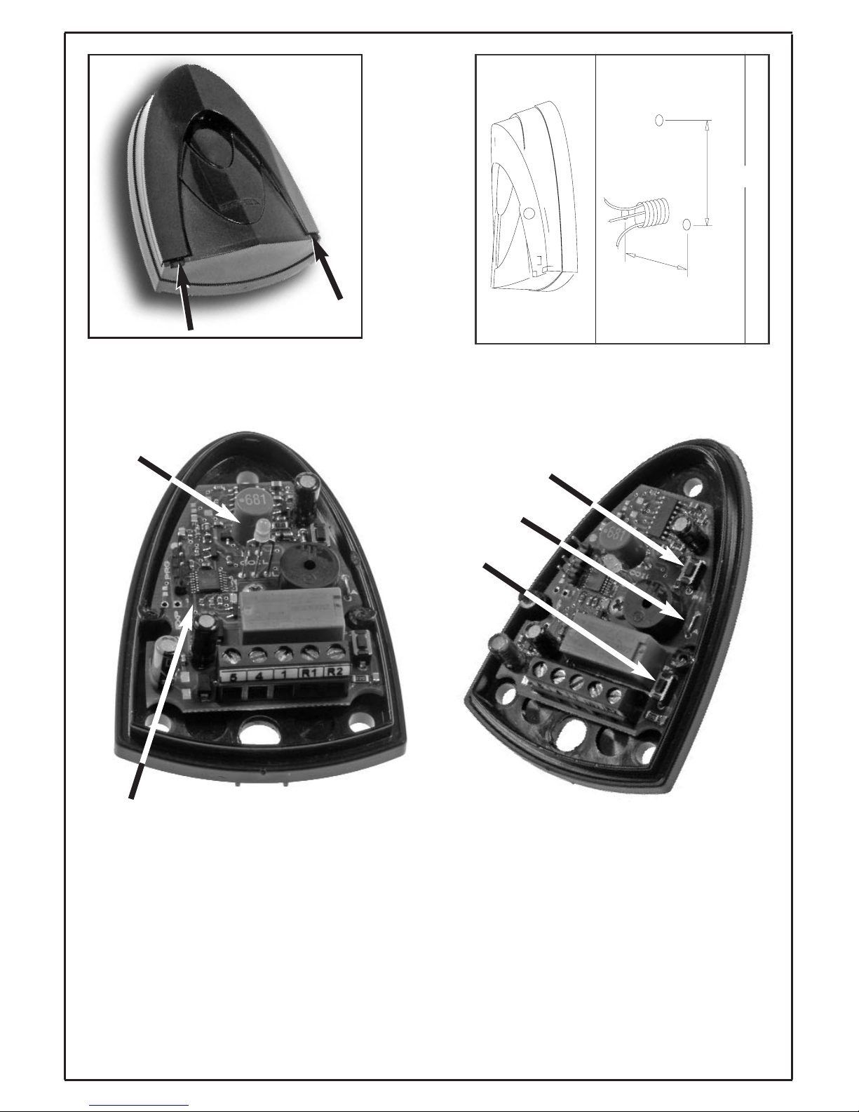
Fig. 1
60
39
60 mm
39 mm
Fig. 2
Fig. 3
LED bicolore
Bicolor LED
LED bicolore
Zweifarbige LED
Led bicolor
LED bicolor
SMD LED
A- ponticello per l’attivazione e disattivazione del
generatore di corrente. Tagliare il ponticello di
metallo per disattivare il generatore di corrente
quando richiesto.
A- jumper for activating/deactivating the current
generator. Cut the metal jumper to deactivating
the current generator when required.
Fig. 4
A- pontet d'activation et désactivation du généra-
teur de courant. Couper le pontet de métal pour
désactiver le générateur de courant si besoin est.
A - Überbrückungsklemme zur Aktivierung bzw.
Deaktivierung des Stromerzeugers. Die
Metallüberbrückung durchschneiden, um im
Bedarfsfall den Stromerzeuger zu deaktivieren.
A - Puente para activar y desactivar el generador
de corriente. Cortar el puente de metal para
desactivar el generador de corriente cuando sea
necesario.
P1
P2
A
A - ponte para activação e desactivação do gera-
dor de corrente. Cortar a ponte de metal para
desactivar o gerador de corrente quando solicitado.
Page 6

6
PROGRAMMAZIONE
Togliere il coperchio di protezione del lettore,
come indicato precedentemente per l’installazione, per eseguire le programmazioni.
La scheda prevede l’utilizzo di due pulsanti P1 e
P2 (come riportato nella serigrafia sul circuito
stampato) per la programmazione delle funzionalità del lettore: di seguito vengono descritte le procedure per effettuare manualmente alcune operazioni di programmazione:
- Memorizzazione chiave transponder in
memoria del lettore.
- Cancellazione chiave transponder dalla
memoria del lettore.
- Cancellazione di tutte le chiavi dalla
memoria del lettore.
- Programmazione tempistiche del relè
interno al lettore.
- Programmazione identificativo del dispositivo lettore.
Per ognuma di tali procedure, dopo una quindicina di secondi se non si effettuano operazioni o
pressioni dei pulsanti P1 e P2 il lettore con un
breve segnale sonoro ritorna nello stato di riposo.
Memorizzazione chiave transponder in memoria del lettore
Premere contemporaneamente i pulsanti P1 e P2,
attendere tre brevi lampeggi sonori del led centrale bicolore e la sua successiva accensione in
verde: con il led verde centrale acceso, tramite il
pulsante P2 scegliere la posizione della chiave in
memoria (ad ogni pressione del pulsante P2 si
incrementa di uno la posizione in memoria su cui
verrà memorizzata la chiave del transponder).
Ad esempio: per memorizzare una chiave transponder nella 2° posizione della memoria del lettore premere il pulsante P2 due volte, in modo
analogo per altre posizioni di memoria.
Subito dopo aver scelto la posizione di memorizzazione avvicinare il transponder per effettuare la
lettura e la successiva memorizzazione (attendere il riconoscimento da parte del lettore con tre
segnalazioni sonore e luminose del led centrale
bicolore ); dopo questa operazione la chiave a
transponder rimane memorizzata e alla successiva lettura (in prossimità del lettore) verrà riconosciuta con la conseguente attivazione del relè se
programmato per l’attivazione.
I
Cancellazione chiave transponder dalla
memoria del lettore
Premere contemporaneamente i pulsanti P1 e
P2, attendere tre brevi lampeggi sonori del led
centrale bicolore e la sua successiva accensione
in verde: con il led verde centrale acceso, premere P1 una volta e dopo un lampeggio sonoro del
centrale bicolore si entra nella modalità di cancellazione chiavi: dopo l’accensione del led SMD
rosso, tramite il pulsante P2 scegliere la posizione della chiave in memoria su cui effettuare la
cancellazione (ad ogni pressione del pulsante P2
si incrementa di uno la posizione in memoria).
Ad esempio: per cancellare una chiave transponder nella 4° posizione della memoria del lettore
premere il pulsante P2 quattro volte, in modo
analogo per altre posizioni di memoria.
Subito dopo aver scelto la posizione di cancellazione mantenere premuto il pulsante P1 fino
all’accensione del led rosso centrale bicolore: il
led centrale bicolore lampeggerà tre volte contemporaneamente all’attivazione del buzzer per
indicare l’avvenuta operazione di cancellazione.
Cancellazione di tutte le chiavi dalla memoria
del lettore
Premere contemporaneamente i pulsanti P1 e P2,
attendere tre brevi lampeggi sonori del led centrale
bicolore e la sua successiva accensione in verde:
con il led verde centrale acceso, premere P1 una
volta e attendere un lampeggio sonoro del led
rosso centrale, premere una seconda volta P1 per
entrare nella modalità di cancellazione totale delle
chiavi memorizzate: attendere l’accensione lampeggiante del led rosso SMD, successivamente
mantenere premuto il pulsante P2 fino all’accensione del led bicolore centrale: il led lampeggerà
tre volte contemporaneamente all’attivazione del
buzzer per indicare l’avvenuta operazione di cancellazione di tutte le chiavi memorizzate nel lettore.
Programmazione tempistiche del relè interno
al lettore
Premere contemporaneamente i pulsanti P1 e P2,
attendere tre brevi lampeggi sonori del led centrale bicolore e la sua successiva accensione in
verde: con il led verde centrale acceso, premere
P1 una volta e attendere un lampeggio sonoro del
led rosso centrale, premere una seconda volta P1
e attendere un secondo lampeggio sonoro del led
rosso centrale, premere una terza volta P1 ed
attendere un terzo lampeggio sonoro del led
rosso centrale per entrare nella modalità di modifica dei tempi di attivazione del relè interno: dopo
l’accensione del led verde centrale e rosso SMD
una prima pressione del pulsante P2 attiva il relè
interno nella modalità bistabile, successive pressioni del pulsante P2 aumentano ad ogni pressione il tempo di attivazione del relè interno di un
secondo (fino ad un massimo di 25 sec.).
I
Page 7

7
Successivamente la pressione del pulsante P1
confermerà l’operazione eseguita:
- con due lampeggi sonori del led centrale bicolore per indicare la modalità bistabile impostata;
- con quattro lampeggi sonori del led centrale
bicolore per indicare la modalità a tempo impostata.
Programmazione identificativo del dispositivo
lettore
Questa fase va eseguita in presenza di impianti
DigiBus nei quali è presente l’interfaccia 6952 e
6952/A con il software di monitoraggio.
Premere contemporaneamente i pulsanti P1 e P2,
attendere tre brevi lampeggi sonori del led centrale bicolore e la sua successiva accensione in
verde: con il led verde centrale acceso, premere
P1 una volta e attendere un lampeggio sonoro del
led rosso centrale, premere una seconda volta P1
e attendere un secondo lampeggio sonoro del led
rosso centrale premere una terza volta P1 ed
attendere un terzo lampeggio sonoro del led rosso
centrale, premere una quarta volta P1 ed attendere l’accensione del led verde centrale e il lampeggio ricorsivo del led rosso SMD per entrare nella
modalità di programmazione dell’identificativo del
lettore a transponder: tramite il pulsante P2 scegliere l’incremento numerico da aggiungere alla
numerazione fissa di base del lettore a 8 cifre (
numerazione fissa di base= 9000).
Ad esempio: per memorizzare l’dentificativo per il
lettore 9002 premere il pulsante P2 due volte.
Successivamente alla pressione del pulsante P1,
il lettore confermerà l’operazione eseguita con 8
lampeggi sonori del led D1 per indicare la memorizzazione dell’identificativo del lettore nella
memoria interna del dispositivo.
Note sulle segnalazioni sonore e visive:
1) L’utilizzo del pulsante P2 per modificare la posizione di programmazione o cancellazione di
una chiave in memoria, per modificare il valore
del tempo di attivazione del relè interno al lettore o infine per modificare il valore dell’identificativo del lettore viene segnalato da un breve
lampeggio del led rosso centrale, tale
lampeggio diventa sonoro al raggiungimento
della decina corrente;
2) nella modalità di attivazione bistabile del relè
interno al lettore lo stato di attivazione della
bobina del relè viene visualizzata dall’accensione contemporanea del led rosso SMD.
I
Page 8
8
Gestione/descrizione dei parametri di 88TK e 800T per gli applicativi software
PC DigiBUS
Analyser 2
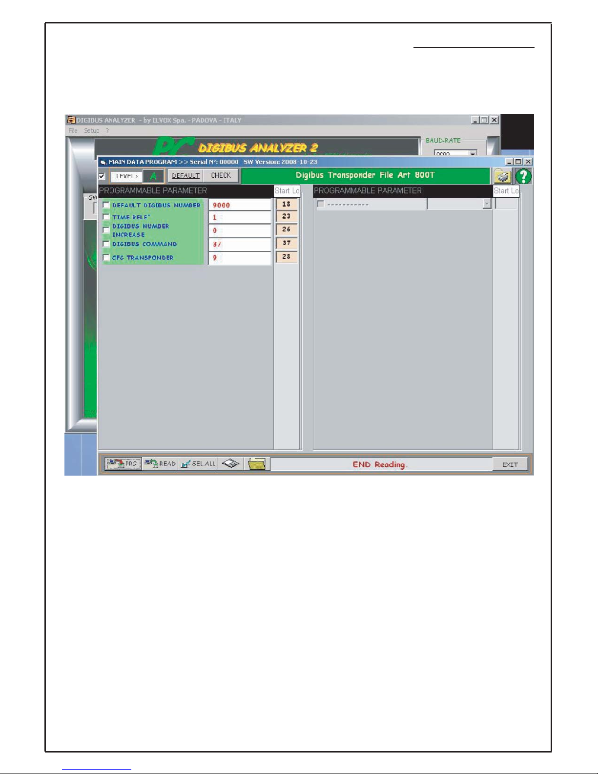
Di seguito vengono descritti i parametri utilizzati dai lettori a transponder ( 88TK e 800T) e modificabili
tramite il tool PC DigiBUS Analyser 2 collegato alla scheda (88TK o 800T) tramite l’interfaccia 6952 o
6952/A:
Descrizione parametri:
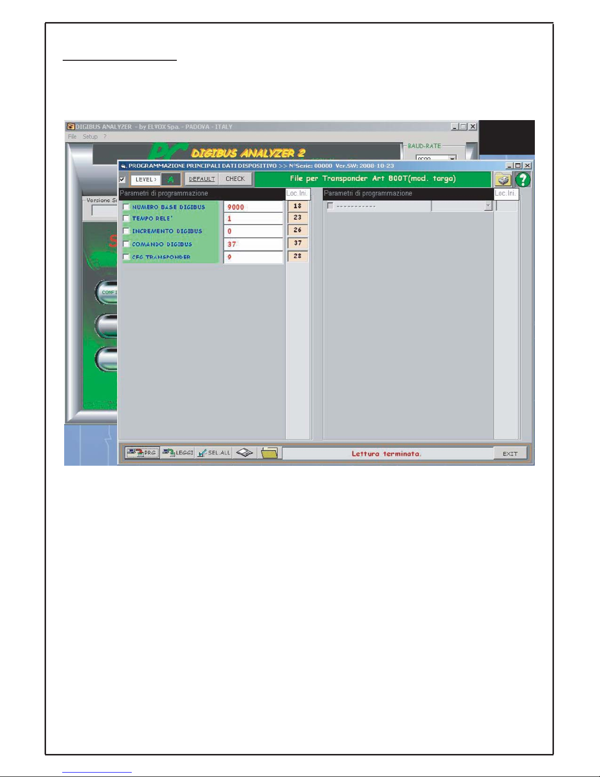
NUMERO BASE DIGIBUS: valore numerico base che identifica una famiglia di lettori a transponder
(del tipo: 88TK o 800T) (valore di fabbrica: 9000);
INCREMENTO DIGIBUS: valore numerico da assegnare al singolo transponder (del tipo: 88TK o
800T) per comporre l’identificativo DigiBUS da associare al dispositivo dove:
identificativo DigiBUS = NUMERO BASE DIGIBUS + INCREMENTO DIGIBUS; (valore di fabbrica: 0);
TEMPO RELE’: tempo di attivazione (espresso in sec ) del relè interno al dispositivo ( 88TK o 800T);
(valore di fabbrica: 1);
COMANDO DIGIBUS: comando DigiBUS da inserire per trasmettere un pacchetto DigiBUS standard
( 88TK o 800T ) ; (valore di fabbrica: 37);
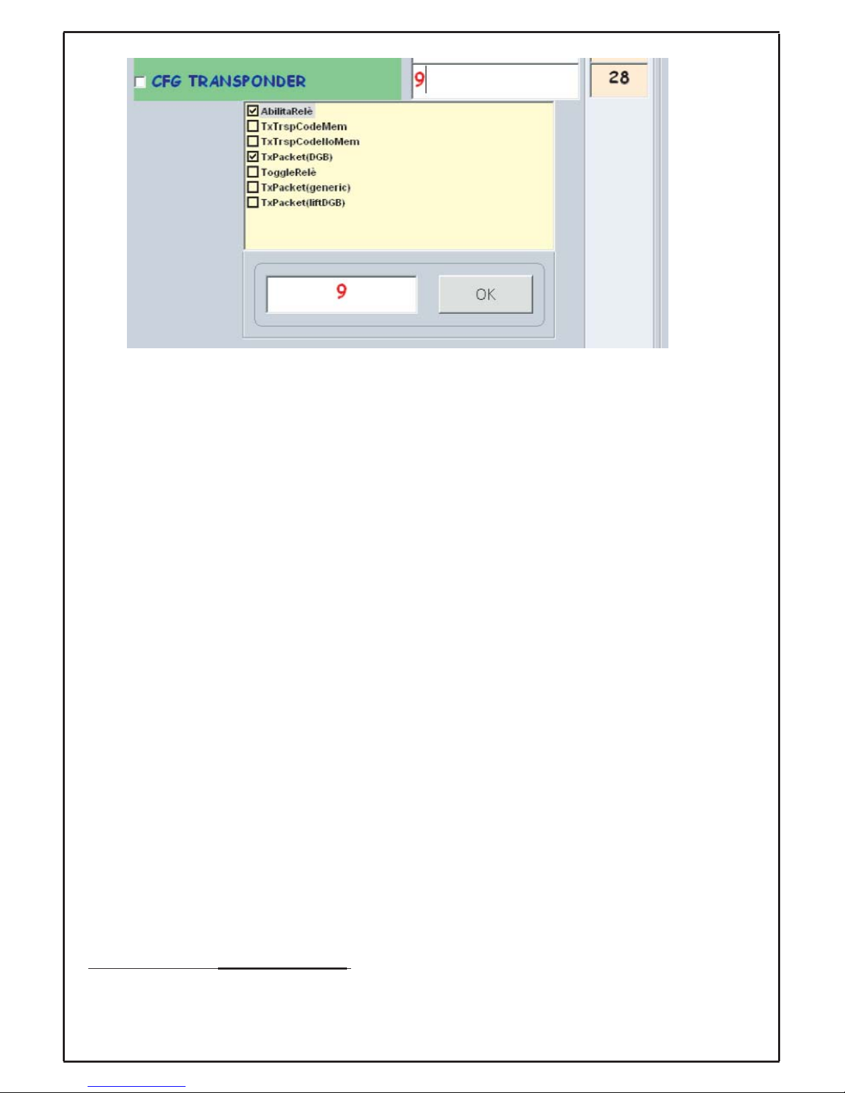
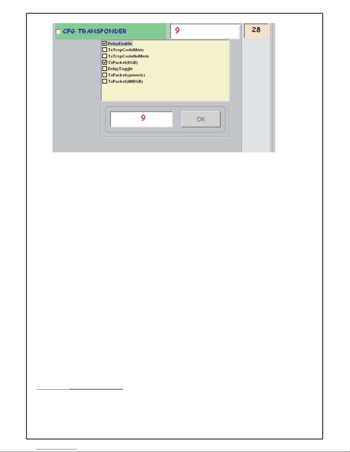
CFG TRANSPONDER: parametro configurabile in modo grafico tramite il tool per modificare o cambiare le tipologie di funzionamento del dispositivo (88TK o 800T), la finestra grafica che appare cliccando sul campo è la seguente (valore di default: 9)
Page 9
9
in questo modo è possibile selezionare una o più funzionalità cliccando con il mouse sulla casella relativa; di seguito si elenca una descrizione delle singole funzioni implementabili tramite una modifica del
parametro CFG TRANSPONDER:
Abilita Relè: se abilitato permette l’attivazione del relè interno al dispositivo altrimenti anche se il lettore riconosce una chiave a transponder tra quelle memorizzate comunque non attiva il suo relè interno;
TxTrspCodeMem: abilita la trasmissione di un pacchetto standard con le informazioni della chiave
letta e riconosciuta tra quelle memorizzate e la relativa posizione della chiave nella memoria del lettore
(88TK o 800T);
(parametro previsto per applicazioni future);
TxTrspCodeNoMem: abilita la trasmissione di un pacchetto standard con le informazioni della chiave
letta anche se non riconosciuta tra quelle memorizzate e la relativa posizione della chiave nella
memoria del lettore (88TK o 800T);
(parametro previsto per applicazioni future);
TxPacket(DGB) : abilita la trasmissione di un pacchetto standard DigiBUS con le seguenti informazioni: l’identificativo del pacchetto di trasmissione = identificativo DigiBUS e il comando DigiBUS trasmesso è quello impostato nel campo COMANDO DIGIBUS
ToggleRelè : se abilitato il parametro Abilita Relè, permette l’attivazione del relè interno al lettore
(88TK o 800T) in modalità bistabile ( TOGGLE): un riconoscimento di una chiave attiva il relè permanentemente un successivo riconoscimento disattiva il relè;
TxPacket (generic): se abilitato il parametro TxPacket(DGB), abilita la trasmissione di un pacchetto
generico non necessariamente DigiBUS ( tale pacchetto viene recuperato da campi interni alla memoria del lettore (88TK o 800T); tale comando ha priorità più alta del parametro
TxPacket (liftDGB);
(parametro previsto per applicazioni future);
TxPacket (liftDGB): se abilitato il parametro TxPacket(DGB), abilita la trasmissione di un pacchetto
standard DigiBUS con le seguenti informazioni: l’identificativo del pacchetto di trasmissione = identificativo DigiBUS + Valore aggiuntivo (valori possibili: 1… 63 )
(applicazione tipica richiesta: invio di un comando ad un ricevitore per l’attivazione di un ascensore al
piano) e il comando DigiBUS trasmesso è quello impostato nel campo COMANDO DIGIBUS; tale
comando ha priorità più bassa del parametro TxPacket
(generic);
Not
a sul parametro TxPacket (liftDGB): Come riportato nella descrizione relativa al parametro, l’utiliz-
zo di tale funzionalità comporta la lettura di un valore aggiuntivo presente nella memoria del lettore
(88TK o 800T ) e modificabile tramite il campo generico Info1 del tool software DataOrganiser;
Page 10
10
Nota:
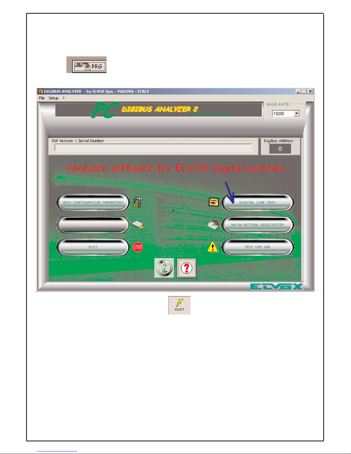
Si ricorda che per rendere effettive ed operative le modifiche ai parametri dell’articolo 800T o 88TK
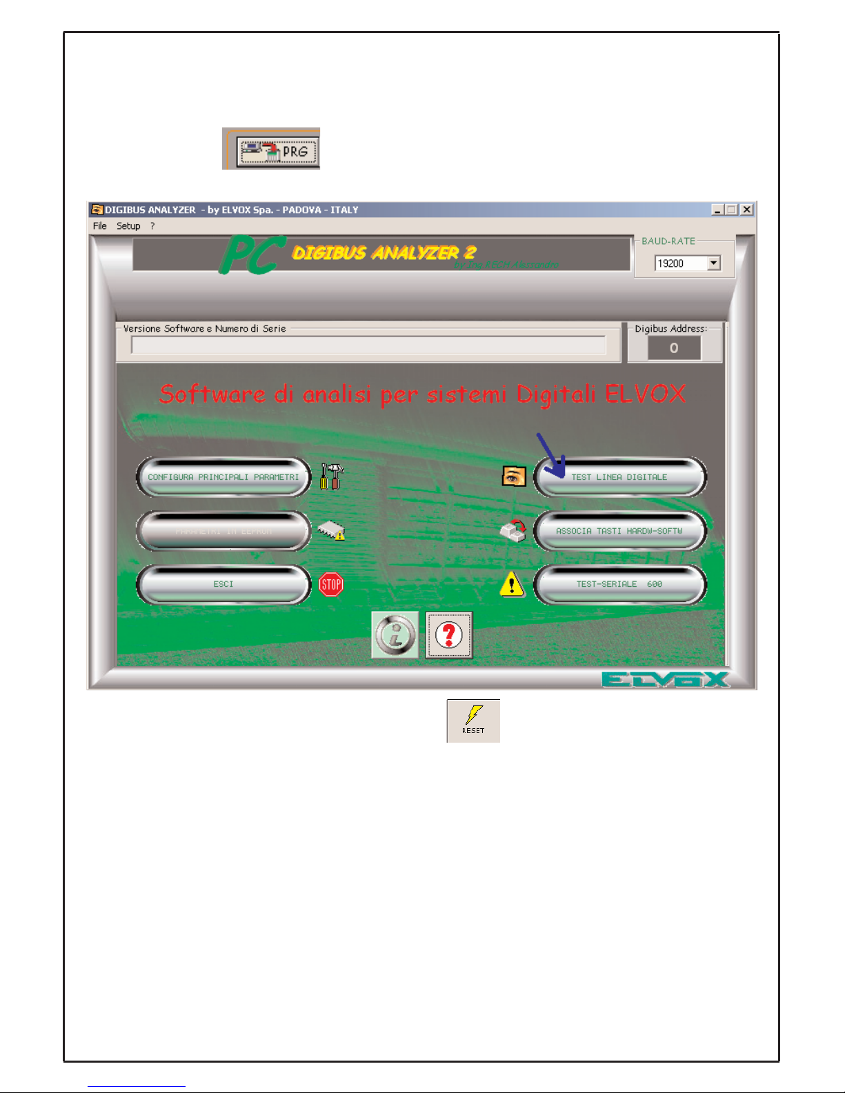
occorre effettuare un RESET del dispositivo; procedere nel seguente modo:
- uscire dalla programmazione parametri dopo averli effettivamente scritti nella memoria del dispositi-
vo tramite il tasto ;
- dalla finestra principale premere il pulsante grafico TEST LINEA DIGITALE:
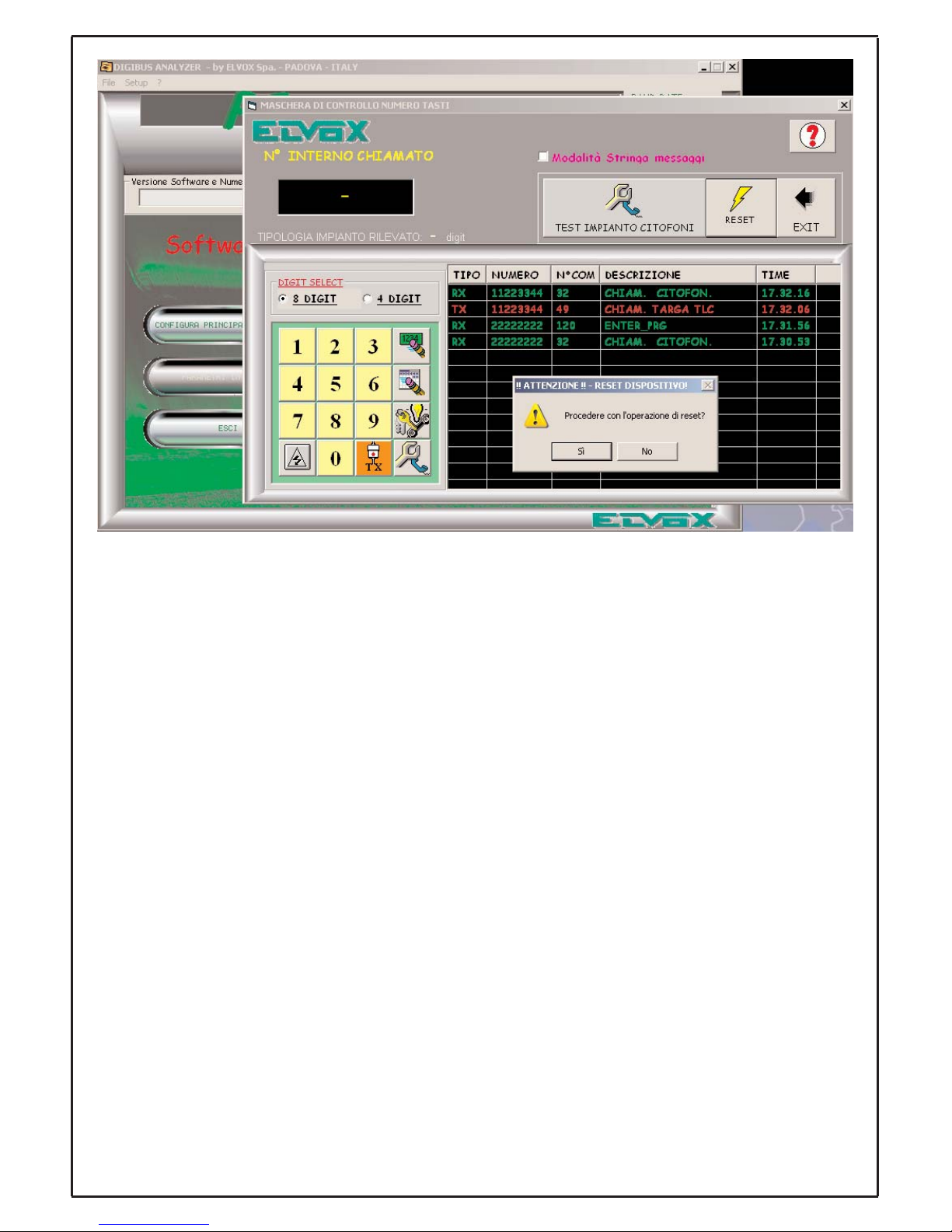
e successivamente premere il pulsante di RESET ( ) dando conferma all’operazione alla
richiesta di procedere con l’operazione:
Page 11
11
L’operazione di reset verrà confermata dal dispositivo con un breve lampeggio del led rosso.
Le modifiche effettuate ai parametri del dispositivo sono ora operative e disponibili.
Page 12
12
Gestione/descrizione dei parametri di 88TK e 800T per gli applicativi software
Dat
aOrganiser
( utilizzo del campo aggiuntivo associato alla chiave transponder da memorizzare )
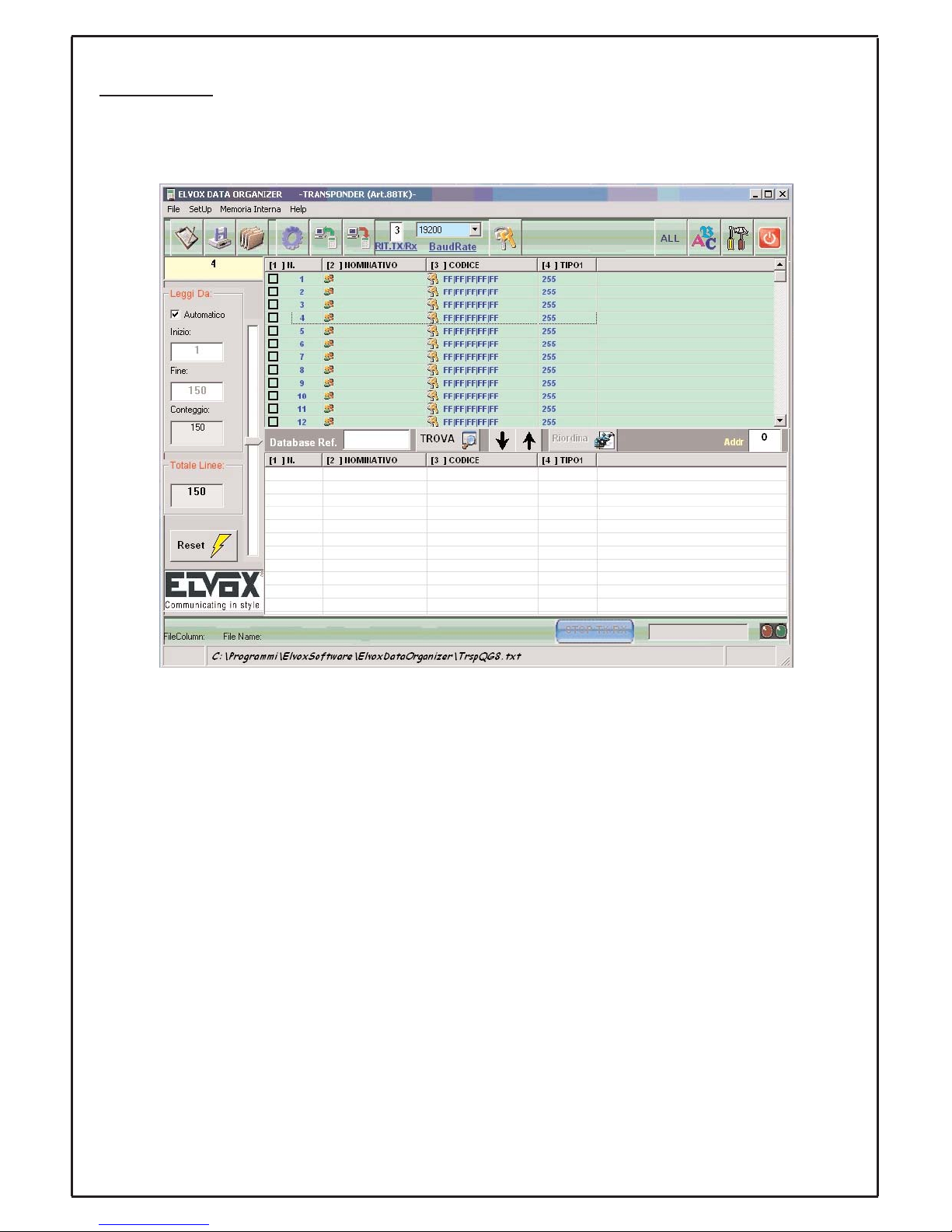
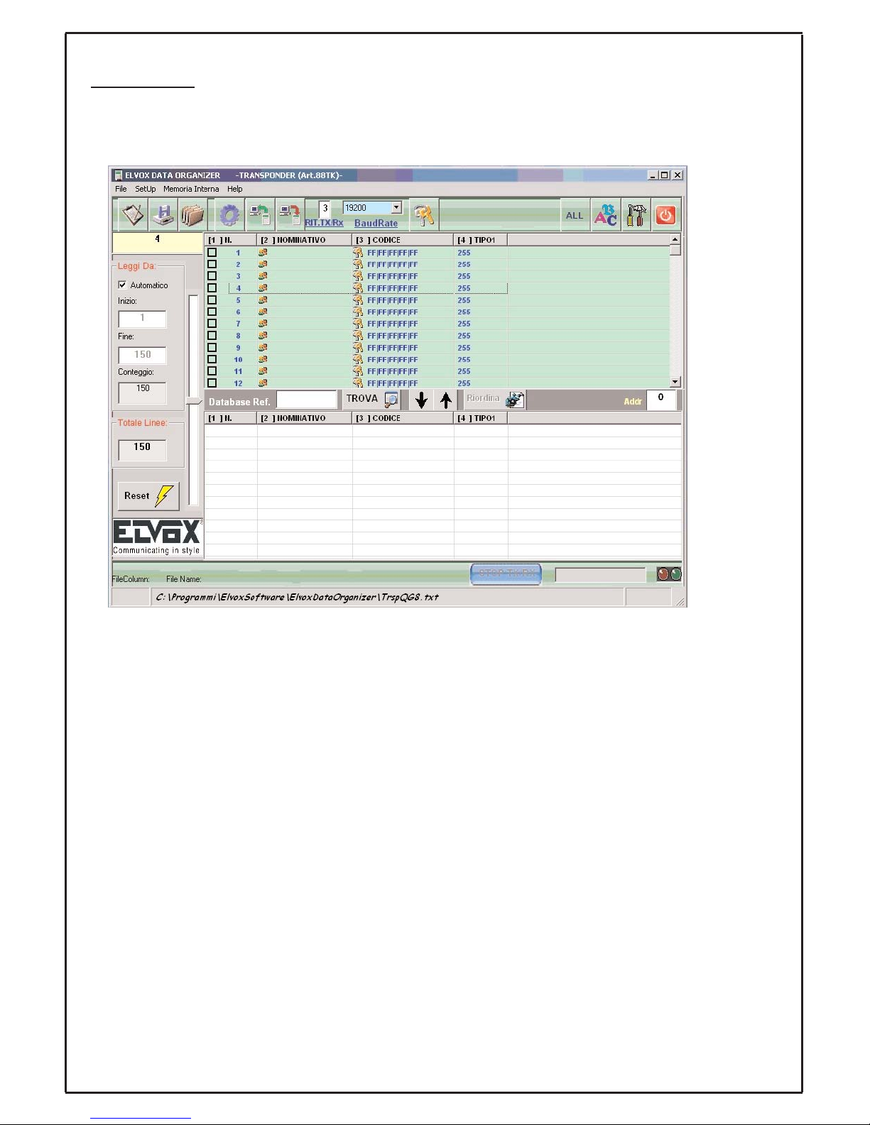
Il DataOrganiser con riferimento all’articolo in esame ( 88TK, 800T ) presenta una schermata del tipo
seguente se il lettore a transponder non ha nessuna chiave memorizzata:
Per l’utilizzo completo delle funzionalità del tool si rimanda al manuale/help in linea , in questa sezione
si descrive l’utilizzo del DataOrganiser in riferimento ad un parametro aggiuntivo presente nel campo
TIPO1 ( cfr. figura sopra ) utilizzato per garantire una funzionalità aggiuntiva: la trasmissione di un pacchetto a standard DigiBUS dove nel campo Identificativo del pacchetto di trasmissione viene riportato
la somma di due valori :
Identificativo del pacchetto = IdentificativoDigiBUS del transponder + valore numerico impostato nel
campo TIPO1 ( vedi IV colonna della figura precedente )
Questo utilizzo serve per applicazioni particolari in cui l’informazione trasmessa viene codificata in
modo da estrarre informazioni per effettuare attuazioni/pilotaggi mirati.
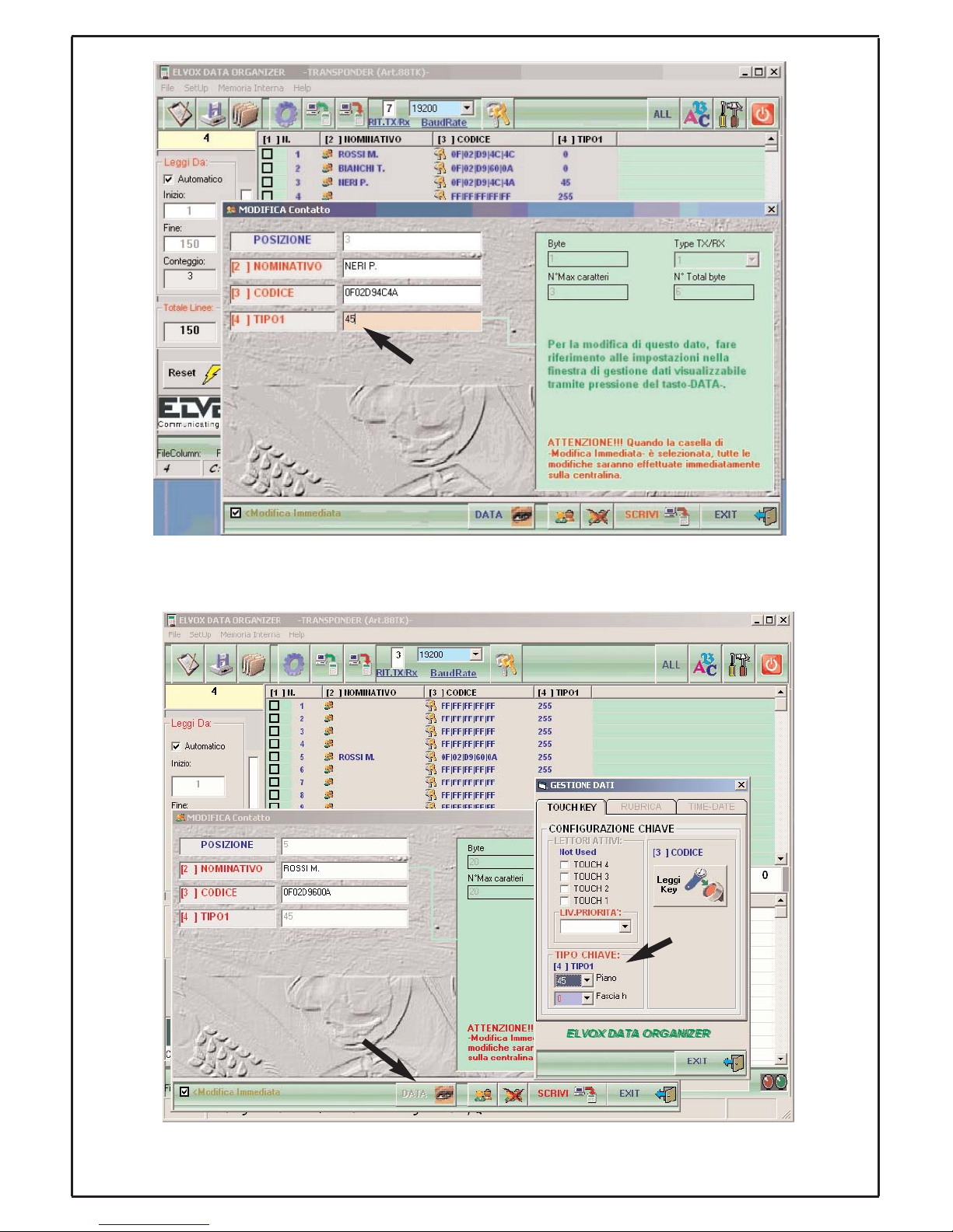
Se abilitati i campi TxPacket (liftDGB) e TxPacket(DGB) relativi al parametro CFG TRANSPONDER
( valori impostati tramite il tool PC DigiBUS Analyser 2 ), i valori scritti ( valori significativi nell’intervallo da 1 a 63 ) nel campo evidenziato in figura vengono sommati all’identificativo DigiBUS e riportati
nell’identificativo trasmesso dal pacchetto a standard DigiBUS con campo impostato dal parametro
COMANDO DIGIBUS ( valore impostato tramite il tool PC DigiBUS Analyser 2 ), vedere la figura
seguente:
Page 13
13
In alternativa alla scrittura direttamente sul campo [4] TIPO1 della finestra MODIFICA Contatto (come
riportato nella figura precedente) è possibile effettuare la stessa modifica dalla finestra che si attiva
premendo il tasto DATA:
dove all’interno del riquadro TIPO CHIAVE si dovrà selezionare il N. del piano mantenendo Fascia h
al valore nullo ( nell’esempio sopra riportato: Piano = 45, Fascia h = 0).
Page 14

14
GB GB
PROGRAMMING
To carry out the programmings remove the reader
protection cover as previously indicated on the
installation instructions.
The board has two push-buttons, P1 and P2,
(as shown in the serigraphy on the printed circuit)
for the programming of the reader functions; the
following are the procedures to make manually a
few programming operations:
- Transponder key storing in reader
memory.
- Transponder key cancellation from the
reader memory.
- Cancellation of all the keys from the reader memory.
- Time programming of internal relay.
- Programming of Id reader device.
For each of such procedures, after about fifteen
seconds, if no operation or pressure of P1 and
P2 push-buttons is carried out, the reader comes
back to stand by position with a short sound
signal.
Transponder key storing in reader memory
Press simultaneously P1 and P2 push-buttons,
wait for three short sound flashings of central
bicolor LED and the switching on of the central
bicolor green LED: with the green LED on, by
means of P2 push-button choose the position of
the key in memory (with each P2 push-button
pressure there is an increase of one position in
memory, where the transponder key will be stored
).
For instance: to memorize a transponder key in
the 2nd position of reader memory press P2 pushbutton twice, in a similar way for other memory
positions.
Just after choosing the storing position move the
transponder closer in order to make the reading
and then the storing process (wait for the recognition by the reader with three acoustic and luminous signals of central bicolor led); after this operation the transponder key is stored and, at the
next reading (near the reader), it will be recognized with the consequent activation of the relay, if
it is set for the activation.
Key transponder cancellation from the reader
memory
Press simultaneously the P1 and P2 buttons, wait
for three short sound flashings of central bicolor
LED and the switching on of the central bicolor
green LED: with the green LED on, press P1
once and, after a sound flashings of the central
bicolor LED, enter the cancellation mode key:
after the red SMD LED switching on, through the
P2 push-button choose in memory the position of
the key where the cancellation has to be carried
out (with each P2 push-button pressure there is
an increase of one position in memory).
For instance: to cancel a transponder key in the
4th position of reader memory press P2 pushbutton four times, in a similar way for other
memory positions.
Just after choosing the cancellation position keep
P1 push-button pressed until the central bicolor
red LED switches on: the central bicolor LED will
flash simultaneously 3 times at the activation of
buzzer to indicate the cancellation.
Cancellation of all the keys from the reader
memory
Press simultaneously the P1 and P2 buttons, wait
for three short sound flashings of central bicolor
LED and the switching on of central bicolor green
LED: with the green LED on, press P1 once and
wait for a sound flashing of the central bicolor
LED, press for a second time P1 to enter the
mode of total cancellation of the stored keys: wait
for the flashing switching on of the red SMD LED ,
keep P2 push-button pressed until the central
bicolor LED switches on: the LED will flash simultaneously 3 times at the activation of buzzer to
show the cancellation of all the keys stored in the
reader.
Time programming of internal relay
Press simultaneously the P1 and P2 buttons, wait
for three short sounds flashings of central bicolor
LED and the switching on of central bicolor green
LED: with the green LED on, press P1 once and
wait for a sound flashing of the central bicolor
LED, press for a second time P1 and wait for a
sound flashings of the central bicolor LED, press
for a third time P1 and wait for a sound flashings
of the central bicolor LED to enter the mode of
time programming of internal relay: after the switching on of the green bicolor LED and red SMD
LED, a first pressure of P2 push-button sets up
the internal relay in the bistable mode, further P2
push-button pressures increase of one second for
each pressure the start time of the internal relay
(up to a maximum of 25 sec).
Page 15

15
GB
Then, the P1 push-button pressure will confirm
the performed operation:
- with two sound flashings of the central bicolor
LED to indicate that the bistable mode is set up;
- with four sound flashing of the central bicolor
LED to indicate the time mode is set up;
Programming of Id reader device
This phase is to be carried out on DIGIBUS installations using the interface type 6952 and 6952/A
with the monitoring software.
Press simultaneously the P1 and P2 buttons, wait
for three short sounds flashings of central bicolor
LED and the switching on of central bicolor green
LED: with the green LED on, press P1 once and
wait for a sound flashings of the central bicolor
LED, press for a second time P1 and wait for a
sound flashings of the central bicolor LED, press
for a third time P1 and wait for a sound flashings
of the central bicolor LED, press a fourth time P1
and wait for the switching on of green bicolor
LED and the flashing of the red SMD LED to enter
the programming mode of Id reader device: by
means of P2 push-button choose the numeric
increase to be added to the basic fixed numeration of the 8 digit reader (basic fixed numeration =
9000).
For instance: to memorize Id for the 9002 reader
press the P2 push- button twice.
After P1 push-button pressure, the reader will
confirm the operation with 8 sound flashings of
bicolor central LED to show the storing of Id reader in the internal memory of the device.
Notes on the sound and visual signals:
1) the use of P2 push- button to modify the position of programming or cancellation of a key in
memory, to modify the value of the start time
of internal relay of the reader or to modify
the id reader value is indicated by a short
red flashing of the central bicolor LED. After
ten flashings there is an acoustic signal.
2) in bistable activation mode of the internal
relay the state of activation of the relay coil is
shown by the simultaneous switching on of
the red SMD LED;
Page 16
16
Management/description of the 88TK and 800T parameters for the PC DigiBUS Analyser 2
software applications
Here we describe the parameters used by the transponder readers (88TK and 800T) that can be
modified with the PC DigiBUS Analyser 2 tool connected to the card (88TK or 800T) via the interface
6952 or 6952/A:
Description of parameters:
DIGIBUS STANDARD NUMBER: standard numerical value identifying a family of transponder readers
(type: 88TK or 800T) (default value: 9000);
DIGIBUS INCREMENT: numerical value to assign to the single transponder (type: 88TK or 800T) to
form the DigiBUS identifier to be associated with the device, where: DigiBUS identifier = DIGIBUS
STANDARD NUMBER + DIGIBUS INCREMENT; (default value: 0);
RELAY TIME: activation time (expressed in sec.) of the relay inside the device (88TK or 800T);
(default value: 1);
DIGIBUS COMMAND: DigiBUS command to enter to transmit a standard DigiBUS packet (88TK or
800T); (default value: 37);
CFG TRANSPONDER: parameter can be configured graphically with the tool to edit or change the
types of operation of the device (88TK or 800T), clicking on the field shows the following graphical window (default value: 9):
Page 17
17
in this way it is possible to select one or more functions by clicking with the mouse on the relevant box;
here we list a description of the single functions that can be implemented by modifying the CFG TRANSPONDER parameter:
Enable Relay: when enabled it permits activating the relay inside the device, otherwise even if the
reader acknowledges a transponder key from among the ones stored in memory it will not activate its
internal relay;
TxTrspCodeMem: enables the transmission of a standard packet with the data of the key read and
acknowledged from among the ones stored in memory and the associated position of the key in the
reader memory (88TK or 800T); (parameter planned for future applications);
TxTrspCodeNoMem: enables the transmission of a standard packet with the data of the key read
although not acknowledged from among the ones stored in memory and the associated position of the
key in the reader memory (88TK or 800T); (parameter planned for future applications);
TxPacket(DGB) : enables the transmission of a DigiBUS standard packet with the following data: transmission packet identifier = DigiBUS identifier and the DigiBUS command transmitted is the one set in
the DIGIBUS COMMAND field
ToggleRelè: when the Enable Relay parameter is enabled it permits activating the relay inside the
reader (88TK or 800T) in bistable mode (TOGGLE): acknowledgment of a key activates the relay permanently, another acknowledgment deactivates the relay;
TxPacket (generic): when the TxPacket(DGB) parameter is enabled it permits the transmission of a
general packet, not necessarily DigiBUS (this packet is retrieved from fields in the reader memory
(88TK or 800T); this command takes a higher priority than the TxPacket (liftDGB) parameter; (parameter planned for future applications);
TxPacket (liftDGB): when the TxPacket(DGB) parameter is enabled it permits the transmission of a
DigiBUS standard packet with the following data: transmission packet identifier = DigiBUS identifier +
Additional value (possible values: 1… 63 )
(typical application required: send a command to a receiver to activate a lift at the floor) and the transmitted DigiBUS command is the one set in the DIGIBUS COMMAND field; this command takes a
lower priority than the TxPacket (generic) parameter;
Note on the
TxPacket (liftDGB) parameter: As stated in the description of the parameter, using this
function requires reading an additional value in the reader memory (88TK or 800T) that can be modified via the generic field Info1 of the DataOrganiser software tool;
Page 18
18
Note:
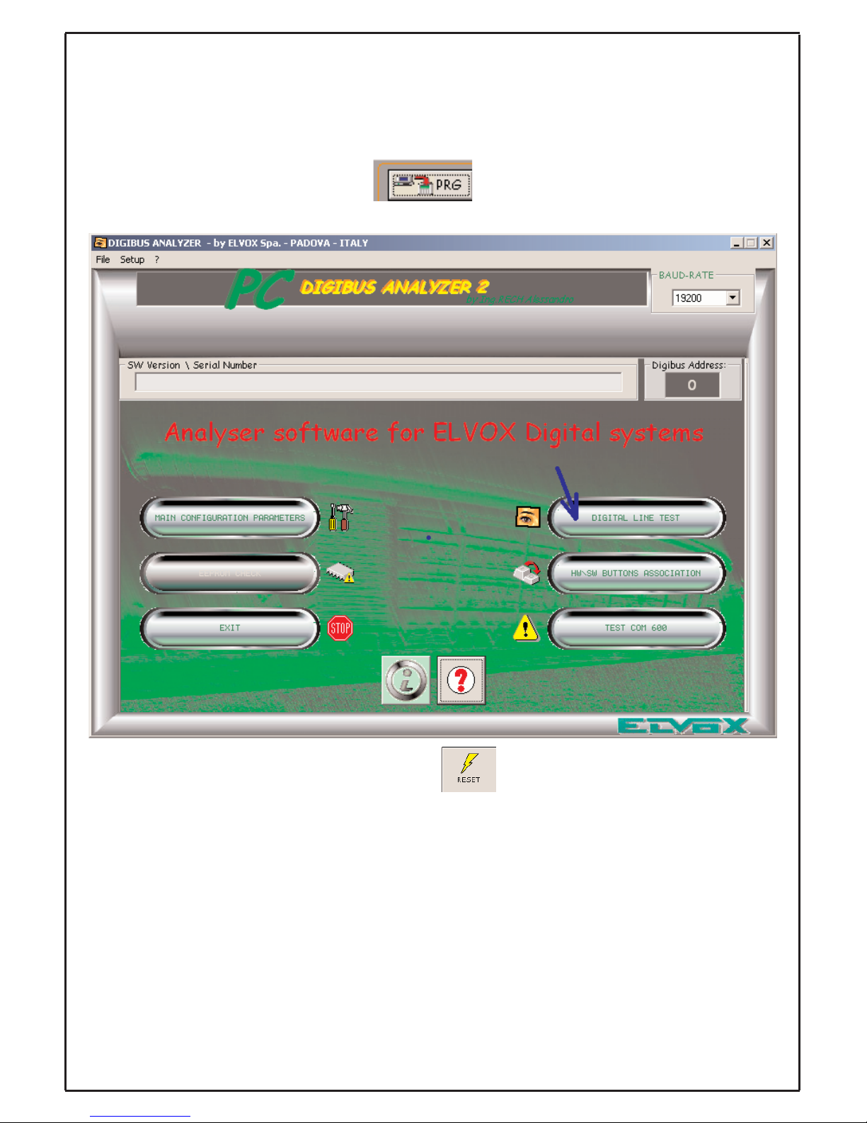
Remember that to make the changes to the parameters of article 800T or 88TK effective
and operative, it is necessary to RESET the device; proceed as follows:
- exit parameter programming after actually writing them to the device's memory by using
button ;
- in the main window, press the DIGITAL LINE TEST graphic button:
and afterwards press the RESET button ( ) confirming the operation when requested to proceed with the operation:
Page 19

19
The reset will be confirmed by the device with a brief blink of the red LED.
The changes made to the parameters of the device are now operative and available.
Page 20

20
Management/description of the 88TK and 800T parameters for the DataOrganiser software
applications (using the additional field associated with the transponder key to save to memory)
DataOrganiser, referring to the article at issue (88TK, 800T), presents the following type of screen if
the transponder reader has no key stored in memory:
For full use of the tool functions, please refer to the manual/on-line help. This section describes the
use of DataOrganiser with one additional parameter in the field TYPE1 (TIPO1) (cfr. figure above)
used to provide an additional function: the transmission of a DigiBUS standard packet in which the
transmission packet identifier field gives the sum of two values: Packet identifier = Transponder
DigiBUS identifier + numerical value set in field TYPE1 (TIPO1) (see column IV in the figure above)
This use is for special applications in which the transmitted information is coded so as to extract information for targeted executions/piloting.
If the TxPacket (liftDGB) and TxPacket (DGB) fields are enabled for the CFG TRANSPONDER parameter (values set with the PC DigiBUS Analyser 2 tool), the written values (significant values in the
range from 1 to 63) in the field shown in the figure are added to the DigiBUS identifier and given in the
identifier transmitted by the DigiBUS standard packet with the field set by the DIGIBUS COMMAND
parameter (value set with the PC DigiBUS Analyser 2 tool), see the following figure::
Page 21

21
Alternatively to writing directly in field [4] TYPE1 (TIPO1) of the EDIT Contact window (as shown in
the preceding figure), it is possible to make the same change via the window activated by pressing the
DATA button:
where in the KEY TYPE box you need to select the No. of the floor keeping Band h null (in the above
example: Floor = 45, Band h = 0).
Page 22

22
PROGRAMMATION
Retirer le couvercle de protection du lecteur,
comme indiqué précédemment pour l’installation,
pour effectuer les programmations.
La carte prévoit l'utilisation de 2 boutons P1 et P2
(comme indiqué sur la sérigraphie du circuit
imprimé) pour la programmation des fonctions du
lecteur : vous trouverez ci-dessous les procédures
manuelles de certaines opérations de programmation :
- Mémorisation de la clé transpondeur dans
la mémoire du lecteur.
- Effacement de la clé transpondeur de la
mémoire du lecteur.
- Effacement de toutes les clés de la mémoire du lecteur.
- Programmation des délais du relais interne
du lecteur.
- Programmation identification du dispositif
du lecteur.
Pour chaque procédure, après 15 secondes sans
opération ou pression des boutons P1 et P2 le
lecteur par un court signal sonore revient à l'état
de repos.
Mémorisation de la clé transpondeur dans la
mémoire du lecteur
Appuyer simultanément les boutons P1 et P2,
attendre 3 clignotements brefs sonores de la led
centrale bicolore et son allumage vert : avec la led
verte centrale allumée, appuyer le bouton P2 pour
choisir la position de la clé en mémoire (chaque
pression du bouton P2 incrémente de 1 la position
en mémoire sur laquelle sera mémorisée la clé du
transpondeur).
Par exemple: pour mémoriser une clé transpondeur sur la 2° position de la mémoire du lecteur
appuyer le bouton P2 deux fois, de façon identique aux autres positions en mémoire.
Après avoir choisi la position de mémorisation
approcher le transpondeur pour effectuer la lecture et la mémorisation (attendre la reconnaissance
par le lecteur avec 3 signalisations sonores lumineuses de la led centrale bicolore ) ; après quoi la
clé à transpondeur reste mémorisée, et à la prochaine lecture (à proximité du lecteur) elle sera
reconnue avec activation du relais si programmé
pour l'activation.
F
Effacement de la clé à transpondeur de la
mémoire du lecteur
Appuyer simultanément les boutons P1 et P2,
attendre 3 clignotements brefs sonores de la led
centrale bicolore et son allumage vert : avec la led
verte centrale allumée, appuyer P1 une fois et
après un clignotement sonore de la centrale bicolore on entre en modalité d'effacement des clés :
après allumage de la led SMD rouge, avec le bouton P2 choisir la position de la clé en mémoire sur
laquelle effectuer l'effacement (à chaque pression
du bouton P2 on incrémente de 1 la position en
mémoire).
Par exemple: pour effacer une clé transpondeur
en 4° position de la mémoire du lecteur appuyer
le bouton P2 quatre fois, de façon analogue pour
les autres positions en mémoire.
Après avoir choisi la position d'effacement maintenir appuyé le bouton P1 jusqu'à allumage de la
led rouge centrale bicolore : la led centrale bicolore clignotera 3 fois simultanément lors de l'activation du ronfleur pour confirmer l'opération d'effacement.
Effacement de toutes les clés de la mémoire
du lecteur
Appuyer simultanément les boutons P1 et P2,
attendre 3 clignotements brefs sonores de la led
centrale bicolore et son allumage vert : avec la led
verte centrale allumée, appuyer P1 une fois et
après un clignotement sonore de la led rouge centrale, appuyer une seconde fois P1 pour entrer en
modalité d'effacement totale des clés mémorisées :
après allumage clignotant de la led SMD rouge,
maintenir appuyé le bouton P2 jusqu'à allumage
de la led bicolore centrale : la led clignotera 3 fois
simultanément à l'activation du ronfleur pour indiquer l'effacement de toutes les clés mémorisées
dans le lecteur.
Programmation délais du relais interne au lecteur
Appuyer simultanément les boutons P1 et P2,
attendre 3 clignotements brefs sonores de la led
centrale bicolore et son allumage vert : avec la led
verte centrale allumée, appuyer P1 une fois et
après un clignotement sonore de la led rouge centrale, appuyer une seconde fois P1 et attendre un
second clignotement sonore de la led rouge centrale, appuyer une troisième fois P1 et attendre un
troisième clignotement sonore de la led rouge
centrale pour entrer en modalité de modification
des effacements de la clé à transpondeur de la
mémoire du lecteur.
F
Page 23

23
Programmation délais du relais interne au lecteur
Appuyer simultanément les boutons P1 et P2,
attendre 3 clignotements brefs sonores de la led
centrale bicolore et son allumage vert : avec la led
verte centrale allumée, appuyer P1 une fois et
après un clignotement sonore de la led rouge centrale, appuyer une seconde fois P1 et attendre un
second clignotement sonore de la led rouge centrale, appuyer une troisième fois P1 et attendre un
troisième clignotement sonore de la led rouge
centrale pour entrer en modalité de modification
des temps d'activation du relais interne : après l'allumage des leds verte centrale et rouge SMD une
première pression du bouton P2 active le relais
interne en modalité bistable, une autre pression
du bouton P2 augmente à chaque pression le
temps d'activation du relais interne d'une seconde
(jusqu'à un maximum de 25 secondes). Une autre
pression du bouton P1 confirmera l'opération :
- deux clignotements sonores de la led centrale
bicolore pour indiquer la modalité bistable programmée;
- quatre clignotements sonores de la led centrale
bicolore pour indiquer la modalité temporisée;
Programmation d'identification du dispositif
lecteur
Cette phase doit être effectuée en présence d'installations DigiBus sur lesquelles se trouve l’interface 6952 et 6952/A avec le logiciel de pilotage.
Appuyer simultanément les boutons P1 et P2,
attendre 3 clignotements brefs sonores de la led
centrale bicolore et son allumage vert: avec la led
verte centrale allumée, appuyer P1 une fois et
après un clignotement sonore de la led rouge centrale, appuyer une seconde fois P1 et attendre un
second clignotement sonore de la led rouge centrale, appuyer une troisième fois P1 et attendre un
troisième clignotement sonore de la led rouge
centrale, appuyer une quatrième fois P1 et attendre l'allumage de la led verte centrale et le clignotement récursif de la led rouge SMD pour entrer
en modalité de programmation de l'identification
du lecteur à transpondeur : via le bouton P2 choisir l'incrémentation numérique à ajouter à la
numérotation fixe de base du lecteur à 8 chiffres (
numérotation fixe de base= 9000).
Par exemple pour mémoriser l’identification pour
le lecteur 9002 appuyer le bouton P2 deux fois.
F
Suite à la pression du bouton P1, le lecteur confirmera l'opération effectuée par 8 clignotement
sonores de la led D1 pour indiquer la mémorisation de l'identification du lecteur dans la mémoire
interne du dispositif.
Notes sur les signalisations sonores et
visuelles :
1)
l’utilisation du bouton P2 pour modifier la position de programmation ou effacement d'une
clé en mémoire, pour modifier la valeur du
temps d'activation du relais interne au lecteur
ou enfin pour modifier la valeur de l’identification du lecteur, est signalée par un court clignotement de la led rouge centrale, ce clignotement devient sonore lors de l'atteinte de la
dizaine courante;
2) en modalité d'activation bistable du relais
interne au lecteur l'état d'activation de la bobine du relais est visualisé par l'allumage simultané de la led rouge SMD.
F
Page 24

24
Gestion/description des paramètres de 88TK et 800T pour les systèmes d'exploitation logiciel
PC
DigiBUS Analyser 2
Ci-après, la description des paramètres utilisés par les lecteurs à transponder (88TK et 800T) et modifiables au moyen de l'outil PC DigiBUS Analyser 2 relié à la carte (88TK ou 800T) au moyen de l'interface 6952 ou 6952/A :
Description paramètres :
NUMÉRO BASE DIGIBUS : valeur numérique de base qui identifie une famille de lecteurs à transpon-
der (du type : 88TK ou 800T) (valeur d'usine : 9000) ;
AUGMENTATION DIGIBUS : valeur numérique à attribuer au transponder (du type : 88TK ou 800T)
pour composer le numéro d'identification DigiBUS à associer au dispositif avec : numéro d'identification DigiBUS = NUMÉRO BASE DIGIBUS + AUGMENTATION DIGIBUS ; (valeur d'usine : 0) ;
TEMPS RELAIS : temps d'activation (exprimé en sec) du relais interne du dispositif (88TK ou 800T) ;
(valeur d'usine : 1) ;
COMMANDE DIGIBUS : commande DigiBUS à insérer pour transmettre un paquet DigiBUS standard
( 88TK ou 800T ) ; (valeur d'usine : 37);
CFG TRANSPONDER : paramètre programmable de manière graphique au moyen de l'outil pour
modifier ou changer les typologies de fonctionnement du dispositif (88TK ou 800T); la fenêtre graphique qui apparaît en cliquant le champ est la suivante (default valeur : 9):
Page 25

25
de cette manière, il est possible de sélectionner une ou plusieurs fonctionnalités en cliquant avec la
souris la case correspondante ; ci-dessous, la description des différentes fonctions pouvant être introduites au moyen de la modification du paramètre CFG TRANSPONDER :
Validation relais : si validé, il permet d'activer le relais interne du dispositif sinon, même si le lecteur
reconnaît une clé à transponder parmi celles mémorisées, il n'active pas son relais interne ;
TxTrspCodeMem : valide la transmission d'un paquet standard avec les informations de la clé lue et
reconnue parmi celles mémorisées et la position correspondante de la clé dans la mémoire du lecteur
(88TK ou 800T) ; (paramètre prévu pour applications futures) ;
TxTrspCodeNoMem : valide la transmission d'un paquet standard avec les informations de la clé lue
même si non reconnue parmi celles mémorisées et la position correspondante de la clé dans la
mémoire du lecteur (88TK ou 800T) ; (paramètre prévu pour applications futures) ;
TxPacket(DGB) : valide la transmission d'un paquet standard DigiBus avec les informations suivantes
: numéro d'identification du paquet de transmission = numéro d'identification DigiBUS et la commande
DigiBUS transmise est celle introduite dans le champ COMMANDE DIGIBUS ;
ToggleRelais : si le paramètre Validation relais est validé, il permet d'activer le relais interne du lecteur ( 88TK ou 800T ) en modalité bistable (TOGGLE) : une reconnaissance d'une clé active le relais
de manière permanente ; une nouvelle reconnaissance désactive le relais ;
TxPacket (generic) : si le paramètre TxPacket(DGB) est validé, il valide la transmission d'un paquet
générique non nécessairement DigiBUS (ce paquet est récupéré dans des champs internes à la
mémoire du lecteur 88TK ou 800T) ; cette commande a une priorité plus haute que le paramètre
TxPacket (liftDGB) ; (paramètre prévu pour applications futures) ;
TxPacket (liftDGB) : si le paramètre TxPacket(DGB) est validé, il valide la transmission d'un paquet
standard DigiBUS avec les informations suivantes : le numéro d'identification du paquet de transmission = numéro d'identification DigiBUS + valeur supplémentaire (valeurs possibles : 1… 63 ) (application typique demandée : envoi d'une commande à un récepteur pour l'activation d'un ascenseur à l'étage) et la commande DigiBUS transmise est celle introduite dans le champ COMMANDE DIGIBUS ;
cette commande a une priorité plus basse que le paramètre TxPacket (generic) ;
Remarque
sur le paramètre TxPacket (liftDGB) : comme indiqué dans la description relative au
paramètre, l'emploi de cette fonctionnalité comporte la lecture d'une valeur supplémentaire présente
dans la mémoire du lecteur (88TK ou 800T) et modifiable au moyen du champ générique Info1 de l'outil logiciel DataOrganiser ;
Page 26
26
Remarque :
Nous rappelons que, pour que les modifications aux paramètres de l'article 800T ou 88TK
soient effectives et opérationnelles, il est nécessaire d'effectuer un RESET du dispositif ;
procéder de la manière suivante :
- quitter la programmation paramètres après les avoir effectivement écrits dans la mémoire
du dispositif au moyen de la touche ;
- depuis la fenêtre principale, appuyer sur le bouton graphique TEST LIGNE NUMÉRIQUE
ensuite, appuyer sur le bouton de RESET ( ) en confirmant à l'apparition de la
demande de procéder à l'opération :
Page 27

27
L'opération de reset sera confirmée par le dispositif par un clignotement bref de la led
rouge.
Les modifications effectuées aux paramètres du dispositif sont maintenant opérationnelles
et disponibles.
Page 28
28
Gestion/description des paramètres de 88TK et 800T pour les systèmes d'exploitation logiciel
Dat
aOrganiser
(utilisation du champ supplémentaire associé à la clé transponder à mémoriser )
Le DataOrganiser, avec référence à l'article examiné (88TK, 800T), présente une page-écran du type
suivant si le lecteur à transponder n'a aucune clé mémorisée :
Pour l'utilisation complète des fonctionnalités de l'outil, voir le manuel/aide en ligne ; cette section
décrit l'utilisation du DataOrganiser en référence à un paramètre supplémentaire présent dans le
champ TYPE 1 (voir figure ci-dessus) utilisé pour garantir une fonctionnalité supplémentaire : la transmission d'un paquet à standard DigiBUS dans lequel, dans le champ numéro d'identification du
paquet de transmission, se trouve la somme de deux valeurs : numéro d'identification du paquet =
numéro d'identification DigiBUS du transponder + valeur numérique introduite dans le champ TYPE 1
(voir IV colonne de la figure précédente) Cette utilisation sert pour des applications particulières dans
lesquelles l'information transmise est codée de manière à extraire des informations pour effectuer des
applications/pilotages précis.
Si les champs TxPacket (liftDGB) et TxPacket(DGB) relatifs au paramètre CFG TRANSPONDER
sont validés (valeurs introduites avec l'outil PC DigiBUS Analyser 2 ), les valeurs écrites (valeurs
significatives dans l'intervalle de 1 à 63) dans le champ mis en évidence sur la figure sont additionnées au numéro d'identification DigiBUS et rapportées dans le numéro d'identification transmis par
le paquet à standard DigiBUS avec champ introduit par le paramètre COMMANDE DIGIBUS (valeur
introduite avec l'outil PC DigiBUS Analyser 2 ), voir la figure suivante :
Page 29

29
en alternative à l'écriture directement dans le champ [4] TYPE 1 de la fenêtre MODIFICATION Contact
(comme indiqué dans la figure précédente), il est possible d'effectuer la même modification depuis la
fenêtre qui s'ouvre en appuyant sur la touche DATA :
où, l'intérieur du carré TYPE CLE, il faudra sélectionner le numéro de l'étage en maintenant Tranche h
à la valeur nulle (dans l'exemple ci-dessus : Étage = 45, Tranche h = 0).
Page 30

Löschen des Transponderschlüssels aus dem
Leserspeicher
Tasten P1 und P2 gleichzeitig drücken, drei kurze
Ton- und Blinksignale der zweifarbigen zentralen
Led und deren Umschalten auf grünes Dauerlicht
abwarten: dann P1 einmal drücken, nach einem
Ton- und Blinksignal der zweifarbigen zentralen
Led wird der Modus Schlüssellöschung abgerufen: nach Einschalten der roten Led SMD über
die Taste P2 den Speicherplatz wählen, in dem
die Löschung erfolgen soll ( jedes Drücken von
Taste P2 inkrementiert den Speicherplatz um
eins).
Beispiel: zum Löschen eines
Transponderschlüssels im 4. Speicherplatz des
Lesers Taste P2 vier Mal drücken, dementsprechend für alle anderen Speicherplätze vorgehen.
Unmittelbar nach Wahl des Speicherplatzes, in
dem die Löschung erfolgen soll, Taste P1 bis zum
Aufleuchten des roten Lichts der zweifarbigen
zentralen Led gedrückt halten: während die zweifarbige zentrale Led drei Mal blinkt, aktiviert sich
gleichzeitig der Summer. Beide Signale zeigen
an, dass die Löschung erfolgt ist.
Löschen sämtlicher Schlüssel aus dem
Leserspeicher
Tasten P1 und P2 gleichzeitig drücken, drei kurze
Ton- und Blinksignale der zweifarbigen zentralen
Led und deren Umschalten auf grünes Dauerlicht
abwarten: dann P1 einmal drücken und ein Tonund Blinksignal der roten zentralen Led abwarten,
P1 noch einmal drücken, um den Modus Totale
Löschung der gespeicherten Schlüssel abzurufen: warten, bis die rote Led SMD blinkt, danach
Taste P2 bis zum Aufleuchten der zweifarbigen
zentralen Led gedrückt halten: während die Led
drei Mal blinkt, aktiviert sich gleichzeitig der
Summer. Beide Signale zeigen an, dass sämtliche im Leser gespeicherten Schlüssel gelöscht
wurden.
Programmierung der Taktzeiten des leserinternen Relais
Tasten P1 und P2 gleichzeitig drücken, drei kurze
Ton- und Blinksignale der zweifarbigen zentralen
Led und deren Umschalten auf grünes Dauerlicht
abwarten: dann P1 einmal drücken und ein Tonund Blinksignal der roten zentralen Led abwarten,
P1 noch einmal drücken und ein zweites Ton- und
Blinksignal der roten zentralen Led abwarten, P1
zum dritten Mal drücken und ein drittes Ton- und
Blinksignal der roten zentralen Led abwarten,
D
30
PROGRAMMIERUNG
Schutzabdeckung des Lesers entsprechend den
zuvor erteilten Installationsanleitungen abnehmen,
um die Programmierungen vorzunehmen.
Die Platine sieht zwei Tasten P1 und P2 (siehe
Aufdruck auf der Leiterplatte) zur Programmierung
der Leserfunktionen vor: es folgt die Beschreibung
der Prozeduren, die dazu dienen, diverse
Programmiervorgänge von Hand vorzunehmen:
- Speichern des Transponderschlüssels im
Leserspeicher.
- Löschen des Transponderschlüssels aus
dem Leserspeicher.
- Löschen sämtlicher Schlüssel aus dem
Leserspeicher.
- Programmierung der Taktzeiten des leserinternen Relais.
- Kenncodeprogramierung des Lesegeräts.
Verstreichen bei jeder dieser Prozeduren ca. fünfzehn Sekunden, ohne dass ein Vorgang erfolgt
oder die Tasten P1 und P2 gedrückt werden, kehrt
der Leser unter Ausgabe eines kurzen Tonsignals
in den Ruhestatus zurück.
Speichern des Transponderschlüssels im
Leserspeicher
Tasten P1 und P2 gleichzeitig drücken, drei kurze
Ton- und Blinksignale der zweifarbigen zentralen
Led und deren Umschalten auf grünes Dauerlicht
abwarten: dann den Speicherplatz des Schlüssels
über die Taste P2 wählen (jedes Drücken von
Taste P2 inkrementiert den Speicherplatz, den der
Transponderschlüssel belegen wird, um eins).
Beispiel: zum Speichern eines
Transponderschlüssels im 2. Speicherplatz des
Lesers Taste P2 zwei Mal drücken, dementsprechend für alle anderen Speicherplätze vorgehen.
Unmittelbar nach Wahl des Speicherplatzes den
Transponder zwecks Ablesen und anschließendem Speichern annähern (abwarten, bis die
Identifizierung durch den Leser stattfindet und die
zweifarbige zentrale Led drei Ton- und
Blinksignale ausgibt); nach diesem Vorgang bleibt
der Transponderschlüssel gespeichert, so dass er
beim nächsten Ablesen (in Nähe des Lesers)
identifiziert wird und sich das Relais, falls für die
Aktivierung programmiert, aktiviert.
D
Page 31

31
um den Modus Änderung der Aktivierungszeiten
des internen Relais abzurufen: nach Aufleuchten
der grünen zentralen und der roten Led SMD wird
durch ein erstes Drücken von Taste P2 das interne Relais auf den Modus bistabil aktiviert, bei
jedem weiteren Drücken von Taste P2 wird die
Aktivierungszeit des internen Relais um eine
Sekunde inkrementiert (bis zu maximal 25 Sek.) .
Im Anschluss daran wird durch Drücken von Taste
P1 die Ausführung des Vorgangs bestätigt:
- mit zwei Blink- und Tonsignalen der zweifarbigen zentralen Led, um den auf bistabil eingestellten Modus anzuzeigen;
- mit vier Blink- und Tonsignalen der zweifarbigen zentralen Led, um den auf Zeit eingestellen Modus anzuzeigen.
Kenncodeprogramierung des Lesegeräts
Diese Phase ist bei DigiBus-Anlagen, die über die
Schnittstelle 6952 und 6952/A mit der
Monitoringsoftware verfügen, auszuführen.
Tasten P1 und P2 gleichzeitig drücken, drei kurze
Ton- und Blinksignale der zweifarbigen zentralen
Led und deren Umschalten auf grünes Dauerlicht
abwarten: dann P1 einmal drücken und ein Tonund Blinksignal der roten zentralen Led abwarten,
P1 noch einmal drücken und ein zweites Ton- und
Blinksignal der roten zentralen Led abwarten, P1
zum dritten Mal drücken und ein drittes Ton- und
Blinksignal der roten zentralen Led abwarten, P1
zum vierten Mal drücken, das Aufleuchten der
grünen zentralen Led und das wiederholte
Blinken der roten Led SMD abwarten, um den
Programmiermodus für den Kenncode des
Transponderlesers abzurufen: über Taste P2 die
der vorgegebenen 8-stelligen Basisnummerierung
des Lesers hinzuzufügende nummerische
Inkrementierung wählen (vorgegebene
Basisnummerierung = 9000).
Beispiel: zum Speichern des Kenncodes des
Lesers 9002 Taste P2 zwei Mal drücken.
Nach Drücken von Taste P1 bestätigt der Leser
den ausgeführten Vorgang mit 8 Blink- und
Tonsignalen der Led D1, um die Speicherung des
Kenncodes des Lesers im geräteinternen
Speicher anzuzeigen.
D
Anmerkungen über die Ton- und
Leuchtsignale:
1) die Verwendung von Taste P2 zum Ändern der
Programmier- oder Löschposition eines
gespeicherten Schlüssels, zum Ändern des
Aktivierungszeitwertes des leserinternen
Relais oder schließlich zum Ändern des
Leserkenncodes wird durch das kurze
Aufblinken der roten zentralen Led angezeigt,
bei Erreichen der aktuellen Zehnereinheit
kommt zum Blink- ein Tonsignal hinzu;
2) im Aktivierungsmodus auf bistabil des leserinternen Relais wird der Aktivierungsstatus der
Relaisspule durch das gleichzeitige ufleuchten der roten Led SMD angezeigt.
D
Page 32

32
Verwaltung/Beschreibung der Parameter der Geräte 88TK und 800T für die
Anwendungsprogramme
PC
DigiBUS Analyser 2
Im Folgenden werden die von den Transponderlesegeräten verwendeten Parameter ( 88TK uns 800T)
beschrieben, die mit dem Werkzeug PC DigiBUS Analyser 2 geändert werden können, das dazu an
das Gerät (88TK oder 800T) über die Schnittstelle 6952 oder 6952/A angeschlossen wird:
Parameterbeschreibung:
GRUNDNUMMER DIGIBUS: Grundzahlenwert, der eine Familie von Transponderlesegeräten kenn-
zeichnet ( des Typs: 88TK oder 800T) Werksvorgabe: 9000);
DIGIBUS-ZUSATZZAHLENWERT: Zahlenwert, der dem einzelnen Transponder ( des Typs: 88TK
oder 800T) zugewiesen wird, um den der Vorrichtung zuzuordnenden DigiBUS-Kenncode zu bilden,
wobei: Kenncode DigiBUS = GRUNDNUMMER DIGIBUS + DIGIBUS-ZUSATZZAHLENWERT;
(Werksvorgabe: 0);
RELAISZEIT: Einschaltzeit (in Sekunden ausgedrückt) des Relais der Vorrichtung ( 88TK oder 800T);
(Werksvorgabe: 1);
DIGIBUS-BEFEHL: Einzugebender DigiBUS-Befehl, um ein Standard-DigiBUS-Paket ( 88TK oder
800T ) zu übertragen; (Werksvorgabe: 37);
CFG TRANSPONDER: Mit dem Werkzeug grafisch konfigurierbarer Parameter, der zur Änderung
oder zum Wechseln der Funktionsweisen der Vorrichtung (88TK oder 800T) dient; nach Anklicken des
Felds wird das folgende Fenster eingeblendet (default Werksvorgabe: 9):
Page 33

33
Auf diese Weise ist es möglich, mit einem Mausklick auf das betreffende Feld eine oder mehrere
Funktionen auszuwählen; in der folgenden Aufzählung werden die einzelnen durch Änderung des
Parameters CFG TRANSPONDER ausführbaren Funktionen beschrieben:
Relais-Freigabe: ist die Funktion aktiv, kann das Relais eingeschaltet werden; anderenfalls wird das
Relais nicht erregt, selbst wenn das Lesegerät den Transponderschlüssel anhand der gespeicherten
Schlüssel erkennt.
TxTrspCodeMem: Gibt die Übertragung eines Standardpakets mit den Daten des abgelesenen und
anhand der gespeicherten Daten erkannten Schlüssels sowie des betreffenden Speicherplatzes im
Lesegerätspeicher (88TK oder 800T) frei (Parameter für zukünftige Anwendungen).
TxTrspCodeNoMem: Gibt die Übertragung eines Standardpakets mit den Daten des abgelesenen,
aber anhand der gespeicherten Daten nicht erkannten Schlüssels sowie des betreffenden
Speicherplatzes im Lesegerätspeicher (88TK oder 800T) frei (Parameter für zukünftige
Anwendungen).
TxPacket(DGB) : Gibt die Übertragung eines Standardpakets DigiBUS mit folgenden Daten frei:
Kenncode des Übertragungspakets = Kenncode DigiBUS, der übertragene DigiBUS-Befehl ist der im
Feld DIGIBUS-BEFEHL eingegebene Befehl
ToggleRelè : Bei aktivem Parameter Relaisfreigabe kann das interne Relais des Lesegerätes ( 88TK
oder 800T ) in bistabiler Funktionsweise eingeschaltet werden (TOGGLE): nach Erkennung eines
Schlüssels wird das Relais permanent aktiviert, nach einem erneuten Erkennen wird das Relais spannungslos geschaltet.
TxPacket (generic): Bei aktivem Parameter TxPacket(DGB) ist die Übertragung eines Pakets mit allgemeinen Daten, die nicht unbedingt DigiBUS-Daten sein müssen, freigegeben (das Datenpaket wird
Feldern im Speicher des Lesegerätes (88TK oder 800T) entnommen; dieser Befehl ist vorrangig
gegenüber dem Parameter TxPacket (liftDGB); (Parameter für zukünftige Anwendungen).
TxPacket (liftDGB): Bei aktivem Parameter TxPacket(DGB) ist die Übertragung eines
Standardpakets DigiBUS mit folgenden Daten freigegeben: Kenncode des Übertragungspakets =
Kenncode DigiBUS + Zusatzwert (mögliche Werte: 1… 63 )
(typische erforderliche Anwendung: Sendung eines Befehls an den Empfänger für die Aktivierung des
Etagenfahrstuhls); der übertragene DigiBUS-Befehl ist der im Feld DIGIBUS-BEFEHL eingegebene
Befehl; dieser Befehl ist gegenüber dem Parameter TxPacket (generic) nachrangig.
Hinweis zum Parameter TxPacket
(liftDGB): Wie bereits in der Beschreibung des Parameters
ausgeführt wurde, erfordert diese Funktion das Ablesen eines zusätzlichen Wertes im Speicher des
Lesegerätes (88TK oder 800T ), der in dem allgemeinen Feld Info1 des Werkzeugs der Software
DataOrganiser geändert werden kann.
Page 34

34
Hinweis:
Beachten Sie bitte, ein RESET des Gerätes auszuführen, damit die an den Parametern
des Artikels 800T oder 88TK vorgenommenen Änderungen effektiv wirksam werden.
Hierzu folgendermaßen vorgehen:
- nachdem die Parameter effektiv in den Speicher des Gerätes geschrieben worden sind,
den Programmierungsmodus mit der Taste verlassen;
- ab dem Hauptfenster die grafische Schaltfläche TEST DIGITALLEITUNG drücken:
und anschließend die RESET ( )-Taste drücken und bei der Frage, ob Sie den
Vorgang fortsetzen möchten, bestätigen:
Page 35

35
Das Reset wird durch ein kurzes Blinken der roten LED bestätigt.
Die an den Geräteparametern vorgenommenen Änderungen sind nun wirksam und verfügbar.
Page 36

36
Verwaltung/Beschreibung der Parameter der Geräte 88TK und 800T für die
Anwendungsprogramme
Dat
aOrganiser
(Verwendung des Zusatzfelds, das dem zu speichernden Transponderschlüssel zugeordnet ist)
Das Programm DataOrganiser zeigt für den infrage stehenden Artikel ( 88TK, 800T ) eine
Bildschirmseite wie die folgende, wenn das Transponderlesegerät keinen Schlüssel gespeichert hat:
Für die Anwendung aller Werkzeugfunktionen wird auf das Handbuch/Online-Hilfe verwiesen; in diesem Abschnitt wird nur die Benutzung des DataOrganiser für einen zusätzlichen Parameter im Feld
TYP1 beschrieben ( siehe obige Abbildung ), der für eine Zusatzfunktion dient: Die Übertragung eines
Standardpakets DigiBUS, bei dem im Feld des Kenncodes des Übertragungspakets die Summe von
zwei Werten angegeben wird: Paket-Kenncode = Kenncode DigiBUS des Transponders + im Feld
TYP1 eingegebener Zahlenwert (siehe IV. Spalte der vorangehenden Abbildung) Diese Verwendung
dient für besondere Anwendungen, bei denen die übertragenen Daten kodiert werden, um
Informationen für gezielte Aktivierungen/Steuerungen abzurufen.
Wenn die Felder TxPacket (liftDGB) und TxPacket(DGB) des Parameters CFG TRANSPONDER
aktiv sind ( mit dem Werkzeug PC DigiBUS Analyser 2 eingegebene Werte), werden die in dem in der
Abbildung gekennzeichneten Feld geschriebenen Werte (bezeichnende Werte im Bereich von 1 bis
63) dem Kenncode DigiBUS hinzugezählt und sind in dem vom Standardpaket DigiBUS übertragenen
Kenncode enthalten mit dem vom Parameter DIGIBUS-BEFEHL festgelegten Feld ( mit dem
Werkzeug PC DigiBUS Analyser 2 eingegebener Wert ), siehe folgende Abbildung:
Page 37

37
Alternativ zur Direkteingabe im Feld [4] TYP1 des Fensters Kontakt ÄNDERN (wie in der vorangehenden Abbildung gezeigt wird) kann die Änderung in dem Fenster ausgeführt werden, das mit der Taste
DATEN aufgerufen wird:
in dem Feld des Fensters SCHLÜSSELTYP muss die Nr. des Stockwerks gewählt werden; der
Zeitbereich h muss dabei den Wert Null beibehalten ( im vorangehenden Beispiel: Stockwerk = 45,
Zeitbereich h = 0).
Page 38

PROGRAMACIÓN
Para efectuar la programación, quitar la tapa de
protección del lector de la manera indicada precedentemente para la instalación.
La tarjeta prevé el uso de dos pulsadores P1 y P2
(tal como se ilustra en la serigrafía del circuito
impreso) para programar las funciones del lector.
A continuación se describen los procedimientos
para efectuar manualmente algunas operaciones
de programación:
- Memorización de la llave transpondedor en
la memoria del lector.
- Borrado de la llave transpondedor de la
memoria del lector.
- Borrado de todas las llaves de la memoria
del lector.
- Programación de los tiempos del relé interno al lector.
- Programación del código de identificación
del dispositivo lector.
Para cada uno de dichos procedimientos, si en
quince segundos no se efectúa ninguna operación ni se accionan los pulsadores P1 y P2, el lector vuelve al estado de reposo, indicado mediante
un breve aviso sonoro.
Memorización de la llave transpondedor en la
memoria del lector
Accionar simultáneamente los pulsadores P1 y
P2 y esperar a que el led central bicolor emita
tres breves parpadeos y avisos sonoros y acabe
encendiéndose de forma fija de color verde. Con
el led central encendido de color verde, accionar
el pulsador P2 para seleccionar la posición de la
memoria en la que se desea guardar la llave.
Cada vez que se acciona el pulsador P2, la posición en la que se memorizará la llave transpondedor aumenta en una unidad.
Por ejemplo: para memorizar una llave transpondedor en la segunda posición de la memoria del
lector, accionar el pulsador P2 dos veces; igualmente para las otras posiciones de la memoria.
Inmediatamente después de seleccionar la posición de memorización, acercar el transpondedor
para efectuar la lectura y sucesiva memorización,
indicadas mediante tres avisos sonoros y parpadeos del led central bicolor. Tras esta operación, la
llave transpondedor queda memorizada y cuando
se efectúa la siguiente lectura (cerca del lector) se
reconoce y el relé se activa si se ha programado
para ello.
E
Borrado de la llave transpondedor de la
memoria del lector
Accionar simultáneamente los pulsadores P1 y
P2 y esperar a que el led central bicolor emita
tres breves parpadeos y avisos sonoros y acabe
encendiéndose de forma fija de color verde. Con
el led central encendido de color verde, accionar
el pulsador P1 una vez. Tras un parpadeo y aviso
sonoro del led central bicolor, se entra en la
modalidad de borrado de las llaves. Una vez
encendido el led SMD rojo, accionar el pulsador
P2 para seleccionar la posición de la llave en la
memoria que se desea borrar. Cada vez que se
acciona el pulsador P2, la posición en la memoria
aumenta en una unidad.
Por ejemplo: para borrar una llave transpondedor
en la cuarta posición de la memoria del lector,
accionar el pulsador P2 cuatro veces; igualmente
para las otras posiciones de la memoria.
Inmediatamente después de seleccionar la posición de borrado, mantener accionado el pulsador
P1 hasta que el led central bicolor se encienda de
color rojo: el led central bicolor emite tres parpadeos y avisos sonoros, lo que significa que se ha
efectuado el borrado.
Borrado de todas las llaves de la memoria del
lector
Accionar simultáneamente los pulsadores P1 y P2
y esperar a que el led central bicolor emita tres
breves parpadeos y avisos sonoros y acabe
encendiéndose de forma fija de color verde. Con el
led central encendido de color verde, accionar el
pulsador P1 una vez y esperar a que el led rojo
central emita un parpadeo y aviso sonoro.
Accionar por segunda vez el pulsador P1 para
acceder a la modalidad de borrado total de las llaves memorizadas. Esperar a que el led rojo SMD
parpadee y, sucesivamente, mantener accionado
el pulsador P2 hasta que se encienda el led bicolor
central. El led emite tres parpadeos y avisos sonoros para indicar que se han borrado todas las llaves memorizadas en el lector.
Programación de los tiempos del relé interno
al lector
Accionar simultáneamente los pulsadores P1 y
P2 y esperar a que el led central bicolor emita
tres breves parpadeos y avisos sonoros y acabe
encendiéndose de forma fija de color verde. Con
el led central encendido de color verde, accionar
el pulsador P1 una vez y esperar a que el led rojo
central emita un parpadeo y aviso sonoro.
38
E
Page 39

39
Accionar otra vez el pulsador P1 y esperar a que el
led rojo central emita un segundo parpadeo y aviso
sonoro.
Accionar por tercera vez el pulsador P1 y esperar
a que el led rojo central emita un tercer parpadeo y
aviso sonoro, lo que significa que se ha accedido a
la modalidad de modificación del Borrado de la
llave transpondedor de la memoria del lector.
Accionar simultáneamente los pulsadores P1 y P2
y esperar a que el led central bicolor emita tres
breves parpadeos y avisos sonoros y acabe
encendiéndose de forma fija de color verde. Con el
led central encendido de color verde, accionar el
pulsador P1 una vez. Tras un parpadeo y aviso
sonoro del led central bicolor, se entra en la modalidad de borrado de las llaves. Una vez encendido
el led SMD rojo, accionar el pulsador P2 para
seleccionar la posición de la llave en la memoria
que se desea borrar. Cada vez que se acciona el
pulsador P2, la posición en la memoria aumenta en
una unidad.
Tras accionar el pulsador P1, el lector confirma la
operación efectuada:
- con dos parpadeos y avisos sonoros del led
central bicolor para indicar que se ha configurado la modalidad biestable;
- con cuatro parpadeos y avisos sonoros del led
central bicolor para indicar que se ha configurado la modalidad temporizada.
Programación del código de identificación del
dispositivo lector
Esta fase va se debe efectuar en instalaciones
DigiBus en las que se haya instalado la interfaz
6952 y 6952/A con el software de control.
Accionar simultáneamente los pulsadores P1 y P2
y esperar a que el led central bicolor emita tres
breves parpadeos y avisos sonoros y acabe
encendiéndose de forma fija de color verde. Con el
led central encendido de color verde, accionar el
pulsador P1 una vez y esperar a que el led rojo
central emita un parpadeo y aviso sonoro. Accionar
otra vez el pulsador P1 y esperar a que el led rojo
central emita un segundo parpadeo y aviso sonoro.
Accionar por tercera vez el pulsador P1 y esperar
a que el led rojo central emita un tercer parpadeo y
aviso sonoro. Accionar por cuarta vez el pulsador
P1 y esperar a que se encienda el led verde central y el led rojo SMD parpadee, lo que significa
que se ha accedido a la modalidad de programación del código de identificación del lector de transpondedor. Accionar el pulsador P2 para seleccionar el aumento numérico que se desea añadir a la
numeración fija básica del lector de 8 cifras (numeración fija básica = 9000).
Por ejemplo: para memorizar el código de identificación para el lector 9002, accionar el pulsador
P2 dos veces.
Tras accionar el pulsador P1, el led D1 emite 8
parpadeos y avisos sonoros para confirmar que
el código de identificación del lector se ha guardado en la memoria interna del dispositivo.
Notas sobre las señalizaciones sonoras y
visivas:
1) El uso del pulsador P2 para borrar una llave
en la memoria o modificar la posición de
programación, el valor del tiempo de activación del relé interno del lector o el valor del
código de identificación del lector se indica
mediante un breve parpadeo del led rojo
central; dicho parpadeo se acompaña de un
aviso sonoro cuando se alcanza la decena
actual;
2) En la modalidad de activación biestable del
relé interno del lector, el estado de activación de la bobina del relé se visualiza
mediante el encendido simultáneo del led
rojo SMD.
E
E
Page 40

40
Gestión/descripción de los parámetros de 88TK y 800T para las aplicaciones software PC
DigiBUS Analyser 2
A continuación se describen los parámetros utilizados por los lectores de transponder 88TK y 800T,
que se pueden modificar con la herramienta PC DigiBUS Analyser 2 conectada a la tarjeta (88TK u
800T) mediante la interfaz 6952 o 6952/A.
Descripción de los parámetros:
NÚMERO BASE DIGIBUS: valor numérico base que identifica a una familia de lectores de transpon-
der (88TK u 800T). Valor de fábrica: 9000.
INCREMENTO DIGIBUS: valor numérico que se asigna a cada transponder (88TK u 800T) para componer el identificador de DigiBUS que se asociará al dispositivo. Identificador DigiBUS = NÚMERO
BASE DIGIBUS + INCREMENTO DIGIBUS Valor de fábrica: 0.
TIEMPO DEL RELÉ: tiempo de activación, expresado en segundos, del relé interno del dispositivo
88TK u 800T. Valor de fábrica: 1.
COMANDO DIGIBUS: comando DigiBUS que se debe introducir para transmitir un paquete estándar
DigiBUS (88TK u 800T). Valor de fábrica: 37.
CFG TRANSPONDER: parámetro configurable de modo gráfico mediante la herramienta para modificar o sustituir las funciones del dispositivo 88TK u 800T. Al pulsar en el campo aparece la siguiente
ventana gráfica (valor de default:9):
Page 41

41
Habilitar relé: si la función está habilitada, se puede activar el relé interno del dispositivo; de lo contrario, aunque el lector reconozca una de las llaves transponder que tiene en la memoria, no activa el
relé interno.
TxTrspCodeMem: habilita la transmisión de un paquete estándar con los datos de la llave leída y
reconocida entre las memorizadas y la posición de la llave en la memoria del lector (88TK u 800T).
Parámetro previsto para futuras aplicaciones.
TxTrspCodeNoMem: habilita la transmisión de un paquete estándar con los datos de la llave leída,
aunque no se la reconozca como una de las memorizadas, y la posición de la llave en la memoria del
lector 88TK u 800T. Parámetro previsto para futuras aplicaciones.
TxPacket(DGB): habilita la transmisión de un paquete estándar DigiBUS con los siguientes datos: el
identificador del paquete de transmisión = identificador DigiBUS y el comando DigiBUS transmitido es
el que se ha introducido en el campo COMANDO DIGIBUS
ToggleRelé: si el parámetro Habilitar relé está habilitado, permite activar el relé interno del lector
(88TK u 800T) en modo biestable (TOGGLE). Cuando se reconoce una llave, el relé se activa de
modo permanente y al reconocimiento siguiente se desactiva.
TxPacket (generic): si el parámetro TxPacket(DGB) está habilitado, permite transmitir un paquete
genérico, no necesariamente DigiBUS, tomado de la memoria interna del lector (88TK u 800T). Este
comando tiene prioridad sobre el parámetro TxPacket (liftDGB). Parámetro previsto para futuras aplicaciones.
TxPacket (liftDGB): si el parámetro TxPacket(DGB) está habilitado, permite transmitir un paquete
estándar DigiBUS con los siguientes datos: identificador del paquete de transmisión = identificador
DigiBUS + valor adicional (valores posibles: 1… 63). La aplicación típica es el envío de un mando a un
receptor para activar un ascensor en la planta. El comando DigiBUS transmitido es el que se ha introducido en el campo COMANDO DIGIBUS y tiene prioridad más baja que el parámetro TxPacket
(generic).
Not
a sobre el parámetro TxPacket (liftDGB): Como se indicó en la descripción del parámetro, el uso
de dicha función supone la lectura de un valor adicional, guardado en la memoria del lector (88TK u
800T) y modificable mediante el campo genérico Info1 de la herramienta software DataOrganiser.
Page 42

42
Nota:
Se recuerda que para que las modificaciones de los parámetros del artículo 800T o 88TK
sean efectivas y operativas, es necesario realizar el RESET del dispositivo; para ello, realice las siguientes operaciones:
- salga de la programación de parámetros después de salvarlos en la memoria del disposi-
tivo con la tecla ;
- en la ventana principal, pulse el botón TEST LÍNEA DIGITAL:
y luego pulse el botón de RESET ( ) para confirmar que desea seguir adelante con
la operación:
Page 43

43
El dispositivo confirma la realización del reset con un breve parpadeo del Led rojo.
Las modificaciones de los parámetros del dispositivo son entonces operativas.
Page 44

44
Gestión/descripción de los parámetros de 88TK y 800T para las aplicaciones software
DataOrganiser
(uso del campo adicional asociado a la llave transponder a memorizar)
En el caso de los artículos 88TK y 800T, si el lector de transponder no tiene ninguna llave memorizada, DataOrganiser muestra la siguiente pantalla:
Para el uso de todas las funciones de la herramienta, consulte el manual o la ayuda en línea. En esta
sección se describe el uso de DataOrganiser para un parámetro adicional presente en el campo
TIPO1 (figura más arriba) utilizado para implementar una función suplementaria, que es la transmisión
de un paquete estándar DigiBUS. En el campo Identificador del paquete de transmisión se introduce
la suma de dos valores: Identificador del paquete = Identificador DigiBUS del transponder + valor
numérico introducido en el campo TIPO1 (columna IV de la figura anterior). Esta función sirve para
aplicaciones especiales, en las cuales los datos transmitidos se codifican para extraer información
destinada a actuaciones o pilotajes específicos.
Si están habilitados los campos TxPacket (liftDGB) y TxPacket(DGB) relativos al parámetro CFG
TRANSPONDER (valores introducidos mediante la herramienta PC DigiBUS Analyser 2), los valores
escritos (intervalo válido: 1 a 63) en el campo resaltado en la figura se suman al identificador de
DigiBUS y se incluyen en el identificador transmitido por el paquete estándar DigiBUS mediante el
parámetro COMANDO DIGIBUS. Este valor se introduce con la herramienta PC DigiBUS Analyser 2)
(figura siguiente).
Page 45

45
En vez de escribir el valor directamente en el campo [4] TIPO1 de la ventana MODIFICAR Contacto
(como se ilustra en la figura anterior), es posible realizar la modificación desde la ventana que se abre
al pulsar la tecla DATA,
donde, en el cuadro TIPO LLAVE, se debe seleccionar el número de planta dejando Franja h en cero
(en el ejemplo anterior, Planta = 45, Franja h = 0).
Page 46

46
P
P
PROGRAMAÇÃO
Retirar a cobertura de protecção do leitor,
conforme o indicado anteriormente para a instalação, para efectuar as programações. A placa
prevê a utilização de dois botões P1 e P2
(conforme o indicado na serigrafia do circuito
impresso) para a programação das funcionalidades do leitor: a seguir são descritos os procedimentos para efectuar, manualmente, algumas
operações de programação:
- Memorização da chave na memória do leitor.
- Eliminação da chave da memória do leitor.
- Eliminação de todas as chaves da memória
do leitor.
- Programação dos tempos de operação do
relé interior do leitor.
- Programação identificativo do dispositivo
leitor.
Se para cada um destes procedimentos não se
efectuarem operações ou pressões dos botões
P1 e P2, decorridos cerca de quinze segundos,
o leitor, após um curto sinal sonoro, volta para o
estado de repouso.
Memorização da chave do transmissor na
memória do leitor Premir simultaneamente os
botões P1 e P2, aguardar por três curtos “bips”
sonoros do led central bicolor e a sua passagem
para a cor verde: com o led verde central aceso,
através do botão P2 escolher a posição da
chave na memória (para cada pressão do botão
P2 aumenta-se uma posição na memória sobre
a qual será memorizada a chave do transmissor).
Por exemplo: para memorizar uma chave na 2°
posição da memória do leitor premir o botão P2
duas vezes.
Proceder de modo análogo para as outras
posições da memória.
Logo após ter escolhido a posição de memorização aproximar o transmissor para efectuar a
leitura e a consequente memorização (esperar
pelo reconhecimento por parte do leitor com três
sinalizações sonoras e luminosas do led central
bicolor); após esta operação a chave permanece
memorizada e na próxima leitura (na proximidade do leitor) será reconhecida com a consequente activação do relé se programado para a activação.
Eliminação da chave da memória do leitor
Premir simultaneamente os botões P1 e P2,
esperar por três curtos “bips” sonoros do led
central bicolor e a sua passagem para a cor
verde: com o led verde central aceso, premir P1
uma vez e após um “bip” sonoro do led central
bicolor entra-se na modalidade de eliminação
das chaves: após o acendimento do led SMD
vermelho, através do botão P2 escolher a
posição da chave em memória que se pretende
eliminar (para cada pressão do botão P2 aumenta-se em uma unidade a posição na memória).
Por exemplo: para eliminar uma chave na 4ª
posição da memória do leitor premir o botão P2
quatro vezes. Proceder de modo análogo para
as outras posições da memória. Logo após ter
escolhido a posição a eliminar manter pressionado o botão P1 até ao acendimento do led vermelho central bicolor: O led central bicolor cintilará três vezes em simultâneo com a activação
do besouro para indicar a futura operação de eliminação.
Eliminação de todas as chaves da memória
do leitor
Premir simultaneamente os botões P1 e P2,
esperar por três curtos “bips” sonoros do led
central bicolor e a sua passagem para a cor
verde: com o led verde central aceso, premir P1
uma vez e esperar por um “bip” sonoro do led
vermelho central, premir uma segunda vez P1
para entrar na modalidade de eliminação total
das chaves memorizadas: esperar pelo acendimento intermitente do led vermelho SMD, de
seguida manter pressionado o botão P2 até ao
acendimento do led bicolor central: O led cintilará três vezes em simultâneo com a activação
do besouro para indicar a futura operação de eliminação de todas as chaves memorizadas no
leitor.
Programação dos tempos de operação do
relé interior do leitor
Premir simultaneamente os botões P1 e P2,
esperar por três curtos “bips” sonoros do led
central bicolor e a sua passagem para a cor
verde: com o led verde central aceso, premir P1
uma vez e esperar por um “bip” sonoro do led
vermelho central, premir uma segunda vez P1 e
esperar por um segundo “bip” sonoro do led vermelho central, premir uma terceira vez P1 e
esperar por um terceiro “bip” sonoro do led vermelho central para entrar na modalidade de alteração dos tempos de activação do relé interno:
Page 47

47
P
após o acendimento dos led’s verde central e vermelho SMD, uma primeira pressão do botão P2
activa o relé interno na modalidade bi-estável.
Sucessivas pressões do botão P2 aumentam, por
cada pressão, o tempo de activação do relé interno
em um segundo (até um máximo de 25 seg.).
De seguida, a pressão do botão P1 confirmará a
operação efectuada:
- com dois “bips” sonoros do led central bicolor
para indicar a modalidade bi-estável definida;
- com quatro “bips” sonoros do led central bicolor
para indicar a modalidade de tempo definida.
Programação do identificativo do dispositivo
leitor
Esta fase é executada na presença de instalações
DigiBus nas quais existe a interface 6952 e 6952/A
com o software de monitorização. Premir simultaneamente os botões P1 e P2, esperar por três curtos “bips” sonoros do led central bicolor e a sua
passagem para a cor verde: com o led verde central aceso, premir P1 uma vez e esperar por um
“bip” sonoro do led vermelho central, premir uma
segunda vez P1 e esperar por um segundo “bip”
sonoro do led vermelho central premir uma terceira
vez P1 e esperar por um terceiro “bip” sonoro do
led vermelho central, premir uma quarta vez P1 e
esperar pelo acendimento do led verde central e a
cintilação repetitiva do led vermelho SMD para
entrar na modalidade de programação do identificativo do leitor: através do botão P2 escolher o
incremento numérico a acrescentar à numeração
fixa de base do leitor com 8 dígitos ( numeração
fixa de base= 9000). Por exemplo: para memorizar
o dentificativo para o leitor 9002 premir o botão P2
duas vezes. A seguir à pressão do botão P1, o leitor confirmará a operação efectuada com 8 “bips”
sonoros do led D1 para indicar a memorização do
identificativo do leitor na memória interna do dispositivo.
Notas sobre as sinalizações sonoras e visíveis:
1) a utilização do botão P2 para alterar a posição
de programação ou eliminação de uma chave
da memória, para alterar o valor do tempo de
activação do relé interior do leitor ou finalmente
para alterar o valor do identificativo do leitor é
assinalado por uma curta intermitência do led
vermelho central que passa a sonora ao atingir
a dezena actual;
2) na modalidade de activação bi-estável do relé
interior do leitor o estado de activação da bobina
do relé é visualizado pelo acendimento simultâneo do led vermelho SMD.
Page 48

48
Gestão/descrição dos parâmetros de 88TK e 800T para os aplicativos de software
PC DigiBUS Analyser 2
Descrevemos, de seguida, os parâmetros utilizados pelos leitores de transponder (88TK e 800T) e
alteráveis através da ferramenta PC DigiBUS Analyser 2 ligada à placa (88TK ou 800T) através da
interface 6952 ou 6952/A:
Descrição dos parâmetros:
NÚMERO DE BASE DIGIBUS: valor numérico de base que identifica uma família de leitores de tran-
sponder (do tipo: 88TK ou 800T) (valor de fábrica: 9000);
INCREMENTO DIGIBUS: valor numérico a atribuir ao transponder individual (do tipo: 88TK ou 800T)
para compor o código identificativo DigiBUS a associar ao dispositivo, sendo que:
código identificativo DigiBUS = NÚMERO BASE DIGIBUS + INCREMENTO DIGIBUS; (valor de fábrica: 0);
TEMPO DO RELÉ: tempo de activação (expresso em seg.) do relé interno do dispositivo (88TK ou
800T); (valor de fábrica: 1);
COMANDO DIGIBUS: comando DigiBUS a inserir para transmitir um conjunto de dados DigiBUS
standard (88TK ou 800T); (valor de fábrica: 37);
CFG TRANSPONDER: parâmetro configurável de modo gráfico através da ferramenta para modificar
ou mudar as tipologias de funcionamento do dispositivo (88TK ou 800T), a janela gráfica que aparece
clicando no campo é a seguinte (valor de default: 9):
Page 49

49
neste modo é possível seleccionar uma ou mais funcionalidades clicando com o rato na respectiva
caixa; apresentamos, de seguida, uma descrição das funções individuais que podem ser implementadas através de uma modificação do parâmetro CFG TRANSPONDER:
Activar relé: se estiver activado, permite a activação do relé interno do dispositivo, caso contrário,
ainda que o leitor reconheça uma chave de transponder entre as memorizadas, não activa o seu relé
interno;
TxTrspCodeMem: activa a transmissão de um conjunto de dados standard com as informações da
chave lida e reconhecida entre as memorizadas e a respectiva posição da chave na memória do leitor
(88TK ou 800T);
(parâmetro previsto para aplicações futuras);
TxTrspCodeNoMem: activa a transmissão de um conjunto de dados standard com as informações da
chave lida, ainda que não reconhecida entre as memorizadas, e a respectiva posição da chave na
memória do leitor (88TK ou 800T);
(parâmetro previsto para aplicações futuras);
TxPacket(DGB): activa a transmissão de um conjunto de dados standard DigiBUS com as informações seguintes: o código identificativo do conjunto de dados de transmissão = código identificativo
DigiBUS e o comando DigiBUS transmitido é o definido no campo COMANDO DIGIBUS
ToggleRelè: se o parâmetro Activar relé estiver activado, permite a activação do relé interno do leitor
(88TK ou 800T) no modo bi-estável (TOGGLE): um reconhecimento de uma chave activa o relé permanentemente; um reconhecimento seguinte desactiva o relé;
TxPacket (generic): se o parâmetro TxPacket(DGB) estiver activado, activa a transmissão de um
conjunto de dados genérico não necessariamente DigiBUS (esse conjunto de dados é recuperado por
campos internos da memória do leitor (88TK ou 800T); esse comando tem a prioridade mais elevada
do parâmetro
TxPacket (liftDGB);
(parâmetro previsto para aplicações futuras);
TxPacket (liftDGB): se o parâmetro TxPacket(DGB) estiver activado, activa a transmissão de um
conjunto de dados standard DigiBUS com as informações seguintes: o código identificativo do conjunto
de dados de transmissão = código identificativo DigiBUS + Valor adicional (valores possíveis: 1… 63 )
(aplicação típica pretendida: envio de um comando a um receptor para a activação de um elevador no
andar) e o comando DigiBUS transmitido é o definido no campo COMANDO DIGIBUS; esse comando
tem a prioridade mais baixa do parâmetro TxPacket
(generic);
Nota sobre o parâmetro TxPacket (liftDGB): Conforme indicado na descrição relativa ao parâmetro, a
utilização dessa funcionalidade implica a leitura de um valor adicional presente na memória do leitor
(88TK ou 800T) e modificável através do campo genérico Info1 da ferramenta de software
DataOrganiser;
Page 50

50
Nota:
Lembramos que, para tornar efectivas e operativas as alterações aos parâmetros do artigo
800T ou 88TK, é necessário fazer um RESET do dispositivo; proceda da seguinte forma:
- saia da programação de parâmetros depois de os ter efectivamente gravado na memória
do dispositivo através da tecla ;
- na janela principal, prima o botão gráfico TESTE LINHA DIGITAL:
e, de seguida, prima o botão de RESET ( ) confirmando a operação quando lhe for
pedido para proceder com a mesma:
Page 51

51
A operação de reset será confirmada pelo dispositivo com um breve sinal intermitente do
Led vermelho.
As alterações feitas nos parâmetros do dispositivo estão agora operativas e disponíveis.
Page 52

52
Gestão/descrição dos parâmetros de 88TK e 800T para os aplicativos de software
DataOrganiser
(utilização do campo adicional associado à chave transponder a memorizar)
O DataOrganiser referente ao artigo em exame (88TK, 800T) apresenta um ecrã do seguinte tipo se o
leitor de transponder não tiver nenhuma chave memorizada:
Para a utilização completa das funcionalidades da ferramenta, consulte o manual/ajuda em linha;
nesta secção descreve-se a utilização do DataOrganiser referente a um parâmetro adicional presente
no campo TIPO1 (cfr. figura acima) utilizado para garantir uma funcionalidade adicional: a transmissão
de um conjunto de dados standard DigiBUS onde no campo Identificativo do conjunto de dados de
transmissão é indicada a soma de dois valores:
Identificativo do conjunto de dados = Identificativo DigiBUS do transponder + valor numérico definido
no campo TIPO1 (ver a IV coluna da figura anterior)
Esta utilização serve para aplicações particulares em que a informação transmitida é codificada de
forma a extrair informações para efectuar actuações/comandos com uma orientação específica.
Se estiverem activados os campos TxPacket (liftDGB) e TxPacket(DGB) relativos ao parâmetro
CFG TRANSPONDER (valores definidos através da ferramenta PC DigiBUS Analyser 2), os valores
escritos (valores significativos no intervalo de 1 a 63) no campo evidenciado na figura são somados
ao identificativo DigiBUS e indicados no identificativo transmitido pelo conjunto de dados standard
DigiBUS com campo definido pelo parâmetro COMANDO DIGIBUS (valor definido através da ferramenta PC DigiBUS Analyser 2), ver a figura seguinte:
Page 53

53
Como alternativa à escrita directa no campo [4] TIPO1 da janela MODIFICAR Contacto (conforme
indicado na figura anterior) é possível efectuar a mesma alteração a partir da janela que se activa premindo a tecla DATA:
onde no interior da janela TIPO CHAVE se deverá seleccionar o N.º do andar mantendo a Faixa h no
valor nulo (no exemplo supra indicado: Andar = 45, Faixa h = 0).
Page 54

CN1
+L
E1
M1
V2
+I
SR
V1
VL
F1
4
F2
CH
V
3
1
M
5
8
6
4
E2
J1
D - D0
+-31V54
M2 V2 V1 M1 S1-+I
PRI
4
R2
4
O15+543F2F1SCH
R1
L
P
A
R1415 514R1
A
P
L
R2 R2120
PRI
*
88888888
8
7
R
0
4
1
2
5
9
C
3
6
54
Alimentatore - Power Supply
Alimentation - Netzgerät
Alimentador Art. 6948
Trasformatore
Transformer
Transformateur
Transformstor
Transformador
Montante monitor
Monitor cable riser
Colonne montante
moniteurs
Monitorsteigleitung
Collegamento lettori trasponder art. 88TK su impianto DigiBus.
Connection for the transponder reader type 88TK on DIGIBUS installations.
Connexion lecteurs à transpondeur art. 88TK sur installation DigiBus.
Anschluss Transponderleser Art. 88TK an DigiBus-Anlage.
Conexión de los lectores para transpondedor art. 88TK en la instalación DigiBus.
Ligação do leitor transmissor art. 88TK para abertura do trinco eléctrico.
Tagliare il ponticello metallico “A”.
Cut the metal jumper “A”.
Couper le pontage métallique “A”.
Die Metalbrücke « A » schneiden.
Cortar el puente metálico « A ».
Talhar a ponte metálica “A”.
Lettore Trasponder
Proximity Reader
Lecteur Transpondeur
Art. 88TK
Lettore Trasponder
Proximity Reader
Lecteur Transpondeur
Trasponderleser
Lector para transpondedor
Leitor Transmissor
Art. 88TK
Art. M832
Rete-Mains
Netz - Réseau
Red - Rede
Rete-Mains
Netz - Réseau
Red - Rede
SC06664
L - Serratura elettrica 12V~ (max 24V 3A)
P - Pulsante supplementare serratura
L - Electric Lock 12V~ (max 24V 3A)
P- Additional push-button for lock
L - Gâche électrique 12 V~ (max 24V 3A)
P - Bouton-poussoir supplémentaire gâche
L - Elektroschloss 12V~ (max. 24V 3A)
P - Zusatztaste Türschloss
L - Cerradura eléctrica 12V~ (máx. 24 V 3 A)
P - Pulsador suplementario para cerradura
L - Trinco eléctrico 12V~ (máx 24V 3A)
P - Botão suplementar do trinco
Page 55

55
D - Targa esterna video con pulsanti Art. 8845
D0- Targa video con tastiera e display Art. 8847 - 8847/C..
E1 - Morsettiera di collegamento
E2 - Unità elettronica
L - Serratura elettrica 12V~ (max 24V 3A)
P - Pulsante supplementare serratura
D - Video entrance panel Art. 8945
D0- Video entrance panel Art. 8847, 8847/C
E1 - Connecting terminal block
E2 - Electronic unit
L - Electric Lock 12V~ (max 24V 3A)
P - Additional push-button for lock
D - Plaque de rue vidéo avec boutons Art. 8845
D0 - Plaque vidéo avec clavier et afficheur Art. 8847 - 8847/C..
E1 - Bornier de connexion
E2 - Unité électronique
L - Gâche électrique 12 V~ (max 24V 3A)
P - Bouton-poussoir supplémentaire gâche
D - Externe Video-Türstation mit Tasten Art. 8845
D0- Türstation mit Tastatur und Display Art. 8847 - 8847/C..
E1 - Anschlussklemmenleiste
E2 - Elektronik
L - Elektroschloss 12V~ (max. 24V 3A)
P - Zusatztaste Türschloss
D - Placa externa de vídeo con pulsadores art. 8845
D0 - Placa vídeo con teclado y display art. 8847 - 8847/C..
E1 - Caja de conexiones
E2 - Unidad electrónica
L - Cerradura eléctrica 12V~ (máx. 24 V 3 A)
P - Pulsador suplementario para cerradura
D - Botoneira externa de vídeo com botões Art. 8845
D0- Botoneira de vídeo com teclado e display Art. 8847 -
8847/C..
E1- Régua de bornes de ligação
E2- Unidade electrónica
L - Trinco eléctrico 12V~ (máx 24V 3A)
P - Botão suplementar do trinco
L
A
R1415+I CAB-+U D
PRI
120
PRI
R2
P
Rete-Mains
Netz - Réseau
Red - Rede
Lettore Trasponder
Proximity Reader
Lecteur Transpondeur
Trasponderleser
Lector para transpondedor
Collegamento lettore trasponder art. 88TK per apertura serratura elettrica.
Connection for the transponder reader type 88TK for the electrical lock release.
Connexion lecteur à transpondeur art. 88TK pour ouverture gâche électrique.
Anschluss Trasponderleser Art. 88TK für elektrischen Türöffner.
Conexión del lector transpondedor art. 88TK para la apertura de una cerradura eléctrica.
Ligação do leitor transmissor art. 88TK numa instalação DigiBus.
Rete-Mains
Netz - Réseau
Red - Rede
Art. 88TK
Art. M832
Art. 6582
Trasformatore
Transformer
Transformateur
Transformstor
Transformador
Alimentatore
Power Supply
Alimentation
Netzgerät
Alimentador
SC06664
Page 56

56
I
AVVERTENZE PER L'INSTALLATORE
- Leggere attentamente le avvertenze contenute nel presente documento in quanto forniscono importanti indicazioni
riguardanti la sicurezza di installazione, d'uso e di manutenzione.
- Dopo aver tolto l'imballaggio assicurarsi dell'integrità dell'apparecchio. Gli elementi dell'imballaggio (sacchetti di
plastica, polistirolo espanso, ecc.) non devono essere lasciati alla portata dei bambini in quanto potenziali fonti di
pericolo. L'esecuzione dell'impianto deve essere rispondente alle norme CEI vigenti.
- È necessario prevedere a monte dell'alimentazione un appropriato interruttore di tipo bipolare facilmente accessibile con separazione tra i contatti di almeno 3mm.
- Prima di collegare l'apparecchio accertarsi che i dati di targa siano rispondenti a quelli della rete di distribuzione.
- Questo apparecchio dovrà essere destinato solo all'uso per il quale è stato espressamente concepito, e cioè per
sistemi di citofonia. Ogni altro uso è da considerarsi improprio e quindi pericoloso. Il costruttore non può essere
considerato responsabile per eventuali danni derivanti da usi impropri, erronei ed irragionevoli.
- Attenzione: Per evitare di ferirsi, questo apparecchio deve essere assicurato al pavimento/la parete secondo le
istruzioni di installazione.
- Prima di effettuare qualsiasi operazione di pulizia o di manutenzione, disinserire l'apparecchio dalla rete di alimentazione elettrica, spegnendo l'interruttore dell'impianto.
- In caso di guasto e/o di cattivo funzionamento dell'apparecchio, togliere l'alimentazione mediante l'interruttore e
non manometterlo. Per l'eventuale riparazione rivolgersi solamente ad un centro di assistenza tecnica autorizzato
dal costruttore. Il mancato rispetto di quanto sopra può compromettere la sicurezza dell'apparecchio.
- Non ostruire le aperture o fessure di ventilazione o di smaltimento calore e non esporre l’apparecchio a stillicidio o
spruzzi d’acqua.
- L'installatore deve assicurarsi che le informazioni per l'utente siano presenti sugli apparecchi derivati.
- Tutti gli apparecchi costituenti l'impianto devono essere destinati esclusivamente all'uso per cui sono stati concepiti.
- L’installatore deve assicurarsi che le informazioni per l’utente siano presenti sugli apparecchi.
- Questo documento dovrà sempre rimanere allegato alla documentazione dell'impianto.
Direttiva 2002/96/CE (WEEE, RAEE).
Il simbolo del cestino barrato riportato sull’apparecchio indica che il prodotto, alla fine della propria vita utile, dovendo
essere trattato separatamente dai rifiuti domestici, deve essere conferito in un centro di raccolta differenziata per
apparecchiature elettriche ed elettroniche oppure riconsegnato al rivenditore al momento dell’acquisto di una nuova
apparecchiatura equivalente.
L’utente è responsabile del conferimento dell’apparecchio a fine vita alle appropriate strutture di raccolta. L’adeguata
raccolta differenziata per l’avvio successivo dell’apparecchio dismesso al riciclaggio, al trattamento e allo smaltimento
ambientalmente compatibile contribuisce ad evitare possibili effetti negativi sull’ambiente e sulla salute e favorisce il
riciclo dei materiali di cui è composto il prodotto. Per informazioni più dettagliate inerenti i sistemi di raccolta disponibili, rivolgersi al servizio locale di smaltimento rifiuti, o al negozio in cui è stato effettuato l’acquisto.
Rischi legati alle sostanze considerate pericolose (WEEE).
Secondo la nuova Direttiva WEEE sostanze che da tempo sono utilizzate comunemente su apparecchi elettrici ed
elettronici sono considerate sostanze pericolose per le persone e l’ambiente. L’adeguata raccolta differenziata per
l’avvio successivo dell’apparecchio dismesso al riciclaggio, al trattamento e allo smaltimento ambientalmente compatibile contribuisce ad evitare possibili effetti negativi sull’ambiente e sulla salute e favorisce il riciclo dei materiali di cui è
composto il prodotto.
GB
SAFETY INSTRUCTIONS FOR INSTALLERS
- Carefully read the instructions on this leaflet: they give important information on the safety, use and maintenance
of the installation.
- After removing the packing, check the integrity of the set. Packing components (plastic bags, expanded polystyrene etc.) are dangerous for children. Installation must be carried out according to national safety regulations.
- It is convenient to fit close to the supply voltage source a proper bipolar type switch easy accessible with 3 mm
separation (minimum) between contacts.
- Before connecting the set, ensure that the data on the label correspond to those of the mains.
- Use this set only for the purposes designed, i.e.for electric door-opener systems. Any other use may be dangerous. The manufacturer is not responsible for damage caused by improper, erroneous or irrational use.
- Attention: to avoid hurting himself, this appliance must be fixed to the soil/wall according to the installation instructions.
- Before cleaning or maintenance, disconnect the set.
- In case of failure or faulty operation, disconnect the set and do not open it.
- For repairs apply only to the technical assistance centre authorized by the manufacturer.
- Safety may be compromised if these instructions are disregarded.
- Do not obstruct opening of ventilation or heat exit slots and do not expose the set to dripping or sprinkling of water.
- Installers must ensure that manuals with the above instructions are left on connected units after installation, for
users' information.
- All items must only be used for the purposes designed.
- The installer must make sure that the information for the user be present with the appliances.
- This leaflet must always be enclosed with the equipment.
Page 57

57
Directive 2002/96/EC (WEEE)
The crossed-out wheelie bin symbol marked on the product indicates that at the end of its useful life, the product must
be handled separately from household refuse and must therefore be assigned to a differentiated collection centre for
electrical and electronic equipment or returned to the dealer upon purchase of a new, equivalent item of equipment.
The user is responsible for assigning the equipment, at the end of its life, to the appropriate collection facilities.
Suitable differentiated collection, for the purpose of subsequent recycling of decommissioned equipment and environmentally compatible treatment and disposal, helps prevent potential negative effects on health and the environment
and promotes the recycling of the materials of which the product is made. For further details regarding the collection
systems available, contact your local waste disposal service or the shop from which the equipment was purchased.
Risks connected to substances considered as dangerous (WEEE).
According to the WEEE Directive, substances since long usually used on electric and electronic appliances are considered dangerous for people and the environment. The adequate differentiated collection for the subsequent dispatch
of the appliance for the recycling, treatment and dismantling (compatible with the environment) help to avoid possible
negative effects on the environment and health and promote the recycling of material with which the product is compound.
F
CONSEILS POUR L'INSTALLATEUR
- Lire attentivement les instructions contenues dans ce document puisqu'elles fournissent d'importantes indications
concernant la sécurité pour l'installation, l'emploi et la maintenance.
- Après avoir enlevé l'emballage s'assurer de l'intégrité de l'appareil. Les éléments de l'emballage (sachets en plastique, polystyrène, etc.) ne doivent pas être laissés à la portée des enfants, car ils peuvent être dangereux.
L'exécution de l'installation doit être conforme aux normes nationales.
- Il est nécessaire de prévoir près de la source d’alimentation un interrupteur approprié, type bipolaire facilement
accessible, avec une séparation entre les contacts d’au moins 3mm.
- Avant de connecter l'appareil s'assurer que les données reportées sur l'étiquette sont les mêmes que celles du
réseau de distribution.
-
Cet appareil devra être destiné uniquement à l'emploi pour lequel il a été expressément conçu, c'est-à-dire pour l'alimentation des systèmes de portiers électriques. Tout autre emploi doit être considéré impropre et donc dangereux. Le constructeur ne peut pas être considéré responsable pour d'éventuels dommages résultant de l'emploi impropre, erroné et
déraisonnable.
-
Attention: pour éviter de se blesser, cet appareil doit être fixé au sol/mur selon les instructions pour l'installation.
-
Avant d'effectuer n'importe quelle opération de nettoyage ou de maintenance, débrancher l'appareil du réseau d'alimentation électrique, en éteignant l'interrupteur de l'installation.
- En cas de panne et/ou de mauvais fonctionnement de l'appareil, couper l'alimentation au moyen de l'interrupteur et
ne pas le modifier.
- Pour une éventuelle réparation s'adresser uniquement à un centre d'assistance technique autorisé par le constructeur. Si on ne respecte pas les instructions mentionnées ci-dessus on peut compromettre la sécurité de l'appareil.
- Ne pas obstruer les ouvertures et les fentes de ventilation ou de refroidissement et ne pas exposer l'appareil aux
éclaboussures ou aux jets d'eau à l’égout ou jet d’eau.
- L'installateur doit s'assurer que les renseignements pour l'usager sont présents dans les appareils connectés.
- Tous les appareils constituant l'installation doivent être destinés exclusivement à l'emploi pour lequel ils ont été
conçus.
- L’installateur doit s’assurer que les informations pour l’usager soient présentes avec les appareils.
- Ce document devra être toujours joint avec l'appareillage.
Directive 2002/96/CE (WEEE, RAEE)
Le symbole de panier barré se trouvant sur l'appareil indique que le produit, à la fin de sa vie utile, doit être traité
séparément des autres déchets domestiques et remis à un centre de collecte différenciée pour appareils électriques
et électroniques ou remis au revendeur au moment de l'achat d'un nouvel appareil équivalent.
L’usager est responsable du traitement de l'appareil en fin de vie et de sa remise aux structures de collecte appropriées. La collecte différenciée pour l'envoi successif de l'appareil au recyclage, au traitement et à l'élimination écocompatibles contribue à éviter les effets négatifs environnementaux et sur la santé tout en favorisant le recyclage des
matériaux dont se compose le produit. Pour des informations plus détaillées sur les systèmes de collecte disponibles,
contacter le service local d'élimination des déchets ou le magasin qui a vendu l'appareil.
Risques liés aux substances considérées dangéreuses (WEEE).
Selon la Directive WEEE, les substances qui sont utilisées depuis long temps habituellement dans des appareils électriques et électroniques sont considérées dangereuses pour les personnes et l'environnement. La collecte sélective
pour le transfert suivant de l’équipement destiné au recyclage, au traitement et a l’écoulement environnemental compatible contribue à éviter possibles effets négatifs sur l’environnement et sur la santé et favorise le recyclage
des matériaux dont le produit est composé.
Page 58

58
D
ANWEISUNGEN FÜR DEN INSTALLATEUR
- Diese Anweisungen genau lesen, da sie über die Sicherheit beim Einbau, den Gebrauch und Pflege informieren.
- Nach dem Auspacken die Unversehrtheit des Geräts feststellen.
- Es ist notwendig bei der Spannungversorgungquelle einen pasenden zweipoligen Schalter einzuschalten, einfach
erreichbar, der eine 3 mm (minimum) Trennung zwischen Kontakts haben muß.
- Die Anlage muß den nationalen Normen entsprechen.
- Es ist notwendig vor dem Netzgerät einen passenden Shutz-und Trennschalter einzubauen.
Vor dem Anschließen des Geräts sich versichern, daß die Daten des Klingeltableaus mit denen im Leitungsnetz
überein stimmen.
- Dieses Gerät nur für den vorbestimmten Gebrauch verwenden, und zwar für die Stromsversorgung von
Türsprechanlagen. Jeder andere Gebrauch ist gefährlich. Der Hersteller nimmt keine Verantwortung für beim
Mißbrauch des Geräts entstandenen Schaden.
- ACHTUNG: zum Vermeiden sich zu verwundern, dieses Gerät muss am Boden/Wand gemäss der
Installationanweisungen befestigt werden.
- Vor jeglicher Säuberung oder Nachpflege, Gerät vom Versorgungsnetz abschalten (Schaltknopf drücken).
- Im Falle einer Beschädigung und/oder schlechten Funktionierens des Geräts dieses durch
Versorgungsnetzschalter abschalten.
- Für die eventuelle Reparatur sich an eine offizielle technische Kundenbetreuungsstelle wenden. Die Mißachtung
dieses Hinweises könnte die Sicherheit des Geräts gefährden.
- Keine Lüftung- oder Hitzungschlitze des Geräts verschließen und das Gerät nicht an Tropfen oder Wasserstrahl
bringen.
- Der Installateur muß nach dem Einbau darauf achten, daß die Anweisungen für den Benutzer immer vorhanden
sind.
- Alle Geräte dürfen nur für den vorbestimmten Gebrauch verwendet werden.
- Der Installateur muss versichern sich dass die Anleitungen für den Benutzer mit dem Gerät anwesend sein.
- Dieses Blatt muß den Geräte immer beigelegt werden.
Richtlinie 2002/96/EG (WEEE)
Das am Gerät angebrachte Symbol des durchgestrichenen Abfallkorbs bedeutet, dass das Produkt am Ende seiner
Lebenszeit vom Hausmüll getrennt zu entsorgen ist, und einer Müllsammelstelle für Elektro- und Elektronik-Altgeräte
zugeführt, oder bei Kauf eines neuen gleichartigen Geräts dem Händler zurückgegeben werden muss.
Der Benutzer ist dafür verantwortlich, dass das Gerät am Ende seiner Nutzungsdauer zu den entsprechenden
Sammelstellen gebracht wird. Die korrekte getrennte Sammlung des Geräts für seine anschließende Zuführung zum
Recycling, zur Behandlung und zur umweltgerechten Entsorgung trägt dazu bei, mögliche negative Auswirkungen auf
die Umwelt und auf die Gesundheit zu vermeiden und begünstigt die Wiederverwertung der Werkstoffe des Produkts.
Für genauere Informationen über die verfügbaren Sammelsysteme wenden Sie sich bitte an den örtlichen
Müllsammeldienst oder an den Händler, bei dem Sie das Gerät gekauft haben.
Risikos, die als gefährlichen gehalteten Stoffen entsprechen (WEEE).
Gemäss die Richtlinien WEEE, Stoffe, die bei elektrischen und elektronischen Anlagen schon lange verwendet werden, wie gefählich für die Personnen und für die Umwelt behalten werden mussen. Die angemessene unterschiedene
Sammlung für die folgende Übertragung des für den Abfall, Behandlung und Verdauung abgelegten Gerätes kompatibel der Umwelt hilft mögliche negative Wirkungen zu vermeiden über die Umwelt und die Gesundheit und begünstigt
das Recycling vom Materialen, deren der Produkt hergestellt ist.
E
CONSEJOS PARA EL INSTALADOR
- Leer atentamente los consejos contenidos en el presente documento en cuanto dan importantes indicaciones concernientes la seguridad de la instalación, del uso y de la manutención.
- Después de haber quitado el embalaje asegurarse de la integridad del aparato.
- Los elementos del embalaje (bolsos de plástico etc.) no tienen que ser dejados al alcance de los niños en cuanto
posibles fuentes de peligro.
La ejecución de la instalación, debe respetar las normas en vigor.
- Es necesário instalar cerca la fuente de alimentación un interruptor apropiado, de tipo bipolar fácilmente accesible,
con una separación entre los contactos de al menos 3mm.
- Antes de conectar el aparato asegurarse que los datos de la placa sean iguales a los de la red de distribución.
- Este aparato tendrá que ser destinado solamente al uso para el cual fue expresamente concebido, es decir para
alimentación de sistemas de portero eléctrico. Los otros usos deben ser considerados impropios y por lo tanto
peligrosos.
El constructor no puede ser considerado responsable de eventuales daños causados por usos impropios erróneos
e irrazonables.
- ATENCIÓN: para evitar de herirse, este aparato debe ser fijado al suelo/pared según las instrucciones para la
instalación.
- Antes de efectuar cualquiera operación de limpieza o de manutención, desconectar el aparato de la red de alimentación eléctrica, apagando el interruptor de la instalación.
- En caso de daño y/o de malo funcionamiento del aparato, quitar la alimentación por medio del interruptor y no
manipularlo.
Para eventuales reparaciones recurrir solamente a un centro de asistencia técnica autorizado por el constructor. La
falta de respeto a lo anteriormente expuesto puede comprometer la seguridad del aparato.
- No obstruir las aberturas o hendiduras de ventilación o de salida calor.
- El instalador debe asegurarse que las informaciones para el usuario sean presentes en los aparatos derivados.
- Todos los aparatos que constituyen la instalación deben ser destinados exclusivamente al uso para el qual fueron
concebidos.
- El instalador debe asegurarse que las informaciones para el usuario sean presentes con los aparatos.
- Este documento tendrà que ser siempre adjuntado al aparato.
Page 59

59
Directiva 2002/96/CE (WEEE, RAEE)
El símbolo del cubo de basura tachado, presente en el aparato, indica que éste, al final de su vida útil, no debe desecharse junto con la basura doméstica sino que debe llevarse a un punto de recogida diferenciada para aparatos eléctricos y electrónicos o entregarse al vendedor cuando se compre un aparato equivalente.
El usuario es responsable de entregar el aparato a un punto de recogida adecuado al final de su vida. La recogida
diferenciada de estos residuos facilita el reciclaje del aparato y de sus componentes, permite su tratamiento y eliminación de forma compatible con el medio ambiente y previene los efectos negativos en la naturaleza y la salud de las
personas. Si desea obtener más información sobre los puntos de recogida, contacte con el servicio local de recogida
de basura o con la tienda donde adquirió el producto.
Riesgos conectados a sustancias consideradas peligrosas (WEEE).
Según la Directiva WEEE, substancias que desde tiempo son utilizadas conmunemente en aparatos eléctricos ed
electrónicos son consideradas substancias peligrosas para las personas y el ambiente. La adecuada colección diferenciada para el siguiente envio del aparato destinado al reciclaje , tratamiento y eliminación ambientalmente compatible contribuye a evitar posibles efectos negativos sobre el ambiente y la salud y favorece el reciclo de los materiales
que componen el producto.
P
CUIDADOS A TER PELO INSTALADOR
- Ler atentamente as advertências contidas no presente documento que fornecem importantes indicações no que
diz respeito à segurança da instalação, ao uso e à manutenção.
- Após retirar a embalagem, assegurar-se da integridade do aparelho. Todos os elementos da embalagem (sacos plásticos, esferovite, etc.) ñao devem ser deixados ao alcance de crianças pois são fontes potenciais de perigo. A execução
da instalação deve respeitar a regulamentação vigente no país.
- É necessàrio instalar, perto da fuente de alimentação, um interruptor apropriado, do tipo bipolar f
ácilmente accessível
,
com uma separação minima de 3 mm entre os contactos.
- Antes de ligar o aparelho verificar se os dados da placa estão de acordo com os da rede de distribuição.
- Este aparelho só deve ser destinado ao uso para o qual foi expressamente concebido, isto é, para alimentação de
porteiro eléctrico.
Qualquer outra utilização deve ser considerada imprópria e por conseguinte perigosa. O construtor não pode ser
considerado responsável por eventuais danos provocados por usos impróprios, errados e irracionáveis.
- ATENÇÃO: para evitar de se ferir, este aparelho deve ser fixado ao chao/parede conforme as instruções para a
instalação.
- Antes de efectuar qualquer operação de limpeza ou de manutenção, desligar o aparelho da rede de alimentação
eléctrica através do dispositivo instalado.
- No caso de dano e/ou mau funcionamento do aparelho, eliminar a alimentação da rede através do dispositivo de
corte e mantê-lo desligado. Para uma eventual reparação recorrer sòmente a um centro de assistência técnica
autorizado pelo construtor. O não cumprimento de tudo quanto anteriormente se disse pode comprometer a segurança do aparelho.
- Não obstruir as aberturas ou ranhuras de ventilação ou de dissipação de calor e não expor o aparelho ao estilicidio
du pulverização de agua.
- O instalador deve assegurar-se de que as informações para o utilizador estão presentes nos aparelhos.
- Todos os aparelhos que constituem a instalação devem ser destinados exclusivamente ao uso para o qual foram
concebidos.
- O instalador deve assegurar-se que as informações sejam presentes com os aparelhos.
- Este documento deverá estar sempre junto ao aparelho.
Norma 2002/96/CE (WEEE, RAEE)
O símbolo do cêsto barrado referido no aparelho indica que o producto, no fim da sua vida útil, tendo que ser tratado
separadamente dos refugos domésticos, deve ser entregado num centro de recolha diferenciada para aparelhagens
eléctricas e electrónicas ou reconsignado ao revendedor no momento de aquisição dum novo aparelho equivalente.
O utente é responsável de entregar o aparelho a um ponto de recolha adequado no fim da sua vida. A recolha diferenciada de estos resíduos facilita a reciclagem do aparelho e dos suos componentes, permite o suo tratamento e a
eliminação de forma compatível com o meio ambiente e prevem os efectos negativos na natura e saude das pessoas. Se se pretender mais informações sob os puntos de recolha, contacte o serviço local de recolha de refugos ou
o negócio onde adquiriu o producto.
Perigos referidos à substancias consideradas perigosas (WEEE).
Según a Directiva WEEE, subtáncias que desde há tempo utilizam-se comunemente nos aparelhos eléctricos e eléctrónicos são consideradas substáncias perigosas para as pessoas e o ambiente. A dequada colecção diferenciada
para o envio seguinte da aparelhagem deixada de usar para a reciclagem, ao tratamento e à eliminação ambientalmente compatível contribui a evitar possíveis efectos negativos no ambiente e na saude e favorece o reciclo dos
materiais dos quais o producto é composto.
Page 60

FILIALE DI MILANO:
Via Conti Biglia, 2 20162 (MILANO)
Tel. 02/6473360-6473561
Fax 02/6473733
E-mail: filialemilano@elvoxonline.it
FILIALE TOSCANA:
Via Lunga 4/R 50142 FIRENZE
Tel. 055/7322870 - Telefax. 055/7322670
E-mail: filialetoscana@elvoxonline.it
UNI EN ISO 9001
ELVOX COSTRUZIONI
ELETTRONICHE S.p.A.
35011 Campodarsego (PD)
ITALY
Via Pontarola, 14/A
Tel. 049/9202511 r.a.
Phone international...
39/49/9202511
Telefax Italia 049/9202603
Telefax Export Dept...
39/49/9202601
ELVOX INTERNET SERVICE
E-mail: info@elvoxonline.it
http://www.elvox.com
E-mail export dept:
elvoxexp@elvoxonline.it
60
UP
ALTO
Ø 5mm
Dima di foratura
Drillingsheme
Gabarit de perçage
Borrschablone
Guia para horadar
Guia para furar
Ø 5mm
Ø 5mm
Cod. S6I.FOT.DIM
 Loading...