

Elvox 69PH Installer's Manual
Manuale installatore
Installer guide
Dispositivo programmabile con due relè art. 69PH
Programmable device with two relat art. 69PH

INDICE
CONTENTS
Introduzione.................................................................................................2
Descrizione..................................................................................................2
Caratteristiche tecniche ................................................................................................2
Programmazioni MANUALI BUS DueFiliElvox standard o BUS VERTICALE..............3
Programmazioni con PROGR. BUS DueFiliElvox standard o BUS VERTICALE....5
Programmazioni MANUALI BUS DueFiliElvox ORIZZONTALE ..............................9
Programmazioni con PROGR. BUS DueFiliElvox ORIZZONTALE..........................9
Programmazioni con 950C..........................................................................................11
Programmazioni con PC e Software SaveProg...........................................................12
Descrizione ag e check box Software SaveProg ....................................................13
Diagramma delle programmazioni in italiano...............................................................14
Diagramma delle programmazioni in inglese...............................................................16
Schemi di collegamento ............................................................................................18
Avvertenze e Direttive ..................................................................................................19
Introduction .................................................................................................................. 2
Description................................................................................................................... 2
Technical characteristics ............................................................................................. 2
MANUAL programming standard Elvox DueFili BUS or VERTICAL BUS ................... 3
Programming with PROG. standard Elvox DueFili BUS or VERTICAL BUS............... 5
MANUAL programming HORIZONTAL Elvox DueFili BUS ........................................ 9
Programming with PROG. HORIZONTAL Elvox DueFili BUS ..................................... 9
Programming with 950C .............................................................................................11
Programming with PC and SaveProg Software......................................................... 12
Description of ags and check boxes for SaveProg Software .................................. 13
Diagram of programming in Italian ............................................................................ 14
Diagram of programming in English .......................................................................... 16
Wiring diagrams ........................................................................................................ 18
Warnings and Guidelines ......................................................................................... 19
Le manuel d’installation peut être téléchargé à partir de www.vimar.com . Die Betriebsanleitung ist von der Website heruntergeladen werden www.vimar.com . El manual de instalación se puede descargar desde www.vimar.com . O manual de instalador
pode ser baixado a partir de www.vimar.com . Το εγχειρίδιο εγκατάστασης μπορεί να μεταφορτωθεί από www.vimar.com
Introduzione
Il Modulo relè 69PH, è un dispositivo programmabile al cui interno sono presenti due
attuatori (relè). La configurazione dei due attuatori può avvenire con modalità indipendente o in correlazione. Il Modulo relè 69PH può essere impiegato in impianti DueFiliElvox standard/tradizionali o in impianti “estesi”. Il funzionamento in impianti con
configurazione tradizionale e configurazione estesa (con collegamento al BUS VER-
TICALE) V è analogo.
Il funzionamento di un relè 69PH in un impianto “esteso” con collegamento su BUS
ORIZZONTALE è legato oltre alla programmazione del Modulo relè 69PH ed alla configurazione del router 69RS di riferimento (vedi istruzione di prodotto). Le modalità di
funzionamento del relè 69PH su BUS ORIZZONTALE, sono trattate nei capitoli dedicati. Il Modulo relè è configurabile con il programmatore 950C o attraverso l’ausilio di
un PC (con installato il software SaveProg) e l’interfaccia 692I/U.
Introduction
The relay module 69PH is a programmable device in which there are two actuators
(relays). The configuration of the two actuators can be done independently or in conjunction. The relay module 69PH can be used in standard/traditional Elvox DueFili systems
or in "extended" systems. Operation in systems with a traditional configuration or an
extended configuration (with connection to VERTICAL BUS) V is similar.
The operation of a 69PH relay in an "extended" system with connection over HORIZONTAL BUS depends not only on the programming of the relay module 69PH but also on
the configuration of the reference router 69RS (see product instructions). The operating
mode of the relay 69PH over HORIZONTAL BUS is dealt with in the specific chapters.
The relay module is configurable with the programmer 950C or with the aid of a PC (with
the SaveProg software installed) and the interface 692I/U.
Description
Descrizione
La programmazione delle funzioni base può avvenire in modo manuale nel collegamento su Bus verticale. Per le programmazioni avanzate deve essere utilizzato il programmatore 950C o PC con SaveProg. Nel funzionamento su Bus verticale, il Modulo
relè può essere utilizzato come relè o ripetitore di chiamata (tutte le modalità).
La programmazione per collegamento su Bus Orizzontale, può avvenire solo attraverso
programmatore 950C o PC con SaveProg. Nel funzionamento con collegamento con
il Bus orizzontale, può essere utilizzato come relè (tutte le modalità) e come ripetitore
di chiamata esclusivamente per i dati inviati da un’unità elettronica collegata al Bus
orizzontale, verso uno specifico posto interno.
Nota: Quando il Modulo relè 69PH è collegato al Bus Orizzontale, l’unica programmazione MANUALE possibile è il RESET delle configurazioni introdotte, azzerando i dati
inseriti e tornando alla configurazione di default .
Nota: il Modulo relè 69PH viene commercializzato con una configurazione di Default
riferita all’ INSTALLAZIONE su BUS VERTICALE.
Caratteristiche tecniche
- Carico massimo dei contatti (ai morsetti 1C/NO/NC, 2C/NO/NC): 230V 6A / AC1
- Alimentazione da Bus Due Fili
- Assorbimento:
• 1,8mA in standby
• 15mA in funzionamento
• 80mA per 80ms (corrente di picco)
- Temperatura di esercizio: 0 - 40°C
- Installabile su guida DIN (60715 TH35) o a parete
- Dimensioni 70x115x50 mm
PROGRAMMAZIONI MANUALI - BUS VERTICALE
1) Ripristino dati di default
2) Relè monostabile con attivazione dai tasti dei posti interni (config. di default)
3) Ripetitore di chiamata
4) Attribuzione ID
The basic functions can be programmed manually in the connection over vertical bus.
Advanced programming requires using the programmer 950C or a PC with SaveProg.
With operation over vertical Bus, the relay module can be used as a relay or call repeater (all modes).
Programming for connection over Horizontal Bus can only be via the programmer 950C
or a PC with SaveProg. In operation with connection over Horizontal Bus, it can be used
as a relay (all modes) and as a call repeater solely for data sent from an electronic unit
connected to the horizontal bus to a specific indoor station.
Note: When the relay module 69PH is connected to the Horizontal Bus, the only possi-
ble MANUAL programming is to RESET the configurations made, resetting the entered
data and returning to the default configuration.
Note: The relay module 69PH is marketed with a default configuration referred to IN-
STALLATION over VERTICAL BUS.
Technical characteristics
- Maximum load across contacts (terminals 1C/NO/NC, 2C/NO/NC): 230V 6A / AC1
- Due Fili Bus power supply
- Absorption:
• 1.8mA on standby
• 15mA in operation
• 80mA for 80ms (peak current)
- Operating temperature: 0 - 40°C
- Can be installed on (60715 TH35) DIN rails or on a wall
- Dimensions 70x115x50 mm
MANUAL PROGRAMMING- VERTICAL BUS
1) Reset default data
2) Monostable relay with activation by buttons on the indoor stations (default config.)
3) Call repeater
4) ID assignment
PROGRAMMAZIONI CON PROGRAMM. ART. 950C O CON
SOFTWARE “SAVEPROG” - BUS VERTICALE
5) Relè monostabile con attivazione dai tasti dei posti interni (config. di default)
6) Relè monostabile attivato da chiamata
7) Relè monostabile attivato dai tasti F1, F2, serratura del posto interno
8) Relè monostabile attivato da tentativo di chiamata
9) Relè monostabile attivato da tentativo di chiamata a gruppo
10) Relè bistabile con attivazione da tasti posti interni
11) Relè bistabile attivato da chiamata
12) Ripetitore di chiamata (Standard)
13) Ripetitore di chiamata generico
14) Ripetitore di chiamata da art. 6120
15) Modalità Tapparella
16) Mappa delle abilitazioni
2
PROGRAMMING WITH PROGRAMMER ART. 950C OR "SAVEPROG"
SOFTWARE - VERTICAL BUS
5) Monostable relay with activation by buttons on the indoor stations (default config.)
6) Call-activated monostable relay
7) Monostable relay activated by F1, F2 or lock buttons on the indoor station
8) Monostable relay activated by call attempt
9) Monostable relay activated by attempt to call group
10) Bistable relay with activation by indoor station buttons
11) Call-activated bistable relay
12) Call repeater (standard)
13) Generic call repeater
14) Call repeater from art. 6120
15) Roller shutter mode
16) Enabling map
SAVEPROG
1C NO NC 2C NO NC
OFF
CHIAMATA DA ESTERNO
CHIAMATA INTERNA
CHIAMATA DA ESTERNO
CHIAMATA INTERNA
SAVEPROG
1C NO NC 2C NO NC
OFF
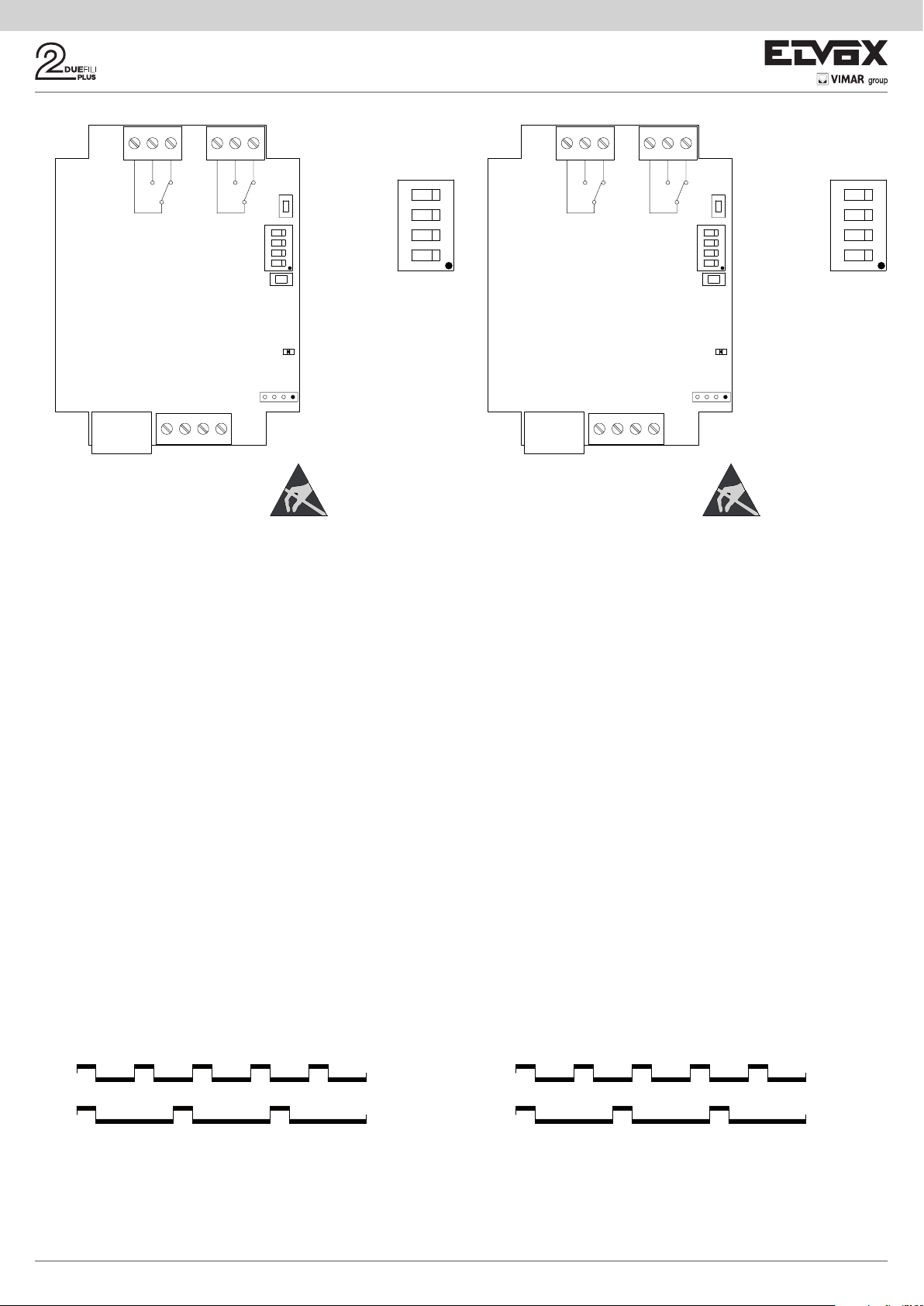
Morsettiere componenti
Component terminal blocks
4
ON
123
Contatto
Relè RL1
Contatto
Relè RL2
ID
RST
P1
Tasto di
PULSANTE DI
PROGRAMMAZIONE
programmazione
Dip-switch
DIP SWITCH
ATTRIBUZIONE
attribuzione ID
ID
PULSANTE
Tasto di
DI RESET
Reset
Segnalazione
LED INDICATORE
STATO DELLA
programmazione
PROGRAMMAZIONE
BA
C
TERMINAZIONE
Connettore
SEGNALE VIDEO
terminazione
BUS DUE FILI
ATTENZIONE: dispositivo sensibile alle scari-
che elettrostatiche.
Connettore di colle-
CONNETTORE
PROGRAMMAZIONE
gamento
CON 950C O
programmatore
950C /
SaveProg / EVCom
12 B1 B2
MORSETTIERA BUS
Morsettiera
BUS
DUE FILI
PROGRAMMAZIONI MANUALI BUS VERTICALE
1) RIPRISTINO DATI DI DEFAULT
La procedura di Reset permette di tornare alle impostazioni di fabbrica (configurazione
di default).
- Premere e mantenere premuti contemporaneamente i tasti RST e P1.
- Rilasciare RST mantenendo premuto P1 fino a quando il led inizia a lampeggiare.
- Mentre il led lampeggia rilasciare P1 e subito ripremere P1.
- Mantenere P1 premuto fino a quando il led si spegne.
- Rilasciare P1.
NOTA: nella configurazione di Default, la modalità di funzionamento è di relè monostabile con attivazione dai tasti del posto interno.
2) RELÈ MONOSTABILE CON ATTIVAZIONE DEI TASTI DA POSTO INTERNO
Il relè RL1 si attiva premendo il tasto P2 del posto interno, il relè RL2 viene attivato dal
tasto P3 del posto interno. Tutti i posti interni che prevedono i tasti P2 e P3 opportunamente configurati, possono attivare RL1 e RL2.
Esempio: premendo il tasto P2, trascorso il tempo di ritardo T1, si attiva il relè RL1,
rimane attivo per un tempo T2, dopo di che torna a riposo (nella posizione iniziale).
Lo stesso funzionamento vale per il tasto P3 che attiva RL2 con le stesse modalità
appena descritte.
3) RIPETITORE DI CHIAMATA
Il relè RL1 ripete le chiamate che arrivano ad un posto interno da un’unità elettronica
esterna. Il relè RL2 ripete le chiamate intercomunicanti. Al relè deve essere assegnato
un identificativo del Gruppo riferito all’ID del posto interno . Il relè si attiva seguendo il
ritmo di chiamata.
ATTENZIONE: prima di procedere al collegamento ed alla programmazione leggere
attentamente le istruzioni per avere un quadro completo sulle caratteristiche, funzioni
e prestazioni dell’apparecchiatura.
Il relè termina la ripetizione della chiamata quando:
- L’unità elettronica completa i cicli suoneria programmati (chiamata esterna)
- Il relè giunge al termine del numero di cicli programmati (default 5)
- Alla risposta.
Key for
PULSANTE DI
P1
PROGRAMMAZIONE
programming
Dip-switch
DIP SWITCH
ATTRIBUZIONE
ID assignment
ID
PULSANTE
Key for
DI RESET
Reset
Contact
Relay RL1
Contact
Relay RL2
ID
RST
Signal for
LED INDICATORE
BA
C
STATO DELLA
programming
PROGRAMMAZIONE
TERMINAZIONE
Connector
SEGNALE VIDEO
termination
TWO-WIRE BUS
CAUTION: Device
sensitive to electrostatic
discharges.
gura 1
Connector for con-
CONNETTORE
PROGRAMMAZIONE
necting
CON 950C O
programmer 950C /
SaveProg / EVCom
12 B1 B2
MORSETTIERA BUS
Terminal block
BUS
TWO-WIRE
VERTICAL BUS MANUAL PROGRAMMING
1) RESET DEFAULT DATA
The reset procedure allows factory settings to be restored (default configuration).
- Press and hold down buttons RST and P1 simultaneously.
- Release RST but continue to hold down P1 until the LED begins to flash.
- While the LED flashes release P1 and press P1 immediately again.
- Hold down P1 until the LED goes out.
- Release P1.
NOTE: In the Default configuration, the operating mode is as a monostable relay with
activation by the indoor station buttons.
2) MONOSTABLE RELAY WITH ACTIVATION OF BUTTONS ON INDOOR STATION
Relay RL1 is activated by pressing button P2 on the indoor station, relay RL2 by pressing button P3 on the indoor station. All the indoor stations that have buttons P2 and
P3 suitably configured can activate RL1 and RL2.
Example: on pressing button P2, after the delay time T1 the relay RL1 is activated and
remains active for a time T2, after which it returns to rest (initial position). The same ope-
ration applies for button P3, which activates RL2 in the same way as described above.
3) CALL REPEATER
Relay RL1 repeats calls arriving at an indoor station from an external electronic unit.
Relay RL2 repeats intercommunicating calls. The relay must be assigned a Group ID
referring to the ID of the indoor station. The relay activates following the call sequence.
CAUTION: Before commencing connecting and programming, read the instructions
carefully to get a clear idea of the equipment's characteristics, functions and features.
The relay terminates call repetition when:
- The electronic unit completes the programmed chime cycles (external call)
- The relay reaches the end of the number of programmed cycles (default 5)
- On answering.
ON
4
123
Figure 1
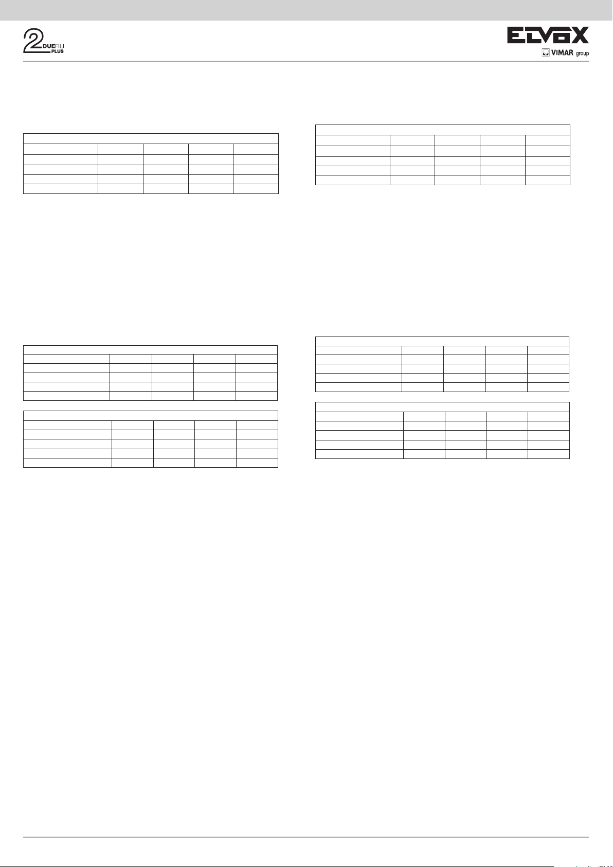
1s ON
2s OFF
1s ON
4s OFF
Chiamata
da esterno
Chiamata
interna
Nel caso siano appena descritto verrà utilizzato l’identificativo ID di default, nel caso
siano presenti più relè 69PH nell’impianto. Per i posti interni dotati di più tasti, questi
potranno essere opportunamente configurati (vedi istruzioni posti interni) creando dei
GRUPPI al fine di poter pilotare più attivazioni (relè) da un unico posto interno.
1s ON
2s OFF
1s ON
gura 2
4s OFF
In
the case that has just been described the default ID will be used, if there is more
Call
from outside
Call
from inside
than one 69PH relay in the system. For indoor stations with multiple buttons, the buttons can be suitably configured (see indoor station instructions) creating GROUPS in
order to drive multiple activations (relays) from a single indoor station.
Figure 2
3
Esempio: assegnando al Gruppo 1 del relè l’ID = 8, RL1 o RL2 si attivano all’arrivo di
una chiamata verso il posto interno con ID = 8. Ad una chiamata da unità elettronica
si attiva il relè RL1, mentre ad una chiamata da un apparecchio intercomunicante si
attiva RL2.
Programmazione ID per installazione su Bus Verticale
Il relè dispone di 4 gruppi, per cui può attivarsi per quattro ID diversi.
Tabella Programmazione ID
Gruppo Dip 1 Dip 2 Dip 3 Dip 4
Gruppo 1 OFF OFF OFF ON
Gruppo 2 ON OFF OFF ON
Gruppo 3 OFF ON OFF ON
Gruppo 4 ON ON OFF ON
Esempio: (Gruppo 1 – posto interno ID = 8)
1) Portare il dip-switch 4 in posizione ON per indicare programmazione.
2) Portare i dip-switch 1, 2 e 3 su OFF per selezionare il GRUPPO 1.
3) Premere P1 fino a quando si accende il led a luce fissa.
4) Rilasciare P1.
5) Premere il tasto serratura del posto interno ID 8 (ID di esempio per le istruzioni), il
led inizia a lampeggiare
6) Premere nuovamente P1 fino a quando il led si spegne.
7) Rilasciare P1.
Ora l’ID è stato assegnato.
8) Rimettere il dip-switch 4 su OFF.
Il relè dispone di 8 Gruppi indipendenti per RL1 e RL2. In fase di programmazione
l’ID viene assegnato automaticamente sia a RL1 che RL2. La procedura di cancellazione invece, deve essere fatta distintamente per RL1 e per RL2.
Cancellazione ID
Tabella cancellazione ID relè RL1
Gruppo Dip 1 Dip 2 Dip 3 Dip 4
Gruppo 1 Relè 1 OFF OFF OFF OFF
Gruppo 2 Relè 1 ON OFF OFF OFF
Gruppo 3 Relè 1 OFF ON OFF OFF
Gruppo 4 Relè 1 ON ON OFF OFF
Tabella cancellazione ID relè RL2
Gruppo Dip 1 Dip 2 Dip 3 Dip 4
Gruppo 1 Relè 2 OFF OFF ON OFF
Gruppo 2 Relè 2 ON OFF ON OFF
Gruppo 3 Relè 2 OFF ON ON OFF
Gruppo 4 Relè 2 ON ON ON OFF
Esempio: cancellare l’ID appena assegnato (Gruppo 1 – Relè 1 e Gruppo 1 – Relè 2)
1) Portare il dip-switch 4 in posizione OFF per indicare cancellazione.
2) Selezionare il GRUPPO 1 di RL1 portando i Dip-switch 1, 2 e 3 in posizione OFF.
3) Premere P1 fino a quando si accende il led.
4) Quando il led si spegne rilasciare il tasto P1.
A questo punto è stato resettata la programmazione di RL1.
5) Per RL2 selezionare il GRUPPO 1 di RL2 con Dip-switch 1 e 2 in posizione OFF e
Dip-switch 3 in posizione ON.
6) premere P1 fino a quando si accende il led.
7) Quando il led si spegne rilasciare il tasto P1.
A questo punto è stato resettata la programmazione anche di RL2.
8) Rimettere tutti i dip-switch su OFF.
NOTA: è possibile cancellare tutte le programmazioni presenti nel 69PH contemporaneamente utilizzando la procedura di “RIPRISTINO DATI DI DEFAULT”.
NOTA: l’attribuzione dell’ identificativo ID con 69PH installato sul Bus Orizzontale , può
avvenire solo con programmatore 950C o SaveProg.
4) ATTRIBUZIONE ID PER FUNZIONAMENTO DEI RELÈ PER PRESENZA DI PIÙ
69PH NELL’IMPIANTO
L’ID del dispositivo 69PH di default è 1
Nel funzionamento come RELE’, possono essere presenti fino a otto 69PH nell’impianto, per un totale di 16 attuatori, in questo caso con i Dip-switch deve essere assegnato un identificativo ID ad ogni modulo 69PH. Il posto interno deve avere più tasti
opportunamente programmati per attivare relè ausiliari.
NOTA: più relè possono essere programmati con lo stesso ID se c’è la necessità di
attivazioni contemporanee comandate dallo stesso tasto.
Tabella 1
Tabella 2Tabella 3
Example: if ID = 8 is assigned to Group 1 of relay, RL1 or RL2 activate on arrival of a
call to an indoor station with ID = 8. A call from an electronic unit activates relay RL1,
whereas a call from an intercom device activates RL2.
Programming ID for installation on Vertical Bus
The relay has 4 groups, so it can be activated for four different IDs.
ID programming table
Group Dip 1 Dip 2 Dip 3 Dip 4
Group 1 OFF OFF OFF ON
Group 2 ON OFF OFF ON
Group 3 OFF ON OFF ON
Group 4 ON ON OFF ON
Example: (Group 1 – indoor station ID = 8)
1) Set dip switch 4 in ON position to indicate programming.
2) Set dip switches 1, 2 and 3 on OFF to select GROUP 1.
3) Press and hold down P1 until the LED illuminates steadily.
4) Release P1.
5) Press door lock button on indoor station ID 8 (example ID for the instructions); the
LED will begin to flash
6) Press and hold down P1 again until the LED goes off.
7) Release P1.
The ID is now assigned.
8) Set dip-switch 4 back onto OFF.
The relay has 8 independent groups for RL1 and RL2. During programming, the
ID is assigned automatically to both RL1 and RL2. The cancellation procedure,
however, must be preformed separately for RL1 and RL2.
ID cancellation
Relay RL1 ID cancellation table
Group Dip 1 Dip 2 Dip 3 Dip 4
Group 1 Relay 1 OFF OFF OFF OFF
Group 2 Relay 1 ON OFF OFF OFF
Group 3 Relay 1 OFF ON OFF OFF
Group 4 Relay 1 ON ON OFF OFF
Relay RL2 ID cancellation table
Group Dip 1 Dip 2 Dip 3 Dip 4
Group 1 Relay 2 OFF OFF ON OFF
Group 2 Relay 2 ON OFF ON OFF
Group 3 Relay 2 OFF ON ON OFF
Group 4 Relay 2 ON ON ON OFF
Example: cancelling the ID that has just been assigned (Group 1 – Relay 1 and Group
1 – Relay 2)
1) Set dip switch 4 in OFF position to indicate cancellation.
2) Select GROUP 1 of RL1 by setting dip switches 1, 2 and 3 in the OFF position.
3) Press and hold down P1 until the LED lights up.
4) When the LED goes off, release button P1.
RL1 programming has now been reset.
5) For RL2, select GROUP 1 of RL2 by setting dip switches 1 and 2 in the OFF position
and dip switch 3 in the ON position.
6) Press and hold down P1 until the LED lights up.
7) When the LED goes off, release button P1.
RL2 programming has now also been reset.
8) Set all the dip-switches back onto OFF.
NOTE: All programming on 69PH can be cancelled simultaneously using the “RESET
DEFAULT DATA” procedure.
NOTE: The ID with 69PH installed over Horizontal Bus can only be assigned with programmer 950C or SaveProg.
4) ID ATTRIBUTION FOR RELAY OPERATION IF MORE THAN ONE 69PH IS PRESENT IN THE SYSTEM
The default ID of device 69PH is 1
When operating as RELAYS, there may be up to eight 69PH modules in the system,
to a total of 16 actuators. In this case the dip switches must be used to assign an ID to
each 69PH module. The indoor station must have multiple suitably programmed buttons
to activate auxiliary relays.
NOTE: More than one relay can be programmed with the same ID if simultaneous
activations controlled by the same button are required.
Table 1
Table 2Table 3
NOTA: RL1 e RL2 in configurazione DEFAULT vengono attivati dai tasti del posto
interno P2 e P3 corrispondenti ad AUX 1 e AUX2 di ogni GRUPPO configurato.
L’attribuzione manuale dell’identicativo ID del Modulo relè 69PH, avviene attraverso
il settaggio dei “Dip-switch di attribuzione identicativo ID”. Per la congurazione fare
riferimento a gura 1 ed a tabella 4.
4
NOTE: RL1 and RL2 are activated in the DEFAULT configuration by buttons P2 and P3
on the indoor station, corresponding to AUX 1 and AUX 2 of each configured GROUP.
The ID of the relay module 69PH is manually assigned by setting the "Dip-switch for
assigning ID." For the conguration please refer to Figure 1 and Table 4.
69PH Funzionamento Dip 1 Dip 2 Dip 3 Dip 4
1 (ID 1)
2 (ID 2)
3 (ID 3)
4 (ID 4)
5 (ID 5)
6 (ID 6)
7 (ID 7)
8 (ID 8)
RL1=Ausiliario 1 e RL2=Ausiliario 2
RL1=Ausiliario 3 e RL2=Ausiliario 4
RL1=Ausiliario 5 e RL2=Ausiliario 6
RL1=Ausiliario 7 e RL2=Ausiliario 8
RL1=Ausiliario 9 e RL2=Ausiliario 10
RL1=Ausiliario 11 e RL2=Ausiliario 12
RL1=Ausiliario 13 e RL2=Ausiliario 14
RL1=Ausiliario 15 e RL2=Ausiliario 16
OFF OFF OFF OFF
ON OFF OFF OFF
OFF ON OFF OFF
ON ON OFF OFF
OFF OFF ON OFF
ON OFF ON OFF
OFF ON ON OFF
ON ON ON OFF
Tabella 4
PROGRAMMAZIONI CON PROGRAMMATORE ART.
950C / “SAVEPROG” - BUS VERTICALE
5) RELÈ MONOSTABILE CON ATTIVAZIONE DA TASTI DEL POSTO INTERNO
È la modalità di funzionamento programmata di fabbrica. I relè si attivano con un ritado T1 e rimangono attivi per un tempo T2 poi tornano a riposo.
Il relè RL1 si attiva premendo il tasto P2 del posto interno, il relè RL2 viene attivato dal
tasto P3 del posto interno. Tutti i posti interni che prevedono i tasti P2 e P3 opportunamente configurati, possono attivare RL1 e RL2.
I relè RL1 e RL2 possono funzionare in questa modalità anche singolarmente.
6) RELÈ MONOSTABILE ATTIVATO DA CHIAMATA
Il relè viene attivato dall’invio di un chiamata ad un posto interno presente nell’impianto
che accetta la chiamata. Si attiva con un tempo di ritardo T1 rispetto all’invio della
chiamata e rimane attivo per un tempo T2. Dopo di che il relè torna nella posizione
iniziale. I dispositivi che inviano la chiamata e i dispositivi che ricevono la chiamata sono
configurabili da “mappa delle abilitazioni”.
Per default tutti i dispositivi sono abilitati.
7) RELÈ MONOSTABILE ATTIVATO DAI TASTI F1, F2, SERRATURA DEL POSTO
INTERNO
Il relè si attiva quando viene inviato il comando apertura serratura o F1 o F2 premendo il
tasto corrispondente del posto interno. Il relè si attiva con ritardo T1 rispetto la ricezione
del comando e rimane attivo per un tempo T2.
I dispositivi che inviano il comando e quelli che sono destinatari del comando sono configurabili secondo la “Mappa delle abilitazioni”. Per default tutti i dispositivi sono abilitati.
8) RELÈ MONOSTABILE ATTIVATO DA TENTATIVO DI CHIAMATA
Il relè si attiva all’invio di una chiamata ad un dispositivo che può non essere presente
nell’impianto o rifiutare la chiamata. Il relè si attiva con un tempo di ritardo T1 rispetto
all’invio della chiamata e rimane attivo per il tempo T2. I dispositivi che inviano la chiamata e quelli che ricevono la chiamata sono abilitati da “Mappa delle abilitazioni”. Per
default tutti i dispositivi sono abilitati.
9) RELÈ MONOSTABILE ATTIVATO DA TENTATIVO DI CHIAMATA A GRUPPO
Il relè si attiva all’invio di una chiamata ad un posto interno che può non essere presente
nell’impianto o rifiutare la chiamata. Il relè si attiva con un tempo di ritardo T1 rispetto
all’invio della chiamata e rimane attivo per il tempo T2.
L’ID del posto interno destinatario della chiamata deve essere programmato nel parametro “GRUPPO”. È possibile avere fino ad 8 posti interni diversi.
10) RELÈ BISTABILE CON ATTIVAZIONE DA TASTI POSTO INTERNO
Il relè commuta il suo stato ogni volta che riceve un comando a lui indirizzato (vedi
paragrafo 4 “Tabella programmazione ID”).
Esempio: il relè RL1 non è attivo, il tasto P2 è stato programmato per attivare AUSILIARIO 1. Premendo P2, RL1 si attiva con un ritardo T1. Premendo nuovamente P2
il relè si disattiva con un ritardo T2. In questa modalità di funzionamento il RELE’ può
inviare un messaggio di conferma dell’avvenuta commutazione al dispositivo che lo ha
attivato, attivando il flag “Not. Stato”.
11) RELÈ BISTABILE ATTIVATO DA CHIAMATA ACCETTATA
Il relè si attiva all’invio di una chiamata ad un dispositivo presente sull’impianto che
accetta la chiamata.
La disattivazione del relè può avvenire in modo diverso a seconda dello stato del Flag
“Chiam. Int”:
- Se il Flag “Chiam. Int” = NO: il relè si disattiva al completamento dei cicli suoneria
impostati sulla unità elettronica (se chiamata esterna) oppure alla risposta alla chiamata oppure al termine della chiamata.
- Se il Flag “Chiam. Int” = SI: il relè si disattiva solo al termine della chiamata.
I dispositivi che inviano la chiamata e quelli che ricevono la chiamata sono abilitabili da
“Mappa delle abilitazioni”. Per default tutti i dispositivi sono abilitati.
12) RIPETITORE DI CHIAMATA STANDARD
Il relè RL1 ripete le chiamate che arrivano al posto interno da una unità elettronica
esterna. Il relè RL2 ripete le chiamate interne.
Per far funzionare il relè in questa modalità è necessario assegnare l’ID al parametro
GRUPPO del relè 1 e al corrispondente parametro GRUPPO del relè 2 l’ID del dispositivo che riceve la chiamata. In ogni GRUPPO l’ID di RL1 e RL2 deve corrispondere.
Esempio:
- Gruppo 1 RL1 = Gruppo 1 RL2 = 1
- Gruppo 2 RL1 = Gruppo 2 RL2 = 3
- Gruppo 3 RL1 = Gruppo 3 RL2 = 0
- Gruppo 4 RL1 = Gruppo 4 RL2 = 0
Il relè RL1 si attiva per la chiamata esterna all’ID 1 e 3.
Il relè RL2 si attiva per la chiamata interna all’ID 1 e 3.
69PH Operation Dip 1 Dip 2 Dip 3 Dip 4
1 (ID 1)
2 (ID 2)
3 (ID 3)
4 (ID 4)
5 (ID 5)
6 (ID 6)
7 (ID 7)
8 (ID 8)
RL1=Auxiliary 1 and RL2=Auxiliary 2
RL1=Auxiliary 3 and RL2=Auxiliary 4
RL1=Auxiliary 5 and RL2=Auxiliary 6
RL1=Auxiliary 7 and RL2=Auxiliary 8
RL1=Auxiliary 9 and RL2=Auxiliary 10
RL1=Auxiliary 11 and RL2=Auxiliary 12
RL1=Auxiliary 13 and RL2=Auxiliary 14
RL1=Auxiliary 15 and RL2=Auxiliary 16
OFF OFF OFF OFF
ON OFF OFF OFF
OFF ON OFF OFF
ON ON OFF OFF
OFF OFF ON OFF
ON OFF ON OFF
OFF ON ON OFF
ON ON ON OFF
Table 4
PROGRAMMING WITH PROGRAMMER ART. 950C /
"SAVEPROG" - VERTICAL BUS
5) MONOSTABLE RELAY WITH ACTIVATION BY BUTTONS ON INDOOR STATION
THIS is the factory set operating mode. The relays activate with a delay time T1 and
remain active for a time T2 before returning to rest.
Relay RL1 is activated by pressing button P2 on the indoor station, relay RL2 by pressing button P3 on the indoor station. All the indoor stations that have buttons P2 and
P3 suitably configured can activate RL1 and RL2.
In this mode relays RL1 and RL2 can also operate individually.
6) CALL-ACTIVATED MONOSTABLE RELAY
The relay is activated when a call is sent to an indoor station present in the system,
which accepts the call. It activates with a delay time T1 after the call is sent and remains
active for a time T2. After that, the relay returns to its initial position. The devices that
send the call and the devices that receive the call can be configured via the “enabling
map”.
By default all devices are enabled.
7) MONOSTABLE RELAY ACTIVATED BY F1, F2 OR LOCK BUTTONS ON THE
INDOOR STATION
The relay activates when the door lock opening or F1 or F2 commands are given by
pressing the corresponding button on the indoor station. The relay activates with a delay
time T1 after receiving the command and remains active for a time T2.
The devices that send and receive the command can be configured according to the
“Enabling map”. By default all devices are enabled.
8) MONOSTABLE RELAY ACTIVATED BY CALL ATTEMPT
The relay activates when a call is sent to a device that may not be present in the system
or may decline the call. The relay activates with a delay time T1 after the call is sent and
remains active for a time T2. The devices that send and receive the call are enabled
according to the “enabling map”. By default all devices are enabled.
9) MONOSTABLE RELAY ACTIVATED BY ATTEMPT TO CALL GROUP
The relay activates when a call is sent to an indoor station that may not be present in
the system or may decline the call. The relay activates with a delay time T1 after the
call is sent and remains active for a time T2.
The ID of the indoor station that receives the call must be programmed in the “GROUP”
parameter. It is possible to have up to 8 different indoor stations.
10) BISTABLE RELAY WITH ACTIVATION BY INDOOR STATION BUTTONS
The relay switches its state every time it receives a command sent to it (see paragraph
4 “ID programming table”).
Example: Relay RL1 is not active, button P2 has been programmed to activate AUXILIARY 1. On pressing P2, RL1 activates with a delay time T1. On pressing P2 again,
the relay deactivates with a delay time T2. In this operating mode the RELAY can send
a switching confirmation message to the device that has activated it, activating the
“Not.Status” flag.
11) BISTABLE RELAY ACTIVATED BY ACCEPTED CALL
The relay activates when a call is sent to a device present in the system, which then
accepts the call.
The relay can be deactivated differently according to the status of the “Int.Call” flag:
- If the “Int. Call" Flag = NO: the relay deactivates on completion of the chime cycles
set on the electronic unit (if an external call), when the call is answered or at the end
of the call.
- If the “Int. Call" Flag = YES: the relay deactivates only at the end of the call.
The devices that send the call and those that receive the call are enabled according to
the “Enabling map”. By default all devices are enabled.
12) STANDARD CALL REPEATER
Relay RL1 repeats calls arriving at an indoor station from an external electronic unit.
Relay RL2 repeats internal calls.
To make the relay operate in this mode, the ID of the device receiving the call must be
assigned to the GROUP parameter of relay 1 and to the corresponding GROUP parameter of relay 2. In each GROUP the ID of RL1 and RL2 must match.
Example:
- Group 1 RL1 = Group 1 RL2 = 1
- Group 2 RL1 = Group 2 RL2 = 3
- Group 3 RL1 = Group 3 RL2 = 0
- Group 4 RL1 = Group 4 RL2 = 0
Relay RL1 activates in the event of an external call to ID 1 and 3.
Relay RL2 activates in the event of an internal call to ID 1 and 3.
5
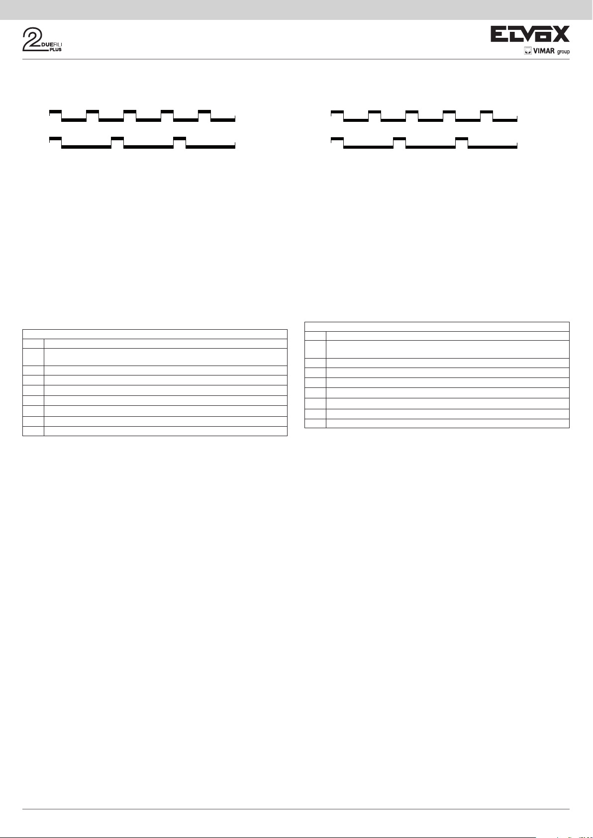
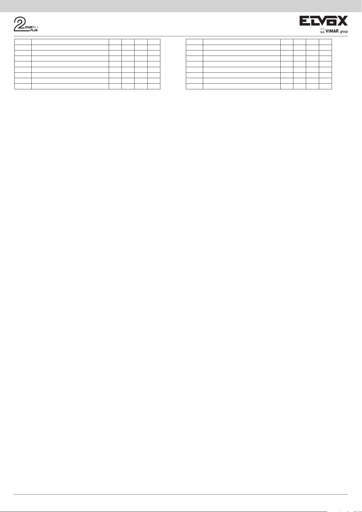
È possibile programmare fino a 8 identificatori diversi. Il relè termina la ripetizione della
CHIAMATA DA ESTERNO
CHIAMATA INTERNA
CHIAMATA DA ESTERNO
CHIAMATA INTERNA
chiamata quando:
L ‘unità elettronica completa i cicli suoneria programmati (se chiamata esterna),
quando il relè termina il numero di cicli programmati (default 5), alla risposta.
1s ON
2s OFF
1s ON
4s OFF
Chiamata
da esterno
Chiamata
interna
Up to 8 different identifiers can be programmed. The relay terminates call repetition
when:
The electronic unit completes the programmed chime cycles (if external call), when
the relay terminates the programmed number of cycles (default 5), on answering.
gura 3
1s ON
2s OFF
1s ON
4s OFF
Call
from outside
Call
from inside
Figure 3
13) RIPETITORE DI CHIAMATA GENERICO
Il relè RL1 ripete la chiamata esterna, il relè RL2 ripete la chiamata interna. Per far
questo l’ID del GRUPPO deve coincide per RL1 e RL2. Quando questo non avviene
anche per uno solo dei relè (tra RL1 ed RL2), compariranno in SaveProg le check
box EXT, INT, 6120 da spuntare per l’abilitazione. Questa operazione è necessaria
altrimenti RL1 e RL2 saranno attivati dalle sole chiamate esterne. Per quanto riguarda
il funzionamento del 950C, si possono configurare i relè secondo tabella x, e l’abilitazione alle funzioni è subordinata ad almeno uno degli ID di un GRUPPO sia diversa
tra RL1 e RL2.
Attivazione: attraverso l’attribuzione degli identificativi ID nel menù GRUPPO. Possono
essere creati fino a 8 GRUPPI (4 in modalità manuale). Quando solo uno degli ID in un
GRUPPO non è corrispondente tra RL1 con RL2, si dovrà procedere:
950C: dal Menù Tipo Rip. Chiam. = Rip.Ch.per Grp. 1, 2 , 3... deve essere indicato con
riferimento a tabella x, la modalità da attribuire per ogni singolo ID corrispondente agli
ID attivati nel GRUPPO.
SaveProg: su GRUPPO si indicano per RL1 e RL2 gli ID per cui si i relè si devono
attivare all’arrivo di una chiamata. Quando solo uno degli ID in un GRUPPO non è
corrispondente tra RL1 con RL2, compariranno per EST, INT, 6120 le check box da
spuntare per attivare il tipo di funzione ESTERNO, INTERNO, 6120 una o più scelte
contemporanee. NOTA: il numero 0 disabilita il comando.
Tabella programmazione parametro “Tipo Rip. Chiamata”
Set Funzione
0 (Default) Ripete le chiamate da esterno per i dispositivi programmati nel
parametro GRUPPO
1 Ripete le chiamate da ESTERNO per GRUPPO
2 Ripete le chiamate da INTERCOMUNICANTI
3 Ripete le chiamate da ESTERNO e INTERCOMUNICANTI
4 Ripete le chiamate da 6120
5 Ripete le chiamate da ESTERNO e da 6120
6 Ripete le chiamate da INTERCOMUNICANTI e da 6120
7 Ripete le chiamate da ESTERNO, da INTERCOMUNICANTI e da 6120
Nota: Il numero di squilli nella modalità INTERCOMUNICANTE e con 6120 è subordinato al parametro CICLI DI SUONERIA. La ripetizione della chiamata con 6120 richiede
lo spunto del FLAG “GRUPPO FUORIPORTA” nella programmazione dei posti interni
(vedi istruzioni dell’unità elettronica se alfanumerica o 950C/SaveProg se si programma
da unità elettronica a tasti). Per la programmazione dell’art. 6120 fare riferimento alle
istruzioni del prodotto. Nota: il numero di CICLI SUONERIA è riferito al numero commutazioni del relè.
14) RIPETITORE DI CHIAMATA DA ART. 6120
Il relè viene attivato da una chiamata inviata da un tasto “fuori porta” per mezzo del
modulo art. 6120 ad un dispositivo che può anche non essere presente nell’impianto
o rifiutare la chiamata. Il relè si disattiva completati i cicli suoneria programmati nel
parametro cicli suoneria. Non è necessaria l’attivazione del flag “gruppo fuori porta”
nella programmazione del posto interno. I 6120 che inviano la chiamata ed i dispositivi
destinatari sono abilitati da “Mappa delle abilitazioni”. Per default tutti i dispositivi sono
abilitati.
15) Modalità Tapparella
Modalità di funzionamento per il controllo di tapparelle, serrande, tende da sole, ecc. Il
funzionamento dei due relè RL1 e RL2 è in “interblocco”, per evitare l’attivazione contemporanea dei due relè. Premendo il tasto di attivazione del relè RL1, questo commuta
con un tempo ritardo T1 mantenendo questa posizione per un tempo T2 o fino a che
non si preme nuovamente lo stesso tasto di attivazione. Il relè in stato di attivazione si
disattiva anche premendo il tasto di comando dell’altro relè. Nel caso in cui i due relè
comandino i due sensi di rotazione di un motore (per esempio il motoriduttore di una
tapparella) si consiglia di mantenere un tempo di ritardo minimo di attivazione del relè
(default = 1s), in modo che il motore nell’inversione del senso di rotazione, passi per
uno stato di fermo.
16) MAPPA DELLE ABILITAZIONI
E’ possibile abilitare o disabilitare posti interni, unità elettroniche, ausiliari, centralini.
Le modalità di selezione sono due; indicando singolarmente gli identificativi ID o
previa finestra operativa di intervento dove indicare il numero di ID iniziale e finale.
La selezione tra le due modalità viene definita nel sottomenu “Tipo mappa abilitazioni
(vedi Diagramma della programmazioni con 950C) andando ad indicare “a finestra”
o a “ID singolo”. Nella modalità a singolo ID, dopo essere entrati nei sottomenu INTERNI, TARGHE, AUSILIARI, CENTRALINI, si deve introdurre il numero ID di ogni
singolo apparecchio da disabilitare. Nella modalità a finestra, dai sottomenu INTERNI,
TARGHE, AUSILIARI, CENTRALINI, sono disponibili 3 finestre (FIN #1, FIN #2, FIN
# 3) dove per ognuna può essere inserito l’identificativo ID iniziale e l’identificativo ID
finale in modo da configurare la “finestra operativa”. Si conferma con OK.
NOTA: Il numero di fine non può essere inferiore al numero di inizio.
Per avere tutti i numeri abilitati, basterà inserire il numero 1 nella prima abilitazione ed
il numero massimo nella seconda abilitazione di FIN# 1.
13) GENERIC CALL REPEATER
The relay RL1 repeats the external call, the relay RL2 repeats the internal call. To do
this, the ID of the GROUP must coincide for RL1 and RL2. When this does not occur
even for only one of the relays (between RL1 and RL2), the check boxes EXT, INT and
6120 will appear in SaveProg to be checked for enabling. This is necessary otherwise
RL1 and RL2 will be activated only by external calls. Regarding the functioning of the
950C, the relays can be configured according to table x, and function enabling is subject
to at least one of a the IDs of a GROUP being different between RL1 and RL2.
Activation: by assigning the IDs in the GROUP menu. Up to 8 GROUPS (4 in manual
mode) can be created. When only one of the IDs in a GROUP does not match between
RL1 with RL2, the following will be necessary:
950C: from the Menu Type Call Rep. = Call Rep. for Grp. 1, 2 , 3... the mode to assign
must be specified with reference to table x for each single ID corresponding to the
activated IDs in the GROUP.
SaveProg: the IDs for which the relays must be activated when a call arrives are indi-
cated for RL1 and RL2 on the GROUP. When only one of the IDs in a GROUP does not
match RL1 or RL2, for EXT, INT and 6120 the check boxes will appear to be checked in
order to activate the EXTERNAL, INTERNAL, 6120 type of function with one or multiple
choices. NOTE: The number 0 disables the command.
Table for programming parameter "Call Rep. Type”
Set Function
0 (Default) Repeats external calls for devices programmed in the
GROUP parameter
1 Repeats EXTERNAL calls for GROUP
2 Repeats INTERCOM calls
3 Repeats EXTERNAL and INTERCOM calls
4 Repeats calls from 6120
Tabella 5
5 Repeats EXTERNAL calls and calls from 6120
6 Repeats INTERCOM calls and calls from 6120
7 Repeats EXTERNAL and INTERCOM calls and calls from 6120
Note: The number of rings in INTERCOM mode and with 6120 is determined by the
CHIME CYCLES parameter. Call repetition with 6120 requires the “LANDING GROUP”
FLAG to be checked in indoor station programming (see electronic unit instructions
when using an alphanumeric panel or 950C/SaveProg when using an electronic unit
with buttons for programming). For programming art. 6120, refer to the product instructions. Note: The number of CHIME CYCLES refers to the number of relay switches.
14) CALL REPEATER FROM ART. 6120
The relay is activated by a call sent from a "landing" button via module art. 6120 to a
device that may not even be present in the system or reject the call. The relay deactivates after completing the number of chime cycles programmed by the chime cycle
parameter. It is not necessary to activate the "landing group" flag when programming
the indoor station. The 6120 modules that send the call and the recipient devices are
enabled according to the “Enabling map”. By default all devices are enabled.
15) Roller shutter mode
Operating mode to control roller blinds, shutters, awnings, etc. The operation of the
two relays RL1 and RL2 is "interlocked" to avoid simultaneous activation of the two
relays. When relay RL1 activation button is pressed, it switches with a delay time T1,
then maintains this position for a time T2 or until the same activation button is pressed
again. When in an activated state, the relay is also deactivated by pressing the control
button of the other relay. If the two relays control the two directions of rotation of a motor
(e.g. the reduction gear of a roller shutter), it is advisable to maintain a minimum relay
activation delay time (default = 1s) so that the motor passes through a stationary state
when reversing its direction of rotation.
16) ENABLING MAP
It is possible to enable or disable indoor stations, electronic units, auxiliary devices
and switchboards. There are two selection procedures, indicating the IDs individually
or after an operating window where you indicate the initial and final ID number. Selecting between the two modes is defined in the "Enabling map type" submenu (see
diagram for programming with 950C) indicating with a "window" or a "single ID". In
the single ID mode, after entering the INTERNAL, ENTRANCE PANEL, AUXILIARY,
SWITCHBOARD submenu you must enter the ID number of each device to disable.
In window mode, from the INTERNAL, ENTRANCE PANEL, AUXILIARY, SWITCHBOARD submenus, there are 3 windows (WIN #1, WIN #2, WIN # 3) where for each
one you can enter the initial and final ID so as to configure the "operating window".
Confirm with OK.
NOTE: The end number must not be any less than the start number.
To have all the numbers enabled, simply enter number 1 in the first enable and the
maximum number in the second enable of WIN# 1.
Table 5
6
 Loading...