

Page 1
MULTIFUNCTION DEVICE:
www.leedan.com info@leedan.com Toll-Free: 800-231-1414
Type 6949
MULTIFUNCTION
DEVICE
Type 6949
TECHNICAL SPECIFICATIONS
Type 6949 is a programmable
multifunction device for use with
DIGIBUS systems. The device
solves specific requirements in
DIGIBUS systems.
Type 6949 can be used as:
- Converter of codes from 4 to 8 digits and vice versa. Type
6949 enables the combination of interphones and monitors with
4-digit encoding/decoding with entrance panels and switchboards with 8-digit encoding/decoding. Type 6949 converts the
call codes and the commands F1, F2 and door lock release, from
4 to 8 digits and vice versa by adding or removing the 4 digits set
in the parameter "Predigit".
- Pseudo stairway entrance panel with 8-digit encoding. Type
6949 is used as a stairway entrance panel (secondary) in building complex type systems with 8-digit encoding/decoding,
where there are buildings with secondary entrances fitted with
stairway panels and buildings without stairway panels. Type 6949
performs all functions of a standard stairway panel without the
need for a secondary input.
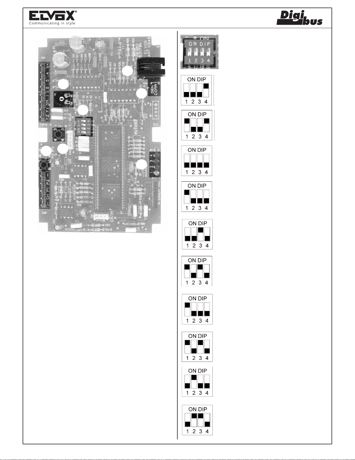
CONTROLS AND ADJUSTMENTS
A - B) Pushbuttons for programming parameters of type 6949.
C) Trimmer for adjustment of current generator (typical value
25mA D.C., already factory-set).
D) DIP-switch for function programming.
E) LED for function programming phase.
F) ON/OFF jumper for current generator on/off activation (ON
= jumper activated, OFF = jumper deactivated).
G) Connector for connection of programmer type 950B.
TERMINALS
+I) The terminal is activated to switch off the monitor connec-
ted to the cable riser at the start of a call and at the end of
a conversation. The terminal is connected to power supply
6948 if specified on the diagram.
CH) The terminal is activated when a call is made from the
entrance panel or when the entrance panel is used to call
an internal unit via a main entrance panel or switchboard.
The terminal remains active for the time set in parameter
7. The terminal is connected to power supply 6941 or 6948
if specified on the diagram.
P1, P2) The terminals enable control, by means of two external
switches, of the conversion of functions in switchboard call
mode. To be used when there is more than one switchboard in the same system.
- Pseudo stairway entrance panel with 4-digit encoding. As per
the above application but for systems with 4 digit encoding/decoding.
- Digital signal amplifier with 8-digit encoding. Type 6949 is
used in systems where the same cable riser column has a high
number of interphones or monitors and there is the need to
amplify/regenerate the digital signal with 8-digit encoding/decoding. If the parameters "Initial user" and "Final user" are used,
type 6949 filters the call codes, passing on only those within the
set range.
- Digital signal amplifier with 4-digit encoding. As per the
above application but for systems with 4 digit encoding/decoding.
.
- Call filter with switchboards in parallel. Type 6949 is used to
filter calls from interphones or monitors to switchboards type
945B when there is more than one switchboard in parallel in the
same system (maximum 4 switchboards). A 6949 is connected to
each switchboard between the switchboard and the interphone/&monitor cable riser, which will filter the calls, auxiliary
commands (F1, F2, F3, F4, F5) and the door lock release control
from the interphones/monitors, to use them as switchboard calls.
The filter control is managed by the parameter "Predigit". If two
external switches are connected to terminals P1 and P2 of type
6949, the filter configuration can be modified in remote mode,
enable switching of calls from one switchboard to another.
-) Common contact terminal for P1 and P2.
F2) The terminal is activated when type 6949 receives the code
for the second auxiliary function. The terminal remains
active for the time set in parameter 5. The terminal is
connected to power supply 6941, 6942 or 6948 if specified
on the diagram.
F1) The terminal is activated when type 6949 receives the code
for the first auxiliary function. The terminal remains active
for the time set in parameter 5. The terminal is connected
to power supply 6941, 6942 or 6948 if specified on the
diagram.
SR) The terminal is activated when type 6949 receives a door
lock release code. The terminal remains active for the time
set in parameter 6. The terminal is connected to power
supply 6941, 6942 or 6948 if specified on the diagram.
1) The terminal enables digital communication between the
switchboard, monitor, interphone, digital distributor and the
stairway entrance panel.
6) The terminal enables the transmission and reception of
digital codes between type 6949 and the switchboard or
between type 6949 and a main entrance panel.
5) Supply voltage terminal. The supply voltage
must be between 11.5V D.C. and 13.5V D.C.
4) Negative supply voltage terminal.
V+) +5V D.C. output terminal. Connected only if specified on
the wiring diagram
Page 2
C
www.leedan.com info@leedan.com Toll-Free: 800-231-1414
MULTIFUNCTION DEVICE:
Type 6949
G
F
Configuration
The operating mode of type 6949 is selected on
the DIP-switch (as shown in the figures below).
Operation as converter of codes from 4 to 8 digits
and vice versa, from panel to panel. Converts
codes without activation of terminals CH and +I.
D
B
A
E
PRELIMINARY OPERATIONS
On completion of installation of all devices and connections, power
up the system, and check, by means of the LEDs on the power
supplies, that all the power supplies used are in fact supplying
power.
Before programming devices, wait at least ten seconds after the
system has been powered up.
Then check and, if necessary, program the operating parameters of
the entrance panels and/or switchboard.
The interphone and monitor call codes should be programmed
after programming (if required) the technical parameters of the
entrance panels and/or switchboard and other specific devices.
PROGRAMMING
Type 6949 requires two programming phases: configuration of the
device type and technical parameter programming.
Operation as converter of codes from 4 to 8 digits
and vice versa, from panel to interphones/monitors. Enables replacement of a panel by converting
the codes and executing commands CH and +I.
Digital signal amplifier with 4-digit encoding, from
panel to panel. Executes code repetition without
activation of terminals CH and +I.
Digital signal amplifier with 4-digit encoding, from
panel to interphones/monitors. Enables replacement of a panel by repeating the codes and executing commands CH and +I.
Digital signal amplifier with 8-digit encoding, from
panel to panel. Executes code repetition without
activation of terminals CH and +I.
Digital signal amplifier with 8-digit encoding, from
panel to interphones/monitors. Enables replacement of a panel by repeating the codes and executing commands CH and +I.
Pseudo stairway panel for building complexes with
4-digit encoding.
Pseudo stairway panel for building complexes with
8-digit encoding.
Configuration
The operating mode of type 6949 is selected on the DIP-switch (as
shown in the figures below).
Call filter with switchboards type 945B in parallel
and 4-digit encoding.
Call filter with switchboards type 945B in parallel
and 8-digit encoding.
Page 3

MULTIFUNCTION DEVICE:
www.leedan.com info@leedan.com Toll-Free: 800-231-1414
Type 6949
Technical parameter programming
The technical parameters are programmed according to the configuration of type 6949. There are three programming modes: via the
keypad on a main entrance panel (type 8946, type 8942, 3942, 3946) or a porter switchboard (type 945B), with programmer type 950B, or
with a Personal Computer by means of type 94CT.
A) Programming with panel or switchboard.
Programming is via an entrance panel or a switchboard connected to terminal 6 of type 6949. The following settings are recommended
with the switchboard or panel in the vicinity of type 6949.
Entry to programming mode:
1) Press pushbutton "PS4-Reset" (point B of figure on page 91).
2) Wait for LEDs 1 and 4 to flash simultaneously.
3) Press and hold pushbutton "P1" (point A of figure on page 91), until LED 1 (green) illuminates.
Repeat the operation from point 1 if the LED does not light up within approx. 5 seconds.
4) On illumination of the LED release the pushbutton.
In the following conditions, type 6949 is set to parameter 1; to move through the parameters in sequence, press pushbutton "P1" as required.
The parameter number is indicated by illumination of the LEDs, as shown in the table below. To modify the value of a parameter, enter the
code on the panel or switchboard and press "C" to confirm. Confirmation of reception and memorisation of the code is indicated by deactivation of the LED(s). Each time a code is memorised, type 6949 exits programming mode; to program other parameters, repeat the procedure from point 1. To exit programming mode without modifying parameters, press the pushbutton "PS4-Reset".
LED
1234
1234
1234
1234
1234
1234
1234
1234
N°
parameter
1
2
3
4
5
6
7
8
Minimum
value
0
1
1
0
1
1
1
-
Maximum
value
9999
99999999
99999999
99999999
255
255
255
-
Default
value
0
1
99999999
0
1
1
1
-
N° parameter
Predigit number
Initial user
Final user
Panel number
Time of functions
F1 and F2
Door locktime
Ringtone duration
Programming
parameter
Description
Description-Used as converter from 4 to 8 digits, modifies codes from/to panel or switchboard from 4 to 8
digits. Used as filter for calls to switchboards, modifies
calls and functions as specified in the table on page
71.
Minimum number of call (filter on calls in transit from
terminal 6 to 1).
Maximum number of call (filter on calls in transit from
terminal 6 to 1).
ID code of type 6949 (for calls/analysis from switchboard).
Time of activation of functions F1 and F2 in seconds.
Time of door lock activation in seconds.
Time of activation of call signal in seconds.
Enables programming of type 6949 with previous
programmer type 950.
LED on
B) Programming with programmer 950B.
Power up type 6949 and connect it to the programmer type 950B by means of the plug connector (point G of the figure on page 91).
1) Wait for the text "ELVOX 950B PRG" to appear on the programmer display.
2) Press one of the arrow keys (up or down) on the programmer to display the text "PROGRAM. PARAM."
3) Press the pushbutton "OK" on the programmer and wait for the text "PROGRAM [Tecn. Prog.]" to be displayed
4) Press the down arrow key to scroll through the parameters listed in the table below.
5) To modify and assign a new value to the parameter, use the numerical keys.
6) To confirm modifications and move on to the next parameters, press "OK".
7) To exit the programming mode, press "EXIT".
N.B. the parameters can only be scrolled though from top to bottom, without the option to move back through the list; to return to a previous
parameter, exit the programming mode and re-enter.
LED off
Page 4

MULTIFUNCTION DEVICE:
www.leedan.com info@leedan.com Toll-Free: 800-231-1414
Type 6949
N°
parameter
1
2
3
4
5
6
7
8
9
Display
950B
Initial user
Final user
Panel number
Digit number
--->--------
---->-------
Panel prefix
----->------
English
Minimum
value
1
1
0
0
-
-
1
-
0
Maximum
value
99999999
99999999
99999999
9999
-
-
99
-
1
Default
value
1
99999999
0
0
-
-
0
-
1
Description
Minimum number of call (filter on calls in transit from terminal 6 to 1).
Maximum number of call (filter on calls in transit from terminal 6 to 1).
ID code of type 6949 (for calls/analysis from switchboard).
Used as converter from 4 to 8 digits, modifies codes from/to panel or
switchboard from 4 to 8 digits. Used as filter for calls to switchboards,
modifies calls and functions as specified in the table on page 71.
Not used
Not used
Enables changeover of codes with the same first two digits equal to
the value set in the parameter, also when the codes are outside the
range between the initial and final users. If the value is 0 the function
is disabled.
Not used
Modifies the descriptions on the display of 950B.
0 = Italian
1 = English
10
11
12
13
14
15
16
17
18
19
20
21
22
23
24
25
26
->----------
-->---------
Door lock enable
------------
-->---------
--->--------
---->-------
----->------
----->------
------>-----
Ringtone duration
------------
Time of function F1
Time of function F2
Door locktime
------------
Reserved parameter
-
-
0
-
-
-
-
-
-
-
1
-
1
1
1
-
0
-
-
3
-
-
-
-
-
-
-
255
-
255
255
255
-
255
-
Not used
-
Not used
Door lock enable - For building complexes, enables activation of the door
1
lock in sequence (0 = No, 1 = Yes). If the value is set to 3 the door lock
opening "in reverse" is also enabled, i.e. from a switchboard below.
Not used
-
Not used
-
Not used
-
Not used
-
Not used
-
Not used
-
Not used
-
Time of activation of call signal
1
Not used
-
Time of activation of function F1 in seconds.
1
Time of activation of function F2 in seconds.
1
Time of door lock activation in seconds.
1
Not used
-
Not used
1
C) Programming with software 94CT.
See description of type 94CT.
Page 5

MULTIFUNCTION DEVICE:
www.leedan.com info@leedan.com Toll-Free: 800-231-1414
Type 6949
SWITCHBOARD CALL CONVERSION TABLE
Value of
parameter
Predigit and
Digit Preset
0001
0002
0003
0004
0005
0006
0007
0008
0009*
* Set the value PREDIGIT to 0009 in the case of 4 switchboards
in parallel.
Using two external switches, connected to terminals P1 and P2,
commands received from other switchboards in parallel can also be
switched to output to the switchboard as interphone calls, as shown
in the following table.
Value of
parameter
Predigit and
Digit Preset
0001
0002
0003
In the case of 4 switchboards in parallel, the switchboard that receives the calls from interphones via commands F3/F4/F5 cannot
receive other commands if the external switches are used; vice
versa the other switchboards receive the commands F3/F4/F5 (not
converted).
Command
converted to
Switchboard call
Switchboard call
Switchboard call
Switchboard call
Switchboard call
F1
F1
F2
F2
F3 e F4 e F5
Command conver-
ted to Switchboard
call with terminal P1
F2
F2
F1
Command passed
without conversion
None
F1
F2
F1 e F2
None
F2
None
F1
None
Command converted
to Switchboard call
with terminal P2
F1
Switchboard call
Switchboard call
Entrance panel number (4). This is the identification code of type
6949 to be programmed when using switchboard type 94CT, to
enable remote programming and analysis of type 6949 parameters.
NB: Note that the panel number must be individual and different
from the call codes of the interphones and monitors.
Digit Preset (1). The meaning of this parameter changes according
to the application of type 6949.
If type 6949 is used as a converter from 4 to 8 digits (and vice
versa), the parameter is used to identify the first 4 digits of the 8 of
the call/function codes.
Example: if the parameter is 1213 and the 4-digit code of the interphone is 0720, the call code received from an 8-digit switchboard is
12130720.
If type 6949 is used as a filter for calls to switchboards, the following
parameter controls the conversion of the functions in switchboard
call mode according to the table alongside.
Panel prefix. Enables changeover of codes with the first two digits
equal to the value set in the parameter. Code changeover is
enabled also when the codes are outside the range between "initial
user" and "final user". If the parameter value is 00 the function is
disabled.
English To be programmed as required. The function refers
exclusively to the programming phase of the panel with type 950B.
If the parameter is set to "1", the programmer Type 950B displays
the parameters in English, otherwise in Italian.
Door lock release enable. To be programmed in the case of building complex type systems. If enabled allows activation of terminal
"S" for door lock release of type 6949 used as a stairway panel,
when a monitor or interphone sends an opening code while in
conversation with the main entrance panel. This enables activation
of the lock related to 6949 and the lock related to the main entrance panel. If the value is 3, the lock connected to 6949 can be
opened from a main entrance switchboard to 6949, using the Panel
Number to call type 6949 from the switchboard and the key button
to activate terminal S.
Ringtone duration (7). If the system envisages stairway panels
(building complex) or the presence of a switchboard, the duration of
the call signal from the main entrance panel must be greater than 1
second with respect to the time set on the stairway panels or switchboard. In other cases the parameter can be modified as required by
the installer. This parameter represents the time, expressed in
seconds, for which the panel activates terminal CH. Terminal CH
enables activation of the current generator on power supplies Type
6941 and 6948.
F1 function time (5). To be programmed as required. Time expressed in seconds, for which type 6949 activates terminal F1. Terminal
F1 enables activation of a relay connected to terminals R1 and 4 of
power supplies type 6941, 6942 and 6948.
DESCRIPTION OF FUNCTIONS:
Initial User (2) and Final User (3). To be programmed in the case
of building complex type systems. The two values must only be set
when type 6949 is used as a pseudo stairway panel. These two
parameters ensure that 6949 only passes calls from another main
entrance panel or switchboard with a number within the minimum
and maximum set range. This application is required in building
complexes with stairway panels (secondary) and with interphones/monitors connected directly to the main entrance panel or
switchboard without stairway panels.
F2 function time (5). To be programmed as required. Time expressed in seconds, for which type 6949 activates terminal F2. Terminal
F1 enables activation of a relay connected to terminals R2 and 4 of
power supplies type 6941, 6942 and 6948.
Door lock release time (6). To be programmed as required. Time
expressed in seconds, for which type 6949 activates terminal S.
Terminal F1 enables activation of a relay connected to terminals 15
and S1 of power supplies type 6941, 6942 and 6948.
 Loading...