

Page 1
Installation and operation manual
Art. 6931
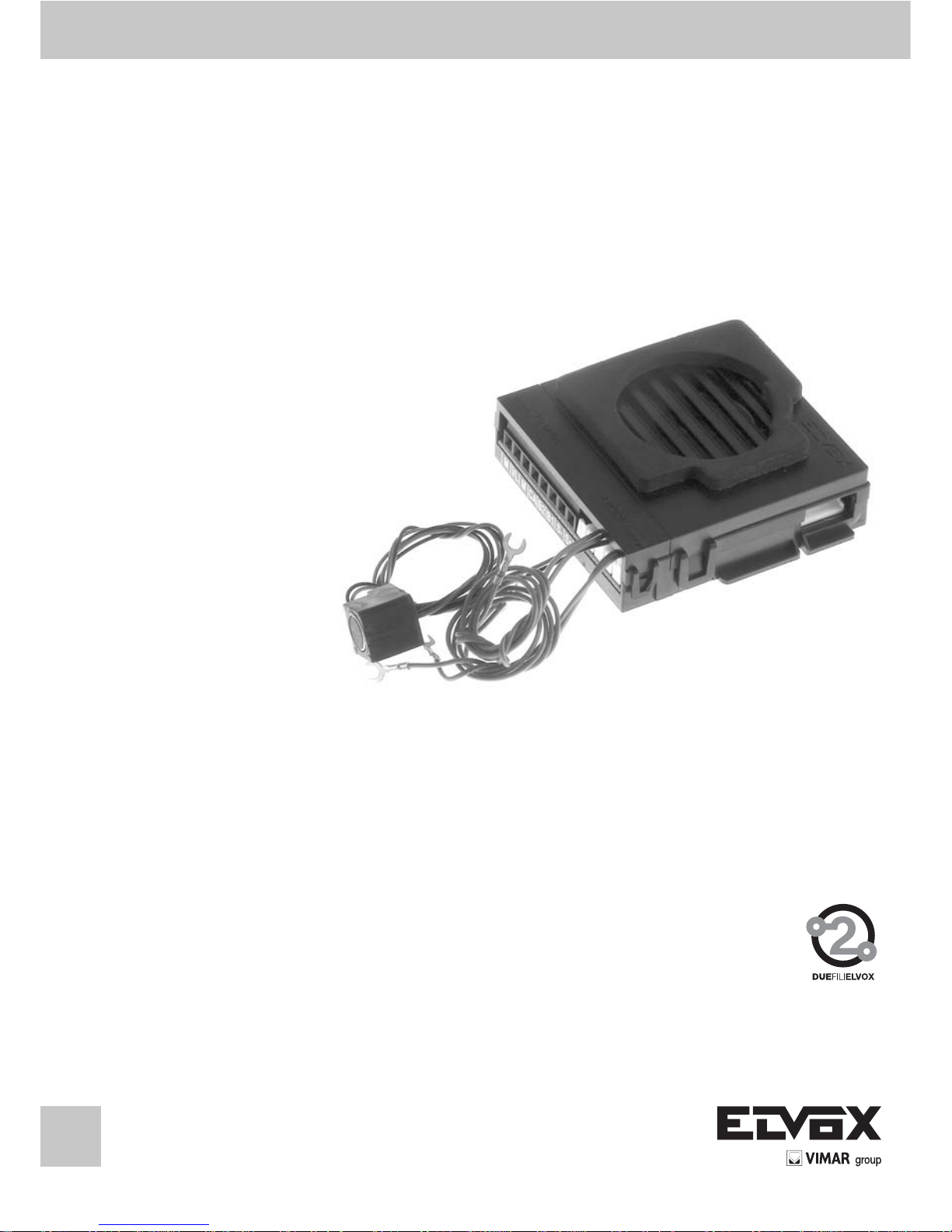
Audio speech unit “Due Fili Elvox”
Page 2

2
GB
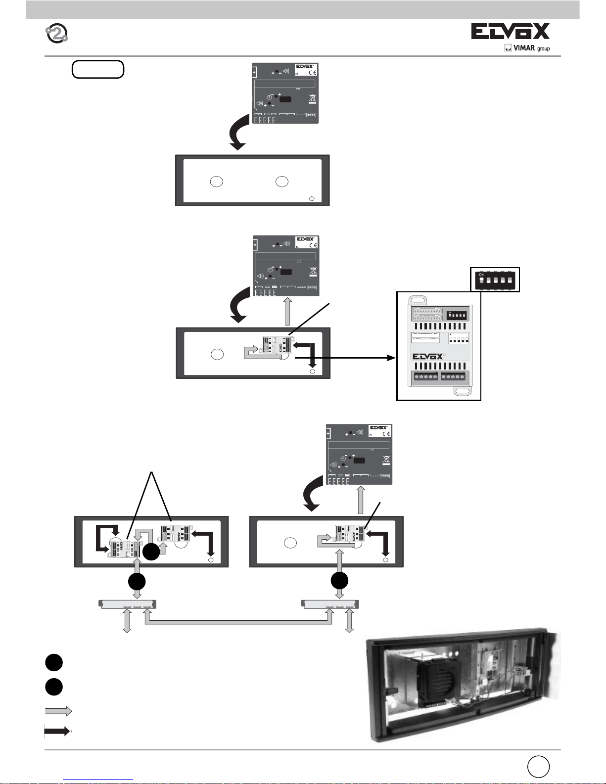
The expansion modules (type 12TS, 12TS/0, 693p, 8051, 8052, 8053,
8054) can be connected to speech unit type 6931 to increase the number of the call push-buttons according to the type of panel.
12TS Additional module with 4 call push-buttons to install in panels
series 1200.
12TS/0 Additional module for connecting 8 push-buttons, applicable
also to entrance panels not belonging to the Elvox series.
693P Addition module with reduced dimensions: 48x70x19 mm (W
x H x D), to be applied also to non ELVOX entrance panels.
8054 (8051, 8052, 8053) additional modules with 4, 1, 2, 3 call
push-buttons with plates, for entrance panels series 8000.
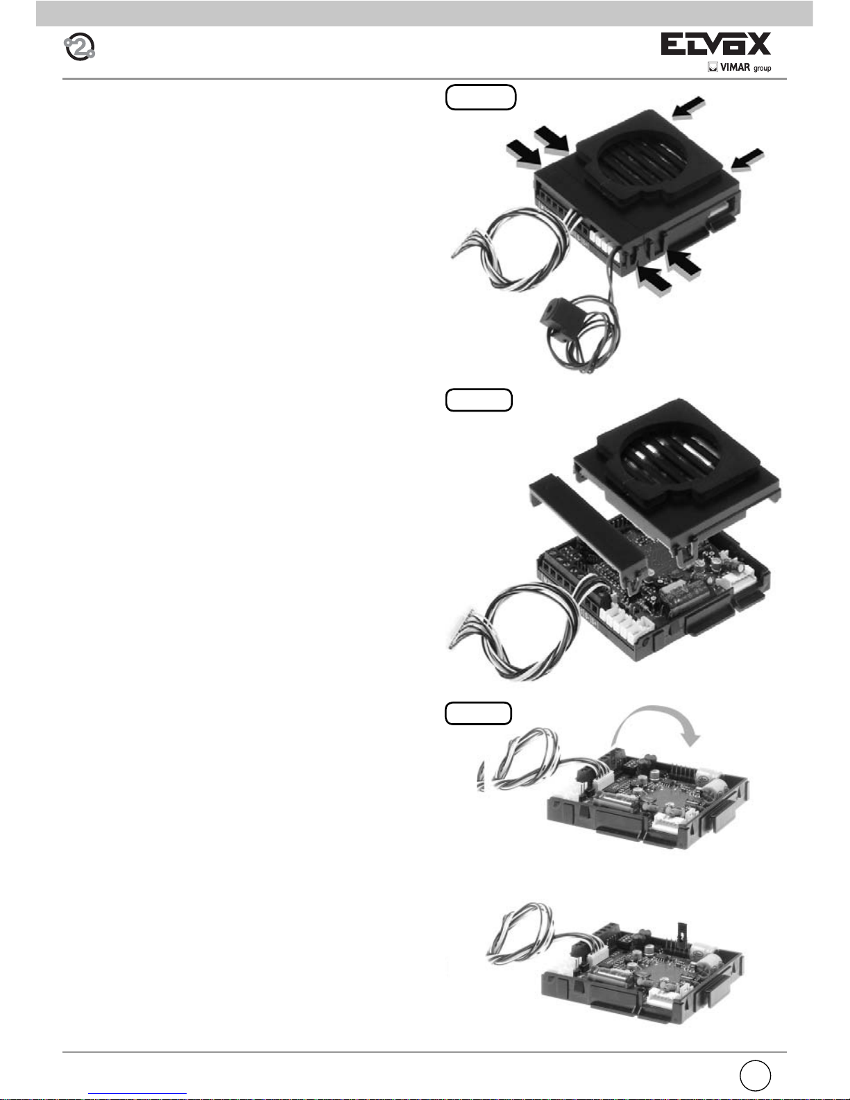
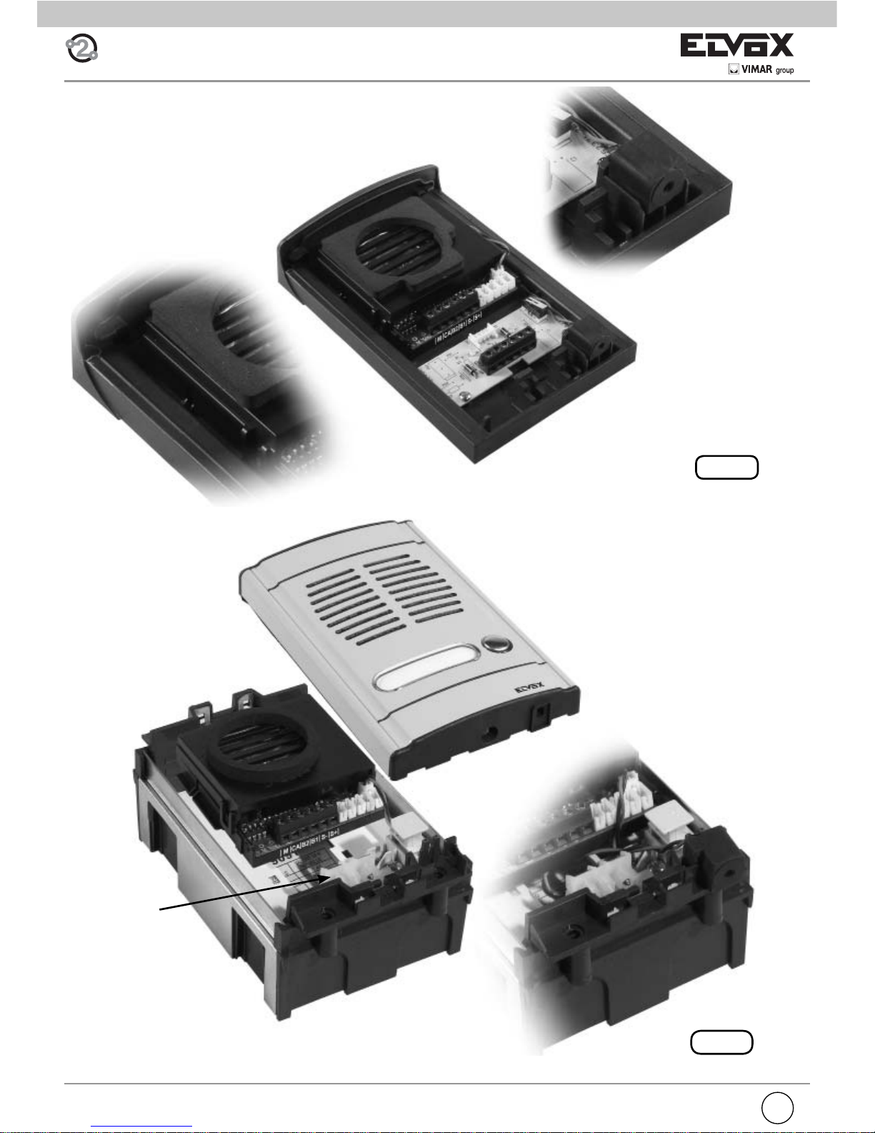
Cable for additional
push-button modules to
CN10
Cable for “Engaged – Please
wait” to C3.3
(Two coloured wires: one red
and one black)
Cable for two push-buttons
to C 3.4 - CH1
to C 3.2 - CH2
((Two coloured green wires)
Cable for name-tag lighting
a C3.6 - Name-tag led
(Two coloured wires: one
green and one black)
Microphone
C3.2 - C3.4
Bracket with fi xing
screws for speech unit
GENERAL INFORMATION
Article 6931 is a speech unit for DUE FILI ELVOX “ELVOX TWOWIRE” audio door entry systems. Article 6931 can manage up to 200
calls and can be used as a Master speech unit, making it possible to
create audio door entry systems. In addition, it can co-exist with video
panels in a mixed DUE FILI ELVOX “ELVOX TWO-WIRE” system (interphone/monitor), by using concentrators art. 692C.
It can be installed in entrance panels series:
- 8000
- 8100
- Patavium
- 3300
- Mail boxes (2550/301 and 2550/302)
- 1200 (for more than 2 push-buttons it is necessary to couple one or
more additional plates with push-buttons type 125x).
Speech unit type 6931 is completely equivalent to type 6930. The
only difference is that, in case of connection of camera type 6570,
657C or interface for TVCC camera type 693T it enables a higher distance between the speech unit and the camera (see wiring diagrams
N. SI559, SI560 for the maximum length of wiring).
Type 6931 can be coupled with B/W or colour cameras, or with converter module for external camera type CCTV.
Type 6570 B/W camera without speech unit
Type 657C Colour camera without speech unit
Type 693T Converter module for external B/W or colour camera
(type CCTV) in 4 DIN modules enclosure.
Series of entrance panels
With internal camera
type 6931 + type 6570
type 6931 + type 657C
With external camera
type 6931 + type 693T
8000 YES
by applying
type 8010 + 8020 (for
6570)
type 8010 + 8T20 (for
657C)
YES
8100 NO YES
PATAVIUM NO YES
3300 NO YES
2550/301-302 YES YES
1200 NO YES
Page 3
GB
3
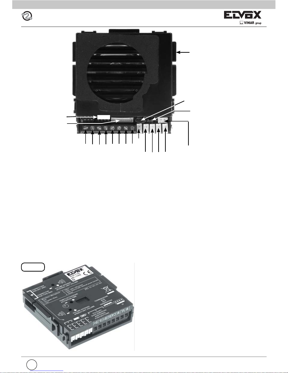
Fig. 1
C3.1 Microphone
Speech unit adjustments
External volume
Speech unit activation time
Internal volume
The settings are printed on the back of the speech unit (see Fig. 1)
M
VL
CN10
C B A
CN9
Connector
for
Art. 950C or
Art. 692I or
Art. 692I/U
M
CA
B2 B1 S-
S+
C3.5 Video
C3.2- CH2
C3.3 Wait/busy
C3.4 - CH1
C3.6 Internal LED power supply
RESET
Speech unit terminals
M VL GROUND
VL POWER SUPPLY OF LEDS FOR SUPPLEMENTARY MODULES
M GROUND
CA DOOR LOCK COMMAND (CONNECT TO “M”)
B2 2-WIRE BUS
B1 2-WIRE BUS
S- LOCK OUTPUT
S+ LOCK OUTPUT
The speech unit gives a current peak IT> 1A for 10 mS after which there follows a holding current IM= 200mA for the entire
duration of the lock command (see lock time).
LED supply
voltage for
additional
modules
C3.2- C3.4
Page 4
4
GB
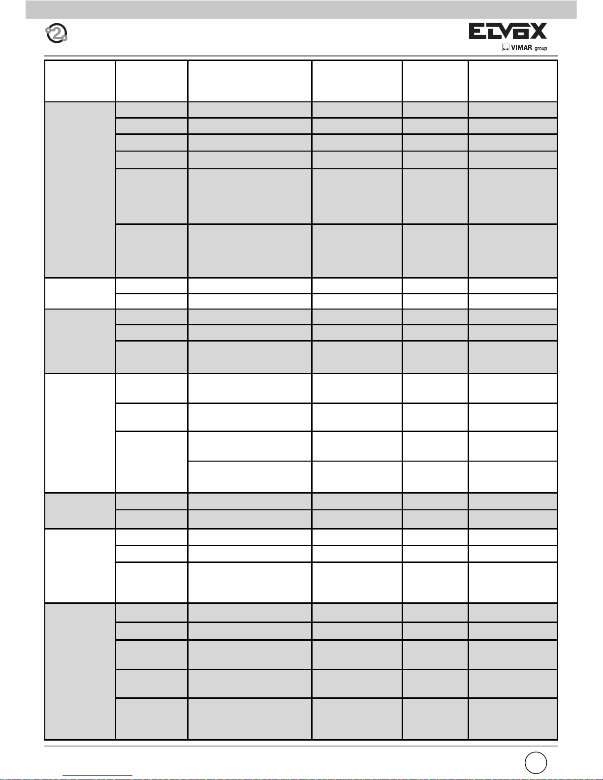
Series of
entrance panels
Number of
push-buttons
Entrance panel type Cables Substitutive
lamp holder
type
Figure
8000
1 88T1 C3.4, C3.6 Fig. 5, page 10
1 8911 C3.4, C3.6 R263 Fig. 6, page 10
2 88T2 C3.2, C3.4, C3.6 Fig. 5, page 10
2 891D C3.2, C3.4, C3.6 R263 Fig. 6, page 10
More than 2
push-buttons
80PA + 8054 (o 8051,
8052, 8053) + module
holder frames, boxes series 8000
CN10, C3.3 Fig. 4B, page 9
More than 2
push-buttons
RPF3 + 8054 (o 8051,
8052, 8053) + module
holder frames, boxes series 8000
CN10 Fig. 4A, page 9
8100
1 8101 C3.4, C3.6 Fig. 8, page 12
2 8102 C3.2, C3.4, C3.6 Fig. 8, page 12
PATAVIUM
1 2101 C3.4, C3.6 Fig. 9, page 12
2 2102 C3.2, C3.4, C3.6 Fig. 9, page 12
More than 2
push-buttons
21xx + 693P C3.6, CN10
3300
1 3301 + Back box Serie
3300
C3.4, C3.6 R261 Fig. 11, page 13
2 3302 + Back box Serie
3300
C3.2, C3.4, C3.6 R261 Fig. 11, page 13
More than 2
push-buttons
3300 + 3958 + Back box
Serie 3300
CN10
330X + 39xx + Back box
Serie 3300
C3.6, CN10
2550/301-302
1 2550/301 C3.4, C3.6 R261 Fig. 10, page 13
2 2550/302 C3.2, C3.4, C3.6 R261 Fig. 10, page 13
1200
1 1200 C3.4, C3.6 R264 Fig. 7, page 11
2 1200 C3.2, C3.6, C3.4 R264 Fig. 7, page 11
1200 with
more than 2
calls
1200 (only for speech unit
Art. 6931) + 125x + 12TS
CN10, C3.6 R264 Fig. 7, page 11
Cabinet
1 25V2* C3.4, C3.6 R264 Fig. 13, page 14
2 25V2 C3.2, C3.4, C3.6 R264 Fig. 13, page 14
Up to 8 push-buttons
25V4 or 25V6 or 25V8,
693P
C3.6 R264 Fig. 13, page 14
Up to 12 push-buttons
25V8, 2508, 2x693P C3.6, C3.10 R264 Fig. 13, page 14
Up to 24 push-buttons
25V8, 2526, 693P,
2x693P
CN10 and cable of
art. 693P and art.
693P/M
R264 Fig. 13, page 14
Page 5
GB
5
C
B
A
Fig. 2
CN9
ON
123
4
ON
123
4
ON
123
4
ON
123
4
ON
123
4
ON
123
4
ON
123
4
ON
123
4
ON
123
4
ON
123
4
ON
123
4
ON
123
4
ON
123
4
ON
123
4
ON
123
4
ON
123
4
1234
DIP SWITCH
ID TARGA
ON
ON
ON ON
ON
ON ON
ON ON
ON ON ON
ON
ON ON
ONON
ON ON ON
ON ON
ON ONON
ON ONON
NON ASSEGNATO
1 (MASTER)
2
3
4
5
6
7
8
9
10
11
12
13
14
15ON ONONON
SOFTWARE CONFIGURATIONS
The software confi gurations can be carried out in two dif-
ferent ways:
- basic confi guration of software
- advanced software confi gurations
INSTALLATION
Assembling and installing the speech unit Art. 6931 requires
the following phases:
- installing the speech unit
- wiring the leads
- installing and wiring any additional modules
- connecting the speech unit to the system
- assigning identifi cation
- programming the speech unit
N.B. Do not connect the bus of the speech unit to the system
until the speech unit wirings have been connected to the
entrance panel.
BUS TERMINATION
On the bottom left side, above the terminal block, there is
the 3-position connector CN9 (Fig. 2). A jumper in one of
the 3 possible positions (A, B, C) enables terminating the
bus correctly as regards the video signal for mixed systems
(audio and video door entry systems). Try out the condition
providing the best vision. If the system is solely an audio
door entry system, insert it in position A.
ASSIGNING
IDENTIFICATION
CN10 ADDITIONAL PUSHBUTTONS ART. 8054
ASSIGNING IDENTIFICATION
The identifi er is assigned with 4 dip switches on the bot-
tom left side above the terminal block (Fig. 2), outside the
enclosure and under the safety lid. The correspondence
between the position of the dip switch and the ID is specifi ed in the following table.
MICROPHONE
ENTRANCE
PANEL ID
NOT ASSIGNED
Page 6
6
GB
Fig. 3A
1
1
2
2
2
Fig. 3B
3
4
2
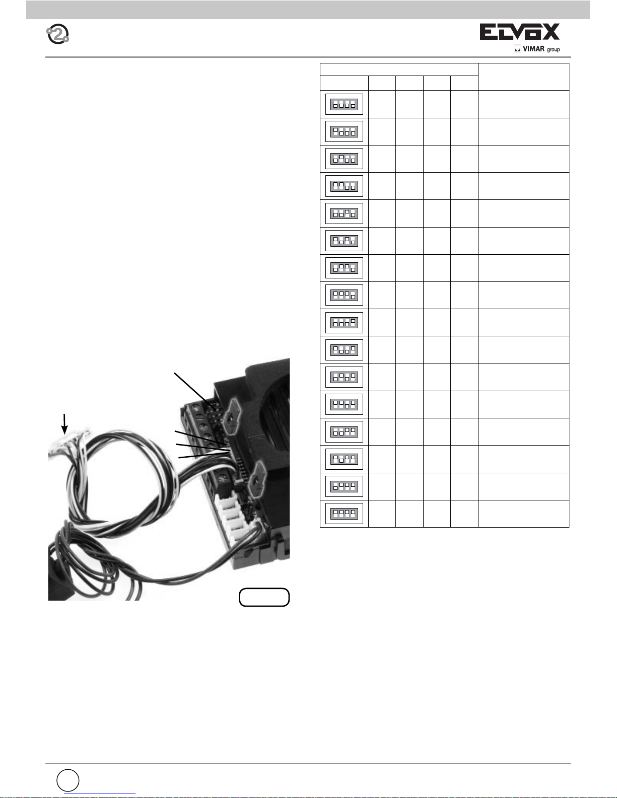
RESETTING PROGRAMS TO THE DEFAULT VALUE
It is possible to bring the programs back to the default value
with a straightforward procedure.
• Open the speech unit by levering on the fastener hooks
(see Fig. 4A).
• Raise the fastener labelled 1 (up arrow).
• Raise the fastener labelled 2 (up arrow).
• Momentarily move the jumper of the termination from CN9
onto terminals 2 and 3 of the programming connector (see
Fig. 4B).
• Momentarily press the reset button RST with the aid, if necessary, of a plastic screwdriver.
DO NOT USE ANY METAL INSTRUMENTS THAT CAN
MECHANICALLY DAMAGE THE ELECTRONIC CIRCUIT OR CREATE SHORT CIRCUITING.
• The speech unit emits a continuous tone for two seconds.
• As the tone is being emitted, press one of the call buttons.
The programs are now reset.
The speech unit restarts by itself. Afterwards put the jumper
back into its original position CN9.
BASIC SOFTWARE CONFIGURATIONS
PUSH-BUTTONS RESET
For the outdoor station it is possible to reset the two push-buttons CH1 and CH2 without using external helps. This can be
done with the following procedure, described for a generic push-button. It is applied either to CH1 either to CH2.
- Remove the terminal block protection cover prizing up on
the closing hooks (see fi g. 3A, arrow 1).
- Raise the hooks indicated with 1 (arrow upward)
- Hold down the RESET push-button using, if necessary, a
plastic screwdriver.
DO NOT USE METALLIC INSTRUMENTS WHICH CAN
DAMAGE MECHANICALLY THE ELECTRONIC CIRCUIT
OR CAUSE SHORT-CIRCUITS.
- Holding down the RESET push-button, keep pressed also
the call push-button to be reprogrammed.
- Hold down the call push-button, release the RESET push-button.
- After two seconds the loudspeaker emits a tone. Simultaneously all the sets with the hook lifted emit a three tone
scale.
- Release the call push-button.
- Press, from the internal unit you want to call with the push-button, one of the push-buttons: lock release, actuator
activation, stair light, F1, F2. Pay attention that if you want
to call a group, this manoeuvre is to be effected by the
leader of the group. You have 25 seconds to carry out this
operation, after that the outdoor station goes back to the
rest mode emitting a tone.
- The outdoor unit confi rms the programming with a tone.
- To return to default programming, instead of acting on the
internal unit, press again the push-button you want to program.
- As an option, verify if the association is correct by pressing
the just programmed push-button and control if the desired
internal unit is called.
- At the end fi t the protection cover again.
Fig. 3C
Page 7
GB
7
ON
123
16
8
4
ON
123
128
64
32
ON
123
16
8
4
ON
123
128
64
32
ON
123
16
8
4
ON
123
128
64
32
ON
123
16
8
4
ON
123
128
64
32
ON
123
16
8
4
ON
123
128
64
32
ON
123
16
8
4
ON
123
128
64
32
ON
123
16
8
4
ON
123
128
64
32
ON
123
16
8
4
ON
123
128
64
32
ON
123
16
8
4
ON
123
128
64
32
ON
123
16
8
4
ON
123
128
64
32
ON
123
16
8
4
ON
123
128
64
32
ON
123
16
8
4
ON
123
128
64
32
ON
123
16
8
4
ON
123
128
64
32
ON
123
16
8
4
ON
123
128
64
32
ON
123
16
8
4
ON
123
128
64
32
ON
123
16
8
4
ON
123
128
64
32
ON
123
16
8
4
ON
123
128
64
32
ON
123
16
8
4
ON
123
128
64
32
Non utilizzare
1 ... 4
5 ... 8
13 ... 16
21 ... 24
29 ... 32
37 ... 40
45 ... 48
53 ... 56
61 ... 64
9 ... 12
17 ... 20
25 ... 28
33 ... 36
41 ... 44
49 ... 52
57 ... 60
65 ... 68
{7 ... 10}
][
{ 3 ... 6 }
][
{11 ... 14}
][
{15 ... 18}][
{19 ... 22}][
{23 ... 26}]
[
{27 ... 30}][
{31 ... 34}]
[
{35 ... 38}]
[
{39 ... 42}
]
[
{43 ... 46}
]
[
{47 ... 50}]
[
{51 ... 54}]
[
{55 ... 57}]
[
{59 ... 62}]
[
{63 ... 66}]
[
{67 ... 70}]
[
ON
123
16
8
4
ON
123
128
64
32
ON
123
16
8
4
ON
123
128
64
32
ON
123
16
8
4
ON
123
128
64
32
ON
123
16
8
4
ON
123
128
64
32
ON
123
16
8
4
ON
123
128
64
32
ON
123
16
8
4
ON
123
128
64
32
ON
123
16
8
4
ON
123
128
64
32
ON
123
16
8
4
ON
123
128
64
32
ON
123
16
8
4
ON
123
128
64
32
ON
123
16
8
4
ON
123
128
64
32
ON
123
16
8
4
ON
123
128
64
32
ON
123
16
8
4
ON
123
128
64
32
69 ... 72
77 ... 80
73 ... 76
81 ... 84
85 ... 88 89 ... 92
93 ... 96 97 ... 100
101 ... 104 105 ... 108
109 ... 112 113 ... 116
{71 ... 74}]
[
{75 ... 78}]
[
{79 ... 82}]
[
{83 ... 86}]
[
{87 ... 90}]
[
{91 ... 94}
]
[
{95 ... 98}]
[
{99 ... 102}]
[
{103 ... 106}]
[ {107... 110}][
{111 ... 114}][
{115 ... 118}]
[
ON
123
16
8
4
ON
123
128
64
32
ON
123
16
8
4
ON
123
128
64
32
ON
123
16
8
4
ON
123
128
64
32
ON
123
16
8
4
ON
123
128
64
32
ON
123
16
8
4
ON
123
128
64
32
ON
123
16
8
4
ON
123
128
64
32
ON
123
16
8
4
ON
123
128
64
32
ON
123
16
8
4
ON
123
128
64
32
ON
123
16
8
4
ON
123
128
64
32
ON
123
16
8
4
ON
123
128
64
32
ON
123
16
8
4
ON
123
128
64
32
ON
123
16
8
4
ON
123
128
64
32
125 ... 128 129 ... 132
133 ... 136
141 ... 144
149 ... 152
157 ... 160
165 ... 168
137 ... 140
145 ... 148
153 ... 156
161 ... 164
169 ... 172
ON
123
16
8
4
ON
123
128
64
32
ON
123
16
8
4
ON
123
128
64
32
117 ... 120 121 ... 124
{119 ... 122}]
[
{123 ... 126}
]
[
{127 ... 130}]
[
{131 ... 134}]
[
{135 ... 138}]
[
{139 ... 142}]
[
{147 ... 150}]
[
{143 ... 146}]
[
{151 ... 154}]
[
{155 ... 157}]
[
{159 ... 162}
]
[
{163 ... 166}
]
[
{167 ... 170}]
[
{171 ... 174}]
[
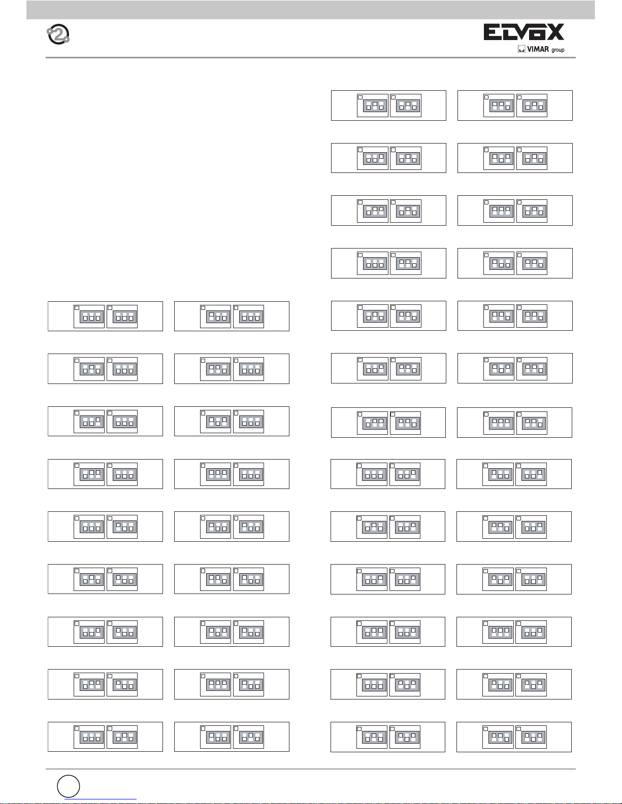
ADDITIONAL MODULE PUSHBUTTON HARDWARE
PROGRAMMING (ART. 8051, 8052, 8053, 8054, 12TS,
12TS/0, 639P)
The dip-switches modify the hardware code of the fi rst pu-
shbutton at the top right of the module, while the other pushbuttons are associated consecutively from top to bottom,
right to left (see Tables 1 and 2). Take care not to overlap the
codes of pushbuttons on the same panel. When using the
modules with pushbuttons in single or double columns the
parameter “Single/Double pushbuttons” must be programmed according to the type of module (see programming).
The confi guration of parameter “single push-buttons”
determines the numbering of push-buttons. If the “single push-buttons” parameter is set to 2 or 3 take into
account the values in [ ] bracket, on the contrary if the
value is set to 0 or 1 take into account the values in {
} bracket.
TABLE 1 - PUSHBUTTONS IN A SINGLE COLUMN
Not to be used
Page 8
8
GB
ON
12
16
8
ON
12
16
8
ON
12
16
8
ON
12
16
8
ON
123
128
64
32
ON
123
128
64
32
ON
123
128
64
32
ON
123
128
64
32
ON
12
16
8
ON
12
16
8
ON
12
16
8
ON
12
16
8
ON
123
128
64
32
ON
123
128
64
32
ON
123
128
64
32
ON
123
128
64
32
ON
12
16
8
ON
12
16
8
ON
12
16
8
ON
12
16
8
ON
123
128
64
32
ON
123
128
64
32
ON
123
128
64
32
ON
123
128
64
32
ON
12
16
8
ON
12
16
8
ON
12
16
8
ON
12
16
8
ON
123
128
64
32
ON
123
128
64
32
ON
123
128
64
32
ON
123
128
64
32
ON
12
16
8
ON
12
16
8
ON
12
16
8
ON
123
128
64
32
ON
123
128
64
32
ON
123
128
64
32
ON
12
16
8
ON
12
16
8
ON
12
16
8
ON
123
128
64
32
ON
123
128
64
32
ON
123
128
64
32
ON
12
16
8
ON
123
128
64
32
ON
12
16
8
ON
123
128
64
32
ON
12
16
8
ON
123
128
64
32
ON
12
16
8
ON
123
128
64
32
Non utilizzare 1 ... 8
9... 16
25 ... 32
41 ... 48
57 ... 64
73 ... 80
89 ... 96
105 ... 112
121 ... 128
137 ... 144
153 ... 160
169 ... 176
17 ... 24
33 ... 40
49 ... 56
65 ... 72
81 ... 88
97 ... 104
113 ... 120
129 ... 136
145 ... 152
161 ... 168
177 ... 184
185 ... 192 193 ... 200
{3 ... 10}]
[
{11 ... 18}
]
[
{19 ... 26}
]
[
{27 ... 34}]
[
{35 ... 42}]
[
{43 ... 50}]
[
{51 ... 58}]
[
{59 ... 66}]
[
{67 ... 74}]
[
{75 ... 82}]
[
{83 ... 90}]
[
{91... 98}]
[
{99 ... 106}
]
[
{107 ... 114}]
[
{115 ... 122}]
[
{123 ... 130}
]
[
{131 ... 138}
]
[
{139 ... 146}]
[
{147 ... 154}]
[
{155 ... 162}]
[
{163 ... 170}]
[
{171 ... 178}]
[
{179 ... 186}
]
[
{187 ... 194}]
[
{195 ... 200}]
[
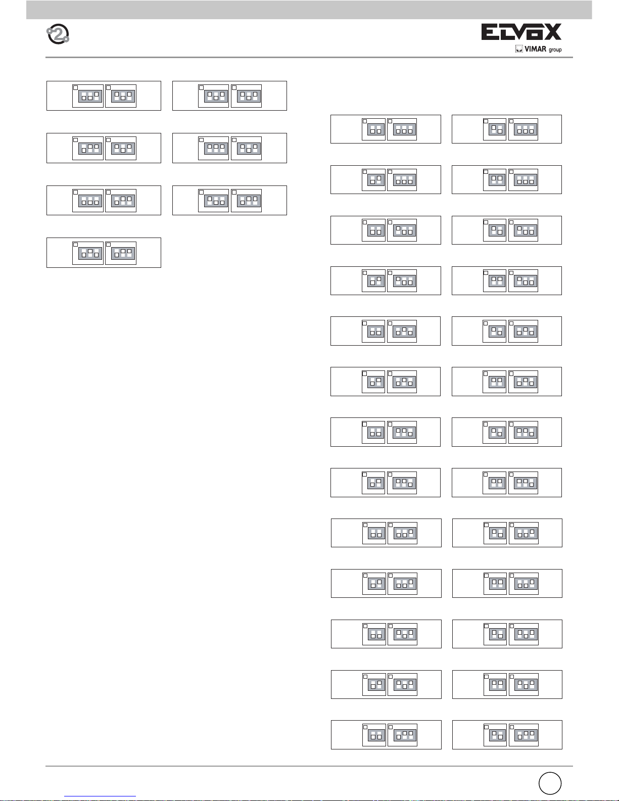
TAB. 2 - PUSH-BUTTONS IN TWO ROWS OR TO BE
USED WITH ADDITIONAL MODULES TYPES 12TS/0
AND 693P
Not to be used
ON
123
16
8
4
ON
123
128
64
32
ON
123
16
8
4
ON
123
128
64
32
ON
123
16
8
4
ON
123
128
64
32
ON
123
16
8
4
ON
123
128
64
32
ON
123
16
8
4
ON
123
128
64
32
ON
123
16
8
4
ON
123
128
64
32
ON
123
16
8
4
ON
123
128
64
32
173 ... 176
181 ... 184
189 ... 192
197 ... 200
177 ... 180
185 ... 188
193 ... 196
{175 ... 178}
]
[
{179 ... 182}
]
[
{183 ... 186}
]
[
{187 ... 190}
]
[
{191 ... 194}
]
[
{195 ... 198}
]
[
{199 ... 200}
]
[
Page 9
GB
9
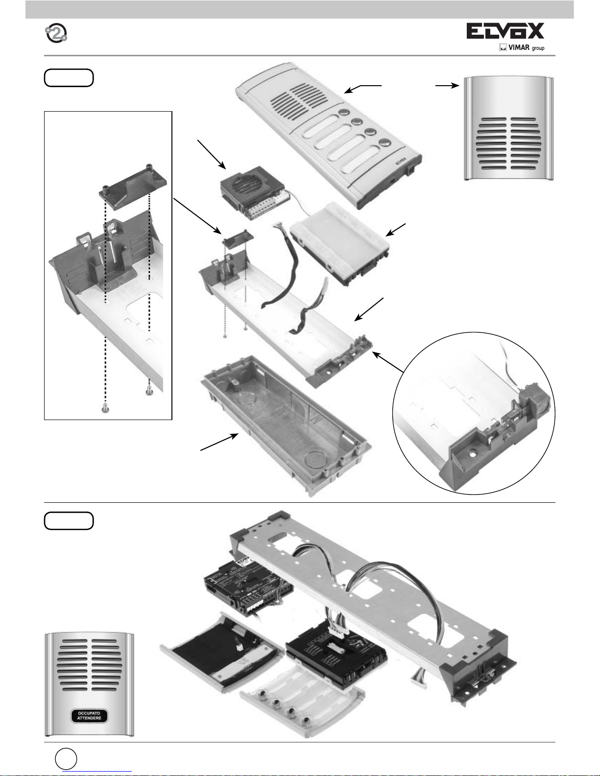
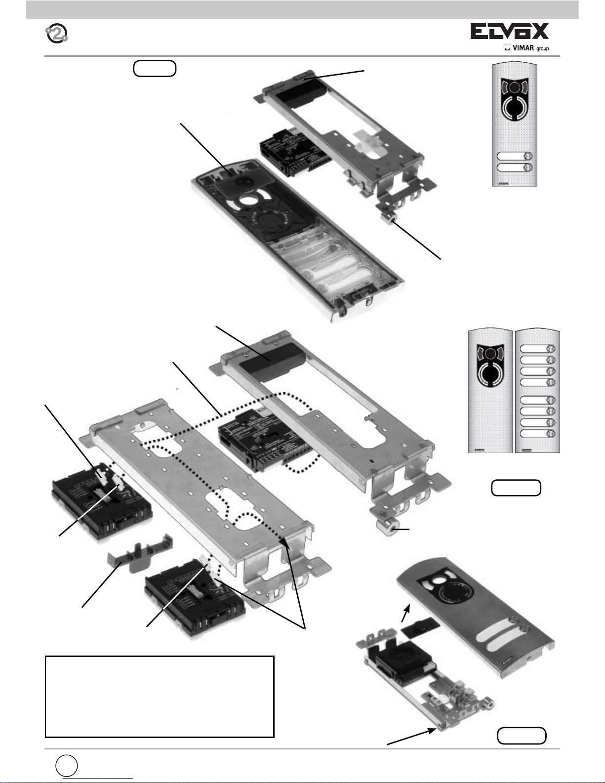
Art. RPF3
Additional module with
push-buttons
Art 6931
Audio speech unit
Art. 9192
Flush-mounted box
Art. RPF3
Microphone
Frame
Bracket with fi xing screws for
speech unit
Fig. 4B
If using the “BUSY - WAIT” signal, use the entrance panel
module 8000 series, Art.
80PA, otherwise Art. RPF3.
Art. 80PA
Fig. 4A
Page 10
10
GB
Fig. 5
Fig. 6
Art. 8911 + ART. R263
Art. 891D + ART. R263
Art. 88T1
Art. 88T2
ART. R263
Page 11
GB
11
Art. 1220
Art. 1258
R693
Fig. 7
Fig. 7A
Art. 1222
Fig. 7B
ART. 264
Cover closing
the lens
Insertion of microphone
type 6931 (see instructions
instructions for entrance panels series 1200)
Bracket with fi xing screws
for speech unit
Bracket with fixing
screws for speech unit
Cable CN10 to module
type 12TS
Cable CN10 from speech
unit type 6931
Additional
module
type 12TS
From module
type 12TS
Other additional
module type 12TS
In a 1200 series entrance panel for a confi gura-
tion with more than 2 push-buttons, speech unit
type 6931 is fi tted in an audio/video plate without
push-buttons type 1220 by coupling one or more
additional plates with push-buttons type 125x for
the installation of additional modules with 4 push-buttons type 12TS.
Insertion of microphone type 6931
(see instructions instructions for entrance panels series 1200)
Page 12
12
GB
Fig. 8
Art. 2101
Art. 2102
Art. 8101
Art. 8102
Fig. 9
Page 13
GB
13
Fig. 10
Art. 2550/301 + ART. R261
Art. 2550/302 + ART. R261
ART. R261
Art. 3301 + ART. R261
Art. 3302 + ART. R261
Fig. 11
ART. R261
Fig. 12
Page 14
14
GB
12345
OK
R
R
ITALY
CN1
CN2
8
16
32
64
128
Art. 693P
ON
12345
OK
R
R
ITALY
CN1
CN2
8
16
32
64
128
Art. 693P
ON
12345
OK
R
R
ITALY
CN1
CN2
8
163264
128
Art. 693P
ON
12345
OK
CONNETTORE
PER ART. 950C
CONNECTOR
FOR TYPE 950C
VOLUME INTERNO
INTERNAL UNIT VOLUME
TEMPO ATTIVAZIONE
ACTIVATION TIME
VOLUME ESTERNO
SPEECH UNIT VOLUME
PULSANTI
SUPPLEMENTARI
ADDITIONAL
PUSH-BUTTONS
A B C
TERMINAZIONE
BUS
BUS
TERMINATION
1
7
ART. / TYPE
6930
ID
4 3 2 1
1 - Microfono / Microphone
2 - CH2
3 - Occupato / Busy
4 - CH1
5 - Video
6 - Alim. LED / LED power
7 - Alim. interna LED / Internal power for LED
8 - Reset
2
3456
R
Made in Italy
DC 28V INT 6W
8
12345
OK
R
R
ITALY
CN1
CN2
8
16
32
64
128
Art. 693P
ON
CONNETTORE
PER ART. 950C
CONNECTOR
FOR TYPE 950C
VOLUME INTERNO
INTERNAL UNIT VOLUME
TEMPO ATTIVAZIONE
ACTIVATION TIME
VOLUME ESTERNO
SPEECH UNIT VOLUME
PULSANTI
SUPPLEMENTARI
ADDITIONAL
PUSH-BUTTONS
A B C
TERMINAZIONE
BUS
BUS
TERMINATION
1
7
ART. / TYPE
6930
ID
4 3 2 1
1 - Microfono / Microphone
2 - CH2
3 - Occupato / Busy
4 - CH1
5 - Video
6 - Alim. LED / LED power
7 - Alim. interna LED / Internal power for LED
8 - Reset
2
3456
R
Made in Italy
DC 28V INT 6W
8
2
2
1
Art. 693P/M
Art. 693P
Art. 6931
Art. 693P
Art. 6931
Art. 6931
Fig. 13
2
1
Long wires supplied with type 693P/M
Short wire supplied with type 693P
Wire supplied by the installer
Wires supplied
back box type 256S
Extensions
(Extensions)
back box type 256S
Page 15

GB
15
ADVANCED SOFTWARE CONFIGURATIONS
The advanced confi gurations can be made via the programmer
Art. 950C or PC Software SaveProg (Art. 69CD) with interface
Art. 692I or Art. 692I/U by connecting it on the right-hand side
of the speech unit (see Fig. 14):
Fig. 14
The button has no function because the programmer is powered via the bus. For the same reason the auto-shutdown function is not available.
The programmer keys and enable selection
of the following item from the main menu:
During the phase of waiting for the response from the speech unit, the display shows:
After a few seconds the programmer display will show the
type and release of the software for the speech unit:
If the speech unit is connected to one of the modules
6570, 657C, 693T, the code 6931 is replaced by 693V.
When it disappears the fi rst item on the programming
menu will appear. The programming procedure ends ei-
ther due to timeout or by pressing the
button while
you are in any of the external menus listed below.
MESSAGE LANGUAGE
The programs can be run in Italian (local language, default) or in English. To change language, press
for
Italian or
for English.
To cancel press . To confi rm, press . Accep-
tance of the command, as in all cases, is shown on the
fi rst line of the display:
The display now changes to:
By pressing you move onto the previous item of the
programming menu.
The programmer keypad layout is as follows:
SOFTWARE CONFIGURATIONS WITH PROGRAMMER
Page 16
16
GB
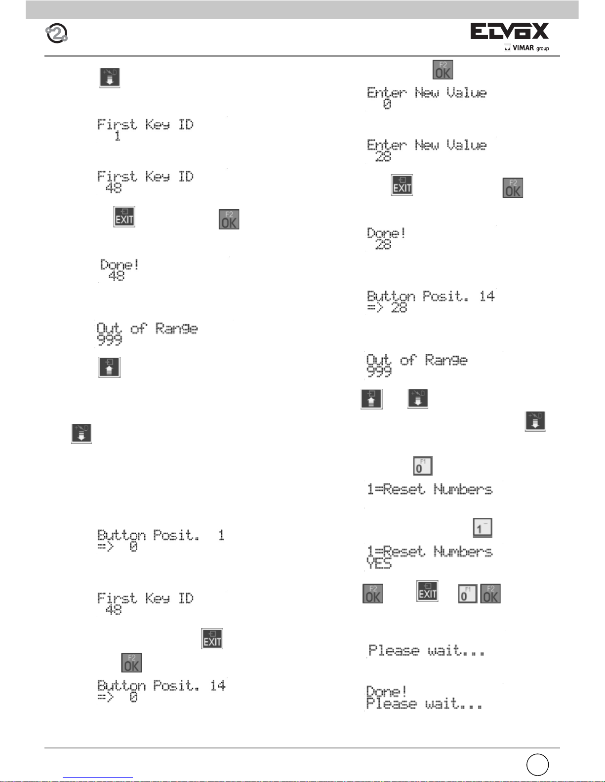
To change mapping, press :
enter a number between 1 and 200.
To cancel press . To confi rm, press . Accep-
tance of the command, as in all cases, is shown on the fi rst
line of the display:
Afterwards you go back to see the new programming value
and you can continue with another pushbutton:
If the ID is outside the limit, the fi rst line of the display will
signal the incongruity:
Use keys and to move from one pushbutton to
another. From the position of pushbutton 1, press
. to
move to the next item in the programming menu. To cancel
all the remapping, instead of pressing a pushbutton or ente-
ring the number, press
:
You are asked to confi rm by pressing :
and then
Press or to cancel the
procedure. If remapping reset is selected, the following is
displayed:
And at the end:
FIRST BUTTON ID
Press button
to move to the next item by which you can
change the number of the audio/video door entry unit called in
correspondence with the pushbutton CH1 of the speech unit.
To change the ID, enter a number between 1 and 200.
To cancel press . To confi rm, press . Acceptance
of the command, as in all cases, is shown on the fi rst line of
the display
:
If the ID is outside the limit, the fi rst line of the display will
signal the incongruity:
By pressing you move onto the previous item of the
programming menu.
REMAPPING PUSHBUTTONS (HARDWARE / SOFTWARE
CONVERSION)
Press
to move to the next item by which you can change
the number of the mointor called in correspondence with any
pushbutton of the speech unit. When programmed accordingly, the user can set the system so that several pushbuttons
call the same intephone/ monitor. By default each pushbutton
calls the intephone/ monitor door entry unit corresponding to
the physical position on the keypad. This is indicated by the
value 0 on the conversion table:
To change the pushbutton to resign, press it directly or key in
the digits so as to form a number between 1 and 200.
In the second case, to cancel press . To confi rm the
pushbutton, press
.
Page 17
GB
17
Press to pass quickly, skipping all the intermediate
steps, onto the previous item of the programming menu.
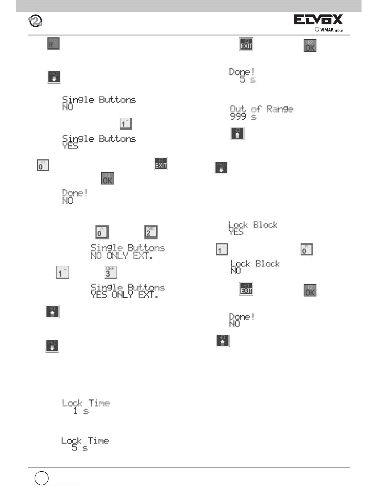
SINGLE PUSHBUTTONS
Press
to move to the next item by which you can cho-
ose from the pushbuttons on one (default) or two columns.
To change the confi guration, press
for a single column:
or
for a double column. To cancel press . Pro-
gramming is confi rmed with
:
As push-button number extension you can choose the use of
only external push-buttons, either in single either in double
row. To do this instead of
you can use .
instead of
you can use .
Press
to move to the previous item of the programming
menu.
LOCK TIME
Press
to move to the next item by which you can change
the time for which the lock is activated whether controlled by
intephone/ monitor or locally via the AC terminal of the terminal block.
When controlled by an intephone/ monitor, the Lock Block
described below is observed.
What is shown corresponds to the current value:
By keying in the digits, the time can be changed in steps of
one second:
To cancel press . To confi rm, press . Acceptance
of the command, as in all cases, is shown on the fi rst line of
the display
If the time is outside the limit, that is longer than 5 seconds,
the fi rst line of the display will signal the incongruity:
By pressing you move onto the previous item of the
programming menu.
LOCK BLOCK
Press
to move to the next item by which you can activate or deactivate (default) the lock command block by an
intephone/ monitor. When the block is inserted, the door lock
can be activated only if the interphone/video interphone is
called by the speech unit, or in conversation with it or it has
self inserted.
The current value is shown on display:
Press
to activate the block, press to eliminate it:
To cancel press
. To confi rm, press . Acceptance
of the command, as in all cases, is shown on the fi rst line of
the display
Press to move onto the previous item of the programming menu.
Page 18
18
GB
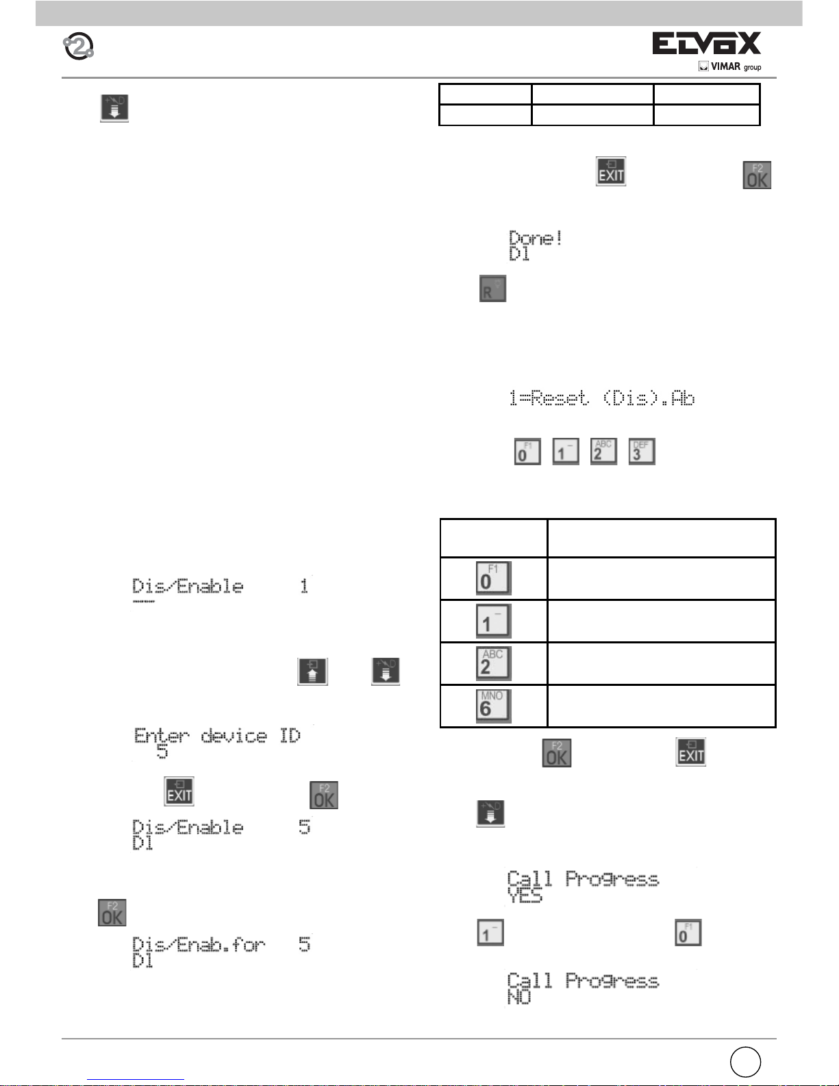
ENABLING / DISABLING
Press
to move to the next item by which, for each device, you can program controls on some commands that the
speech unit receives.
It is possible to confi gure one or more speech units so they do
not react, for one or more intephone/ monitor, on activating
the lock that would derive from the programming described in
the single paragraphs.
On the contrary, it is possible to program the speech unit so
as to permit activation only by some intephone/ monitor. To
run the minimum number of programs, if the speech unit has
at least one programmed common lock, the items function
as enabling signals. If no settings are entered, the items function as disable selections. Given that the common locks are
usually used in locations such as building complexes, less
settings may be made by programming one common lock and
enabling only the users of the relative stairway.
For example a main speech unit (the outermost one) calls 4
monitors in one building and 1 in an annex. The building has
in its turn a speech unit at the bottom of the stairway that calls
the only 4 monitors in the building. The speech unit at the
bottom of the stairway must be programmed with the lock in
common with the main one so that when the lock of the main
speech unit is operated the one at the bottom of the stairway
is governed as well to create a prearranged route. The annex
is also called from the main speech unit, but if the lock is activated, the stairway lock does not react because access to the
annex is via a separate path. To obtain this condition, only the
IDs of the video door entry units in the same stairway should
be selected on the speech unit at the bottom of the stairway so
as to avoid activation of the lock by the monitor in the annex.
There is no disable selection by default. The lack of disable
selection is indicated by “—“. To change the ID of the audio /
video door entry unit press buttons and .
Otherwise, enter the number of the audio / video door entry
unit, from 1 to 200:
To cancel, press . To confi rm, press .
To modify disable selections of the selected audio / video door
entry unit, starting from where the current value is shown,
press
.
The correspondence between disable selections, symbols
and keys is as follows:
Press one key alternately to add / remove the corresponding
function. To cancel, press
. To confi rm, press .
Acceptance of the command, as in all cases, is shown on the
fi rst line of the display:
Press
to move quickly, skipping all the intermediate
steps, to the previous item of the programming menu.
To change the settings of all the audio/video door entry units,
the procedure is as follows. For the ID key in no. 0. The
display shows :
Use buttons , , , to select what to do,
that is whether to engage or release the lock for all. The following table shows the actions.
PUSH-BUTTON ACTION
Do not do anything
Deselect De (for compatibillty)
Deselect De
Select De
To confi rm, press
. To cancel press .
SOUND IN THE SPEECH UNIT
Press
to move to the next item by which you can activate (default) or deactivate the call control tone in the speech
unit. The current value is shown on display:
Press
to activate the sound, press to eliminate
it:
OBSTACLE ABBREVIATION PUSH-BUTTON
Door lock De 1
Page 19

GB
19
To cancel press . To confi rm, press . Acceptance
of the command, as in all cases, is shown on the fi rst line of the
display:
Press to move onto the previous item of the programming menu.
RINGTONE CYCLE NUMBER
Press
to move to the next item by which you can change
the number of call cycles emitted by the speech unit. Each
ringtone cycle follows the rhythm of 1 s ringtone and 2 s pause,
which means each cycle lasts 3 s. What is shown corresponds
to the current value:
By keying in the digits, the number of cycles can be changed:
To cancel press . To confi rm, press . Acceptance
of the command, as in all cases, is shown on the fi rst line of the
display:
Press to move onto the previous item of the programming menu.
CONTROLLER PUSHBUTTON
Press
to move to the next item by which you can program which pushbuttons may be associated with the call of one
of the four porter’s lodge controllers contemplated in the
ELVOX 2-WIRE system.
By default there is no assignment:
Enter a number between 1 and 200:
To cancel, press . To confi rm, press . Acceptance
of the command, as in all cases, is shown on the fi rst line of the
display:
If the ID is outside the limit, the fi rst line of the display will
signal the incongruity:
To cancel the assignment, enter 0 for the ID.
It is possible to move from one pushbutton to another also by
using
and . From the position of pushbutton 1,
press
to move to the next item of the programming
menu.
Press
to move quickly, skipping all the intermediate
steps, to the previous item of the programming menu.
COMMON LOCKS
Press
to move to the next item by which you can program for which other lock operations the current speech unit
must activate its output. In practice the lock output of a speech unit can be activated not only by a direct command, but
indirectly because the lock of another speech unit (at most
another four) has been commanded. It is clear that in this
case any Lock Block is not respected. By default there is no
assignment:
Enter a number between 1 and 15, i.e. the ID of an entrance
panel (in this case the fi rst of four possible choices) for con-
trolling whose lock also the current speech unit must activate
its own:
To cancel, press . To confi rm, press . Accep-
tance of the command, as in all cases, is shown on the fi rst
line of the display:
If the ID is outside the limit, the fi rst line of the display will
signal the incongruity:
To cancel the assignment, enter 0 for the ID.
It is possible to move from one index to another also by using
and .From position 1, press to move to
the next item of the programming menu. Press
to move
quickly, skipping all the intermediate steps, to the previous
item of the programming menu.
Page 20
20
GB
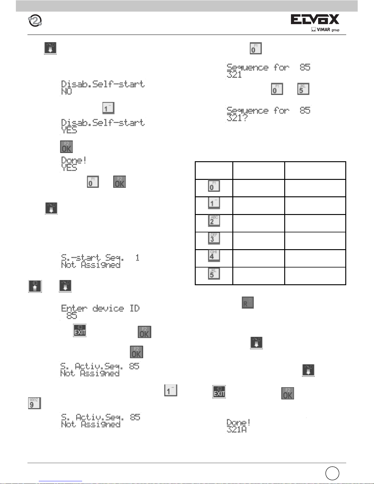
SELF-INSERTION / SELF-START DISABLING
Press
to move to the next item by which the main speech
unit can be confi gured so as not to perform the self-insertion /
self-start function at the system level. By default the function
is on, do disabling is NO:
To activate the setting, press :
Followed by :
To deactivate it, press and .
SELF-INSERTION / SELF-START SEQUENCE
Press
to move to the next item by which you can program the self-insertion / self-start sequence of the speech
units, interphone by interphone. By default there is no sequence and so only the MASTER speech unit is used. The item
appears only if the programmer is connected to a MASTER
speech unit, otherwise you move to the next function.
To change the ID of the interphone/monitor press buttons
and . Otherwise, enter the number of the inter-
phone/monitor, from 1 to 200:
To cancel, press . To confi rm, press . To change
the sequence of the selected interphone/monitor, starting from
where the current value is shown, press
.
To specify the sequence of entrance panels, use the ..
buttons for the fi rst 9 entrance panels.
For panels with ID greater than 9, a prefi x mechanism is used
with the aid of button
. Press it a fi rst time, in place of a
digit the ‘?’ symbol appears
Now, press a button between and so as to form
the ID between 10 and 15
.
Given that only one location is used on the display to show
these values, the letters A to F are used, according to the
following table:
The last ID present in the sequence can be cancelled by
means of the key
. IDs may be duplicated within a sequence. The maximum limit is 15 per interphone/monitor.
To help compose equal sequences, for this programming
there is the concept of “notebook” or “clipboard”. During editing mode, and when there is no ‘?’ symbol displayed, if the
user presses the key
, the sequence shown on display
is copied into a temporary memory zone.
The user can terminate the current sequence, by moving to
another interphone/monitor and pressing
, thus recal-
ling this memory which replaces the one present. To cancel
press
To confi rm, press . Acceptance of the
command, as in all cases, is shown on the fi rst line of the
display:
BUTTON ID LETTER LETTER
10 A
11 B
12 C
13 D
14 E
15 F
Page 21

GB
21
It is possible to move from one ID to another also by using
and . From the position of ID 1, press to
move to the next item in the programming menu. To cancel all
the sequences, starting from where the current value is
shown, press
:
You are asked to confi rm by pressing :
and then . Press or to cancel the procedure. If you choose to reset the sequences, the display
shows:
And at the end:
Press to move quickly, skipping all the intermediate
steps, to the previous item of the programming menu.
CHANGING MONITOR/INTERPHONE CONFIGURATION
For each audio and video door entry unit installed in the system, it is possible to confi gure operating functions grouped
in four zones “Flag”, “Programmable buttons”, “Call groups”,
“Door call”. The audio/video door entry units in the 6600 series have a fi fth zone composed of the audio/video levels. To
execute this procedure, the devices to be programmed (interphones and monitors) have to be connected to the system
and have to be identifi ed with a code.
The entrance panel searches for the fi rst device (interphone
and monitor), identifi ed with the physical code 1, and analy-
ses the type of associated device (6209, 6209+6009, 6309,
6601, etc.).
Use the push-buttons and to select one of the
200 devices. If applicable, key in the code of the device and
press
to select it.
Next to the desired device, press
to access change
mode. The confi guration options change according to the
type of device as indicated in the following diagrams.
Once in confi guration mode, use the push-buttons
,
and to move between parameters, the push-but-
ton
to confi rm changes, and the push-button to
cancel changes. The 1st line of the display shows the current
parameter and the 2nd shows the value assigned to it.
Page 22

22
GB
CLASS MEANING 6209 (+ 6009) 6309
FLAG PROGRAMMING
YES = the monitor switches on when a
panel call is made (except for 6209)
YES = the green led is managed as door
open indicator
YES = the lock pushbutton is used by the
device
NO = the pushbutton is used externally
(only for 6309/P, 6309/CP)
YES = the stair light pushbutton is used by
the device
NO = the pushbutton is used externally
(only for 6309/P, 6309/CP)
SI = il pulsante auto accensione è utilizzato
dal dispositivo
NO = è utilizzato esternamente (solo per
6309/P, 6309/CP)
YES = if the F1 / F2 pushbutton is programmed directly on a specifi c panel, only
panels 1 to 8 can be programmed
NO = only panels 9 to 15
YES = the device is working in porter switchboard mode
YES = the device sends the lock command
automatically when a external speech unit/
panel calls, if P6 is closed
YES = group G3 functions only for external
calls
YES = group G4 functions only for internal
calls
YES = eliminates the click sound when a
valid key is pressed
YES = does not activate the call repeated
output for intercommunicating calls
YES = group G1 functions only for external
calls
YES = group G2 functions only for internal
calls
YES = the monitor / interphone does not
ring for intercommunicating calls
YES = the monitor / interphone does not
ring for calls from panels
Page 23

GB
23
CLASS MEANING 6209 (+ 6009) 6309
FLAG PROGRAMMING
YES = After the automatic door lock activation because of the Serr. Aut. fl ag with P6 close the
interphone or the video interphone cancels the call.
[NO] The possible automatic door lock does not
make the call end (default).
Usually used for a group master.
YES = the call is accepted, and then the secondary
units ring, even if the group master has ringtone off
and therefore does not ring.
NO = if a group master turns off the ringtone none
rings and there is a warning on the entrance panel.
YES = the device has no timeout for the intercommunicating conversation. For it to work properly, both parties
talking to each other must have it on YES.
NO = (Default) and the intercommunicating conversation lasts at most 5 minutes.
YES = If it is programmed for a head group, this
latter, at the call reception from the push-button
module type 6120, will inform the other members
that it is ringing. If it is programmed for the group
members, they will answer at the call from a type
6120 to their head group ringing. In this way it is
possible to divide the calls between external,
internal and outdoor calls.
NO = No reaction.
CLASS MEANING 6209 (+ 6009) 6309
PROGRAMMABLE KEYS
P0 is lock push-button
Functions assigned to pushbuttons.
P1, P2, P3, P7 and P8 as default
(i.e. not programmed) take the
specifi ed value
GROUPS
First call group programming
Fourth and last call group programming
DOOR CALL
First door call
Fourth door call
Page 24

24
GB
CLASS MEANING 6601 6611 8879
FLAG PROGRAMMING
YES = the monitor switches on when a panel
call is made (not for /AU)
YES = the green led is managed
as door open indicator
YES = if the F1 / F2 pushbutton is programmed
directly on a specifi c panel, only panels 1 to 8 can
be programmed
NO = only panels 9 to 15
YES = the device is working in porter switchboard
mode
YES = group G3 functions only for external calls
YES = group G4 functions only for internal calls
YES = eliminates the click sound when a valid key
is pressed
YES = does not activate the call repeater output for
intercommunicating calls
YES = group G1 functions only for external calls
YES = group G2 functions only for internal calls
YES = the monitor / interphone does not ring for
intercommunicating calls
YES = the monitor / interphone dos not ring for calls
from panels
YES = pressing the door lock push-button ends the
conversation (default value in model /F of monitor)
NO = the door lock push-button operates normally
YES = to activate the audio connection press
the talk/listen push-button. To deactivate the audio
press the push-button again (default value on
model /F of monitor).
NO = To activate the audio connection the talk/
listen push-button must be kept pressed.
Valid only for some Vimar products.
YES = the square button (self-start) becomes the
second function regardless of the position of the
mechanical switch.
NO = has the self-start function.
Valid only for some Vimar products.
YES = there is home automation.
NO = (Default)
Page 25

GB
25
CLASS MEANING 6601 6611 8879
PROGRAMMAZIONI FLAG
Usually used for a group master.
YES = the call is accepted, and then the secondary
units ring, even if the group master has ringtone off
and therefore does not ring.
NO = if a group master turns off the ringtone none
rings and there is a warning on the entrance panel.
YES = the device has no timeout for the intercommunicating conversation. For it to work properly, both
parties talking to each other must have it on YES.
NO = (Default) and the intercommunicating conversation lasts at most 5 minutes.
YES = After the panel ring tones the monitor answers
automatically. Even the fl ag “T./L. On/Off:NO” must
be set to YES.
NO = No automatic answer (default).
YES = If it is programmed for a head group, this latter, at the call reception from the push-button module
type 6120, will inform the other members that it is
ringing. If it is programmed for the group members,
they will answer at the call from a type 6120 to their
head group ringing. In this way it is possible to divide
the calls between external, internal and outdoor calls.
NO = No reaction.
Page 26

26
GB
CLASS MEANING 6601 6611 8879
PROGRAMMABLE KEYS
Functions assigned to pushbuttons.
P0, P1, P2, P3, P7 and P8 as default
(i.e. not programmed) take the specifi ed value
GROUPS
First call group programming
Fourth and last call group programming
DOOR CALL
First door call
Fourth door call
LEVELS
Ringtone volume
Hands free volume
Ringtone type
Monitor brightness (not /AU)
Monitor contrast (not /AU)
Number of ringtone for door call (only
for some Vimar products)
Number of ringtone for intercommunicating call
(only for some Vimar products)
Page 27

GB
27
- FLAG PROGRAMMING
Next to the desired FLAG, press 1 for YES and 0 for NO.
Press
to confi rm the change. When you confi rm the
change, the message “Done!” will appear.
FLAG description
Monitor Switch-on -> [YES] The monitor switches on
when called by the entrance panel
(default).
[NO] The monitor does not switch on
when called, but can switch on with
the self-start function or by replying.
Green LED -> [YES] The green LED is used to indi-
cate that the door is open (default).
[NO] The LED remains OFF.
Lock -> [YES] The lock push-button is set to
open the door (default).
[NO] The lock push-button is used
as an N.O. push-button with free
contacts, for types 6309/P and
6309/CP only.
Stair light -> [YES] The stair light push-button is
set to activate the 1st auxiliary fun-
ction of the 1st relay (default).
[NO] The stair light push-button is
used as an N.O. push-button with
free contacts, for types 6309/P and
6309/CP only.
Self-start -> [YES] The self-start push-button is
set for self-start of the monitor (de-
fault).
[NO] The self-start push-button is
used as an N.O. push-button with
free contacts, for types 6309/P and
6309/CP only.
F1/F2 1-8 -> [YES] If a push-button is program-
med for direct F1/F2 to a specifi c
entrance panel, the push-button can
manage F1/F2 of entrance panels 1
to 8 (default).
[NO] If a push-button is program-
med for direct F1/F2 to a specifi c
entrance panel, the push-button can
manage F1/F2 of entrance panels 9
to 15 (default).
Switchboard -> [YES] The device works in a system
with switchboard.
[NO] The device does not work in a
system with switchboard (default).
Auto. Lock ->
[YES] The device sends the door lock
release command on receipt of a call
from the entrance panel if push-button
P6 is closed.
[NO] The device does nothing (de-
fault).
G3 ext. only -> [YES] The call group G3 is made
only for calls from an entrance
panel.
[NO] The call group G3 is made for
intercommunicating calls and calls
from an entrance panel (default).
G4 int. only -> [YES] The call group G4 is made
only for intercommunicating calls.
[NO] The call group G4 is made for
intercommunicating calls and calls
from an entrance panel (default).
No beep -> [YES] When a push-button is pres-
sed on the interphone/monitor a
beep is emitted (default).
[NO] When a push-button is pres-
sed on the interphone/monitor no
beep is emitted.
No CALLREP IC -> [
[YES]
Does not activate the call
repeater output for the intercommunicating calls
[NO] Activates the call repeater
output for the intercommunicating
calls (default).
G1 only ext ->
[YES]
The G1 call group is carried
out only for calls from entrance
panel
[NO] The G1 call group is carried
out for call from entrance panel
and intercommunicating units (default).
G2 only ext ->
[YES]
The G2 call group is carried
out only for intercommunicating
calls
[NO] The G2 call group is carried
out for call from entrance panel
and intercommunicating units (default).
No int. ring ->
[YES]
Monitor/Interphone does
not sound for intercommunicating
calls.
[NO] Monitor/Interphone sounds
for intercommunicating calls (default).
No ext. ring -> [
[YES]
Monitor/Interphone does not
sound for call from entrance panel.
[NO] Monitor interphone sounds for
call from entrance panel (default).
Para 6209
Door lock Terminates->
[YES]
Pressing the lock push-button terminates the conversation
(default in model /F of monitor).
[NO] The lock push-button opera-
tes normally from version 4 of monitor and entrance panels
Page 28

28
GB
V.V. On/Off -> [YES] To activate the audio line
press the push-button talk/listen. To
deactivate the audio line press the
push-button again (default in model
/F of monitor).
[NO] The talk/listen push-button must
be hold down to activate the audio
line. From version 4 of monitor and
entrance panels.
Fine Ser.aut -> [YES] After the automatic door lock
activation because of the Serr. Aut.
fl ag with P6 close the interphone or
the video interphone cancels the call.
[NO] The possible automatic door
lock does not make the call end (de-
fault).
Force 2nd F. -> Valid only for some Vimar products.
[YES] the square button (self-start)
becomes the second function regar-
dless of the position
of the mechanical switch.
[NO] has the self-start function.
VIMAR Home A. -> Valid only for some Vimar products.
[YES] there is home automation.
[NO] (Default)
ACK Ring Exc. -> Valid for all, except 8879. Usually
used for a group master.
[YES] the call is accepted, and then
the secondary units ring, even if the
group master has ringtone off and
therefore does not ring.
[NO] if a group master turns off the
ringtone none rings and there is a
warning on the entrance panel.
I. C. unlimit. -> [YES] the device has no timeout for
the intercommunicating conversa-
tion. For it to work properly, both par-
ties talking to each other must have
it on YES.
[NO] (Default) and the intercommuni-
cating conversation lasts at most 5
minutes.
Autom. Answer -> [YES] After the panel ring tones the
monitor answers automatically. Even
the fl ag must be set to YES V.V. ON/
OFF.
[NO] No automatic answer (default).
Group F.P. -> [YES] If it is programmed for a head
group, this latter, at the call reception
from the push-button module type
6120, will inform the other members
that it is ringing. If it is programmed
for the Mgroup members, they will
answer at the call from a type 6120
to their head group ringing. In this
way it is possible to divide the calls
between external, internal and out-
door calls.
[NO] No reaction.
- PROGRAMMABLE KEY PROGRAMMING
Next to the desired push-button (P1 to P8), press to ac-
cess change mode. Press
to exit change mode. Select
one of the following 8 functions to assign to the push-button by
means of the push-buttons
and .
N.B.: Even if indicated in the table, the push-buttons may not
be operative, depending on the version of the device.
- Default value
Assigns the default value to the pushbutton.
Default values:
P0=Lock P1=Self-start
P2=Stair light P3=Auxiliary 2
P4=Not assigned P5=Not assigned
P6=Not assigned P7=F1
P8=F2
FUNCTION DESCRIPTION
The key takes on the default value. For buttons
P0, P1, P2, P3, P7 and P8
the default is a function,
indicated in the preceding
table.
The button makes an intercommunicating call
The button turns on a
specifi c speech unit
The button turns on one
of the relays Art. 692R
and 69RH
The button turns on the
output F1 of the entrance
panel in conversation or
anyhow the last one used
The button turns on the
output F2 of the entrance
panel in conversation or
anyhow the last one used
The button turns on the
output F1 of a specifi c
entrance panel
The button turns on the
output F2 of a specifi c
entrance panel
The button switches over
the ringtone mute function for intercommunicating calls
The button switches
over the ringtone mute
function for calls from a
speech unit
Page 29

GB
29
Type 6209
P2
P0
P2
P1
P8
P6
P7
P5
P4
P3
P0
Type 8879
DESCRIPTION OF AUDIO/VIDEO DOOR ENTRY UNIT BUTTONS
P4
P3
P2
P0
P5
P7
P8
P1
P6
P2
P0
P1
Front Art. 6621, 6621/F (fl ush-mounted version)
Art. 662C, 662C/F (desktop version)
Art. 6721, 6721/F, 6721/FD (surface wall-mounted version)
Front Art. 6611, 6611/F (fl ush-mounted version)
Art. 661C, 661C/F (desktop version)
Art. 6711, 6711/F (surface wall-mounted version)
P1
P2
P0
P3
Front Art. 6329, 6329/C
P6
P5
P1 + P2 (Toghether) =
Remote button module
Type 6120
Page 30

30
GB
RESET
P4
P3
P2
P0
P5
P7
P8
P6
P2
P0
P1
P1
Front Art. 6601/AU, 6601/AUF (fl ush-mounted version)
Art. 660C/AU, 660C/AUF (desktop version)
Art. 6701/AU, 6701/AUF (surface wall-mounted version)
Front Art. 6611/AU, 6611/AUF (fl ush-mounted version)
Art. 661C/AU, 661C/AUF (desktop version)
Art. 6711/AU, 6711/AUF (surface wall-mounted version)
When the following message is displayed in the 1st line:
Press the push-button to assign the default setting.
When you confi rm the change, the message “Done!” will ap-
pear.
- Intercommunicating call
Assigns the push-button with the identifi cation code of a device
for making intercommunicating calls.
When the following message is displayed in the 1st line:
Press , then key in a code from 1 to 200, identifying the
device to be called. Press
to confi rm the change or
to cancel. When you confi rm the change, the message
“Done!” will appear.
- Self-start
Assigns the push-button with the self-start function towards a
specifi ed entrance panel. When the following message is di-
splayed in the 1st line:
Press , then key in a code from 1 to 15, identifying the
entrance panel to self-start. Press
to confi rm the change
or
to cancel. When you confi rm the change, the mes-
sage “Done!” will appear.
- Auxiliary
Assigns the push-button with the activation of one of the two
relays in type 69RH. Up to 8 type 69RH units and hence 16
relays can be installed in the same system.
When the following message is displayed in the 1st line:
Press , then key in the code identifying the relay to activate (from 1 to 16).
The relays are identifi ed as follows:
1 -> 1st relay of 1st type 69RH 9 -> 1st relay of 5th type 69RH
2 -> 2nd relay of 1st type 69RH 10 -> 2nd relay of 5th type 69RH
3 -> 1st relay of 2nd type 69RH 11 -> 1st relay of 6th type 69RH
4 -> 2nd relay of 2nd type 69RH 12 -> 2nd relay of 6th type 69RH
5 -> 1st relay of 3rd type 69RH 13 -> 1st relay of 7th type 69RH
6 -> 2nd relay of 3rd type 69RH 14 -> 2nd relay of 7th type 69RH
7 -> 1st relay of 4th type 69RH 15 -> 1st relay of 8th type 69RH
8 -> 2nd relay of 4th type 69RH 16 -> 2nd relay of 8th type 69RH
Page 31

GB
31
Press to confi rm the change or to cancel.
When you confi rm the change, the message “Done!” will ap-
pear.
- Function F1
Assigns the push-button with the function F1, which activates
terminal F1 of the entrance panel with which conversation is
in progress or of the last entrance panel with which communication took place.
When the following message is displayed in the 1st line:
Press to assign function F1. When you confi rm the
change, the message “Done!” will appear.
- F2 function
Assigns the push-button with the function F2, which activates
terminal F2 of the entrance panel with which conversation is
in progress or of the last entrance panel with which communication took place.
When the following message is displayed in the 1st line:
Press to assign function F2. When you confi rm the
change, the message “Done!” will appear.
- F1 function specifi c
Assigns the push-button with the F1 function of a specifi ed
entrance panel.
When the following message is displayed in the 1st line:
Press , then key in a code from 1 to 15 identifying the
entrance panel. Press
to confi rm the change or
to cancel. When you confi rm the change, the message
“Done!” will appear.
- F2 function specifi c
Assigns the push-button with the F2 function of a specifi ed
entrance panel.
When the following message is displayed in the 1st line:
Press , then key in a code from 1 to 15 identifying the
entrance panel.
Press
to confi rm the change or to cancel.
When you confi rm the change, the message “Done!” will
appear.
Intercommunicating call ringtone mute
There is no need for further parameters and so the procedure ends in this way: :
and then:
Calls from speech unit ringtone mute
There is no need for further parameters and so the procedure ends in this way:
and then:
- PROGRAMMING THE DOOR LOCK PUSH-BUTTON (P0)
It is also possible to re-confi gurate the door lock push-but-
ton. As default it activates the lock release of the entrance
panel with that is talking or, with hook pressed, with the
latest panel it got in touch with. Raising the hook, starting from a rest position and by pressing the lock release
push-button, you make a call to an existing lodge switchboard. For details see instructions concerning the individual video interphones or interphones.
If properly programmed, it is always possible and in any
case to activate a specifi c entrance panel lock release,
independently from the one you are talking or you were
talking to. Other possible programmings are: activation of
a relay type 69RH, intercommunicating call etc. according to the previous table: “ Programming programmable
push-buttons” by replacing “self-start” with the following
string:
FUNCTION DESCRIPTION
The push-button activates the
lock release of a
specific entrance
panel.
Page 32

32
GB
To cancel, press . To confi rm, press . The display
changes in the following way:
Speakerphone volume
It is the volume of the speakerphone during conversation. To
change, press a key from 0 (minimum volume) to 7 (maximum
volume):
To cancel, press . To confi rm, press . The di-
splay changes as follows:
Ringtone type
This is the type of ringtone, for panel calls. To change, press
a key from 0 to 6:
To cancel, press . To confi rm, press . The display
changes in the following way:
Brightness (not AU versions)
This is the brightness of the video door entry unit 66x1 and
67x1. To change, press a key from 0 (minimum brightness)
to 7 (maximum brightness):
To cancel, press . To confi rm, press . The display
changes in the following way:
Contrast (not AU versions)
This is the contrast of the video door entry unit 66x1 and
67x1. To change, press a key from 0 (minimum contrast) to 7
(maximum contrast):
To cancel, press . To confi rm, press . The display
changes in the following way:
Here only this variation is described:
If you want to choose the activation of a specifi c entrance panel
door lock, press OK and set the entrance panel push-button
from 1 to 15:
To cancel press EXIT. To confi rm press OK:
the display changes as it follows to indicate the specifi c func-
tion:
ATTENTION: IF YOU PROGRAM THE DOOR LOCK
PUSH-BUTTON, IT WILL NOT BE ABLE TO CARRY OUT
THE SWITCHBOARD CALL.
- call group programming
call groups associate the external/internal call of a device (interphone/monitor) with the call of another device (interphone/
monitor). 4 different devices can be assigned to each device.
When one of the 4 associated devices is called, the main or
group master also rings. The 4 call groups G1, G2, G3 and
G4 do not behave in the same way. G1/G3 repeats calls from
entrance panels only, if FLAG “G1/G3 ext. only” is set to YES.
G2/G4 repeats intercommunicating calls only, if FLAG “G4 int.
only” is set to YES.
Next to the desired call group (G1 to G4), press
to ac-
cess change mode. Press
to exit change mode.
Key in a code from 1 to 200, identifying the device to which the
call is to be associated.
Press
to confi rm the change or to cancel.
- LEVELS
The video door entry unit 66x1 and audio door entry units
66x1AU permit adjusting some levels via software commands.
Ringtone volume
It is the volume of the ringtone, both for a call from a speech
unit and intercommunicating or outside the door. To change,
press a key from 0 (ringtone mute) to 8 (maximum volume):
Page 33

GB
33
- CONFIGURATION OF REMOTE BUTTON MODULE
Press
to move to the next item by which you can
program 8 Button Modules Art. 6120.
At the outermost part of this function you move by pressing
and to select the required Module. The type
of Button Module and the respective fi rmware version are
shown on the second line.
If this is not present, the display shows:
Otherwise, enter the number of the module, from 0 to 7:
To cancel, press . To confi rm, press .
After selecting the required module, press
to start
viewing / editing the various parameters. The two buttons
correspond respectively to P5 and P6 of an audio door
entry unit 6209. For this reason, when moving with the
arrow keys, you only see:
On reaching relevant button press
to edit the pro-
gramming. With buttons and you move within
the list given in the following table:
Function Description
The button performs
no function.
The button makes
an intercommunicating call that simulates a door call.
The button activates
one of the relays Art.
69RH.
The button activates
the lock of a specifi c
entrance panel.
The button activates
the output F1 of a
specific entrance
panel.
The button activates
the output F2 of a
specific entrance
panel.
For example, you go onto the second item and select “Intercommunicating”. Then press
and for example .
In this way the module is being prepared to make a call (a
door call in this case) to fl at 1. Final confi rmation is made
with:
That after a short time changes into:
Page 34

34
GB
Fig. 15
TIMES
In Art. 6931 the times are adjusted via the trimmers on the
inside and accessible externally on the back of the speech unit
with the aid of a screwdriver (see speech unit adjustments Fig.
15). The lock time instead is set via software.
SEE FIG. 15
VIDEO CAMERA TIME
The VIDEO CAMERA TIME trimmer adjusts the activation
time of the video camera for the three states in which it can
function:
VOLUME
In Art. 6931 the volumes are set with trimmers on the inside:
SEE FIG. 15
EXTERNAL VOLUME
The external volume is set with the V.E.
INTERNAL VOLUME trimmer
The internal volume is set with the V.I. trimmer
CALL
The ringtone of the call from a speech unit does not follow the
rhythm of the button being pressed, but is regenerated. The
number of cycles is programmed at each speech unit and is
equal to two by default. The ringtone cycle follows the rhythm
of 1 second ringtone and 2 seconds pause. This applies both
to the ringtone for video / audio door entry units and for any
call control in the speech unit.
The response can be made at any moment within the time
set in the speech unit; this time starts from the end of the last
ringtone cycle. To respond simply unhook the handset. If the
handset is already unhooked at the time of the call, press and
release the hook to have a conversation. The duration of the
conversation is fi xed in each speech unit. There is an excep-
tion on having to press and release the hook to respond: this
is not necessary, direct sound, if the call is made within 10
seconds of forced release from the speech unit.
RINGTONE MUTE
If the audio / video door entry units (where applicable) are
in the ringtone mute state, the call is not possible and at the
speech unit there will be the so-called “dissuasion tone” with
its very short and frequent beeps emitted for a few seconds.
For each rejected call, the audio / video door entry units increase a counter to make the red LED blink with a cycle of
approximately 10 seconds. In this time the LED briefl y goes
out for the number of times the calls have been rejected, up
to a maximum of 4. If the system is switched off or the video
door entry unit reset, this information is lost.
BUSY (optional)
When a call is in progress in the same section of the bus
where the speech unit is located, the BUSY / WAIT sign lights
up until it is freed.
The separator Art. 692S prevents the engagement of a pillar
for blocking any other pillar, permitting simultaneous communications.
MODE MINIMUM (s) MAXIMUM (s)
CALL 7,5 30
CONVERSATION 30 120
SELF-START 5 20
CONNETTORE
PER ART. 950C
CONNECTOR
FOR TYPE 950C
VOLUME INTERNO
INTERNAL UNIT VOLUME
TEMPO ATTIVAZIONE
ACTIVATION TIME
VOLUME ESTERNO
SPEECH UNIT VOLUME
PULSANTI
SUPPLEMENTARI
ADDITIONAL
PUSH-BUTTONS
A B C
TERMINAZIONE
BUS
BUS
TERMINATION
1
7
ART . / TYPE
6931
ID
4 3 2 1
1 - Microfono / Microphone
2 - CH2
3 - Occupato / Busy
4 - CH1
5 - Video
6 - Alim. LED / LED power
7 - Alim. interna LED / Internal power for LED
8 - Reset
2
3456
R
Made in Italy
DC 28V INT 6W
8
Page 35

GB
35
DESCRIPTION Type 6209
Type 6209 is an interphone in the Petrarca series for ELVOX
TWO WIRE audio and video door entry systems. It is sup-
plied as standard with 3 pushbuttons, one for lock release,
one for self-start of the interphone in the system even when
not called, and one for the auxiliary “stair light” service. The
interphone can be fi tted with an additional 3 pairs of pushbut-
ton types 692P (692P/M or 692P/R), for auxiliary services or
intercommunicating calls, and the accessory type 6153/682
for: call volume adjustment, call signal mute, call denied luminous indicators, signal to indicate unanswered calls, signal to
indicate services not available and luminous signal for gate/
door open. The interphone can be installed as a wall-mounted version or desktop using the conversion kit type 6140 or
6A40, or in combination with monitors in the Petrarca series
type 6009 (b/w monitor) or type 6009/C (colour monitor) by
means of wall bracket type 6145 or desktop conversion kit
type 6142 or 6A42.
Connection and connector terminal board
1, 2) BUS line.
4, 6P) Connection for door call pushbutton.
5, 6S) Connection of additional door ringtone
-, +)
Additional power supply for monitor with power
supply type 6923.
VARIAT.) Connection for module type 6153/682.
VIDEO) Connection for monitor type 6009 or 6009/C.
T1) 1st pair of pushbuttons type 692P.
T2) 2nd pair of pushbuttons type 692P.
T3) 3rd pair of pushbuttons type 692P.
T4) 4th pair of pushbuttons type 692P.
Fig. 16
Controls
The call volume can be adjusted by moving the loudspeaker wire from connector A+ (high) to A- (low); otherwise
use accessory type 6153/682, leaving the loudspeaker wire
connected to connector A-.
INSTALLATION
Wall-mounted installations of the interphone do not require
additional accessories. However a vertical 3-module box
may be used to facilitate fi xture and cable routing. For
desktop installations and combinations with monitors, refer
to the respective instructions of the conversion kit or monitor.
Fig. 18
VIDEO SIGNAL STABILISATION
Inside the interphone there are some
connectors (A-B-C) and some jumpers for the video signal stabilization.
This jumper must be used in installations with several appliances (interphones and monitors) connected in
series (Fig. 17).
Displace the jumper into “B” (Termination 100 Ohm) only on the last set
and keep the jumpers on the other
appliances in the initial position “A”
(No termination).
For other wiring confi gurations see
note: “Bus termination for ELVOX
TWO-WIRE installations” provided
below, in the wiring diagrams section.
Fig. 17
B
A
A
A
A
C
B
BL BIRO A+ CAA- VAR IAT.
SERR.
SERIALE
PRG.
T1
T2
T3
T4
VIDEO
1
1
2
4
5
6S
6P
-
+
T1
T2
T3
T4
Per art. 6153/682
RESET
SERRATURA
Per art. 6009 o
6009/C
Stabilizzazione
segnale video
TR1
TR2
Video signal
stabiliser
Lock
For Type 6029
or 6029/C
For Type
Page 36

36
GB
PROGRAMMING
There are three interphone programming modes: assignment
of an identifi cation code or call code (indispensable), assi-
gnment of a secondary identifi cation code (for interphones
associated with a master interphone), programming of pushbuttons for auxiliary services and intercommunicating calls
(when necessary).
Programming must be performed with the system switched
on, without active communication and only after connecting
the interphones/monitors to the system and programming the
panels.
Identifi cation code programming
The identifi cation code is programmed via an entrance panel
(MASTER), already confi gured and present on the system.
The interphone is supplied without associated identifi cation
code. To verify this condition, press the lock release pushbutton and the interphone should emit a triple “Beep”.
Attention: during the interphone/video interphone identifi cation code programming you have 30 seconds from
the moment you enter the programming in the interphone/
video interphone and the moment you press the call push-button on the panel or you send the code.
Programming phase:
1) Remove the interphone cover.
2) Press and hold the RESET pushbutton on the interphone.
3) Press and hold the tab on the lock release pushbutton,
together with the RESET pushbutton.
4) Release the RESET pushbutton, keeping the lock release
pushbutton pressed.
5) After 2 seconds the interphone emits a high tone and
communication is enabled with the panel. If the monitor
is also connected to the interphone, it is switched on and
connected to the camera of the entrance panel.
6) Release the tab of the lock release pushbutton.
7) On pushbutton entrance panels, press the call button for
the interphone, while on alphanumeric keypads, enter the
call code and press pushbutton “
”.
8) If the system contains an interphone that already has the
same associated identifi cation code, the panel emits a low
signal and the operation should be repeated from point 2.
9) Otherwise the code is associated with the interphone and
communication is terminated.
Secondary identifi cation code programming
Programming of the secondary identifi cation code is only
required when more than one interphone is to be called by
means of the same pushbutton or call code. The interphones
that ring at the same time are associated with the same group.
The “master” interphone is programmed fi rst by means of the
“identifi cation code programming” procedure described above,
while the additional group interphones are programmed with
the secondary identifi cation code (see table shown in the wi-
ring diagram section).
A maximum of three audio door entry units plus one group
master can be associated with the same group, without the
need for programmer Type 950C or SaveProg
If the interphones are combined with Petrarca monitors,
an additional power supply type 6923 must be fi tted for
each additional monitor after the second monitor. Using
programmer type 950C, activation of the ringtone on all
monitors can be programmed, without simultaneous
activation of all monitors, to then enable activation of
the monitor from the interphone used to answer the call
with the self-start pushbutton; this avoids the need to
use additional power supplies.
Programming phase:
1) Remove the interphone cover.
2) Press and hold the RESET pushbutton on the interphone.
3) Press and hold the tab on the lock release pushbutton and
the self start/auto-activation pushbutton (the fi rst pushbut-
ton below the tab), together with the RESET pushbutton.
4) Release the RESET pushbutton, keeping the other two
pushbuttons pressed.
5) After 2 seconds the interphone emits a high tone and
communication is enabled with the panel. If the monitor
is also connected to the interphone, it is switched on and
connected to the camera of the entrance panel.
6) Release the tab on the lock release pushbutton and the
self start pushbutton.
7) On pushbutton entrance panels, press the call button for
the “master” interphone, while on alphanumeric keypads,
enter the call code of the “master” interphone and press
pushbutton “
”.
8) When the secondary code is associated with the interphone and communication is terminated.
To know the number assigned see table shown in the wiring
diagram section.
Pushbutton programming
The interphone is supplied with a pair of additional pushbuttons type 692P, for the functions self start and the auxiliary
service “stair light”, which activates the 1st relay of the 1st
actuator (type 692R), if connected to the system. A further
three pairs of pushbuttons type 692P can be inserted in the
interphone, to be connected to connectors T2-T3-T4, corresponding to the following default functions.
Pushbutton Connector In program. Default
function
1° T1 P1 Self-start
2° T1 P2 Stair light (1st relay
of 1st actuator, type
692R)
3° T2 P3 Auxiliary (2nd relay
of 1st actuator, type
692R)
4° T2 P4 Not associated
5° T3 P5 Not associated
6° T3 P6 Not associated
7° T4 P7 Function F1 on
panel
8° T4 P8 Function F2 on
panel
P0 is the lock button.
Page 37

GB
37
To change the operating mode of buttons P0 and P1, use
programmer type 950C or the Save Prog software.
Intercommunicating call pushbutton programming
Programming phase:
1) Raise the handset of the interphone/video inter-
phone to call (when using series 8870, Giotto, Petrarca). With other versions of series 6600 (without
handset) press and keep pressed the talk/listen pu-
sh-button .
2) Remove the cover of the interphone to be programmed.
3) Press and hold the RESET push-button on the audio
door entry unit to program.
4) Press and hold the additional pushbutton to make the
intercommunicating call together with the RESET pushbutton.
5) Release the RESET pushbutton, keeping the call pushbutton pressed.
6) After 2 seconds the interphone emits a high tone, while
the other interphone emits a 3-tone ascending scale.
7) Release the intercommunicating call pushbutton.
8) On the interphone called (with the 3-tone ring), press one
of the programmed pushbuttons (such as lock, F1, F2 or
actuator).
9) A high tone confi rms the end of the procedure.
Repeat the same procedure for the other interphones and
any other intercommunicating call pushbuttons.
Programming the self-start pushbutton to a specifi c
panel.
Programming phase:
1) Remove the interphone cover.
2) Press and hold the RESET pushbutton on the inter-
phone.
3) Press and hold the additional pushbutton to activate the
self-start function together with the RESET pushbutton.
4) Release the RESET pushbutton, keeping the self-start
pushbutton pressed.
5) After 2 seconds the interphone emits a high tone.
6) Release the self-start pushbutton.
7) On pushbutton entrance panels, press the call button for
the interphone, while on alphanumeric keypads, enter
the call code and press pushbutton “
”.
8) A high tone confi rms the end of the procedure.
Restoring default values of pushbuttons
(P2,P3,P4,P5,P6,P7,P8)
Programming phase:
1) Remove the interphone cover.
2) Press and hold the RESET pushbutton on the interphone.
3) Press and hold the relative pushbutton to be reprogrammed together with the RESET pushbutton.
4) Release the RESET pushbutton, keeping the other pushbutton pressed.
5) After 2 seconds the interphone emits a high tone.
6) Release the pushbutton to restore to default and then
press again.
Deleting all settings.
Programming phase:
This procedure is advised when you want to change the
ID of an interphone/monitor previously programmed
and you do not want keep the operation programming
of the appliance.
1) Remove the interphone cover.
2) Press and hold the RESET pushbutton on the interphone.
3) Press and hold the self start pushbutton together with
the RESET pushbutton.
4) Release the RESET pushbutton, keeping the self-start
pushbutton pressed.
5) After 2 seconds the interphone emits a continuous tone
for two seconds.
6) Release the self-start pushbutton.
7) During the continuous tone, press the tab on the lock
release pushbutton.
If the deletion procedure is successful, when the lock release tab is pressed the interphone emits a triple “Beep”.
OPERATION
Calls from an entrance panel, intercommunicating calls and
door calls are differentiated by means of different tones.
Door calls.
Calls from entrance panels do not follow the pressed pushbutton but are generated inside the interphone. The call
interval is 1 s of ringtone and 2 s of pause repeated twice
(default value set on panel). To answer, raise the handset.
If the handset is already raised during the call, replace and
raise it again. The call answer time (30 s) and the conversation time (2 minutes by default) are set in the panel parameters. When the conversation time has elapsed, the user can
continue without replacing the handset if a new call is made
within 10 s from the same panel.
Page 38

38
GB
Intercommunicating call.
Lift the handset and press the intercommunicating button
for the interphone/monitor to be called. On the handset
of the interphone called a call tone will ring (if the call is
enabled) or an engaged tone (if not enabled). On the called
interphone the ringtone starts sequentially at intervals of
1 s ringing and 4 s pause. The maximum duration of the
call is 30 s (6 cycles). To answer the call, simply raise the
handset; the maximum duration of the conversation is 60
seconds. When the conversation time has elapsed, the user
can continue without replacing the handset if a new call is
made within 10 s. Calls from the panel have priority over
intercommunicating calls.
Denied calls.
Installation of type 6153/682 in the interphone, enables
the user to vary the call intensity or mute the ringtone. Call
mute is indicated by permanent illumination of the red LED.
If calls are made to the interphone when the call mute is
enabled, they are denied. A denied call causes the red Led
to briefl y switch off according to the number of times calls
are denied (maximum 4 denied calls). The signal is repeated every 10 s (approx.). Deletion of denied calls is by: reenabling the ringtone, resetting the interphone or a system
power failure. On the panel, a denied call is indicated by
means of a dissuasion tone (a series of “Beeps” at 100ms
intervals with a pause of 100ms for a total of 5 s).
The message “Do not disturb” also appears on panels with
display.
Lock Button
The lock button of each device works in the following manner.
- Device with handset at rest
lock to the last entrance panel with which it has spoken or from which it
has been called.
- Device with handset raised but not engaged in a conversation call to switchboard if the Switchboard
fl ag is YES. Otherwise it goes back to the fi rst case.
- Device with handset raised and engaged in an internal
conversation as in the fi rst case.
- Device with handset raised and engaged in an external
conversation or called from entrance panel lock
to the entrance panel being spoken with or from which
it has been called.
In practice a lock is always activated except when the
handset is raised and you immediately press the lock button. This can also be taken to the standard case if the system has no porter switchboard and the Switchboard fl ag
is set on NO.
DESCRIPTION
Type 8879 is an interphone in the 8870 series for ELVOX
TWO WIRE audio and video door entry systems. It is sup-
plied as standard with 2 pushbuttons, one for lock release,
the other for stair light light (default).
Connection and connector terminal board
1, 2) BUS line.
4, 6P) Connection for door call pushbutton.
5, 6S) Connection of additional door ringtone
Fig. 19
Reset
C
B
A
6P6S542
1
A+
A-
CA
P2
P0
Controls
The call volume can be adjusted by moving the loudspeaker
wire from connector A+ (high) to A- (low).
INSTALLATION
Wall-mounted installations of the interphone do not require
additional accessories. However a vertical 3-module box
may be used to facilitate fi xture and cable routing.
Video signal
stabiliser
Activ.
Page 39

GB
39
Surface wall-mounted intallation
Fig. 20
Fig. 20 To separate the
base of the interphone from the
cover, insert a
screwdriver in the
slit in the middle
and turn it until the
unit clicks open.
Fig. 21 Fix the top screw (A) in the fl ush-mounted box (or wall plug),
leaving the screw head to protrude by 2 mm.
Hook the interphone onto the top screw using the appropriate
hole in the back, by placing it close to the wall and then pulling downwards. Complete mounting by screwing the bottom
screw (B) into the appropriate hole.
Fig. 21
(A)
(B)
VIDEO SIGNAL STABILISATOR
On the lower side of the interphone there is a connector (AB-C) and a jumper for the video
signal balance. This jumper
must be used on the installations
where there are more appliances (interphones or monitors)
connected in series (Fig. 22).
On the standard confi guration
displace the jumper into “B” only
on the last set and keep the jumpers on the other appliances in
the initial position “A” (No termination” (Fig. 22).
For other wiring confi gurations
see note: “Bus termination for
ELVOX TWO-WIRE installations” provided below, in the wiring diagrams section.
Fig. 22
B
A
A
A
If the image shown on the monitor is distorted, displace
the jumper into one of the alternative positions to the initial one (B or C), so as to eliminate the distortion.
NOTE: in case of installations with only interphones, keep
the jumpers in “A” position.
PROGRAMMING
There are three interphone programming modes: assignment of an identifi cation code or call code (indispen-
sable), assignment of a secondary identifi cation code
(for interphones associated with a master interphone),
programming of pushbuttons for auxiliary services and
intercommunicating calls (when necessary).
Programming must be performed with the system switched on, without active communication and only after
connecting the interphones/monitors to the system and
programming the panels.
Identifi cation code programming
The identifi cation code is programmed via an entrance
panel (MASTER), already confi gured and present on the
system. The interphone is supplied without associated
identifi cation code. To verify this condition, press the lock
release pushbutton and the interphone should emit a triple
“Beep”.
Attention: during the interphone identifi cation code
programming you have 30 seconds from the moment
you enter the programming in the interphone and the
moment you press the call push-button on the panel
or you send the code.
Programming phase:
1) Remove the interphone cover.
2) Press and hold the RESET pushbutton on the interphone.
3) Press and hold the tab on the lock release pushbutton,
together with the RESET pushbutton.
4) Release the RESET pushbutton, keeping the lock release pushbutton pressed.
5) After 2 seconds the interphone emits a high tone and
communication is enabled with the panel.
6) Release the tab of the lock release pushbutton.
7) On pushbutton entrance panels, press the call button
for the interphone, while on alphanumeric keypads,
enter the call code and press pushbutton “
”.
8) If the system contains an interphone that already has
the same associated identifi cation code, the panel
emits a low signal and the operation should be repeated from point 2.
9) Otherwise the code is associated with the interphone
and communication is terminated.
Secondary identifi cation code programming
Programming of the secondary identifi cation code is only
required when more than one interphone is to be called
by means of the same pushbutton or call code. The interphones that ring at the same time are associated with
the same group.
Page 40

40
GB
The “master” interphone is programmed fi rst by means of
the “identifi cation code programming” procedure described
above, while the additional group interphones are programmed with the secondary identifi cation code (see table (see
table shown in the wiring diagram section).).
A maximum of three audio door entry units plus one group
master can be associated with the same group, without the
need for programmer Type 950C or SaveProg .
Programming phase:
1) Remove the interphone cover.
2) Press and hold the RESET pushbutton on the interphone.
3)
Press and hold the tab on the lock release pushbutton
and the self start/auto-activation (on top right hand side)
pushbutton (Attiv-top on the right hand side) together with
the RESET pushbutton.
4) Release the RESET pushbutton, keeping the other two
pushbuttons pressed.
5) After 2 seconds the interphone emits a high tone and
communication is enabled with the panel.
6) Release the tab on the lock release pushbutton and the
self start pushbutton.
7) On pushbutton entrance panels, press the call button for
the “master” interphone, while on alphanumeric keypads,
enter the call code of the “master” interphone and press
pushbutton “
”.
8) When the secondary code is associated with the interphone and communication is terminated.
To know the number assigned see table see table shown in
the wiring diagram section.
Pushbutton programming
The interphone is supplied with a pushbutton, for the functions
auxiliary service “stair light”, which activates the 1st relay of
the 1st actuator (type 69RH). To change the operating mode
of push-button, use programmer type 950C or SaveProg,
with the exception of the programming push-button as intercommunicating or for the self-start service associated with a
specifi c panel.
If a pushbutton is programmed for a specifi c function, the in-
terphone emits a “Click” when pressed; otherwise it does not
emit any signal.
Intercommunicating call pushbutton programming
Programming phase:
1) Raise the handset of the interphone/video interphone
to call (when using series 8870, Giotto, Petrarca).
With other versions of series 6600 (without handset)
press and keep pressed the talk/listen push-button
.
2) Remove the cover of the interphone to be programmed.
3) Press and hold the RESET push-button on the audio door
entry unit to program.
4) Press and hold the stair light pushbutton to make the
intercommunicating call together with the RESET pushbutton.
5) Release the RESET pushbutton, keeping the stair light
pushbutton pressed.
6) After 2 seconds the interphone emits a high tone, while
the other interphone emits a 3-tone ascending scale.
7) Release the stair light pushbutton.
8) On the interphone called (with the 3-tone ring), press one
of the programmed pushbuttons (such as lock, F1, F2 or
actuator).
9) A high tone confi rms the end of the procedure.
Programming the self-start pushbutton to a specifi c
panel.
Programming phase:
1) Remove the interphone cover.
2) Press and hold the RESET pushbutton on the inter-
phone.
3) Press and hold the stair light pushbutton together with
the RESET pushbutton.
4) Release the RESET pushbutton, keeping the stair light
pushbutton pressed.
5) After 2 seconds the interphone emits a high tone.
6) Release the self start pushbutton.
7) On pushbutton entrance panels, press the call button for
the interphone, while on alphanumeric keypads, enter
the call code and press pushbutton “
”.
8) A high tone confi rms the end of the procedure.
Restoring default values of pushbutton (for stair light
(P2).
Programming phase:
1) Remove the interphone cover.
2) Press and hold the RESET pushbutton on the interphone.
3) Press and hold the relative stair light pushbutton together
with the RESET pushbutton.
4) Release the RESET pushbutton, keeping stair light push-button pressed.
5) After 2 seconds the interphone emits a high tone.
6) Release the stair light pushbutton and then press again.
Deleting all settings.
Programming phase:
1) Remove the interphone cover.
2) Press and hold the RESET pushbutton on the interphone.
3) Press and hold the self start pushbutton (ATTIV) together
with the RESET ATTIV. pushbutton.
4) Release the RESET pushbutton, keeping the self-start
pushbutton pressed.
5) After 2 seconds the interphone emits a continuous tone
for two seconds.
6) Release the self-start pushbutton.
7) During the continuous tone, press the tab on the lock
release pushbutton.
If the deletion procedure is successful, when the lock release
tab is pressed the interphone emits a triple “Beep”.
Page 41

GB
41
OPERATION
Calls from an entrance panel, intercommunicating calls and
door calls are differentiated by means of different tones.
Door calls.
Calls from entrance panels do not follow the pressed pushbutton but are generated inside the interphone. The call interval is
1 second of ringtone and 2 seconds of pause repeated twice
(default value set on panel). To answer, raise the handset. If
the handset is already raised during the call, replace and raise
it again. The call answer time (30 s) and the conversation time
(2 minutes by default) are set in the panel parameters. When
the conversation time has elapsed, the user can continue without replacing the handset if a new call is made within 10
seconds from the same panel.
Intercommunicating call.
Lift the handset and press the intercommunicating button for
the interphone/monitor to be called. On the handset of the interphone called a call tone will ring (if the call is enabled) or
an engaged tone (if not enabled). On the called interphone
the ringtone starts sequentially at intervals of 1 second ringing
and 4 seconds pause. The maximum duration of the call is
30 seconds (6 cycles). To answer the call, simply raise the
handset; the maximum duration of the conversation is 5 minutes. When the conversation time has elapsed, the user can
continue without replacing the handset if a new call is made
within 10 seconds. Calls from the panel have priority over intercommunicating calls.
Lock Button
The lock button of each device works in the following manner.
- Device with handset at rest lock to the last entrance
panel with which it has spoken or from which it has been
called.
- Device with handset raised but not engaged in a conversation call to switchboard if the Switchboard fl ag is
YES. Otherwise it goes back to the fi rst case.
- Device with handset raised and engaged in an internal
conversation as in the fi rst case.
- Device with handset raised and engaged in an external
conversation or called from entrance panel lock to
the entrance panel being spoken with or from which it has
been called.
In practice a lock is always activated except when the handset
is raised and you immediately press the lock button. This can
also be taken to the standard case if the system has no porter
switchboard and the Switchboard fl ag is set on NO.
IDENTIFICATION CODE ASSIGNMENT FOR MONITORS
To associate an identifi cation code with interphones or mo-
nitors, refer to the instructions enclosed with the devices.
Programming of the identifi cation code must be performed
on the Master panel.
PANEL OPERATION
Calls
The tone generated by the interphones/monitors, when a
call is made from a panel, does not follow the lenght of the
pression of the pushbutton, but is generated by the value of
the “ringtone cycles” set on the panel (default value = 2).
Each ringtone cycle consist of 1 s ringtone and 2 s pause.
On start of the call, the monitor of the relative video entrance
panel called switches on. At the end of the call, the answer
time count starts, within which the handset must be raised
to answer the call. From the time that the handset is raised,
which can also occur during the call, the conversation time
count is starts (default value = 2 minutes). When the conversation time has elapsed, the user has 10 s to press the call
pushbutton in order, to proceed with the conversation without
hanging up the handset. If a call is made from a panel outside this 10 s interval, while the handset is still raised, press
and then release the handset hook to answer the call.
“Engaged Please Wait” message
When the ENGAGED-PLEASE WAIT message appears,
the panel is disabled for calls, as another call from another
panel is in progress. If a call pushbutton is pressed while the
message ENGAGED-PLEASE WAIT is on display, the panel
emits a long warning tone.
Page 42

42
GB
B
E
H
I
D
E
D
F
G
C
L M
Fig. 23
Fig. 24
INTERPHONES
Art. 6601/AU, (6601/AUF), 6611/AU, (6611/AUF)
(
fl ush-mounted version
)
Art. 660C/AU, (660C/AUF), 661C/AU, (661C/AUF)
(
desktop version
)
Art. 6701/AU, (6701/AUF), 6711/AU, (6711/AUF)
(
surface wall-mounted version
)
Front
Art. 6601/AU, (6601/AUF), 660C/AU, (660C/AUF), 6701/
AU, (6701/AUF)
Front
Art. 6611/AU, (6611/AUF), 661C/AU, (661C/AUF), 6711/
AU, (6711/AUF)
RESET
Controls and adjustments
B) Microphone.
C) Loudspeaker.
D)
Pair of push-buttons.
1) When the interphone is ON, the push-buttons can
be used to adjust the brightness.
2) When the interphone is OFF, the push-buttons can
be used to select the tune for calls from a speech
unit only. To program the tune: hold down 1 of the
2 push-buttons for at least 1 second, then press the
push-buttons repeatedly to select the desired tune.
E)
Pair of push-buttons.
1) During conversation, with push-button “I” pressed,
press push-buttons “E” to increase or decrease the volume of the internal voice line.
2) To adjust ringtone volume: hold down 1 of the 2
push-buttons “E” for at least 1 second, then press
the push-buttons repeatedly to increase or reduce
ringtone volume, or mute the ringtone.
F) Push-button
for activating 1st auxiliary service
if connected (e.g. stair lights).
G) Push-button
: to open the lock and terminate
any conversation in progress.
H) Push-button
: for self-start of the interphone wi-
thout the latter being called.
I)
Two-channel conversation push-button: after
the call and/or switch-on of the monitor press the pushbutton once to activate the audio. Pressing it once
again the conversation terminates.
The red LED remains lit for the whole conversation
dwell.
L)
Door open signal: if the green LED lights up,
this indicates that the door is open (the function is optional according to the type of installation).
M)
’Ringtone mute’ LED: if the red LED lights up,
this indicates that the call is disabled (see point “E”).
The red LED also remains lit for the entire duration of
the conversation, i.e. while the audio is active.
N) Push-buttons: for sctivation of auxiliary services or
intercommunicating calls (in function of the programming)
N.B. On the back of the interphones type 6601/AU, 6701/
AU, 6611/AU and 6711/AU is a RESET push-button for
use during programming, while on interphone type 660C/
AU and 661C/AU the RESET push-button is on the bottom
of the table-top conversion kit; all are equipped with the
A-B-C connectors for stabilising the video signal.
B
E
H
I
E
L M
C
D
D
F
G
N
Page 43

GB
43
PROGRAMMING
There are three monitor programming modes: assignment of
an identifi cation code or call code (indispensable), assignment
of a secondary identifi cation code (for interphones associated
with a master interphone), programming of push-buttons for
auxiliary services and intercommunicating calls (when necessary). Programming must be performed with the system
switched on, without active communication and only after connecting the interphones/video interphones to the system and
programming the panels.
Programming the identifi cation code
The identifi cation code is to be programmed by means of an
entrance panel (main- “Master”), present on the installation
and already confi gurated. The video-interphone is supplied
without associated identifi cation code. To check this, press
the “G” push-button and the video-interphone will emit a triple
“Beep”.
Attention: during the interphone/video interphone identifi cation code programming you have 30 seconds from
the moment you enter the programming in the interphone/
video interphone and the moment you press the call push-button on the panel or you send the code.
Programming phase:
1) Press and hold down “I”.
2) Press and hold down also “H” together with “I”.
3) Wait for nearly 3 seconds until the red led “M” fl ashes.
4) Now the microprocessor is physically reset.
5) Release both push-buttons “I” and “H”. You have now 5
seconds to carry out any of the described programmings.
6) Press and hold down the “G” lock push-button.
7)
After nearly 2 seconds the video-interphone emits a high-pitched tone, it self-starts and gets in communication with the
entrance panel.
8) On the entrance panels with push-buttons press the call
push-button corresponding to the video-interphone, on
the alphanumeric entrance panel, on the contrary, enter
the call code and press “
”.
9)
If on the installation there is already an interphone / video-interphone with the same associated identifi cation code, the
panel emits a low-pitched tone and you must repeat the operation from the beginning.
10) If not, the code is associated to the video-interphone and
the communication is terminated.
Programming the secondary identifi cation code
The programming of the secondary identifi cation code is re-
quired only when you want more than a video- interphone
to ring at the same time with the same push-button or call
code. The video-interphones which must ring simultaneously
are associated with the same push-button to the same group.
The “master” interphone / video-interphone is programmed in
fi rst place by means of the previous procedure: “programming
the identifi cation code”. The additional interphones / video-in-
terphones are programmed with the secondary identifi cation
code (see table shown in the wiring diagram section enclosed
with the electronic TWO WIRE ELVOX entrance panels). A
maximum of three audio door entry units plus one group master can be associated with the same group, without the need
for programmer Type 950C or SaveProg.
Programming phase:
1) Press and hold down “I”.
2) Press and hold down also “H” together with “I”.
3) Wait for nearly 3 seconds until the red led “M” fl ashes.
4) Now the microprocessor is physically reset.
5) Release both push-buttons “I” and “H”
6) Press and hold down the “G” door lock and the “H” selfstart push-buttons simultaneously.
7) After 2 seconds the video-interphone emits a high-pitched tone and gets in communication with the entrance panel.
8) Release the door lock “G” and the self-start “G” push-buttons.
9) On the push-buttons entrance panels press the call push-button corresponding to the main (already programmed) interphone / video-interphone, on the
alphanumeric entrance panel, on the contrary, enter the
same call code of the “Master” interphone / video-inter-
phone and press “
”.
10) If on the installation there is already an interphone / video-interphone with the same associated identifi cation
code, the panel emits a low-pitched tone and you must
repeat the operation from the beginning.
11) Once the secondary identifi cation code is associated to
the video-interphone, the communication is terminated.
To know the number assigned see table shown in the wiring diagram section.
Programming the push-buttons
The video-interphone is supplied with 3 push-buttons for the
following functions: lock release, self-start and “stair light”
auxiliary service, which activates the 1st relay of the 1st
actuator (type 69HR), if connected to the installation and with
other 6 push-buttons for intercommunicating calls or auxiliary
services. To change the operation type of push-buttons it is
necessary to use programmer type 950C or SaveProg, with
the exception of the assignation of the functions for the intercommunicating calls and self-start to a specifi c entrance
panel.
Programming the push-buttons for the intercommunicating calls
(With series 8870, Giotto, Petrarca raise the handset of the
interphone / video-interphone to call. On the 6600 series
keep pressed the talk / listen push-button “I”).
Programming phase:
1) Press and hold down “I”.
2) Press and hold down also “H” together with “I”.
3) Wait for nearly 3 seconds until the red led “M” fl ashes.
4) Now the microprocessor is physically reset.
5) Release both push-buttons “I” and “H”
6) Press and hold down the “N” push-button to be programmed.
7) After 2 seconds the video-interphone emits a high-pitched tone, while the other interphone / video-interphone emits a three-tone ascending scale.
8) Release the “N” push-button related to the intercommunicating call.
Page 44

44
GB
9) On the called interphone / video-interphone (the one
with the three-tone scale) press one of the push-buttons programmed as door lock or F1 or F2 or the auxiliary one.
10) A high-pitched tone confi rms the end of the procedure.
Repeat the procedure also for the other interphones /
video-interphones ad possible intercommunicating call
push-buttons.
Programming the self-start push-button to a specifi c
entrance panel.
Programming phase:
1) Press and hold down “I”.
2) Press and hold down also “H” together with “I”.
3) Wait for nearly 3 seconds until the red led “M” fl ashes.
4) Now the microprocessor is physically reset.
5) Release both push-buttons “I” and “H”
6) Press and hold down the “N” push-button to be pro-
grammed.
7) After nearly 2 seconds the video-interphone emits a hi-
gh-pitched tone.
8) Release the push-button “N” related to the self-start.
9)
On the entrance panels with push-buttons press the
call push-button corresponding to the video -interphone; on the alphanumeric entrance panel, on the
contrary, enter the call code and press “
”.
10) A high-pitched tone will confi rm the end of the proce-
dure.
Restoring the default values of push-buttons
Programming phase:
1) Press and hold down “I”.
2) Press and hold down also “H” together with “I”.
3) Wait for nearly 3 seconds until the red led “M” fl ashes.
4) Now the microprocessor is physically reset.
5) Release both push-buttons “I” and “H”
6) Press and hold down the push-button to be restored to
its default setting.
7) After 2 seconds the video-interphone emits a high-pi-
tched tone.
8) Release the push-buttons and press again the pu-
sh-button to restore to its default setting.
Deleting all settings
This procedure is recommended when you want to
change the ID of a previously programmed video-interphone without retaining its programming parameters.
Programming phase:
1) Press and hold down “I”.
2) Then press and hold down also “H” together with “I”.
3) Wait for nearly 3 seconds until the red led “M” fl a-
shes.
4) Now the microprocessor is physically reset.
5) Release both push-buttons “H” and “I”
6) Press and hold down the self-start push-button “H”.
7) After 2 seconds the video-interphone emits a continuous tone for two seconds.
8) Release the self-start push-button “H”.
9) During the long tone press the lock push-button “G”.
If the deletion procedure was successful, press the
lock push-button “G” and the video-interphone will
emit a triple “BEEP
”.
OPERATION
Calls from an entrance panel, intercommunicating calls
and landing calls are differentiated by means of different
tones.
Landing calls
Calls from entrance panels do not follow the pressing of
the call push-button but are generated internally by the
video interphone. The call time dwell or cycle consists of a
ringtone of 1 second and a pause of 2 seconds, repeated
twice (default setting of entrance panel). The duration of
“Ding-Dong” and “Ding-Dong-Dang” ringtones does not
correspond to the time dictated by the call cycle but to
the natural duration of the ringtone. To answer, press and
release push-button “I”. If push-button “I” has already been
pressed during the call, release it and press it again The
call answer time (30 s) and the conversation time (2 minutes by default) are set in the entrance panel parameters.
Once the conversation time has elapsed, conversation
can be continued if the call is made again within 10 s,
from the same entrance panel.
During conversation, the audio can be interrupted momentarily (maximum 5 s) by pressing the “I” push-button.To
resume conversation, press the conversation push-button
again within 5 s, otherwise communication is lost. Press
push-button “I” to terminate the conversation. The red LED
“M” remains lit while the audio is active.
Page 45

GB
45
Intercommunicating call.
Press the intercommunicating push-button, if programmed,
for the interphone/video interphone to be called. The loudspeaker of the calling video interphone will emit a ringing
tone (if the call is possible) or an engaged tone (if the call
is not possible). On the called interphone/video interphone
the ringtone starts sequentially at intervals of 1 s ringing
and 4 s pause. The maximum duration of the call is 30 s (6
cycles). If you wish to interrupt the call, press the conversation push-button “I” before an answer is received from the
called device. To answer a call, lift the handset on the called interphone/video interphone, or press the conversation
push-button. When answered, the interphone enters direct
communication with the called device. Maximum duration
of conversation is 5 minutes. When the conversation time
has elapsed, the user can continue without replacing the
handset if a new call is made within 10 s. Calls from the
entrance panel have priority over intercommunicating calls.
Denied calls.
The chime exclusion is indicated by the permanent lighting of the red LED “M”. If calls are made from the entrance panel to the video interphone when the call mute
is enabled, they are denied. A denied call causes the red
LED “M” to briefl y switch off according to the number of
times calls are denied (maximum 4 denied calls). The signal is repeated every 10 s (approx.). Deletion of denied
calls is by re-enabling the ringtone, resetting the video interphone or a system power failure. On the entrance panel,
a denied call is indicated by means of a dissuasion tone (a
series of “Beeps” at 100ms intervals with a pause of 100ms
for a total of 5 s). The message “Do not disturb” also appears on entrance panels with display. The programming
of push-buttons “G” and “I” can be changed through two
different confi gurations (“HANDS FREE” or with the speak/
listen push-button PRESSED), using the programmer type
950C connected to a push-button entrance panel and/or
an alphanumeric entrance panel with software version V4
or bigger. See instructions for programmer type 950C and
entrance panels or electronic units.
Lock Button
The lock button of each device works in the following
manner.
- Device with handset at rest
lock to the last entrance panel with which it has spoken or from which it
has been called.
- Device with handset raised but not engaged in a conversation
call to switchboard if the Switchboard
fl ag is YES. Otherwise it goes back to the fi rst case.
- Device with handset raised and engaged in an internal
conversation as in the fi rst case.
- Device with handset raised and engaged in an external conversation or called from entrance panel lock
to the entrance panel being spoken with or from
which it has been called.
In practice a lock is always activated except when the
handset is raised and you immediately press the lock button. This can also be taken to the standard case if the
system has no porter switchboard and the Switchboard
fl ag is set on NO.
NOTE: In series 6600 the equivalent operation is to press
for an instant the “open voice” push-button and then the
lock release. Also in this case the switchboard is called.
Page 46

46
GB
DESCRIPTION Type 6922
Main power supply for ELVOX 2-WIRE audio and video door
entry systems.
TECHNICAL SPECIFICATIONS
- Supply voltage 100-260V AC 50-60 Hz 60W
- Output voltage 1/2, B1/B2: 30V DC
- Current supplied see table 1
- Protection inside primary winding with fuse F 3.15 AL 250V
- The power supply unit has two types of protection, indicated as follows.
A green LED indicates:
- if lit steadily, it indicates the presence of power at the
output.
- if fl ashing, the probable presence of a short-circuit on the
twisted pair
- if off, it is possible there is a short-circuit on the output or
near to the power supply unit
A Red LED indicates: a prolonged overload (current higher than the continuous current for an excessive period
of time).
If the Red LED is on, to restore operation it is necessary to
unplug the load or disconnect the power supply unit from
the mains for at least 60 seconds.
- Operating temperature 0°C +45°C
- Maximum overall dimensions 140x115x65 mm.
INSTALLATION
The power supply can be wall-mounted using the screws and
plugs supplied, or in cabinets fi tted with DIN rails (occupying
a space of 8 modules). Make installation of a bipolar switch
on the power mains.
Operating times
The monitor, camera, lock and auxiliary services must operate
according to the following intermittent cycles.
Table 1
Mains voltage Continuous Intermittent
current + current
(80 seconds ON +
120 seconds OFF)
110V 0,8A 0,4A
117V 0,8A 0,4A
125V 0,8A 0,5A
230V 0,8A 0,8A
240V 0,8A 0,8A
ID list and respective secondary (video)interphones Due
Fili Elvox (= 2 wire Elvox)
In the following table there is the list of the secondary IDs,
for each primary from 1 to 50, which are automatically used
following the procedure :”Assignation of the secondary Identifi cation Codes”, described in the instructions of the single
(video)interphones.
ID
PRIMARIO
SECONDARIO1SECONDARIO2SECONDARIO
3
151 52 53
254 55 56
357 58 59
460 61 62
563 64 65
666 67 68
769 70 71
872 73 74
975 76 77
10 78 79 80
11 81 82 83
12 84 85 86
13 87 88 89
14 90 91 92
15 93 94 95
16 96 97 98
17 99 100 101
18 102 103 104
19 105 106 107
20 108 109 110
21 111 112 113
22 114 115 116
23 117 118 119
24 120 121 122
25 123 124 125
26 126 127 128
27 129 130 131
28 132 133 134
29 135 136 137
30 138 139 140
31 141 142 143
32 144 145 146
33 147 148 149
34 150 151 152
35 153 154 155
36 156 157 158
37 159 160 161
38 162 163 164
39 165 166 167
40 168 169 170
41 171 172 173
42 174 175 176
43 177 178 179
44 180 181 182
45 183 184 185
46 186 187 188
47 189 190 191
48 192 193 194
49 195 196 197
50 198 199 200
PRIMARY
SECONDARY
SECONDARY
SECONDARY
Page 47

GB
47
*
BUS TERMINATION FOR ELVOX TWO-WIRE INSTALLATIONS
This note applies to all devices with ELVOX TWO-WIRE technology equipped with “BUS termination connector or dip-switch”,
which is identifi ed by the screen-printed letters “ABC” and marked on the wiring diagrams with
*
.
For correct adaptation of the line, make the setting according to the following rule:
Maintain position “A” if the BUS enters and exits from the device;
Move to position “B” (if Elvox cable) or to position “C” (if CAT5 twisted pair cable) if the BUS line terminates in the device itself.
“A” = NO TERMINATION
“B” = TERMINATION 100 ohm
“C” = TERMINATION 50 ohm
INSTALLATIONS WITH PASSIVE DISTRIBUTOR 692D
(DIN rail version)
ALWAYS use output 1 on distributor type 692D (the only one that has no termination jumper).
For termination of type 692D: If outputs “OUT”, “2”, “3” or “4” are not used, KEEP the jumper on the “TOUT”, “T2”, “T3” or “T4”
connector. The default “TOUT” connector is in the “100” position (Elvox cable), position it to “50” only if using a CAT5 twisted
pair cable.
INSTALLATIONS WITH PASSIVE DISTRIBUTOR 692D
(non-DIN rail version)
For termination of type 692D (non-DIN rail version): If the “OUT” output is not used, KEEP the jumper on connector “A”. If the
“OUT” output is used, REMOVE the jumper from connector “A”.
INSTALLATIONS WITH ACTIVE DISTRIBUTOR 692D/2.
The termination jumper must be positioned on “B” (for Elvox cable) or on “C” (for CAT5 twisted pair cable) IF AND ONLY IF the
BUS terminates at the device itself. It must be left on “A” if effecting entry-exit using terminals 1-2 on 692D/2.
Conductor section
Terminals
Ø up to 10 m Ø up to 50 m
Ø up to 100 m
Ø up to 300 m
Bus: 1, 2, B1, B2 (
)
0,5 mm
2
0,5 mm
2
0,75 mm
2
1 mm
2
Cable (Elvox)
Art. 732H, Art. 732I Art. 732H, Art. 732I
Art. 732H, Art. 732I Art. 732H, Art. 732I
Electric lock
1,5 mm
2
-
--
Others: -, +U, +I, -L (#)
1 mm
2
1 mm
2
1,5 mm
2
2,5 mm
2
Video Coaxial cable 75 Ohm type RG59 o RG11 (only for the connection of any external cameras
type CCTV)
On Two-Wire installations use cable type 732H or 732I for a maximum distance of 300 metres.
# Additional power supply units (type 6923, 6582, 6982) must be installed as near as possible to the device to which
they are connected.
Page 48

48
SIMPLE AUDIO ENTRANCE PANEL SYSTEM WITH SPEECH UNIT TYPE 6931 AND INTERPHONES TYPE 6209 AND TYPE 8879 (REF. SI569).
ART. 6931
6P
T3
VIDEO
B
C
+
-
T4
A
1
2
T1
6S
5
T2
4
PRI
B2B12
1
CH1
CH2
C3
B2
S+
S-
B1
M
CA
CBA
C3.9
C3.7
M
VL
5
2
2
1
4
1
6S
6P
B
A
C
C3.0
C3.2
C3.1
C3.4
C3.3
C3.5
C3.6
A1
Mains
A0
K
K
P
L
X
X
X
F- Art. 6922
A0 - INTERPHONE Art. 6901, Art. 6901/D
A1 - INTERPHONE SERIE PETRARCA Art. 6209
C3 - AUDIO ENTRANCE PANEL 8000, 1200, 8100,
1300, 3300, 2550/301-302, PATAVIUM SERIES
C3.0- AUDIO SPEECH UNIT ART. 6931
C3.2 - CALL PUSH-BUTTON (CH1)
C3.4 - CALL PUSH-BUTTON (CH2)
C3.6 - NAME-TAG LIGHTING
C3.7- POWER SUPPLY LED
F - POWER SUPPLY type 6922
K- PUSHBUTTON FOR CALL FROM OUTSIDE THE DOOR
L- ELECTRIC LOCK 12~
P- DOOR CONTROL
X - CABLE type 732H, type 732I (Two twisted wires)
Page 49

49
AUDIO ENTRANCE PANEL SYSTEM
WITH SPEECH UNIT TYPE 6931
WITH ONE CALL AND INTERCOMMUNICATING INTERPHONES TYPE
6209 (UP TO 8) (REF. SI568).
ART. 6931
6P
T3
VIDEO
B
C
+
-
T4
A
1
2
T1
6S
5
T2
4
PRI
B2B12
1
6P
T3
VIDEO
B
C
+
-
T4
A
1
2
T1
6S
5
T2
4
6P
T3
VIDEO
B
C
+
-
T4
A
1
2
T1
6S
5
T2
4
CH1
n°
2°
1°
C3
B2
S+
S-
B1
M
CA
CBA
C3.9
C3.7
M
VL
C3.0
C3.2
C3.1
C3.4
C3.3
C3.5
C3.6
Mains
INTERPHONE
Art. 6209 +
Art. 692P
K
P
L
X
X
X
K
X
K
F- Art. 6922
C3 - AUDIO ENTRANCE PANEL 8000, 1200, 8100,
1300, 3300, 2550/301-302, PATAVIUM SERIES
C3.0- AUDIO SPEECH UNIT ART. 6931
C3.4 - CALL PUSH-BUTTON (CH2)
C3.7- POWER SUPPLY LED
F - POWER SUPPLY type 6922
K- PUSHBUTTON FOR CALL FROM OUTSIDE THE DOOR
L- ELECTRIC LOCK 12~
P- DOOR CONTROL
X - CABLE type 732H, type 732I (Two twisted wires)
INTERPHONE
Art. 6209 +
Art. 692P
INTERPHONE
Art. 6209 +
Art. 692P
Page 50

50
GB
SIMPLE AUDIO DOOR ENTRY SYSTEM WITH SPEECH UNIT
ART. 6931 AUDIO DOOR ENTRY UNITS ART. 6209 AND ART.
8879. (REF. SI431).
C3 - AUDIO ENTRANCE PANEL 8000, 1200, 8100,
1300, 3300, 2550/301-302, PATAVIUM SERIES
C3.0- AUDIO SPEECH UNIT ART. 6931
C3.7- POWER SUPPLY LED
C3.8- SUPPLEMENTARY MODULE
Art. 8051, 8052, 8053, 8054, 12TS
F - POWER SUPPLY type 6922
K- PUSHBUTTON FOR CALL FROM OUTSIDE THE DOOR
L- ELECTRIC LOCK 12~
P- DOOR CONTROL
X - CABLE type 732H, type 732I (Two twisted wires)
NOTE:
When the speech unit Art. 6931 has more than 4 supplementary modules Art. 8054, remove the jumper C3.7 and
connect a supplementary power supply to the terminals
(VL)+ and (M)-.
PRI
B2B12
1
4
5
6S
2
1
6P
1
E+
FP
E-
2
M
CH
+12
1
2
4
T2
5
6S
T1
2
1
A
T4
-
+
C
B
VIDEO
T3
6P
A
C
B
B
A
C
C3
C3.0
B2
S+
S-
B1
M
CA
CBA
C3.9
C3.7
M
VL
C3.8
5
2
2
1
4
1
6S
6P
B
A
C
C3.2
C3.1
C3.4
C3.3
C3.5
C3.6
Mains
CN10
X
X
P
X
X
X
L
K
K
K
K
A0
A2
A3
A1
F- Art. 6922
Page 51

GB
51
VIDEO INTERPHONE ENTRANCE PANEL
SYSTEM FOR SINGLE OR MULTI RESIDENCE WITH MONITORS TYPE PETRARCA,
GIOTTO, 6600 AND A VIDEO ENTRANCE
PANEL (REF. SI527).
NOTE:
When the speech unit Art. 6931 has more than
4 supplementary modules Art. 8054 (8051, 8052,
8053, 8054) und 12TS, remove the jumper C3.7
and connect a supplementary power supply to the
terminals (VL)+ and (M)-.
PRI
B2B12
1
1
2
6P
T3
VIDEO
B
C
+
-
T4
A
1
2
T1
6S
5
T2
4
1
2
1
E+
FP
E-
2
M
CH
+12
M
V3
A
C
B
4
12
2
3
1
13
B
A
C
B2
S+
S-
B1
M
CA
C3.5
-
1
2
+
CBA
C3.9
C3.7
M
VL
C
B
A
C3.9
C3.8
C3
C3.2
C3.1
C3.4
C3.3
C3.5
C3.6
C3.0
ART. 6931
C
A
B
+12
CH
M
2
E-
FP
E+
1
+I+U-
PRI
Mains
Wire supplied
with type 6570 - 657C
CN10
X
X
X
X
X
X
L
X
P
K
K
K
K
B3
B1
B2
B2
B0
B5
B4
F- Art. 6922
G- Art. 6923
B0- MONITOR SERIES WIDE TOUCH
ART. 7211
B1 - MONITOR SERIES 7200 ART. 7211
B2 - MONITOR SERIES 6600
Art. 6621, 662C, 6721
Art. 6611, 661C, 6711,
Art. 6xxx/F
B3 - MONITOR SERIES 6800
Art. 6801, Art. 68MV + 68M1
B4 - MONITOR SERIES PETRARCA
Art. 6029/C + 6209 + 6145
Art. 6029 + 6209 + 6145
B5 - MONITOR SERIES GIOTTO
Art. 6329, 6329/C
C3 - AUDIO ENTRANCE PANEL 8000 SERIES,
LETTER BOX 2501 - 2502
C3.0- AUDIO SPEECH UNIT ART. 6931
C3.5- CAMERA
C3.7- POWER SUPPLY LED
C3.8- SUPPLEMENTARY MODULE
Art. 8051, 8052, 8053, 8054, 12TS
F - POWER SUPPLY type 6922
G - POWER SUPPLY type 6923
K- PUSHBUTTON FOR CALL FROM OUTSIDE THE
DOOR
L- ELECTRIC LOCK 12~
P- DOOR CONTROL
X - CABLE type 732H, type 732I (Two twisted wires)
Mains
Page 52

52
GB
ART. 6931
PRI
B2B12
1
M
+T
V
M
1
2
+-12
CBA
12-VM
B2
S+
S-
B1
M
CA
CBA
C3.9
C3.7
M
VL
C3.8
C3
C3.2
C3.1
C3.4
C3.3
C3.5
C3.6
C3.0
+I-+U CAB D
PRI
Power supply
Art. 6582
Mains
SIMPLE VIDEO ENTRANCE PANEL SYSTEM WITH SPEECH UNIT TYPE 6931 AND SEPARATE
CAMERA BY MEANS OF INTERFACE TYPE 693T (REF. SI559).
Tab. 2 (Art. 693T)
Termi-
nals:-, +U
Max. distance: 100m
Max. load: 250mA with Art. 6582
Section of conductors: 1 mm² up to 50m
1.5 mm² up to 100m
Tab. 1 (Art. 693T)
Terminals:
-, 12
Max. distance: 100m
Section of conductors: 1 mm² up to 100m
Terminals:
M, V
Distanza Max: 100m
con Cavo coassiale 75 Ohm tipo RG59
Terminals:
C3.5
Max. distance: 100m
Section of conductors: 1 mm² up to 100m
Note: Use the cable supplied with type 693T
connecting by means of terminal blocks two
conductors to reach the required distance.
C3 - AUDIO ENTRANCE PANEL 8000, 1200,
1300, 8100, 3300, 2550/301-302,
PATAVIUM SERIES
C3.0- AUDIO SPEECH UNIT ART. 6931
C3.7- POWER SUPPLY LED
C3.8- SUPPLEMENTARY MODULE
Art. 8051, 8052, 8053, 8054, 12TS
F - POWER SUPPLY type 6922
K- PUSHBUTTON FOR CALL FROM OUTSIDE
THE DOOR
L- ELECTRIC LOCK 12~
P- DOOR CONTROL
X - CABLE type 732H, type 732I (Two twisted wires)
1
2
3
Interfaccia
Art. 693T
CN10
1
2
3
P
X
L
F- Art. 6922
Mains
Page 53

GB
53
015-C+I+U
PRI
M
+T
V
M
+-12
CBA
12-VM
Variant for connecting interface Art. 693T with power supply unit art. 6583/12 for video camera with power input greater than 250mA (REF. Si560)
From speech unit type 6931
Art. 693T
Power supply
Art. 6583/12
Interface
Mains
M
+T
V
M
+-12
CBA
12-VM
From speech unit type 6931
Art. 693T
Interface
Variant for connecting interface Art. 693T with video camera supplied directly from the interface Art. 693T, only for video camera with power input less than 150mA (REF. Si560)
Tab. 2 (Art. 693T)
Termi-
nals:-, +U
Max. distance: 100m
Max. load: 1.6A with Art. 6583/12
Section of conductors: 1 mm² up to 50m
1.5 mm² up to 100m
Tab. 1 (Art. 693T)
Terminals:
-, 12
Max. distance: 100m
Section of conductors: 1 mm² up to 100m
Terminals:
M, V
Max. distance: 100m
with coaxial cable 75 Ohm type RG59
Output:
C3.5
Max. distance: 100m
Section of conductors: 1 mm² up to 100m
Note: Use the cable supplied with type 693T
connecting by means of terminal blocks two
conductors to reach the required distance.
Tab. 1 (Art. 693T)
Terminals:
-, 12
Max. distance: 100m
Max. load: 150mA
Section of conductors: 1 mm² up to 50m
1.5 mm² up to 100m
Terminals:
M, V
Max. distance: 100m
with coaxial cable 75 Ohm type RG59
Output:
C3.5
Max. distance: 100m
Section of conductors: 1 mm² up to 100m
Note: Use the cable supplied with type 693T
connecting by means of terminal blocks two
conductors to reach the required distance.
M- 12V DC CCTV CAMERA
M- 12V DC CCTV CAMERA
Page 54

54
GB
RISER WITH OPTION OF ALTERNATING BETWEEN THE PANEL WITH PUSH-BUTTONS
ONLY AND THE ALPHANUMERIC PANEL, USED AS THE BASIS FOR INTERACTING WITH
THE FOLLOWING TWO CONFIGURATIONS (REF. SI432R2).
TO DIAGRAM SI432R1 - SI429R1
6
3
C
9
5
2
1
4
0
R
7
8
X
88888888
2
1
CA
M
M
+12V
-L
SR
F1
F2
S-
S+
B2
B1
VLED
X
PA
M
EXT-
EXT+ EXT+
EXT-
M
PA
X
VLED
B1
B2
S+
S-
F2
F1
SR
-L
+12V
M
M
CA
PRI
B221B1
1C 2C2B1A 1B2A
2112
C
2D1D
BA
2
1
2
1
Mains
CABLE RISER
D0
D
P
X
L
P
L
X
X
X
D0
D
D0 - VIDEO ENTRANCE PANEL 89F7, 89F7/C SERIES
D- VIDEO ENTRANCE PANEL 89F5, 89F5/C
F - POWER SUPPLY type 6922
J - CONCENTRATOR type 692C
L- ELECTRIC LOCK 12~
P- DOOR CONTROL
X - CABLE type 732H, type 732I (Two twisted wires)
F- Art. 6922
J- Art. 692C
Page 55

GB
55
VIDEO DOOR ENTRY SYSTEM WITH ONE VIDEO MAIN ENTRANCE PANEL AND TWO OR MORE
USERS WITH A SECONDARY ENTRANCE PANEL WITH SPEECH UNIT ART. 6931 (REF. SI432R1).
NOTE:
When the speech unit Art. 6931
has more than 4 supplementary
modules Art. 8054, remove the
jumper C3.7 and connect a supplementary power supply to the
terminals (VL)+ and (M)-.
2
1
2
1
C3.0
B2
S+
S-
B1
M
CA
CBA
C3.9
C3.7
M
VL
C3.8
C3.2
C3.1
C3.4
C3.3
C3.5
C3.6
BUS D12BUS P
2112
B
A
C
D
6P
T3
VIDEO
B
C
+
-
T4
A
1
2
T1
6S
5
T2
4
PRI
B221B1
B
C
A
C
A
B
C3.0
B2
S+
S-
B1
M
CA
CBA
C3.9
C3.7
M
VL
C3.8
C3.2
C3.1
C3.4
C3.3
C3.5
C3.6
D
C
A
B
2112
BUS P
21
BUS D
13
1
3
2
12
4
V3
M
+12
CH
M
2
E-
FP
E+
1
PRI
B221B1
RETE
CN10
CN10
P
X
L
X
X
X
K
K
K
X
X
X
P
C3
C3
L
B5
B4
B2
F- Art. 6922
F- Art. 6922
I- Art. 692S
I- Art. 692S
TO DIAGRAM SI432R2
B2 - MONITOR SERIES 6600
Art. 6621, 662C, 6721
Art. 6611, 661C, 6711,
Art. 6xxx/F
B4 -
MONITOR SERIES PETRARCA
Art. 6029/C + 6209 + 6145
Art. 6029 + 6209 + 6145
B5 - MONITOR SERIES GIOTTO
Art. 6329, 6329/C
C3 - AUDIO ENTRANCE PANEL
8000, 1200, 8100, 3300,
2550/301-302, PATAVIUM
SERIES
C3.0- AUDIO SPEECH UNIT ART.
6931
C3.7- POWER SUPPLY LED
C3.8- SUPPLEMENTARY MODULE
Art. 8051, 8052, 8053, 8054,
12TS
F - POWER SUPPLY type 6922
I- SEPARATOR type 692S
K- PUSHBUTTON FOR CALL
FROM OUTSIDE THE DOOR
L- ELECTRIC LOCK 12~
P- DOOR CONTROL
X - CABLE type 732H, type 732I
(Two twisted wires)
Mains
Mains
Page 56

56
GB
VIDEO ENTRANCE PANEL SYSTEM WITH ONE MAIN VIDEO ENTRANCE PANEL AND TWO OR MORE
USERS WITH SECONDARY ENTRANCE PANEL WITH SPEECH UNIT TYPE 6931 (REF. SI429R1).
NOTE:
When the speech unit Art.
6931 has more than 4 supplementary modules Art. 8054,
remove the jumper C3.7 and
connect a supplementary
power supply to the terminals
(VL)+ and (M)-.
2
1
2
1
B2
S+
S-
B1
M
CA
CBA
M
VL
B
A
C
C3.0
C3.9
C3.7
C3.2
C3.1
C3.4
C3.3
C3.5
C3.6
2112
BUS P
B112B2
PRI
21
BUS D
+12
CH
M
2
E-
FP
E+
1
1
2
CH1
D
C
A
B
B2
S+
S-
B1
M
CA
CBA
M
VL
B
C
A
B
A
C
C3.0
C3.9
C3.7
C3.2
C3.1
C3.4
C3.3
C3.5
C3.6
BUS D
12
PRI
B221B1
BUS P
2112
M
FP
2
1
E-
E+
+12
CH
2
1
+12
CH
M
2
EFP
E+
1
+I+U-
PRI
CH1
CH2
B
A
C
D
Mains
Mains
P
L
X
K
X
X
X
X
X
P
L
K
K
B3B1
B2
B2
B0
B6
C3
C3
F- Art. 6922
F- Art. 6922
I- Art. 692S
I- Art. 692S
G- Art. 6923
B0- MONITOR SERIES WIDE TOUCH
ART. 7211
B1 - MONITOR SERIES 7200 ART. 7211
B2 - MONITOR SERIES 6600
Art. 6621, 662C, 6721
Art. 6611, 661C, 6711,
Art. 6xxx/F
B3 - MONITOR SERIES 6800
Art. 6801, Art. 68MV + 68M1
B4 - MONITOR SERIES PETRARCA
Art. 6029/C + 6209 + 6145
Art. 6029 + 6209 + 6145
B5 - MONITOR SERIES GIOTTO
Art. 6329, 6329/C
B6 - MONITOR SERIE TAB
Art. 7529, 7529/D
C3 - AUDIO ENTRANCE PANEL 8000,
1200, 8100, 3300, 2550/301-302,
PATAVIUM SERIES
C3.0 - SPEECH UNIT TYPE 6931
C3.2 - CALL PUSH-BUTTON (CH2)
C3.4 - CALL PUSH-BUTTON (CH1)
C3.3 - “ENGAGED - PLEASE WAIT” SIGN
C3.6 - NAME-TAG LIGHTING
F - POWER SUPPLY Art. 6922
G- ADDITIONAL POWER SUPPLY Art.
6923
I- SEPARATOR ART. 692S
K - OUTDOOR CALL PUSH-BUTTON.
L - DOOR LOCK 12V ~
P - LOCK RELEASE COMMAND
X - CABLE type 732H, type 732I (Two
twisted wires)
Mains
Page 57

GB
57
VL
M
CA
M
B1
SS+
B2
+I CAB D
PRI
-+U
1
2
C3.8
C3.8
C3.8
C3.8
C3.8
ART. 6931
C3.2
C3.1
C3.4
C3.3
C3.5
C3.6
CBA
C3.0
C3.9
C3.7
MAINS
POWER SUPPLY
ART. 6582
INTERPHONE
CABLE RISER
CONNECTION VARIATION FOR SPEECH UNIT ART. 6931 WITH MORE THAN FOUR SUPPLEMENTARY MODULES ART. 8054 AND SUPPLEMENTARY POWER SUPPLY ART. 6582 (REF. Si433).
C3 - AUDIO ENTRANCE PANEL 8000, 8100, 1200, 3300,
2550/301-302, PATAVIUM SERIES
C3.0- AUDIO SPEECH UNIT ART. 6931
C3.7- POWER SUPPLY LED
C3.8- SUPPLEMENTARY MODULE Art. 8051, 8052, 8053, 8054,
12TS SERIES
C3.10- SUPPLEMENTARY PUSHBUTTON CONNECTOR
L- ELECTRIC LOCK 12~
P - DOOR CONTROL
X - CABLE type 732H, type 732I (Two twisted wires)
NOTE:
When the speech unit
Art. 6931 has more than
4 supplementary modules Art. 8054, remove the
jumper C3.7 and connect
a supplementary power
supply to the terminals
(VL)+ and (M)-.
P
X
L
C3
Page 58

58
GB
CONNECTION VARIATION FOR “BUSY WAIT” SIGN ON SPEECH UNIT ART. 6931 (REF.
SI434).
C3 - AUDIO ENTRANCE PANEL 8000 SERIES + ART. 80PA
C3.0- AUDIO SPEECH UNIT ART. 6931
C3.3- “BUSY WAIT” SIGN
C3.7- POWER SUPPLY LED
C3.8- SUPPLEMENTARY MODULE
Art. 8051, 8052, 8053, 8054, 12TS
K- PUSHBUTTON FOR CALL FROM OUTSIDE THE
DOOR
L- ELECTRIC LOCK 12~
P - DOOR CONTROL
X - CABLE type 732H, type 732I (Two twisted wires)
CBA
C3.0
C3.9
C3.7
C3.2
C3.1
C3.4
C3.3
C3.5
C3.6
2
1
B2
S+
S-
B1
M
CA
M
VL
C3.8
ATTENDERE
OCCUPATO
ART. 6931
CN10
P
X
L
C3
CABLE RISER
Page 59

GB
59
CABLE RISER
CABLE RISER
C3 - AUDIO ENTRANCE PANEL SERIES 8100
C3.0 - SPEECH UNIT TYPE 6931
C3.1 - MICROPHONE
C3.2 - CALL PUSH-BUTTON (CH2)
C3.4 - CALL PUSH-BUTTON (CH1)
C3.6 - NAME-TAG LIGHTING
L - DOOR LOCK 12V ~
P - LOCK RELEASE COMMAND
X - CABLE type 732H, type 732I
(Two twisted wires)
Variation of connection for installation of
speech unit “DUE FILI ELVOX” (two wire
Elvox) type 6931 in one entrance panel
type 88T1 (Ref. SI446)
Variation of connection for installation of
speech unit “DUE FILI ELVOX” (two wire
Elvox) type 6931 in one entrance panel series 8100 (Ref. SI445)
C3 - AUDIO ENTRANCE PANEL SERIES 88T1
C3.0 - SPEECH UNIT TYPE 6931
C3.1 - MICROPHONE
L - DOOR LOCK 12V ~
P - LOCK RELEASE COMMAND
X - CABLE type 732H, type 732I
(Two twisted wires)
21
CA
M
B1
S-
S+
B2
CH1
CH2
1
2
M
VL
C3.2
C3.4
C3.6
C3.1
CBA
C3.0
C3.9
C3.7
C3.2
C3.1
C3.4
C3.3
C3.5
C3.6
ART. 6931
C3.1
CBA
C3.0
C3.9
C3.7
C3.2
C3.1
C3.4
C3.3
C3.5
C3.6
CA
M
B1
S-
S+
B2
P1
+
P2
D
C
21
CA
M
ART. 6931
P
X
L
P
X
L
C3
C3
Page 60

60
GB
SAFETY INSTRUCTIONS FOR INSTALLERS
- Carefully read the instructions on this leafl et: they give important information on the safety, use and maintenance of the installation.
- After removing the packing, check the integrity of the set. Packing components (plastic bags, expanded polystyrene etc.) are dangerous
for children. Installation must be carried out according to national safety regulations.
- It is convenient to fi t close to the supply voltage source a proper ominipolar type switch with 3 mm separation (minimum) between
contacts.
- Before connecting the set, ensure that the data on the label correspond to those of the mains.
- Use this set only for the purposes designed, i.e.for electric door-opener systems. Any other use may be dangerous. The manufacturer
is not responsible for damage caused by improper, erroneous or irrational use.
- Before cleaning or maintenance, disconnect the set.
- In case of failure or faulty operation, disconnect the set and do not open it.
- For repairs apply only to the technical assistance centre authorized by the manufacturer.
- Safety may be compromised if these instructions are disregarded.
- Do not obstruct opening of ventilation or heat exit slots and do not expose the set to dripping or sprinkling of water.
- Installers must ensure that manuals with the above instructions are left on connected units after installation, for users’ information.
- All items must only be used for the purposes designed.
- WARNING: to avoid the possibility of hurting yourself, this unit must be fi xed to the wall according to the installation instructions.
- This leafl et must always be enclosed with the equipment.
Directive 2002/96/EC (WEEE)
The crossed-out wheelie bin symbol marked on the product indicates that at the end of its useful life, the product must be handled
separately from household refuse and must therefore be assigned to a differentiated collection centre for electrical and electronic
equipment or returned to the dealer upon purchase of a new, equivalent item of equipment.
The user is responsible for assigning the equipment, at the end of its life, to the appropriate collection facilities.
Suitable differentiated collection, for the purpose of subsequent recycling of decommissioned equipment and environmentally compatible
treatment and disposal, helps prevent potential negative effects on health and the environment and promotes the recycling of the materials
of which the product is made. For further details regarding the collection systems available, contact your local waste disposal service or
the shop from which the equipment was purchased.
Risks connected to substances considered as
dangerous (WEEE).
According to the WEEE Directive, substances since long usually used on electric and electronic appliances are considered dangerous for
people and the environment. The adequate differentiated collection for the subsequent dispatch of the appliance for the recycling, treatment
and dismantling (compatible with the environment) help to avoid possible negative effects on the environment and health and promote the
recycling of material with which the product is compound.
Product is according to EC Directive 2004/108/EC and following norms.
Page 61

GB
61
Page 62

62
GB
NOTE:
Page 63

GB
63
NOTE:
Page 64

S6I.693.11E RL. 00 13 07
ELVOX - Campodarsego - Italy
Via Pontarola, 14/a
35011 Campodarsego PD
Tel. +39 049 920 2511
Fax +39 049 920 2603
www.elvox.com
 Loading...