

Page 1
Installation and operation manual
Interphones and monitors for Two-Wire Elvox systems
RESET
Page 2
INDEX
Monitor series TAB Pag. 4
type 7529, 7529/D
Interphone series TAB Pag. 10
type 7509, 7509/D
2
GB
Interphone series PETRARCA Page 15
type 6209
Monitor series PETRARCA Page 18
type 6029 - 6029/C
Monitor series Giotto 6300 Page 19
type 6329, 6329/C
Interphone series 8870 Page 23
type 8879
Monitor series 7200 Page 26
type 7211
Monitor series 6600 Page 31
type 6621, (6621/F), 6611, (6611/F) flush-mounted version
type 662C, (662C/F), 661C , (661C/F) table version
type 6721, (6721/F), 6711, (6711/F) surface wall-mounting version
Page 3
GB
3
RESET
Interphone series 6900 Page 39
Art. 6901, 6901/D
Interphone series 6600 Page 35
type 6601/AU, (6601/AUF), 6611/AU, (6611/AUF) flush-mounted version
type 660C/AU, (660C/AUF), 661C/AU, (661C/AUF) table version
type 6701/AU, (6701/AUF), 6711/AU, (6711/AUF) surface wall-mounting version
ID list and respective secondary (video)interphones Due Fili Elvox (Two Wire Elvox) Page 44
Bus termination for elvox two-wire installations Page 45
Page 4
Tab series monitor for Due Fili Elvox (Two-Wire Systems)
Art. 7529, 7529/D*
GB
4
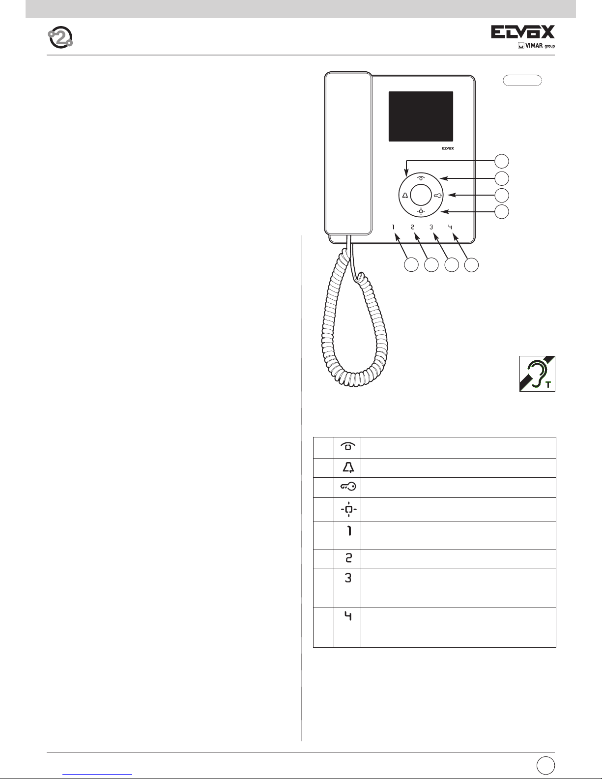
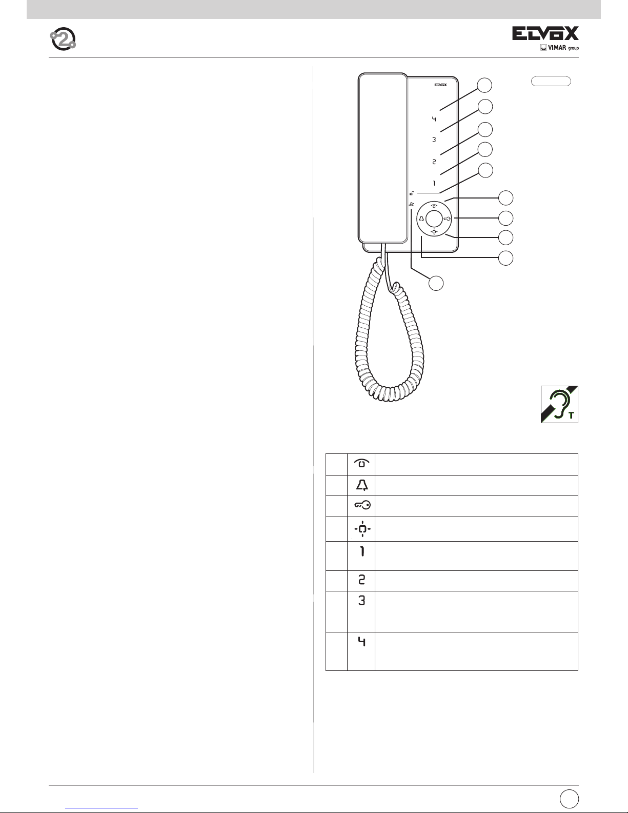
Fig. 1.1
A
C
D
B
E1
E2 E3
E4
*
Description
Monitor made of thermoplastic material with handset and 3.5” LCD colour
display. Equipped with four buttons for the main video door entry functions:
door lock release, self-start, auxiliary services (stair light), ringtone muting
and 4 programmable supplementary keys that can execute up to 4 auxiliary
functions or intercommunicating calls.
The following settings can be made: ringtone volume, ringtone muting when
“User Away” function is activated and ringtone type selection. Option of
setting different ringtones for calls made from different points, e.g.: outdoor
entrance panel, door call, intercommunicating call.
LED signalling of “door/gate open” and “Unanswered calls” (up to 4 calls
with monitor in ringtone muted state).
For use in Elvox Two-Wire systems with power supply 6922.
Article 7529/D has a hearing aid function.
Before commencing programming, read the instructions carefully to
get a clear idea of the product’s characteristics, functions and features.
Technical characteristics
• Surface-mounted monitor made of ABS with mirror gloss finish on front
panel.
• Designed for external wall mounting with metal coupling plate or fitting
to a box (can be mounted directly on the wall using wall plugs or to a
Vimar V71303 type unified 3-module rectangular flush-mount back box
or a 60 or 70 mm round flush-mount back box).
• 3.5” LCD display.
• Touch-sensitive keys with backlit symbols (during operation).
• Power supply from Two-Wire Bus
• Input current:
- on standby: 7mA
- maximum conversation current: 150mA
- peak current limited to call time: 200mA
• Operating temperature: 0° ÷ 40°C
• Electronic chime: different ringtones for panel call, intercom call and
door call.
• 10 different ringtones can be selected.
• Output for additional chime 860A or relay 0170/101.
• Input for door call.
• Input for additional power supply (type 6923).
• Monitor 7529 dimensions: 160x180x45 mm
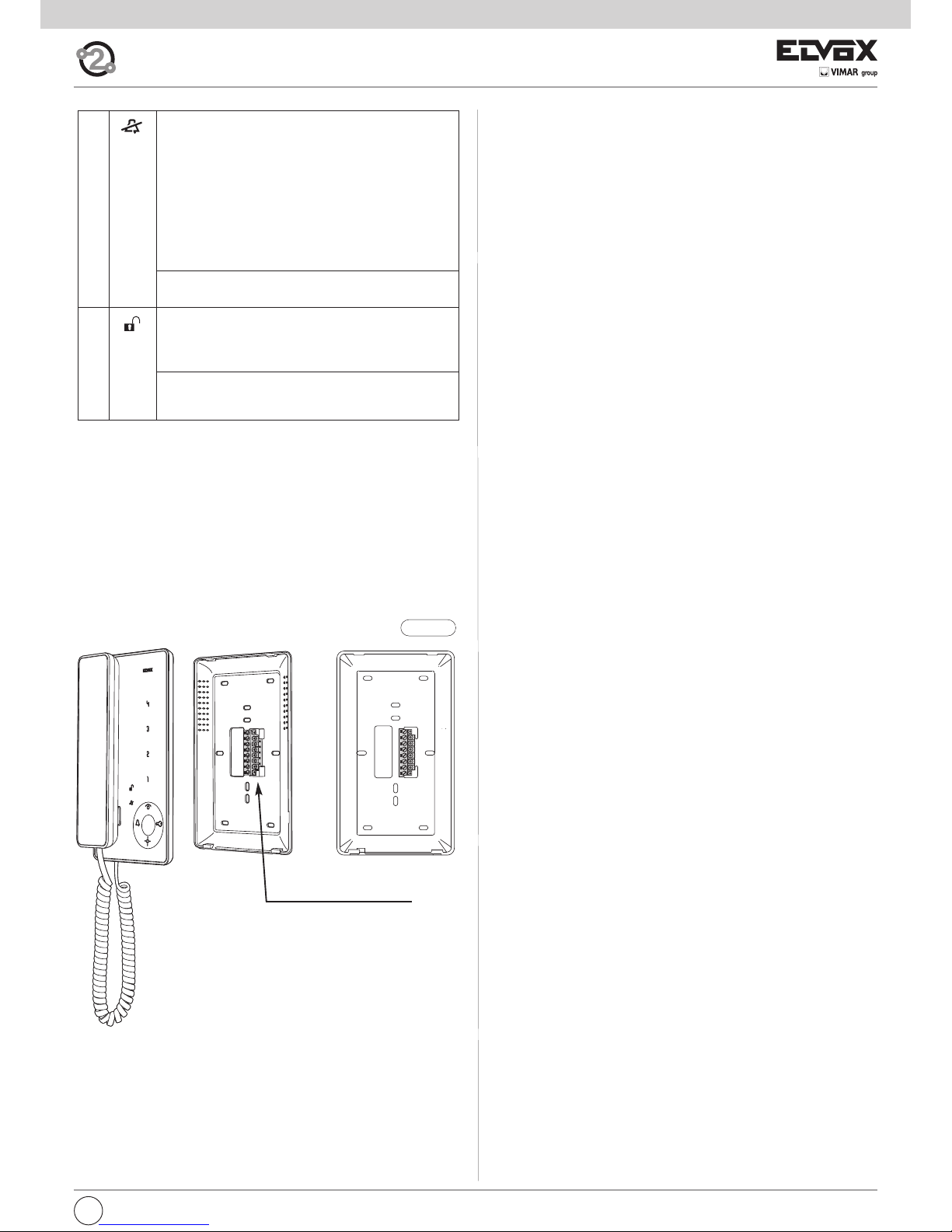
A Self-start: for self-start/auto-activation of interphone (to
Master entrance panel by default).
B Ringtone muting: Mutes ringtone during call.
C Door lock: Lock opening command (programming can be
adjusted using the programmer).
D Auxiliary 1 (Stair light): For auxiliary service (actuator 1 of
relay 69RH or 69PH activated by default).
E1 Button 1: Programmable button to activate auxiliary ser-
vice or intercommunicating call (actuator 2 of relay 69RH or
69PH activated by default).
E2 Button 2: Programmable button to activate auxiliary ser-
vice or intercommunicating call.
E3 Button 3: Programmable button to activate auxiliary ser-
vice or intercommunicating call (entrance panel function F1
activated by default, the last entrance panel to make a call).
E4 Button 4: Programmable button to activate auxiliary ser-
vice or intercommunicating call (entrance panel function F2
activated by default, the last entrance panel to make a call).
Buttons
Page 5

5
GB
M
RESET
2
1
1
2
E+
E-
12V
CH
FP
M
C
50Ω
B
100Ω
A
OPEN
PROG
I
H
Fig. 1.2
L
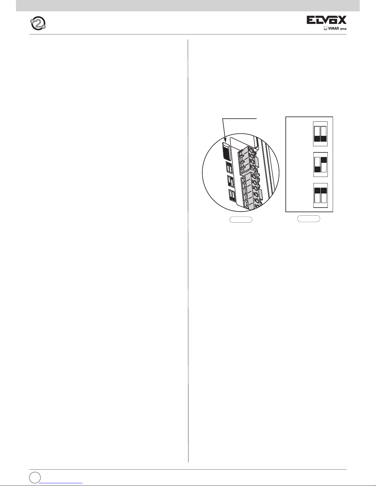
Dip-switch for Bus termination
Connection terminal block
Connection terminal block:
1, 2 Two pairs of terminals for Two-Wire bus
E+, E- Additional power supply for monitor with power supply unit type
6923.
12V Connection of additional chime (positive reference 12V).
CH Connection of additional chime (call repetition).
FP Input for door call button (with reference to terminal M).
M Earth reference.
B During normal operation:
- Flashing light: indicates that the interphone is receiving
a call (from outdoor entrance panel or from an intercommunicating device).
- Steady light: ringtone muted (User Away function).
- Steady light flashing every 10s: if calls have been
made from the entrance panel while the ringtone was
muted, the LED flashes a number of times equal to the
number of calls received from the entrance panel (up to
4 calls are memorised). The flash log is reset when the
ringtone volume is restored.
During programming:
- Flashing light: indicates programming mode.
C During normal operation:
- Steady light: indicates that the door is open if the sen-
sor has been installed on at least one entrance panel
and connected between terminals PA and M.
During adjustment:
- Flashing light: indicates that ringtone selection or vo-
lume adjustment is in progress.
Signals:
Settings
H Brightness setting: allows the screen brightness to be
adjusted.
I Contrast setting: allows contrast to be adjusted.
L Colour setting: allows the colour to be adjusted.
Page 6

GB
6
Hearing aid function (art. 7529/D only)
Art. 7529/D has an internal coil which allows hearing aid wearers to use the
device. In this operating mode, the hearing aid must be switched to the
“T” position. However, for correct operation of the hearing aid refer to its
instruction manual.
Note: metal objects or electronic equipment in the vicinity may affect the
quality of the sound received by the hearing aid.
Operation
Important: For the monitor to work, the ID must have already been pro-
grammed. To check this, press any of the monitor buttons. If an ID has been
assigned to the monitor, a beep will sound when a button is pressed; if no
ID has been assigned or it has been deleted, a triple beep will sound.
Operating times
The answer and conversation times depend on the configuration of the corresponding entrance panel parameters (to change these times, please refer
to the electronic entrance panel unit instructions).
- Answer time (for entrance panel call): Default value 30 s
(minimum value 1 s, maximum value 255 s)
- Answer time (for intercommunicating call): 30 s (fixed value)
- Conversation time (for entrance panel call): Default value 120 s
(minimum value 10 s, maximum value 2550 s)
- Conversation time (for intercommunicating call): Default value 5 minutes
(can be modified to unlimited time).
Answering a call
A call from the outdoor entrance panel or from an intercommunicating device can be answered during the chime cycle or once it has ended. To answer, lift the handset; to end the call, replace the handset.
Receiving a door call
The monitor can receive calls from a door call button if connected to terminals M and FP directly or via interface 6120 (see wiring versions).
When the door call button is pressed, the monitor emits a different tone to
the one used for outdoor entrance panel calls or intercommunicating calls.
To stop the chime, lift the handset.
In the case of a door call by means of a button connected directly to the
monitor’s terminals FP and M; chime cycle duration depends on how long
the button was held down (max. 10 s)
Making an intercommunicating call
To make a call to another indoor unit, one or more buttons must have been
programmed (see “Button programming” section).
To make the call, press the button programmed for the relevant indoor unit.
During the call, the monitor emits a tone in order to signal that the call is
being made. If the interphone/monitor is already engaged in another call, a
tone will be heard on the monitor making the call to indicate that the user
receiving the call is busy.
When the indoor unit receiving the call answers, communication begins automatically. Replace the handset to end the conversation.
The maximum conversation time is 5 minutes (default).
Muting the ringtone during a call (Mute function)
When receiving a call from an outdoor entrance panel or from an intercommunicating device or a door call via device 6120, the call ringtone can be
muted by pressing button B.
Door lock command
Press the lock button (with the handset hooked on or in conversation) to
send a lock opening command to the entrance panel (by default, the last
entrance panel to make a call).
Self-start
- Self-start with dedicated button (button A):
to use the self-start function and communicate with the master entrance
panel, briefly press button A (self-start) to turn on the monitor and lift the
handset to start the conversation. Replace the handset to end the conversation.
- Self-start with programmed button to a specific panel:
to use the self-start function and communicate with a specific entrance
panel, press and release the button programmed to call that entrance
panel (see “Programming the self-activation/self-start button to a specific panel ” section).
Calling a porter switchboard
To call a porter switchboard (if present in the system): lift the handset and
press button C (lock) to make the call.
Page 7
7
GB
2
1
1
2
E+
E-
12V
CH
FP
M
C
50Ω
B
100Ω
A
OPEN
Dip-switch for
Bus termination
Fig. 1.4
B
100Ω
ON
12
C
50Ω
ON
12
Fig. 1.3
A
OPEN
ON
12
Configurations
Choice of ringtones
10 different ringtones can be selected. Different ringtones can also be set
for outdoor, intercommunicating and door calls (see below). The ringtones
must be selected with the monitor on stand-by and the handset on the
hook.
The button for entering configuration mode is button A (self-start).
Button E1 selects the ringtone for ENTRANCE PANEL CALL.
Button E2 selects the ringtone for INTERCOMMUNICATING CALL.
Button E3 selects the ringtone for DOOR CALL (exclusively using the button interface module 6120 or Vimar landing call button). In the case of a
door call by means of a button connected directly to the monitor’s terminals FP and M, the ringtone cannot be changed.
Configuration:
1) Press button A (self-start) and hold down (for 2 s) until the LED C (lock)
begins flashing and the monitor emits an audible signal.
2) Press and hold down the button for the chosen ringtone (button
E1/button E2/button E3) until the ringtone is heard on the monitor.
3) Press the button repeatedly (button E1/button E2/button E3) to select
the desired type of ringtone.
4) After choosing the desired ringtone, press button A or refrain from touching any buttons for 5s to save. After completing the configuration,
the LED flashes and then turns off.
Ringtone volume adjustment
The ringtone volume can be set to 6 levels plus mute.
Press button A (self-start) to enter configuration mode.
Press button B (bell) to lower the ringtone volume.
Press button C (key) to increase the ringtone volume.
The ringtone volume must be adjusted with the monitor on stand-by and
the handset on the hook.
Configuration:
1) Press button A and hold down (for 2 s) until the LED C (lock) begins flashing and the monitor emits an audible signal.
3) Press button B to lower or button C to increase the volume. Each time
the buttons are pressed the volume changes by one level.
4) After choosing the desired volume, press button A or refrain from touching any buttons for 5s to save. After completing the configuration,
the flashing LED goes off and a “beep” is emitted.
Muting the ringtone (User Away function)
Using the volume adjustment procedure described above, pressing button
B a sufficient number of times results in the ringtone being muted. The
“Ringtone muted” status is indicated by the button B LED (ringtone muted)
lighting up steadily.
If the monitor receives a call from the entrance panel while the ringtone is
muted, this is indicated by the LED/button B emitting one flash for each
unanswered call up to a maximum of 4 calls (these flashes occur every 10
s). When the ringtone volume is restored, at least to its minimum level, this
indication will be reset.
Maintenance
Clean the monitor using a soft cloth, which can be dry or slightly dampened with water. Do not pour water directly onto the screen and do not use
any type of chemical product.
Bus termination for video signal stabilisation
The BUS termination dip-switches for video signal stabilization are located
in the rear of the monitor, near the terminal block.
Depending on the connection configuration (interphones/monitors connected in series or derived from a distributor), set the dip-switches in the appropriate position (position A, B or C) according to the instructions given in
the note “Bus termination for ELVOX TWO-WIRE INSTALLATIONS” in the
wiring diagrams section below.
Page 8
GB
8
Manual programming
Basic interphone/monitor programming is as follows:
- Programming ID, which must be performed on the monitor that recei-
ves the call individually or on the first monitor of a group of interphones/monitors with simultaneous calls (master interphone/monitor).
- Programming secondary ID, which must be done for interpho-
nes/monitors associated with a master interphone/monitor.
- Programming programmable buttons or changing the default setting
of supplementary buttons, for auxiliary services or intercommunicating
calls.
Programming must be carried out with the system switched on, without
active communication and only after the interphones/monitors have been
connected to the system and the entrance panels have been programmed.
N.B.: all the programming or deletion phases must be performed with the
interphone/monitor handset lifted and held against the user’s ear.
Programming ID identification code
The identification code is programmed by means of a main entrance panel
(MASTER), already configured and present in the system.
The monitor is supplied without associated identification code. To verify
this, press the lock release button and the monitor should emit an audible
signal (triple beep).
To program the ID, proceed as follows:
1) Lift the handset.
2) Press buttons B and A simultaneously and hold them down until LED B
(ringtone mute) begins flashing.
3) Release the buttons.
4) Press button C and hold it down (for 2 sec.) until the handset emits an
audible signal and communication between the monitor and the outdoor entrance panel begins.
5) Release button C.
Important: you will have 5 s in which to press button C (as indicated in
step 4). If button C is not pressed within the 5 s, steps 1, 2 and 3 must
be repeated.
6) You now have approx 30 seconds to assign the ID code of the external
entrance panel:
- in the case of an alphanumeric panel, key in the primary ID and press
the “bell” button to confirm.
- in the case of a push-button entrance panel, press the button you want
to use to call the monitor.
Important: If the system already contains an interphone/monitor with the
same associated identification code, the entrance panel emits a low tone
and the process must be repeated from the start in order to assign a different code.
Programming secondary ID
Programming the secondary ID is only necessary when you want more than
one monitor to ring in response to the same pushbutton or call code. The
monitors that are to ring at the same time are associated with the same
group. The “master” monitor is programmed first by means of the “identification code programming” procedure described above, while the additional group monitors are programmed with the secondary identification
code.
The maximum number of monitors that can be associated with the same
group without using a 950C programmer is 3 plus a master unit.
Alternatively, a 950C programmer or SaveProg software can be used to
program activation of the ringtone of all Monitors and the monitor of only
the master unit. Before answering from a secondary audio/Monitor, the relevant monitor can be turned on by means of the self-start button.
To program the secondary ID, proceed as follows:
1) Lift the handset.
2) Press buttons B and A simultaneously and hold them down until LED B
(ringtone mute) begins flashing.
3) Release the buttons.
4) Press buttons A and C simultaneously and hold them down (for 2 sec.)
until the handset emits an audible signal and communication between
the monitor and the outdoor entrance panel begins.
5) Release buttons A and C.
Important: you will have 5 s in which to press buttons A and C (as indicated in step 4). If buttons A and C are not pressed within the 5 s,
steps 1, 2 and 3 must be repeated.
6) You now have approx 30 seconds to assign the ID code of the external
entrance panel:
- in the case of an alphanumeric panel, key in the primary ID and press
the “bell” button to confirm.
- in the case of a push-button entrance panel, press the button you want
to use to call the monitor.
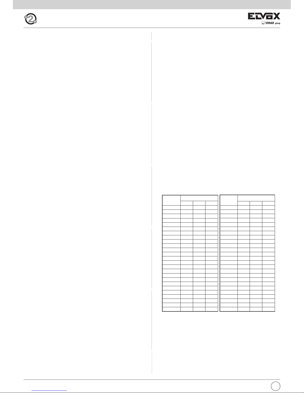
Important: When programming the primary and secondary ID, the monitors
undergoing programming automatically acquire a code that depends on
the association with the button or code used to call the outdoor entrance
panel. Correspondence between the primary ID and the respective secondary ID codes is provided in the table below.
Example: If ID = 8 is given to a second interphone/monitor, the automatic
second interphone/monitor identification attribution procedure will automatically assume ID = 72 (see table).
When a call is made to ID = 8, both monitors/interphones will chime and
both can be used to answer. If, on the other hand, in the case of an alphanumeric panel you enter 72 (the ID automatically assigned by the procedure), a chime is emitted by the interphone/monitor for which the secondary
ID assignation procedure was carried out and only this interphone can be
used to answer the call.
Table of primary and corresponding secondary ID codes:
Important: to delete from a group, the programming deletion procedure
described in the “Default data restore procedure” section must be performed.
Button programming
Important: without programmer 950C or SaveProg software, the only functions that can be assigned are intercommunication, specific entrance
panel self-activation, restoring buttons programmed by the installer to their
default settings and restoring default data.
ID
Primario
ID Secondario
1 2 3
26 126 127 128
27 129 130 131
28 132 133 134
29 135 136 137
30 138 139 140
31 141 142 143
32 144 145 146
33 147 148 149
34 150 151 152
35 153 154 155
36 156 157 158
37 159 160 161
38 162 163 164
39 165 166 167
40 168 169 170
41 171 172 173
42 174 175 176
43 177 178 179
44 180 181 182
45 183 184 185
46 186 187 188
47 189 190 191
48 192 193 194
49 195 196 197
50 198 199 200
ID
Primario
ID Secondario
1 2 3
1 51 52 53
2 54 55 56
3 57 58 59
4 60 61 62
5 63 64 65
6 66 67 68
7 69 70 71
8 72 73 74
9 75 76 77
10 78 79 80
11 81 82 83
12 84 85 86
13 87 88 89
14 90 91 92
15 93 94 95
16 96 97 98
17 99 100 101
18 102 103 104
19 105 106 107
20 108 109 110
21 111 112 113
22 114 115 116
23 117 118 119
24 120 121 122
25 123 124 125
Page 9
9
GB
Button programming procedure for intercommunicating calls
To program the buttons, proceed as follows:
1) Press the “talk/listen” button or lift the handset (depending on model
installed) for the interphone/monitor TO BE CALLED.
2) Lift the handset to be programmed (the caller handset).
3) Press buttons B and A on the monitor to be programmed (caller) simultaneously and hold them down until LED B (ringtone mute) begins flashing.
4) Release buttons B and A.
5) Press and hold down the button to be programmed (e.g. E1, E2, E3, E4).
6) Wait until the monitor handset emits a continuous tone.
7) Release the button to be programmed on the caller monitor.
8) Press a button (lock/F1/F2) on the interphone/monitor to be called.
9) An audible signal in the handset of the (caller) monitor being program-
med confirms that the procedure has been completed correctly.
Procedure for restoring default data for each individual button
(E1, E2, E3, E4)
1) Lift the handset.
2) Press buttons B and A simultaneously and hold them down until LED B
(ringtone mute) begins flashing.
3) Release buttons B and A.
4) Press and hold down the button you want to return to default programming (not valid for Self-start and Lock buttons).
5) Wait until the monitor handset emits an audible signal.
6) Release the button.
7) Press the button again to confirm. The monitor handset will again emit
a signal. The button has now been restored to its default value.
Important: This procedure can be used to manually reprogram all buttons
with the exception of the lock and self-start buttons, for which programmer
950C or SaveProg software is required.
Programming the self-activation/self-start button to a specific pane
l
(different from the self-start function enabled using button “A”)
1) Lift the handset.
2) Press buttons B and A simultaneously and hold them down until LED B
(ringtone mute) begins flashing.
3) Release buttons B and A.
4) Press and hold down the button to be programmed (D, E1, E2, E3, E4).
5) Wait until the monitor handset emits a tone.
6) Release the button.
7) Call the monitor from the panel you want to perform direct self-start
from:
- On push-button entrance panels, press the button corresponding to
the monitor on which the button is being saved.
- On alphanumeric panels, enter the ID corresponding to the monitor
on which the button is being saved and press the bell button on the
panel to confirm.
8) At the end of the procedure described above, the monitor handset emits
an audible signal to indicate that the procedure has been completed
correctly.
Default data restore procedure
1) Lift the handset.
2) Press buttons B and A simultaneously and hold them down until LED B
(ringtone mute) begins flashing.
3) Release buttons B and A.
4) Press and hold down button A again.
5) While the monitor handset is emitting an audible signal, release button
A and press button C briefly.
The monitor programming has now been deleted. To check that programming has been deleted, press button C; the monitor handset should emit
an audible signal.
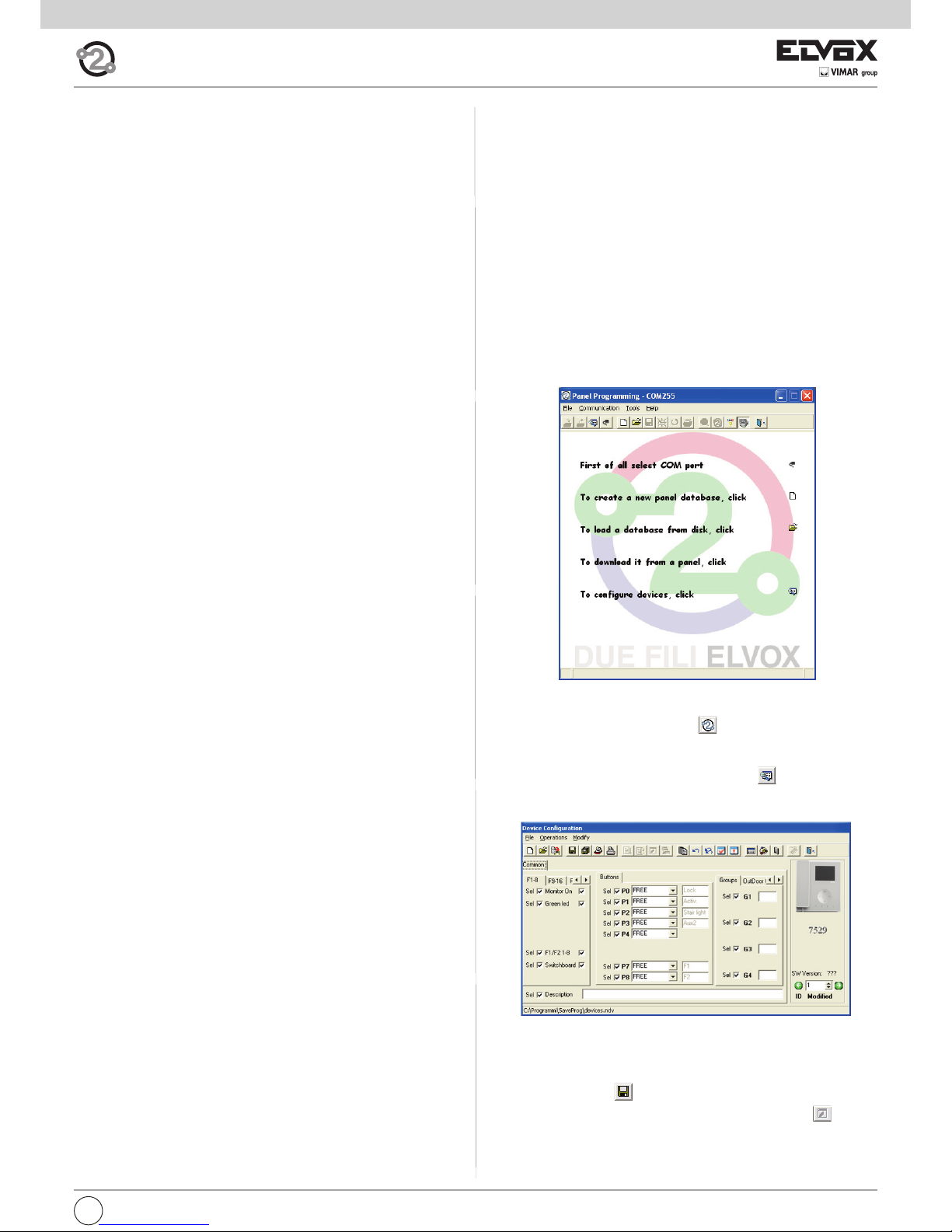
Programming with SAVEPROG software
SaveProg is a PC software package supplied together with interfaces 692I
and 692I/U. These interfaces allow the PC to be connected to an entrance
panel or other suitable device, type 692I via an RS232 port and type 692I/U
via a USB connection.
After connecting the interface and installing SaveProg, on opening the program the following window appears.
It is now possible to proceed with programming in two different ways:
1) with virtual 950C: clicking on icon opens an interactive image of
t950C programmer, which allows programming to be performed by simulating use of the 950C programmer.
2) with the SaveProg windows: clicking on icon opens the “Device
configuration” window.
It is now possible to change button programming, create groups, select
ringtone types, adjust ringtone volume and enable or disable functions.
On completing the desired settings:
- save by clicking on .
- transfer the program to the device by clicking on the icon .
The device has now been reprogrammed.
Programming and configuring with programmer
type 950C
Interphone/monitor programming can be carried out using programmer
type 950C. The programmer must be connected to an entrance panel and
device configuration mode started. This programmer can be used to
change button programming, create groups, select ringtone types, adjust
the ringtone volume and enable or disable functions. For use of the programmer, please refer to the instructions.
Page 10
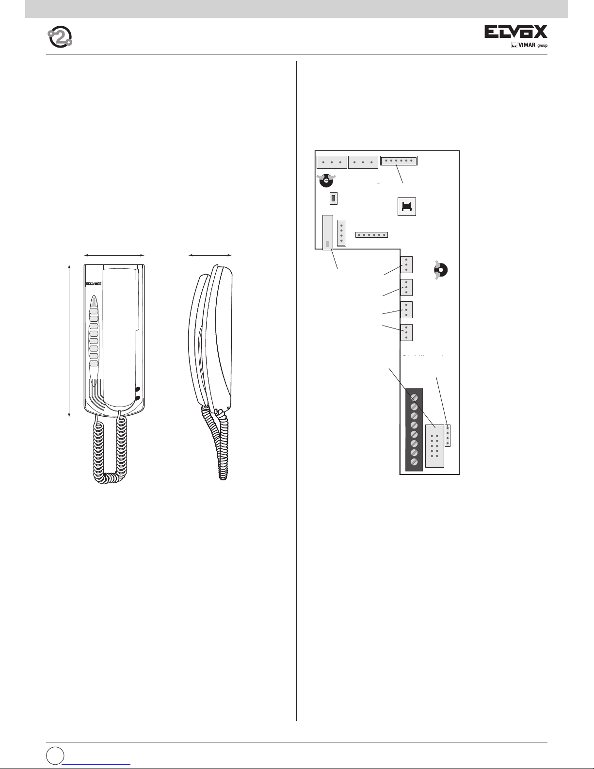
Tab series interphone for Due Fili Elvox (Two-wire systems)
Art. 7509, 7509/D*
Fig. 2.1
A
C
D
B
E4
E3
E2
E1
G
F
GB
10
*
Description
Interphone made of thermoplastic material with handset. Equipped with
four buttons for the main video door entry functions: door lock release,
self-start, auxiliary services (stair light), ringtone muting and 4 programmable supplementary keys that can execute up to 4 auxiliary functions or intercommunicating calls.
The following settings can be made: ringtone volume, ringtone muting
when “User Away” function is activated and ringtone type selection. Option
of setting different ringtones for calls made from different points, e.g.: outdoor entrance panel, door call, intercommunicating call.
LED signalling of “door/gate open” and “Unanswered calls” (up to 4 calls
with interphone in ringtone muted state).
For use in Elvox Two-Wire systems with power supply 6922.
Article 6901/D has a hearing aid function.
Before commencing programming, read the instructions carefully to
get a clear idea of the product’s characteristics, functions and features.
Technical characteristics
• Surface-mounted interphone made of ABS with mirror gloss finish on
front panel.
• Designed for external wall mounting or fitting to a box (can be mounted
directly on the wall using wall plugs or to a Vimar V71303 type unified 3module rectangular flush-mount back box or a 60 or 70 mm round flushmount back box).
• Touch-sensitive keys.
• Power supply from Two-Wire Bus
• Input current:
- on standby: 7mA
- maximum conversation current: 60mA
- peak current limited to call time: 100mA
• Operating temperature: 0° ÷ 40°C
• Electronic chime: different ringtones for panel call, intercom call and door
call.
• 10 different ringtones can be selected.
• Output for additional chime 860A or relay 0170/101.
• Input for door call.
• Interphone 7509 dimensions: 105x180x35 mm
A Self-start: for self-start/auto-activation of interphone (to
Master entrance panel by default).
B Ringtone muting: Mutes ringtone during call.
C Door lock: Lock opening command (programming can be
adjusted using the programmer).
D Auxiliary 1 (Stair light): For auxiliary service (actuator 1 of
relay 69RH or 69PH activated by default).
E1 Button 1: Programmable button to activate auxiliary ser-
vice or intercommunicating call (actuator 2 of relay 69RH or
69PH activated by default).
E2 Button 2: Programmable button to activate auxiliary ser-
vice or intercommunicating call.
E3 Button 3: Programmable button to activate auxiliary ser-
vice or intercommunicating call (entrance panel function F1
activated by default, the last entrance panel to make a call).
E4 Button 4: Programmable button to activate auxiliary ser-
vice or intercommunicating call (entrance panel function F2
activated by default, the last entrance panel to make a call).
Buttons
Page 11
11
GB
Fig. 2.2
F During normal operation:
- Flashing light: indicates that the interphone is receiving
a call (from outdoor entrance panel or from an intercommunicating device).
- Steady light: ringtone muted.
- Steady light flashing every 10s: if calls have been
made from the entrance panel while the ringtone was
muted, the LED flashes a number of times equal to the
number of calls received from the entrance panel (up to
4 calls are memorised). The flash log is reset when the
ringtone volume is restored.
During programming:
- Flashing light: indicates programming mode.
G During normal operation:
- Steady light: indicates that the door is open if the sen-
sor has been installed on at least one entrance panel
and connected between terminals PA and M.
During adjustment:
- Flashing light: indicates that ringtone selection or vo-
lume adjustment is in progress.
Signals:
Connection terminal block:
1, 2 Two pairs of terminals for Two-Wire bus
E+, E- Additional power supply for monitor with power supply unit type
6923.
12V Connection of additional chime (positive reference 12V).
CH Connection of additional chime (call repetition).
FP Input for door call button (with reference to terminal M).
M Earth reference.
Connection terminal block
Operation
Important: For the interphone to work, the ID must have already been pro-
grammed. To check this, press any of the interphone buttons. If an ID has
been assigned to the interphone, a beep will sound when a button is pressed; if no ID has been assigned or it has been deleted, a triple beep will
sound.
Operating times
The answer and conversation times depend on the configuration of the
corresponding entrance panel parameters (to change these times, please
refer to the electronic entrance panel unit instructions).
- Answer time (for entrance panel call): Default value 30 s
(minimum value 1 s, maximum value 255 s)
- Answer time (for intercommunicating call): 30 s (fixed value)
- Conversation time (for entrance panel call): Default value 120 s
(minimum value 10 s, maximum value 2550 s)
- Conversation time (for intercommunicating call): Default value 5 minutes (can be modified to unlimited time).
Answering a call
A call from the outdoor entrance panel or from an intercommunicating device can be answered during the chime cycle or once it has ended. To answer, lift the handset; to end the call, replace the handset.
Receiving a door call
The interphone can receive calls from a door call button if connected to
terminals M and FP directly or via interface 6120 (see wiring versions).
When the door call button is pressed, the interphone emits a different tone
to the one used for outdoor entrance panel calls or intercommunicating
calls. To stop the chime, lift the handset.
In the case of a door call by means of a button connected directly to the
interphone’s terminals FP and M; chime cycle duration depends on how
long the button was held down (max. 10 s).
Making an intercommunicating call
To make a call to another indoor unit, one or more buttons must have been
programmed (see “Button programming” section).
To make the call, press the button programmed for the relevant indoor unit.
During the call, the interphone emits a tone in order to signal that the call
is being made. If the interphone/monitor is already engaged in another call,
a tone will be heard on the interphone making the call to indicate that the
user receiving the call is busy.
When the indoor unit receiving the call answers, communication begins
automatically. Replace the handset to end the conversation.
The maximum conversation time is 5 minutes (default).
Muting the ringtone during a call (Mute function)
When receiving a call from an outdoor entrance panel or from an intercommunicating device or a door call via device 6120, the call ringtone can be
muted by pressing button B.
Door lock command
Press the lock button (with the handset hooked on or in conversation) to
send a lock opening command to the entrance panel (by default, the last
entrance panel to make a call).
Self-start
- Self-start with dedicated button (button A):
to use the self-start function and communicate with the master entrance
panel, lift the handset and briefly press button A (self-start) and lift the
handset to start the conversation. Replace the handset to end the conversation.
- Self-start with programmed button to a specific panel:
to use the self-start function and communicate with a specific entrance
panel, lift the handset and press and release the button programmed to
call that entrance panel (see “Programming the self-activation/self-start
button to a specific panel ” section).
Calling a porter switchboard
To call a porter switchboard (if present in the system): lift the handset and
press button C (lock) to make the call.
Page 12
GB
12
Fig. 2.3
Fig. 2.4
Hearing aid function (art. 7509/D only)
Art. 7509/D has an internal coil which allows hearing aid wearers to use the
device. In this operating mode, the hearing aid must be switched to the “T”
position. However, for correct operation of the hearing aid refer to its instruction manual.
Note: metal objects or electronic equipment in the vicinity may affect the
quality of the sound received by the hearing aid.
Configurations
Choice of ringtones
10 different ringtones can be selected. Different ringtones can also be set
for outdoor, intercommunicating and door calls (see below). The ringtones
must be selected with the interphone/monitor on stand-by and the handset
on the hook.
The button for entering configuration mode is button A (self-start).
Button E1 selects the ringtone for ENTRANCE PANEL CALL.
Button E2 selects the ringtone for INTERCOMMUNICATING CALL.
Button E3 selects the ringtone for DOOR CALL (exclusively using the button interface module 6120 or Vimar landing call button). In the case of a
door call by means of a button connected directly to the interphone’s terminals FP and M, the ringtone cannot be changed.
Configuration:
1) Press button A (self-start) and hold down (for 2 s) until the LED G
“door/gate open” begins flashing and the interphone emits an audible
signal.
2) Press and hold down the button for the chosen ringtone (button
E1/button E2/button E3) until the ringtone is heard on the interphone.
3) Press the button repeatedly (button E1/button E2/button E3) to select
the desired type of ringtone.
4) After choosing the desired ringtone, press button A or refrain from touching any buttons for 5s to save. After completing the configuration, the
LED flashes and then turns off.
Ringtone volume adjustment
The ringtone volume can be set to 6 levels plus mute.
Press button A (self-start) to enter configuration mode.
Press button B (bell) to lower the ringtone volume.
Press button C (key) to increase the ringtone volume.
The ringtone volume must be adjusted with the interphone/monitor on
stand-by and the handset on the hook.
Configuration:
1) Press button A (self-start) and hold down (for 2 s) until the LED G
“door/gate open” begins flashing and the interphone emits an audible signal.
3) Press button B to lower or button C to increase the volume. Each time
the buttons are pressed the volume changes by one level.
4) After choosing the desired volume, press button A or refrain from touching any buttons for 5s to save. After completing the configuration, the
flashing LED goes off and a “beep” is emitted.
Muting the ringtone (User Away function)
Using the volume adjustment procedure described above, pressing button
B a sufficient number of times results in the ringtone being muted. The “Ringtone muted” status is indicated by the LED F (ringtone muted) lighting up
steadily.
If the interphone receives a call from the entrance panel while the ringtone
is muted, this is indicated by the LED F (ringtone muted) emitting one flash
for each unanswered call up to a maximum of 4 calls (these flashes occur
every 10 s). When the ringtone volume is restored, at least to its minimum
level, this indication will be reset.
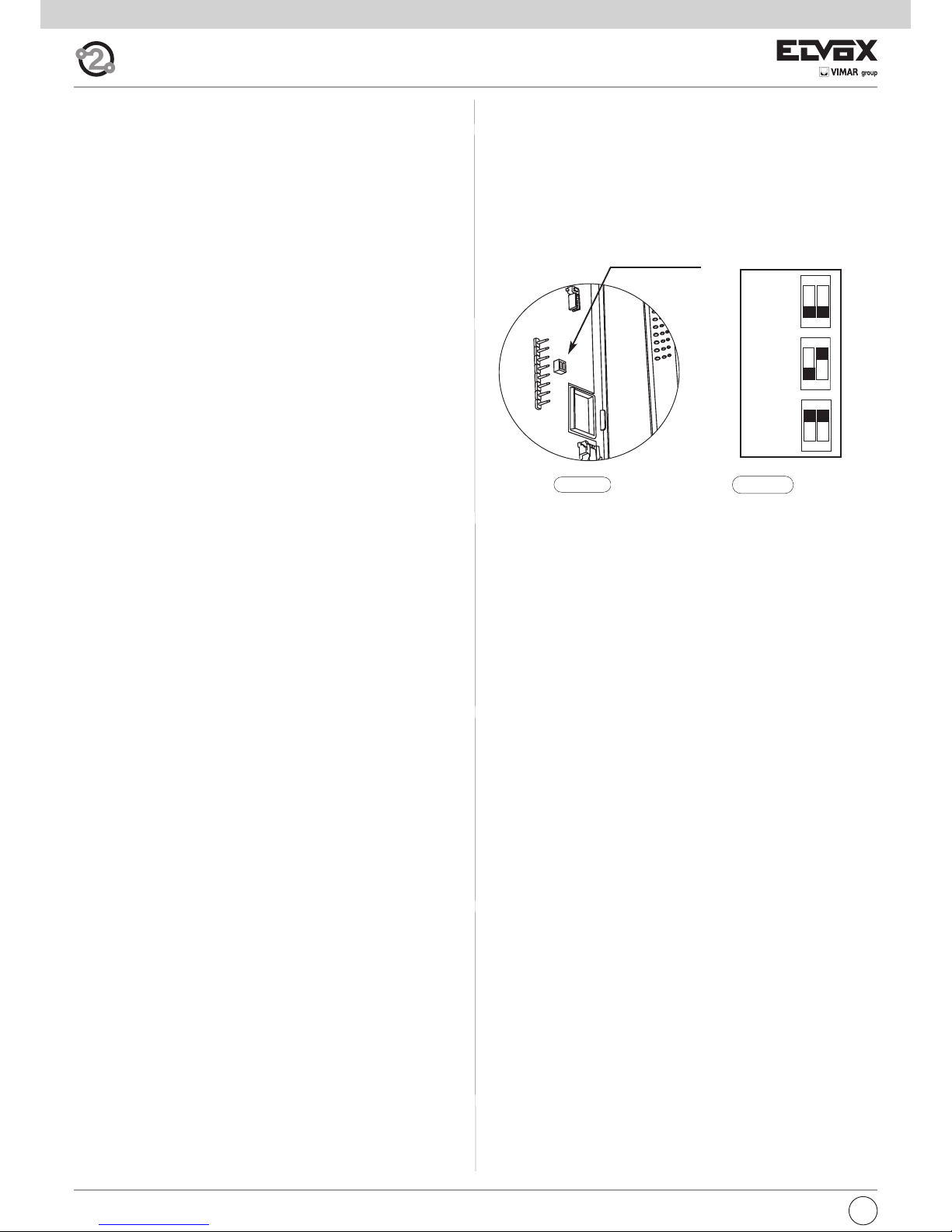
Bus termination for video signal stabilisation
The BUS termination dip-switches for video signal stabilization are located
inside the interphone.
Depending on the connection configuration (interphones/monitors connected in series or derived from a distributor), set the dip-switches in the appropriate position (position A, B or C) according to the instructions given
in the note “Bus termination for ELVOX TWO-WIRE INSTALLATIONS” in
the wiring diagrams section below.
Dip-switch for
Bus termination
A
OPEN
ON
12
B
100Ω
ON
12
C
50Ω
ON
12
Page 13
13
GB
Manual programming
Basic interphone/monitor programming is as follows:
- Programming ID, which must be performed on the interphone that recei-
ves the call individually or on the first interphone of a group of interphones/monitors with simultaneous calls (master interphone).
- Programming secondary ID, which must be done for interphones asso-
ciated with a master interphone/monitor.
- Programming programmable buttons or changing the default setting of
supplementary buttons, for auxiliary services or intercommunicating calls.
Programming must be carried out with the system switched on, without active communication and only after the interphones/monitors have been connected to the system and the entrance panels have been programmed.
N.B.: all the programming or deletion phases must be performed with
the interphone/monitor handset lifted and held against the user’s ear.
Programming ID identification code
The identification code is programmed by means of a main entrance panel
(MASTER), already configured and present in the system.
The interphone is supplied without associated identification code. To verify
this, press the lock release button and the interphone should emit an audible signal (triple beep).
To program the ID, proceed as follows:
1) Lift the handset.
2) Press buttons B and A simultaneously and hold them down until LED F
(ringtone mute) begins flashing.
3) Release the buttons.
4) Press button C and hold it down (for 2 sec.) until the handset emits an
audible signal and communication between the interphone and the outdoor entrance panel begins.
5) Release button C.
Important: you will have 5 s in which to press button C (as indicated in step
4). If button C is not pressed within the 5 s, steps 1, 2 and 3 must be repea-
ted.
6) You now have approx 30 seconds to assign the ID code of the external
entrance panel:
- in the case of an alphanumeric panel, key in the primary ID and press
the “bell” button to confirm.
- in the case of a push-button entrance panel, press the button you
want to use to call the interphone.
Important: If the system already contains an interphone with the same associated identification code, the entrance panel emits a low tone and the
process must be repeated from the start in order to assign a different code.
Programming secondary ID
Programming the secondary ID is only necessary when you want more than
one interphone/monitor to ring in response to the same pushbutton or call
code. The interphones/monitors that are to ring at the same time are associated with the same group. The “master” interphone/monitor is programmed first by means of the “identification code programming” procedure
described above, while the additional group interphones/monitors are programmed with the secondary identification code.
The maximum number of interphones/monitors that can be associated with
the same group without using a 950C programmer is 3 plus a master unit.
Alternatively, a 950C programmer or SaveProg software can be used to program activation of the ringtone of all video door entry units and the monitor
of only the master unit. Before answering from a secondary audio/video
door entry unit, the relevant monitor can be turned on by means of the selfstart button.
To program the secondary ID, proceed as follows:
1) Lift the handset.
2) Press buttons B and A simultaneously and hold them down until LED F
(ringtone mute) begins flashing.
3) Release the buttons.
4) Press buttons A and C simultaneously and hold them down (for 2 sec.)
until the handset emits an audible signal and communication between
the interphone and the outdoor entrance panel begins.
5) Release buttons A and C.
Important: you will have 5 s in which to press buttons A and C (as indicated in step 4). If buttons A and C are not pressed within the 5 s, steps 1, 2
and 3 must be repeated.
6) You now have approx 30 seconds to assign the ID code of the external entrance panel:
- in the case of an alphanumeric panel, key in the primary ID and
press the “bell” button to confirm.
- in the case of a push-button entrance panel, press the button you
want to use to call the interphone.
Important: When programming the primary and secondary ID, the interphones undergoing programming automatically acquire a code that depends on the association with the button or code used to call the outdoor
entrance panel. Correspondence between the primary ID and the respective secondary ID codes is provided in the table below.
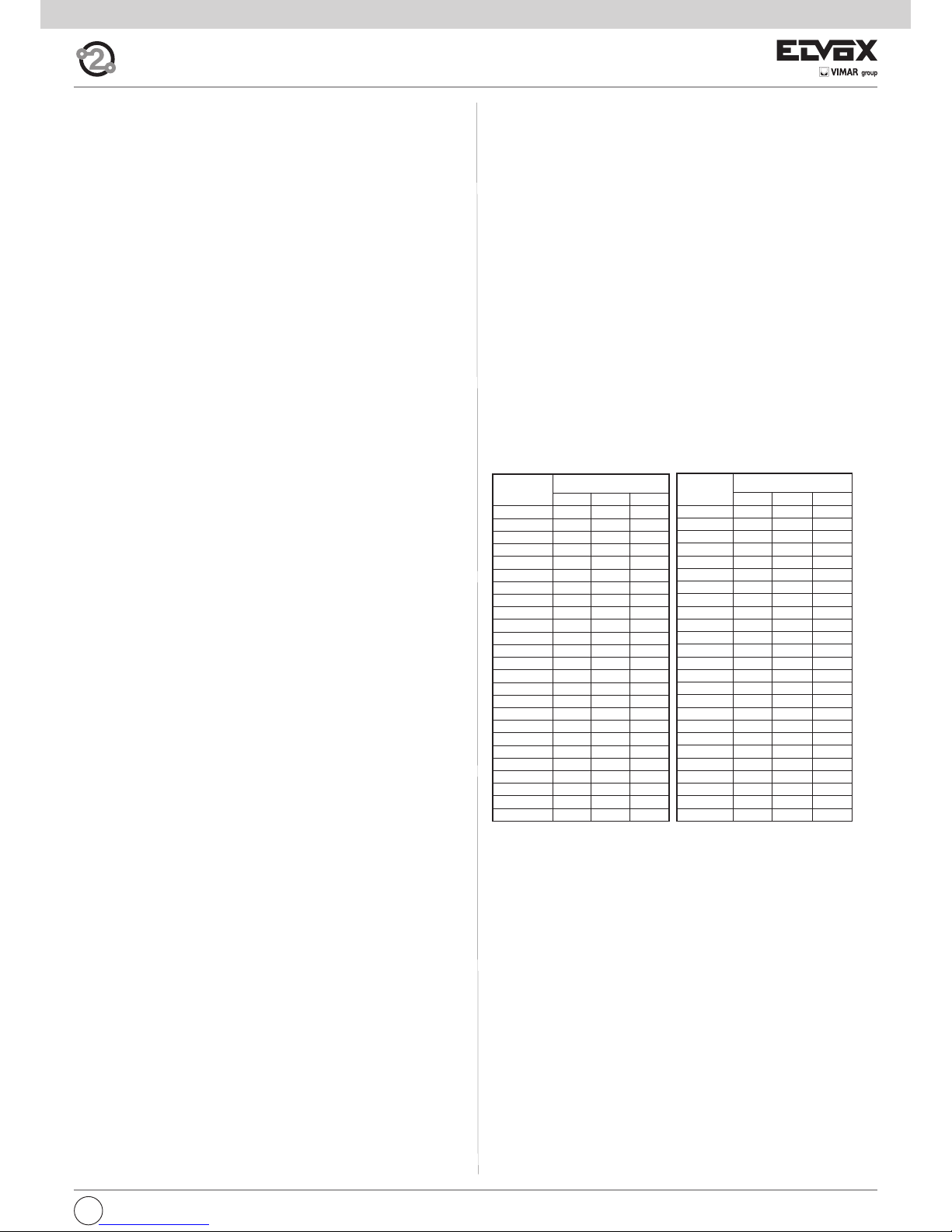
Example: If ID = 8 is given to a second interphone, the automatic second
interphone identification attribution procedure will automatically assume ID
= 72 (see table).
When a call is made to ID = 8, both interphones will chime and both can be
used to answer. If, on the other hand, in the case of an alphanumeric panel
you enter 72 (the ID automatically assigned by the procedure), a chime is
emitted by the interphone for which the secondary ID assignation procedure was carried out and only this interphone can be used to answer the
call.
Table of primary and corresponding secondary ID codes:
Important: to delete from a group, the programming deletion procedure de-
scribed in the “Default data restore procedure” section must be performed.
Button programming
Important: without programmer 950C or SaveProg software, the only functions that can be assigned are intercommunication, specific entrance
panel self-activation, restoring buttons programmed by the installer to their
default settings and restoring default data.
Button programming procedure for intercommunicating calls
To program the buttons, proceed as follows:
1) Press the “talk/listen” button or lift the handset (depending on model installed) for the interphone/monitor TO BE CALLED.
2) Lift the handset to be programmed (the caller handset).
3) Press buttons B and A on the interphone to be programmed (caller) si-
multaneously and hold them down until LED F (ringtone mute) begins
flashing.
4) Release buttons B and A.
5) Press and hold down the button to be programmed (e.g. E1, E2, E3, E4).
6) Wait until the interphone handset emits a continuous tone.
7) Release the button to be programmed on the caller interphone.
8) Press a button (lock/F1/F2) on the interphone/monitor to be called.
9) An audible signal in the handset of the (caller) interphone being programmed confirms that the procedure has been completed correctly.
Primary ID
Secondary ID
1 2 3
26 126 127 128
27 129 130 131
28 132 133 134
29 135 136 137
30 138 139 140
31 141 142 143
32 144 145 146
33 147 148 149
34 150 151 152
35 153 154 155
36 156 157 158
37 159 160 161
38 162 163 164
39 165 166 167
40 168 169 170
41 171 172 173
42 174 175 176
43 177 178 179
44 180 181 182
45 183 184 185
46 186 187 188
47 189 190 191
48 192 193 194
49 195 196 197
50 198 199 200
Primary ID
Secondary ID
1 2 3
1 51 52 53
2 54 55 56
3 57 58 59
4 60 61 62
5 63 64 65
6 66 67 68
7 69 70 71
8 72 73 74
9 75 76 77
10 78 79 80
11 81 82 83
12 84 85 86
13 87 88 89
14 90 91 92
15 93 94 95
16 96 97 98
17 99 100 101
18 102 103 104
19 105 106 107
20 108 109 110
21 111 112 113
22 114 115 116
23 117 118 119
24 120 121 122
25 123 124 125
Page 14
GB
14
Procedure for restoring default data for each individual button
(E1, E2, E3, E4)
1) Lift the handset.
2) Press buttons B and A simultaneously and hold them down until LED F
(ringtone mute) begins flashing.
3) Release buttons B and A.
4) Press and hold down the button you want to return to default programming (not valid for Self-start and Lock buttons).
5) Wait until the interphone handset emits an audible signal.
6) Release the button.
7) Press the button again to confirm. The interphone handset will again
emit a signal. The button has now been restored to its default value.
Important: This procedure can be used to manually reprogram all buttons
with the exception of the lock and self-start buttons, for which programmer
950C or SaveProg software is required.
Programming the self-activation/self-start button to a specific
panel
(different from the self-start function enabled using button “A”)
1) Lift the handset.
2) Press buttons B and A simultaneously and hold them down until LED F
(ringtone mute) begins flashing.
3) Release buttons B and A.
4) Press and hold down the button to be programmed (D, E1, E2, E3, E4).
5) Wait until the interphone handset emits an audible signal.
6) Release the button.
7) Call the interphone from the panel you want to perform direct self-start
from:
- On push-button entrance panels, press the button corresponding to
the interphone on which the button is being saved.
- On alphanumeric panels, enter the ID corresponding to the inter-
phone on which the button is being saved and press the bell button
on the panel to confirm.
8) At the end of the procedure described above, the interphone handset
emits an audible signal to indicate that the procedure has been completed correctly.
Default data restore procedure
1) Lift the handset.
2) Press buttons B and A on the interphone to be programmed (caller)
simultaneously and hold them down until LED F (ringtone mute) begins
flashing.
3) Release buttons B and A.
4) Press and hold down button A again.
5) While the interphone handset is emitting an audible signal, release button A and press button C briefly.
The interphone programming has now been deleted. To check that programming has been deleted, press button C; the interphone handset should
emit an audible signal.
Programming with SAVEPROG software
SaveProg is a PC software package supplied together with interfaces type
692I and type 692I/U. These interfaces allow the PC to be connected to an
entrance panel or other suitable device, type 692I via an RS232 port and
type 692I/U via a USB connection.
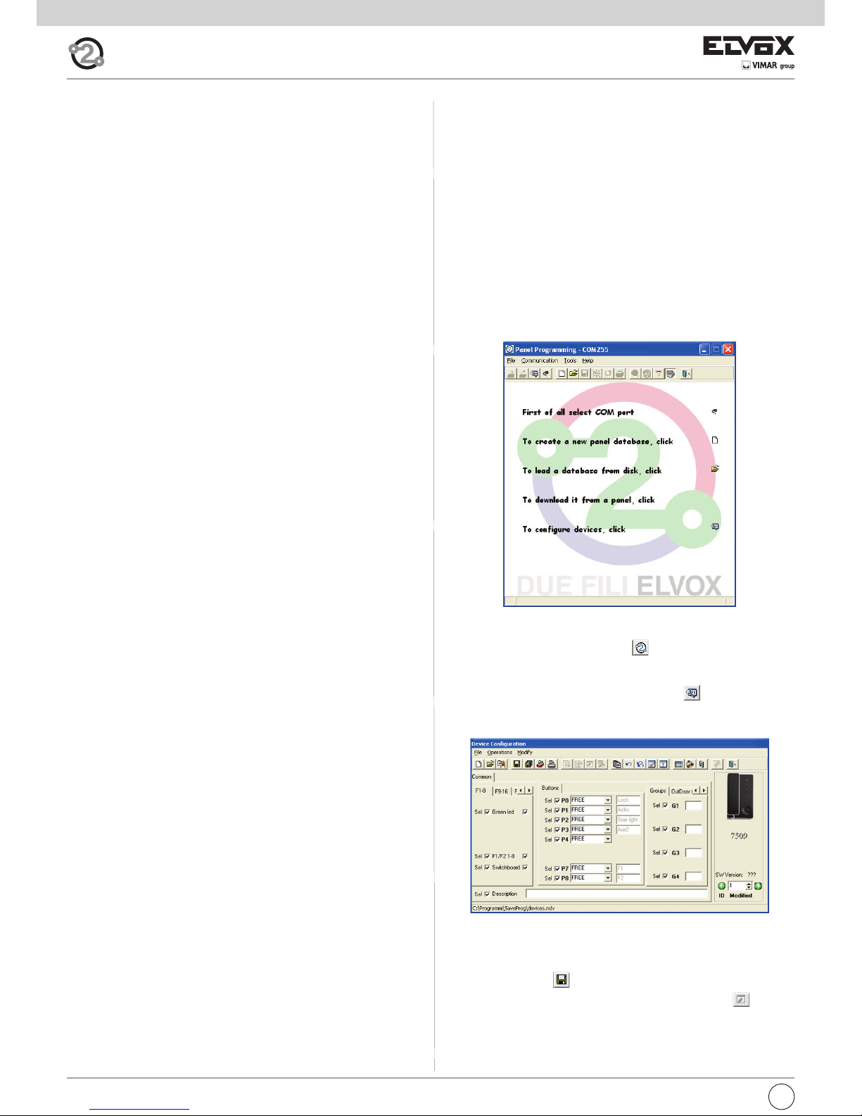
After connecting the interface and installing SaveProg, on opening the program the following window appears.
It is now possible to proceed with programming in two different ways:
1) with virtual 950C: clicking on icon opens an interactive image of
the 950C programmer, which allows programming to be performed by
simulating use of the 950C programmer.
2) with the SaveProg windows: clicking on icon opens the “Device
configuration” window.
It is now possible to change button programming, create groups, select
ringtone types, adjust ringtone volume and enable or disable functions.
On completing the desired settings:
- save by clicking on .
- transfer the program to the device by clicking on the icon .
The device has now been reprogrammed.
Programming and configuring with programmer
type 950C
Interphone/monitor programming can be carried out using programmer
type 950C. The programmer must be connected to an entrance panel and
device configuration mode started. This programmer can be used to
change button programming, create groups, select ringtone types, adjust
the ringtone volume and enable or disable functions. For use of the programmer, please refer to the instructions.
Page 15
GB
15
Fig. 3.5
226 mm
65 mm
89 mm
Interphone series Petrarca
type 6209
Description
Type 6209 is an interphone in the Petrarca series for ELVOX 2-WIRE audio
and video door entry systems. It is supplied as standard with 3 pushbuttons, one for lock release, one for self-start of the interphone in the system
even when not called, and one for the auxiliary “stair light” service. The interphone can be fitted with an additional 3 pairs of pushbutton types 692P
(692P/M or 692P/R), for auxiliary services or intercommunicating calls, and
the accessory type 6153/682 for: call volume adjustment, call signal mute,
call denied luminous indicators, signal to indicate unanswered calls, signal
to indicate services not available and luminous signal for gate/door open.
The interphone can be installed as a wall-mounted version or desktop
using the conversion kit type 6140 or 6A40, or in combination with monitors in the Petrarca series type 6029 (b/w monitor) or type 6029/C (colour
monitor) by means of wall bracket type 6145 or desktop conversion kit
type 6142 or 6A42.
Connection and connector terminal board
1, 2) BUS line.
4, 6P) Connection for door call pushbutton.
5, 6S) Connection of additional door ringtone
-, +)
Additional power supply for monitor with power supply type 6923.
VARIAT.) Connection for module type 6153/682.
VIDEO) Connection for monitor type 6029 or 6029/C.
T1) 1st pair of pushbuttons type 692P.
T2) 2nd pair of pushbuttons type 692P.
T3) 3rd pair of pushbuttons type 692P.
T4) 4th pair of pushbuttons type 692P.
Controls
The call volume can be adjusted by moving the loudspeaker wire from
connector A+ (high) to A- (low); otherwise use accessory type 6153/682,
leaving the loudspeaker wire connected to connector A-.
Fig. 3.4
BL BIRO A+ CAA- VA RI AT.
SERR.
SERIALE
PRG.
T1
T2
T3
T4
VIDEO
1
1
2
4
5
6S
6P
-
+
T1
T2
T3
T4
Per art. 6153/682
RESET
SERRATURA
Per art. 6009 o
6009/C
Stabilizzazione
segnale video
TR1
TR2
Video signal
stabiliser
TR1, TR2) Do not touch, trimmers already set by the firm.
For
Lock
For Art. 6029 o
Art. 6029/C
INSTALLATION
Wall-mounted installations of the interphone do not require additional accessories.
However a vertical 3-module box may be used to facilitate fixture and cable
routing. For desktop installations and combinations with monitors, refer to
the respective instructions of the conversion kit or monitor.
Page 16

16
GB
A
C
B
Fig. 3.7
B
A
A
A
Fig. 3.6
VIDEO SIGNAL STABILISATION
Inside the interphone there are some connectors (A-B-C) and some jumpers for the video signal stabilization.
This jumper must be used in video installations
with several appliances (interphones and monitors) connected in series (Fig. 3.6).
In series configuration displace the jumper
(only in the last set) into “B” position and keep
the jumpers of other interphones/monitors in
the initial position, i.e. “A”. (Fig. 3.6).
For other wiring configurations see note: "Bus
termination for ELVOX TWO-WIRE installations"
provided (Page. 44).
PROGRAMMING
There are three interphone programming modes: assignment of an identification code or call code (indispensable), assignment of a secondary
identification code (for interphones associated with a master interphone),
programming of pushbuttons for auxiliary services and intercommunicating calls (when necessary).
Programming must be performed with the system switched on, without
active communication and only after connecting the interphones/monitors
to the system and programming the panels.
Identification code programming
The identification code is programmed via an entrance panel (MASTER),
already configured and present on the system.
The interphone is supplied without associated identification code. To verify this condition, press the lock release pushbutton and the interphone
should emit a triple “Beep”.
Attention: during the interphone/video interphone identification code
programming you have 30 seconds from the moment you enter the
programming in the interphone/video interphone and the moment
you press the call push-button on the panel or you send the code.
Programming phase:
1) Remove the interphone cover.
2) Press and hold the RESET pushbutton on the interphone.
3) Press and hold the tab on the lock release pushbutton, together with
the RESET pushbutton.
4) Release the RESET pushbutton, keeping the lock release pushbutton
pressed.
5) After 2 seconds the interphone emits a high tone and communication
is enabled with the panel. If the monitor is also connected to the interphone, it is switched on and connected to the camera of the entrance
panel.
6) Release the tab of the lock release pushbutton.
7) On pushbutton entrance panels, press the call button for the interphone, while on alphanumeric keypads, enter the call code and press
pushbutton “ ”.
8) If the system contains an interphone that already has the same associated identification code, the panel emits a low signal and the operation should be repeated from point 2.
9) Otherwise the code is associated with the interphone and communication is terminated.
Page 17

GB
17
Intercommunicating call pushbutton programming
Programming phase:
1) Raise
the handset of the interphone/video interphone to call
(when using series 8870, Giotto, Petrarca). With other versions of
series 6600 (without handset) press and keep pressed the
talk/listen push-button .
2) Remove the cover of the interphone to be programmed.
3) Press and hold the RESET push-button on the audio door entry unit to
program.
4) Press and hold the additional pushbutton to make the intercommunicating call together with the RESET pushbutton.
5) Release the RESET pushbutton, keeping the call pushbutton pressed.
6) After 2 seconds the interphone emits a high tone, while the other interphone emits a 3-tone ascending scale.
7) Release the intercommunicating call pushbutton.
8) On the interphone called (with the 3-tone ring), press one of the programmed pushbuttons (such as lock, F1, F2 or actuator).
9) A high tone confirms the end of the procedure.
Repeat the same procedure for the other interphones and any other intercommunicating call pushbuttons.
Programming the self-start pushbutton to a specific panel.
Programming phase:
1) Remove the interphone cover.
2) Press and hold the RESET pushbutton on the interphone.
3) Press and hold the additional pushbutton to activate the self-start fun-
ction together with the RESET pushbutton.
4) Release the RESET pushbutton, keeping the self-start pushbutton
pressed.
5) After 2 seconds the interphone emits a high tone.
6) Release the self-start pushbutton.
7) On pushbutton entrance panels, press the call button for the inter-
phone, while on alphanumeric keypads, enter the call code and press
pushbutton “ ”.
8) A high tone confirms the end of the procedure.
Restoring default values of pushbuttons
(P2,P3,P4,P5,P6,P7,P8)
Programming phase:
1) Remove the interphone cover.
2) Press and hold the RESET pushbutton on the interphone.
3) Press and hold the relative pushbutton to be reprogrammed together
with the RESET pushbutton.
4) Release the RESET pushbutton, keeping the other pushbutton pressed.
5) After 2 seconds the interphone emits a high tone.
6) Release the pushbutton to restore to default and then press again.
Deleting all settings.
Programming phase:
This procedure is advised when you want to change the ID of an interphone/monitor previously programmed and you do not want keep the operation programming of the appliance.
1) Remove the interphone cover.
2) Press and hold the RESET pushbutton on the interphone.
3) Press and hold the self start pushbutton together with the RESET pu-
shbutton.
4) Release the RESET pushbutton, keeping the self-start pushbutton
pressed.
5) After 2 seconds the interphone emits a continuous tone for two se-
conds.
6) Release the self-start pushbutton.
7) During the continuous tone, press the tab on the lock release pushbut-
ton.
If the deletion procedure is successful, when the lock release tab is
pressed once more the interphone emits a triple “Beep”.
Secondary identification code programming
Programming of the secondary identification code is only required when
more than one interphone is to be called by means of the same pushbutton or call code. The interphones that ring at the same time are associated with the same group. The “master” interphone is programmed first by
means of the “identification code programming” procedure described
above, while the additional group interphones are programmed with the
secondary identification code (see table page 44).
A maximum of three audio door entry units plus one group master can
be associated with the same group, without the need for programmer
Type 950C or SaveProg .
If the interphones are combined with Petrarca monitors, an additional
power supply type 6923 must be fitted for each additional monitor
after the second monitor. Using programmer type 950C, activation of
the ringtone on all monitors can be programmed, without simultaneous activation of all monitors, to then enable activation of the monitor from the interphone used to answer the call with the self-start
pushbutton; this avoids the need to use additional power supplies.
Programming phase:
1) Remove the interphone cover.
2) Press and hold the RESET pushbutton on the interphone.
3) Press and hold the tab on the lock release pushbutton and the self
start/auto-activation pushbutton (the first pushbutton below the tab),
together with the RESET pushbutton.
4) Release the RESET pushbutton, keeping the other two pushbuttons
pressed.
5) After 2 seconds the interphone emits a high tone and communication
is enabled with the panel. If the monitor is also connected to the interphone, it is switched on and connected to the camera of the entrance
panel.
6) Release the tab on the lock release pushbutton and the self start pushbutton.
7) On pushbutton entrance panels, press the call button for the “master”
interphone, while on alphanumeric keypads, enter the call code of the
“master” interphone and press pushbutton “ ”.
8) When the secondary code is associated with the interphone and communication is terminated.
To know the number assigned see table shown in the wiring diagram section.
Pushbutton programming
The interphone is supplied with a pair of additional pushbuttons type 692P,
for the functions self start and the auxiliary service “stair light”, which activates the 1st relay of the 1st actuator (type 692R), if connected to the system. A further three pairs of pushbuttons type 692P can be inserted in
the interphone, to be connected to connectors T2-T3-T4, corresponding to
the following default functions.
Pushbutton Connector In program. Default function
1° T1 P1 Self-start
2° T1 P2 Stair light (1st relay of 1st
actuator, type 692R)
3° T2 P3 Auxiliary (2nd relay of 1st
actuator, type 692R)
4° T2 P4 Not associated
5° T3 P5 Not associated
6° T3 P6 Not associated
7° T4 P7 Function F1 on panel
8° T4 P8 Function F2 on panel
P0 is the lock button.
To change the operating mode of buttons P0 and P1, use programmer type
950C or the Save Prog software.
Page 18

18
GB
OPERATION
Calls from an entrance panel, intercommunicating calls and door calls are
differentiated by means of different tones.
Door calls.
Calls from entrance panels do not follow the pressed pushbutton but are
generated inside the interphone. The call interval is 1 s of ringtone and 2 s
of pause repeated twice (default value set on panel). To answer, raise the
handset. If the handset is already raised during the call, replace and raise
it again. The call answer time (30 s) and the conversation time (2 minutes
by default) are set in the panel parameters. When the conversation time
has elapsed, the user can continue without replacing the handset if a new
call is made within 10 s from the same panel.
Intercommunicating call.
Lift the handset and press the intercommunicating button for the interphone/monitor to be called. On the handset of the interphone called a call
tone will ring (if the call is enabled) or an engaged tone (if not enabled). On
the called interphone the ringtone starts sequentially at intervals of 1 s ringing and 4 s pause. The maximum duration of the call is 30 s (6 cycles). To
answer the call, simply raise the handset; the maximum duration of the
conversation is 60 seconds. When the conversation time has elapsed, the
user can continue without replacing the handset if a new call is made within 10 s. Calls from the panel have priority over intercommunicating calls.
Denied calls.
Installation of type 6153/682 in the interphone, enables the user to vary
the call intensity or mute the ringtone. Call mute is indicated by permanent illumination of the red LED. If calls are made to the interphone when
the call mute is enabled, they are denied. A denied call causes the red Led
to briefly switch off according to the number of times calls are denied (maximum 4 denied calls). The signal is repeated every 10 s (approx.). Deletion
of denied calls is by: reenabling the ringtone, resetting the interphone or a
system power failure. On the panel, a denied call is indicated by means of
a dissuasion tone (a series of “Beeps” at 100ms intervals with a pause of
100ms for a total of 5 s).
The message “Do not disturb” also appears on panels with display.
Lock Button
The lock button of each device works in the following manner.
- Device with handset at rest lock to the last entrance panel with
which it has spoken or from which it has been called.
- Device with handset raised but not engaged in a conversation
call to switchboard if the Switchboard flag is YES. Otherwise it goes
back to the first case.
- Device with handset raised and engaged in an internal conversation
as in the first case.
- Device with handset raised and engaged in an external conversation or
called from entrance panel lock to the entrance panel being spoken with or from which it has been called.
In practice a lock is always activated except when the handset is raised
and you immediately press the lock button. This can also be taken to the
standard case if the system has no porter switchboard and the Switchboard flag is set on NO.
Type 6029 - 6029/C
PETRARCA SERIES MONITOR FOR TWO ELVOX WIRES
DESCRIPTION
PETRARCA series monitor type
6029
or 6029/C
can work in conjunction
with interphone type
6209 or 62I8
for video door entry systems series
TWO WIRES ELVOX or TWO WIRES VIDEOKIT.
TECHNICAL CHARACTERISTICS OF type 6029
- Slim-line surface wall-mounted monitor with 3.5” B/W
- Video signal standard: CCIR with 625 lines and 50 frames (EIA standard available on request)
- Passband: 4 MHz
TECHNICAL CHARACTERISTICS OF type 6029/C
- Slim-line surface wall-mounted monitor with LCD colour screen 3.5”
- Video signal standard: PAL
Contrast (colour) Brightness
MONITOR DIMENSIONS AND ADJUSTMENTS
226 mm
48 mm135 mm
Fig. 3.8
Page 19

GB
19
Monitor series Giotto
type 6329, 6329/C
Description
Type 6329 and 6329/C are interphones in the Giotto series respectively
with B/W (6329) and colour screen (6329/C) for ELVOX 2-WIRE video door
entry systems. They are supplied as standard with 3 pushbuttons, one for
lock release, one for self-start of the monitor in the system even when not
called, and one for the auxiliary “stair light” service. Supplied with call volume adjustment on 3 levels and call mute. The luminous indicators of: call
signal mute, unanswered calls, services not available and gate/door open,
are signalled by means of two LEDs (red and green) present on the monitor.
The monitor can be installed as a wall-mounted version, by means of the
bracket (R684) supplied with the monitor, or desktop version by means of
the conversion kit type 661A or 661F.
220 mm
71 mm204 mm
Fig. 4.1
Monitor technical specifications
- Wall-mounted monitor in ABS
- Backing plate and plugs for wall-mounted fixture or 3-module box.
- 3.5" flat screen for 6329 and 3.5" flat screen for 6329/C.
- Electronic circuit on interchangeable cards.
- Standard video signal CCIR 625 lines 50 squares for 6329 and PAL for
6329/C.
- Video pass band 4 MHz
- Operating temperature from 0° to +40° C.
- Electronic ringtone.
- Input for door calls with different ringtone from panel calls.
- Output for additional ringtone type 860A.
- Supply of data from bus.
- Input for additional power supply (type 6923) if the system is configured
to enable simultaneous activation of more than two monitors.
Connection and connector terminal board
3, 4) Additional ringtone connection
1, 2) BUS line.
12 +, 13 -) Additional power supply for monitor with power supply type 6923.
V3, M) Connection for door call pushbutton.
CN1) Connection for monitor.
Fig. 4.2
ELVOX
CS2350
271103
4 3 2 1
A S+BUS
12 13 V3 M
EXT. 24V
F.P.
+ -
CN2
C
B
A
CN1
Stabilizzazione
segnale video
Per monitor
Video signal
stabilization
For monitor
Page 20

20
GB
B
A
A
A
Fig. 4.5
Fig. 4.3
Fig. 4.4
D
F
E
H
I
A
C
B
G
P1
P2
P0
P1 + P2 (Toghether) =
P3
A
B
C
Fig. 4.6
Controls and adjustments (Fig. 4.4 - 4.5)
A - Ringtone volume and mute control.
B - Brightness control.
C - Contrast control for 6329 and color for 6329/C
D - Lock release pushbutton .
E - System self-start pushbutton .
F - Pushbutton for auxiliary service, 1st relay of 1st actuator type
69RH.
When the pushbuttons and are pressed together, a second
auxiliary service is activated, 2nd relay of 1st actuator type 69RH.
G - RESET pushbutton for monitor programming.
H - Ringtone mute LED. The fixed light illuminates when the ringtone mute
is enabled by means of slider "A" and flashes when calls have been
denied (red led).
I - Door open LED. On systems in which this function is used, the LED re-
mains lit permanently when the door/gate is open (green led).
VIDEO SIGNAL STABILISATOR
On the monitor intercommunication card
there is a connector (A-B-C) and a jumper for
the video signal balance (Fig. 4.5).
This jumper must be used on the installations
where there are more appliances (interphones or monitors) connected in series (Fig.
4.5).
Displace the jumper into "B" (Termination 100
Ohm) only on the last set and keep the jumpers on the other appliances in the initial position "A" (No termination).
For other wiring configurations see note:
"Bus termination for ELVOX TWO-WIRE installations" provided (Page. 44).
Page 21

GB
21
Programming phase:
1) Lift the handset
2) Press and hold the RESET pushbutton “G” present below the monitor
(see Fig. 4.4).
3) Press and hold the lock release pushbutton “D” and self-start pushbut-
ton “E”, together with the RESET pushbutton “G”.
4) Release the RESET pushbutton “G”, keeping the other two pushbuttons pressed (D end E).
5) After 2 seconds the monitor emits a high tone, the monitor switches on
and communication is enabled with the panel.
6) Release the lock release pushbutton “D” and self-start pushbutton “E”.
7) On pushbutton entrance panels, press the call button for the “master”
monitor, while on alphanumeric keypads, enter the call code of the “ma-
ster” interphone and press pushbutton “ ”.
8) When the secondary code is associated with the monitor the communication is terminated and the monitor switches off.
To know the number assigned see table shown in the wiring diagram section.
Pushbutton programming
The monitor is fitted with three pushbuttons for the functions lock release,
self-start and the auxiliary service “stair light”, which activates the 1st relay
of the 1st actuator (type 69RH), if connected to the system.
To change the operating mode of the self-start pushbutton and auxiliary
service “stair light” use programmer type 950C or SaveProg, with the exception of assignment of the functions of intercommunicating calls and selfstart service to a specific panel.
During pushbutton programming the ringtone volume control must not be
in the ringtone mute position.
Intercommunicating call pushbutton programming “ ” (P2)
Programming phase:
1) Raise the handset of the interphone/video interphone to call (when
using series 8870, Giotto, Petrarca). With other versions of series
6600 (without handset) press and keep pressed the talk/listen
push-button .
2) Press and hold the RESET pushbutton “G” present below the monitor
(see Fig. 4.4) to be called.
3) Press and hold the additional pushbutton to make the intercommuni-
cating call together with the RESET pushbutton “G”.
4) Release the RESET pushbutton “G”, keeping the call pushbutton pres-
sed.
5) After 2 seconds the monitor emits a high tone, while the other inter-
phone/monitor emits a 3-tone ascending scale.
6) Release the intercommunicating call pushbutton.
7) On the interphone/monitor called (with the 3-tone ring), press one of the
programmed pushbuttons (such as lock, F1, F2 or actuator.).
8) A high tone confirms the end of the procedure.
Repeat the same procedure for the other interphones/monitors and any
other intercommunicating call pushbuttons.
PROGRAMMING
There are three monitor programming modes: assignment of an identification code or call code (indispensable), assignment of a secondary identification code (for monitors associated with a master monitor), programming
of pushbuttons for auxiliary services and intercommunicating calls (when
necessary).
Programming must be performed with the system switched on, without active communication and only after connecting the interphones/monitors to
the system and programming the panels.
N.B.
all the programming or deletion phases must be carried out with
the handset of the monitor raised.
Identification code programming
The identification code is programmed via an entrance panel (MASTER),
already configured and present on the system.
The monitor is supplied without associated identification code. To verify
this condition, press the lock release pushbutton and the monitor should
emit a triple “Beep”.
Attention: during the video interphone identification code programming you have 30 seconds from the moment you enter the programming in the video interphone and the moment you press the call
push-button on the panel or you send the code.
Programming phase:
1) Lift the handset
2) Press and hold the RESET pushbutton “G” present below the monitor
(see Fig. 4.4).
3) Press and hold the lock release pushbutton “D” together with the
RESET pushbutton “G”.
4) Release the RESET pushbutton “G”, keeping the lock release pushbutton “D” pressed.
5) After 2 seconds the monitor emits a high tone, the monitor switches on
and communication is enabled with the panel.
6) Release the lock pushbutton “D”.
7) On pushbutton entrance panels, press the call button for the monitor,
while on alphanumeric keypads, enter the call code and press pushbut-
ton “ ”.
8) If the system contains a monitor that already has the same associated
identification code, the panel emits a low signal and the operation
should be repeated from point 2.
9) Otherwise the code is associated with the monitor, communication is
terminated and the monitor switches OFF.
Secondary identification code programming
Programming of the secondary identification code is only required when
more than one monitor is to be called by means of the same pushbutton or
call code. The monitors that ring at the same time are associated with the
same group. The “master” monitor is programmed first by means of the
“identification code programming” procedure described above, while the
additional group monitors are programmed with the secondary identification code, (see table page 44).
A maximum of three audio door entry units plus one group master can be
associated with the same group, without the need for programmer Type
950C or SaveProg .
In case monitors Petrarca are associated to the interphones, it is necessary to add an additional power supply type 6923 for any possible
additional monitor. By using programmer type 950C or SaveProg it is
possible to program the activation of chime of all monitors and the
switching on of the “master” monitor. Before answering from a secondary video interphone from a secondary video interphone it is possible
to switch the respective monitor on by means of the self-start push-
button “ ”.
Page 22

22
GB
PROGRAMMING THE SELF-START PUSH-BUTTON TO A SPECIFIC
ENTRANCE PANEL
With this procedure it is possible to activate only push-button “ ”. The
default push-button “ ” activates the self-start of the main entrance
panel (master), as an alternative it can be programmed only by means of
programmer 950C or SaveProg to activate the self-start of another entrance panel (slave).
Programming phase:
1) Lift the handset
2) Press and hold the pushbutton “ ” to activate the self-start function
together with the RESET pushbutton “G”.
3) Release the RESET pushbutton “G”, keeping the pushbutton “E” pressed.
4) After 2 seconds the monitor emits a high tone.
5) Release the pushbutton “E”.
6) On pushbutton entrance panels, press the call button for the monitor,
while on alphanumeric keypads, enter the call code and press pushbut-
ton “ ”.
7) A high tone confirms the end of the procedure.
Restoring default values of pushbuttons.
Programming phase:
1) Press and hold the RESET pushbutton “G” present below the monitor
(see Fig. 4.4).
2) Press and hold the relative pushbutton to be reprogrammed together
with the RESET pushbutton “G”.
3) Release the RESET pushbutton “G”, keeping the other pushbutton
pressed.
4) After 2 seconds the interphone emits a high tone.
5) Release the pushbutton to restore to default and then press again.
Deleting all settings.
Programming phase:
This procedure is advised when you want to change the ID of an interphone/monitor previously programmed and you do not want keep the operation programming of the appliance.
1) Press and hold the RESET pushbutton “G” present below the monitor
(see Fig. 4.4).
2) Press and hold the self-start pushbutton “E” together with the
RESET pushbutton “G”.
3) Release the RESET pushbutton “G”, keeping the self-start pushbutton
“E” pressed.
4) After 2 seconds the monitor emits a continuous tone for two seconds.
5) Release the self-start pushbutton “E”.
6) During the continuous tone, press the lock release pushbutton “D”.
If the deletion procedure is successful, when the lock release tab is pressed once more the interphone emits a triple “Beep”.
OPERATION
Calls from an entrance panel, intercommunicating calls and door calls are
differentiated by means of different tones.
Door calls.
Calls from entrance panels do not follow the pressed pushbutton but are
generated inside the monitor. The call interval is 1 s of ringtone and 2 s of
pause repeated twice (default value set on panel). To answer, raise the
handset. If the handset is already raised during the call, replace and raise
it again. The call answer time (30 s) and the conversation time (2 minutes
by default) are set in the panel parameters. When the conversation time
has elapsed, the user can continue without replacing the handset if a new
call is made within 10 s from the same panel.
Intercommunicating call.
Lift the monitor handset and press the intercommunicating button, if programmed, for the interphone/monitor to be called. On the handset of the
monitor calling, a call tone will ring (if the call is enabled) or an engaged
tone (if not enabled). On the called monitor the ringtone starts sequentially
at intervals of 1 s ringing and 4 s pause. The maximum duration of the call
is 30 s (6 cycles). To answer the call, simply raise the handset; the maximum duration of the conversation is 5 minutes. When the conversation
time has elapsed, the user can continue without replacing the handset if
a new call is made within 10 s. Calls from the panel have priority over intercommunicating calls.
Denied calls.
The variator located below the monitor (Fig. 4.4) enables modification to
the call volume or to mute the signal. Call mute is indicated by permanent
illumination of the red LED. If calls are made to the monitor when the call
mute is enabled, they are denied. A denied call causes the red Led to briefly switch off according to the number of times calls are denied (maximum
4 denied calls). The signal is repeated every 10 s (approx.). Deletion of denied calls is by: reenabling the ringtone, resetting the monitor or a system
power failure. On the panel, a denied call is indicated by means of a dissuasion tone (a series of “Beeps” at 100ms intervals with a pause of
100ms for a total of 5 seconds). The message “Do not disturb” also appears on panels with display.
Lock Button
The lock button of each device works in the following manner.
- Device with handset at rest lock to the last entrance panel with
which it has spoken or from which it has been called.
- Device with handset raised but not engaged in a conversation
call to switchboard if the Switchboard flag is YES. Otherwise it goes
back to the first case.
- Device with handset raised and engaged in an internal conversation
as in the first case.
- Device with handset raised and engaged in an external conversation or
called from entrance panel lock to the entrance panel being spoken with or from which it has been called.
In practice a lock is always activated except when the handset is raised
and you immediately press the lock button. This can also be taken to the
standard case if the system has no porter switchboard and the Switchboard flag is set on NO.
Page 23

GB
23
Haustelefon serie 8870,
type 8879
Descrption
Type 8879 is an interphone in the 8870 series for ELVOX 2-WIRE audio
and video door entry systems. It is supplied as standard with 2 pushbuttons, one for lock release, the other for stair light light (default).
220 mm
60 mm
75 mm
Connection and connector terminal board
1, 2) BUS line.
4, 6P) Connection for door call pushbutton.
5, 6S) Connection of additional door ringtone
Reset
Attiv.
6P6S5421
A+
A-
CA
Fig. 5,1
Fig. 5.2
B
A
A
A
Fig. 5.3
C
B
A
P2
P0
Controls
The call volume can be adjusted by moving the loudspeaker wire from connector A+ (high) to A- (low).
VIDEO SIGNAL STABILISATOR
On the lower side of the interphone there is a
connector (A-B-C) and a jumper for the video
signal balance. This jumper must be used on
the installations where there are more appliances (interphones or monitors) connected in series (Fig. 5.3).
On the standard configuration displace the
jumper into "B" only on the last set and keep
the jumpers on the other appliances in the initial position "A" (No termination" (Fig. 5.3).
For other wiring configurations see note: "Bus
termination for ELVOX TWO-WIRE installations"
provided (Page. 44).
Video signal
stabiliser
Page 24

24
GB
PROGRAMMING
There are three interphone programming modes: assignment of an identification code or call code (indispensable), assignment of a secondary identification code (for interphones associated with a master interphone),
programming of pushbuttons for auxiliary services and intercommunicating calls (when necessary).
Programming must be performed with the system switched on, without active communication and only after connecting the interphones/monitors to
the system and programming the panels.
Attention: during the interphone identification code programming you
have 30 seconds from the moment you enter the programming in the
interphone and the moment you press the call push-button on the
panel or you send the code.
Identification code programming
The identification code is programmed via an entrance panel (MASTER), already configured and present on the system.
The interphone is supplied without associated identification code. To verify
this condition, press the lock release pushbutton and the interphone should
emit a triple “Beep”
Programming phase:
1) Remove the interphone cover.
2) Press and hold the RESET pushbutton on the interphone.
3) Press and hold the tab on the lock release pushbutton, together with the
RESET pushbutton.
4) Release the RESET pushbutton, keeping the lock release pushbutton
pressed.
5) After 2 seconds the interphone emits a high tone and communication
is enabled with the panel.
6) Release the tab of the lock release pushbutton.
7) On pushbutton entrance panels, press the call button for the interphone, while on alphanumeric keypads, enter the call code and press
pushbutton “ ”.
8) If the system contains an interphone that already has the same associated identification code, the panel emits a low signal and the operation should be repeated from point 2.
9) Otherwise the code is associated with the interphone and communication is terminated.
Secondary identification code programming
Programming of the secondary identification code is only required when
more than one interphone is to be called by means of the same pushbutton or call code. The interphones that ring at the same time are associated
with the same group. The “master” interphone is programmed first by
means of the “identification code programming” procedure described
above, while the additional group interphones are programmed with the
secondary identification code (see table page 44).
A maximum of three audio door entry units plus one group master can be
associated with the same group, without the need for programmer Type
950C or SaveProg .
Programming phase:
1) Remove the interphone cover.
2) Press and hold the RESET pushbutton on the interphone.
3)
Press and hold the tab on the lock release pushbutton and the self
start/auto-activation (on top right hand side) pushbutton (Attiv-top on
the right hand side) together with the RESET pushbutton.
4) Release the RESET pushbutton, keeping the other two pushbuttons
pressed.
5) After 2 seconds the interphone emits a high tone and communication
is enabled with the panel.
6) Release the tab on the lock release pushbutton and the self start pu-
shbutton.
7) On pushbutton entrance panels, press the call button for the “master”
interphone, while on alphanumeric keypads, enter the call code of the
“master” interphone and press pushbutton “ ”.
Pushbutton programming
The interphone is supplied with a pushbutton, for the functions auxiliary
service “stair light”, which activates the 1st relay of the 1st actuator (type
69RH). To change the operating mode of push-button, use programmer
type 950C or SaveProg, with the exception of the programming push-button as intercommunicating or for the self-start service associated with a
specific panel.
If a pushbutton is programmed for a specific function, the interphone emits
a “Click” when pressed; otherwise it does not emit any signal.
Intercommunicating call pushbutton programming
Programming phase:
1) Raise
the handset of the interphone/video interphone to call (when
using series 8870, Giotto, Petrarca). With other versions of series
6600 (without handset) press and keep pressed the talk/listen
push-button .
2) Remove the cover of the interphone to be programmed.
3) Press and hold the RESET push-button on the audio door entry unit to
program.
4) Press and hold the stair light pushbutton to make the intercommunicating call together with the RESET pushbutton.
5) Release the RESET pushbutton, keeping the stair light pushbutton
pressed.
6) After 2 seconds the interphone emits a high tone, while the other interphone emits a 3-tone ascending scale.
7) Release the stair light pushbutton.
8) On the interphone called (with the 3-tone ring), press one of the programmed pushbuttons (such as lock, F1, F2 or actuator).
9) A high tone confirms the end of the procedure.
Programming the self-start pushbutton to a specific panel.
Programming phase:
1) Remove the interphone cover.
2) Press and hold the RESET pushbutton on the interphone.
3) Press and hold the stair light pushbutton together with the RESET pu-
shbutton.
4) Release the RESET pushbutton, keeping the stair light pushbutton
pressed.
5) After 2 seconds the interphone emits a high tone.
6) Release the self start pushbutton.
7) On pushbutton entrance panels, press the call button for the inter-
phone, while on alphanumeric keypads, enter the call code and press
pushbutton “ ”.
8) A high tone confirms the end of the procedure.
Restoring default values of pushbutton (for stair light (P2).
Programming phase:
1) Remove the interphone cover.
2) Press and hold the RESET pushbutton on the interphone.
3) Press and hold the relative stair light pushbutton together with the
RESET pushbutton.
4) Release the RESET pushbutton, keeping stair light push-button pressed.
5) After 2 seconds the interphone emits a high tone.
6) Release the stair light pushbutton and then press again.
Deleting all settings.
Programming phase:
1) Remove the interphone cover.
2) Press and hold the RESET pushbutton on the interphone.
3) Press and hold the self start pushbutton (ATTIV) together with the
RESET ATTIV. pushbutton.
4) Release the RESET pushbutton, keeping the self-start pushbutton
pressed.
5) After 2 seconds the interphone emits a continuous tone for two se-
conds.
6) Release the self-start pushbutton.
7) During the continuous tone, press the tab on the lock release pushbut-
ton.
If the deletion procedure is successful, when the lock release tab is pressed once more the interphone emits a triple “Beep”.
Page 25

GB
25
OPERATION
Calls from an entrance panel, intercommunicating calls and door calls are
differentiated by means of different tones.
Door calls.
Calls from entrance panels do not follow the pressed pushbutton but are
generated inside the interphone. The call interval is 1 second of ringtone
and 2 seconds of pause repeated twice (default value set on panel). To answer, raise the handset. If the handset is already raised during the call, replace and raise it again. The call answer time (30 s) and the conversation
time (2 minutes by default) are set in the panel parameters. When the conversation time has elapsed, the user can continue without replacing the
handset if a new call is made within 10 seconds from the same panel.
Intercommunicating call.
Lift the handset and press the intercommunicating button for the interphone/monitor to be called. On the handset of the interphone called a call
tone will ring (if the call is enabled) or an engaged tone (if not enabled). On
the called interphone the ringtone starts sequentially at intervals of 1 second ringing and 4 seconds pause. The maximum duration of the call is 30
seconds (6 cycles). To answer the call, simply raise the handset; the maximum duration of the conversation is 5 minutes. When the conversation
time has elapsed, the user can continue without replacing the handset if a
new call is made within 10 seconds. Calls from the panel have priority over
intercommunicating calls.
Lock Button
The lock button of each device works in the following manner.
- Device with handset at rest lock to the last entrance panel with
which it has spoken or from which it has been called.
- Device with handset raised but not engaged in a conversation call
to switchboard if the Switchboard flag is YES. Otherwise it goes back
to the first case.
- Device with handset raised and engaged in an internal conversation
as in the first case.
- Device with handset raised and engaged in an external conversation or
called from entrance panel lock to the entrance panel being spoken with or from which it has been called.
In practice a lock is always activated except when the handset is raised
and you immediately press the lock button. This can also be taken to the
standard case if the system has no porter switchboard and the Switchboard flag is set on NO.
IDENTIFICATION CODE ASSIGNMENT FOR MONITORS
To associate an identification code with interphones or monitors, refer to
the instructions enclosed with the devices. Programming of the identification code must be performed on the Master panel.
PANEL OPERATION
Calls
The tone generated by the interphones/monitors, when a call is made from
a panel, does not follow the lenght of the pression of the pushbutton, but
is generated by the value of the “ringtone cycles” set on the panel (default
value = 2). Each ringtone cycle consist of 1 s ringtone and 2 s pause. On
start of the call, the monitor of the relative video entrance panel called switches on. At the end of the call, the answer time count starts, within which
the handset must be raised to answer the call. From the time that the handset is raised, which can also occur during the call, the conversation time
count is starts (default value = 2 minutes). When the conversation time has
elapsed, the user has 10 s to press the call pushbutton in order, to proceed
with the conversation without hanging up the handset. If a call is made
from a panel outside this 10 s interval, while the handset is still raised, press
and then release the handset hook to answer the call.
"Engaged Please Wait" message
When the ENGAGED-PLEASE WAIT message appears, the panel is disabled for calls, as another call from another panel is in progress. If a call pushbutton is pressed while the message ENGAGED-PLEASE WAIT is on
display, the panel emits a long warning tone.
Page 26

26
GB
DESCRIPTION
Type 7211 is a 7200 series open-voice monitor with 7" TFT LCD screen
(thin film transistor for active matrix display) with 16:9 widescreen aspect
ratio, for ELVOX Two-Wire video interphone installations.
It is equipped with a backlit keypad consisting of 8 push-buttons, 4 for
conventional functions: door lock release, monitor self-start, conversation,
stair light service, and 4 push-buttons for activation of additional auxiliary
functions or intercom calls. These latter push-buttons are also used for the
following settings: brightness and contrast control, ringtone volume control and mute, selection of different ringtones, conversation volume control,
selection of communication mode and activation of automatic answer function. The device also has two LEDs (red and green) for indicating ringtone
mute, door/gate open and setting mode.
The monitor is equipped with a removable cover and is available in a range
of alternative colours. Installation of monitor type 7211 requires the use of
back box type 7249.
The back box is made of ABS plastic and is equipped with a cover to prevent the ingress of mortar and grout during masonry work. Its dimensions
are 189x160x52 mm.
Caution: In the case of systems with separate cameras, we recommend
using cameras with a minimum resolution of 420 TV lines.
Monitor technical specifications
- ABS video interphone
- Removable terminal block
- 7" TFT LCD monitor, 16:9 widescreen aspect ratio
- Standard PAL video signal
- Operating temperature from 0° to +40° C
- Electronic ringtone
- Input for landing calls with different ringtone from entrance panel calls.
- Output for additional ringtone type 860A.
- Supply of data from bus.
- Input for additional power supply (type 6923) if the user wishes simultaneous activation of more than two monitors.
- Option of selecting hands-free communication mode (e.g. no need to
keep the talk/listen button pressed) or push-to-talk mode
- Dimensions: 193x159x18 mm + 31 mm (for flush-mounting)
Front panel commands and controls
A) 7" TFT LCD colour screen, 16:9 aspect ratio
B) Microphone
C) Loudspeaker
D) Pair of push-buttons “ ” and “ ”: for activation of au-
xiliary functions or intercom calls and for contrast control (when display
is switched on), conversation volume and ringtone volume (when display
is switched off).
E) Pair of push-buttons “ ” and “ ”: for activation of au-
xiliary functions or intercom calls and for brightness control (when display is switched on) and melody selection (when display is switched
off).
F) Push-button : for monitor self-start on activation of the spe-
ech unit camera or a standalone camera (programmed on the entrance
panel) and/or to enter setting mode.
G) Push-button : for auxiliary service, 1st relay of 1st actuator type
69RH (e.g. stair lights).
H) Push-button : for door lock release.
I) Talk/listen push-button: to communicate with the speech unit
on receiving a call or after self-start or to communicate with intercom
devices. The default conversation mode is “HANDS FREE”. Alternatively
the unit can be set to push-to-talk mode (see paragraph "Communication mode selection function").
L) Ringtone mute indicator: if the red LED lights up, this indicates
that the call tone is off. The red LED also remains on throughout the conversation, e.g. as long as the audio connection is active.
M)
Door open indicator: if the green LED lights up, this indicates that
the door is open (this function is optional depending on the type of installation).
If the green LED is flashing, this also indicates setting mode, enabling
the brightness, contract, volume or melody to be adjusted using the
arrow buttons “ , , “ and ” ”.
B
A
D
L
E
C F HG
I
M
Monitor series 7200
type 7211
Fig. 6.1
Page 27

GB
27
B
A
A
A
Fig. 6.2
Fig. 6.3
A-B-C connectors
for stabilisation of the video signal
RESET push-button
Removable connection terminal block
Connection terminal block
+12, CH) Additional ringtone connection.
1, 2) BUS line.
E+, E- ) Additional supply voltage for video-interphone with power
supply type 6923.
FP, M) Connection for landing call push-button.
Colour adjustment
trimmer
VIDEO SIGNAL STABILISATION
On the rear of monitor type 7211 there
are some connectors (A-B-C) for the
video signal stabilization.
This jumper must be used in installations with several appliances (interphones and monitors) connected in series
(Fig. 30).
In series configuration displace the jumper (only in the last set) into “B” position
and keep the jumpers of other interphones or monitors in the initial position, i.e.
“A” (Fig. 30).
For other wiring configurations see note:
"Bus termination for ELVOX TWO-WIRE
installations" provided below, in the wiring diagrams section (Page. 27).
A-B-C connectors
for stabilisation of the video signal
Page 28

28
GB
8) On the push-buttons entrance panels press the call push-button corresponding to the main (already programmed) interphone / video-interphone, on the alphanumeric entrance panel, on the contrary, enter the
same call code of the “Master” interphone / video-interphone and
press “ ”.
9) If on the installation there is already an interphone / video-interphone with
the same associated identification code, the panel emits a low-pitched
tone and you must repeat the operation from the beginning.
10) Once the secondary identification code is associated to the video-interphone, the communication is terminated.
To find out the assigned number, refer to the table given in the wiring diagrams section of the Two-Wire manual entrance panel or electronic unit.
Programming the push-buttons
The video-interphone is supplied with 3 push-buttons for the following functions: lock release, self-start and “stair light” auxiliary service, which activates the 1st relay of the 1st actuator (type 69HR), if connected to the
installation and with other 6 push-buttons for intercommunicating calls or
auxiliary services.
To change the operation type of push-buttons it is necessary to use programmer type 950C or SaveProg, with the exception of the assignation of
the functions for the intercommunicating calls and self-start to a specific
entrance panel.
Programming the push-buttons for the intercommunicating calls
(In the audio/video door entry unit where the intercom call is to be sent
it is necessary to pick up the handset (8870, Petrarca and Giotto series)
or hold down push-button (for the 6600 and 7200 series).
Programming phase:
1) Press and hold down .
2) Press and hold down also together with .
3) Wait for nearly 3 seconds until the red led flashes.
4) Release both push-buttons and .
5) Press and hold down the push-button to be programmed (or
one of push-button: , , , ).
6) After 2 seconds the video-interphone emits a high-pitched tone, while
the other interphone / video-interphone emits a three-tone ascending
scale.
7) Release the push-button related to the intercommunicating call
(or one of push-button: , , , ).
8) On the interphone/monitor called (with the 3-tone ring), press the lock
release push-button.
9) A high-pitched tone confirms the end of the procedure.
Repeat the procedure also for the other interphones / video-interphones ad possible intercommunicating call push-buttons.
Programming the self-start push-button to a specific entrance panel.
Programming phase:
1) Press and hold down .
2) Press and hold down also
“”
together with “ ”.
3) Wait for nearly 3 seconds until the red led “ ” flashes.
4) Release both push-buttons and .
5) Press and hold down the “ ” push-button to be programmed
(or one of push-button: , , , ).
6) After nearly 2 seconds the video-interphone emits a high-pitched tone.
7) Release the push-button “ ” related to the self-start (or one of
push-button: , , , ).
8) On the entrance panels with push-buttons press the call push-button
corresponding to the video -interphone; on the alphanumeric entrance
panel, on the contrary, enter the call code and press “ ”.
9) A high-pitched tone will confirm the end of the procedure.
PROGRAMMING
There are three monitor programming modes: assignment of an identification code or call code (indispensable), assignment of a secondary identification code (for video interphones associated with a master video
interphone), programming of push-buttons for auxiliary services and intercommunicating calls (when necessary).
Programming must be performed with the system switched on, without
active communication and only after connecting the interphones/video interphones to the system and programming the panels.
Programming the identification code
The identification code is to be programmed by means of an entrance
panel (main- “Master”), present on the installation and already configurated. The video-interphone is supplied without associated identification
code. To check this, press the push-button and the video-interphone will emit a triple “Beep”.
Attention: during the interphone/video interphone identification code
programming you have 30 seconds from the moment you enter the
programming in the interphone/video interphone and the moment you
press the call push-button on the panel or you send the code.
Programming phase:
1) Press and hold down .
2) Press and hold down also together with .
3) Wait for nearly 3 seconds until the red led flashes.
4) Release both push-buttons and . You have now 5 seconds to carry out any of the described programmings.
5) Press and hold down the lock push-button.
6)
After approximately 2 seconds the video door entry unit emits a high tone,
it self-starts and communication is enabled with the main entrance panel.
7) On the entrance panels with push-buttons press the call push-button
corresponding to the video-interphone, on the alphanumeric entrance
panel, on the contrary, enter the call code and press “ ”.
8)
If the system already contains an audio/video door entry unit that has the
same associated identification code, the panel emits a low sound signal
and the operation needs to be repeated from the start in order to assign
a different code.
9) If not, the code is associated to the video-interphone and the communication is terminated.
Programming the secondary identification code
The programming of the secondary identification code is required only
when you want more than a video- interphone to ring at the same time with
the same push-button or call code. The video-interphones which must ring
simultaneously are associated with the same push-button to the same
group. The “master” interphone / video-interphone is programmed in first
place by means of the previous procedure: “programming the identification
code”. The additional interphones / video-interphones are programmed
with the secondary identification code (see table page 44). A maximum of
three audio door entry units plus one group master can be associated with
the same group, without the need for programmer Type 950C or SaveProg.
Programming phase:
1) Press and hold down .
2) Press and hold down also together with
.
3) Wait for nearly 3 seconds until the red led flashes.
4) Release both push-buttons and .
5) Press both push-buttons and .
6) After 2 seconds the video-interphone emits a high-pitched tone and
gets in communication with the entrance panel.
7) Release the door lock and the self-start push-buttons.
Page 29

GB
29
Restoring the default values of push-buttons
Programming phase:
1) Press and hold down .
2) Press and hold down also together with .
3) Wait for nearly 3 seconds until the red led flashes.
4) Release both push-buttons and
5) Press and hold down the push-button to be restored to its default set-
ting.
6) After 2 seconds the video-interphone emits a high-pitched tone.
7) Release and press again the push-button to be restored to default.
Deleting all settings
This procedure is recommended when you want to change the ID of
a previously programmed video-interphone without retaining its programming parameters.
Programming phase:
1) Press and hold down .
2) Then press and hold down also together with .
3) Wait for nearly 3 seconds until the red led flashes.
4) Now the microprocessor is physically reset.
5) Release both push-buttons and .
6) Press and hold down the self-start push-button .
7) After 2 seconds the video-interphone emits a continuous tone for two
seconds.
8) Release the self-start push-button .
9) During the long tone press the lock push-button .
If the deletion procedure was successful, press the lock push-button
and the video-interphone will emit a triple “BEEP”.
OPERATION
Calls from an entrance panel, intercommunicating calls and landing calls
are differentiated by means of different tones.
Call from entrance panel
Calls from entrance panels are not activated after the push-button is pressed but are generated inside the monitor. The call interval or call cycle is a
1-second ringtone and a 2-second pause repeated twice (default value set
on panel). The duration of “Ding-Dong” and “Ding-Dong-Dang” ringtones
follows the natural length of the ringtone, rather than the time set by the call
cycle.
- Operation for monitor programmed in "HANDS FREE" communica-
tion mode
To answer, press and release push-button . If push-button
is already pressed during the call, release and press it again.
The call answer time (30 secs) and the conversation time (2 minutes by
default) are set in the panel parameters. To end the conversation, press
push-button . The red LED remains on as long as the audio
connection is active.
- Operation for monitor programmed in "PUSH-TO-TALK" communication mode
To answer, press and release push-button . If push-
button is already pressed during the call, release and press it
again. The call answer time (30 secs) and the conversation time (2 minutes by default) are set in the panel parameters. When the conversation time has elapsed, the user can continue without pressing
push-button again, if a new call is made within 10 seconds from
the same panel. During conversation, the audio connection can be momentarily interrupted (5 seconds max), by releasing push-button
. To resume the conversation, press push-button again
within 5 seconds, otherwise communication is lost.
To end the conversation, release push-button . The red LED
remains on as long as the audio connection is active.
Intercom call
Press the intercom button, if programmed, for the interphone/monitor to
be called. From the loudspeaker of the monitor called, a call tone will ring
(if the call is enabled) or an engaged tone will ring (if not enabled). On the
called interphone/monitor the ringtone starts sequentially at intervals of 1
second ringing and 4 seconds pause. The maximum duration of the call is
30 seconds (6 cycles). To interrupt the call, press push-button before the call recipient answers. To answer the call from the called monitor,
lift the handset or press push-button (keeping it pressed if the monitor is programmed to push-to-talk mode). When the call is answered, the
monitor will be put directly in communication with the call recipient for 5 seconds. The audio connection is made automatically. The maximum duration of the conversation is 5 minutes. When the conversation time has
elapsed, the user can continue the conversation if a new call is made within 10 seconds. Calls from entrance panel have priority over intercommunicating calls.
Denied calls
Call mute is indicated by steady illumination of the red LED . If calls are
made from the entrance panel to the monitor when call mute is enabled,
they are denied. A denied call causes the red LED to briefly switch off
according to the number of times calls are denied (maximum 4 denied
calls). The signal is repeated every 10 seconds (approx.). Deletion of denied
calls is by: re-enabling the ringtone, pressing the RESET button on the monitor, or a system power failure. On the panel, a denied call is indicated by
means of a dissuasion tone (a series of beeps at 100ms intervals with a
pause of 100ms for a total of 5 seconds). The message "Do not disturb"
also appears on panels with display.
Lock Release Button
The lock release button of each device functions as follows.
- Device with handset on hook : opens the lock corresponding to the
last entrance panel in communication with the device (whether incoming
or outgoing call).
- Device with handset off hook but not engaged in conversation : call
to switchboard if the Switchboard flag is YES. Otherwise it reverts to
the first case.
- Device with handset off hook and engaged in internal conversation
: as per first case
- Device with handset off hook and engaged in external conversation or
call from entrance panel : opens the lock corresponding to the last
entrance panel in communication with the device (whether incoming or
outgoing call).
NOTE: in the 7200 and 6600 family the equivalent operation is performed
by briefly tapping push-button and then . Also in this case
the switchboard is called.
Page 30

30
GB
Automatic answer function
This function, which is only available in HANDS FREE mode, activates the
monitor audio connection automatically when a call is received from the
speech unit or intercom device, without the need to push the TALK/LISTEN
button . The "audio active" condition is indicated by the illumination
of the red LED at the bottom left corner of the monitor, which is normally used to indicate RINGTONE MUTE. The audio is activated automatically 5 seconds after the call is received. To enable this function, with the
monitor switched OFF press push-button for 2 seconds to enter
SETTING mode; simultaneously press and hold down push-buttons
and until the red LED underneath starts flashing. At this
point, while the LED is flashing, press the TALK/LISTEN push-button
to confirm the change. The function is confirmed if the red LED switches off.
To disable this function, follow the same procedure. If HANDS FREE mode
was not active during the enabling process, it will be activated automatically
when the AUTOMATIC ANSWER function is enabled. If the automatic answer function is subsequently disabled, the HANDS FREE function will remain active.
Adjusting the conversation volume
The term “conversation volume" refers to the perceived volume of the caller's voice when he/she is standing in front of the speech unit (entrance
panel), or speaking through an intercommunicating interphone or monitor.
To adjust the conversation volume, the user must be in communication with
a speech unit or intercom device. Press push-button for 2 se-
conds to enter SETTING mode; once the green LED starts flashing,
press and hold the TALK/LISTEN push-button and adjust the vo-
lume with push-buttons and . This procedure applies both
in HANDS FREE mode and in PUSH-TO-TALK mode.
Push-buttons , , and
These four push-buttons can be programmed to perform up to 4 functions
including intercom calls and auxiliary commands, when the monitor is not
in setting mode. By default, push-button is associated with the AUX
2 command, push-button is associated with the F1 command,
push-button with F2.
Push-button is not associated with any command. To program
push-button or to change the function of push-buttons ,
, or , use programmer type 950C or the SaveProg
software for PC, except for assigning the functions of intercommunicating
calls and self-start service to a specific panel, as described below in the paragraph “Programming push-buttons”.
SETTINGS
Ringtone volume and melody selection functions
These settings can be adjusted with the display switched off. Press push-
button (self-start) for 2 seconds, until the green LED at the
bottom right flashes. This LED is normally used to indicate DOOR OPEN.
This flashing indicates “SETTING” mode, during which buttons and
can be used to adjust the ringtone volume and push-buttons
and to select the melody.
The monitor will remain in “SETTING” mode (green LED flashing) until the
arrow buttons are pressed. SETTING mode is cancelled when the arrow
buttons are not pressed for more than 5 seconds. Nevertheless the user
can exit this mode by pressing button again until the green LED
switches off.
Ringtone mute function
Ringtone mute is activated using the same procedure described above for
adjusting the ringtone volume. Once the volume has been adjusted to the
lowest setting by repeatedly pressing the down arrow, the red LED in
the bottom left-hand corner illuminates to indicate that ringtone mute is
activated.
Brightness and contrast control functions
These settings can be adjusted with the display switched on. Press push-
button (self-start) for 2 seconds, until the green LED at the
bottom left flashes. This LED normally serves as the OPEN DOOR indicator. This flashing indicates entry into “SETTING” mode, during which but-
tons and can be used to set the contrast and buttons
and to select the brightness. When the maximum and minimum values are reached, this is indicated by a beep. The monitor will remain in “SETTING” mode (green LED flashing) until the arrow buttons are
pressed. SETTING mode is cancelled when the arrow buttons are not pressed for more than 5 seconds. Nevertheless the user can exit this mode by
pressing button again until the green LED switches off.
Communication mode selection function ( button)
It is possible to choose between two different modes of communication
with speech units or intercom devices:
1. HANDS FREE mode: press the TALK/LISTEN push-button at
the start of the conversation only, to activate the audio, and at the end
of the conversation to deactivate the audio. The "audio active" condi-
tion is indicated by the illumination of the red LED at the bottom
left corner of the monitor, which is normally used to indicate RINGTONE
MUTE.
2. PUSH-TO-TALK mode: keep the talk/listen push-button pres-
sed during the conversation; release it at the end of the conversation.
The 7200 series monitor is factory set to HANDS FREE communication
mode. To switch from one mode to the other, with the monitor switched
OFF press push-button for 2 seconds to enter SETTING mode;
simultaneously press and hold down push-buttons and until
the red LED underneath starts flashing. At this point, while the LED
is flashing, press the TALK/LISTEN push-button . to confirm the
change. The function is confirmed if the red LED switches off.
Page 31

GB
31
Front
type 6621 flush-mounted version
type 662C table version
type 6721) surface wall-mounting version
Fig. 7.1
Fig. 7.2
A
B
E
H
I
D
E
D
F
G
C
L M
A
B
E
H
I
D
E
D
F
G
C
L M
N
Monitors series 6600
type 6621, (6621/F) flush-mounted version
type 662C, (662C/F) table version
type 6721, (6721/F) surface wall-mounting version
Types 6621 (6621/F), 662C (662C/F), 6721 (6721/F) are open voice monitors series 6600 with LCD colour screen to be used in Due Fili ELVOX (two
wire Elvox) audio/video entrance panel systems.
Type .../F versions have the same features and are programmed and installed in the same way.
“Controls and Adjustments”.
The screen of all abovementioned monitors can be vertically sloped.
They are equipped as standard with 8 push-buttons for the following functions: door lock release, self-start of video interphone in the system even
when it has not been called, conversation, stair light, internal voice line volume control, ringtone volume control, brightness control and ringtone type
setting. Two LEDs (red and green) on the video interphone serve to indicate
the following states: call signal mute, unanswered calls, services not available and gate/door open.
- Flush-mounting of the video interphone (type 6621) requires the use of
flush-mounted back box type 6149 or the brackets type R660 (for plasterboard).
- The surface wall-mounted installation for the video-interphone (type
6721) requires the brackets for the wall-mounting supplied as standard.
Front
type 6611, (6611/F) flush-mounted version
type 661C, (661C/F) (able version
type 6711, (6711/F) surface wall-mounting version
Monitors series 6600
type 6611, (6611/F) flush-mounted version
type 661C, (661C/F) table version
type 6711, (6711/F) surface wall-mounting version
Gli type 6611 (6611/F), 661C (661C/F), 6711 (6711/F) sono videocitofoni
viva voce della serie 6600 con schermo LCD 3,5” a colori per impianti citofonici/videocitofonici Due Fili ELVOX.
Le versioni type .../F, hanno le stesse caratteristiche e non presentano differenze nell’installazione e programmazione.
Sono forniti di serie di 6 pulsanti per le funzioni ausiliarie o chiamate intercomunicanti e di 8 pulsanti, uno per l'apertura della serratura, uno per
l’autoaccensione del videocitofono nell'impianto anche quando non è stato
chiamato, uno per la conversazione, uno per servizio luce scale, due per le
regolazioni del volume interno della fonica e del volume suoneria e due per
selezione del tipo suoneria. Le segnalazioni luminose di: chiamata esclusa,
chiamate inevase senza risposta, servizi non disponibili e porta/cancello
aperto, sono segnalate tramite i due LED (rosso e verde) presenti nel videocitofono.
- L’installazione del videocitofono da incasso parete (6611) richiede la
scatola da incasso type 6149 o le staffe type R660 nel caso di installazione
su pareti tipo cartongesso
- L’installazione del videocitofono da esterno parete (6711) richiede la
staffa per fissaggio a parete fornita di serie.
Page 32

32
GB
B
A
A
A
Fig. 7.3
Fig. 7.6
Connection and connector terminal board
+12, CH) Additional ringtone connection.
1, 2) BUS line.
E+, E- ) Additional supply voltage for video-interphone with power
supply type 6923.
FP, M) Connection for landing call push-button.
Fig. 7.5
Fig. 7.4
type 6621
type 6611
type 6721
type 6711
type 662C
type 661C
Video interphone technical specifications
- Video interphone in ABS.
- Removable terminal block.
- Flat 3,5" LCD screen.
- Electronic circuit on interchangeable cards.
- PAL standard video signal.
- Operating temperature from 0° to +40° C.
- Electronic ringtone.
- Input for landing calls with different ringtone from entrance panel calls.
- Output for additional ringtone type 860A.
- Supply voltage provided by bus.
-
Input for additional power supply (type 6923) if the system is configured to
enable simultaneous activation of more than two video interphones.
Controls and adjustments
A) Screen 3,5" LCD monitor.
B) Microphone.
C) Loudspeaker.
D) Pair of push-buttons.
1) When the video interphone is ON, the push-buttons can be used to
adjust the brightness.
2) When the video interphone is OFF, the push-buttons can be used to
select the tune for calls from a speech unit only. To program the tune:
hold 1 of the 2 push-buttons down for at least 2 seconds, and press the
push-buttons again repeatedly to select the desired tune.
E) Pair of push-buttons
1) In conversation with the “I” push-button pressed, press the “E”
push-buttons to increase or decrease the volume of the internal audio.
2) In rest position they adjust the chime volume: keep pressed for at
least 2 seconds one of the two “E” push-buttons, press repeatedly the
push-buttons to increase or decrease the chime volume. The “E” pushbuttons adjust the chime volume even during the immission of the internal or external call sound. Once the sound emission has been
ended, they adjust the contrast while the screen is switched on.
F) Push-button : for activating 1st auxiliary service if connected by
means of 692RH (e.g. stair lights).
G) Push-button : to open the lock and terminate any conversation
in progress.
H) Pushbutton : for self-sttype It allows installation selfactivation
from the inside without call from the entrance panel.
I) Two-channel conversation push-button: after the call and/or
switch-on of the monitor press the pushbutton once to activate the
audio. Pressing it once again the conversation terminates.
The red LED remains lit for the whole conversation dwell.
L)
Door open LED: the red led is lit when at least one door/gate is
open, it turns off when all doors are close (the function is optional according
to the type of installation).
M) 'Ringtone mute' LED: if the red LED lights up, this indicates that
the call is disabled (see point "E").
The red LED also remains lit for the entire duration of the conversation,
i.e. while the audio is active.
N) Push-buttons: for activation of auxiliary services or intercommunica-
ting calls (in function of the programming).
N.B. On the back of the video interphones type 6611 and 6711 is a RESET
push-button for use during programming. On video interphone 661C the
RESET push-button is on the bottom of the table-top conversion kit; all are
equipped with the A-B-C connectors for stabilising the video signal.
VIDEO SIGNAL STABILISATION
On the rear of monitor type 6611 and 6711
there are some connectors (A-B-C) for the
video signal stabilization.
For the table version monitors type 661C the
video signal stabilization is carried out by
means of a jumper on terminal block A-B-C
present on the stud. For types 6611, 6711 and
661C this jumper must be used in installations
with several appliances (interphones and monitors) connected in series (Fig. 7.3).
In series configuration displace the jumper (only
in the last set) into “B” position and keep the
jumpers of other interphones or monitors in the
initial position, i.e. “A” (Fig. 7.3).
For other wiring configurations see note: "Bus
termination for ELVOX TWO-WIRE installations"
provided (Page. 44).
Page 33

GB
33
11) Once the secondary identification code is associated to the video-interphone, the communication is terminated.
To know the number assigned see table shown in the wiring diagram section.
Programming the push-buttons
The video-interphone is supplied with 3 push-buttons for the following functions: lock release, self-start and “stair light” auxiliary service, which activates the 1st relay of the 1st actuator (type 69HR), if connected to the
installation and with other 6 push-buttons for intercommunicating calls or
auxiliary services. To change the operation type of push-buttons it is necessary to use programmer type 950C or SaveProg, with the exception of the
assignation of the functions for the intercommunicating calls and self-start
to a specific entrance panel.
Programming the push-buttons for the intercommunicating calls
(With series 8870, Giotto, Petrarca raise the handset of the interphone
/ video-interphone to call. On the 6600 series keep pressed the talk /
listen push-button “I”).
Programming phase:
1) Press and hold down “I”.
2) Press and hold down also “H” together with “I”.
3) Wait for nearly 3 seconds until the red led “M” flashes.
4) Now the microprocessor is physically reset.
5) Release both push-buttons “I” and “H”
6) Press and hold down the “N” push-button to be programmed.
7) After 2 seconds the video-interphone emits a high-pitched tone, while
the other interphone / video-interphone emits a three-tone ascending
scale.
8) Release the “N” push-button related to the intercommunicating call.
9) On the called interphone / video-interphone (the one with the threetone scale) press one of the push-buttons programmed as door lock or
F1 or F2 or the auxiliary one.
10) A high-pitched tone confirms the end of the procedure.
Repeat the procedure also for the other interphones / video-interphones ad possible intercommunicating call push-buttons.
NOTE: On video door entry units Type 6611, 661C, 6711 with the same
procedure it is also possible to program a push-button “N”.
Programming the self-start push-button to a specific entrance panel.
Programming phase:
1) Press and hold down “I”.
2) Press and hold down also “H” together with “I”.
3) Wait for nearly 3 seconds until the red led “M” flashes.
4) Now the microprocessor is physically reset.
5) Release both push-buttons “I” and “H”
6) Press and hold down the “N” push-button to be programmed.
7) After nearly 2 seconds the video-interphone emits a high-pitched tone.
8) Release the push-button “N” related to the self-sttype
9)
On the entrance panels with push-buttons press the call push-button
corresponding to the video -interphone; on the alphanumeric entrance
panel, on the contrary, enter the call code and press “ ”.
10) A high-pitched tone will confirm the end of the procedure.
NOTE: On video door entry units Type 6611, 661C, 6711 with the same
procedure it is also possible to program a push-button “N”.
Restoring the default values of push-buttons
Programming phase:
1) Press and hold down “I”.
2) Press and hold down also “H” together with “I”.
3) Wait for nearly 3 seconds until the red led “M” flashes.
4) Now the microprocessor is physically reset.
5) Release both push-buttons “I” and “H”
6) Press and hold down the push-button to be restored to its default set-
ting.
7) After 2 seconds the video-interphone emits a high-pitched tone.
8) Release the push-buttons and press again the push-button to restore
to its default setting.
NOTE: On video door entry units Type 6611, 661C, 6711 with the same
procedure it is also possible to program a push-button “N”.
Deleting all settings
This procedure is recommended when you want to change the ID of a
previously programmed video-interphone without retaining its programming parameters.
Programming phase:
1) Press and hold down “I”.
2) Then press and hold down also “H” together with “I”.
3) Wait for nearly 3 seconds until the red led “M” flashes.
4) Now the microprocessor is physically reset.
5) Release both push-buttons “H” and “I”
PROGRAMMING
There are three monitor programming modes: assignment of an identification code or call code (indispensable), assignment of a secondary identification code (for video interphones associated with a master video
interphone), programming of push-buttons for auxiliary services and intercommunicating calls (when necessary).
Programming must be performed with the system switched on, without active communication and only after connecting the interphones/video interphones to the system and programming the panels.
Programming the identification code
The identification code is to be programmed by means of an entrance panel
(main- “Master”), present on the installation and already configurated. The
video-interphone is supplied without associated identification code. To
check this, press the “G” push-button and the video-interphone will emit a
triple “Beep”.
Attention: during the interphone/video interphone identification code
programming you have 30 seconds from the moment you enter the
programming in the interphone/video interphone and the moment you
press the call push-button on the panel or you send the code.
Programming phase:
1) Press and hold down “I”.
2) Press and hold down also “H” together with “I”.
3) Wait for nearly 3 seconds until the red led “M” flashes.
4) Now the microprocessor is physically reset.
5) Release both push-buttons “I” and “H”. You have now 5 seconds to
carry out any of the described programmings.
6) Press and hold down the “G” lock push-button.
7)
After nearly 2 seconds the video-interphone emits a high-pitched tone, it
self-starts and gets in communication with the entrance panel.
8)
On the entrance panels with push-buttons press the call push-button
corresponding to the video-interphone, on the alphanumeric entrance
panel, on the contrary, enter the call code and press “ ”.
9)
If on the installation there is already an interphone / video-interphone with
the same associated identification code, the panel emits a low-pitched
tone and you must repeat the operation from the beginning.
10) If not, the code is associated to the video-interphone and the communication is terminated.
Programming the secondary identification code
The programming of the secondary identification code is required only when
you want more than a video- interphone to ring at the same time with the
same push-button or call code. The video-interphones which must ring simultaneously are associated with the same push-button to the same group.
The “master” interphone / video-interphone is programmed in first place by
means of the previous procedure: “programming the identification code”.
The additional interphones / video-interphones are programmed with the
secondary identification code (see table page 44). A maximum of three
audio door entry units plus one group master can be associated with the
same group, without the need for programmer Type 950C or SaveProg.
Programming phase:
1) Press and hold down “I”.
2) Press and hold down also “H” together with “I”.
3) Wait for nearly 3 seconds until the red led “M” flashes.
4) Now the microprocessor is physically reset.
5) Release both push-buttons “I” and “H”
6) Press and hold down the “G” door lock and the “H” self-start pushbuttons simultaneously.
7) After 2 seconds the video-interphone emits a high-pitched tone and
gets in communication with the entrance panel.
8) Release the door lock “G” and the self-start “G” push-buttons.
9) On the push-buttons entrance panels press the call push-button corresponding to the main (already programmed) interphone / video-interphone, on the alphanumeric entrance panel, on the contrary, enter the
same call code of the “Master” interphone / video-interphone and press
“”.
10) If on the installation there is already an interphone / video-interphone with
the same associated identification code, the panel emits a low-pitched
tone and you must repeat the operation from the beginning.
Page 34

34
GB
6) Press and hold down the self-start push-button “H”.
7) After 2 seconds the video-interphone emits a continuous tone for two
seconds.
8) Release the self-start push-button “H”.
9) During the long tone press the lock push-button “G”.
If the deletion procedure was successful, press the lock push-button
“G” and the video-interphone will emit a triple “BEEP”.
OPERATION
Calls from an entrance panel, intercommunicating calls and landing calls
are differentiated by means of different tones.
Landing calls
Calls from entrance panels do not follow the pressing of the call push-button but are generated internally by the video interphone. The call time
dwell or cycle consists of a ringtone of 1 second and a pause of 2 seconds, repeated twice (default setting of entrance panel). The duration of
“Ding-Dong” and “Ding-Dong-Dang” ringtones does not correspond to
the time dictated by the call cycle but to the natural duration of the ringtone. To answer, press and release push-button "I". If push-button “I”
has already been pressed during the call, release it and press it again The
call answer time (30 s) and the conversation time (2 minutes by default) are
set in the entrance panel parameters. Once the conversation time has
elapsed, conversation can be continued if the call is made again within 10
s, from the same entrance panel.
During conversation, the audio can be interrupted momentarily (maximum
5 s) by pressing the "I" push-button.To resume conversation, press the
conversation push-button again within 5 s, otherwise communication is
lost. Press push-button "I" to terminate the conversation. The red LED “M”
remains lit while the audio is active.
Intercommunicating call.
Press the intercommunicating push-button, if programmed, for the interphone/video interphone to be called. The loudspeaker of the calling video
interphone will emit a ringing tone (if the call is possible) or an engaged
tone (if the call is not possible). On the called interphone/video interphone
the ringtone starts sequentially at intervals of 1 s ringing and 4 s pause.
The maximum duration of the call is 30 s (6 cycles). If you wish to interrupt
the call, press the conversation push-button “I” before an answer is received from the called device. To answer a call, lift the handset on the called
interphone/video interphone, or press the conversation push-button.
When answered, the video interphone enters direct communication with
the called device. Maximum duration of conversation is 5 minutes. When
the conversation time has elapsed, the user can continue without replacing
the handset if a new call is made within 10 s. Calls from the entrance panel
have priority over intercommunicating calls.
Denied calls.
The chime exclusion is indicated by the permanent lighting of the red LED
“M”. If calls are made from the entrance panel to the video interphone
when the call mute is enabled, they are denied. A denied call causes the
red LED “M” to briefly switch off according to the number of times calls are
denied (maximum 4 denied calls). The signal is repeated every 10 s (approx.). Deletion of denied calls is by re-enabling the ringtone, resetting the
video interphone or a system power failure. On the entrance panel, a denied call is indicated by means of a dissuasion tone (a series of “Beeps”
at 100ms intervals with a pause of 100ms for a total of 5 s). The message
“Do not disturb” also appears on entrance panels with display. The programming of push-buttons “G” and “I” can be changed through two different configurations (“HANDS FREE” or with the speak/listen push-button
PRESSED), using the programmer type 950C connected to a push-button
entrance panel and/or an alphanumeric entrance panel with software version V4 or bigger. See instructions for programmer type 950C and entrance panels or electronic units.
Lock Button
The lock button of each device works in the following manner.
- Device with handset at rest lock to the last entrance panel with
which it has spoken or from which it has been called.
- Device with handset raised but not engaged in a conversation call
to switchboard if the Switchboard flag is YES. Otherwise it goes back
to the first case.
- Device with handset raised and engaged in an internal conversation
as in the first case.
- Device with handset raised and engaged in an external conversation or
called from entrance panel lock to the entrance panel being spoken with or from which it has been called.
In practice a lock is always activated except when the handset is raised and
you immediately press the lock button. This can also be taken to the standard case if the system has no porter switchboard and the Switchboard
flag is set on NO.
NOTE: In series 6600 the equivalent operation is to press for an instant the
“open voice” push-button and then the lock release. Also in this case the
switchboard is called.
Page 35

GB
35
Types 6601/AU, 660C/AU, 6701/AU are open voice interphone series
6600 to be used in Due Fili ELVOX (two wire Elvox) audio/video entrance
panel systems.
Type .../F versions have the same features and are programmed and installed in the same way.
They are equipped as standard with 8 push-buttons for the following functions: door lock release, self-start of interphone in the system even when
it has not been called, conversation, stair light, internal voice line volume
control, ringtone volume control, brightness control and ringtone type setting. Two LEDs (red and green) on the interphone serve to indicate the following states: call signal mute, unanswered calls, services not available
and gate/door open.
- Flush-mounting of the interphone requires the use of flush-mounted
back box type 6149 or the brackets type. R660 (for plasterboard).
- The surface wall-mounted installation for the interphone (6701) requires the brackets for the wall-mounting supplied as standard.
Fig. 8.1
Fig. 8.2
Interphones series 6600
type 6601/AU, (6601/AUF) flush-mounted version
type 660C/AU, (660C/AUF) table version
type 6701/AU, (6701/AUF) surface wall-mounting version
Front
type 6601/AU
type 660C/AU
type 6701/AU
Front
type 6611/AU
type 661C/AU
type 6711/AU
Interphones series 6600
type 6611/AU, (6611/AUF) flush-mounted version
type 661C/AU, (661C/AUF) table version
type 6711/AU, (6711/AUF) surface wall-mounting version
Types 6611/AU, 661C/AU, 6711/AU are a intercommunicating 6600 series
open-voice interphone for Due Fili ELVOX door entry systems.
Type .../F versions have the same features and are programmed and installed in the same way.
The interphones are supplied as standard with 6 push-buttons for auxiliary functions or intercommuncating calls, 8 push-buttons for the following functions: door lock release, interphone self-start in the system even
when it has not been called, conversation, stair light, internal voice line
volume control, ringtone volume control, and two for the ringtone type.
Two LEDs (red and green) on the interphone serve to indicate the following states: call signal mute, unanswered calls, services not available and
gate/door open.
- Flush-mounting of the interphone (type 6611) requires the use of flushmounted back box type 6149.
- The installation of the surface wall-mounted monitor (type 6711) requires the bracket for the wall-mounting supplied as standard.
B
E
H
I
D
E
D
F
G
C
L M
RESET
B
E
H
I
D
E
D
F
G
C
L M
N
Page 36

36
GB
Video interphone technical specifications
- Interphone in ABS.
- Removable terminal block.
- Electronic circuit on interchangeable cards.
- Operating temperature from 0° to +40° C.
- Electronic ringtone.
- Input for landing calls with different ringtone from entrance panel calls.
- Output for additional ringtone type 860A.
- Supply voltage provided by bus.
Controls and adjustments
B) Microphone.
C) Loudspeaker.
D) Pair of push-buttons.
2) When the interphone has not self.starter, the push-buttons can be
used to select the tune for calls from a speech unit only. To programme
the tune: hold down 1 of the 2 push-buttons for at least 2 second, then
press the push-buttons repeatedly to select the desired tune.
E) Pair of push-buttons.
1) During conversation, with push-button “I” pressed, press push-buttons
“D” to increase or decrease the volume of the internal voice line.
2) To adjust ringtone volume (with interphone not in conversation): hold
down 1 of the 2 push-buttons “D” for at least 2 second, then press the
push-buttons repeatedly to increase or reduce ringtone volume, or
mute the ringtone. The “D” push-buttons adjusts the chime volume
also during the emission of the internal or external or outdoor call tone.
F) Push-button for auxiliary service, 1st relay of 1st actuator type
69RH.
G) Push-button : to open the lock and terminate any conversation
in progress.
H) Push-button : for self-start of the interphone without being called.
I) Two-channel conversation push-button: after the call and/or
switch-on of the monitor press the pushbutton once to activate the
audio. Pressing it once again the conversation terminates.
The red LED remains lit for the whole conversation dwell.
L) 'Door open' signal: if the green LED lights up, this indicates
that the door is open and if the LED is off, it means all door are closed
(the function is optional according to the type of installation).
M) 'Ringtone mute' LED: if the red LED lights up, this indicates that
the call is disabled (see point "E").
The red LED also remains lit for the entire duration of the conversation,
i.e. while the audio is active.
N) Push-buttons: for sctivation of auxiliary services or intercommunica-
ting calls (in function of the programming)
N.B. On the back of the interphones 6611/AU and 6711/AU is a RESET
push-button for use during programming. In a table version monitor
type 661C/AU the “RESET” push-button is placed under the monitor
base.
Connection and connector terminal board
+12, CH) Additional ringtone connection.
1, 2) BUS line.
FP, M) Connection for landing call push-button.
VIDEO SIGNAL STABILISATION
On the rear of interphone type 6611/AU and
6711/AU there are some connectors (A-B-C)
for the video signal stabilization.
For the table version interphone type 661C/AU
the video signal stabilization is carried out by
means of a jumper on terminal block A-B-C
present on the stud. This jumper must be used
in installations with several appliances (interphones and monitors) connected in series (Fig.
8.3).
In series configuration displace the jumper (only
in the last set) into “B” position and keep the
jumpers of other interphones or monitors in the
initial position, i.e. “A” (Fig. 8.3).
For other wiring configurations see note: "Bus
termination for ELVOX TWO-WIRE installations"
provided below, in the wiring diagrams section
(Page. 44).
B
A
A
A
Fig. 8.3
type 6601/AU
type 6611/AU
type 6701/AU
type 6711/AU
type 660C/AU
type 661C/AU
Fig. 8.6
Fig. 8.5
Fig. 8,4
Page 37

GB
37
11) Once the secondary identification code is associated to the video-interphone, the communication is terminated.
To know the number assigned see table shown in the wiring diagram section.
Programming the push-buttons
The video-interphone is supplied with 3 push-buttons for the following functions: lock release, self-start and “stair light” auxiliary service, which activates the 1st relay of the 1st actuator (type 69HR), if connected to the
installation and with other 6 push-buttons for intercommunicating calls or
auxiliary services. To change the operation type of push-buttons it is necessary to use programmer type 950C or SaveProg, with the exception of the
assignation of the functions for the intercommunicating calls and self-start
to a specific entrance panel.
Programming the push-buttons for the intercommunicating calls
(With series 8870, Giotto, Petrarca raise the handset of the interphone
/ video-interphone to call. On the 6600 series keep pressed the talk /
listen push-button “I”).
Programming phase:
1) Press and hold down “I”.
2) Press and hold down also “H” together with “I”.
3) Wait for nearly 3 seconds until the red led “M” flashes.
4) Now the microprocessor is physically reset.
5) Release both push-buttons “I” and “H”
6) Press and hold down the “N” push-button to be programmed.
7) After 2 seconds the video-interphone emits a high-pitched tone, while
the other interphone / video-interphone emits a three-tone ascending
scale.
8) Release the “N” push-button related to the intercommunicating call.
9) On the called interphone / video-interphone (the one with the threetone scale) press one of the push-buttons programmed as door lock
or F1 or F2 or the auxiliary one.
10) A high-pitched tone confirms the end of the procedure.
Repeat the procedure also for the other interphones / video-interphones ad possible intercommunicating call push-buttons.
NOTE: On video door entry units Type 6611/AU, 661C/AU, 6711/AU with
the same procedure it is also possible to program a push-button “N”.
Programming the self-start push-button to a specific entrance panel.
Programming phase:
1) Press and hold down “I”.
2) Press and hold down also “H” together with “I”.
3) Wait for nearly 3 seconds until the red led “M” flashes.
4) Now the microprocessor is physically reset.
5) Release both push-buttons “I” and “H”
6) Press and hold down the “N” push-button to be programmed.
7) After nearly 2 seconds the video-interphone emits a high-pitched tone.
8) Release the push-button “N” related to the self-sttype
9)
On the entrance panels with push-buttons press the call push-button
corresponding to the video-interphone; on the alphanumeric entrance
panel, on the contrary, enter the call code and press “ ”.
10) A high-pitched tone will confirm the end of the procedure.
NOTE: On video door entry units Type 6611/AU, 661C/AU, 6711/AU with
the same procedure it is also possible to program a push-button “N”.
Restoring the default values of push-buttons
Programming phase:
1) Press and hold down “I”.
2) Press and hold down also “H” together with “I”.
3) Wait for nearly 3 seconds until the red led “M” flashes.
4) Now the microprocessor is physically reset.
5) Release both push-buttons “I” and “H”
6) Press and hold down the push-button to be restored to its default setting.
7) After 2 seconds the video-interphone emits a high-pitched tone.
8) Release the push-buttons and press again the push-button to restore
to its default setting.
NOTE: On video door entry units Type 6611/AU, 661C/AU, 6711/AU with
the same procedure it is also possible to program a push-button “N”.
PROGRAMMING
There are three monitor programming modes: assignment of an identification code or call code (indispensable), assignment of a secondary identification code (for interphones associated with a master interphone),
programming of push-buttons for auxiliary services and intercommunicating
calls (when necessary).
Programming must be performed with the system switched on, without active communication and only after connecting the interphones/video interphones to the system and programming the panels.
Programming the identification code
The identification code is to be programmed by means of an entrance panel
(main- “Master”), present on the installation and already configurated. The
video-interphone is supplied without associated identification code. To check
this, press the “G” push-button and the video-interphone will emit a triple
“Beep”.
Attention: during the interphone/video interphone identification code
programming you have 30 seconds from the moment you enter the
programming in the interphone/video interphone and the moment you
press the call push-button on the panel or you send the code.
Programming phase:
1) Press and hold down “I”.
2) Press and hold down also “H” together with “I”.
3) Wait for nearly 3 seconds until the red led “M” flashes.
4) Now the microprocessor is physically reset.
5) Release both push-buttons “I” and “H”. You have now 5 seconds to
carry out any of the described programmings.
6) Press and hold down the “G” lock push-button.
7)
After nearly 2 seconds the video-interphone emits a high-pitched tone, it
self-starts and gets in communication with the entrance panel.
8)
On the entrance panels with push-buttons press the call push-button corresponding to the video-interphone, on the alphanumeric entrance panel,
on the contrary, enter the call code and press “ ”.
9)
If on the installation there is already an interphone / video-interphone with
the same associated identification code, the panel emits a low-pitched
tone and you must repeat the operation from the beginning.
10) If not, the code is associated to the video-interphone and the communication is terminated.
Programming the secondary identification code
The programming of the secondary identification code is required only when
you want more than a video- interphone to ring at the same time with the
same push-button or call code. The video-interphones which must ring simultaneously are associated with the same push-button to the same group.
The “master” interphone / video-interphone is programmed in first place by
means of the previous procedure: “programming the identification code”.
The additional interphones / video-interphones are programmed with the
secondary identification code (see table page 44). A maximum of three
audio door entry units plus one group master can be associated with the
same group, without the need for programmer Type 950C or SaveProg .
Programming phase:
1) Press and hold down “I”.
2) Press and hold down also “H” together with “I”.
3) Wait for nearly 3 seconds until the red led “M” flashes.
4) Now the microprocessor is physically reset.
5) Release both push-buttons “I” and “H”
6) Press and hold down the “G” door lock and the “H” self-start pushbuttons simultaneously.
7) After 2 seconds the video-interphone emits a high-pitched tone and
gets in communication with the entrance panel.
8) Release the door lock “G” and the self-start “G” push-buttons.
9)
On the push-buttons entrance panels press the call push-button corresponding to the main (already programmed) interphone / video-interphone,
on the alphanumeric entrance panel, on the contrary, enter the same call
code of the “Master” interphone / video-interphone and press “ ”.
10) If on the installation there is already an interphone / video-interphone with
the same associated identification code, the panel emits a low-pitched
tone and you must repeat the operation from the beginning.
Page 38

38
GB
Deleting all settings
This procedure is recommended when you want to change the ID of
a previously programmed video-interphone without retaining its programming parameters.
Programming phase:
1) Press and hold down “I”.
2) Then press and hold down also “H” together with “I”.
3) Wait for nearly 3 seconds until the red led “M” flashes.
4) Now the microprocessor is physically reset.
5) Release both push-buttons “H” and “I”
6) Press and hold down the self-start push-button “H”.
7) After 2 seconds the video-interphone emits a continuous tone for two
seconds.
8) Release the self-start push-button “H”.
9) During the long tone press the lock push-button “G”.
If the deletion procedure was successful, press the lock push-button
“G” and the video-interphone will emit a triple “BEEP”.
OPERATION
Calls from an entrance panel, intercommunicating calls and landing calls
are differentiated by means of different tones.
Landing calls
Calls from entrance panels do not follow the pressing of the call push-button but are generated internally by the video interphone. The call time dwell
or cycle consists of a ringtone of 1 second and a pause of 2 seconds, repeated twice (default setting of entrance panel). The duration of “DingDong” and “Ding-Dong-Dang” ringtones does not correspond to the time
dictated by the call cycle but to the natural duration of the ringtone. To answer, press and release push-button "I". If push-button “I” has already
been pressed during the call, release it and press it again The call answer
time (30 s) and the conversation time (2 minutes by default) are set in the
entrance panel parameters. Once the conversation time has elapsed, conversation can be continued if the call is made again within 10 s, from the
same entrance panel. During conversation, the audio can be interrupted
momentarily (maximum 5 s) by pressing the "I" push-button.To resume
conversation, press the conversation push-button again within 5 s, otherwise communication is lost. Press push-button "I" to terminate the conversation. The red LED “M” remains lit while the audio is active.
Intercommunicating call.
Press the intercommunicating push-button, if programmed, for the interphone/video interphone to be called. The loudspeaker of the calling video
interphone will emit a ringing tone (if the call is possible) or an engaged
tone (if the call is not possible). On the called interphone/video interphone
the ringtone starts sequentially at intervals of 1 s ringing and 4 s pause. The
maximum duration of the call is 30 s (6 cycles). If you wish to interrupt the
call, press the conversation push-button “I” before an answer is received
from the called device. To answer a call, lift the handset on the called interphone/video interphone, or press the conversation push-button. When
answered, the video interphone enters direct communication with the called device. Maximum duration of conversation is 5 minutes. When the conversation time has elapsed, the user can continue without replacing the
handset if a new call is made within 10 s. Calls from the entrance panel
have priority over intercommunicating calls.
Denied calls.
The chime exclusion is indicated by the permanent lighting of the red LED
“M”. If calls are made from the entrance panel to the video interphone when
the call mute is enabled, they are denied. A denied call causes the red LED
“M” to briefly switch off according to the number of times calls are denied
(maximum 4 denied calls). The signal is repeated every 10 s (approx.). Deletion of denied calls is by re-enabling the ringtone, resetting the video interphone or a system power failure. On the entrance panel, a denied call is
indicated by means of a dissuasion tone (a series of “Beeps” at 100ms intervals with a pause of 100ms for a total of 5 s). The message “Do not disturb” also appears on entrance panels with display. The programming of
push-buttons “G” and “I” can be changed through two different configurations (“HANDS FREE” or with the speak/listen push-button PRESSED), using
the programmer type 950C connected to a push-button entrance panel
and/or an alphanumeric entrance panel with software version V4 or bigger.
See instructions for programmer type 950C and entrance panels or electronic units.
Lock Button
The lock button of each device works in the following manner.
- Device with handset at rest lock to the last entrance panel with
which it has spoken or from which it has been called.
- Device with handset raised but not engaged in a conversation call
to switchboard if the Switchboard flag is YES. Otherwise it goes back
to the first case.
- Device with handset raised and engaged in an internal conversation
as in the first case.
- Device with handset raised and engaged in an external conversation or
called from entrance panel lock to the entrance panel being spoken with or from which it has been called.
In practice a lock is always activated except when the handset is raised
and you immediately press the lock button. This can also be taken to the
standard case if the system has no porter switchboard and the Switchbo-
ard flag is set on NO.
NOTE: In series 6600 the equivalent operation is to press for an instant the
“open voice” push-button and then the lock release. Also in this case the
switchboard is called.
Page 39

GB
39
6900 series hands-free interphone for Due Fili Elvox
(Two-Wire systems)
Art. 6901, 6901/D
Description
Two-channel hands-free interphone in thermoplastic material with loudspeaker for electronic call. Equipped with four buttons dedicated to the main
video door entry system functions: door lock release, self-start, auxiliary
services (stair light), conversation. The internal audio volume and chime volume can also be adjusted, muting with “privacy” function activated and various chimes selected. Option of setting different chimes for calls made from
different points, e.g.: outdoor entrance panel, door call, intercommunicating call. With the chime muted, a red LED will signal up to 4 unanswered
calls by flashing a corresponding number of times. Speakerphone system
with hands-free mode. Green LED “door open” signal. Option of operating
up to six auxiliary functions or intercommunicating calls. Suitable for wall
mounting using screws and wall plugs, or for connection to rectangular/round junction boxes. For use in Elvox Two-Wire systems with power
supply art. 6922.
Art. 6901/D has a hearing aid function. When this function is in use, the hearing aid must be set to the “T” position.
Before programming, read the instructions carefully so that you are
fully aware of all features, functions and performance options.
Technical specifications
• ABS interphone
• Surface-wall mount installation: The interphone can be installed in back
box model 503, round 60 or 70 mm back boxes or directly in the wall
using wall plugs. The circuit is connected to the cover, i.e. the removable
part, while the terminal block remains fixed to the base.
• Standard colour: white
• Two-wire Bus power supply
• Power consumption:
- in standby: 2 mA
- in standby with red LED lit steadily: 5 mA
- in standby with red and green LEDs lit: 7 mA
- maximum in-call current: 110 mA
- maximum conversation current for 6901: 100 mA
- maximum conversation current for 6901/D: 130 mA
• Option of installing up to 8 interphones with simultaneous calls.
• Operating temperature: 0° to 40°C
• Electronic chime: with diversification between entrance panel calls, intercommunicating calls and door calls. There are 10 different chime melodies to choose from.
• Output for additional chime art. 860A or relay art. 0170/101.
• Input for door calls with different chime from entrance panel calls.
• Dimensions: 102x142x23 mm
Fig. 9.1
Loudspeaker
Microphone
E5
E4
F
E6
A
B
E2
E3
G
E1
D
C
Buttons:
A Self-start: for interphone self-activation
(Master entrance panel by default).
B Talk/Listen: Activates/deactivates communication (with
hands-free operating mode by default: after call or selfactivation, press to begin conversation and press again to
end it).
C Lock: lock opening command (programming can be adju-
sted using the programmer).
D Auxiliary 1 (stair light): For auxiliary service (actuator 1 of
relay 69RH or 69PH activated by default).
E1 Button 1: Programmable button for auxiliary service acti-
vation or intercommunicating call (actuator 2 of relay 69RH
or 69PH activated by default).
E2 Button 2: Programmable button for auxiliary service acti-
vation or intercommunicating call
E3 Button 3: Programmable button for auxiliary service acti-
vation or intercommunicating call
E4 Button 4: Programmable button for auxiliary service acti-
vation or intercommunicating call
E5 Button 5: Programmable button for auxiliary service acti-
vation or intercommunicating call (entrance panel function
F1 activated by default).
E6 Button 6: Programmable button for auxiliary service acti-
vation or intercommunicating call (entrance panel function
F2 activated by default).
F Red LED during normal operation:
- Flashing light: indicates that the interphone is recei-
ving a call (from outdoor entrance panel or from intercommunicating device).
- Steady light: chime muted.
- Steady light with active audio: indicates that a con-
versation is in progress (in “hands-free” operating
mode).
- Steady light with flashing every 10 s: when the
chime is muted and if calls have been made from the
entrance panel, the LED flashes a corresponding
number of times to indicate the number of call made
(up to 4 calls are logged). The log is reset when the
chime volume is restored.
during programming:
- Flashing light: indicates that programming is underway.
- Steady light: indicates that programming is underway and that communication with the entrance panel
is in progress.
G Green
LED
during normal operation:
- Steady light: door open indication, if the sensor is installed in at least one entrance panel and connecting
terminals PA and M.
during adjustment:
- Flashing light: indicates that the interphone chime
volume is being adjusted or the melody selected.
- Flashing light with active audio: indicates that the
conversation volume is being adjusted.
LED indications:
Page 40

40
GB
6P6S542121
Fig. 9.2
30÷40 cm
30÷40 cm
Terminals:
1, 2 Two pairs of terminals for Two-
wire Bus
4 Earth reference
5 Additional chime wiring (Posi-
tive 12 V reference)
6S Additional chime wiring (chime
repetition)
6P Door call input (with reference to
terminal 4)
Operation
Important: For the interphone to work, the ID must have already been
programmed. To check this, press one of the interphone buttons (any button apart from speak/listen). If an ID has been assigned to the interphone,
a beep will sound when a button is pressed; if no ID has been assigned or
it has been deleted, a triple beep will sound.
Hands-free operating mode (default)
When an outdoor or intercommunicating call is received, press and release button B (speak/listen) just once to begin communication. Press button B again to end communication.
Speak/listen operating mode
When an outdoor or intercommunicating call is received, press and hold
button B (speak/listen) to begin communication. Communication ends automatically 5 s after button B is released.
Operating times
The answer and conversation times depend on the configuration of the
corresponding entrance panel parameters (to change these times, please
refer to the electronic entrance panel unit instructions).
- Answer time (for entrance panel call): Default value 30 s
(minimum value 1 s, maximum value 255 s)
- Answer time (for intercommunicating call): 30 s (fixed value)
- Conversation time (for entrance panel call): Default value 120 s
(minimum value 10 s, maximum value 2550 s)
- Conversation time (for intercommunicating call): Default value 5 minutes (adjustable; no time limit)
Answering a call
Answering a call in “hands-free” mode
A call from the outdoor entrance panel or from an intercommunicating device can be answered during the chime cycle or once it has ended. To answer, press and release button B (speak/listen). The red LED indicates that
the interphone is in use. To end communication, press button B again (the
red LED switches off).
Answering a call in “speak/listen” mode
A call from the outdoor entrance panel or from an intercommunicating device can be answered during the chime cycle or once it has ended. To answer, press and hold button B (speak/listen) during the entire
communication. To end communication, release button B (speak/listen);
after 5 s communication will stop.
Answering a call in “hands-free” mode with “automatic answer” function
The “automatic answer” function is only available in “hands-free” mode.
On receipt of a call, the interphone starts communication automatically at
the end of the chime cycle; the red LED lights up steadily to indicate this.
Communication ends automatically after the set conversation time.
Receiving a door call
The interphone can receive calls from a door call button, if the latter is directly connected to terminals 4 and 6P or via interface art. 6120 (see wiring
versions).
When the door call button is pressed, the interphone emits a different tone
to the one used for outdoor entrance panel calls or intercommunicating
calls; chime cycle duration depends on the amount of time for which the
button was pressed (max. 10 s).
Making an intercommunicating call
To make a call to another indoor unit, one or more buttons must have been
programmed (see “Button programming” section). To make the call, press
the button programmed for the relevant indoor unit. During the call, the interphone emits a tone in order to signal that the call is being made.
When the internal unit receiving the call answers, communication begins
automatically (the red LED lights up steadily).
Press button B to end the conversation.
If you want to end the call before it is answered, press B.
The maximum conversation duration is 5 minutes.
If the interphone is already engaged with another call, a tone will be heard
on the interphone making the call to indicate that the user receiving the
call is busy.
Lock command
Press the lock button to transmit a lock opening command to the entrance
panel (by default, the last entrance panel to make a call).
Self-start
- Self-start with dedicated button (button A):
to use the self-start function and communicate with the master entrance
panel, press and release button A. To end communication, press button
B.
- Self-start with button programmed for specified entrance panel:
to use the self-start function and communicate with a specific entrance
panel, press and release the button programmed to call that entrance
panel. Press button B to end the call.
Calling a porter switchboard
To call a porter switchboard (where fitted): press and release button B; the
green LED will flash for a few seconds. Press button C (lock) at this stage
to make the call.
Hearing aid function (art. 6901/D only)
Art. 6901/D has an internal coil which allows hearing aid wearers to use
the device. In this operating mode, the hearing aid must be switched to
the “T” position.
For correct chime reception, the user should stand in front of the interphone, so that the hearing aid is within the magnetic field created by the
interphone, as shown in the figure.
Note: any metal objects or electronic equipment nearby may compromise the
quality of the sound received by the hearing aid.
Page 41

GB
41
Configuration:
1) Press and hold button A until the green LED begins to flash; this will also
be confirmed by a beep.
2) Press and hold the button corresponding to the desired chime (button
E1/button E2/button E3) until you hear the melody on the interphone.
3) Press the button (button E1/button E2/button E3) repeatedly to select
the desired melody.
4) Once you have selected the desired chime, press button A to store it or
do not touch any buttons for 5 s. Once configuration is complete, the
flashing green LED switches off.
Chime volume adjustment
Button A is used to enter adjustment mode.
Button E5 decreases the melody volume.
Button E6 increases the melody volume.
Configuration:
1) Press and hold button A until the green LED begins to flash; this will be
confirmed by a beep.
2) Press button E5 or E6 depending on the procedure you want to carry
out (decrease or increase the chime volume).
3) Once you have selected the desired volume, press button A to store it or
do not touch any buttons for 5 s. Once configuration is complete, the
flashing green LED switches off and a beep is emitted.
Muting the chime (User away function)
Using the same procedure as described above for volume adjustment,
press button E5 several times to reach the point at which the chime is deactivated. “Chime muted” status is indicated by the red LED lighting up
steadily.
If the interphone receives a call from the entrance panel while the chime is
muted, the red LED indicates this with one flash for each unanswered call,
for a maximum of 4 calls (these flashes occur every 10 s). When the chime
volume is restored, at least to its minimum level, this indication will be reset.
Adjusting the conversation volume (from entrance panel to interphone)
The volume is adjusted during conversation.
Button A is used to enter adjustment mode.
Button E5 decreases the conversation volume.
Button E6 increases the conversation volume.
Configuration:
1) Press and hold button A until the green LED begins to flash (both LEDs
are lit).
2) Press button E5 or E6 depending on the procedure you want to carry
out (decrease or increase the conversation volume).
3) Once you have selected the desired volume, press button A to store it or
do not touch any buttons for 5 s. Once configuration is complete, the
flashing green LED switches off and a beep is emitted.
A
E5
E6
Configurations
Disabling/Enabling “hands-free” communication
Interphone 6901 is programmed by default for “HANDS-FREE” communication.
To disable or re-enable this function, follow the procedure as described.
When the interphone is in standby:
1) Press button A until the green LED flashes; the interphone will also emit
a tone.
2) Press and hold buttons E1 and E2 simultaneously, until the red LED begins to flash.
3) While both LEDs are flashing, press button B (speak/listen) to confirm
the change.
The RED LED switches off as soon as button B is pressed, while the
green LED flashes for a few seconds when it switches off, the interphone
emits a tone.
Important: This procedure applies for both enabling and disabling, once to
enable and another time to disable.
Automatic answer
The interphone can be configured to start AUTOMATICALLY on receipt of
a call.
To enable this function, follow the procedure as described.
While the interphone is off:
1) Press button A until the green LED flashes; the interphone will also emit
a tone.
2) Press and hold buttons E3 and E4 simultaneously, until the red LED begins to flash.
3) While both LEDs are flashing, press button B (speak/listen) to confirm
the change.
The red LED switches off as soon as button B is pressed, while the green
LED flashes for a few seconds when it switches off, the interphone emits
a tone.
Important: This procedure applies for both enabling and disabling, once to
enable and another time to disable.
Selecting call melodies
Melodies can be selected and adjusted. Different melodies can also be set
for outdoor, intercommunicating and door calls (see below). Melodies are
adjusted while the interphone is in standby.
Button A is used to enter programming mode.
Button E1 selects the ENTRANCE PANEL CALL melody.
Button E2 selects the INTERCOMMUNICATING CALL melody.
Button E3 selects the AUDIO DOOR CALL melody (using only landing call
button 20577 or 14577 by Vimar).
A
B
E2
E3
E1
A
B
E3
E4
A
B
E2
E1
Page 42

42
GB
5) Release buttons A and C.
Important: you will have 5 s in which to press buttons A and C (as indica-
ted in step 4). If button A and C is not pressed within the 5 s, steps 1, 2 and
3 must be repeated.
6) At this point, communication between the interphone and the entrance
panel begins and you have 25 s to link the ID code of the outdoor entrance panel:
- if using an alphanumeric entrance panel, enter the ID code (the same
primary ID code as assigned to the group master interphone) and confirm with the “bell” button.
- if using an entrance panel with buttons, press the button you want to
use for calling the interphone (the same button with which the group
master interphone was programmed).
Important: If the procedure described is not completed within the 25 s, it
must be repeated from step 1.
Important: When programming the primary and secondary ID, the interphones undergoing programming automatically acquire a code that depends on the association with the button or code used to call the outdoor
entrance panel. Correspondence between the primary ID and the respective secondary ID codes is provided in the table below.
Example: If ID = 8 is given to a second interphone, the automatic second
interphone identification attribution procedure will automatically assume ID
= 72 (see table).
When a call is made to ID = 8, both interphones will chime and you will be
able to answer from both. If, on the other hand, you enter 72 (the ID automatically assigned by the procedure), a ring tone is emitted by - and you will
only be able to answer from - the interphone for which the secondary ID assignation procedure was carried out.
Manual programming
Basic interphone programming is as follows:
- ID programming, performed on the interphone receiving the call sepa-
rately or on the first in a group of interphones with simultaneous calls
(master interphone for the group).
- Secondary ID programming, performed for interphones linked to a
group master interphone/monitor.
- Programming programmable buttons or changing the default settings
of additional buttons, for auxiliary services or intercommunicating calls.
ID programming
To program the ID, proceed as follows:
1) Press and hold button B.
2) Press and hold button A at the same time.
3) Release the buttons when the red LED flashes.
4) Press and hold button C until you hear a “note” from the interphone to
confirm programming is underway; this will be accompanied by the red
LED lighting up steadily.
5) Release button C.
Important: you will have 5 s in which to press button C (as indicated in step
4). If button C is not pressed within the 5 s, steps 1, 2 and 3 must be repea-
ted.
6) At this point, communication between the interphone and the entrance
panel begins and you have 25 s to link the ID code of the outdoor entrance panel:
- if using an alphanumeric entrance panel, enter the primary ID code and
confirm with the “bell” button.
- if using an entrance panel with buttons, press the button you want to
use for calling the interphone.
Important: If the procedure described is not completed within the 25 s, it
must be repeated from step 1.
Important: If the installation already contains an interphone/monitor with
the same associated identification code, the entrance panel emits a low
sound signal and the process must be repeated from the start in order to assign a different code.
Secondary ID programming
To program the secondary ID, proceed as follows:
1) Press and hold button B.
2) Press and hold button A at the same time.
3) Release the buttons when the RED LED flashes.
4) Press and hold buttons A and C until you hear a “note” from the interphone to confirm programming is underway; this will be accompanied by
the RED LED lighting up steadily.
A
B
C
Fig. 6
Bus termination for video signal stabilisation
There is a “BUS termination connector” (A-B-C) inside the interphone to
stabilise the video signal.
Depending on the wiring configuration (interphones/monitors connected in
series or which are distributor extensions), set connector ABC to jumper, as
described in note “Bus termination for ELVOX TWO-WIRE installations”
below, in the wiring diagrams section.
Page 43

GB
43
Table of primary and corresponding secondary ID codes:
ID
Primario
ID Secondario
1 2 3
26 126 127 128
27 129 130 131
28 132 133 134
29 135 136 137
30 138 139 140
31 141 142 143
32 144 145 146
33 147 148 149
34 150 151 152
35 153 154 155
36 156 157 158
37 159 160 161
38 162 163 164
39 165 166 167
40 168 169 170
41 171 172 173
42 174 175 176
43 177 178 179
44 180 181 182
45 183 184 185
46 186 187 188
47 189 190 191
48 192 193 194
49 195 196 197
50 198 199 200
ID
Primario
ID Secondario
1 2 3
1 51 52 53
2 54 55 56
3 57 58 59
4 60 61 62
5 63 64 65
6 66 67 68
7 69 70 71
8 72 73 74
9 75 76 77
10 78 79 80
11 81 82 83
12 84 85 86
13 87 88 89
14 90 91 92
15 93 94 95
16 96 97 98
17 99 100 101
18 102 103 104
19 105 106 107
20 108 109 110
21 111 112 113
22 114 115 116
23 117 118 119
24 120 121 122
25 123 124 125
4) Release buttons A and B.
5) Press and hold the button you wish to program (excluding speak/listen,
lock and self-start).
6) Wait for the interphone to emit a tone.
7) Release the button.
8) For entrance panels with buttons, press the button corresponding to the
monitor on which the button is being saved. For alphanumeric entrance
panels, enter the ID number corresponding to the monitor on which the
button is being saved, and confirm using the bell button on the entrance
panel.
9) At the end of the procedure described above, a sharp tone will be emitted by the interphone, while the entrance panel makes a call to the interphone on which programming has taken place.
Reprogramming the default value separately for each button
1) Press and hold button B.
2) Press and hold button A at the same time.
3) Wait for the red LED to flash.
4) Release buttons A and B.
5) Press and hold the button for which you wish to restore the default setting (does not apply to Self-start and Lock buttons).
6) Wait for the interphone to emit a tone.
7) Release the button.
8) Press the button again (it will now be restored to its default value).
Important: Delete from Group: to delete from a group, the programming
deletion procedure described in the “Deleting programming” section must
be carried out (all programming deleted).
Button programming
Important: without programmer 950C or SaveProg software, the only fun-
ctions that can be assigned are intercommunicating, specific entrance
panel self-activation, restoring buttons programmed by the installer to their
default settings and deleting all programming procedures performed.
A
B
C
E2
E3
E1
E5
E6
E4
D
Deleting all programming at once
1) Press and hold button B.
2) Press and hold button A at the same time.
3) Wait for the RED LED to flash.
4) Release buttons A and B.
5) Press and hold button A again.
6) When the interphone emits a “note”, during the chime, release button A
and press and release button C.
At this point interphone programming will be deleted. To test programming
deletion, press button C; the interphone should beep three times.
Programming and configuring with programmer 950C
Interphone programming can be carried out using programmer art. 950C.
The programmer must be connected to an entrance panel and device configuration mode started. This programmer can be used to: change button
programming (except the speak/listen button), create groups, select melody types, adjust the chime or conversation volume and enable or disable
functions. When using the programmer, please refer to the corresponding
instructions.
Programming with SAVEPROG software
SaveProg is a software program for PCs, supplied with interfaces art. 692I
and 692I/U. These interfaces enable connection of the PC to an entrance
panel or another suitable device, 692I via an RS232 port and 692I/U via a
USB connection.
Once the interface is connected and SaveProg installed, when you open
the program the following window appears.
Programming intercommunicating call buttons
To program the buttons, proceed as follows:
1) Press “speak/listen” or lift the handset (depending on the model installed) of the interphone you wish TO CALL.
2) Press and hold button B on the interphone you wish to program (ma-
king the call).
3) Press and hold button A at the same time.
4) Wait for the RED LED to flash.
5) Release buttons A and B.
6) Press and hold the button you wish to program (e.g. E1, E2, E3, E4, E5,
E6).
7) Wait for the interphone to emit a chime.
8) Release the button you wish to program on the interphone making the
call.
9) Press a button (lock/F1/F2) on the interphone you wish to call.
10) A “note” on the interphone (making the call) being programmed confirms the setting has been saved.
Important: This procedure can be used to manually reprogram the buttons, with the exception of the speak/listen button (not programmable) and
the lock and self-start buttons (for which programmer 950C or SaveProg
software is required).
Programming the self-activation/self-start button to a specific panel
(different from the self-start function enabled using button “A”)
1) Press and hold button B.
2) Press and hold button A at the same time.
3) Wait for the RED LED to flash.
Page 44

44
GB
At this point you may proceed with programming in two different ways:
1) with virtual 950C: click on the icon to open an interactive image of
the 950C programmer , allowing programming to take place by simulating programmer 950C operation.
2) using the SaveProg windows: click on the icon to open the “Device
configuration” window.
At this point you can: change button programming (except the speak/listen
button), create groups, select melody types, adjust the chime or conversation volume and enable or disable functions.
When the desired settings have been applied:
- save them by clicking on ;
- transfer the program to the device by clicking on the icon .
At this point the device will have been reprogrammed.
ID list and respective secondary (video)interphones Due Fili Elvox
(Two-Wire Elvox)
In the following table there is the list of the secondary IDs, for each primary from 1 to 50, which are automatically used following the procedure
:”Assignation of the secondary Identification Codes”, described in the instructions of the single (video)interphones.
ID
PRIMARIO
SECONDARIO
1
SECONDARIO
2
SECONDARIO
3
151 52 53
254 55 56
357 58 59
460 61 62
563 64 65
666 67 68
769 70 71
872 73 74
975 76 77
10 78 79 80
11 81 82 83
12 84 85 86
13 87 88 89
14 90 91 92
15 93 94 95
16 96 97 98
17 99 100 101
18 102 103 104
19 105 106 107
20 108 109 110
21 111 112 113
22 114 115 116
23 117 118 119
24 120 121 122
25 123 124 125
26 126 127 128
27 129 130 131
28 132 133 134
29 135 136 137
30 138 139 140
31 141 142 143
32 144 145 146
33 147 148 149
34 150 151 152
35 153 154 155
36 156 157 158
37 159 160 161
38 162 163 164
39 165 166 167
40 168 169 170
41 171 172 173
42 174 175 176
43 177 178 179
44 180 181 182
45 183 184 185
46 186 187 188
47 189 190 191
48 192 193 194
49 195 196 197
50 198 199 200
PRIMARY
SECONDARY
SECONDARY SECONDARY
Page 45

GB
45
BUS TERMINATION FOR ELVOX TWO-WIRE INSTALLATIONS
This note applies to all devices with ELVOX TWO-WIRE technology
equipped with “BUS termination connector”, which is identified by the
screen-printed letters “ABC” and marked on the wiring diagrams with
*
.
For correct adaptation of the line, a jumper must be inserted according to
the following rule: Keep the jumper in position “A” if the BUS enters and exists from the device; Move the jumper to position “B” (if Elvox cable) or to
position “C” (if CAT5 twisted pair cable) if the BUS line terminates in the device itself.
“A” = NO TERMINATION
“B” = TERMINATION 100 ohm
“C” = TERMINATION 50 ohm
INSTALLATIONS WITH PASSIVE DISTRIBUTOR 692D
(DIN rail version)
ALWAYS use output 1 on distributor type 692D (the only one that has no
termination jumper).
For termination of type 692D: If outputs “OUT”, “2”, “3” or “4” are not used,
KEEP the jumper on the “TOUT”, “T2”, “T3” or “T4” connector. The default
“TOUT” connector is in the “100” position (Elvox cable), position it to “50”
only if using a CAT5 twisted pair cable.
INSTALLATIONS WITH PASSIVE DISTRIBUTOR 692D
(non-DIN rail version)
For termination of type 692D (non-DIN rail version): If the “OUT” output is
not used, KEEP the jumper on connector “A”. If the “OUT” output is used,
REMOVE the jumper from connector “A”.
INSTALLATIONS WITH ACTIVE DISTRIBUTOR 692D/2.
The termination jumper must be positioned on “B” (for Elvox cable) or on
“C” (for CAT5 twisted pair cable) IF AND ONLY IF the BUS terminates at the
device itself. It must be left on “A” if effecting entry-exit using terminals 12 on 692D/2.
SAFETY INSTRUCTIONS FOR INSTALLERS
- Carefully read the instructions on this leaflet: they give important information on the safety, use and maintenance of the installation.
- After removing the packing, check the integrity of the set. Packing components (plastic bags, expanded polystyrene etc.) are dangerous for children. Installation must be carried out according to national safety
regulations.
- It is convenient to fit close to the supply voltage source a proper ominipolar type switch with 3 mm separation (minimum) between contacts.
- Before connecting the set, ensure that the data on the label correspond
to those of the mains.
- Use this set only for the purposes designed, i.e.for electric door-opener
systems. Any other use may be dangerous. The manufacturer is not responsible for damage caused by improper, erroneous or irrational use.
- Before cleaning or maintenance, disconnect the set.
- In case of failure or faulty operation, disconnect the set and do not open
it.
- For repairs apply only to the technical assistance centre authorized by
the manufacturer.
- Safety may be compromised if these instructions are disregarded.
- Do not obstruct opening of ventilation or heat exit slots and do not expose the set to dripping or sprinkling of water.
- Installers must ensure that manuals with the above instructions are left
on connected units after installation, for users' information.
- All items must only be used for the purposes designed.
- WARNING: to avoid the possibility of hurting yourself, this unit must be
fixed to the wall according to the installation instructions.
- This leaflet must always be enclosed with the equipment.
Directive 2002/96/EC (WEEE)
The crossed-out wheelie bin symbol marked on the product indicates that at the end of its useful life, the product must be handled se-
parately from household refuse and must therefore be assigned to
a differentiated collection centre for electrical and electronic equipment or
returned to the dealer upon purchase of a new, equivalent item of equipment.
The user is responsible for assigning the equipment, at the end of its life,
to the appropriate collection facilities.
Suitable differentiated collection, for the purpose of subsequent recycling
of decommissioned equipment and environmentally compatible treatment
and disposal, helps prevent potential negative effects on health and the
environment and promotes the recycling of the materials of which the product is made. For further details regarding the collection systems available,
contact your local waste disposal service or the shop from which the equipment was purchased.
Risks connected to substances considered as dangerous (WEEE).
According to the WEEE Directive, substances since long usually used on
electric and electronic appliances are considered dangerous for people and
the environment. The adequate differentiated collection for the subsequent
dispatch of the appliance for the recycling, treatment and dismantling
(compatible with the environment) help to avoid possible negative effects
on the environment and health and promote the recycling of material with
which the product is compound.
Product is according to EC Directive 2004/108/EC and following norms.
Page 46

46
GB
NOTE:
Page 47

GB
47
NOTE:
Page 48

Via Pontarola, 14/a
35011 Campodarsego PD
Tel. +39 049 920 2511
Fax +39 049 920 2603
www.elvox.com
S6I.CVD.F0E RL. 03 13 02
ELVOX - Campodarsego - Italy
 Loading...