

Page 1
Cod. S6I.68T.930
RL.00 1/2011
Il prodotto è conforme alla direttiva europea 2004/108/CE e successive.
Product is according to EC Directive 2004/108/CE and following norms.
Le produit est conforme à la directive européenne 2004/108/CE et suivantes.
Das Produkt entspricht den europäischen Richtlinien 2004/108/CE und Nachfolgenden.
El producto es conforme a la directiva europea 2004/108/CE y sucesivas.
O produto está conforme a directiva europeia 2004/108/CE e seguintes.
PDGB EFI
Art. 68TU/930
AUSSENSTELLE FÜR DEN ANSCLUSS VON 2 RUFSTASTEN UND EXTERNKAMERA 2-DRAHT VIDEO-SET.
APARATO EXTERNO PARA EL CONEXIONADO DE DOS
PULSADORES DE LLAMADA Y CÁMARA EXTERNA, KIT
VÍDEO DE 2 HILOS.
POSTO EXTERNO PARA A LIGAÇÃO DE 2 BOTÖES DE
CHAMADA E TELECÂMARA EXTERNA, KIT VIDEO DE 2
FIOS.
MANUALE PER IL COLLEGAMENTO E L’USO - INSTALLATION AND OPERATION MANUAL - MANUEL POUR LA CONNEXION ET L’EMPLOI
INSTALLATION UND BEDIENUNGSANLEITUNG - MANUAL PARA EL CONEXIONADO Y EL USO -MANUAL DE INSTALAÇÃO E UTILIZAÇÃO
POSTO ESTERNO PER COLLEGAMENTO CON 2 PULSANTI DI CHIAMATA E TELECAMERA ESTERNA, KIT
VIDEO 2 FILI
OUTDOOR STATION FOR CONNECTION OF 2 CALL
PUSH-BUTTONS AND EXTERNAL CAMERA, 2-WIRE
VIDEOKIT.
POSTE EXTERNE POUR LE RACCORDEMENT DE 2
BOUTONS-POUSSOIRS D'APPEL ET CAMÉRA EXTERNE, KIT VIDÉO 2 FILS.
Art. 68TU/930
Page 2
2/16
68TU/930
I
MORSETTI DEL POSTO ESTERNO Art. 68TU/930
CL, M) Collegamento per relè Art. 170/101 per faretto supplementare. Si at-
tiva per il periodo di accensione del posto esterno.
CA, M) Collegamento per pulsante apriporta supplementare.
PA, M) Collegamento per sensore porta aperta. Il sensore dev’essere un con-
tatto normalmente aperto che si chiude quando la porta è aperta.
B1, B2) Linea BUS
S-, S+) Uscita per alimentazione serratura elettrica (12V ).
V, M) Collegamento segnale video di una telecamera esterna.
*
Volume
esterno
Tempo attivazione
posto esterno
Posto esterno 1 IT=0
Posto esterno 2 IT=1
La targa fornisce un picco di corrente IT> 1A per 10 mS dopo il quale
segue una corrente di mantenimento I
M
= 200mA per tutta la durata del
comando serratura.
Volume
interno
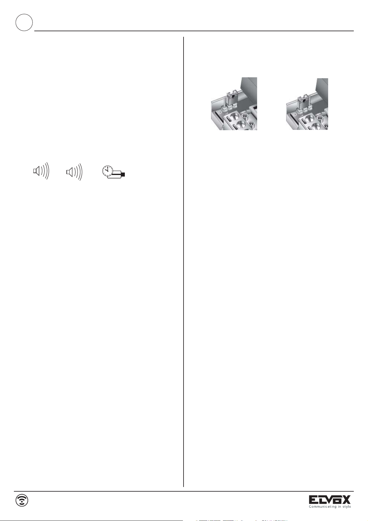
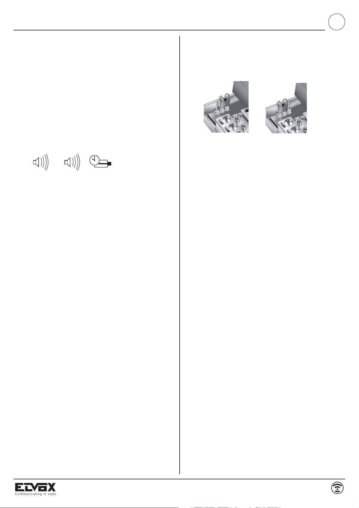
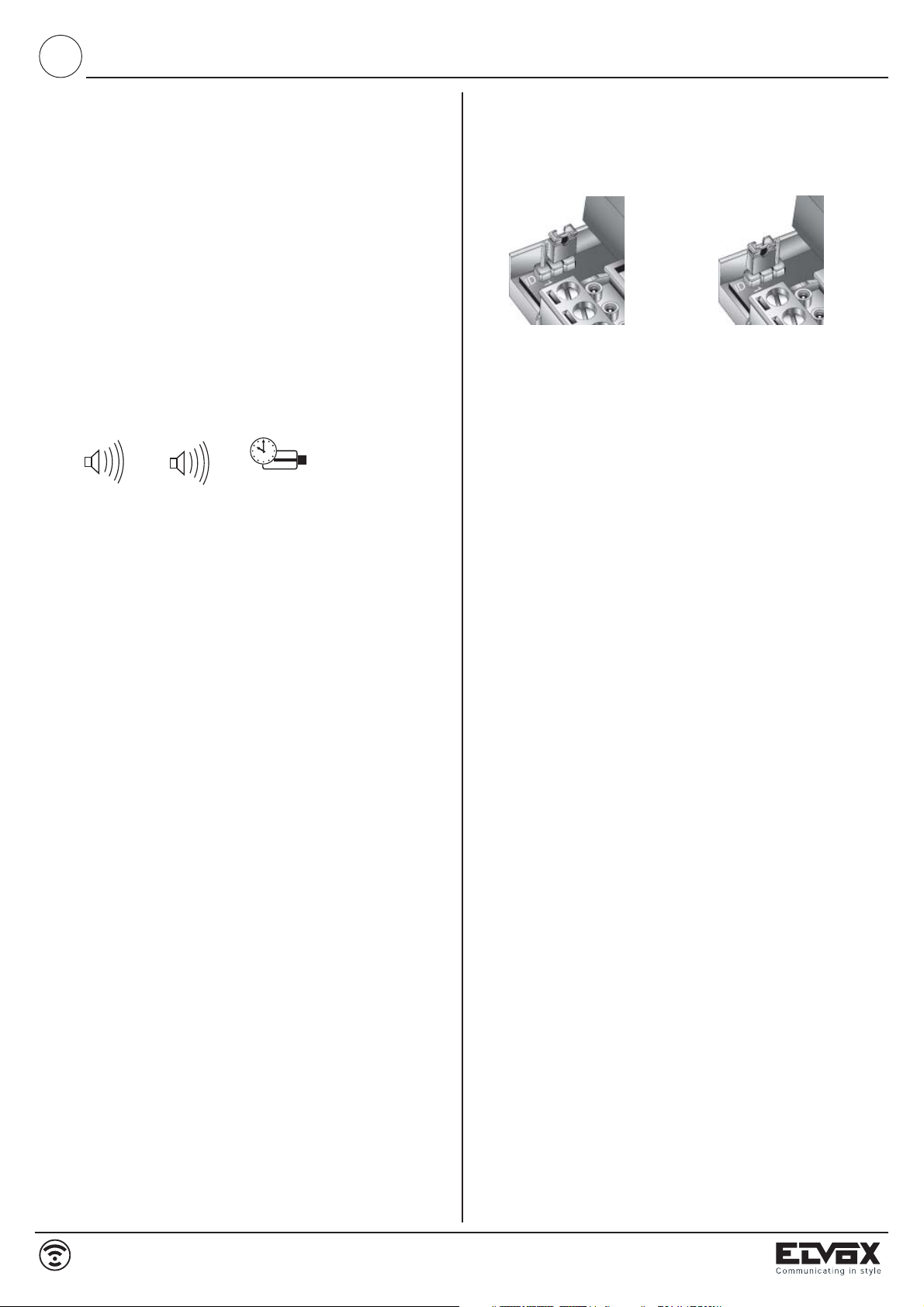
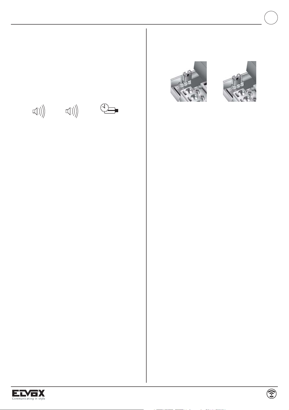
CODICE DI IDENTIFICAZIONE TARGA/POSTO ESTERNO
Quando nell’impianto ci sono più posti esterni/targhe è necessario identificare i posti esterni con un codice di identificazione diverso. Il codice di identificazione viene assegnato tramite l’inserzione dei ponticelli nei contatti
come indicato in figura.
TEMPI DI FUNZIONAMENTO
Il monitor, il posto esterno, la serratura e servizi ausiliari devono funzionare
con i seguenti cicli di intermittenza.
Ciclo accensione monitor e posto esterno:
90 secondi massimi acceso, 90 secondi spento
Ciclo serratura:
1 secondo massimo attiva, 5 secondi disattiva
Ciclo servizi ausiliari
90 secondi massimi attivo, 90 secondi disattivo.
COLLEGAMENTI
Videokit ART. 68../R e 68../R2 (in bianco e nero)
I due fili di collegamento tra alimentatore e monitor possono essere invertiti tra loro.
- Il cavo consigliato per il collegamento dei citofoni/videocitofoni con
l’alimentatore e la targa è il 732H (2x0,75 mm² twistato) o 732I (2x1 mm²
twistato). Se il cavo utilizzato non è quello indicato non si garantisce
quanto descritto nel seguito.
- L'impianto è garantito per un buon funzionamento con una distanza massima tra alimentatore e monitor di 100 m.
- L'impianto è garantito per un buon funzionamento con una distanza massima tra alimentatore e posto esterno di 100 m.
- Comunque la distanza complessiva tra monitor e posto esterno non deve
essere superiore a 120 m.
- La serratura elettrica collegata all'impianto dovrà avere un assorbimento
massimo di 1A alla tensione di 12V.
- Disturbi o scariche elettriche possono ripercuotersi sul buon
funzionamento delle apparecchiature.
Videokit ART. 68../RC e 68../RC2 (a colori)
I due fili di collegamento tra alimentatore e monitor possono essere invertiti tra loro.
- Il cavo consigliato per il collegamento dei citofoni/videocitofoni con
l’alimentatore e la targa è il 732H (2x0,75 mm² twistato) o 732I (2x1 mm²
twistato). Se il cavo utilizzato non è quello indicato non si garantisce
quanto descritto nel seguito.
- L'impianto è garantito per un buon funzionamento con una distanza massima tra alimentatore e monitor di 50 m.
- L'impianto è garantito per un buon funzionamento con una distanza massima tra alimentatore e posto esterno di 50 m.
- Comunque la distanza complessiva tra monitor e posto esterno non deve
essere superiore a 60 m.
- La serratura elettrica collegata all'impianto dovrà avere un assorbimento
massimo di 1A alla tensione di 12V.
- Disturbi o scariche elettriche possono ripercuotersi sul buon
funzionamento delle apparecchiature.
REGOLAZIONI POSTO ESTERNO Art. 68TU/930
Sul retro della posto esterno sono presenti le seguenti regolazioni:
CARATTERISTICHE TECNICHE DEL POSTO ESTERNO Art. 68TU/930
- Temperatura di funzionamento da -5° a + 45° C.
- Morsettiera per il collegamento estraibile.
- Pulsante di chiamata videocitofono.
- Uscita per comando faretto illuminazione tramite relè Art. 170/101.
- Comando apriporta locale con la stessa temporizzazione del comando da
videocitofono (1 secondo, fisso non regolabile).
- Alimentazione data dal bus.
- Dimensioni di ingombro massime 80x120x25 mm.
DESCRIZIONE
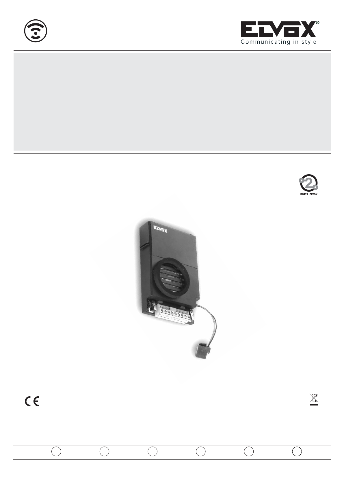
L’art. 68TU/930 è un posto esterno audio da utilizzare per videokit “2 Fili”,
dotato di un ingresso che permette il collegamento di una telecamera tipo
TVCC esterna. Può essere installato solo su targhe Art. 88V1/SP, 88V2/SP
della serie 8000.
*
Page 3
GB
3/16
68TU/930
ENTRANCE PANEL/SPEECH UNIT
IDENTIDFICATION CODE.
If more speech units/entrance panels are installed on the building it is necessary to identify the speech units with a different code. The identification
code is assigned by inserting the jumpers in the contacts as shown on the
figure.
2nd speech unit IT=11st speech unit IT=0
External
volume
Speech unit
activation time
Internal
volume
SPEECH UNIT TERMINALS TYPE 68TU/930
CL, M) Connection for relay type 170/101 for additional floodlight.
It is activated for the time the speech unit is on.
CA, M) Connection for additional lock push-button.
PA, M) Connection for "open door" sensor. The sensor must be a normally
open contact which closes when the door is open.
B1, B2) BUS line
S-, S+) Output for electric lock supply voltage (12V ).
V, M) Video signal connection of an outdoor camera.
*
The panel supplies a current peak IT> 1A for 10 mS, followed by a hold
current IM= 200mA for the entire duration of the lock control.
*
OPERATING DWELL TIME
The monitor, speech unit, door lock and auxiliary services mut operate according to the following intermittent cycles.
Monitor and speech unit activation cycle:
max. 90 seconds activated, 90 seconds deactivated
Door lock cycle:
max. 1 second activated, 5 seconds deactivated
Auxiliary service cycle:
max. 90 seconds activated, 90 seconds deactivated
CONNECTIONS
Videokit Type 68../R and 68../R2 in black and white.
The two connecting wires between power supply and monitor can be inverted.
- The advised cable for the connection of the interphones/monitors with the
power supply and the entrance panel is type 732H (2x0,75 mm² twisted
pair) or 732I (2x1 mm² twisted pair). If the cable used is other than the advised one we cannot guarantee what is written underneath.
- The installation is guaranted for a good operation with 100 m maximum
distance from the power supply to the monitor.
- In any case the maximum distance between the speech unit and the monitor must not exceed 120 m.
- The electric lock connected to the installation must have a maximum of
1A power consumption with 12V voltage.
- Humming sounds or electrical discharges may affect the appliance good
operation.
Videokit type 68../RC and 68../RC2 (colour)
The two connecting wires between power supply and monitor can be inverted.
- The advised cable for the connection of the interphones/monitors with the
power supply and the entrance panel is type 732H (2x0,75 mm² twisted
pair) or 732I (2x1 mm² twisted pair). If the cable used is other than the advised one we cannot guarantee what is written underneath
- The installation is guaranted for a good operation with 50 m maximum distance from the power supply to the monitor.
- The installation is guaranted for a good operation with 50 m maximum distance from the power supply to the speech unit.
- In any case the maximum distance between the speech unit and the monitor must not exceed 60 m.
- The electric lock connected to the installation must have a maximum of
1A power consumption with 12V voltage.
- Humming sounds or electrical discharges may affect the appliance good
operation.
SPEECH UNIT TECHNICAL FEATURES TYPE 68TU/930
- Operating temperature -5° +45°C
- Removable terminal block
- Monitor call push-button.
- Output for control of lighting floodlight by relay type 170/101
- Lock release control with same timing as command from the monitor (1
second, not adjustable).
- Supply voltage from the bus.
- External dimensions: 80x120x25 mm.
SPEECH UNIT ADJUSTMENTS TYPE 68TU/930
On the speech unit rear side find the following adjustments:
DESCRIPTION
Type 68TU/930 is an audio speech unit to be used for 2-Wire video kits.
It is equipped with an input which allows the connection of an outdoor CCTV
camera. It can only be installed on entrance panels type 88V1/SP and
88V2/SP from the 8000 series.
Page 4
F
68TU/930
4/16
Volume
externe
Temps activation
poste externe
2ème poste externe IT=1
1ère poste externe IT=0
BORNES DE LA POSTE EXTERNE ART. 68TU/930
CL, M) Raccordement pour relais Art. 170/101 pour projecteur éclairage
supplémentaire. Il est activé pour la période d'enclenchement de la
poste externe.
CA,M) Raccordement pour poussoir ouvre-porte supplémentaire.
PA, M) Raccordement pour senseur "porte ouverte", le senseur doit avoir
un contact normalement ouverte qui se ferme lorsque la porte est
ouverte.
B1, B2) Ligne BUS
S-, S+) Sortie pour alimentation gâche électrique (12V )
V, M) Connexion signal vidéo d'une caméra extérieure.
*
CODE D’IDENTIFICATION PLAQUE DE RUE/CAMERA
Lorsque dans une intallation il y a plusieurs poste externes/plaques de rue
il faut mieux identifier la camera avec un code différent des autres. Le code
d’indentification est assigné au moyen de l’insertion des pontets dans les
contacts selon la figure.
Volume
interne
La plaque fournit un pic de courant IT> 1A pendant 10 mS qui est suivi
d'un courant de maintien I
M= 200mA pendant toute la durée de la com-
mande serrure.
*
TEMPS DE FONCTIONNEMENT:
Le moniteur, la poste externe, la gâche et les services auxiliaires doivent
fonctionner selon les cycles d'intermittance suivants:
Cycle enclenchement moniteur et poste externe
90 secondes (max) activé, 90 secondes désactivé
Cycle gâche
1 seconde activé (max), 5 secondes désactivé
Cycle services auxiliaires
90 secondes activé (max), 90 secondes déactivé
RACCORDEMENTS
Kit vidéo Art. 68../R et 68../R2 en blanc/noir
Les deux fils de raccordmenet entre l'alimentation et le moniteur peuvent
être intervertis entre eux.
- Le câble conseillé pour le raccordement des postes
d’appartement/moniteurs avec l’alimentation et la plaque de rue est l’Art.
732H (2x1 mm² paire twistée) ou 732I (2x0,75 mm² paire twistée). Si l’on
utilise un câble différent de celui conseillé on ne peut pas assurer ce qui
est écrit ci-dessous.
- L'installation est garantie pour un bon fonctionnement avec une distance
maximum entre l'alimentation et le monitor de 100 m.
- La distance totale entre moniteur et poste externe ne doit pas être supérieure à 120 m.
- La gâche électrique connectée à l'installation doit avoir une absorption
maximum d' 1A à la tension de 12V.
- Bourdonnements et décharges électriques peuvent influencer le bon fonctionnement des appareils.
Videokit Art. 68../RC et 68../RC2 (en couleurs)
Les deux fils de raccordmenet entre l'alimentation et le moniteur peuvent
être intervertis entre eux.
- Le câble conseillé pour le raccordement des postes
d’appartement/moniteurs avec l’alimentation et la plaque de rue est l’Art.
732H (2x1 mm² paire twistée) ou 732I (2x0,75 mm² paire twistée). Si l’on
utilise un câble différent de celui conseillé on ne peut pas assurer ce qui
est écrit ci-dessous.
- L'installation est garantie pour un bon fonctionnement avec une distance
maximum entre l'alimentation et le monitor de 50 m.
L'installation est garantie pour un bon fonctionnement avec une distance
maximum entre l'alimentation et poste externe de 50 m.
- La distance totale entre moniteur et poste externe ne doit pas être supérieure à 60 m.
- La gâche électrique connectée à l'installation doit avoir une absorption
maximum d' 1A à la tension de 12V.
- Bourdonnements et décharges électriques peuvent influencer le bon fonctionnement des appareils.
CARACTERISTIQUES TECHNIQUES DE LA CAMERA (ART. 68TU/930)
- Température de fonctionnement -5° + 45° C
- Éclairage porte-noms au moyen de LEDs
- Boîte de raccordement amovible
- Poussoir appel moniteur
- Sortie pour commande projecteur éclairage au moyen de relais Art.
170/101.
- Commande ouvre-porte local avec la même temporisation du moniteur (1
seconde, non réglable).
- Alimentation donnée par le bus.
- Dimensions maximum externes: 80x120x25 mm.
RÉGLAGES POSTE EXTERNE (ART. 68TU/930)
À l'arrière de la poste externe il y a le réglages suivants:
DESCRIPTION
L'art. 68TU/930 est un micro haut-parleur à utiliser pour kit vidéo “2 Fils”, équipé
d'une entrée qui permet de raccorder une caméra type CCTV extérieure. Il ne
peut être installé que les plaques de rue Art. 88V1/SP, 88V2/SP de la série 8000.
Page 5
68TU/930
5/16
D
KLEMME DER AUßENSTELLE ART. 68TU/930
CL, M) Anschluß für Relais Art. 170/101 für Zusatzscheinwerfer .
Er wird für die Aktivierungszeit der Außenstelle betätigt.
CA, M) Anschluß für Zusatztüröffnertaste.
PA, M) Anschluß für den "Tür offen"-Sensor. Der Sensor muss ein Arbeit-
kontakt haben, der schliesst sich wann die Tür geöffnet ist.
B1, B2) BUS Linie
S-, S+) Ausgang für Versorgung des elektrischen Türöffners (12V ).
V, M) Anschluss des Videosignals einer Außenkamera.
*
Exterlautstärke
Außenstelleaktivierung
Zeit
IDENTIFIZIERUNGSCODE DES(R) KLINGELTABLEAUS/AUßENSTELLE
Wenn bei der Anlage mehrere Klingeltableaus/Außenstelles eingebaut werden, ist es notwendig die Außenstelles mit untersschiedlichem Code zu
identifizieren. Die Identifizierungscode wird durch Einsetzen der Brücken in
die Kontakten wie in Abbildung gezeigt, gekoppelt.
2° Außenstelle IT=1
1° Außenstelle IT=0
Interlautstärke
Das Klingeltableau liefert eine Stromspitze IT> 1A für 10 mS, darauf folgt
ein Haltestrom Im= 200mA für die gesamte Dauer der Türschlosssteuerung.
*
BETRIEBSDAUER
Monitor, Außenstelle, Türöffner und Zusatzdienste durfen mit den folgenden Intermittierendzyklusses arbeiten.
Monitor und Außenstelle Einschaltzyklus:
Max 90 Sekunden aktiviert, 90 Sekunden deaktiviert
Türöffnerzyklus:
Max 1 Sekunden aktiviert, 5 Sekunden deaktiviert
Zusatzdienstzyklus:
Max 90 Sekunden aktiviert, 90 Sekunden deaktiviert.
ANSCHLÜSSE
Videoset Art. 68../R und 68../R2 in Schwarz/Weiss
Die zwei Anschlussdrähte zwischen dem Netzgerät und dem Monitor können einander ausgetauscht werden.
- Das empfehltete Kabel für den Anschluss der Haustelefonen/Monitoren
mit dem Netzgerät und dem Klingeltableau ist Art. 732H (2x0,75 mm² Twistpaar) oder 732I (2x1 mm² Twistpaar) . Soll ein anderes Kabel verwendet werden, so können wir nicht was untergeschrieben ist gewährleiste
- Die Anlage gewährleistet einen guten Betrieb mit 100m maximum Abstand zwischen Netzgerät und Monitor .
- Auf jeden Fall kann der Totalabstand zwichen Netzgerät und Außenstelle
120m nicht überschreiten.
- Der an der Anlage angeschlossene elektrische Türöffner darf max 1A
auf 12V Spannung betragen.
- Störungen und elektrische Entladungen können den optimalen Betrieb
der Anlagen beeinflüssen.
Videoset Art. 68../RC und 68../RC2 (Farbe)
Die zwei Anschlussdrähte zwischen dem Netzgerät und dem Monitor können einander ausgetauscht werden.
- Das empfehltete Kabel für den Anschluss der Haustelefonen/Monitoren
mit dem Netzgerät und dem Klingeltableau ist Art. 732H (2x0,75 mm² Twistpaar) oder 732I (2x1 mm² Twistpaar) . Soll ein anderes Kabel verwendet werden, so können wir nicht was untergeschrieben ist gewährleisten.
- Die Anlage gewährleistet einen guten Betrieb mit 50m maximum Abstand
zwischen Netzgerät und Monitor.
- Die Anlage gewährleistet einen guten Betrieb mit 50m maximum Abstand
zwischen Netzgerät und Außenstelle.
- Auf jeden Fall kann der Totalabstand zwichen Netzgerät und Außenstelle
60m nicht überschreiten.
- Der an der Anlage angeschlossene elektrische Türöffner darf max 1A
auf 12V Spannung betragen.
- Störungen und elektrische Entladungen können den optimalen Betrieb
der Anlagen beeinflüssen.
TECHNISCHE EIGENSCHAFTEN DER AUßENSTELLE (ART. 68TU/930)
- Betriebstemperatur von -5° + 45°C
- Namenschildbeleucthung durch LED
- Abnehmbares Klemmenbrett
- Monitorruftaste
- Ausgang für Beleuchtungscheinwerfer mittels Relais Art. 170/101.
- Befehl für Orttüröffner mit der gleichen Zeitregelung der Monitorbefehl
(1 Sekunden nicht verstellbar).
- Versorgung vom Bus
- Abmessungen: 80x125x25 mm.
EINSTELLUNGEN DER AUßENSTELLE ART. 68TU/930
Auf der Außenstellerückseite befinden sich die folgenden Einstellungen:
Page 6

E
68TU/930
6/16
Volumen
externo
Tiempo activación
aparato externo
Volumen
interno
BORNES DE LA APARATO EXTERNO ART. 68TU/930
CL, M) Conexionado para relé Art. 170/101 para iluminador suplementa-
rio. Se activa por el periodo de encendido de la aparato externo.
CA, M) Conexionado para pulsador abrepuerta suplementario.
PA, M) Conexionado para sensor puerta abierta. El sensor debe ser un
contacto normalmente abierto que se cierra cuando la puerta está
abierta.
B1, B2) Línea BUS
S-, S+) Salida para alimentación cerradura eléctrica (12V ).
V, M) Conexión de la señal de video de una cámara externa.
*
La placa proporciona un pico de corriente IT> 1A durante 10 mS tras
el cual sigue una corriente de mantenimiento IM= 200mA por toda la duración del mando de la cerradura.
*
CODIGO DE IDENTIFICACIÓN PLACA/APARATO EXTERNO
Cuando en una instalación hay más de una placa/aparato externo es necesario identificar las aparato externos con un código diferente. El código de
identificación viene asignado por medio de la inserción de puentes en los
contactos como indica la figura.
2da Aparato externo IT=1
1ra Aparato externo IT=0
TIEMPOS DE FUNCIONAMIENTOS
El monitor, la aparato externo, la cerradura y los servicios auxiliares deben
funcionar con los siguientes ciclos de intermitencia.
Ciclo de encendido monitor y aparato externo
90 secundos (máx) activado, 90 segundos desactivado
Ciclo cerradura:
1 segundos (máx) activado, 5 segundos desactivado
Ciclo servicios auxiliares
90 segundos (máx) activado, 90 segundos desactivado
CONEXIONADOS
Kir vídeo Art. 68../R y 68../R2 en blanco y negro.
Los dos hilos de conexión entre alimentador y monitor pueden ser invertidos entre ellos.
- El cable aconsejado para el conexionado de los teléfonos/monitores con
el alimentador y la placa es el 732H (2x0,75 mm² par twistado) o 732I
(2x1 mm² par twistado). Si viene utilizado otro cable no es posible asegurar lo que es escrito a continuación.
- Se asegura un buen funcionamiento de la instalación con una distancia
máxima entre alimentador y monitor de 100 m.
- De todos modos la distancia total entre monitor y aparato externo tendrá
que tener una absorpión máxima de 1A a la tensión de 12V.
- Interferencias o descargas eléctricas pueden influenciar el buen funcionamiento de los aparatos.
Videokit art. 68../RC y 68../RC2 (en color)
Los dos hilos de conexión entre alimentador y monitor pueden ser invertidos entre ellos.
- El cable aconsejado para el conexionado de los teléfonos/monitores con
el alimentador y la placa es el 732H (2x0,75 mm² par twistado) o 732I
(2x1 mm² par twistado). Si viene utilizado otro cable no es posible asegurar lo que es escrito a continuación.
- Se asegura un buen funcionamiento de la instalación con una distancia
máxima entre alimentador y monitor de 50 m.
- Se asegura un buen funcionamiento de la instalación con una distancia
máxima entre alimentador y aparato externo de 50 m.
- De todos modos la distancia total entre monitor y aparato externo no
debe superar los 60 m.
- De todos modos la distancia total entre monitor y aparato externo tendrá
que tener una absorpión máxima de 1A a la tensión de 12V.
- Interferencias o descargas eléctricas pueden influenciar el buen funcionamiento de los aparatos.
CARACTERÍSTICAS TÉCNICAS DE LA APARATO EXTERNO ART.
68TU/930
- Temperatura de funcionamiento - 5° + 45° C
- Iluminación tarjeta porta-nombres por medio de LEDs
- Regleta de conexiones extraíble
- Pulsador llamada monitor
- Salida para mando iluminador por medio de relé Art. 170/101
- Mando abrepuerta local con la misma temporización del mando desde el
monitor (1 segundo, no ajustable).
- Alimentación dada por el bus.
- Dimensiones máximas externas: 80x120x25 mm.
REGULACIONES APARATO EXTERNO ART. 68TU/930
Detrás de la aparato externo se encuentran las regulaciones siguientes.
DESCRIPCIÓN
El Art. 68TU/930 es un aparato externo audio que se utiliza para el videokit de
dos hilos “Due Fili”, provisto de una entrada que permite la conexión de una cámara externa tipo CCTV. Se puede instalar sólo en las placas Art. 88V1/SP,
88V2/SP de la serie 8000.
Page 7

68TU/930
7/16
P
TIEMPOS DE FUNCIONAMIENTOS
O monitor, a posto externo, o trinco e os serviços auxiliares devem funcionar com os seguintes ciclos de intermitência.
Ciclo de acendimento do monitor e posto externo.
90 segundos (máx) ligado, 90 segundos desligado
Ciclo do trinco:
1 segundos (máx) ligado, 1 segundos desligado
Ciclo serviços auxiliares
90 segundos (máx) ligado, 90 segundos desligado.
CÓDIGO DE IDENTIFICAÇÃO BOTONEIRA/POSTO EXTERNO
Quando na instalação há mais do que 1 posto externo/botoneira é necessário identificar as posto externos com um código diferente. O código de
identificação é assignado através a inserção das pontes nos contactos
come indica a figura.
2° Posto externo IT=11° Posto externo IT=0
TERMINAIS DA posto externo ART. 68TU/930
CL,M) Ligação para relé art. 170/101 para iluminador suplementar.
Activa-se pelo período de acendimento da posto externo.
CA, M) Ligação para botão abre-porta suplementar.
PA, M) Ligação para sensor "porta aberta". O sensor deve ser um contacto
normalmente aberto que fecha-se quando a porta está aberta.
B1, B2) Linha BUS
S-, S+) Saída para alimentação do trinco eléctrico (12V ).
V, M) Ligação do sinal de vídeo de uma telecâmara externa.
*
A botoneira fornece um pico de corrente IT>1A durante 10 ms após o
qual se segue uma corrente I
M
=200mA enquanto se mantém o co-
mando do trinco.
*
Volumen
externo
Tempo di activação
posto externo
Volumen
interno
LIGAÇÕES
Kit video Art. 68../R y 68I… em branco/preto.
Os dois fios de ligação entre alimentador e monitor podem ser trocados
entre si.
- O cabo aconselhado para a ligação entre os telefones/monitores com o
alimentador e a botoneira es do tipo 732H (2x0,75 mm² par twistado) ou
732I (2x1 mm² par twistado). Se utiliza-se outro cabo não pode-se assegurar o escrito a continuação.
- A instalação garante um bom funcionamento com uma distância máxima
de 100 m. entre alimentador e monitor
- De qualquer maneira a distância total entre o monitor e a posto externo
não deve superar os 120 m.
- O trinco eléctrico ligado à instalação deverá ter uma absorção máxima
de 1A à tensão de 12V.
- Disturbios o descargas eléctricas podem influir no bom funcionamento da
aparelhagem.
Videokit Art. 68../RC e 68../RC2 (a cores)
Os dois fios de ligação entre alimentador e monitor podem ser trocados
entre si.
- O cabo aconselhado para a ligação entre os telefones/monitores com o
alimentador e a botoneira es do tipo 732H (2x0,75 mm² par twistado) ou
732I (2x1 mm² par twistado). Se utiliza-se outro cabo não pode-se assegurar o escrito a continuação.
- A instalação garante um bom funcionamento com uma distância máxima
de 50 m. entre alimentador e monitor
- A instalação garante um bom funcionamento com uma distância máxima
de 50 m. entre alimentador e posto externo
- De qualquer maneira a distância total entre o monitor e a posto externo
não deve superar os 60 m.
- O trinco eléctrico ligado à instalação deverá ter uma absorção máxima
de 1A à tensão de 12V.
- Disturbios o descargas eléctricas podem influir no bom funcionamento da
aparelhagem
REGULAÇÕES DA POSTO EXTERNO ART. 68TU/930
Detrás da posto externo há as regulações seguintes:
CARACTÉRISTICAS TÉCNICAS DA POSTO EXTERNO ART. 68TU/930
- Temperatura de funcionamento: -5°C +45°C
- Iluminação do cartão porta-nomes através de LED.
- Régua de ligação extraível
- Botão de chamada monitor
- Saída para comando iluminador por meio do relé Art. 170/101.
- Comando do trinco local com a mesma temporização do comando do
monitor (1 segunda, não ajustável).
- Alimentação dada pelo bus.
- Dimensões: 80x120x25 mm.
DESCRIÇÃO
O Art. 68TU/930 é um posto externo áudio a utilizar para o kit vídeo “2 Fili”,
dotado de uma entrada que permite a ligação de uma telecâmara tipo
TVCC externa. Só pode ser instalado nas botoneiras Art. 88V1/SP,
88V2/SP da série 8000.
Page 8

68TU/930
8/16
2° pulsante
2nd push-button
2ème bouton-poussoir
zweien Taste
2er pulsador
2° botão
Microfono
Microphone
Microphone
Mikrofon
Micrófono
Micrófono
Fig. 1
Fig. 2
1° pulsante
1nd push-button
1ème bouton-poussoir
ersten Taste
1er pulsador
1° botão
LED
di illuminazione cartellino portanomi
LEDs lighting up the name-tag holder
Leds für die Namensschildbeleuchtung
LED d'éclairage de l'étiquette porte-noms
Leds de iluminación del tarjetero
LEDs de iluminação do cartão porta-nomes
Page 9

68TU/930
9/16
INSTALLAZIONE TARGA Art. 88V1/SP (ART. 88V2/SP)
Fissare la scatola da esterno della targa su una scatola da incasso a 3 moduli
oppure a parete con tasselli.
Fig. 3 La figura mostra l’in sie me dei com po nen ti la targa:
A - Placca frontale
B - Posto esterno
C - Scatola da esterno parete
D - Cacciavite
E
- Morsettiera estraibile per il col le ga men to del posto esterno.
Effettuare i col le ga men ti del posto esterno e della serratura a mez zo della
morsettiera estraibile (par ti co la re “E” di Fig. 3). Dopo aver effettuato il col lau do si procede al fis sag gio della placca uti liz zan do la vite di sicurezza a
mezzo di un cacciavite (par ti co la re “D” di Fig. 3).
VIDEO ENTRANCE PANEL INSTALLATION ART. 88V1/SP (TYPE
88V2/SP)
Before installing choose location for camera entrance panel so that it is protected from direct light (sun, car headlights, etc.) as this may affect the quality of the picture and may damage the camera. The subject to be framed
must be lighted from the front to avoid frames with backlight.
Fig. 3 The figure shows the panel components
A - Front plate
B - Speech unit
C - Surface wall-mounted back box
D - Screwdriver
E - Removable terminal block for speech unit connection.
Carry out the speech unit and door lock connections by means of the removable terminal block (detail "E", Fig. 3). After the final test fix the plate using
the security screw and the screwdriver (detail "D", Fig. 3).
INSTALLATION PLAQUE POUR PORTIER VIDÉO ART. 88V1/SP (ART.
88V2/SP)
Au moment de l'installation il vaut mieux choisir la position de la plaque de
rue de façon que la plaque ne soit pas frappée directement par de faisseaux lumineux (soleil, phares, d'auto, etc.). Le sujet à prendre doit être illuminé en face pour éviter la prise de vue en contre-jour.
Fig. 3
A - Plaque frontale
B - Poste externe
C - Boîtier pour montage mural en saillie
D - Turnevis
E - Bornier amovible pour le raccordement du poste externe
Effectuer les raccordements du poste externe et de la gâche au moyen du
bornier amovible (détail " E ", Fig. 3). Après avoir effectué l'essai final, on
procède à la fixation de la plaque en utilisant la vis de sécurité et d'un turnevis (détail "D ", Fig. 3).
EINBAU DES KLINGELTABLEAUS FÜR VIDEO-TÜRSPRECHANLAGE
ART. 88V1/SP (ART. 88V2/SP)
Bei der Montage achten Sie darauf, daß die Video-Türsprechstelle von direkten Licht (Sonne, Scheinwerfer, etc.) geschützt ist. Dies könnte die Bildqualität beeintrachtigen oder den CCD-Sensor zerstören.
Abb. 3 Die Abbildung zeigt die Bestandteile des Klingeltableaus
A - Frontplatte
B - Außenstelle
C - Ap-Gehäuse
D - Schraubenzieher
E - Abnehmbares Klemmenbrett für den Außenstelleanschluss
Die Außenstelle und Turöffneranschlüsse mittels der abnehmbaren Klemmenleiste durchführen (Detail "E", Abb. 3). Nach der Überprüfung unter
Verwendung der Sicherheitschrauben und von einem Schraubenzieher befestigen (Detail "D", Abb. 3).
INSTALACIÓN PLACA PARA PORTERO VÍDEO ART. 88V1/SP (ART.
88V2/SP)
El efectuar la instalación es oportuno escoger la posición de la cámara de
manera que se evite fuentes luminosas directas (por ejemplo sol, focos,
lámparas etc.). La persona debe ser iluminada frontalmente para evitar la
imagen en contraluz.
Fijar la caja de superfice de la placa sobre una caja de empotre de 3 módulos o a la pared con tacos.
Fig. 3 La figura muestra el conjunto de los componentes de la placa:
A - Plancha frontal
B - Aparato externo
C - Caja de superficie
D - Destornillador
E -
Regleta de conexiones extraíble para el conexionado de
aparato externo.
Efectuas las conexiones de aparato externo y de la cerradura por medio de
la regleta de conexiones extraíble (particular " E ", Fig. 3). Después de
haber efectuado la prueba final proceder a la fijación de la placa utilizando
el tornillo de seguridad y de un destornillador (particular " D ", Fig. 3).
INSTALAÇÃO DA BOTONEIRA DE VIDEO PORTEIRO ART. 88V1/SP
(ART. 88V2/SP)
No acto da instalação é importante escolher a posição da câmara de modo
a que não seja a incidência directa de fontes luminosas (sol, lampão, faróis
de caros etc.). O sujeito a ser focado pela telecâmara deve ser iluminado
frontalmente de modo a evitar a focagem em contraluz. A telecâmara é
dotada dum emissor de infravermelhos que permite en caso de ausencia
de iluminação focar o sujeito a cerca de um metro de distância. Durante a
instalação deve ser aplicada uma proteção anti-chuva por cima da telecâmara.
Fixar a caixa de montagem saliente da botoneira numa caixa de emebeber
de 3 módulos ou com calhas para montagem saliente.
Fig. 3 A figura mostra o conjunto dos componentes da botoneira:
A - Placa frontal
B - Posto externo com posto externo
C - Caixa para montagem saliente
D - Parafusos
E - Régua de ligação extraível para a ligação da telecâmara.
Efectuar as ligações do posto externo e do trinco por meio da régua extraível (particular "E", Fig. 3). Após o controle ser efectuado continuar com a
fixação da botoenira utilizando o duma chave de parafusos (particular "D",
Fig. 3).
Page 10

68TU/930
10/16
A
B
C
E
D
Fig. 3
Page 11

68TU/930
11/16
SEZIONE CONDUTTORI CONSIGLIATA PER I DUE FILI
CONDUCTOR SECTION ADVISED FOR THE TWO WIRES
SECTION DES CONDUCTEURS CONSEILLÉE POUR LES DEUX FILS
LEITERQUERSCHNITT EMPFEHLT FÜR DIE ZWEI DRÄHTE
SECCIÓN CONDUCTORES ACONSEJADA PARA LOS DOS HILOS
SECÇÃO CONDUCTORES ACONSELHADA PARA OS DOIS FIOS
VIDEOKIT Art. 68../R e 68../R2 (IN BIANCO E NERO)
VIDEOKIT Type 68../R AND 68../R2 IN BLACK AND WHITE.
KIT VIDÉO Art. 68../R ET 68../R2 EN BLANC/NOIR.
VIDEOSET Art. 68../R UND 68../R2 IN SCHWARZ/WEISS.
KIR VÍDEO Art. 68../R Y 68../R2 EN BLANCO Y NEGRO.
KIT VIDEO Art. 68../R Y 68I… EM BRANCO/PRETO.
DUE FILI DI SEZIONE MINIMA 0,75 PER 100 metri MASSIMI
TWO WIRES WITH MINIMUM SECTION OF 0.75 FOR A MAXIMUM OF 100 METRES.
DEUX FILS AVEC SECTION MINIMALE DE 0,75 POUR UN MAXIMUM DE 100 MÈTRES.
ZWEI DRÄHTE MIT MINIMUM QUERSCHNITT VON 0.75 FÜR 100 M. MAX.
DOS HILOS DE SECCIÓN MÍNIMA 0,75 PARA UN MÁXIMO DE 100 METROS.
DOIS FIOS DE SECÇÃO MÍNIMA 0,75 PARA UM MÁXIMO DE 100 METROS.
VIDEOKIT ART. 68../RC E 68../RC2 (A COLORI)
VIDEOKIT TYPE 68../RC AND 68../RC2 (COLOUR)
VIDEOKIT ART. 68../RC ET 68../RC2 (EN COULEURS)
VIDEOSET ART. 68../RC UND 68../RC2 (FARBE)
VIDEOKIT ART. 68../RC Y 68../RC2 (EN COLOR)
VIDEOKIT ART. 68../RC E 68../RC2 (A CORES)
CAVO TWISTATO ART. 732H O 732I PER 60 metri MASSIMI
TWISTED CABLE ART. 732H OR 732I FOR A MAXIMUM OF 60 METRES
CÂBLE TWISTÉ ART. 732H OU 732I POUR UN MAXIMUM DE 60 MÈTRES
“TWISTED“ KABEL ART. 732H ODER 732I FÜR 60 METER (MAX).
CABLE TWISTADO ART. 732H O 732I PARA UN MÁXIMO DE 60 METROS.
CABO TWISTADO ART. 732H OU 732I PARA UM MÁXIMO DE 60 METROS.
*
SCHEMA DI COLLEGAMENTO - WIRING DIAGRAM - SCHÉMAS DE RACCORDEMENENT
SCHALTPLAN - ESQUEMA DE CONEXIONADO - ESQUEMA DE LIGAÇÃO
Page 12

68TU/930
12/16
SCHEMA DI COLLEGAMENTO KIT VIDEO 2 FILI
WIRING DIAGRAM FOR 2 WIRES VIDEO KIT
SCHÉMAS DE RACCORDEMENENT POUR KIT VIDÉO 2 FILS
SCHALTPLAN FÜR VIDEO-TÜRSPRECHANLAGE 2 DRAHT KIT
ESQUEMA DE CONEXIONADO KIT VÍDEO 2 HILOS
ESQUEMA DE LIGAÇÃO KIT DE VIDEO 2 FIOS
MONITOR
MONITEUR
Art. 6009+62I8+6145
Art. 6009/C+62I8+6145
ALIMENTATORE
POWER SUPPLY
ALIMENTATION
NETGERÄT
ALIMENTADOR
Art. 6922
RETE
MAINS
RÉSEAU
NETZ
RED
REDE
N° SI610e
*
*
ALIMENTATORE
POWER SUPPLY
ALIMENTATION
NETGERÄT
ALIMENTADOR
Art. 6582
RELE’
RELAY
RELAIS
ART. 170/101
RETE
MAINS
RÉSEAU
NETZ
RED
REDE
ILLUMINAZIONE ZONA DI RIPRESA
COVERAGE ZONE LIGHTING
ÉCLAIRAGE ZONE DE PRISE DE VUE.
AUFNAMENZONEBELEUCHTUNG
ILUMINACIÓN DE LA ZONA DE CAPTACITÓN
ILUMINACIÓN DA ZONA DE FOCAGEM
CARICO MASSIMO
MAX LOAD
CHARGE MAXIMUM
MAXIMUM LAST
CARGA MÁXIMA
3A - 230V ~
A - TARGA AUDIO ART. 88V1/SP
B - POSTO ESTERNO ART. 68TU/930
C - SERRATURA ELETTRICA 12V~ 1A
D - PULSANTE PER CHIAMATA FUORIPORTA
E - COMANDO APRIPORTA
F - SENSORE PORTA APERTA
L - PULSANTE PER AUTOINSERIMENTO
M - TELECAMERA TVCC
A - AUDIO ENTRANCE PANEL TYPE 88V1/SP
B - SPEECH UNIT ART. 68TU/930
C - 12V ELECTRIC LOCK
D - PUSH-BUTTON FOR OUTDOOR CALL
E - LOCK RELEASE CONTROL
F - OPEN DOOR SENSOR
L - PUSH-BUTTON FOR THE SELFACTIVATION
M - CCTV CAMERA
A - PLAQUE DUE RUE AUDIO ART. 88V1/SP
B - POSTE EXTERNE ART. 68TU/930
C - GÂCHE ÉLECTRIQUE 12V ~
D - POUSSOIR POUR APPEL PORTE PALIÈRE
E - COMMANDE OUVRE PORTE
F - SENSEUR PORTE OUVERTE
L - BOUTON-POUSSOIR POUR L'AUTOACTIVATION
M - CAMÉRA TVCC
A - AUDIO-KLINGELTABLEAU ART. 88V1/SP
B - AUSSENSTELLE ART. 68TU/930
C - ELEKTRISCHES TÜRSCHLOSS 12V ~
D - WOHNTÜRRUFTASTE
E - TÜRÖFFNUNGSSTEUERUNG
F - SENSOR FÜR "TÜR OFFEN"
L - TASTE FÜR DIE SELBSTEINSCHALTUNG
M - TVCC KAMERA
A - PLACA AUDIO ART. 88V1/SP
B - APARATO EXTERNO ART. 68TU/930
C - CERRADURA ELÉCTRICA 12V ~ 1A
D - PULSADOR LLAMADA PUERTA APARTAMIENTO
E - BELEUCHTUNGSLED DES NAMENSCHILDS
F - MANDO ABREPUERTA
L - PULSADOR PARA LA AUTOACTIVACIÓN
M - CÁMARA TVCC
A - BOTONERIA AUDIO ART. 88V1/SP
B - POSTO EXTERNO ART. 68TU/930
C - TRINCO ELÉCTRICO 12V ~ 1A
D - BOTÃO PARA CHAMADA NO PATAMAR
E - COMANDO ABREPORTA
F - SENSOR "PORTA ABERTA"
L - BOTÃO PARA A AUTOACTIVAÇÃO
M - TELECÂMARA TVCC
RETE-MAINS
RÉSEAU-NETZ
RED-REDE
1
2
4
8
L
4
5
9
6S
10
6P
11
-
12
+
13
D
+
-
1C
VIDEO
N° 1
CH1=
RC
PRI
342515
+I-+U
ACBD
PRI
28V0
B221B1
+T
-
M
V
M
S+
S-
B
IT=0
B1
B2
M
PA
CA
V
CL
A
E
F
C
Page 13

68TU/930
13/16
N° SI610d
ALIMENTATORE
POWER SUPPLY
ALIMENTATION
NETGERÄT
ALIMENTADOR
Art. 6922
*
*
MONITOR
MONITEUR
Art. 6009+62I8+6145
Art. 6009/C+62I8+6145
MONITOR
MONITEUR
Art. 6009+62I8+6145
Art. 6009/C+62I8+6145
RETE
MAINS
RÉSEAU
NETZ
RED
REDE
ILLUMINAZIONE ZONA DI RIPRESA
COVERAGE ZONE LIGHTING
ÉCLAIRAGE ZONE DE PRISE DE VUE.
AUFNAMENZONEBELEUCHTUNG
ILUMINACIÓN DE LA ZONA DE CAPTACITÓN
ILUMINACIÓN DA ZONA DE FOCAGEM
RETE-MAINS
RÉSEAU-NETZ
RED-REDE
ALIMENTATORE
POWER SUPPLY
ALIMENTATION
NETGERÄT
ALIMENTADOR
Art. 6582
RELE’
RELAY
RELAIS
ART. 170/101
CARICO MASSIMO
MAX LOAD
CHARGE MAXIMUM
MAXIMUM LAST
CARGA MÁXIMA
3A - 230V ~
SCHEMA DI COLLEGAMENTO KIT VIDEOCITOFONO BIFAMILIARE CON UNA TARGA ESTERNA A DUE PULSANTI
WIRING DIAGRAM FOR TWIN RESIDENCE VIDEOKIT WITH ONE 2 PUSH-BUTTON ENTRANCE PANEL
SCHÉMA DE RACCORDEMENT POUR KIT VIDÉO POUR VILLA BIFAMILIALE AVEC UNE PLAQUE DE RUE Á DEUX
BOUTONS- POUSSOIRS
SCHLALTPLAN FÜR ZWEI FAMILIENHÄUSER VIDEO-SET MIT EINEM 2-TASTE-KLINGELTABLEAU
ESQUEMA DE CONEXIONADO PARA KIT VIDEO BIFAMILIAR CON UNA PLACA CON DOS PULSADORES
ESQUEMA DE LIGAÇÃO PARA KIT VIDEO BIFAMILIAR COM UMA BOTONEIRA COM DOIS BOTÕES
A - TARGA AUDIO O VIDEO ART. 88V2/SP
B - POSTO ESTERNO ART. 68TU/930
C - SERRATURA ELETTRICA 12V~ 1A
D - PULSANTE PER CHIAMATA FUORIPORTA
E - COMANDO APRIPORTA
F - SENSORE PORTA APERTA
L - PULSANTE PER AUTOINSERIMENTO
M - TELECAMERA TVCC
A - AUDIO OR VIDEO ENTRANCE PANEL TYPE 88V2/SP
B - SPEECH UNIT ART. 68TU/930
C - 12V ELECTRIC LOCK
D - PUSH-BUTTON FOR OUTDOOR CALL
E - LOCK RELEASE CONTROL
F - OPEN DOOR SENSOR
L - PUSH-BUTTON FOR THE SELFACTIVATION
M - CCTV CAMERA
A - PLAQUE DUE RUE AUDIO OU VIDÉO ART. 88V2/SP
B - POSTE EXTERNE ART. 68TU/930
C - GÂCHE ÉLECTRIQUE 12V ~
D - POUSSOIR POUR APPEL PORTE PALIÈRE
E - COMMANDE OUVRE PORTE
F - SENSEUR PORTE OUVERTE
L - BOUTON-POUSSOIR POUR L'AUTOACTIVATION
M - CAMÉRA TVCC
A - AUDIO ODER VIDEO-KLINGELTABLEAU ART. 88V1/SP
B - AUSSENSTELLE ART. 68TU/930
C - ELEKTRISCHES TÜRSCHLOSS 12V ~
D - WOHNTÜRRUFTASTE
E - TÜRÖFFNUNGSSTEUERUNG
F - SENSOR FÜR "TÜR OFFEN"
L - TASTE FÜR DIE SELBSTEINSCHALTUNG
M - TVCC KAMERA
A - PLACA AUDIO O VIDEO ART. 88V2/SP
B - APARATO EXTERNO ART. 68TU/930
C - CERRADURA ELÉCTRICA 12V ~ 1A
D - PULSADOR LLAMADA PUERTA APARTAMIENTO
E - BELEUCHTUNGSLED DES NAMENSCHILDS
F - MANDO ABREPUERTA
L - PULSADOR PARA LA AUTOACTIVACIÓN
M - CÁMARA TVCC
A - BOTONERIA AUDIO OU VIDEO ART. 88V2/SP
B - POSTO EXTERNO ART. 68TU/930
C - TRINCO ELÉCTRICO 12V ~ 1A
D - BOTÃO PARA CHAMADA NO PATAMAR
E - COMANDO ABREPORTA
F - SENSOR "PORTA ABERTA"
L - BOTÃO PARA A AUTOACTIVAÇÃO
M - TELECÂMARA TVCC
+
-
RC
1C
342515
1
2
4
4
8
L
N° 2 N° 1
9
10
11
12
13
VIDEO
5
6S
6P
-
+
DD
N° 1
CH1=
CH2=
N° 2
1
4
2
8
4
5
6S
6P
-
+
9
10
11
12
13
L
VIDEO
+I-+U
ACBD
-
PRI
28V0
B221B1
PRI
+T
M
V
M
S+
B
IT=0
SB1
B2
PA
CA
CL
M
V
E
A
F
C
Page 14

68TU/930
14/16
ALIMENTATORE
POWER SUPPLY
ALIMENTATION
NETGERÄT
ALIMENTADOR
Art. 6922
*
*
MONITOR
MONITEUR
Art. 6009+62I8+6145
Art. 6009/C+62I8+6145
ALIMENTATORE
POWER SUPPLY
ALIMENTATION
NETGERÄT
ALIMENTADOR
Art. 6582
RELE’
RELAY
RELAIS
ART. 170/101
CARICO MASSIMO
MAX LOAD
CHARGE MAXIMUM
MAXIMUM LAST
CARGA MÁXIMA
3A - 230V ~
RETE
MAINS
RÉSEAU
NETZ
RED
REDE
ILLUMINAZIONE ZONA DI RIPRESA
COVERAGE ZONE LIGHTING
ÉCLAIRAGE ZONE DE PRISE DE VUE.
AUFNAMENZONEBELEUCHTUNG
ILUMINACIÓN DE LA ZONA DE CAPTACITÓN
ILUMINACIÓN DA ZONA DE FOCAGEM
N° SI610f
SCHEMA DI COLLEGAMENTO KIT VIDEOCITOFONO CON DUE TARGHE ESTERNE E UN MONITOR
WIRING DIAGRAM FOR VIDEO ENTRANCE PANEL KIT WITH TWO EXTERNAL ENTRANCE PANELS AND ONE MONITOR
SCHÉMAS DE RACCORDEMENENT POUR KIT PORTIER VIDÉO AVEC DEUX PLAQUES DE RUE ET UN MONITEUR
SCHALTPLAN FÜR EINFAMILIENHÄUSER VIDEO-TÜRSPRECHANLAGEN MIT ZWEI
KLINGELTABLEAUS UND EIN MONITOR
ESQUEMA DE CONEXIONADO KIT VÍDEO MONOFAMILIAR CON 2 PLACAS EXTERNAS Y UN MONITOR
ESQUEMA DE LIGAÇÃO KIT DE VIDEO PORTEIRO MONOFAMILIAR COM 2 BOTONEIRAS EXTERNAS E UM MONITOR
RETE-MAINS
RÉSEAU-NETZ
RED-REDE
A - TARGA AUDIO ART. 88V1/SP
B - POSTO ESTERNO ART. 68TU/930
C - SERRATURA ELETTRICA 12V~ 1A
D - PULSANTE PER CHIAMATA FUORIPORTA
E - COMANDO APRIPORTA
F - SENSORE PORTA APERTA
L - PULSANTE PER AUTOINSERIMENTO
M - TELECAMERA TVCC
A - AUDIO ENTRANCE PANEL TYPE 88V1/SP
B - SPEECH UNIT ART. 68TU/930
C - 12V ELECTRIC LOCK
D - PUSH-BUTTON FOR OUTDOOR CALL
E - LOCK RELEASE CONTROL
F - OPEN DOOR SENSOR
L - PUSH-BUTTON FOR THE SELFACTIVATION
M - CCTV CAMERA
A - PLAQUE DUE RUE AUDIO ART. 88V1/SP
B - POSTE EXTERNE ART. 68TU/930
C - GÂCHE ÉLECTRIQUE 12V ~
D - POUSSOIR POUR APPEL PORTE PALIÈRE
E - COMMANDE OUVRE PORTE
F - SENSEUR PORTE OUVERTE
L - BOUTON-POUSSOIR POUR L'AUTOACTIVATION
M - CAMÉRA TVCC
A - AUDIO-KLINGELTABLEAU ART. 88V1/SP
B - AUSSENSTELLE ART. 68TU/930
C - ELEKTRISCHES TÜRSCHLOSS 12V ~
D - WOHNTÜRRUFTASTE
E - TÜRÖFFNUNGSSTEUERUNG
F - SENSOR FÜR "TÜR OFFEN"
L - TASTE FÜR DIE SELBSTEINSCHALTUNG
M - TVCC KAMERA
A - PLACA AUDIO ART. 88V1/SP
B - APARATO EXTERNO ART. 68TU/930
C - CERRADURA ELÉCTRICA 12V ~ 1A
D - PULSADOR LLAMADA PUERTA APARTAMIENTO
E - BELEUCHTUNGSLED DES NAMENSCHILDS
F - MANDO ABREPUERTA
L - PULSADOR PARA LA AUTOACTIVACIÓN
M - CÁMARA TVCC
A - BOTONERIA AUDIO ART. 88V1/SP
B - POSTO EXTERNO ART. 68TU/930
C - TRINCO ELÉCTRICO 12V ~ 1A
D - BOTÃO PARA CHAMADA NO PATAMAR
E - COMANDO ABREPORTA
F - SENSOR "PORTA ABERTA"
L - BOTÃO PARA A AUTOACTIVAÇÃO
M - TELECÂMARA TVCC
1
2
4
4
8
L
5
9
6S
10
11
12
13
D
6P
+
VIDEO
N° 1
CH1=
+I-+U
ACBD
PRI
+
-
1C
RC
342515
PRI
28V0
B221B1
+T
-
M
V
M
S+
A
SB1
B2
M
B
PA
CA
IT=0 IT=0
V
CL
S+
SB1
B2
B
M
PA
CA
V
CL
A
E
F
F
C
C
E
Page 15

68TU/930
15/16
CONSEILS POUR L'INSTALLATEUR
- Lire attentivement les instructions contenues dans
ce document puisqu'elles fournissent d'importantes
indications concernant la sécurité pour l'installation,
l'emploi et la maintenance.
- Après avoir enlevé l'emballage s'assurer de l'intégrité
de l'appareil. Les éléments de l'emballage (sachets
en plastique, polystyrène, etc.) ne doivent pas être
laissés à la portée des enfants, car ils peuvent être
dangereux. L'exécution de l'installation doit être conforme aux normes nationales.
- Il est nécessaire de prévoir près de la source
d’alimentation un interrupteur approprié, type bipolaire, avec une separation entre les contacts d’au
moins 3mm.
- Avant de connecter l'appareil s'assurer que les données reportées sur l'étiquette soient les mêmes que
celles du réseau de distribution.
- Cet appareil devra être destiné uniquement à
l'emploi pour lequel il a été expressément conçu,
c'est-à-dire pour l'alimentation des systèmes de portiers électriques. Tout autre emploi doit être considéré impropre et donc dangereux. Le constructeur
ne peut pas être considéré responsable pour
d'éventuels dommages résultant de l'emploi impropre, erroné et déraisonnable.
- Avant d'effectuer n'importe quelle opération de nettoyage ou de maintenance, débrancher l'appareil du
réseau d'alimentation électrique, en éteignant
l'interrupteur de l'installation.
- En cas de pan ne et/ou de mauvais fonctionnement
de l'appareil, enlever l'alimentation au moyen de
l'interrupteur et ne pas le modifier.
- Pour une éventuelle réparation s'adresser uniquement à un centre d'assistance technique autorisé par
le constructeur. Si on ne respecte pas les instructions
mentionnées ci-dessus on peut compromettre la sécurité de l'appareil.
- Ne pas obstruer les ouvertures et les fentes de ventilation ou de refroidissement et ne pas exposer
l’appareil à l’égout ou jet d’eau.
- L'installateur doit s'assurer que les renseignements
pour l'usager soient présents dans les appareils connectés.
- Tous les appareils constituant l'installation doivent
être destinés exclusivement à l'emploi pour lequel ils
ont été conçus.
- L’interrupteur omnipolaire doit être d’accès aisé.
- ATTENTION: pour éviter de se blesser, cet appareil
doit être assuré au mur selon les instructions
d’installation.
- Ce document devra être toujours joint avec
l'appareillage.
Directive 2002/96/CE (WEEE, RAEE)
Le symbole de panier barré se trouvant sur
l'appareil indique que le produit, à la fin de sa vie
utile, doit être traité séparément des autres déchets domestiques et remis à un centre de collecte différencié pour appareils électriques et électroniques ou
remis au revendeur au moment de l'achat d'un nouvel
appareil équivalent.
L’usager est responsable du traitement de l'appareil en
fin de vie et de sa remise aux structures de collecte appropriées. La collecte différenciée pour le démarrage
successif de l’appareil remis au recyclage, au traitement
et à l'élimination écocompatibles contribue à éviter les
effets négatifs environnementaux et sur la santé tout en
favorisant le recyclage des matériaux dont se compose
le produit. Pour des informations plus détaillées sur les
systèmes de collecte disponibles, contacter le service
local d'élimination des déchets ou le magasin qui a
vendu l'appareil.
Risques liés aux substances considérées dangéreuses (WEEE).
Selon la Directive WEEE, substances qui sont utilisées
depuis long temps habituellement dans des appareils
électriques et électroniques sont considerées dangéreuses pour les personnes et l'environnement. La collecte sélective pour le transfert suivant de l’équipement
destiné au recyclage, au traitement et a l’écoulement
environnemental compatible contribue à éviter possibles effets négatifs sur l’environnement et sur la salue et
favorise le recyclage des matériaux dont le produit est
composé.
SAFETY INSTRUCTIONS FOR INSTALLERS
- Carefully read the instructions on this leaflet: they
give important information on the safety, use and
maintenance of the installation.
- After removing the packing, check the integrity of the
set. Packing components (plastic bags, expanded
polystyrene etc.) are dangerous for children. Installation must be carried out according to national safety
regulations.
- It is convenient to fit close to the supply voltage
source a proper bipolar type switch with 3 mm separation (minimum) between contacts.
- Before connecting the set, ensure that the data on
the label correspond to those of the mains.
- Use this set only for the purposes designed, i.e.for
electric door-opener systems. Any other use may be
dangerous. The manufacturer is not responsible for
damage caused by improper, erroneous or irrational
use.
- Before cleaning or maintenance, disconnect the set.
- In case of failure or faulty operation, disconnect the
set and do not open it.
- For repairs apply only to the technical assistance
centre authorized by the manufacturer.
- Safety may be compromised if these instructions are
disregarded.
- Do not obstruct opening of ventilation or heat exit
slots and do not expose the set to dripping or sprinkling of water.
- Installers must ensure that manuals with the above
instructions are left on connected units after installation, for users' information.
- All items must only be used for the purposes designed.
- The ominipolar switch must be easily accessed.
- WARNING: to avoid the possibility of hurting your-
self, this unit must be fixed to the wall according to
the installation instructions.
- This leaflet must always be enclosed with the equipment.
Directive 2002/96/EC (WEEE)
The crossed-out wheelie bin symbol marked on
the product indicates that at the end of its use-
ful life, the product must be handled separately
from household refuse and must therefore be assigned
to a differentiated collection centre for electrical and
electronic equipment or returned to the dealer upon
purchase of a new, equivalent item of equipment.
The user is responsible for assigning the equipment, at
the end of its life, to the appropriate collection facilities.
Suitable differentiated collection, for the purpose of
subsequent recycling of decommissioned equipment
and environmentally compatible treatment and disposal, helps prevent potential negative effects on health
and the environment and promotes the recycling of the
materials of which the product is made. For further details regarding the collection systems available, contact
your local waste disposal service or the shop from
which the equipment was purchased.
Risks connected to substances considered as dangerous (WEEE).
According to the WEEE Directive, substances since
long usually used on electric and electronic appliances
are considered dangerous for people and the environment. The adequate differentiated collection for the
subsequent dispatch of the appliance for the recycling,
treatment and dismantling (compatible with the environment) help to avoid possible negative effects on the environment and health and promote the recycling of
material with which the product is compound.
AVVERTENZE PER L'INSTALLATORE
- Leggere attentamente le av ver ten ze contenute nel
pre sen te do cu men to in quanto for ni sco no importanti
indicazioni ri guar dan ti la sicurezza di in stal la zio ne,
d'uso e di ma nu ten zio ne.
- Dopo aver tolto l'imballaggio assicurarsi dell'integrità
del l'ap pa rec chio. Gli ele men ti dell'imballaggio
(sacchetti di pla sti ca, po li sti ro lo espanso, ecc.) non
devono essere lasciati alla portata dei bambini in
quanto potenziali fonti di pericolo. L'esecuzione
dell'impianto deve essere ri spon den te alle nor me CEI
vigenti.
- È necessario prevedere a monte dell'alimentazione
un appropriato in ter rut to re di tipo bipolare facilmente
accessibile con separazione tra i contatti di almeno
3mm.
- Prima di col le ga re l'apparecchio ac cer tar si che i dati
di targa siano rispondenti a quelli della rete di di stri bu zio ne.
- Questo ap pa rec chio dovrà essere de sti na to solo all'uso per il quale è stato espres sa men te concepito, e
cioè per sistemi di citofonia. Ogni altro uso è da con si de rar si im pro prio e quindi pericoloso. Il costruttore
non può essere con si de ra to re spon sa bi le per even tua li danni derivanti da usi impropri, erronei ed ir ra gio ne vo li.
- Prima di ef fet tua re qual si a si operazione di pu li zia o di
ma nu ten zio ne, disinserire l'apparecchio dalla rete di
ali men ta zio ne elettrica, spe gnen do l'interruttore del l'im pian
to.
- In caso di guasto e/o di cattivo fun zio na men to del l'ap pa rec chio, togliere l'ali men ta zio ne me dian te
l'interruttore e non ma no met ter lo. Per l'even tua le ri pa ra zio ne ri vol ger si so la men te ad un centro di assistenza tecnica autorizzato dal costruttore. Il mancato
ri spet to di quanto so pra può com pro met te re la si cu rez za del l'ap pa rec chio.
- Non ostru i re le aperture o fessure di ven ti la zio ne o di
smaltimento calore e non esporre l’apparecchio a
stillicidio o spruzzi d’acqua.
- L'installatore deve as si cu rar si che le in for ma zio ni per
l'uten te siano pre sen ti sugli ap pa rec chi derivati.
- Tutti gli apparecchi costituenti l'impianto devono
essere de sti na ti esclu si va men te all'uso per cui sono
stati con ce pi ti.
- L’interruttore onnipolare deve essere facilmente accessibile.
- ATTENZIONE: per evitare di ferirsi, questo apparec-
chio deve essere assicurato alla parete secondo le
istruzioni di installazione.
- Questo do cu men to dovrà sem pre ri ma ne
re allegato
alla do cu men ta zio ne dell'impianto.
Direttiva 2002/96/CE (WEEE, RAEE).
Il simbolo del cestino barrato riportato sull’apparecchio indica che il prodotto, alla fine della
propria vita utile, dovendo essere trattato separatamente dai rifiuti domestici, deve essere conferito in
un centro di raccolta differenziata per apparecchiature
elettriche ed elettroniche oppure riconsegnato al rivenditore al momento dell’acquisto di una nuova apparecchiatura equivalente.
L’utente è responsabile del conferimento dell’apparecchio a fine vita alle appropriate strutture di raccolta.
L’adeguata raccolta differenziata per l’avvio successivo
dell’apparecchio dismesso al riciclaggio, al trattamento
e allo smaltimento ambientalmente compatibile contribuisce ad evitare possibili effetti negativi sull’ambiente
e sulla salute e favorisce il riciclo dei materiali di cui è
composto il prodotto. Per informazioni più dettagliate
inerenti i sistemi di raccolta disponibili, rivolgersi al servizio locale di smaltimento rifiuti, o al negozio in cui è
stato effettuato l’acquisto.
Rischi legati alle sostanze considerate pericolose
(WEEE).
Secondo la nuova Direttiva WEEE sostanze che da
tempo sono utilizzate comunemente su apparecchi
elettrici ed elettronici sono considerate sostanze pericolose per le persone e l’ambiente. L’adeguata raccolta
differenziata per l’avvio successivo dell’apparecchio dismesso al riciclaggio, al trattamento e allo smaltimento
ambientalmente compatibile contribuisce ad evitare
possibili effetti negativi sull’ambiente e sulla salute e favorisce il riciclo dei materiali di cui è composto il prodotto.
Page 16

ELVOX Austria GmbH
Grabenweg 67
A-6020 Innsbruck
Milano
Via Conti Biglia, 2
20162 Milano
Padova
Via A. Ferrero, 9
35133 Padova
Torino
Strada del Drosso, 33/8
10135 Torino
ELVOX Shanghai Electronics Co.
3. Floor No. 2 Bulding No. 1898 Lai Yin Road
Hi-Tech Park SongJiang, Jiu Ting District
Shanghai 201615
FILIALI ITALIA
FILIALI ESTERE
CONSEJOS PARA EL INSTALADOR
- Leer atentamente los consejos contenidos en el presente documento en cuanto dan importantes indicaciones concernientes la seguridad de la instalación,
del uso y de la manutención.
- Después de haber quitado el embalaje asegurarse
de la integridad del aparato.
- Los elementos del embalaje (bolsos de plástico etc.)
no tienen que ser dejados al alcance de los niños en
cuanto posibles fuentes de peligro.
La ejecución de la instalación, debe respetar las normas en vigor.
- Es necesário instalar cerca la fuente de alimentación
un interruptor apropiado, de tipo bipolar, con una separación entre los contactos de al menos 3mm.
- Antes de conectar el aparato asegurarse que los
datos de la placa sean iguales a los de la red de distribución.
- Este aparato tendrá que ser destinado solamente al
uso para el cual fue expresamente concebido, es
decir para alimentación de sistemas de portero eléctrico.
Los otros usos deben ser considerados impropios y
por lo tanto peligrosos.
El constructor no puede ser considerado responsable de eventuales daños causados por usos impropios erróneos e irrazonables.
- Antes de efectuar cualquiera operación de limpieza
o de manutención, desconectar el aparato de la red
de alimentación eléctrica, apagando el interruptor de
la instalación.
- En caso de daño y/o de malo funcionamiento del
aparato, quitar la alimentación por medio del interruptor y no manipularlo.
Para eventuales reparaciones recurrir solamente a
un centro de asistencia técnica autorizado por el
constructor. La falta de respeto a lo anteriormente
expuesto puede comprometer la seguridad del aparato.
- No obstruir las aberturas o hendiduras de ventilación
o de salida calor.
- El instalador debe asegurarse que las informaciones
para el usuario sean presentes en los aparatos derivados.
- Todos los aparatos que constituyen la instalación
deben ser destinados exclusivamente al uso para el
qual fueron concebidos.
- O interrruptor omnipolar deve ser fácilmente acessível.
- ATTENCIÓN: Para evitar de herirse, este aparato
debe ser fijado a la pared según las instruciones de
instalación.
- Este documento tendrà que ser siempre adjuntado al
aparato.
Directiva 2002/96/CE (WEEE, RAEE)
El símbolo del cubo de basura tachado, presente en el aparato, indica que éste, al final de
su vida útil, no debe desecharse junto con la ba-
sura doméstica sino que debe llevarse a un
punto de recogida diferenciada para aparatos eléctricos y electrónicos o entregarse al vendedor cuando se
compre un aparato equivalente.
El usuario es responsable de entregar el aparato a unpunto de recogida adecuado al final de su vida.La recogida diferenciada de estos residuos facilita el reci-claje
del aparato y de sus componentes, permite su tratamiento y eliminación de forma compatible con el medioambiente y previene los efectos negativos en la
naturale-za y la salud de las personas. Si desea obtener más infor-mación sobre los puntos de recogida,
contacte con el ser-vicio local de recogida de basura o
con la tienda dondeadquirió el producto.
Riesgos conectados a sustancias consideradas peligrosas (WEEE).
Según la Directiva WEEE, substancias que desde
tiempo son utilizadas conmunemente en aparatos eléctricos ed electrónicos son consideradas substancias
peligrosas para las personas y el ambiente. La adecuada colección diferenciada para el siguiente envio del
aparato destinado al reciclaje , tratamiento y eliminación ambientalmente compatible contribuye a evitar posibles efectos negativos sobre el ambiente y la salud y
favorece el reciclo de los materiales que componen el
producto.
CUIDADOS A TER PELO INSTALADOR
- Ler atentamente as advertências contidas no
presente do cu men to que fornecem importantes indicações no que diz respeito à segurança da instalação, ao uso e à manutenção.
- Após retirar a embalagem, assegurar-se da integridade do aparelho. Todos os elementos da embalagem (sacos plásticos, esferovite, etc.) ñao devem ser
deixados ao alcance de crianças pois são fontes potenciais de perigo. A execução da instalação deve
respeitar a regulamentação vigente no país.
- É necessàrio instalar, perto da fuente de alimentação, um interruptor apropriado, do tipo bipolar, com
uma separação minima de 3 mm entre os contactos.
- Antes de ligar o aparelho verificar se os dados da
placa estão de acordo com os da rede de distribuição.
- Este aparelho só deve ser destinado ao uso para o
qual foi expressamente concebido, isto é, para alimentação de porteiro eléctrico.
Qualquer outra utilização deve ser considerada imprópria e por conseguinte perigosa. O construtor não
pode ser considerado responsável por eventuais
danos provocados por usos impróprios, errados e irracionáveis.
- Antes de efectuar qualquer operação de limpeza ou
de manutenção, desligar o aparelho da rede de alimentação eléctrica através do di spo si ti vo instalado.
- No caso de dano e/ou mau funcionamento do aparelho, eliminar a alimentação da rede através do dispositivo de corte e mantê-lo desligado. Para uma
eventual reparação recorrer sòmente a um centro de
assistência técnica autorizado pelo construtor. O não
cumprimento de tudo quanto anteriormente se disse
pode comprometer a segurança do aparelho.
- Não obstruir as aberturas ou ranhuras de ventilação
ou de dissipação de calor e não expor o aparelho ao
estilicidio du pulverização de agua.
- Não obstruir as aberturas ou ranhuras de ventilação
ou de dissipação do calor e não expor o aparelho ao
gotejamento ou pulverização de água.
- Todos os aparelhos que constituem a instalação
devem ser destinados exclusivamente ao uso para
o qual foram concebidos.
- El interruptor omnipolar ha de ser fá fácilmente accesibile.
- ATENÇÃO: Para evitar ferir-se, este aparelho deve
ser fixado na parede de acordo com as instruções
de instalação.
- Este documento deverá estar sempre junto ao aparelho.
Norma 2002/96/CE (WEEE, RAEE)
O símbolo do cêsto barrado referido no aparelho
indica que o producto, no fim da sua vida útil,
tendo que ser tratado separadamente dos refu-
gos domésticos, deve ser entregado num centro de recolha diferenciada para aparelhagens eléctricas
e electrónicas ou reconsignado ao revendedor no momento de aquisição dum novo aparelho equivalente.
O utente é responsável de entregar o aparelho a um
pontode recolha adequado no fim da sua vida. Arecolha
diferen-ciada de estos resíduos facilita a reciclagem do
aparelhoe dos suos componentes, permite o suo tratamento e a eli-minação de forma compatível com o meio
ambiente e pre-vem os efectos negativos na natura e
saude das pessoas.Se se pretender mais informações
sob os puntos de recol-ha, contacte o serviço local de
recolha de refugos ou onegócio onde adquiriu o producto.
Perigos referidos à substancias consideradas perigosas (WEEE).
Según a Directiva WEEE, subtáncias que desde há
tempo utilizam-se comunemente nos aparelhos eléctricos e eléctrónicos são consideradas substáncias perigosas para as pessoas e o ambiente. A dequada
colecção diferenciada para o envio seguinte da aparelhagem deixada de usar para a reciclagem, ao tratamento e à eliminação ambientalmente compatível
contribui a evitar possíveis efectos negativos no ambiente e na saude e favorece o reciclo dos materiais
dos quais o producto é composto.
ANWEISUNGEN FÜR DEN INSTALLATEUR
- Diese Anweisungen genau lesen, da sie über die Sicherheit beim Einbau, den Gebrauch und Pflege informieren.
- Nach dem Auspacken die Unversehrtheit des Geräts feststellen. Verpackungsteile (Plastiktüten, etc.)
sind gefährlich für Kinder.
Die Installation muss den nationalen Normen entsprechen.
- Es ist notwendig bei der Spannungsversorgungsquelle einen passenden zweipoligen Schalter einzubauen, der mindestens 3 mm Abstand zwischen
den Kontakten haben muss.
- Vor dem Anschließen des Gerätes sich versichern,
dass die Daten am Typenschild mit denen des Leitungsnetzes übereinstimmen.
- Dieses Gerät nur für den vorbestimmten Gebrauch
verwenden, d.h. für Türsprechanlagen. Jeder andere
Gebrauch ist gefährlich. Der Hersteller nimmt keine
Verantwortung für beim Missbrauch des Gerätes entstandene Schäden.
- Vor jeglicher Säuberung oder Nachpflege das Gerät
vom Versorgungsnetz trennen.
- Im Falle einer Beschädigung und/oder falschen Funktion des Geräts, dieses vom Versorgungsnetz trennen und das Gerät nicht öffnen.
- Für eine eventuelle Reparatur wenden Sie sich an
eine offizielle technische Kundenbetreuungsstelle.
- Die Missachtung dieser Hinweise könnte Ihre Sicherheit gefährden.
- Die Lüftungsschlitze des Gerätes nicht abdecken
und das Gerät keiner Feuchtigkeit oder Nässe aussetzen.
- Der Installateur muss nach dem Einbau darauf
achten, dass diese Hinweise zur Benutzerinformation immer bei den Geräten vorhanden sind.
- Alle Geräte dürfen nur für den vorbestimmten Gebrauch verwendet werden.
- Der zweipolige Schalter muss leicht zugänglich sein.
- VORSICHT: um eine Verletzung zu vermeiden, die-
ses Gerät an der Wand, wie in der Installationsanleitung beschrieben, montieren.
- Dieses Blatt muss den Geräten immer beigelegt
werden.
Richtlinie 2002/96/EG (WEEE)
Das am Gerät angebrachte Symbol des durchgestrichenen Abfallkorbs bedeutet, dass das
Produkt am Ende seiner Lebenszeit vom Hausmüll getrennt zu entsorgen ist, und einer Müllsammelstelle für Elektro- und Elektronik-Altgeräte zugeführt,
oder bei Kauf eines neuen gleichartigen Geräts dem
Händler zurückgegeben werden muss.
Der Benutzer ist dafür verantwortlich, dass das Gerät
am Ende seiner Nutzungsdauer zu den entsprechenden Sammelstellen gebracht wird. Die korrekte getrennte Sammlung des Geräts für seine anschließende
Zuführung zum Recycling, zur Behandlung und zur umweltgerechten Entsorgung trägt dazu bei, mögliche negative Auswirkungen auf die Umwelt und auf die
Gesundheit zu vermeiden und begünstigt die Wiederverwertung der Werkstoffe des Produkts. Für genauere
Informationen über die verfügbaren Sammelsysteme
wenden Sie sich bitte an den örtlichen Müllsammeldienst oder an den Händler, bei dem Sie das Gerät gekauft haben.
Risiken, die mit den als gefährlich geltenden Stoffen verbunden sind (WEEE).
Bezugnehmend auf die WEEE – Richtlinie werden
Stoffe, die schon lange in elektrischen und elektronischen Anlagen verwendet werden, für Personen und
Umwelt als gefährlich betrachtet. Die getrennte Müllsammlung für das darauffolgende Geräte-Recycling
und umweltfreundliche Entsorgung, tragen zur Vermeidung möglicher negativer Auswirkungen für die menschliche Gesundheit und für die Umwelt bei. Die
getrennte Müllsammlung trägt zur Wiederverwertung
der Stoffe, aus denen das Produkt besteht, bei.
ELVOX Costruzioni elettroniche S.p.A. - ITALY
Via Pontarola, 14/a - 35011 Campodarsego (PD)
Tel 049 9202511 - Fax 049 9202603 - info@elvox.com
Telefax Export Dept. ..39/049 9202601 - elvoxexp@elvox.com
www.elvox.com
CERT n° 9110.ELVO
UNI EN ISO 9001:2008
 Loading...