

Page 1
Art. 6604, 6624
(da incasso parete, flush-mounted version, montage à encastrement, UP-Montage,
versión de empotre, versão de embeber)
Art. 660D, 662D
(da tavolo, table version, version de table, Tischversion, versión de sobremesa, versão de mesa)
Art. 6704, 6724
(da esterno parete, surface wall-mounting version, version mural en saillie,
AP-Wandmontage-Version, versión de empotre, versão montagem saliente)
VIDEOCITOFONO SERIE 6600 PER SISTEMI DIGIBUS
6600 SERIES VIDEO INTERPHONE FOR DIGIBUS SYSTEMS
PORTIER-VIDÉO DE LA SÉRIE 6600 POUR SYSTÈMES DIGIBUS
VIDEOHAUSTELEFON DER SERIE 6600 FÜR DIGIBUS-SYSTEME
MONITOR DE LA SERIE 6600 PARA SISTEMAS DIGIBUS
MONITOR SÉRIE 6600 PARA SISTEMAS DIGIBUS
Il prodotto è conforme alla direttiva europea 2004/108/CE e successive.
Product is according to EC Directive 2004/108/CE and following norms.
Cod. S6I.660.400 RL.05 12/2008
141 mm
139 mm
MANUALE PER IL COLLEGAMENTO E L’USO
INSTALLATION AND OPERATION MANUAL
MANUEL POUR LA CONNEXION ET L’EMPLOI
INSTALLATION UND BEDIENUNGSANLEITUNG
MANUAL PARA EL CONEXIONADO Y EL USO
MANUAL DE INSTALAÇÃO E UTILIZAÇÃO
Page 2
2
A
B
E1
H
I
D2
F
G
C
L M
E2
D1
1
Commutatore - Switching module
Commutateur - Umschaltrelais
Conmutador - Comutador
D= Doppino, Double cable, Boucle, Schleife
Cable trenzado, Fio trançado
C= Coassiale,Coaxial, Coaxial, Koaxial
Coaxial, Coaxial
Regolazione colore
Colour adjustment
Réglage couleur
Farbeinstellung
Regulación color
Regulação da cor
Regolazione colore
Colour adjustment
Réglage couleur
Farbeinstellung
Regulación color
Regulação da cor
Commutatore - Switching module
Commutateur - Umschaltrelais
Conmutador - Comutador
D= Doppino, Double cable, Boucle, Schleife
Cable trenzado, Fio trançado
C= Coassiale,Coaxial, Coaxial, Koaxial
Coaxial, Coaxial
No coax Coax
Regolazioni colore e selezione segnale video su
doppino o coassiale per 6604, 6624
Colour adjustment and video signal selection on
double cable or coaxial for type 6604, 6624
Réglage couleur et sélection signal vidéo sur boucle
ou coaxial pour Art. 6604, 6624.
Farbeinstellung oder Wahl des Videosignals bei
Schleife oder Koaxial für Art. 6604, 6624.
Regulación color y selección señal vídeo sobre
cable trenzado o coaxial para Art. 6604, 6624
Regulação da cor e seleção do sinal vídeo sobre
cabo trançado ou coaxial para Art. 6604, 6624.
Fig. 1
Fig. 2
Regolazioni colore e selezione segnale video su
doppino o coassiale per 6704, 6724
Colour adjustment and video signal selection on
double cable or coaxial for type 6704, 6724
Réglage couleur et sélection signal vidéo sur
boucle ou coaxial pour Art. 6704, 6724.
Farbeinstellung oder Wahl des Videosignals bei
Schleife oder Koaxial für Art. 6704, 6724.
Regulación color y selección señal vídeo sobre
cable trenzado o coaxial para Art. 6704, 6724.
Regulação da cor e seleção do sinal vídeo sobre
cabo trançado ou coaxial para Art. 6704, 6724
Regolazioni colore e selezione segnale video
su doppino o coassiale per 660D, 662D
Colour adjustment and video signal selection
on double cable or coaxial for type 660D, 662D
Réglage couleur et sélection signal vidéo sur
boucle ou coaxial pour Art. 660D, 662D
Farbeinstellung oder Wahl des Videosignals
bei Schleife oder Koaxial für Art. 660D, 662D
Regulación color y selección señal vídeo sobre
cable trenzado o coaxial para Art. 660D, 662D
Regulação da cor e seleção do sinal vídeo
sobre cabo trançado ou coaxial para Art. 660D,
662D
Commutatore - Switching module
Commutateur - Umschaltrelais
Conmutador - Comutador
Regolazione colore
Colour adjustment
Réglage couleur
Farbeinstellung
Regulación color
Regulação da cor
Page 3
3
FUNZIONE UTENTE-ASSENTE
Questo tipo di funzione consente all’utente, tramite la targa esterna, di
segnalare la propria assenza a coloro che effettuano la chiamata; può
inoltre essere utilizzata anche nel caso in cui l’utente sia in casa ma
non voglia essere disturbato. Quando la funzione è abilitata il videocitofono che riceve la chiamata non si accende e non emette nessuna
segnalazione acustica ma invia il comando di “UTENTE ASSENTE”
verso un eventuale centralino e fa lampeggiare il LED rosso M, tante
volte quante sono le chiamate non risposte (max 4). Per abilitare questa funzione, tenere premuti a monitor spento i tasti D1 e E1 fino al
lampeggio del led rosso e poi premere I; il led M si accenderà e
resterà acceso per indicare che la funzione è attiva. Per disabilitare
questa funzione, tenere premuti a monitor spento i tasti D2 e E2 fino
al lampeggio del led M e poi premere I; il led si spegnerà.
SCELTA SUONERIE
È possibile scegliere la suoneria da abbinare alla chiamata da targa
e quella da abbinare alla chiamata fuoriporta. Per scegliere la suoneria per la chiamata da targa, a monitor spento, premere per almeno 5
secondi circa D1 o D2, da quando parte la prima suoneria si possono scorrere tutte le altre premendo ripetutamente D1 o D2.
Per scegliere la suoneria per la chiamata da fuoriporta, a monitor
spento, premere per almeno 5 secondi circa i tasti D1 e D2 contemporaneamente fino all’accensione intermittente del led rosso M, a
questo punto premere D1 o D2 per scegliere la suoneria.
ESCLUSIONE SUONERIA
Per regolare il volume delle suonerie, a monitor spento premere E1 o E2
per almeno 5 secondi finchè non parte la suoneria abbinata alla chiamata da targa. A questo punto aumentare o diminuire il volume premendo
rispettivamente E1 o E2. L’esclusione della suoneria si ha premendo
continuamente il tasto E2 fino all’accensione del led rosso M.
SELEZIONE INGRESSO VIDEO
Il doppio deviatore posto nel retro del monitor, (fig. 1 per 6604, 6624
e fig. 2 per 6704, 6724) seleziona se il segnale video di ingresso è di
tipo coassiale oppure tramite doppino.
REGOLAZIONI VIDEO
La regolazione del colore viene fatta tramite un trimmer presente nel
retro del monitor (figura 1 per 6604, 6624 e figura 2 per 6704, 6724).
La regolazione della luminosità e del contrasto vengono fatte a monitor acceso tramite due trimmer digitali premendo rispettivamente i
tasti D1,D2 e E1,E2.
REGOLAZIONI AUDIO/FONICA
Per regolare il volume della fonica bisogna, durante una conversazione, premere E1 oppure E2 assieme al tasto I.
SCELTA FUNZIONAMENTO TASTO H ( )
Di default la pressione del tasto H corrisponde ad inviare nel bus
digitale il comando F2. Con la procedura seguente si può cambiare
funzionamento facendo perdere al tasto la corrispondenza con F2 ed
acquisendo la funzionalità F3, F4, F5 in modo ciclico. Per abilitare la
funzione F3, F4, F5 si devono tenere premuti contemporaneamente
a monitor spento i tasti D1 ed E1 fino al lampeggio del LED rosso M,
dopodichè premere il tasto F ( ); il LED rosso M si spegnerà. Per
disabilitare la funzione F3, F4, F5 (e ritornare a quella impostata di
default): si devono tenere premuti contemporaneamente i tasti D2 ed
E2 fino al lampeggio del LED rosso M, dopodichè premere il tasto F
( ); il LED rosso M si spegnerà .
FUNZIONAMENTO
I videocitofoni 6604, 6624, 660D, 662D, 6704, 6724 possono essere
utilizzati esclusivamente su impianti videocitofonici ELVOX di tipo
digitale DigiBus; per l’alimentazione si devono utilizzare esclusivamente alimentatori appartenenti alla gamma DigiBus (es. Art. 6948).
Il sistema DigiBus consente di realizzare tipologie di impianti nei
quali l’identificazione dei dispositivi e dei comandi è di tipo digitale. A
seconda della configurazione dell'impianto, ognuno dei dispositivi
collegati è caratterizzato da un codice numerico a 4 oppure 8 cifre
(che deve essere univoco) ed è in grado di ricevere e spedire dei
pacchetti dati all’interno dei quali sono contenute tutte le informazioni
relative alla gestione della comunicazione; ogni pacchetto dati è
infatti costituito dall’indentificativo del dispositivo di destinazione e
dal comando che quest’ultimo deve effettuare. Tutte le operazioni di
comando tipiche di un sistema videocitofonico quali, ad esempio,
chiamata, apertura elettroserratura, accensione luci scale, ecc., sono
quindi codificate. La fonica per la comunicazione vocale e il segnale
video per la visualizzazione delle immagini sono invece dei segnali
che rimangono di tipo analogico.
I
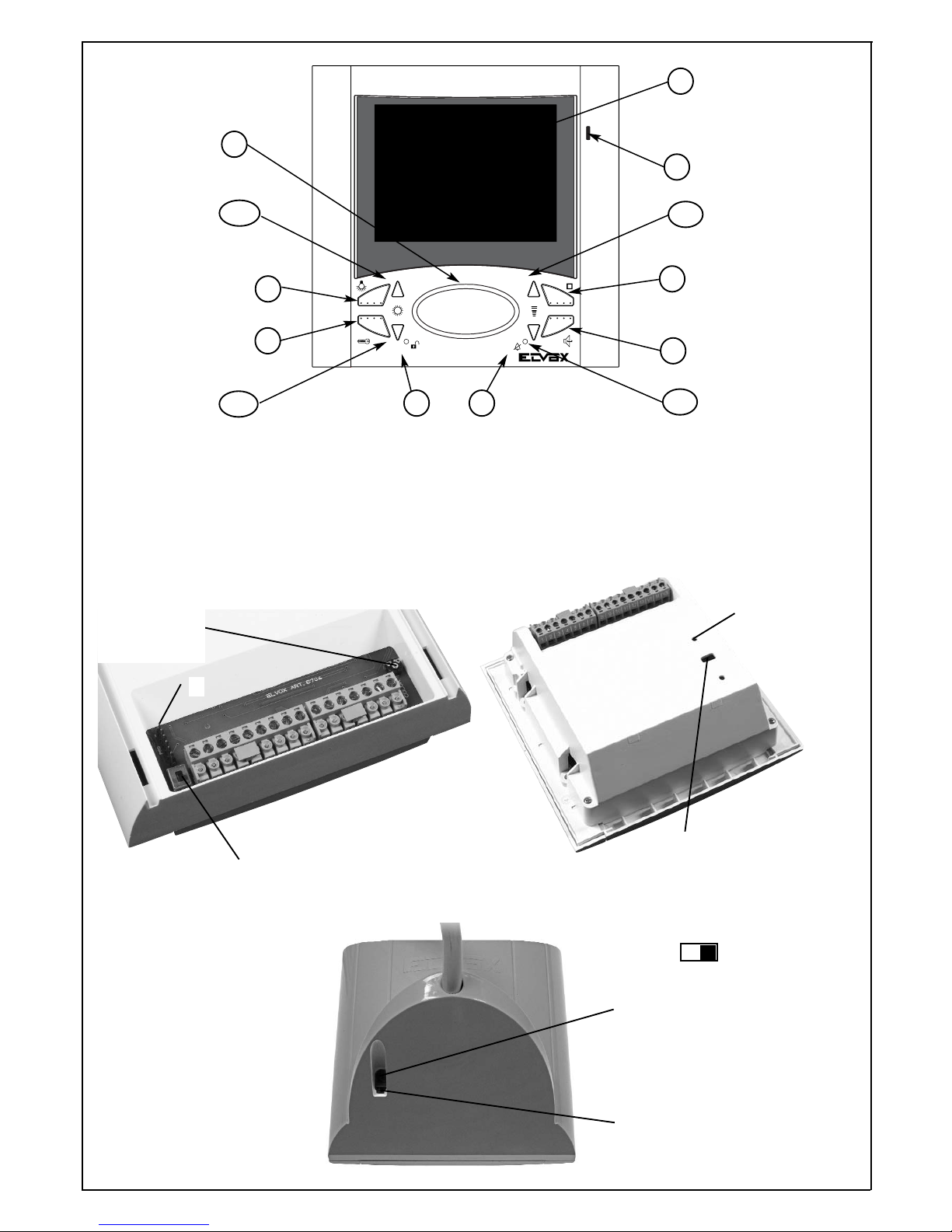
DESCRIZIONE:
Videocitofono viva voce bicanale con monitor LCD a colori 4'' o
3,5”. Lo schermo del monitor è inclinabile verticalmente.
PULSANTI E REGOLAZIONI
A) Monitor LCD 4" (6604, 660D, 6704), 3,5" (6624, 6724, 662D) a
schermo piatto.
B) Microfono
C) Altoparlante
D1-D2) Coppia
pulsanti: scelta suonerie / regolazione luminosità
E1-E2) Coppia pulsanti:
volume suonerie / regolazione contrasto /
regolazione volume fonica
F) Comando funzione F1
G) Comando chiamata verso centralino o serratura (a moni-
tor chiamato)
H) Comando funzione F2. In alternativa è possibile programmare il
tasto come funzione F3 o F4 o F5. Il pulsante programmato
come F3 o F4 o F5 funziona in modo ciclico, ad ogni pressione
del tasto cioè cambia funzione.
I) Pulsante parla/ascolta per abilitazione conversazione:
dopo la chiamata e/o l’accensione del monitor mantenere pre-
muto il pulsante per la conversazione con il posto esterno.
L) Segnalazione LED attivazione serratura esterna. La
segnalazione è opzionale in relazione al tipo di installazione.
M) Segnalazione LED per esclusione suoneria / programma-
zioni varie
MORSETTIERA DI COLLEGAMENTO
1) Linea di chiamata digitale
2) Linea fonica secondaria
3) Linea di fonica
4) Linea negativo
5) Linea +13.5 Vcc
6) Segnalazione monitor inserito (per suonerie supplementari o
altri servizi)
7) Linea negativo monitor
8) Linea positivo monitor
9) Linea per chiamata fuoriporta
10) Alimentazione distributore video al piano
11) F1 - collegamento per funzioni ausiliarie da collegare se indi-
cato nello schema
12) F2 - collegamento per funzioni ausiliarie da collegare se indi-
cato nello schema
13) Alimentazione segnalatore LED verde
V1) Ingresso segnale video
M) Massa video
V3) ingresso segnale video non coassiale
PROGRAMMAZIONE NUMERO/CODICE DI CHIAMATA
A monitor spento:
Tenere premuti contemporaneamente i tasti I e H.
Attendere 3 secondi finchè il led rosso M non inizia a lampeggiare.
A questo punto rilasciare i due tasti I e H e premere il tasto G entro
5 secondi circa per almeno 3 secondi fino all’accensione fissa del
led rosso M. Ora il dispositivo si trova nello stato programmazione
e può ricevere da una targa o dal programmatore Art. 950B il
numero da codificare. Alla ricezione del codice e dopo una corretta
programmazione, il led rosso M si spegnerà ed il dispositivo ritornerà allo stato base.
CHIAMATA FUORIPORTA
Attraverso il cablaggio del morsetto dedicato è possibile differenziare il suono di una chiamata proveniente dal pulsante fuoriporta
(ad esempio pianerottolo, entrata secondaria, ecc.) per distinguerla
da quella proveniente da un posto esterno.
Il morsetto 9 prevede l’ingresso per il filo di chiamata per una targa
fuoriporta (il posto esterno 930D) o per un semplice pulsante N.A.
(collegato tra il 9 ed il 5) che fa suonare il videocitofono con la suoneria programmata. È possibile, in seguito ad una chiamata fuoriporta, fare in modo di accendere il monitor ed inviare un comando
digitale per poter commutare il segnale video in ingresso con quello
di un’eventuale telecamera sul fuoriporta. Per fare questo bisogna:
1° abilitare l’accensione del monitor dalla chiamata fuoriporta, pre-
mere a monitor spento D1 e E1 fino al lampeggio del led rosso M e
poi premere H, 2° scegliere quale comando inviare nel bus digitale,
premere a monitor spento E1 e E2 fino al lampeggio del led rosso
M e poi premere il tasto corrispondente alla funzione , .
Page 4
4
GB
“UNANSWERED CALL” FUNCTION
By means of an external entrance panel this type of function allows the
user to signal his absence to the calling visitor; it may also be used
when the user is at home, but does not want to answer. When the function is enabled the video-interphone receiving the call does not emit an
acoustic signal, but sends a “USER ABSENT” command to a possible
switchboard and, in addition, makes the “M” red LED flash as many
times as the ananswered calls (max 4). To enable this function, it is
enough to press and hold the “D1” and “E1” push-buttons (with monitor
off) until the led M lights up, then press the “I” push-button; the Led “M”
will light up and remain ON to show the function is active.
To disable this function, with monitor off, press and hold the “D2” and
“E2” push-buttons until the led M lights up and then press the “I” pushbutton; the led switches off.
CHOOSING THE RING TONE
With monitor off, press push-button “D1” or “D2” for nearly 5 seconds to
choose the ring tone for the entrance panel call; when the first ring tone
sounds you can scroll all the ring tones by pressing several times “D1”
or “D2”.
To choose the outdoor call ring tone, (always with monitor off) press “D1”
and “D2” simultaneously for nearly 5 seconds until the red led “M” flashes intermittently; now press “D1” or “D2” to choose the ring tone.
CHIME EXCLUSION
To adjust the chime volume, with monitor off press “E1” or “E2” for at
least 5 seconds until the chime associated with the entrance panel starts
ringing. Now increase or decrease the volume by pressing the “E1” or
“E2” push-button respectively. You can get the chime exclusion by pressing continuously the “E2” push-button until the red led “M” switches on.
SELECTING THE VIDEO INPUT
The double switch on the rear of monitor (fig. 1 for 6604, 6624 und fig. 2
for 6704, 6724) selects the input video signal: for the coaxial type cable
or for the double cable.
VIDEO ADJUSTMENT
The colour adjustment is carried out by a trimmer on the rear of monitor
(fig. 1 for 6604, 6624 und fig. 2 for 6704, 6724). The brightness and contrast adjustment is made with monitor on and by two digital trimmers
pressing the “D1”, “D2” and “E1”, “E2” push-buttons respectively.
AUDIO ADJUSTMENT
To adjust the audio volume, (during a conversation) press the “E1” or
“E2” push-button together with the “I” push-button.
CHOOSING THE “H” PUSH-BUTTON OPERATION ( )
As default the pressure of push-button H routes the F command to the
digital BUS.
With the following procedure it is possible to change the operation
making the push-button lose its correspondence to “F2” and adquiring
the F3, F4, F5 functions in a cyclical way. To enable the F3, F4 and F5
functions press and hold down (with monitor off) the D1 and E1 push-
buttons at the same time until the red led M flashes, press then the F
push-button ( ); the red LED M turns off. To disable the F3, F4, F5
function (the one set as default) press the D2 and E2 push-buttons at
the same time until the red LED M flashes, now press the F push-button
( ) ; the red LED M turns off .
OPERATION
Monitors type 6604, 6624, 660D, 662D, 6704, 6724 must be used only
on digital Digibus type ELVOX video-interphone installations; for the
supply voltage use only the digibus range power supplies (for example
type 6948).
The digibus system allows you to carry out installations with digital type
device and command identification. According to the installations configuration, each device connected is identified by a 4 or 8 univocal numerical code and it is able to receive and send a data packet containing all
the information related to the communication management; in fact each
data packet includes the identification of the destination device and the
command to be carried out. All typical command operations of a videointerphone system, such as call, electrical lock release, stair-light switching on etc., are then codified.The audio and video signals are, on the
contrary, analogical type signals.
DESCRIPTION:
Monitor with “open voice" twin channel and 4'' or 3,5'' colour LCD
screen. The monitor screen may be vertically sloped.
PUSH-BUTTONS AND ADJUSTMENTS
A) Flat 4" (6604, 660D, 6704), 3,5" (6624, 6724, 662D) LCD
screen.
B) Microphone
C) Loudspeaker
D1-D2) Pair of push-buttons:chime choice / lighting adjustment
E1-E2)
Pair of push-buttons: chime volume / contrast adjustment /
volume adjustment audio line
F) Command function F1
G) Command call to the switchoboard or door lock (when
monitor is called)
H) Command function F2. In alternative it is possible to program the
push-button as function F3 or F4 or F5. The push-button
programmed as F3 or F4 or F5 operates in cyclical way, i.e.
each pressure of push-button changes function.
I) Push-button talk / listen, for conversation enabling. After
the call and/or switch-on of the monitor, hold the push-button
down for conversation with the speech unit.
L) LED Sign for external activation
M) Led indicator for chime exclusion / various programmings
TERMINAL BLOCK
1) Digital call line
2) Secondary entrance panel audio line
3) Audio line
4) Negative line
5) + 13,5V DC line
6) Inserted monitor signalling (for additional chimes or other servi-
ces)
7) Monitor negative line
8) Monitor positive line
9) Line for outside door call.
10) Supply voltage for video floor distributor
11) F1 - connection for auxiliary functions, to be connected if indica-
ted on the diagram.
12) F2 - connection for auxiliary functions, to be connected if indica-
ted on the diagram.
13) Supply voltage for green LED indicator
V1) Input for the video signal
M) Video earth
V3) Video signal input for cable other than coaxial
PROGRAMMING THE NUMBER/CALL CODE
With monitor switched off, operate as it follows:
Press simultaneously and hold the “I” and “H” push-buttons.
Wait for 3 seconds until the red led “M” starts flashing.
Release both push-buttons “I” and “H” and press the “G” push-button
within 5 seconds for at least 3 seconds until the red LED “M” is steadily lit. Now the device is on programming mode and can receive the
number to code from an entrance panel or from the programmer Art.
950B. At the code reception and after a correct programming, the red
led M switches off and the device returns to the basic mode.
OUTDOOR CALL
Through a dedicated terminal cabling it is possible to discriminate the
call tone coming from an outdoor push-button (for example passage,
secondary entry etc.) from that coming from an outdoor station.
Terminal 9 is preset for the input of the call wire for an apartment
entrance panel (the speech unit Art. 930D) or for a simple push-button N.A. (connected between 9 and 5) which make the monitor ring
through a programmed chime. On receiving an apartment outdoor
call it is possible to turn the monitor on and send a digital command
able to switch the video signal in the entrance with that of a possible
camera on the apartment door. To do so you must enable the monitor switching on (from outdoor call unit by pressing the “D1” and “E1”
push-buttons, being the monitor switched off, until the red led “M” flashes and then pressing the “H” push-button) and choose the command to route (by pressing the “E1” and “E2” push-buttons (with
monitor off) until the led M flashes and press then the push-button
corresponding to the function, , .
Page 5
5
F
DESCRIPTION :
Monitor à deux canaux à vive voix et écran de 4'' ou 3,5'' en couleurs. L'écran du moniteur peut être incliné verticalement.
BOUTONS-POSSOIRS ET RÉGLAGES
A) Moniteur LCD 4" (6604, 660D, 6704), 3,5" (6624, 6724, 662D)
à écran plat.
B) Microphone
C) Haut-parleur
D1-D2) Paire boutons-poussoirs: choix sonnerie / réglage
luminosité
E1-E2)
Paire boutons-poussoirs: volume sonnerie / réglage contraste
réglage volume phonique
F) Commande fonction F1
G) Commande appel vers le standard ou gâche (avec moni-
teur appelé)
H) Commande fonction F2. En alternative il est possible de pro-
grammer le bouton-poussoir comme fonction F3 ou F4 ou F5.
Le bouton-poussoir programmé comme F3 ou F4 ou F5
fonctionne de façon cyclique, c'est-à-dire chaque pression du
bouton-poussoir change fonction.
I)
Bouton-poussoir parle-écoute, pour validation conversation.
Après l'appel et/ou l'allumage du monteur, appuyer continuellement sur
le bouton-poussoir pour la conversation avec le poste extérieur.
L) Signalisation LED activation externe
M) Signalisation LED para exclusion sonnerie / diverses pro-
grammations.
BORNIER DE RACCORDEMENT
1) Ligne d'appel digital
2) Ligne de phonique sécondaire
3) Ligne de phonique
4) Ligne negatif
5) Ligne +13,5 V c.c.
6) Signalisation moniteur enclenché (pour sonnerie supplémentaire et d’autres services)
7) Ligne negatif moniteur
8) Ligne positif moniteur
9) Ligne pour appels porte palière
10) Alimentatin distributeur vidéo à l’étage
11) F1 - raccordement pour fonctions auxiliaires, à connecter si
indiqué dans le schéma
12) F2 - raccordement pour fonctions auxiliaires, à connecter si
indiqué dans le schéma
13) Alimentation signalisateur LED verte.
V1 Entrée signal vidéo
M) Masse vidéo
V3) Entrée signal vidéo non coaxial
PROGRAMMATION NUMÉRO/ CODE D’APPEL
Avec moniteur éteint :
Appuyer simultanément et maintenir enfoncés les boutons-poussoirs «
I » et « H ». Attendre 3 secondes jusqu’à la led rouge « M » commence
à clignoter.À ce point relâcher les deux poussoirs « I » et « H »;
appuyer sur le poussoir « G » d’ici 5 secondes pour au moins 3 secondes jusqu’à l’allumage fixe de la led rouge « M ». Maintenant le dispositif se trouve dans le mode de programmation et peut recevoir le numéro à coder depuis une plaque de rue ou depuis le programmateur Art.
950B. À la réception du code et après une correcte programmation, la
led rouge M s’éteint et le dispositif retourne au mode base.
APPEL PORTE PALIÈRE
La borne 9 est pour l’entrée du fil d’appel pour une plaque porte palière
(le poxte externe l’Art. 930D) ou pour un simple poussoir N.A. (raccordé entre le 9 et le 5) qui fait sonner le moniteur au moyen d’une sonnerie programmée. Suite à un appel de la porte palière il est possible
d’allumer le moniteur et d’envoyer une commande digitale pour pouvoir
commuter le signal vidéo en entrée avec celui d’une caméra eventuelle
à la porte palière. Pour faire cela il faut valider l’allumage du moniteur
(en appuyant appel porte palière, avec moniteur déclenché, sur “D1” et
“E1” jusqu’à ce que la led rouge « M » clignote et ensuite en appuyant
sur la touche « H ») et choisir la commande qu’on veut envoyer (en
appuyant, avec moniteur déclenché, sur « E1 » et « E2 » jusqu’à la led
M clignote et ensuite appuyer sur la touche correspondant à la fonction
,
.
FONCTION « APPEL SANS RÉPONSE »
Ce type de fonction permet à l’usager, au moyen d’une plaque de rue,
de signaliser la propre absence à celui qui appelle ; de plus, elle peut
être utilisée aussi lorsque l’usager est dans la maison, mais il ne veut
pas répondre. Quand la fonction est validée le vidéo-interphone qui
reçoit l’appel n’émet aucune signalisation acoustique, mais il envoi la
commande « USAGER ABSENT » vers un standard éventuel et, en
plus, il fait clignoter la LED rouge « M » autant de fois combien les
appels sans réponse (max. 4). Pour valider cette fonction, avec moniteur éteint, maintenir enfoncés les boutons « D1 » et « E1 » jusqu’à la
led clignote “M” et ensuite appuyer sur « I »; la Led s’allumera et restera allumée pour indiquer que la fonction est active.. Pour invalider cette
fonction, il suffit de maintenir enfoncé les poussoirs « D2 » et « E2 »
avec moniteur éteint jusqu’à la led clignote et ensuite appuyer sur «I » ;
la led s’éteint.
CHOIX DES SONNERIES
Il est possible de choisir la sonnerie à associer à l’appel depuis la plaque de rue et celle à associer à l’appel depuis la porte palière. Avec
moniteur éteint appuyer sur « D1 » ou « D2 » pour au moins 5 secondes pour choisir la sonnerie pour les appels depuis la plaque de rue,
dès que la première sonnerie sonne on peut faire défiler toutes les sonneries en appuyant plusieurs fois sur les touches “D1” et “D2”. Toujours
avec moniteur éteint, on peut choisir la sonnerie pour les appels porte
palière en appuyant sur les touches “ D1“ et “D2” simultanément pour
environ 5 secondes jusqu’à la led rouge «M» s’allume avec lumière
intermittente; maintenant appuyer sur “D1” ou “D2” pour choisir la sonnerie.
EXCLUSION DE LA SONNERIE
Pour régler le volume des sonneries, avec moniteur éteint appuyer sur
« E1 » ou « E2 » pour au moins 5 secondes jusqu’à ce que la sonnerie
associée à l’appel depuis la plaque de rue ne sonne. A ce point augmenter ou diminuer le volume en appuyant sur « E1 » ou «E2 »
respectivement. On obtient l’exclusion de la sonnerie en appuyant continuellement sur la touche « E2 » jusqu’à la led rouge « M » s’allume.
SÉLECTION ENTRÉE VIDÉO
Le double commutateur placé à l’arrière du moniteur (fig. 1 pour 6604,
6624 et fig. 2 pour 6704, 6724) sélectionne l’entrée vidéo: type pour
câble coaxial ou du type pour «boucle».
RÉGLAGE VIDÉO
Le réglage de la couleur est fait au moyen du trimmer présent à l’arrière du moniteur (fig. 1 pour 6604, 6624 et fig. 2 pour 6704, 6724). Le
réglage de la luminosité et du contraste est fait avec moniteur allumé
au moyen de deux trimmers digitaux en appuyant sur les deux touches
D1, D2 et E1, E2 respectivement.
RÉGLAGE DE L’AUDIO
Pour régler le volume de l’audio il faut appuyer (pendant une conversation) sur le bouton-poussoir «E1 » ou « E2 » simultanément avec le
poussoir «I».
CHOIX DU FONCTIONNEMENT DU BOUTON-POUSSOIR “H” ( )
Par défaut (default) la pression du bouton-poussoir H envoie la commande F2 au digital BUS. Avec la procédure suivante on peut changer
le fonctionnement en faisant perdre la correspondance avec F2 au
bouton-poussoir et en acquérant la fonction F3, F4, F5 de façon cyclique. Pour valider les fonctions F3, F4, F5 ont doit maintenir enfoncé
simultanément (avec moniteur éteint) les boutons D1 et E1 jusqu’à ce
que la LED rouge M clignote, depuis appuyer sur le bouton F ( ) ; la
LED rouge M s’éteint. Pour invalider la fonction F3, F4, F5 (celle programmée par défaut): appuyer et maintenir le doigt sur le boutons D2
et E2 jusqu’à ce que la LED rouge M clignote, ensuite appuyer sur le
bouton F ( ) ; la LED rouge M s’éteint .
FONCTIONNEMENT
Le vidéo-interphones 6604, 6624, 660D, 662D, 6704, 6724 peut être
utilisé exclusivement dans les installations de portier-vidéo ELVOX type
digital DigiBus; pour l’alimentation on doit utiliser seulement alimentations de la série DigiBus (par exemple Art. 6948). Le système DigiBus
permet de réaliser types d’installations dans lesquels l’identification des
dispositifs et des commandes est de type digital. Selon l’identification
de la configuration de l’installation, chaque dispositif raccordé est
caractérisé par un code numérique univoque à 4 ou 8 chiffres et peut
recevoir et envoyer des paquets données contenant tous les renseignements relatifs à la gestion de la communication; chaque paquet
données contient l’identification du dispositif de destination et la commande qu’il doit effectuer. Toutes les opérations typiques de commande d’un système vidéo-interphonique telles que, par exemple, appel,
ouverture de la gâche électrique, allumage lumière escalier etc., sont
donc identifiées.
La phonique pour la communication vocale et le signal vidéo pour la
visualisation des images sont, au contraire, des signaux analogiques
.
Page 6

6
D
„UNANTWORTETER RUF“- FUNKTION
Durch ein Externklingeltableau erlaubt diese Funktion dem Benutzer
ihre Abwesenheit am Rufenden anzuzeigen; dieselbe Funktion kann
auch benutzt werden als der Benutzer zu Haus ist, aber antworten
will er nicht, Soll diese Funktion freigegeben wird, so überträgt das
Video-Haustelefon (das den Ruf empfängt) keine akustische
Anzeige, aber nur einen „BENUZTER ABWESEND“-Befehl zu einer
eventuellen Zentrale, und makt die rote LED „M“ blinken wie viele
Male wie die unantworteten Rufe (max. 49). Um diese Funktion freizugeben ist es genug (mit ausgeschaltetem Monitor) die Tasten „E1“
und „E2“ zu drücken und gedrückt zu halten bis die Led blinkt und
dann die „I“ Taste drücken; die Led “M” wird sich beleuchten und
beleuchtet bleiben um zu zeigen dass die Funktion aktiv ist. Um die
Funktion auszuschalten, mit ausgeschaltetem Monitor, die „D2“ und
„E2“ Tasten drücken bis die M Led blinkt und dann die „I“ Taste
drücken; die Led erlischt.
AUSWAHL DES RUFTONS
Man kann wählen den Rufton, der am Klingeltableauruf und jener,
der am Wohntüruf zugewiesen werden kann. Um den Rufton für den
Klingeltableauruf (mit ausgeschaltetem Monitor) auszuwählen die
„D1“ oder „D2“ Taste für zirka 5 Sekunden drücken; nachdem der
erste Rufton ertönt hat, kann man durch mehrmals Drücken der „D1“
oder „D2“ Taste alle Klingeln blättern. Um den Rufton für den
Wohntürruf auszuwählen, immer mit ausgeschaltetem Monitor, die
„D1“ und „D2“ Tasten gleichzeitig drücken für zirka 5 Sekunden bis
die rote Led M sich intermittierend leuchtet; um die Klingel zu wählen
die Taste „D1“ oder „D2“ drücken.
AUSSCHALTUNG DER KLINGEL
Um die Lautstärke einzustellen, mit eingeschaltem Monitor (Abb. 1
für 6604, 6624 und Abb. 2 für 6704, 6724) die „E1“ oder „E2“ Taste
für 5 Sekunden drücken bis die mit dem Klingeltableau zugewiese
Klingel ertönt. Die Lautstärke mittels der entsprechenden Taste „E1“
oder „E2“ erhöhen oder vermindern. Die Klingelausschaltung erfolgt
durch ständiges Drücken der „E2“ Taste bis die rote Led M sich
beleuchtet.
AUSWAHL DES VIDEO-EINGANGS
Der Doppelumschalter, der sich hinter dem Monitor (Abb. 1 für 6604,
6624 und Abb. 2 für 6704, 6724) befindet, wählt den KoaxEingangsignal oder den Schleife-Eingangssignal.
EINSTELLUNG DER VIDEO
Die Farbeinstellung wird mittels eines an der Rückseite des Monitors
Trimmers durchgeführt. Die Helligkeit- und der Kontrasteinstellung
wird mit eingeschaltetem Monitor und durch zwei digitalen Trimmer
bei Drücken der entsprechenden Tasten „D1“, „D2“ und „E1“, „E2“
durchgeführt.
EINSTELLUNG DER AUDIO-LINIE
Um die „Audio“-Lautstärke einzustellen, während eines Gesprächs
die „E1“ oder „E2“. Taste gleichzeitig mit der „I“ Taste drücken.
WAHL DES TASTEBETRIEBS « H » ( )
Als Default der Druck der Taste H überträgt den Befehl F2 zum digitalen BUS. Mit folgender Prozedur kann der Betrieb verändert werden und die Übereinstimmung der Taste mit F2 abkommen lassen
und durch die Funktionen F3, F4, F5 in zyklischer Weise annehmen.
Um die Funktion F3, F4, F5 freizugeben die Tasten D1 und E1 (mit
ausgeschaltetem Monitor) gleichzeitig drücken und gedrückt halten
bis die rote LED M blinkt, dann die Taste F drücken ( ); die rote
LED
M erlischt. Um die F3, F4, F5 Funktion auszuschalten (die als
Default programmiert wurde): die D2 und E2 Tasten gleichzeitig
drücken und gedrückt halten bis die rote LED M blinkt, dann die F
Taste drücken ( ); die rote LED M erlischt.
BETRIEB
Das Video-Haustelefons Art. 6604, 6624, 660D, 662D, 6704, 6724
muss nur bei Digital-DigiBus ELVOX Anlagen verwendet werden; für
die Versorgungsspannung können nur Netzgeräte Baureihe DigiBus
(zB. Art. 6948) genutzt werden. Das DigiBus-System ermöglicht
Anlagen mit Digitalidentifizierung der Vorrichtungen und Befehle.
Gemäß der Konfiguration der Anlage, wird jede angeschlossene
Vorrichtung mittels eines 4 oder 8 eindeutigen numerischen Codes
identifiziert und kann sie Data-Packets, die alle bezüglichen
Informationen der Steuerungskommunication enthalten, empfangen
und übertragen; jedes Data-Packet umfasst die Identifizierung des
Bestimmungsorts der Vorrichtung und des entsprechenden durchfürenden Befehls. Alle bestimmten Betriebe des Befehls eines VideoHaustelefonanlage-Systems wie, zum Beispiel, Ruf, Türöffnung,
Treppenlicht-Beleuchtung usw., werden kodifiziert. Die Audio- und
Videosignale sind, dagegen, analogische Signale.
BESCHREIBUNG:
2-Canal " Frei-Handiger "mit 4'' oder 3,5'' Farbbildschirm. Der
Bildschirm des Monitors kann senkrecht geneigt werden.
TASTEN UND EINSTELLUNGEN
A) 4" (6604, 660D, 6704), 3,5" (6624, 6724, 662D) LCD-
Flachbildschirm.
B) Mikrofon
C) Lautsprecher
D1-D2) Paar Tasten: Wahl der Klingeln / Helligkeiteinstellung
E1-E2) Paar Tasten: Klingellautstärke / Kontrasteinstellung /
Lautstärkeeinstellung Audiolinie
F) Befehl Funktion F1
G)
Befehl Ruf zur Zentrale oder Türöffner (mit angerufenem Monitor)
H) Befehl Funktion F2. Als Alternative ist es möglich di Taste als
Funktion F3 oder F4 oder F5 zu programmieren. Die Taste
programmiert als F3 oder F4 oder F5 arbeitet in zyklischem
Zustand, dass heißt jeder Druck ändert Funktion.
I) „Sprechen-Hören“-Taste, für Gesprächsfreigabe. Für
Verbindung mit der Außenstation nach Ruf und/oder
Monitoreinschaltung (Taste gedrückt halten).
L) Externaktivierunganzeige LED
M) Led-Anzeige für die Klingelausschaltung / verschiedene
Programmierungen
ANSCHLUSSKLEMMENLEISTE
1) Digitale Rufleitung
2) Sekundär-Sprechleitung
3) Sprechleitung
4) Minusleitung
5) Leitung +13.5 VDC
6) Eingeschaltete Monitoranzeige (für Zuzatsklingel und andere
Dienste)
7) Monitor-Minusleitung
8) Monitor-Plusleitung
9) Leitung für Etagenruf
10) Spannungsversorgung für video Stockverteiler
11) F1 - Anschluss für Zusatzfunktionen, insofern im Schaltplan
vorgesehen
12) F2 - Anschluss für Zusatzfunktionen, insofern im Schaltplan
vorgesehen
13) Spannungsversorgung für grüne LED-Anzeige.
V1) Eingang für den Videosignal
M) Video-Erde
V3) Eingang für den Video-Signal ohne Koaxkabel.
PROGRAMMIERUNG DER NUMMER/ RUFCODE
Die Tasten beim ausgeschalteten Monitor wie folgend drücken:
Die Tasten „I“ und „H“ gleichzeitig drücken und gedrückt halten.
Warten sie auf 3 Sekunden bis die rote Led „M“ blinkt.
Die zwei Tasten „I“ und „H“ loslassen und innerhalb 5 Sekunden die
„G“ Taste für zirka 3 Sekunden drücken bis die rote Led „M“ sich
beleuchtet mit Festlicht. Jetzt befindet sich die Vorrichtung auf
Programmierungszustand und kann von einem Klingeltableau oder
dem Programmiergerät Art. 950B die kodifizierende Nummer erhalten. Nach Empfang des Codes und nach einer vollkommenen
Programmierung, erlischt die rote Led M und geht die Vorrichtung auf
die Grundzustand zurück.
WOHNTÜRRUF
Die Klemme 9 ist vorbereitet für den Rufdraht für ein WohntürKlingeltableau (außenstelle Art. 930D) oder für eine einfache Taste
(zwischen 9 und 5 angeschlossen), die einen Ton beim Monitor
durch eine programmierte Klingel erzeugt. Nach einem Ruf von der
Wohntür ist es möglich den Monitor einzuschalten und einen digitalen Befehl übertragen um das Videosignal beim Eingang mit dem
einer eventuellen Kamera an der Wohntür umschalten zu können.
Um diese Funktion zu ermöglichen ist der Monitoreinschaltung freizugeben (durch Drücken mit ausgeschaltetem Monitor) der „D1“ und
„E1“ Tasten bis die rote Led M blinkt und dann die „H“ Taste drücken
und wählen Sie den Befehl zu übertragen (bei Drücken mit ausgeschaltetem Monitor) die „E1“ und „E2“ Tasten bis die rote Led blinkt
und dann die auf der zuübertragenden Funktion entsprechende Taste
, .
Page 7

7
E
FUNCIÓN “LLAMADA SIN REPUESTA”
Este tipo di función permite al usuario, por medio de una placa
externa, de señalizar la propia ausensia a quien efectúa una llamada; además puede ser utilizada también cuando el usuario está en
la vivienda, mas no quiere responder.
Cuando la función está habilitada el videoteléfono que recibe la llamada no emite alguna señalización acústica, mas envia el mando
“USUSARIO AUSENTE” hacia una eventual central y, además, hace
parpadear el LED rojo “M” tantas veces cuantas son las llamadas sin
respuestas (4 max.). Para habilitar esta función es suficiente, siendo
el monitor apagado, pulsar y mantener presionados los pulsadores
“D1” y “E1” hasta que el led parpadee y luego pulsar “I”; el Led M se
enciende e quedrá encendio para indicar que la función es activa.
Para deshabilitar esta función, es suficiente tener presionados, con
monitor apagado, los pulsadores “D2” y “E2” hasta que el led parpadee y luego pulsar “I”; el el se apaga.
ELECCIÓN DE LOS TIMBRES
Es posible escoger el timbre que hay que asociar a la llamada desde
la placa y aquello que hay que asociar a la llamada desde la puerta
apartamiento. Con monitor apagado pulsar por al menos 5 segundos
los pulsadores “D1” o “D2” para elegir el timbre de la llamada desde
la placa; cuando el primer timbre toca se pueden desfilar todos los
otros presionando repetidamente “D1” o “D2”.
Simpre con monitor apagado, para elegir el timbre para la llamada
puerta apartamiento, pulsar por al menos 5 segundos los pulsadores
“D1” y “D2” simultáneamente hasta que el led rojo “M” se encienda
con luz intermitente; pulsar ahora “D1” o “D2” para elegir el timbre.
EXCLUSIÓN TIMBRE
Para regular el volumen de los timbres, con monitor apgado, pulsar
“E1” o “E2” por al menos 5 segundos hasta que toque el timbre
associado a la llamada desde la placa. Aumentar o disminuir el volumen pulsando “E1” o “E2” respectivamente. La exclusión del timbre
se obtiene pulsando continuamente el puslandor “E2” hasta que el
led rojo “M” se encienda.
SELECCIÓN ENTRADA VÍDEO
El doble conmutador que se encuentra detrás del monitor (fig. 1 para
6604, 6624 y fig. 2 para 6704, 6724), selecciona la señal vídeo para
el cable coaxial o para el cable trenzado.
REGULACIÓN VÍDEO
La regulación del color se hace por medio de un trimmer que se
encuentra detrás del monitor (fig. 1 para 6604, 6624 y fig. 2 para
6704, 6724). La regulación de la luminosidad y del contraste se hace
con monitor encendido y por medio de dos trimmers digitales utilizando los pulsadores “D1”, “D2” y “E1”, “E2”.
REGULACIÓN AUDIO
Para regular el volumen del audio, durante una conversación pulsar
“E1” o “E2” junto con el pulslador “I”.
ELECCIÓN DEL FUNCIONAMIENTO DEL PULSADOR ( )
Por defecto (default) la presión del pulsador “H” corresponde al
envio del mando F2 al BUS digital. Con el procedimiento siguiente
se puede cambiar el funcionamiento haciendo perder al pulsador la
correspondencia con F2 y adquiriendo la funcionalidad F3, F4, F5 de
manera cíclica. Para habilitar la función F3, F4, F5 se deben tener
presionados simultáneamente (con monitor apagado) los pulsadores
D1 y E1 hasta que el LED rojo “M” relampaguee, después presionar
el pulsador F” ( ); el LED rojo “M” se paga.
Para inhabilitar la función F3, F4, F5 (aquella programada por defecto (default)): se deben tener presionado simultáneamente los pulsadores D2 y E2 hasta que el LED rojo “M” relampaguee, luego pulsar
el pulsador F (i ); el LED rojo se apaga .
FUNCIONAMIENTO
Los vídeo-teléfonos Art. 6604, 6624, 660D, 662D, 6704, 6724 puede
ser utilizado solamente en instalaciones de videoportero ELVOX de
tipo digital DigiBus (por ejemplo Art. 6948). El sistema digiBus permite realizar tipos de instalaciones en las cuales la identificación de los
dispositivos y de los mandos es de tipo digital. Según la configuración de la instalación, cada dispositivo conectado se caracteriza por
un código numérico unívoco de 4 o 8 cifras y puede recibir y enviar
paquetes datos contenentes todas las informaciones relativas a la
gestión de la comunicación; cada paquete datos comprende la identificación del dispostivo de destinación y el mando que tiene que
efectuar. Todas la operaciones de mando típicas de un sistema
vídeotelefónico, cuales, por ejemplo, llamada, apertura de la cerradura eléctrica, encendico de la luz escalera etc., son así codificadas.
La fónica para la comunicación vocal y la señal vídeo para la visualización de las imágenes son en cambio señales de tipo analógico.
DESCRIPCIÓN:
Monitor con dos canales a viva voz y pantalla de 4'' o 3,5'' en color.
La pantalla puede ser inclinada verticalmente.
PULSADORES Y REGULACIONES
A) Pantalla plana de cristal líquido de 4" (6604, 660D, 6704), 3,5"
(6624, 6724, 662D).
B) Micrófono
C) Altavoz
D1-D2) Par pulsadores:elección timbres / regulación lumino-
sidad
E1-E2) Par pulsadores:
volumen timbres / regulación contraste /
regulación volumen fónica
F) Mando Función F1
G) Mando llamada hacia la central o cerradura (con monitor llamado)
H) Mando función F2. En alternativa es posible programar el pul-
sador como función F3 o F4 o F5. El pulsador programa-
do como F3 o F4 o F5 funciona de manera cíclica, es decir
cada presión del pulsador cambia función.
I)
Pulsador habla/escucha, para habilitación conversación.
Manter premido o botão para a conversação com o posto externo.
Permite o autoacendimento do monitor sem ter sido chamado (a
função é opcional em relação ao tipo de instalação).
L) Señalización activación externa LED
M) Señalización LED exclusión timbre / programaciones varias
REGLETA DE CONEXIONES
1) Línea de llamada digital
2) Línea fónica secundaria
3) Línea de fónica
4) Línea negativo
5) Línea + 13,5V c.c.
6) Señalización monitor insertado (para timbres suplementarios
o otros servicios).
7) Línea negativo monitor
8) Línea positivo monitor
9) Línea para llamada fuera de la puerta
10) Alimentación distribuidor vídeo a la planta
11) F1 - conexionado para funciones auxiliares; conectar si indicado en el esquema
12) F2 - conexionado para funciones auxiliares; conectar si indicado en el esquema
13) Alimentación LED indicador verde
V1) Entrada señal vídeo
M) Tierra vídeo
V3) Entrada señal vídeo para cable no coaxial.
PROGRAMACIÓN NÚMERO/ CÓDIGO DE LLAMADA
Con monitor pagado:
Pulsar simultáneamente los pulsadores “I” y “H” y mantenerlos presionados. Esperar 3 segundos hasta que el led rojo M comience a
parpadear. A este punto soltar los dos pulsadores “I” y “H”, pulsar el
pulsador “G” dentro de cerca 5 segundos por almenos 3 segundos
hasta que le led rojo “M” se encienda. Ahora el dispositivo se
encuentra en el estado de programación y puede recibitr el número
para programar desde una placa o desde el programador Art. 950B.
A la recepción del código y después de una correcta programación,
el led rojo M se apaga y el dispositivo vuelve al estado base.
LLAMADA PUERTA APARTAMIENTO
El borne “9” está predispuesto para el hilo de llamada para una
placa puerta apartamiento (aparato externo el Art. 930D) o para un
simple pulsador N.A. (conectado entre el 9 y el 5) que hace tocar
el monitor con un timbre programado. Tras una llamada desde la
puerta apartamiento es posible encender el monitor y enviar un
mando digital para poder conmutar la señal vídeo en entrada con
aquella de una cámara eventual en la puerta apartamiento. Para
hacer esto hay que habilitar el encendido del monitor (da llamada
puerta apartamiento pulsando, con monitor apagado, el pulsador
“D1” y “D2” hasta que el led rojo “M” parpadee y luego pulsando
“H”) y escoger el mando que hay que enviar (pulsando, con monitor apagado, “E1” y “E2” hasta que el led M parpadee y luego pul-
sar el pulsador correspondiente a la función , .
Page 8

8
P
DESCRIÇÃO:
Monitor de alta voz para montagen de embeber e écran de 4'' ou
3,5'' a cores. O écran pode ser inclinado verticalmente.
BOTÕES E REGULAÇÕES
A) Videotelefone LCD de 4" (6604, 660D, 6704), 3,5" (6624, 6724,
662D) com ecrâ plano.
B) Microfone
C) Altifalante
D1-D2) Par de botões: escolha campainhas /
regulação luminosidade
E1-E2) Par botões: escolha campainhas / escolha contraste /
regulação volume fónica
F) Comando função F1
G) Comando chamada para a central ou trinco (com monitor
chamado)
H) Comando função F2. Em alternativa é possível programar o
botão como função F3 ou F4 ou F5. O botão programado
como F3 ou F4 ou F5 funciona de maneira cíclica, isto é cada
pressão do botão cambia função.
I) Comando fala-escuta, para habilitação conversação,
Mantener accionado el pulsador para la conversación con el
aparato externo. Permite el autoencendido del monitor sin que
se haya producido una llamada (la función es opcional en rela-
ción con el tipo de instalación).
L) Sinalização activação externa LED
M) Sinalização LED exclusão campainha / várias programações
RÉGUA DE LIGAÇÃO
1) Linha de chamada digital
2) Linha fónica segundaria
3) Linha de fónica
4) Linha negativo
5) Linha +13.5V c.c.
6) Señalização monitor inserido (para campainhas suplementares
ou outros serviços).
7) Linha negativo monitor
8) Linha positivo monitor
9) Linha para chamadas no patamar
10) Alimentação distribuidor video no piso
11) F1 - ligação para funções auxiliares, para ligar só se requerido
pelo esquema
12) F2 - ligação para funções auxiliares, para ligar só se requerido
pelo esquema
13) Alimentação LED de sinalização verde.
V1) Entrada sinal video
M) Massa video
V3) Entrada sinal video com cabo não coaxial.
PROGRAMAÇÃO NÚMERO/ CÓDIGO DE CHAMADA
Premir oportunamente os botões seguintes:
Premir e ter premidos simultâneamente os botões “I” e “H”. Esperar
3 segundos até o led vermelho “M” comenzar a cintilar. Neste ponto
soltar os dois botões “I” e “H”, premir o botão “G” entro 5 segundos
pelo menos por 3 segundos até o led vermelho “M” se acender com
luz fixa. Agorá o dispositivo fica no estado de programação e pode
acolher um código para programar duma botoneira ou do programador. À recepção do código e após uma correcta programação, o led
vermelho M apaga-se e o dispositivo torna-se a su estado base.
CHAMADA PORTA NO PATAMAR
Através a cablagem do terminal dedicado é possível diferenciar o
som duma chamada proveniente do botão no patamar (por exemplo: patamar, entrada secundária, etc.) daquel dum posto externo. O
terminal “9” foi preparado para o fio de chamada para uma botoneira
no patamar (posto externo Art. 930D) ou para um simples botão
(ligado entre o 9 e o 5) que faz tocar o monitor com uma campainha
programada. Após uma chamada no patamer é possível fazer acender o monitor e enviar um comando digital para poder comutar o
sinal video em entrada com aquele duma telecâmara eventual no
patamar. Para fazer isto tem-se de possibiltar o acendimento do
monitor (premindo, com monitor desligado, os botões D1 e E1 até o
led vermelho “M” cintilar e após premindo “H”) e escolher o comando a enviar (premindo, com monitor desligado, “E1” e “E2” até o led
M cintilar e após premir o botão correspondiente à função , .
FUNÇÃO “CHAMADA SEM REPOSTA”
Este tipo de função permite o utente, através a botoneira externa, de
sinalizar a sua propria ausencia a quem efectua a chamada; pode
além disto ser utilizada também no caso em que o utente estã presente, mas não quer responder. Quando a função está possibilitada,
o videotelefone que receve a chamada não emete qualquer sinalização acústica, mas envia o comando “UTENTE AUSENTE” para
uma eventual central e além disso faz cintilar o LED vermelho “M”
tantas vezes quantas são as chamadas sem resposta (máx. 4). Para
disponibilizar esta função, é suficiente ter premido os botões “E1” e
“E2” , sendo o monitor desligado, até o led cintilar e após premir “I”;
o
Led se acenderá e permacerá aceso para indicar que a função é
activa
. Para deshabilitar esta função, é suficiente ter premido os
botões “D2” e “E2” (sendo o monitor desligado) até o led cintilar e
após premir “I”; o led apaga-se.
ESCOLHA DAS CAMPAINHAS
É possível escolher a campainha para associar à chamada da botoneira e aquela a associar à chamada no patamar. Sendo o monitor
desligado premir pelo menos 5 segundos o botão “D1” ou “D2” para
escolher a campainha para a chamada da botoenira; ao tocar da primeira campainha podem-se desfilar todas as outras premindo repetidamente o botão “D1” ou “D2”.
Sempre com monitor desligado, para escolher a campainha para a
chamada do patamar, premir pelo menos 5 segundos os botões
“D1” e “C2” simultâneamente até o led vermelho “M” fique intermitente, premir agorá “D1” ou “D2” para escolher a campainha.
EXCLUSÃO DA CAMPAINHA
Para regular o volume das campainhas, sendo o monitor delisgado,
premir “E1” ou “E2” pelo menos 5 segundos até a campainha associada à chamada da botoneira tocar. Agorá aumentar ou diminuir o
volume premindo “E1” ou “E2” respectivamente. A exclusão da campainha obtem-se premindo contínuamente o botão “E2” até do Led
vermelho “M” se acender.
ESCOLHA DA ENTRADA VIDEO
O duplo comutador que fica detrás do monitor (fig. 1 para 6604,
6624 e fig. 2 para 6704, 6724) seleciona o sinal video: tipo para
cabo coaxial o tipo para cabo trançado.
REGULAÇÃO DO VIDEO
A regulação da cor é feita através dum trimmer presente detrás do
monitor (fig. 1 para 6604, 6624 y fig. 2 para 6704, 6724). A regulação da luminosidade e do contraste é feita sendo o monitor aceso
e através de dois trimmers digitais premindo respectivamente os
botões “D1”, “D2” e “E1”, “E2”.
REGULAÇÃO DO AUDIO
Para regular o volume do audio, durante uma conversação premir o
botão “E1” ou “E2” simultâneamente com o botão “I” .
ESCOLHA DO FUNCIONAMENTO DO BOTÃO ( )
Por defeito (default) a pressão do botão “H” envia o comando F2 ao
BUS digital. Com o procedimento seguinte pode-se cambiar funcionamento fazendo perder ao botão a correspondência con F2 e
adquirindo a função F3, F4, F5 de maneira cíclica. Para possibilitar a
função F3, F4, F5 devem-se premir manter premidos simultâneamente (sendo o monitor desligado) os botões D1 e E1 até o LED ver-
melho “M” cintilar, depois premir o botão “F” ( ); o LED vermelho
“M” desliga-se. Para deshabilitar a função F3, F4, F5 (aquela programada por defeito (default)): devem-se premir e ter premidos simultâneamente os botões D2 e E2 até o LED vermelho “M” cintilar, depois
premir o botão “F” ( ); o LED vermelho “M” desliga-se .
FUNCIONAMENTO
Os videotelefones Art. 6604, 6624, 660D, 662D, 6704, 6724 poder
ser utilizado só nas instalações de videoporteiros ELVOX de tipo
digital DigiBus; para a alimentação devem-se utilizar exclusivamente
alimentadores da série DigiBus (por exermplo Art. 6941). Os sistema DigiBus permite realizar tipos de instalações nas quais a identificação dos dispositivos e dos comandos é de tipo digital. Conforme a
configuração da instalação, cada um dos dispositivos ligados é
caracterizado por um código unívoco numérico de 4 ou 8 cifras e
pode recever ou enviar paquetes dados contenentes todas as informações referidas à gestão da comunicação; cada paquete dados
em efeito inclui a identificação do dispositivo de destinação e o
comando a efectuar. Todas as operações de comando típicas dum
sistema de videoporteiro quais, por exemplo, chamada, apertura do
trinco eléctrico, acendimendo das luzes da escada, etc., ficam portanto codificadas.
A fónica para a comunicação vocal e o sinal video para a visualização -das imagens são, em vez, sinais de tipo analógico.
Page 9

9
INSTALLAZIONE 6604, 6624 (vedi pag. 11)
- Installare il videocitofono lontano da fonti luminose e di
calore.
- Incassare la scatola Art. 6149 (Fig. 3) al muro ad un’altezza di
circa 1,45 m dal pavimento.
- Togliere il traversino in plastica dalla scatola (vedi part. A, Fig. 3)
- Fissare il videocitofono alla scatola tramite le 4 viti in dotazione.
- Inserire le mascherine laterali, facendo attenzione che quella con
la fessura per il microfono, va inserita a destra (Fig. 3).
INSTALLATION 6604, 6624 (pag. 11)
- Install the video interphone away from sources of light and
heat.
- Flush-mount back box type 6149 (Fig. 3) in the wall at a height of
approximately 1.45 m above the ground.
- Remove the plastic cross-piece from the back box (see Part. A,
Fig. 3)
- Fix the video interphone to the back box with the 4 screws supplied
- Fit the side panels, taking care that the panel with the slot for the
microphone is fitted on the right (fig. 3).
INSTALLATION 6604, 6624 (pag. 11)
- Installer le portier-vidéo loin de toutes sources de lumière et
de chaleur.
- Encastrer le boîtier art. 6149 (Fig. 3) au mur à environ 1,45 m du
sol.
- Retirer la traverse en plastique du boîtier (voir Part. A, Fig. 3)
- Fixer le portier-vidéo au boîtier à l'aide des 4 vis fournies.
- Installer les platines latérales en faisant attention que la platine pré-
disposée avec l'ouverture micro soit placée à droite (Fig. 3).
INSTALLATION 6604, 6624 (pag. 11)
- Das Videohaustelefon fern von Licht- und Wärmequellen
installieren.
- Das UP-Gehäuse Art. 6149 (Abb. 3) auf einer Höhe von etwa 1,45
m über dem Boden an der Wand installieren.
- Die Plastikstrebe vom Gehäuse entfernen (siehe Part. A, Abb. 3)
- Das Videohaustelefon mit den 4 mitgelieferten Schrauben am
Gehäuse befestigen.
- Die seitlichen Blenden einsetzen. Die Blende mit dem Schlitz für
das Mikrofon muss rechts eingesetzt werden (Abb. 3).
INSTALACIÓN 6604, 6624 (pag. 11)
- Instalar el monitor lejos de fuentes luminosas y de calor.
- Empotrar la caja art. 6149 (Fig. 3) en la pared, a aproximadamen-
te 1,45 m del suelo.
- Quitar el travesaño de plástico de la caja (ver Part. A, Fig. 3).
- Fijar el monitor a la caja con los 4 tornillos suministrados.
- Montar las máscaras laterales teniendo en cuenta que la máscara
con la ranura para el microteléfono tiene que ir a la derecha (Fig.
3).
INSTALAÇÃO 6604, 6624 (pag. 11)
- Instalar o monitor afastado de fontes luminosas e de calor.
- Embeber a caixa Art. 6149 (Fig. 3) na parede a uma altura aprox.
de 1,45 m do pavimento.
- Retirar o travessa, em plástico, da caixa (ver Part. A, Fig. 3).
- Fixar o monitor à caixa com os 4 parafusos fornecidos.
- Inserir as máscaras laterais, tendo atenção para que a abertura
para o microfone, seja inserida à direita (Fig. 3).
INSTALLAZIONE 6604, 6624 CON LE STAFFE Art.
R660
- Praticare un foro nella parete in cartongesso di 120x120mm circa.
- Fissare le staffe al videocitofono come indicato in figura 4, tenendo i cursori allineati ai fianchi del videocitofono.
- Inserire il videocitofono all’interno della parete in cartongesso.
- Stringere le viti in modo da avvicinare i cursori alla parete di cartongesso.
- Avvitando i cursori devono allinearsi ortogonalmente al videocitofono (vedi part.1 di Fig. 4)
- Inserire le mascherine laterali, facendo attenzione che quella con
la fessura per il microfono, vada inserita a destra.
INSTALLATION OF TYPE 6604, 6624 WITH
BRACKETS TYPE R660
- Make a 120x120mm (nearly) hole in the plasterboard wall
- Fix the bracket to the monitor as indicated in figure 4, keeping the
cursors well aligned to the monitor sides.
- Insert the monitor inside the wall in plasterboard.
- Tighten the screws so as the cursors can get closer to the plasterboard wall.
- By screwing, the cursors should get aligned orthogonally to the
monitor (see Part. 1, Fig. 4)
- Insert the side grids, paying attention that the one with the slot for
the microphone must be inserted on the right.
INSTALLATION DE L’ART. 6604, 6624 AVEC LES
ÉTRIERS ART. R660
- Effectuer un trou dans la paroi en placo plâtre d’environ 120mm
x 120mm
- Fixer les étriers au moniteur comme indiqué dans la figure 4 en
tenant les curseurs bien alignés aux côtés du moniteur.
- Insérer le moniteur dans la paroi en placo plâtre.
- Visser les vis de façon à approcher les curseurs à la paroi en
placo plâtre.
- En vissant, les curseurs doivent s’aligner orthogonalement au
moniteur (voir Part. 1, Fig. 4)
- Insérer les masques latéraux en faisant attention a ce que celle
avec fente pour le microphone soit insérée à droite.
INSTALLATION DES ART. 6604, 6624 MIT HALTERUNGEN ART. R660
- Ein 120 x 120 mm (zirca) Loch in die Gipspappe-Wand durchführen.
- Die Halter durch Halten der Schieber auf der Monitorseiten vollkommen angereiht an den Monitor wie in Abb. 4 gezeigt, befestigen.
- Den Monitor in die Gipspappe-Wand einstecken.
- Die Schrauben befestigen so dass die Schieber auf die Gipspappe
nähen können.
- Durch Anschrauben dürfen die Schieber orthogonal auf dem
Monitor angereiht werden (siehe Part. 1, Abb. 4)
- Die Seitenmasken einstecken und beachten Sie dass die Maske
mit der Schlitze für das Mikrofon auf der Rechtenseite eingesteckt
werden muss.
INSTALACIÓN DEL ART. 6604, 6624 CON LOS
SUPORTES ART. R660
- Efectuar un orificio en la pared en cartón piedra de cerca
120x120mm
- Fijar los soportes al monitor como indica la figura 4, manteniendo
los cursores alineados a los lados del monitor.
- Insertar el monitor en la pared en cartón piedra.
- Fijar los tornillos de manera que los cursores se puedan acercar
a la pared de cartón piedra.
- Entornillando, los cursores deben alinearse ortogonalmente al
monitor (ver Part. 1, Fig. 4).
- Insertar las máscaras laterales prestando atención que aquella con
la apertura para el micrófono debe ser insertada a la derecha.
INSTALAÇÃO DO 6604, 6624 COM OS SUPORTES
ART. R660
- Efectuar um furo na parede, em gesso cartonado, de aprox.
120x120 mm.
- Fixar os suportes ao monitor como indica a figura 4, tendo os
cursores alinhados aos lados do monitor.
- Inserir o monitor na parede em cartão gessado.
- Parafusar os parafusos de modo a que os cursores se acerquem
à parede em cartão gessado.
- Parafusando, os cursores devem-se alinhar ortogonalmente ao
monitor (ver Part. 1, Fig. 4).
- Inserir as máscaras laterais, tendo cuidado para que a que tem
uma ranhura para o microfone, fique inserida à direita conforme
o indicado na figura.
Page 10

10
INSTALLAZIONE 6704, 6724
- Installare il videocitofono lontano da fonti luminose e di calore.
- Fissare la piastra di aggancio del videocitofono ad una altezza di
1,40m dal pavimento al bordo inferiore.
- Eseguire i collegamenti della morsettiera (vedi schemi di collegamento)
- Inserire il videocitofono seguendo il senso delle frecce 1 e 2 (Fig.
5).
- Per togliere il videocitofono dalla piastra di aggancio, agire con un
cacciavite sulla linguetta di sicurezza (posta sopra e dietro al
videocitofono) ed estrarlo seguendo il senso delle frecce 3 e 4.
INSTALLATION OF TYPE 6704, 6724
- Install the video interphone away from sources of light and
heat.
- Fix the monitor fixing plate at 1,40m. from the ground level to the
lower border.
- Connect the terminal block.
- Insert the monitor according to the 1 and 2 arrow direction (Fig.
5).
- To remove the monitor from the plate hook, operate with a screw
driver on the security lock (placed on the upper side and behind
the monitor), and remove it according to the 3 and 4 arrow direction.
INSTALLATION ART. 6704, 6724
- Installer le portier-vidéo loin de toutes sources de lumière et
de chaleur.
- Fixer la plaque d’accrochage du moniteur à une hauteur d’environ
1,40m du sol au bord inférieur.
- Effectuer les raccordements du bornier (voir schémas de raccordement)
- Insérer le moniteur en suivant le sens des flèches 1 et 2 (Fig. 5).
- Pour enlever le moniteur de la plaque d’accrochage agir avec un
tournevis sur la languette de sécurité (placée) sur la partie supérieure et derrière le moniteur) et l’extraire suivant le sens des flèches 3 et 4.
INSTALLATION DES ART. 6704, 6724
- Das Videohaustelefon fern von Licht- und Wärmequellen installieren.
- Die Befestigungsplatte des Monitors 1,40 m. in Höhe vom Boden
bis zu Unterkannt befestigen.
- Das Klemmenbrett anschliessen (siehe Shaltpläne)
- Das Videohaustelefon durch folgender Federrichtung 1 und 2 einstecken (Abb. 5).
- Um den Monitor aus der Befestigungsplatte zu entfernen, mit
einem Schraubenzieher auf die Sicherheitfeder wirken (die sich
auf der Oberseite und hinten des Videohaustelefon) und durch
Folgen der Federrichtung 3 und 4 ihn ausziehen.
INSTALACIÓN DEL ART. 6704, 6724
- Instalar el videoteléfono lejos de fuentes luminosas y de
calor.
- Fijar la placa de enganche del videoteléfono a una altura de
1,40m desde el piso al borde inferior.
- Efectuar las conexiones de la regleta de conexiones (ver esque-
mas de conexionado).
- Insertar el videoteléfono siguiendo el sentido de las flechas 1 y 2
(Fig. 5).
- Para quitar el monitor de la plancha de enganche, actuar con un
destornillador sobre la lengüeta de seguridad (que se encuentra
sobre y detrás el videoteléfono) y extraerlo siguiendo el sentido
de las flechas 3 y 4.
IINSTALAÇÃO DO 6704, 6724
Instalar o monitor afastado de fontes luminosas ed de calor.
- Fixar a placa de encaixe do monitor a uma altura de 1,40 m entre
o pavimento e obordo inferior.
- Efectuar as ligações da régua de bornes (ver esquema di
ligação)
- Inserir o videotelefone seguindo o sentido das setas 1 e 2 (Fig.
5).
- Para retirar o monitor da placa de encaixe, aplicar uma chave de
parafusos na lingueta de segurança (que fica sobre e detrás do
videotelefone) e extraí-lo seguindo o sentido das setas 3 e 4.
INSTALLAZIONE ART. 660D, 662D
- Fissare la borchia alla parete e inserire la presa nella borchia
-
Eseguire i collegamenti della morsettiera (vedi schemi di collegamento).
INSTALLATION OF TYPE 660D, 662D
- Fix the monitor support to the wall and hook the stud to the support.
- Connect the terminal block (see wiring diagrams).
INSTALLATION ART. 660D, 662D
- Fixer la bossette du moniteur à paroi et accrocher le supporte a la
bossette.
- Raccorder le bornier (voir schémas de raccordement)
INSTALLATION DES ART. 660D, 662D
- Die Buchse an die Wand befestigen un den Halter in die Buchse ein-
stecken.
- Das Klemmenbrett anchliessen (siehe Shaltplane)
INSTALACIÓN DEL ART. 660D, 662D
- Fijar la tachuela a la pared e insertar el soporte en la tachuela.
- Conectar la regleta de conexiones (ver esquemas de conexionado).
INSTALAÇÃO DO ART. 660D, 662D
- Fixar abrocha à parede e inserir o suporte na brocha.
- Efectuar as ligações da régua de bornes (ver esquema de ligação)
Page 11

11
1
2
3
4
Fig. 5
Montaggio da esterno parete
Surface wall-mounting version
Version mural en saillie
Up-Wandmontage-Version
Versión de superficie
Versão montagem saliente
40mm
141mm
139
mm
3
2
1
Microfono
Microphone
Mikrofon
Micrófono
Microfone
Fig. 4
Montaggio da incasso parete
Flush-mounted version
Montage à encastrement
Up-Montage
Versión de empotre
Versão de embeber
Microfono
Microphone
Mikrofon
Micrófono
Microfone
A
Art. 6149
Fig. 3
59mm
10mm
141mm
139
mm
136
mm
Fig. 6
Montaggio da tavolo
Table version
Montage à encastrement
Tischversion
Versión de sobremesa
Versão de mesa
141mm 125mm
125
mm
Part. 1
Page 12

12
D1- Targa per videocitofono
Video-intercom panel
Plaque de rue pour portier-vidéo
Video-Türsprechstelle
Placa para vídeo-portero
Telecâmara botoneira
Art. 8845/C
D2- Targa per videocitofono
Video-intercom panel
Plaque de rue pour portier-vidéo
Video-Türsprechstelle
Placa para vídeo-portero
Telecâmara botoneira Art. 8847/C
P- Pulsante supplementare serratura
Additional push-button for lock
Poussoir supplémentaire gâche
zusätzliche Türöffnertaste
Pulsador suplementario cerradura
Botão suplementar de trinco
L- Serratura elettrica-Electric lock
Gâche électrique-Elektrischer Türöffner
Cerradura eléctrica-Trinco eléctrico 12V ~
E1- Morsettiera di collegamento
Connection terminal block
Bornier de raccordement
Anschlussklemmenbrett
Regleta de conexión
Régua de ligação
Sezione conduttori - Conductor section
Sections des conducteurs-Leiterquerchnitt
Secciones conductores-Secção condutores
Conduttori-Conductors Ø fino a 50m-Ø up to 50m Ø fino a 100m-Ø up to 100m Ø fino a 200m-Ø up to 200m Ø fino a 500m-Ø up to 500m
Conductors-Leitungslänge Ø jusqu’à 50m-Ø bis 50m Ø jusqu’à 100m.-Ø bis 100m Ø jusqu’à 200m.-Ø bis 200m Ø jusqu’à 500m.-Ø bis 500m
Conductores-Condutores Øhasta 50m - até 50m Ø hasta 100m - até 100m Ø hasta 200m - Ø até 200m Ø hasta 500m - Ø até 500m
4, 5, 9.10 0,75 mm² 1 mm² 1,5 mm² 4mm²
- + 15, 0 ,S1 serratura, - + lock
- + 15, 0 ,S1 gâche, - + Türöffner 1 mm² 1,5 mm² 2,5 mm² -
- + 15, 0 ,S1 cerradura, - + trinco
Altri-Others-Autres
Andere-Otros-Outros 0,5 mm² 0,75 mm² 1 mm² 2,5mm²
Video Cavo coassiale 75 Ohm (tipo RG59) o RG11 a doppio isolamento
Video 75 Ohm coaxial cable (type RG59) or RG11 double insulation
Vidéo Câble coaxial 75 Ohm (type RG59) ou RG11 à double isolation
Video 75 Ohm Koaxialkabel (RG59) oder RG11 mit Doppelisolation
Vídeo Cable coaxial de 75 Ohm (tipo RG59 o RG11 com doble aislamiento)
Vídeo Cabo coaxial de 75 Ohm (tipo RG59) ou RG11 duplo isolamento.
N.B.
All’alimentatore Art. 6948 si possono collegare fino a 18 monitor Art.
6604, 6624, 660D, 662D, 6704, 6724 con la funzione “chiamata
esclusa” attiva (LED rosso acceso).
Per collegare dei monitor aggiuntivi utilizzare l’alimentatore supplementare Art. 6942.
Note:
Up to 18 monitors type 6604, 6624, 660D, 662D, 6704, 6724 with
the "call excluded" function activated (red LED switchbed on) can be
connected to power supply type 6948. To connect additional monitors use additional power supply type 6942.
N.B.
À l'alimentation Art. 6948 on peut connecter jusqu'à 18 moniteurs
Art. 6604, 6624, 660D, 662D, 6704, 6724 avec la fonction "appel
exclu" active (LED rouge allumée).
Pour raccorder des moniteurs supplémentaires utiliser l'alimentation
supplémentaire Art. 6942.
HINWEIS:
Am Netzgerät Art. 6948 können bis zu 18 Monitoren Art. 6604, 6624,
660D, 662D, 6704, 6724 mit der "Ruf ausgenommen"-Funktion activ
(rote LED angeschaltet) angeschlossen werden. Um
Zusatzmonitoren anzuschliessen, Zusatznetgerät Art. 6942 verwenden.
N.B.
Al alimentador Art. 6948 se pueden conectar hasta 18 monitores Art.
6604, 6624, 660D, 662D, 6704, 6724 con la función de "llamada
excluída" activa (LED rojo encendido). Para conectar monitores adicionales utilizar el alimentador suplementar Art. 6942.
N.B.
Ao alimentador Art. 6948 podem-se ligar até 18 monitores Art. 6604,
6624, 660D, 662D, 6704, 6724 com a função de "chamada excluida"
activa (LED vermelho aceso). Para ligar alguns monitores suplementares utilizar o alimentador suplementar Art. 6942.
E2- Unità elettronica
Electronic unit
Unité électronique
Elektronische Einheit
Unidad electrónica
Unidade electrónica
E3- Moduli supplementari serie 8A...
Additional modules range 8A.
Modules supplémentaires série 8A..
Zusatzmodule baureihe 8A...
Módulos suplementarios serie 8A...
Módulo suplementares da série 8A...
Page 13

75ohm75ohm
75ohm 75ohm
-+345V1
V3
13
V1
11
12
M
-
+
8
9
6
7
3
4
1
2
5
10
453V1
V4
V3
V2
V1
V
-
V
+
M2 V2 V1 M1 S1
-
+I
PRI
4
R2
4
O15+543F2F1SCH
R1
10
5
2
1
4
3
7
6
9
8
M
12
11
13
V1
V3
V3
V1
13
11
12
M
8
9
6
7
3
4
1
2
5
10 10
5
2
1
4
3
7
6
9
8
M
12
11
V1
13
V3
L
P
+I
SR
CH
5
3
4
1
V
+L
M1
V2
+I
SR
V1
VL
F1
4
F2
CH
V
3
1
M
5
8
6
4
+L
M1
V2
+I
SR
V1
VL
F1
4
F2
CH
V
3
1
M
5
8
6
4
J1
D
J1
DO
DDO
+I
CH
SR
5
3
4
1
V
6
3
C
9
5
2
1
4
0
R
7
8
88888888
*
MONTANTE MONITOR
MONITOR CABLE RISER
MONTANT MONITEUR
MONITORSTEIGLEITUNG
COLUNA MONTANTE DE
MONITORES
Art. 6948
N° SI205
In ogni monitor inserire tra i morsetti V-M la
resistenza di 75 Ohm
fornita in dotazione.
Connect 75 Ohm resistor (supplied) in each
monitor, between terminals V-M.
Raccorder dans tous
les moniteurs la résistance de 75 Ohms
fournie entre les bornes V-M.
Bei allen Monitoren
zwischen Klemmen VM den mitgelieferten
75 Ohm
Abschlusswiderstand
montieren.
Montar la resistencia
de 75 Ohm suministrada de serie entre
los bornes V-M en
cada monitor.
Em cada monitor
inserir a resistência
de 75 Ohm fornecida
entre os bornes V-M.
*
*
MONITOR COLORI
COLOUR MONITOR
MONITEUR COULEURS
FARBMONITOR
MONITOR A COLORES
MONITOR CORES
Art. 6604, 6624
Art. 6704, 6724
Art. 660D, 662D
IMPIANTO CONDOMINIALE VIDEOCITOFONICO DIGITALE CON MONITOR E CITOFONI CON DECODIFICA INTERNA.
DIGITAL DOOR ENTRY AND VIDEO SYSTEMS FOR CONDOMINIUM WITH MONITORS AND INTERPHONES WITH AN INTERNAL DECO-
DING FACILITY.
INSTALLATION DE PORTIER-VIDÉO DIGITAL DE COPROPRIETÉ AVEC MONITEURS ET POSTES D’APPARTEMENTS AVEC DECODAGE INTERNE.
DIGITALVIDEOTÜRSPRECHANLAGE FÜR MEHRFAMILIENHÄUSERN MIT MONITOREN UND HAUSTELEFONEN MIT
DEKODIERUNG.
INSTALACIÓN CONDOMINIAL DE VÍDEO PORTERO CON MONITORES E INTERFONOS CON DECODIFICACIÓN NTERNA.
INSTALAÇÃO DE CONDOMÍNIO PARA PORTEIRO DIGITAL VIDEO COM MONITORES E INTERFONES EQUIPADOS COM INTERNO.
ALIMENTATORE
POWER SUPPLY
ALIMENTATION
NETZGERÄT
ALIMENTADOR
RETE-NETWORK
RÉSEAU-NETZ
RED-REDE
13
MONITOR COLORI
COLOUR MONITOR
MONITEUR COULEURS
FARBMONITOR
MONITOR A COLORES
MONITOR CORES
Art. 6604, 6624
Art. 6704, 6724
Art. 660D, 662D
MONITOR COLORI
COLOUR MONITOR
MONITEUR COULEURS
FARBMONITOR
MONITOR A COLORES
MONITOR CORES
Art. 6604, 6624
Art. 6704, 6724
Art. 660D, 662D
MONITOR COLORI
COLOUR MONITOR
MONITEUR COULEURS
FARBMONITOR
MONITOR A COLORES
MONITOR CORES
Art. 6604, 6624
Art. 6704, 6724
Art. 660D, 662D
DISTRIBUTORE
DISTRIBUTOR
DISTRIBUTEUR
VERTEILER
DISTRIBUIDOR
Art. 5556/004
Art. 5555
Page 14

14
VARIANTE-VERSION-SONDERSCHALTUNG-VARIACIÓN 1
75ohm75ohm
V3
V1
13
11
12
M
8
9
6
7
3
4
1
2
5
10
120
PRI
10
5
2
1
4
3
7
6
9
8
M
12
11
13
V1
V3
1V543+-
-+345V1
PF
F
3
F1
5
6
4
2
1
L
P
K
K
F2
R
K- Pulsante fuori porta
Outdoor push-button
Poussoir à la porte de l’appartement
Wohnungstür-Klingelknopf
Pulsador puerta apartamiento
Botão de patamar
Monitor
Moniteur
Art. 6604, 6624
Art. 6704, 6724
Art. 660D, 662D
Trasformatore
Transformer
Transformateur
Transformator
Transformador
Art. M832
Rete
Mains
Réseau
Netz
Red
Rede
N° SI206
Monitor
Moniteur
Art. 6604, 6624
Art. 6704, 6724
Art. 660D, 662D
MONTANTE MONITOR
MONITOR CABLE RISER
MONTANT MONITEUR
MONITORSTEGLEITUNG
MONTANTE MONITOR
COLUNA MONTANTE PARA OS MONITORES
L- Serratura elettrica-Electric lock
Gâche électrique-Elektrischer Türöffner
Cerradura eléctrica-Trinco eléctrico 12V ~
P- Pulsante supplementare serratura
Additional push-button for lock
Poussoir supplémentaire gâche
zusätzliche Türöffnertaste
Pulsador suplementario cerradura
Botão suplementar de trinco
F2- Lampada luce targa
Bulb for panel lighting
Lampe d’éclairage plaque
Birne für Tastenbeleuchtung
Lámpara luz escalera
Lâmpada da luz da botoneira
(3x24V 3W max.)
10x24V 3W con/with Art. M832
16X24V 3W con/with Art. 832/030
Variante di collegamento per monitor Art. 6604, 6624 con
pulsante chiamata fuoriporta.
Variation of wiring diagram for monitor type 6604, 6624
with push-button for outdoor call.
Variation de raccordement pour moniteur Art. 6604, 6624
avec bouton-poussoir pour appel porte palière.
Sonderschaltung für Monitor Art. 6604, 6624 mit Taste für
Wohntürruf.
Variación de conexionado para monitor Art. 6604, 6624
con pulsador para llamada puerta apartamiento.
Variante de ligação para monitor Art. 6604, 6624 com
botão para chamada no patamar.
F- Targa audio secondaria
Secondary audio entrance panel
Plaque de rue audio sécondaire
Audio-Nebenklingeltableau
Placa audio secundaria
Botoneira audio secundária
F1- Gruppo fonico Art. 930D
Speech unit type 930D
Poste externe audio Art. 930D
Audio-Außenstelle Art. 930D
Aparato externo audio Art. 930D
Posto externo audio Art. 930D
PF- Pulsante per apertura serratura fuori porta
Push-button for the outdoor lock opening.
Bouton-poussoir pour ouverture de la gâche
porte palière.
Taste für die Öffnung des Wohntürschlosses.
Pulsador para la abertura de la cerradura
puerta apartamiento.
Botão para a abertura do trinco no patamar.
Variante di collegamento per monitor Art. 6604, 6624 o con targa citofonica fuoriporta
con posto esterno Art. 930D
Variation of wiring diagram for monitor type 6604, 6624 or with outdoor audio entrance
panel with speech unit type 930D.
Variation de raccordement pour moniteur Art. 6604, 6624 ou avec plaque audio porte
palière avec poste externe Art. 930D.
Sonderschaltung für Monitor Art. 6604, 6624 oder mit Audio-Wohnklingeltableau mit
Außenstelle Art. 930D.
Variación de conexionado para monitor Art. 6604, 6624 o con placa audio puerta apartamiento con aparato externo Art. 930D.
Variante de ligação para monitor Art. 6604, 6624 ou com botoneira audio no patamar
com posto externo Art. 930D.
MONTANTE MONITOR
MONITOR CABLE RISER
MONTANT MONITEUR
MONITORSTEGLEITUNG
MONTANTE MONITOR
COLUNA MONTANTE PARA OS MONITORES
K- Pulsante fuori porta
Outdoor push-button
Poussoir à la porte de l’appartement
Wohnungstür-Klingelknopf
Pulsador puerta apartamiento
Botão de patamar
Page 15

15
VARIANTE-VERSION-SONDERSCHALTUNG-VARIACIÓN 2
75ohm
+U
+U
PRI
D+U-BAC+I
-+345V1
R1
CHSF1F2345+ 150
4
R2
4
PRI
+I
-
S1M1V1V2M2
1V354
+
-
V3
V1
13
11
12
M
8
9
6
7
3
4
1
2
5
10
P
L
+L
M1
V2
+I
SR
V1
VL
F1
4
F2
CH
V
3
1
M
5
8
6
4
+L
M1
V2
+I
SR
V1
VL
F1
4
F2
CH
V
3
1
M
5
8
6
4
J1
D
J1
DO
DDO
CH
SR
V
1
4
3
5
+I+I
CH
SR
5
3
4
1
V
6
3
C
9
5
2
1
4
0
R
7
8
88888888
*
F1
F2
Collegamento variante porta aperta
con led verde.
Variation of wiring diagram for “open
door” mit green led.
Raccordement variante "porte ouverte" avec led verte.
Anschluss für die "Geöffnete tür"-sonderschaltung mit grüner led.
Conexionado variación "puerta abierta" con led verde.
Ligação variante "porta aberta" com
led verde.
MONTANTE MONITOR - MONITOR CABLE RISER
MONTANT MONITEUR - MONITORSTEGLEITUNG
MONTANTE MONITOR - COLUNAMONTANTE PARA OS MONITORES
Alimentatore-Power supply
Alimentation-Netzgerät
Alimentador Art. 6948
Rete
Mains
Réseau
Netz
Red
Rede
Monitor
Moniteur
Art. 6604, 6624
Art. 6704, 6724
Art. 660D, 662D
Alimentatore-Power supply
Alimentation-Netzgerät
Alimentador Art. 6582
Rete
Mains
Réseau
Netz
Red
Rede
N° SI210
Lo schema illustra il collegamento della segnalazione
di serratura aperta (LED verde) con monitor Art.
6604, 6624, 660D, 662D, 6704, 6724 (collegamento
al morsetto 11).
Se si collegano fino a 5 monitor, non è necessario
utilizzare l’alimentatore Art. 6582, ma è sufficiente utilizzare il morsetto “+” del 6948 per alimentare il led
verde. Per escludere la segnalazione di serratura
aperta non collegare il morsetto N. 11 dei monitor.
La segnalazione di suoneria esclusa è già inserita nei
monitor e non serve collegare nessun conduttore
supplementare.
I LED rossi sono alimentati dall’alimentatore 6948
che può alimentare massimo 18 e non devono essere in totale più di 20. Oltre tale numero ricorrere ad
un alimentatore supplementare.
The diagram shows the connection of the "lock
open" indicator (green LED) with monitor Art.
6604, 6624, 660D, 662D, 6704, 6724 (connection to terminal 11). Should up to 5 monitors be
connected, it is not necessary the use of power
supply Art. 6582, but it is sufficient to use terminal “+” of power supply type 6948 to power the
green led. To disable the "lock open" indication,
do not connect terminal No 11 of the monitors.
The ringtone OFF indication is already inserted
in the monitors and it is not necessary to connect any additional conductor.
The red LEDs are powered by the power supply 6948 and must not exceed a total of 18 in
number. For larger numbers, use an additional
power supply.
Le schéma représente le raccordement de la signalisation de
gâche ouverte (LED verte) avec moniteur Art. 6604, 6624,
660D, 662D, 6704, 6724 (raccordement à la borne 11).
Si on raccorde jusqu’à 5 moniteurs, il n’est pas nécessaire d’utiliser l’alimentation Art. 6582, mais il est suffisant
d’utiliser la borne « + » de l’alimentation Art. 6948 pour
alimenter la led verte.
Pour exclure la signalisation de gâche ouverte, ne pas connecter le borne N. 11 des moniteurs.
La signalisation de sonnerie exclue est déjà prévue dans les
moniteurs si bien qu'acun conducteur supplémentaire ne doit
être raccordé.
Les LED rouges sont alimentées par l'alimentation 6948, leur
nombre max étant de 18 et il ne peut y en avoir au total plus
de 20. Au-delà de ce nombre, il faudra installer des alimentations supplémentaires.
Page 16

16
75ohm
1C
+
-
RC
342515
10
5
2
1
4
3
7
6
9
8
M
12
11
13
V1
V3
VARIANTE-VERSION-SONDERSCHALTUNGVARIACIÓN 3
Collegamento suonerie supplementari a timpano con monitor
muniti di decodifica interna.
Si possono collegare suonerie supplementari funzionanti a 12V c.a.
utilizzando il relè Art. 170/101 collegandolo come da schema.
Portata dei contatti 3A-250V.
Supplementary membrane bell connection for monitors
without internal decoding.
12V A.C. additional bells can be fitted using the relay Art. 170/101
connected as shown in the diagram.
Contact rating 3A - 250V
Raccordement sonneries supplémentaires à timbre avec moniteurs équipés du décodage interne.
On peut raccorder des sonneries supplémentaires en 12V c.a. avec
le relais Art. 170/101 raccordé suivant le schéma.
Portée des contacts 3A-250V.
Anschluß zusätzlicher Läutwerke an Monitoren mit interne
Decodierung.
Es ist möglich, zusätzliche 12V AC Lautwerke zu installieren, in
dem das Relais Art. 170/101 gemäß Schema angeschlossen wird.
Stromfestigkeit der Kontakte 3A-250V
Conexionado timbres suplementarios con monitores provistos
de codificación interna.
Se pueden conectar timbres suplementarios funcionantes con 12V
c.c. utilizando el relé Art. 170/101 conectándolos como desde
esquema. Capacidad de los contactos 3A-250V.
Ligação das campaínhas suplementares com monitores com
descodificador interno.
Podem-se ligar campaínhas suplementares funcionando a 12V c.a.
utilizando o relé Art. 170/101, ligando-o como mostra o esquema.
Carga nos contactos 3 A-250 V.
N.B.
Se vengono collegate suonerie supplementari con elevato assorbimento
effettuare anche il collegamento tra i morsetti RC-4 del relè Art. 170/101.
If additional bells with high absorption are fitted, also connect terminals
RC-4 of relay Art. 170/101.
Si on raccorde des sonneries supplémentaires ayant une absorption
élevée, effectuer également le raccordement entre les bornes RC-4 du
relais Art. 170/101.
Bei Anschluß zusätzlicher Läutwerke mit hoher Stromaufnahme auch die
Klemmen RC-4 des Relais Art. 170/101 verbinden.
Si se conectan timbres suplementarios con elevada absorción efectuar
también el conexionado entre los bornes RC-4 del relé Art. 170/101.
Se forem utilizadas campaínhas suplementares com elevado consumo
efectuar, também, a ligação entre os bornes RC-4 do relé Art. 170/001.
Alimentazione suoneria
Bell supply
Alimentation sonnerie
Versorgung des Läutwerks
Alimentación timbre
Alimentação da campainha
Suoneria
Bell
Sonnerie
Läutwerk
Timbre
Campainha
12V c.a./~
Relè - Relay - Relais
Art. 170/101
Monitor
Moniteur
Art. 6604, 6624
Art. 6704, 6724
Art. 660D, 662D
N° SI208
Auf dem Plan ist der Anschluss der Anzeige „Tür
offen”
(grüne LED) an Monitor Art. 6604, 6624, 660D, 662D,
6704, 6724 (Anschluss an Klemme 11) dargestellt.
Soll bis zu 5 Monitoren verwendet werden, so ist es
nicht notwendig das Netzgerät Art. 6582 zu verwenden, ist es aber genug die Klemme „+“ des Netzgeräts
Art. 6948 zu verwenden um die grüne Led zu versorgen. Um die Anzeige „Tür offen” auszuschließen, die
Monitorklemme Nr. 11 nicht anschließen.
Die Anzeige für Ruftonabschaltung ist bereits in den
Monitor integriert, es muss kein weiterer Leiter angeschlossen werden.
Die roten LEDs (max. 18) werden vom Netzgerät
6948. Darüber hinaus ist ein zusätzliches Netzgerät
erforderlich.
El esquema ilustra la conexión de la señalización
de cerradura abierta (LED verde) con monitor Art.
6604, 6624, 660D, 662D, 6704, 6724 (conexión al
borne 11).
Si se conectan hasta 5 monitores, no es necesario
utilizar el alimentador Art. 6582, mas es suficiente
utilizar el borne “+” del alimentador Art. 6948 para
alimentar el led verde.
Para excluir la señalización de cerradura abierta,
no hay que conectar el borne N. 11 de los monitores.
La señalización de timbre excluido ya se ha conectado en los monitores y no es necesario conectar
ningún conductor suplementario.
Los leds rojos se alimentan mediante el alimentador 6680, y, cómo máximo, puede haber 18. Si se
supera dicho número, se debe emplear un alimentador suplementario.
O esquema refere-se à ligação da sinalização de
trinco aberto (LED verde) com monitores Art.
6604, 6624, 660D, 662D, 6704, 6724 (ligação ao
borne 11). Se se ligarem até 5 monitores, não é
necessário utilizar o alimentador Art. 6582, mas
è suficiente utilizar o terminal “+” do alimentador
Art. 6948 para alimentar o led verde. Sem sinalização de trinco aberto não é ligado o borne N.
11 dos monitores
A sinalização de campainha excluída é uma
função inserida nos monitores, pelo que não
serve ligar condutores suplementares aos
esquemas base.
Os LEDs vermelhos são alimentados pelo alimentador 6680 e não devem ser no total mais de
18. Para valores superiores deve-se recorrer a
um alimentador suplementar.
Page 17

17
75ohm
10
5
2
1
4
3
7
6
9
8
M
12
11
13
V1
V3
-
+
453V1
M2 V2 V1 M1 S1
-
+I
PRI
4
R2
4
O15+543F2F1SCH
R1
12345 54321
CNO NOC
1V543+-
L
P
+L
M1
V2
+I
SR
V1
VL
F1
4
F2
CH
V
3
1
M
5
8
6
4
+L
M1
V2
+I
SR
V1
VL
F1
4
F2
CH
V
3
1
M
5
8
6
4
J1
D
J1
DO
DDO
CH
SR
V
1
4
3
5
+I+I
CH
SR
5
3
4
1
V
6
3
C
9
5
2
1
4
0
R
7
8
88888888
*
F1
F2
VARIANTE-VERSION-SONDERSCHALTUNG-VARIACIÓN 4
Relè - Relay - Relais
Art. 170/001
Funzione supplementare “F1” e “F2”
“F1”, “F2” additional function
Fonction supplémentaire “F1” et “F2”
“F1” und “F2” zusätzliche Funktion
Función suplementaria “F1”, “F2”
Função suplementar “F1”, “F2”
Alimentatore
Power supply
Alimentation
Netzgerät
Alimentador
Art. 6948
MONTANTE MONITOR
MONITOR CABLE RISER
MONTANT MONITEUR
MONITORSTEGLEITUNG
MONTANTE MONITOR
COLUNA MONTANTE PARA OS MONITORES
Rete-Mains
Réseau-Netz
Red-Rede
Monitor
Moniteur
Art. 6604, 6624
Art. 6704, 6724
Art. 660D, 662D
N° SI207
Relè - Relay - Relais
Art. 170/001
Page 18

18
Anschluß der Zusatzfunktion F1-F2 an Video-Türsprechanlagen mit interner Decodierung.
Es ist möglich, eine über den Monitor gesteurte Zusatzfunktion (F1) zu aktivieren, indem ein Relais Art. 170/001 gemäß Schema angeschlossen wird (Klemmen R1-4 des Netzgeräts). Für die Zuzatsfunktion F2 ein Relais Art. 170/001 einsetzen und es an Klemmen R2-4 des
Netzgerats anschließen. Monitorstaste " " aktiviert die F1 Funktion. Monitorstaste " " aktiviert die F2 Funktion
Conexionado función auxiliares F1-F2 en instalaciones con vídeo portero provistos de codificación interna.
Es posible la activación de una función auxiliar (F1) mandada por los monitores conectando un relé Art. 170/001 como de esquema (bornes
R1-4 del alimentador). Para la function ausiliar F2 insertar un relé Art. 170/001 y conectarlo a los bornes R2-4 del alimentador. El pulsador "
" del monitor activa la función F1. El pulsador " " del monitor activa la función F2
Ligação das funções auxiliares F1 - F2 em instalações de video-porteiro equipadas com descodificador interno.
É possível a activação de uma função auxiliar (F1) comandada do monitor ligando um relé Art. 170/001 como mostra o esquema (bornes R1-4
do alimentador). Para a função auxiliar F2 inserir um relé Art. 170/001 e o ligar aos terminais R2-4 do alimentador. O botão " " do monitor
ativa a função F1. O botão " " do monitor ativa a função F2
Collegamento funzione ausiliaria F1-F2 in impianti videocitofonici muniti di decodifica interna.
È possibile l’attivazione di una funzione ausiliaria F1 comandata dai monitor collegando un relè Art. 170/001 come da schema (morsetti R1-4
dell’alimentatore). Per la funzione ausiliaria F2 inserire un relè Art. 170/001 e collegarlo ai morsetti R2-4 dell’alimentatore. Il tasto " " del
monitor attiva la funzione F1. Il tasto " " del monitor attiva la funzione "F2".
Connecting additional function F1-F2 to video door entry systems with internal decoding.
An additional monitor controlled function F1 can be activated by connecting relay Art. 170/001 as per diagram (terminals R1-4 of the power sup-
ply). For the F2 auxiliary function insert a relay type 170/001 and connect it to the power supply terminals R2-4. Monitor push-button " " acti-
vates the F1 function. Monitor push-button " " activates the F2 function.
Connexion de la fonction auxiliaire F1-F2 dans des installations portiers vidéo équipés du décodage interne. On peut activer une fonction auxiliaire (F1) commandée par les moniteurs en reliant un relais Art. 170/001 selon le schéma (bornes R1-4 de l’alimentation). Pour la fonction auxiliaire F2 insérer un relais Art. 170/001 et le connecter aux bornes R2-4 de l'alimentation.
Le bouton-poussoir " " du moniteur active la fonction F1. Le bouton-poussoir " " du moniteur active la fonction F2.
Page 19

19
AVVERTENZE PER L'INSTALLATORE
- Leggere attentamente le avvertenze contenute
nel presente documento in quanto forniscono
importanti indicazioni riguardanti la sicurezza di
installazione, d'uso e di manutenzione.
- Dopo aver tolto l'imballaggio assicurarsi dell'integrità dell'apparecchio. Gli elementi dell'imballaggio (sacchetti di plastica, polistirolo espanso,
ecc.) non devono essere lasciati alla portata dei
bambini in quanto potenziali fonti di pericolo.
L'esecuzione dell'impianto deve essere rispondente alle norme CEI vigenti.
- È necessario prevedere a monte dell'alimentazione un appropriato interruttore di tipo bipolare
con separazione tra i contatti di almeno 3mm.
-
Prima di collegare l'apparecchio accertarsi che i
dati di targa siano rispondenti a quelli della rete di
distribuzione.
- Questo apparecchio dovrà essere destinato solo
all'uso per il quale è stato espressamente concepito, e cioè per sistemi di citofonia. Ogni altro
uso è da considerarsi improprio e quindi pericoloso. Il costruttore non può essere considerato
responsabile per eventuali danni derivanti da usi
impropri, erronei ed irragionevoli.
-
Prima di effettuare qualsiasi operazione di pulizia o
di manutenzione, disinserire l'apparecchio dalla rete
di alimentazione elettrica, spegnendo l'interruttore
dell'impianto.
- In caso di guasto e/o di cattivo funzionamento
dell'apparecchio, togliere l'alimentazione mediante l'interruttore e non manometterlo. Per l'eventuale riparazione rivolgersi solamente ad un centro di assistenza tecnica autorizzato dal costruttore. Il mancato rispetto di quanto sopra può compromettere la sicurezza dell'apparecchio.
- Non ostruire le aperture o fessure di ventilazione
o di smaltimento calore e non esporre l’apparecchio a stillicidio o spruzzi d’acqua.
- L'installatore deve assicurarsi che le informazioni
per l'utente siano presenti sugli apparecchi
derivati.
-
Tutti gli apparecchi costituenti l'impianto devono
essere destinati esclusivamente all'uso per cui sono
stati concepiti.
- Questo documento dovrà sempre rimanere allegato alla documentazione dell'impianto.
Direttiva 2002/96/CE (WEEE, RAEE).
Il simbolo del cestino barrato riportato sull’apparecchio indica che il prodotto, alla fine della propria vita
utile, dovendo essere trattato separatamente dai
rifiuti domestici, deve essere conferito in un centro di
raccolta differenziata per apparecchiature elettriche
ed elettroniche oppure riconsegnato al rivenditore al
momento dell’acquisto di una nuova apparecchiatura equivalente.
L’utente è responsabile del conferimento dell’apparecchio a fine vita alle appropriate strutture di raccolta. L’adeguata raccolta differenziata per l’avvio successivo dell’apparecchio dismesso al riciclaggio, al
trattamento e allo smaltimento ambientalmente compatibile contribuisce ad evitare possibili effetti negativi sull’ambiente e sulla salute e favorisce il riciclo dei
materiali di cui è composto il prodotto. Per informazioni più dettagliate inerenti i sistemi di raccolta
disponibili, rivolgersi al servizio locale di smaltimento
rifiuti, o al negozio in cui è stato effettuato l’acquisto.
Rischi legati alle sostanze considerate pericolose (WEEE).
Secondo la nuova Direttiva WEEE sostanze che da
tempo sono utilizzate comunemente su apparecchi
elettrici ed elettronici sono considerate sostanze
pericolose per le persone e l’ambiente. L’adeguata
raccolta differenziata per l’avvio successivo dell’apparecchio dismesso al riciclaggio, al trattamento e
allo smaltimento ambientalmente compatibile contribuisce ad evitare possibili effetti negativi sull’ambiente e sulla salute e favorisce il riciclo dei materiali
di cui è composto il prodotto.
SAFETY INSTRUCTIONS FOR INSTALLERS
- Carefully read the instructions on this leaflet: they
give important information on the safety, use and
maintenance of the installation.
- After removing the packing, check the integrity of
the set. Packing components (plastic bags,
expanded polystyrene etc.) are dangerous for
children. Installation must be carried out according to national safety regulations.
- It is convenient to fit close to the supply voltage
source a proper bipolar type switch with 3 mm
separation (minimum) between contacts.
- Before connecting the set, ensure that the data
on the label correspond to those of the mains.
- Use this set only for the purposes designed,
i.e.for electric door-opener systems. Any other
use may be dangerous. The manufacturer is not
responsible for damage caused by improper,
erroneous or irrational use.
- Before cleaning or maintenance, disconnect the
set.
- In case of failure or faulty operation, disconnect
the set and do not open it.
- For repairs apply only to the technical assistance
centre authorized by the manufacturer.
- Safety may be compromised if these instructions
are disregarded.
- Do not obstruct opening of ventilation or heat exit
slots and do not expose the set to dripping or
sprinkling of water.
- Installers must ensure that manuals with the
above instructions are left on connected units
after installation, for users' information.
- All items must only be used for the purposes
designed.
- This leaflet must always be enclosed with the
equipment.
Directive 2002/96/EC (WEEE)
The crossed-out wheelie bin symbol marked on the
product indicates that at the end of its useful life, the
product must be handled separately from household
refuse and must therefore be assigned to a differentiated collection centre for electrical and electronic
equipment or returned to the dealer upon purchase
of a new, equivalent item of equipment.
The user is responsible for assigning the equipment,
at the end of its life, to the appropriate collection
facilities.
Suitable differentiated collection, for the purpose of
subsequent recycling of decommissioned equipment
and environmentally compatible treatment and
disposal, helps prevent potential negative effects on
health and the environment and promotes the recycling of the materials of which the product is made.
For further details regarding the collection systems
available, contact your local waste disposal service
or the shop from which the equipment was purchased.
Risks connected to substances considered as
dangerous (WEEE).
According to the WEEE Directive, substances since
long usually used on electric and electronic appliances are considered dangerous for people and the
environment. The adequate differentiated collection
for the subsequent dispatch of the appliance for the
recycling, treatment and dismantling (compatible
with the environment) help to avoid possible negative effects on the environment and health and promote the recycling of material with which the product
is compound.
I
GB
F
CONSEILS POUR L'INSTALLATEUR
- Lire attentivement les instructions contenues dans
ce document puisqu'elles fournissent d'importantes
indications concernant la sécurité pour l'installation,
l'emploi et la maintenance.
- Après avoir enlevé l'emballage s'assurer de l'intégrité de l'appareil. Les éléments de l'emballage
(sachets en plastique, polystyrène, etc.) ne doivent
pas être laissés à la portée des enfants, car ils peuvent être dangereux. L'exécution de l'installation doit
être conforme aux normes nationales.
- Il est nécessaire de prévoir près de la source d’alimentation un interrupteur approprié, type bipolaire,
avec une separation entre les contacts d’au moins
3mm.
- Avant de connecter l'appareil s'assurer que les données reportées sur l'étiquette soient les mêmes que
celles du réseau de distribution.
-
Cet appareil devra être destiné uniquement à l'emploi
pour lequel il a été expressément conçu, c'est-à-dire
pour l'alimentation des systèmes de portiers électriques. Tout autre emploi doit être considéré impropre
et donc dangereux. Le constructeur ne peut pas être
considéré responsable pour d'éventuels dommages
résultant de l'emploi impropre, erroné et
déraisonnable.
-
Avant d'effectuer n'importe quelle opération de nettoyage ou de maintenance, débrancher l'appareil du
réseau d'alimentation électrique, en éteignant l'interrupteur de l'installation.
- En cas de panne et/ou de mauvais fonctionnement
de l'appareil, enlever l'alimentation au moyen de l'interrupteur et ne pas le modifier.
- Pour une éventuelle réparation s'adresser uniquement à un centre d'assistance technique autorisé
par le constructeur. Si on ne respecte pas les
instructions mentionnées ci-dessus on peut compromettre la sécurité de l'appareil.
- Ne pas obstruer les ouvertures et les fentes de ventilation ou de refroidissement et ne pas exposer l’appareil à l’égout ou jet d’eau.
- L'installateur doit s'assurer que les renseignements
pour l'usager soient présents dans les appareils
connectés.
- Tous les appareils constituant l'installation doivent
être destinés exclusivement à l'emploi pour lequel
ils ont été conçus.
- Ce document devra être toujours joint avec l'appareillage.
Directive 2002/96/CE (WEEE, RAEE)
Le symbole de panier barré se trouvant sur l'appareil
indique que le produit, à la fin de sa vie utile, doit être
traité séparément des autres déchets domestiques et
remis à un centre de collecte différencié pour appareils
électriques et électroniques ou remis au revendeur au
moment de l'achat d'un nouvel appareil équivalent.
L’usager est responsable du traitement de l'appareil en
fin de vie et de sa remise aux structures de collecte
appropriées. La collecte différenciée pour le démarrage successif de l’appareil remis au recyclage, au traitement et à l'élimination écocompatibles contribue à éviter les effets négatifs environnementaux et sur la santé
tout en favorisant le recyclage des matériaux dont se
compose le produit. Pour des informations plus détaillées sur les systèmes de collecte disponibles, contacter le service local d'élimination des déchets ou le
magasin qui a vendu l'appareil.
Risques liés aux substances considérées dangéreuses (WEEE).
Selon la Directive WEEE, substances qui sont utilisées
depuis long temps habituellement dans des appareils
électriques et électroniques sont considerées dangéreuses pour les personnes et l'environnement. La collecte sélective pour le transfert suivant de l’équipement
destiné au recyclage, au traitement et a l’écoulement
environnemental compatible contribue à éviter possibles effets négatifs sur l’environnement et sur la salue
et favorise le recyclage des matériaux dont le produit
est composé.
Page 20

D
ANWEISUNGEN FÜR DEN INSTALLATEUR
- Diese Anweisungen genau lesen, da sie über
die Sicherheit beim Einbau, den Gebrauch und
Pflege informieren.
- Nach dem Auspacken die Unversehrtheit des
Geräts feststellen.
- Es ist notwendig bei der
Spannungversorgungquelle einen pasenden
zweipoligen Schalter einzuschalten, der eine 3
mm (minimum) Trennung zwischen Kontakts
haben muß.
- Die Anlage muß den nationalen Normen
entsprechen.
- Es ist notwendig vor dem Netzgerät einen
passenden Shutz-und Trennschalter
einzubauen.
Vor dem Anschließen des Geräts sich versichern, daß die Daten des Klingeltableaus mit
denen im Leitungsnetz überein stimmen.
- Dieses Gerät nur für den vorbestimmten
Gebrauch verwenden, und zwar für die
Stromsversorgung von Türsprechanlagen.
Jeder andere Gebrauch ist gefährlich. Der
Hersteller nimmt keine Verantwortung für beim
Mißbrauch des Geräts entstandenen Schaden.
- Vor jeglicher Säuberung oder Nachpflege,
Gerät vom Versorgungsnetz abschalten
(Schaltknopf drücken).
- Im Falle einer Beschädigung und/oder
schlechten Funktionierens des Geräts dieses
durch Versorgungsnetzschalter abschalten.
- Für die eventuelle Reparatur sich an eine
offizielle technische Kundenbetreuungsstelle
wenden. Die Mißachtung dieses Hinweises
könnte die Sicherheit des Geräts gefährden.
- Keine Lüftung- oder Hitzungschlitze des Geräts
verschließen und das Gerät nicht an Tropfen
oder Wasserstrahl bringen.
- Der Installateur muß nach dem Einbau darauf
achten, daß die Anweisungen für den Benutzer
immer vorhanden sind.
- Alle Geräte dürfen nur für den vorbestimmten
Gebrauch verwendet werden.
- Dieses Blatt muß den Geräte immer beigelegt
werden.
Richtlinie 2002/96/EG (WEEE)
Das am Gerät angebrachte Symbol des durchgestrichenen Abfallkorbs bedeutet, dass das Produkt
am Ende seiner Lebenszeit vom Hausmüll
getrennt zu entsorgen ist, und einer
Müllsammelstelle für Elektro- und ElektronikAltgeräte zugeführt, oder bei Kauf eines neuen
gleichartigen Geräts dem Händler zurückgegeben
werden muss.
Der Benutzer ist dafür verantwortlich, dass das
Gerät am Ende seiner Nutzungsdauer zu den entsprechenden Sammelstellen gebracht wird. Die
korrekte getrennte Sammlung des Geräts für
seine anschließende Zuführung zum Recycling,
zur Behandlung und zur umweltgerechten
Entsorgung trägt dazu bei, mögliche negative
Auswirkungen auf die Umwelt und auf die
Gesundheit zu vermeiden und begünstigt die
Wiederverwertung der Werkstoffe des Produkts.
Für genauere Informationen über die verfügbaren
Sammelsysteme wenden Sie sich bitte an den
örtlichen Müllsammeldienst oder an den Händler,
bei dem Sie das Gerät gekauft haben.
Risikos, die als gefährlichen gehalteten
Stoffen entsprechen (WEEE).
Gemäss die Richtlinien WEEE, Stoffe, die bei
elektrischen und elektronischen Anlagen schon
lange verwendet werden, wie gefählich für die
Personnen und für die Umwelt behalten werden
mussen. Die angemessene unterschiedene
Sammlung für die folgende Übertragung des für
den Abfall, Behandlung und Verdauung abgelegten Gerätes kompatibel der Umwelt hilft mögliche
negative Wirkungen zu vermeiden über
die Umwelt und die Gesundheit und
begünstigt das Recycling vom
Materialen, deren der Produkt hergestellt ist.
CUIDADOS A TER PELO INSTALADOR
- Ler atentamente as advertências contidas no
presente documento que fornecem importantes
indicações no que diz respeito à segurança da
instalação, ao uso e à manutenção.
- Após retirar a embalagem, assegurar-se da
integridade do aparelho. Todos os elementos
da embalagem (sacos plásticos, esferovite,
etc.) ñao devem ser deixados ao alcance de
crianças pois são fontes potenciais de perigo. A
execução da instalação deve respeitar a regulamentação vigente no país.
- É necessàrio instalar, perto da fuente de alimentação, um interruptor apropriado, do tipo
bipolar, com uma separação minima de 3 mm
entre os contactos.
- Antes de ligar o aparelho verificar se os dados
da placa estão de acordo com os da rede de
distribuição.
- Este aparelho só deve ser destinado ao uso
para o qual foi expressamente concebido, isto
é, para alimentação de porteiro eléctrico.
Qualquer outra utilização deve ser considerada
imprópria e por conseguinte perigosa. O construtor não pode ser considerado responsável
por eventuais danos provocados por usos
impróprios, errados e irracionáveis.
- Antes de efectuar qualquer operação de
limpeza ou de manutenção, desligar o aparelho
da rede de alimentação eléctrica através do dispositivo instalado.
- No caso de dano e/ou mau funcionamento do
aparelho, eliminar a alimentação da rede
através do dispositivo de corte e mantê-lo
desligado. Para uma eventual reparação recorrer sòmente a um centro de assistência técnica
autorizado pelo construtor. O não cumprimento
de tudo quanto anteriormente se disse pode
comprometer a segurança do aparelho.
- Não obstruir as aberturas ou ranhuras de ventilação ou de dissipação de calor e não expor o
aparelho ao estilicidio du pulverização de agua.
-
O instalador deve assegurar-se de que as informações para o utilizador estão presentes nos
aparelhos.
- Todos os aparelhos que constituem a instalação devem ser destinados exclusivamente ao
uso para o qual foram concebidos.
-
Este documento deverá estar sempre junto ao
aparelho.
Directiva 2002/96/CE (WEEE, RAEE)
El símbolo del cubo de basura tachado, presente
en el aparato, indica que éste, al final de su vida
útil, no debe desecharse junto con la basura
doméstica sino que debe llevarse a un punto de
recogida diferenciada para aparatos eléctricos y
electrónicos o entregarse al vendedor cuando se
compre un aparato equivalente.
El usuario es responsable de entregar el aparato
a un punto de recogida adecuado al final de su
vida.
La recogida diferenciada de estos residuos facilita
el reciclaje del aparato y de sus componentes,
permite su tratamiento y eliminación de forma
compatible con el medio ambiente y previene los
efectos negativos en la naturaleza y la salud de
las personas. Si desea obtener más información
sobre los puntos de recogida, contacte con el servicio local de recogida de basura o con la tienda
donde adquirió el producto.
Riesgos conectados a sustancias consideradas peligrosas (WEEE).
Según la Directiva WEEE, substancias que desde
tiempo son utilizadas conmunemente en aparatos
eléctricos ed electrónicos son consideradas substancias peligrosas para las personas y el
ambiente. La adecuada colección diferenciada
para el siguiente envio del aparato destinado al
reciclaje , tratamiento y eliminación
ambientalmente compatible contribuye
a evitar posibles efectos negativos
sobre el ambiente y la salud y favorece
el reciclo de los materiales que componen el producto.
CONSEJOS PARA EL INSTALADOR
- Leer atentamente los consejos contenidos en
el presente documento en cuanto dan importantes indicaciones concernientes la seguridad
de la instalación, del uso y de la manutención.
- Después de haber quitado el embalaje asegurarse de la integridad del aparato.
- Los elementos del embalaje (bolsos de plástico
etc.) no tienen que ser dejados al alcance de
los niños en cuanto posibles fuentes de peligro.
La ejecución de la instalación, debe respetar
las normas en vigor.
- Es necesário instalar cerca la fuente de alimentación un interruptor apropiado, de tipo
bipolar, con una separación entre los contactos
de al menos 3mm.
- Antes de conectar el aparato asegurarse que
los datos de la placa sean iguales a los de la
red de distribución.
- Este aparato tendrá que ser destinado solamente al uso para el cual fue expresamente
concebido, es decir para alimentación de sistemas de portero eléctrico.
Los otros usos deben ser considerados impropios y por lo tanto peligrosos.
El constructor no puede ser considerado
responsable de eventuales daños causados
por usos impropios erróneos e irrazonables.
- Antes de efectuar cualquiera operación de
limpieza o de manutención, desconectar el
aparato de la red de alimentación eléctrica,
apagando el interruptor de la instalación.
- En caso de daño y/o de malo funcionamiento
del aparato, quitar la alimentación por medio del
interruptor y no manipularlo.
Para eventuales reparaciones recurrir solamente a un centro de asistencia técnica autorizado por el constructor. La falta de respeto a lo
anteriormente expuesto puede comprometer la
seguridad del aparato.
- No obstruir las aberturas o hendiduras de ventilación o de salida calor.
- El instalador debe asegurarse que las informaciones para el usuario sean presentes en los
aparatos derivados.
- Todos los aparatos que constituyen la instalación deben ser destinados exclusivamente al
uso para el qual fueron concebidos.
- Este documento tendrà que ser siempre adjuntado al aparato.
Norma 2002/96/CE (WEEE, RAEE)
O símbolo do cêsto barrado referido no aparelho
indica que o producto, no fim da sua vida útil,
tendo que ser tratado separadamente dos refugos
domésticos, deve ser entregado num centro de
recolha diferenciada para aparelhagens eléctricas
e electrónicas ou reconsignado ao revendedor no
momento de aquisição dum novo aparelho equivalente.
O utente é responsável de entregar o aparelho a
um ponto de recolha adequado no fim da sua
vida. A recolha diferenciada de estos resíduos
facilita a reciclagem do aparelho e dos suos componentes, permite o suo tratamento e a eliminação de forma compatível com o meio ambiente
e prevem os efectos negativos na natura e saude
das pessoas. Se se pretender mais informações
sob os puntos de recolha, contacte o serviço local
de recolha de refugos ou o negócio onde adquiriu
o producto.
Perigos referidos à substancias consideradas
perigosas (WEEE).
Según a Directiva WEEE, subtáncias que desde
há tempo utilizam-se comunemente nos aparelhos eléctricos e eléctrónicos são consideradas
substáncias perigosas para as pessoas e o
ambiente. A dequada colecção diferenciada para
o envio seguinte da aparelhagem deixada de usar
para a reciclagem, ao tratamento e à
eliminação ambientalmente compatível
contribui a evitar possíveis efectos
negativos no ambiente e na saude e
favorece o reciclo dos materiais dos
quais o producto é composto.
PE
FILIALE DI MILANO:
Via Conti Biglia, 2 20162 (MILANO)
Tel. 02/6473360-6473561
Fax 02/6473733
E-mail: filialemilano@elvoxonline.it
FILIALE TOSCANA:
Via Lunga 4/R 50142 FIRENZE
Tel. 055/7322870 - Telefax. 055/7322670
E-mail: filialetoscana@elvoxonline.it
UNI EN ISO 9001
ELVOX COSTRUZIONI
ELETTRONICHE S.p.A.
35011 Campodarsego (PD) - ITALY
Via Pontarola, 14/A
Tel. 049/9202511 r.a. -
Phone international... 39/49/9202511
Telefax Italia 049/9202603
Telefax Export Dept... 39/49/9202601
ELVOX INTERNET SERVICE
E-mail: info@elvoxonline.it
http://www.elvox.com
E-mail export dept:
elvoxexp@elvoxonline.it
 Loading...