

Page 1

Cod. S6I.635.800
RL.01
09/2012
PDGB EFI
Art. 6358
MONITOR FÜR 2-DRAHT VIDEOSET
MONITOR PARA KIT VIDEO 2 HILOS
MONITOR PARA KIT VIDEO 2 FIOS
MANUALE PER IL COLLEGAMENTO E L’USO - INSTALLATION AND OPERATION MANUAL - MANUEL POUR LA CONNEXION ET L’EMPLOI
INSTALLATION UND BEDIENUNGSANLEITUNG - MANUAL PARA EL CONEXIONADO Y EL USO - MANUAL DE INSTALAÇÃO E UTILIZAÇÃO
VIDEOCITOFONO PER VIDEOKIT 2 FILI
MONITOR FOR VIDEOKIT 2 WIRES
MONITEUR POUR KIT VIDÉO 2 FILS
NEW MODEL YEAR 2011
220 mm
74 mm204 mm
Il prodotto è conforme alla direttiva europea 2004/108/CE, 2006/95/CE e successive.
Product is according to EC Directive 2004/108/CE, 2006/95/CE and following norms.
Le produit est conforme à la directive européenne 2004/108/CE, 2006/95/CE et suivantes.
Das Produkt entspricht den europäischen Richtlinien 2004/108/CE, 2006/95/CE und Nachfolgenden.
El producto es conforme a la directiva europea 2004/108/CE, 2006/95/CE y sucesivas.
O produto está conforme a directiva europeia 2004/108/CE, 2006/95/CE e seguintes.
Page 2
I
Il videocitofono con schermo piatto 3,5” a colori 6358, è da utilizzare
come videocitofono supplementare nei kit videocitofonici 2 fili serie
682x.
PRINCIPIO Dl FUZIONAMENTO
Ad impianto ultimato, dopo aver eseguito le istruzioni riportate nel
presente foglio, premendo il pulsante della targa si udrà un segnale
acustico nel monitor (e debolmente anche nel posto esterno) che immediatamente si illuminerà mostrando in modo chiaro il soggetto
ripreso dalla telecamera. Per conversare con l'esterno basterà
sollevare il microtelefono. Se al momento della chiamata il microtelefono è già sollevato, la connessione audio verrà stabilita subito.
Eventualmente azionare la serratura elettrica premendo l'apposito
pulsante . Trascorso un tempo di circa 30" (regolabile nella
targa da 30 a 90 secondi) il monitor si spegnerà. L'impianto può essere acceso anche dall'interno premendo il pulsante con il simbolo
, permettendo così il controllo dell'esterno in qualsiasi momento. Nel caso di due targhe, la pressione del pulsante di accensione attiva ciclicamente le due telecamere.
Il seguente articolo è predisposto per l’utilizzo con gli apparecchi
acustici delle persone audiolese. Per attivarlo, selezionare la posizione “T” dell’apparecchio acustico.
CARATTERISTICHE TECNICHE DEL MONITOR ART. 6358
- Videocitofono da esterno parete in ABS.
- Piastra di aggancio e tasselli per il fissaggio a parete o scatola a
3 moduli.
- TFT LCD 3,5” per Art. 6358.
- Circuito elettronico su schede intercambiabili.
- Segnale video standard PAL (6358)
- Temperatura di funzionamento da 0° a +40° C.
- Suoneria elettronica.
- Ingresso per chiamata fuori porta con suoneria distinta dalla chia-
mata da targa.
- Uscita per suoneria supplementare Art. 860A.
- Alimentazione data dal bus.
- Ingresso per alimentazione supplementare (Art. 6923) nel caso che
l'impianto sia configurato per permettere l'accensione di più di due
monitor contemporaneamente.
- Configurazione tramite ponticelli per disabilitazione suoneria da
uno o più pulsanti della targa.
- Configurazione tramite ponticello per bloccare l'azionamento della
serratura a monitor spento.
- Dimensioni di ingombro massime mm. 204x220x74.
Controlli (fig. 3 pag. 11)
- Controllo intensità suoneria: cursore "A".
- Controllo luminosità attraverso la manopola "B".
- Controllo contrasto attraverso la manopola "C".
- Pulsante comando serratura .
- Pulsante autoaccensione impianto .
- Pulsante per 1° servizio ausiliario (permette l'attivazione del
primo relè dell’Art. 682R).
- Premendo assieme i pulsanti ed , si attiva il 2° servizio
ausiliario (l'attivazione del secondo relè dell’Art. 682R).
- LED suoneria esclusa "D". Si accende di luce fissa quando la
suoneria è stata esclusa tramite il cursore "A" e lampeggia quando
nell'impianto è già in atto una conversazione (segnalazione di occupato).
- LED porta aperta "E". Con una targa il LED rimane acceso di luce
fissa quando la porta è aperta. Con due targhe rimane acceso di
luce fissa quando entrambe le porte sono aperte, invece se è
aperta solo una porta (delle due), il LED lampeggia con un lampeggio per la prima porta o due lampeggi per la seconda porta.
PROGRAMMAZIONE MONITOR ART. 6358
2
3
5
4
1
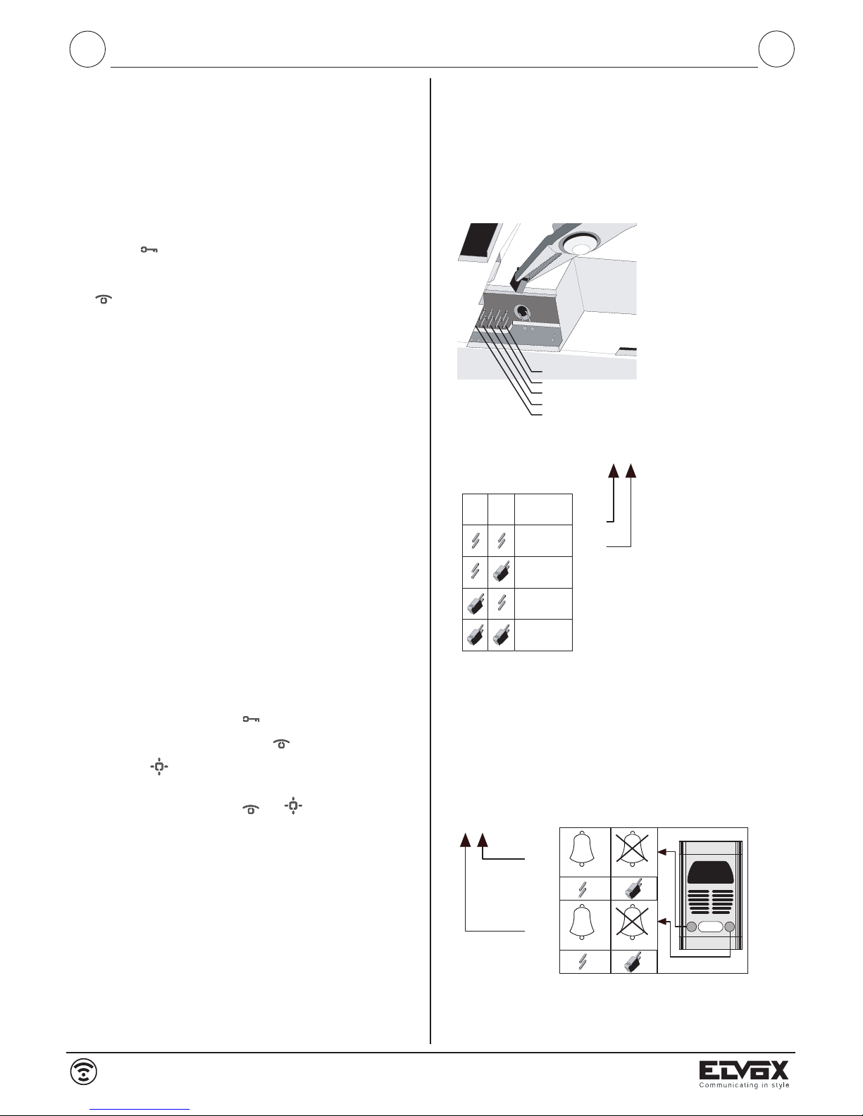
Quando nell’impianto è
presente più di un monitor
è necessario identificare i
monitor con un codice diverso. Il codice di identificazione viene assegnato
tramite l’inserimento dei
ponticelli nei contatti 1 e 2
(ID0 e ID1) come indicato
in figura.
ID 0
ID 1
12
ID1 ID0
MONITOR
n°1
n°2
n°3
n°4
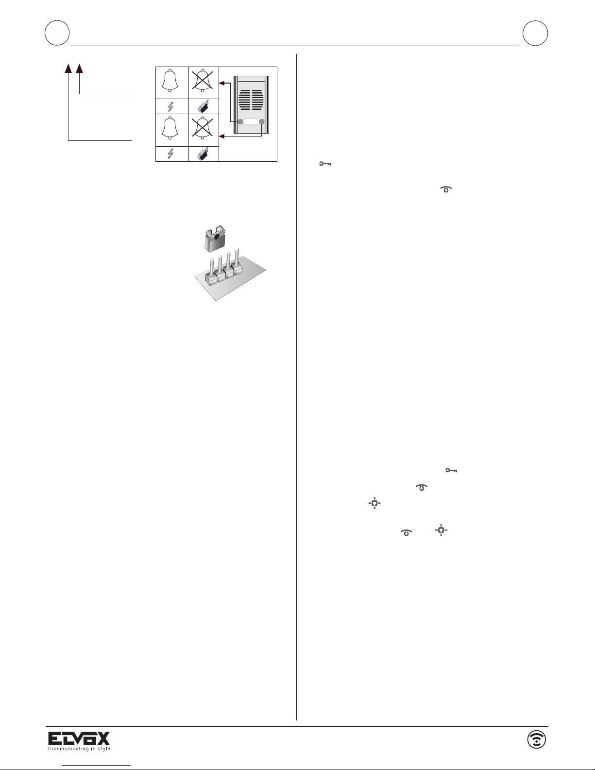
Apertura serratura
Togliendo il ponticello del contatto 3 dal monitor è possibile aprire la
serratura sempre, con monitor acceso o spento. Inserendo il ponticello, dal monitor è possibile aprire la serratura solo dopo che il
monitor è stato chiamato.
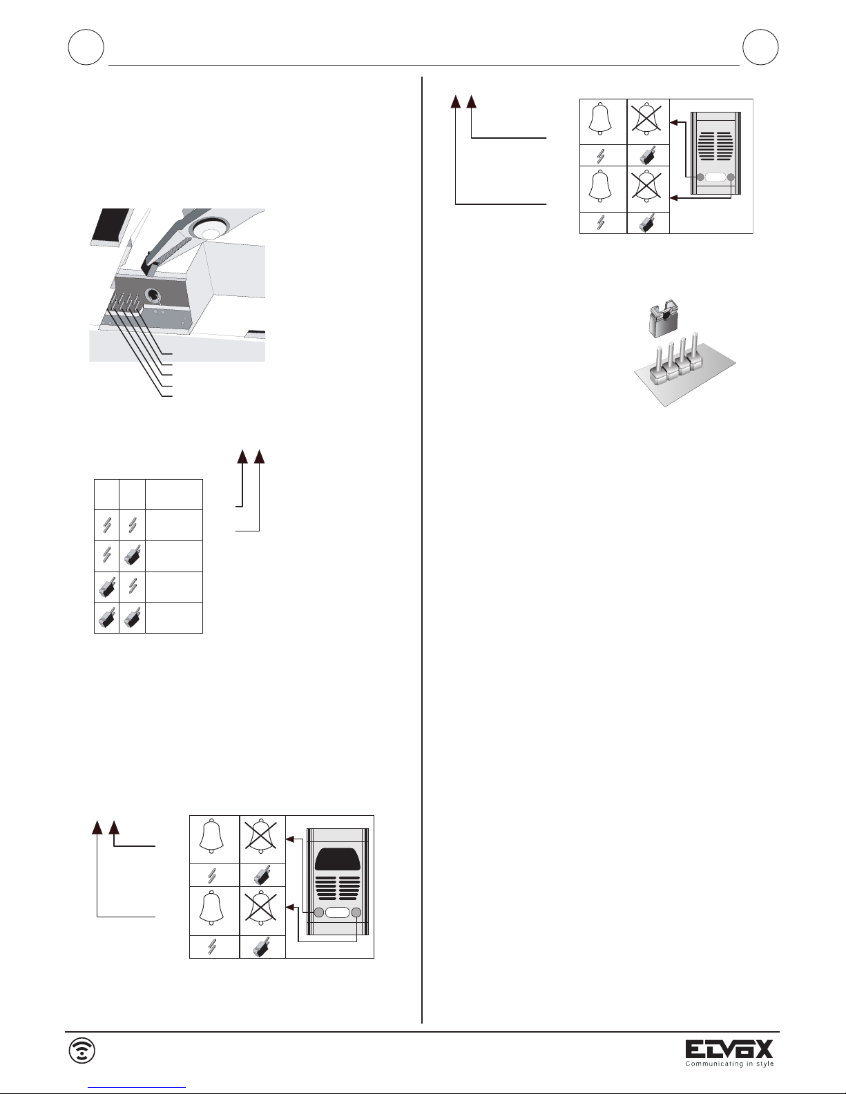
Associazione pulsante di chiamata da targa
Per associare il pulsante della targa con il quale chiamare e accendere il monitor agire sui contatti 4 e 5: il contatto 4 per il pulsante di
destra o 1° pulsante della targa e il contatto 5 per il pulsante di sinistra o 2° pulsante. Inserendo i ponticelli si esclude la chiamata, invece togliendoli si permette la chiamata e l’accensione del monitor.
CH2
CH1
45
Il funzionamento del monitor
è controllato dal settaggio di
5 contatti presenti sul retro
del monitor. Inserire o
togliere i
ponticelli forniti con il monitor per attivare le funzioni.
La programmazione va effettuata prima di alimentare
l’impianto.
Codice di identificazione monitor.
MORSETTI DEL MONITOR ART. 6358
1, 2) Linea BUS
3, 4) Collegamento suoneria supplementare Art. 860A (vedi
variante 1).
12, 13) Alimentazione supplementare con Art. 6923 (morsetto
12=positivo)
V3, M) Collegamento per pulsante chiamata fuoriporta.
2/16
6358
I
Page 3
GB
INSTALLAZIONE DEL MONITOR (fig. 1-2 pag 11)
- Scegliere il luogo per installare il monitor, lontano da fonti luminose,
di calore e di disturbo elettrico.
- Fissare alla parete la piastra di aggancio del monitor con i tasselli in
dotazione a metri 1,40 dal pavimento al bordo inferiore della piastra
stessa.
- E' prevista la foratura per fissare la piastra ad una scatola da incasso
rettangolare a tre moduli.
- Eseguire i collegamenti sulla morsettiera del monitor seguendo gli
schemi.
- Inserire il monitor seguendo il senso delle frecce 1 e 2.
- Per togliere il monitor dalla piastra di aggancio, agire con un cacciavite sulla linguetta di sicurezza ed estrarlo seguendo in senso inverso le frecce 1 e 2.
Si può trasformare il monitor in versione da tavolo utilizzando l'apposito
kit di trasformazione Art. 661A (fig. 4 pag. 11)
COLLEGAMENTI
I due fili di collegamento tra alimentatore e monitor possono essere
invertiti tra loro.
- La sezione consigliata dei 2 conduttori è di 0,75 mm² binato
(twistato). Se il cavo non presenta tali caratteristiche, non si
garantisce quanto descritto nel seguito.
- L'impianto è garantito per un buon funzionamento con una dis-
tanza massima tra alimentatore e monitor di 100 m.
- L'impianto è garantito per un buon funzionamento con una dis-
tanza massima tra alimentatore e telecamera di 100 m.
- Comunque la distanza complessiva tra monitor e telecamera non
deve essere superiore a 120 m.
- La serratura elettrica collegata all'impianto dovrà avere un assor-
bimento massimo di 1A alla tensione di 12V.
- Disturbi o scariche elettriche possono ripercuotersi sul buon
funzionamento delle apparecchiature.
TEMPI DI FUNZIONAMENTO
Il monitor, la telecamera, la serratura e servizi ausiliari devono funzionare con i seguenti cicli di intermittenza.
Ciclo accensione monitor e telecamera:
90 secondi massimi acceso, 90 secondi spento
Ciclo serratura:
30 secondi massimi attiva, 150 secondi disattiva
Ciclo servizi ausiliari
90 secondi massimi attivo, 90 secondi disattivo.
CH2
CH1
45
STABILIZZAZIONE SEGNALE VIDEO
Nel caso in cui l’immagine rappresentata nel videocitofono fosse distorta, spostare il ponticello posto sulla piastra di fissaggio (R684,
R682) del videocitofono, in una delle posizioni alternative “B” o “C”.
A
B
C
Negli impianti dove sono presenti più
videocitofoni collegati in serie, spostare
il ponticello solo dell’ultimo videocitofono nella posizione “B” o “C” e mantenere gli altri ponticelli degli altri
videocitofoni nella posizione “A”.
Negli impianti con più videocitofoni collegati tra di loro a stella, spostare il ponticello dei videocitofoni con l’immagine
distorta nella posizione “B” o “C”.
Video door entry unit with 3.5” colour flat screen 6358, are to be used
as a supplementary video door entry unit in 2-Wire video door entry
kits series 682x.
OPERATION
Carry out connections as described in this leaflet. When entrance
panel push-button is pressed, a call signal is heard on monitor (and
faintly also in the speech unit). The monitor comes on immediately
showing a clear image of the caller. Lift the handset to communicate
with the caller. If , on calling, the handset is already unkooked, the
audio connection is immediately established.
If required operate the electric lock by pressing proper push-button
. The monitor turns off after nearly 30'' (adjustable on the panel
from 30 to 90 seconds). The installation can be switched on by pres-
sing the push-button with the symbol , thus allowing an external view when required.
When two cameras are installed, both cameras are cyclically activated on pressing the push-button.
The following item is designed for use with hearing aids used by hearing impaired people. To activate it, select the “T” position on the
hearing aid.
TECHNICAL CHARACTERISTICS OF MONITOR TYPE 6358
- Surface wall-mounted monitor in ABS.
- Back plate and expansion plugs or 3 module back box for surface
wall-mounting.
- TFT LCD 3,5” screen for type 6358.
- Electronic circuit on interchangeable cards
- Standard video signal PAL (6358)
- Operating temperature: 0° to +40° C
- Electronic chime
- Input for outdoor call with ton different from the entrance panel call.
- Output for additional chime Art. 860A
- Supply voltage from the bus.
- Input for additional power supply (type 6923), if the installation is
configurated for the simultaneous switching on of two monitors.
- Configuration (through jumpers) to disable the chime from one o
more entrance panel push-buttons.
- Configuration (through jumpers) to block the lock activation when
the monitor is switched off.
- External dimensions: 204x220x74
CONTROLS (Fig. 3, Page 11)
- Chime volume adjustment by means of cursor "A"
- Brightness control: through knob "B"
- Contrast control: through knob "C"
- Push-button for electric lock release
- Autoswitching push-button
- Push-button for 1st auxiliary service (allows activation of 1st
relais type 682R).
- Pressing push-buttons and at the same time, the 2nd
auxiliary service (allows activation of 2nd relais type 682R).
- LED for exlusion of chime "D". It lights up with a steady light when
the chime has been excluded by using the "A" cursor and it flashes when there is a conversation in progress on the installation
("engaged" signalling).
- LED for open door "E". When using only an entrance panel the
LED remains lit steadily when the door is open. When two doors
are installed, it remains lit steadily when both door locks are open.
On the contrary if only one of the doors is open, the LED flashes
once for the first door, twice for the second door.
3/16
6358
I
Page 4
GB
MONITOR INSTALLATION (FIG. 1-2, Page 11)
- The monitor should be installed far away from sources of light,
heat and electrical disturbances.
- Fix metal hooking plate to the wall with fixing screws supplied,
keeping top of panel at 1,40 m. from ground level.
- A drilling is forseen in order to fix the plate to a module flush-
mounted back box.
- Carry out connections on monitor terminal block following the dia-
grams.
- Hook the monitor following the arrow 1 and 2 direction .
- To remove the monitor from the hooking plate, operate with a
screwdriver on the security lock and remove it following the arrows 1 and 2 in the opposite direction.
The monitor can be transformed into desk-top version by using the
proper conversion kit type 661A (Fig. 4, page 11).
CONNECTIONS
The two connecting wires between power supply and monitor can
be inverted.
- The advised section for the two conductors is of 0,75 mm² (twi-
sted pair). The following features cannot be guaranted if the section is different.
- The installation is guaranted for a good operation with 100 m ma-
ximum distance from the power supply to the monitor.
- In any case the maximum distance between the camera and the
monitor must not exceed 120 m.
- The electric lock connected to the installation must have a maxi-
mum of 1A power consumption with 12V voltage.
- Humming sounds or electrical discharges may affect the appliance
good operation.
Operating dwell time:
The monitor, camera, door lock and auxiliary services mut operate
according to the following intermittent cycles.
Monitor and camera activation cycle:
max. 90 seconds activated, 90 seconds deactivated
Door lock cycle:
max. 30 seconds activated, 150 seconds deactivated
Auxiliary service cycle:
max. 90 seconds activated, 90 seconds deactivated
PROGRAMMING OF MONITOR TYPE 6358
2
3
5
4
1
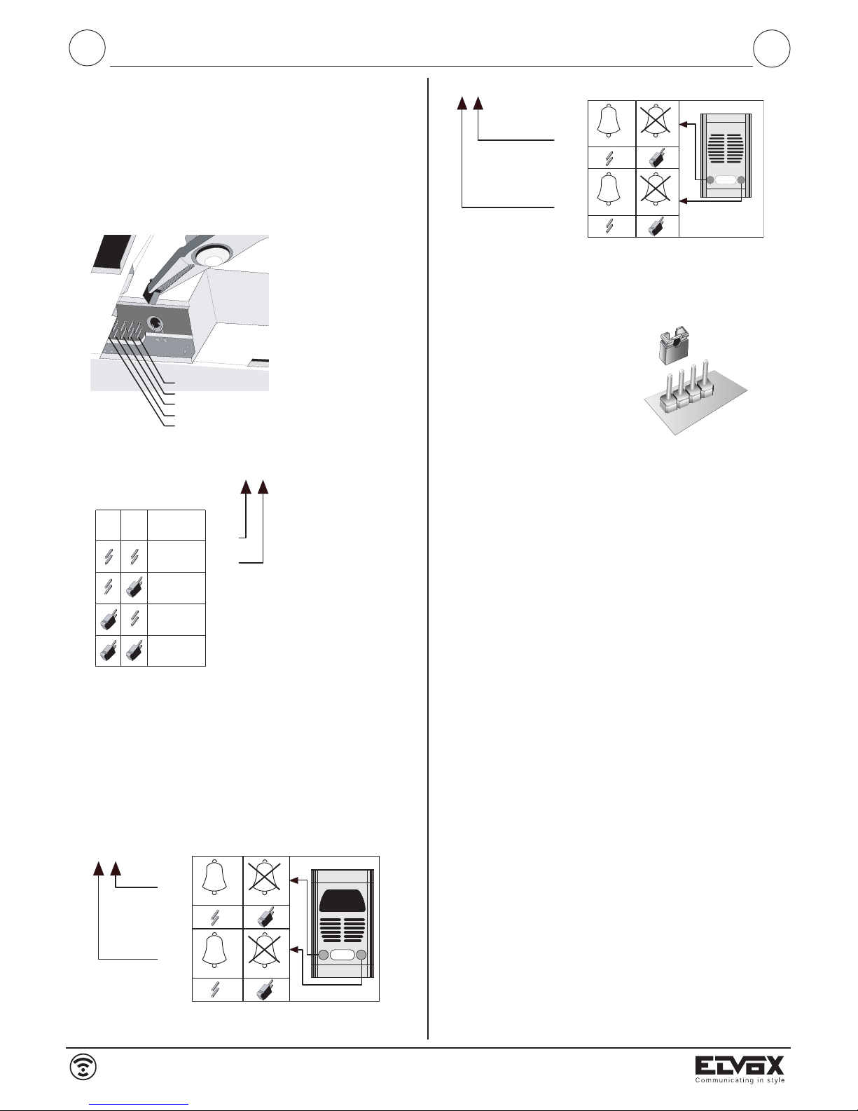
When on the intallation
there is more than one monitor it is necessary to
identify the monitor with a
different code. The identification code is assigned by
inserting the jumpers in
contacts 1 and 2 (ID0 and
ID1) as indicated in the figure.
ID 0
ID 1
12
ID1 ID0
MONITOR
n°1
n°2
n°3
n°4
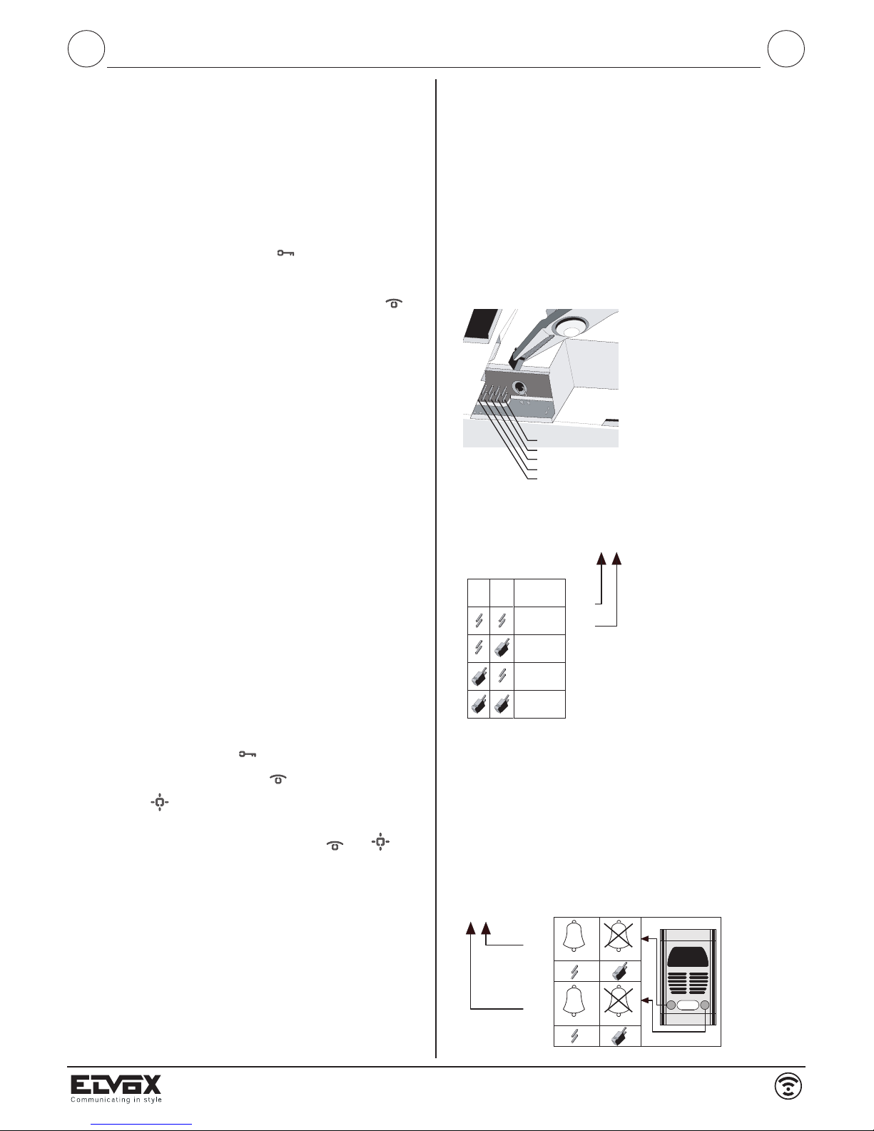
Lock release
Removing contact 3 from the monitor it is possible to open the door
lock always, with monitor switched off or switched on. Inserting the
jumper, it is possible to release the door lock from the monitor only
after the call.
Association of call push-button from the entrance panel
To associate the entrance panel push-button with which to call and
switch on the monitor, operate on contacts 4 and 5: contact 4 for the
right hand panel push-button or 1° push-button and contact 5 for the
left hand push-button or 2° push-button. Inserting the jumpers the
call is excluded, removing them the call and the monitor activation is
enabled.
CH2
CH1
45
A
B
C
VIDEO SIGNAL STABILISATION
If an image on the monitor is misshaped, displace jumper, placed on
the monitor fixing plate (R684, R682), to one of the following alternative positions “B” or “C”.
The operation of monitor is
managed by the 5 contact
setting on the back of monitor. To activate the functions insert or remove the
jumpers supplied with monitor.
Programming must be carried out before powering
the installation.
Monitor identification code
On installations where several monitors are connected in series between
them, place only the jumper of last
monitor to the “B” or “C” position
and kepp the other jumpers of other
monitors in the “A” position.
On installations with more monitors
connected in star configuration,
place the jumper to the “B” or “C”
position only on the monitor with misshaped image.
CH2
CH1
45
TERMINALS OF MONITOR TYPE 6358
1,2) BUS Line
3,4) For connection of additional chime type 860A (see variation
1)
12, 13) Additional power supply art. 6923 (terminal 12 = positive)
V3, M) connection for outdoor call push-button.
4/16
6358
GB
Page 5
F
Le portier vidéo avec écran plat 3,5” couleurs 6358, sont à utiliser en
tant que portier vidéo supplémentaire dans les kits portiers vidéo 2
fils série 682x.
PRINCIPE DE FONCTIONNEMENT
Effectuer l'installation selon les instructions indiquées dans le présent
feuillet. Lorqu'on on appuie sur un bouton-poussoir de la plaque de
rue, on entend un signal acoustique dans le moniteur (et faiblément
même dans le poste externe). L'écran s'allume immédiatement et
l'image du sujet pris apparaît clairement. Pour communiquer avec
l'éxterieur il suffit de soulever le combiné. Si au moment de l’appel le
combiné est déjà soulevé, la connection audio sera immédiatement
établie. Éventuellement on peut actionner la gâche électrique en ap-
puyant sur le poussoir avec le symbole . Lorsqu' environ 30 secondes sont passés (réglables dans la plaque de rue de 30 à 90
secondes) le moniteur s'éteint. L'installation peut être enclenchée dès
l'intérieur en appuyant sur le bouton-poussoir avec le symbole ,
en permettant ainsi le contrôle de l’extérieur à n’importe quel moment.
Si l’on a installé deux plaques de rue, la pression du bouton-poussoir
d’enclenchement active cycliquement les deux caméras.
L'article qui suit est prédisposé pour l'emploi avec les appareils
acoustiques des personnes malentendantes. Pour l'activer, sélectionner la position “T” de l’appareil acoustique.
CARACTÉRISTIQUES TECHNIQUES DU MONITEUR ART. 6358
- Moniteur pour montage mural en saillie en ABS.
- Plaque d'acrochage et vis à goujons pour le montage mural en
saillie ou par l'intermédiare du boîtier à 3 modules.
- TFT LCD 3,5” pour Art. 6358
- Circuit électronique sur cartes interchangeables.
- Signal vidéo standard PAL (6358)
- Température de fonctionnement de 0° à + 40° C
- Sonnerie électronique
- Entrée pour appel porte palière avec son différent de l'appel de la
plaque
- Sortie pour sonnerie supplémentaire Art. 860A
- Alimentation donnée par le bus
- Entrée pour l'alimentation supplémentaire (Art. 6923) lorsque
l'intallation est configurée pour permettre l'enclenchement de plus
de deux moniteurs simultanément.
- Configuration au moyen de pontets pour la dévalidation de la sonnnerie depuis un ou plusieurs boutons-poussoirs de la plaque de
rue.
- Configuration par l'intermédiare de pontets pour bloquer
l'activation de la gâche lorsque le moniteur est éteint.
- Dimensions externes: 204x220x74 mm.
Réglages (Fig. 3, page 11)
- Réglage à curseur du volume de la sonnerie " A "
- Réglage de la luminosité à travers de la poignée " B "
- Règlage du contrast à travers de la poignée " C "
- Poussoir commande gâche
- Poussoir autoallumage installation
- Poussoir pour 1er service auxiliare (il permet l'activation du
relais Art. 682R).
- En appuyant simultanément sur les poussoirs et on
active le 2ème service auxiliare et l'activation du relais Art. 682R.
- LED sonnerie exclue " D ". Lorsque la sonnerie a été exclue par le
curseur " A " la LED s'allume avec lumière fixe et clignote lorsque
dans l'installation une conversation est déjà en cours (signalisation
: " occupé ").
BORNES DU MONITEUR ART. 6358
1,2) Ligne BUS
3,4) Raccordement sonnerie supplémentaire Art. 860A (voir va-
riante 1).
12, 13)Alimentation supplémentaire avec Art. 6923 (borne 12 = po-
sitif)
V3, M) Raccordement pour boutton-possoir appel porte palière
PROGRAMMATION MONITEUR ART. 6358
2
3
5
4
1
Quand dans l'installation il y a
plus d'un moniteur il est nécessaire d'identifier les moniteurs
avec un code différent. Le code
d'dentification est assigné au
moyen de l'insertion des pontets dans les contacts 1 et 2
(ID0 et ID1) comme indiqué
dans la figure.
ID 0
ID 1
12
ID1 ID0
MONITOR
n°1
n°2
n°3
n°4
Ouverture gâche
Lorsqu'on enlève le pontet du contact 3 depuis le moniteur il est possible d'ouvrir toujours la gâche, avec moniteur éteint our enclenché.
En insérant le pontet il est possible d'ouvrir la gâche depuis le moniteur seulement après que le moniteur a été appelé.
Association bouton-poussoir d'appel depuis la plaque de rue
Pour associer le bouton-poussoir de la plaque avec laquelle appeler
et allumer le moniteur agir sur les contacts 4 et 5: le contact 4 pour
le poussoir droit de la plaque de rue ou 1° bouton-poussoir et contact 5 pour le bouton-poussoir à gauche ou 2° bouton-poussoir. En
insérant les pontets on exclut l'appel, au contraire en les enlevant on
permet l'appel et l'allumage du moniteur.
CH2
CH1
45
Le fonctionnement du moniteur est geré para la programmation de 5 contacts présents
à l'arrière du moniteur. Pour
activer les fonctions insérer ou
enlever les pontets fournis
avec le moniteur.
La programmation doit être
effectuée avant d'alimenter
l'installation.
Code d'dentification du moniteur
- LED porte ouverte " E ". Avec seulement une plaque de rue, la LED
reste allumée avec une lumière fixe pendant le temps dans lequel
la porte est ouverte. Avec deux plaques de rue, la LED reste allumée avec lumière fixe lorsque les deux portes sont ouvertes, si, au
contraire, seulement une porte est ouverte, la LED clignote avec 1
clignotement pour la première porte et deux clignotements pour la
deuxième porte.
5/16
6358
F
Page 6

F
INSTALLATION DU MONITEUR (Fig. 1-2, page 11)
- Choisir l'endroit idéal pour installer le moniteur, à bonne distance
de toute source de lumière, de chaleur et de dérangement électrique.
- Fixer la plaque d'accrochage du moniteur à la paroi avec les vis à
goujons fournis dans l'emballage à 1,40m du sol au bord inférieur
de la plaque.
- On prévoit le percement pour fixer la plaque à une boîte à encastrer rectangulaire à trois modules.
- Effectuer les raccordements sur le boîtier du moniteur en suivant
les schémas.
- Insérer le moniteur en suivant la direction des flèches 1 et 2.
- Pour enlever le moniteur de la plaque d'accrochage, effectuer une
légere pression avec un tournevis sur le crochet de sécurité et
l'extraire en suivant la direction contraire des flèches 1 et 2.
On peut transformer le moniteur en version de table en utilisant le kit
de transformation approprié Art. 661A (Fig. 4, page 11).
RACCORDEMENTS
Les deux fils de raccordmenet entre l'alimentation et le moniteur peuvent être intervertis entre eux.
- Il est conseillé d'utiliser 2 conducteurs avec section 0,75 mm²
(paire twistée). Si le câble n'a pas cette section on ne garantit pas
les caracteristiques qui suivent.
- L'installation est garantie pour un bon fonctionnement avec une
distance maximum entre l'alimentation et le monitor de 100 m.
- La distance totale entre moniteur et caméra ne doit pas être supérieure à 120 m.
- La gâche électrique connectée à l'installation doit avoir une absorption maximum d' 1A à la tension de 12V.
- Bourdonnements et décharges électriques peuvent influencer le
bon fonctionnement des appareils.
Temps de fonctionnement:
Le moniteur, la caméra, la gâche et les services auxiliaires doivent
fonctionner selon les cycles d'intermittance suivants:
Cycle enclenchement moniteur et caméra
90 secondes (max) activé, 90 secondes désactivé
Cycle gâche
30 secondes activé (max), 150 secondes désactivé
Cycle services auxiliaires
90 secondes activé (max), 90 secondes déactivé
Die Videotürsprechmonitore mit 3,5“-Farb-Flachbildschirm Art. 6358,
sind als zusätzliche Videotürsprechmonitore in den Video-Türsprechanlagensets der Due Fili-Serie 682x zu verwenden.
BETRIEB
Die Anlage nach den beiliegenden Anweisungen installieren. Drückt
man die Klingeltaste der Video-Türsprechanlage, hört man ein akustisches Signal am Monitor (und schwach auch in der Außenstelle).
Der Monitor schaltet sich sofort ein und zeigt ein scharfes Bild vom
Rufenden. Zum Sprechen den Hörer abheben. Wenn beim Ruf der
Hörer schon abgehoben ist, wird die Sprechverbindung sofort durchgeführt. Eventuell den Türöffner durch Drücken der entsprechenden Taste betätigen. Nach Ablauf von 30 Sekunden (regelbar am
Klingeltableau von 30 bis max. 90 Sekunden) schaltet sich der Monitor aus. Die Anlage kann auch jederzeit von innen, durch Drücken
der Taste mit dem Symbol am Monitor, eingeschaltet werden. Sollten zwei Kameras installiert sein, so aktiviert der Druck der Selbsteinschalttaste zyklisch die zwei Kameras.
Der folgende Artikel ist für die Verwendung mit den Hörgeräten von
Hörgeschädigten vorgesehen. Zur Aktivierung bitte die Stellung „T”
des Hörgeräts auswählen.
TECHNISCHE EIGENSCHAFTEN DES MONITORS ART. 6358
- Aufputz-Videohaustelefon aus ABS
- Montageplatte und Schrauben mit Dübel für die Wandbefestigung
- 3,5” TFT-LCD
- Elektronischer Schaltkreis auf auswechselbaren Platinen.
- Standard Video-Signal PAL
- Betriebstemperatur von 0° bis + 40° C
- Elektronisches Läutwerk
- Eingang für Etagenruf mit Rufunterscheidung
- Ausgang für Zusatzläutwerk Art. 860A
- Stromversorgung vom Bus.
- Eingang für zusätzliche Stromversorgung (Art. 6923) falls die Anlage so konfiguriert ist, dass mehr als zwei Monitore gleichzeitig
einschalten können.
- Konfiguration (durch Jumper) um die Klingel von einer oder mehreren Klingeltableautasten zu deaktivieren.
- Konfiguration (durch Jumper) um die Türöffnerbetätigung bei ausgeschaltetem Monitor zu deaktivieren.
- Abmessungen: 204x220x74 mm
REGELUNGEN (Abb. 3, Seite 11)
- Schiebeschalter für Lautstärke: "A"
- Helligkeitsregelung durch Knopf: "B"
- Kontrastregelung durch Knopf: "C"
- Türöffnertaste
- Selbsteinschalttaste
- Taste für 1. Zusatzfunktion (ermöglicht die Aktivierung des
1. Relais des Art. 682R).
- Durch gleichzeitiges Drücken der Tasten und , wird
die 2. Zusatzfunktion über das 2. Relais des Art. 682R aktiviert.
- LED rot für Anzeige Rufabschaltung "D". Diese LED leuchtet im
Dauerlicht auf, wenn mit dem Schiebeschalter "A" der Rufton abgeschaltet wurde, und blinkt, wenn in der Anlage schon ein Gespräch durchgeführt wird ("Besetzt"-Anzeige).
STABILISATION DU SIGNAL VIDEO
Lorsqu’une image répresentée dans le moniteur est déformée, déplacer le pontet, situé à l’arrière de la plaque de fixation (R684, R682)
du moniteur, sur une des positions alternatives ”B” ou “C”.
A
B
C
Dans les installations avec plusieurs moniteurs raccordés en série, placer sur la
position “B” ou “C” seulment le pontet du
dernier moniteur et maintenir les pontets
des autres moniteurs dans la position “A”.
Dans les installations avec plusierus moniteurs raccordés en étoile, placer le pontet
sur la position “B” ou “C” dans les moniteurs avec image déformée.
CH2
CH1
45
6/16
6358
D
Page 7

D
- LED grün für Tür offen. In Anlagen mit nur einem Klingeltableau,
leuchtet die LED im Dauerlicht auf, wenn die Tür offen ist. Sind
zwei Klingeltableaus vorhanden, leuchtet die LED im Dauerlicht
auf, wenn beide Türen offen sind. Wenn nur die erste Tür geöffnet ist, blinkt die LED einmal, ist die zweite Tür geöffnet, blinkt die
LED zweimal.
KLEMMEN DES MONITORS ART. 6358
1,2) BUS-Linie
3,4) Anschluss Zusatzläutwerk Art. 860A (siehe Sonderschaltung
1)
12, 13) Zusatzversorgung für Monitor mit Netzgerät Art. 6923
(Klemme 12 positiv)
V3, M) Anschluss für Etagenruftaste
PROGRAMMIERUNG DES MONITORS ART. 6358
2
3
5
4
1
Wenn in der Anlage mehr
als 1 Monitor eingebaut
wird, ist es notwendig, die
Monitore mit einem verschiedenen Code zu identifizieren.
Der Identifizierungscode
wird durch das Einsetzen
der Brücken in den Kontakten 1 und 2 (ID0 und
ID1) wie im Schaltplan gezeigt, zugewiesen.
ID 0
ID 1
12
ID1 ID0
MONITOR
n°1
n°2
n°3
n°4
TÜRÖFFNUNG
Durch Entfernen der Brücke des Kontakts 3, ist es immer möglich
die Tür mit eingeschaltetem oder ausgeschaltetem Monitor zu öffnen,. Durch Einsetzen der Brücke kann der Türöffner nur betätigt werden, nachdem der Monitor angerufen oder selbst aktiviert wurde.
ZUWEISUNG DER RUFTASTE VOM KLINGELTABLEAU
Die Zuordnung der Klingeltaste und des entsprechenden Monitors
erfolgt anhand der Kontakte 4 und 5: Kontakt 4 für die rechte oder
erste Taste des Klingeltableaus und Kontakt 5 für die linke oder
zweite Taste. Durch Einsetzen der Brücken, wird der Ruf ausgeschlossen, durch Entfernen dieser Brücken, wird der Monitorruf und
die Einschaltung freigegeben.
CH2
CH1
45
A
B
C
AUSGLEICH DES VIDEOSIGNALS
Wenn das Bild eines Monitors verzerrt ist, die Brücke, die sich auf
der Monitorbefestigungsplatte (R684, R682) befindet, auf eine der
alternativen Stellungen „B“ oder „C“ stecken.
Der Betrieb des Monitors ist durch
die Programmierung von 5 Kontakten, die sich auf der Monitorrückseite befinden, gesteuert. Die
mit dem Monitor mitgelieferten
Brücken einstecken oder abnehmen um die Funktionen zu aktivieren.
Die Programmierung muss vor der
Versorgung der Anlage durchgeführt werden.
IDENTIFIZIERUNGSCODE DES MONITORS
Bei Anlagen mit mehreren Monitoren
in Serienschaltung, nur die Brücke
des letzten Monitors auf “B“ oder „C“
setzen und die Brücken der anderen
Monitore in Stellung “B“ oder “C”
stecken lassen.
Bei Anlagen mit mehreren Monitoren
in Sternschaltung, nur beim Monitor
mit verzerrtem Bild die Brücke in
Stellung „A“ stecken.
EINBAU DES MONITORS (Abb. 1-2, Seite 11)
- Der Monitor ist an einem Ort zu installieren, an dem sich keine
Licht- und Wärmequellen sowie elektrische Störquellen befinden.
- Die Befestigungsplatte des Monitors an der Wand mit den mitgelieferten Schrauben und Dübeln befestigen: - Unterkannte 1,40 m
vom Boden.
- Eine Bohrung ist für die Befestigung auf einem rechteckigen 3Modul-UP-Gehäuse vorgesehen. - Die Anschlüsse auf der
Klemmenleiste des Monitors gemäß den Schaltbildern durchführen. - Den Monitor in Pfeilrichtung 1 und 2 einsetzen.
- Um den Monitor von der Montageplatte abzunehmen, mit einem
Schraubenzieher die Verriegelung lösen und in umgekehrter Pfeilrichtung 1 und 2 den Monitor abnehmen. Es ist möglich den Monitor unter Verwendung des Umbausatzes Art. 661A in ein
Tischgerät umzubauen (Abb. 4, Seite 11).
ANSCHLÜSSE
Die zwei Anschlussdrähte zwischen dem Netzgerät und dem Moni-
tor können miteinander vertauscht werden.
- Der empfohlene Querschnitt der 2 Adern beträgt 0,75 mm² (Twisted Pair). Wird ein anderes Kabel verwendet, kann folgendes
nicht gewährleistet werden:
- Die Anlage garantiert einen guten Betrieb mit max. 100m Abstand
zwischen Netzgerät und Monitor.
- Auf jeden Fall darf der Gesamtabstand zwischen Monitor und Kamera 120m nicht überschreiten.
- Der an der Anlage angeschlossene elektrische Türöffner darf max.
1A bei 12V Gleichspannung aufnehmen.
- Störungen und elektrische Entladungen können den optimalen Betrieb der Anlage beeinflussen.
Betriebsdauer
Monitor, Kamera, Türöffner und Zusatzfunktionen müssen in Bezug
auf folgende periodische Zyklen arbeiten.Monitor und Kamera Einschaltzyklus:
Max. 90 Sekunden aktiviert, 90 Sekunden deaktiviert
Türöffnerzyklus:
Max. 1 Sekunde aktiviert, 5 Sekunden deaktiviert
Zusatzfunktionszyklus:
Max. 90 Sekunden aktiviert, 90 Sekunden deaktiviert.
CH2
CH1
45
7/16
6358
D
Page 8

E
El videoportero con pantalla plana 3,5” en color 6358, se utilizan
como videoportero adicional en los kits de videoporteros de 2 hilos
de las series 682x.
PRINCIPO DE FUNCIONAMIENTO
Efectuar la instalación siguiendo las intrucciones adjuntas. Presionando el pulsador de la placa se oye una señal acústica en el monitor (y debilmente también en el aparato externo) que inmediatamente
se iluminará mostrando de manera clara el sujeto captado por la cámara. Para conversar con el exterior descolgar el microteléfono. Si al
momento de la llamda el microteléfono ya está descolgado, la conexión audio será establecida en seguida.
Eventualmente activar la cerradura eléctrica presionando el pulsa-
dor con el símbolo . Pasado un tiempo de cerca 30'' (regulable
en la placa de 30 a 90 segundos) el monitor se apagará. La instalación se puede encender también desde el interior pulsando el pulsa-
dor con el símbolo , permitiendo así el control del exterior en
cualquier momento. Cuando en la instalación hay dos placas, la presión del pulsador de encendido activa cíclicamente las dos cámaras.
El siguiente artículo está preparado para su utilización con los aparatos de audición para sordos. Para activarlo, hay que seleccionar la
posición “T” del aparato de audición.
CARACTERÍSTICAS TÉCNICAS DEL MONITOR ART. 6358
- Monitor de superficie en ABS; color estandard.
- Plancha de enganche y tacos o caja de 3 módulos para la fijación
a la pared.
- TFT LCD 3,5” para Art. 6358.
- Circuito eléctronico con fichas intercambiables.
- Señal vídeo estándard PAL (6358)
- Temperatura de funcinamiento de 0° a + 40° C
- Timbre electrónico
- Entrada para llamada puerta apartamiento con sonido diferente
de la llamada de la placa.
- Salida para timbre suplementario Art. 860A
- Alimentación dada por el bus.
- Entrada para alimentación suplementaria (Art. 6923), cuando la
instalación está configurada para permitir el encendido simultáneo de más de un monitor.
- Configuración (por medio de puentes) para deshabilitar el timbre
desde uno o más pulsadores de la placa.
- Configuración (por medio de puentes) para bloquear la activación
de la cerradura con monitor apagado.
- Dimensiones máximas externas: 204x220x74
Controles (Fig. 3, pág. 11)
- Control tonalidad timbre : Cursor "A "
- Control luminosidad por medio de la manopla " B "
- Control contraste por medio de la manopla "C"
- Pulsador mando cerradura .
- Pulsador autoencendido instalación
- Pulsador para 1er servicio auxiliar (permite la activación
del relé Art. 682R).
Presionando simultáneamente los dos pulsadores ed
, se activa el 2do servicio auxiliar (permite la activación del relé
Art. 682R).
- LED "timbre excluído" "D". Se enciende con luz fija cuando el timbre viene excluído por medio del cursor "A" y relampaguea
cuando en la instalación hay ya una conversación en acto (señalización de ocupado).
- LED "puerta abierta" "E". Cuando en la instalación hay sólo una
placa queda encendido con luz fija cuando la puerta está abierta.
Con dos placas permanece encendido con luz fija cuando las dos
puertas están abiertas, en cambio si solamente una puerta está
abierta el LED relampaguea una vez para la primera puerta y dos
veces para la segunda puerta.
PROGRAMACIÓN MONITOR ART. 6358
2
3
5
4
1
Cuando en la instalación
hay más de 1 monitor es
necesario identificar losmonitores con un código diferente. El código de
identificación viene atribuído por medio de la inserción de los puentes en
los contactos 1 y 2 (ID0 y
ID1) como indicado en la figura.
ID 0
ID 1
12
ID1 ID0
MONITOR
n°1
n°2
n°3
n°4
Apertura de la cerradura
Para asociar el pulsador de la placa con el cual llamar o encender el
monitor actuar en los contactos 4 y 5 : el contacto 4 para el pulsador de derecha de la placa y el contacto 5 para el pulsador de izquierda (si hay alguno). Insertando los puentes se excluye la llamada
y el encendido del monitor.
Asociación pulsador de llamada desde la placa:
Para asociar el pulsador de la placa con el cual llamar y encender el
monitor obrar sobre los contactos 4 y 5: el contacto 4 para el pulsador de derecha de la placa o 1° pulsador y el contacto 5 para el
pulsador de izquierda o 2° pulsador, en cambio quitando los mismo
puentes se permite la llamada y el encendido del monitor.
CH2
CH1
45
El funcionamiento del monitor viene administrado por
la programación de 5 contactos presentes detrás del
monitor. Insertar o quitar los
puentes suministrados con
el monitor para activar las
funciones.
La programación debe ser
efectuada antes de alimentar la instalación.
Código de identificación del monitor
BORNES DEL MONITOR ART. 6358
1,2) Línea BUS
3,4)
Conexionado timbre suplementario Art. 860A (ver variación 1).
12, 13) Alimentación suplementaria con Art. 6923 (borne 12 = po-
sitivo)
V3, M) Conexionado para pulsador llamada puerta apartamiento.
8/16
6358
E
Page 9

P
INSTALACIÓN DEL MONITOR (Fig. 1-2, pág. 11)
- Para la instalación del monitor escoger un lugar lejano de fuentes
luminosas, de calor y de interferencias eléctricas.
- Fijar a la pared la plancha de enganche del monitor con los tacos
en dotación a 1,40 m desde el piso al borde inferior de la misma
plancha.
- Se prevee la horadadura para fijar la plancha a una caja de empotre rectangular de tres módulos.
- Efectuar las conexiones en la regletas de conexiones del monitor
siguiendo los esquemas.
- Insertar el monitor siguiendo la dirección de las flechas 1 y 2.
- Para quitar el monitor desde la plancha de enganche, actuar con
un destornillador en la lengüeta de seguridad y extraerlo siguiendo
la dirección contraria a las flechas 1 y 2.
Se puede transformar el monitor en versión de sobremesa utilizando
el kit de transformación apropiado Art. 661A (Fig. 4, pág. 11),
CONEXIONADOS
Los dos hilos de conexión entre alimentador y monitor pueden ser invertidos entre ellos.
- La sección aconsejada de los 2 conductores es de 0,75 mm² (par
twistado). Si el cable no tiene estas características no se puede
asegurar lo que sigue.
- Se asegura un buen funcionamiento de la instalación con una distancia máxima entre alimentador y monitor de 100 m.
- De todos modos la distancia total entre monitor y cámara tendrá
que tener una absorpión máxima de 1A a la tensión de 12V.
- Interferencias o descargas eléctricas pueden influenciar el buen
funcionamiento de los aparatos.
Tiempos de funcionamientos
El monitor, la cámara, la cerradura y los servicios auxiliares deben
funcionar con los siguientes ciclos de intermitencia.
Ciclo de encendido monitor y cámara
90 secundos (máx) activado, 90 segundos desactivado
Ciclo cerradura:
30 segundos (máx) activado, 150 segundos desactivado
Ciclo servicios auxiliares
90 segundos (máx) activado, 90 segundos desactivado
A
B
C
ESTABILIZACIÓN DE LA SEÑAL VÍDEO
Cuando una imágen representada en el monitor está deformada, desplazar el puente, colocado en la plancha de fijación (R684, R682)
del monitor, en una de las posiciones alternativcas “B” o “C”.
En las instalaciones donde hay varios monitores conectados en serie entre ellos, colocar el puente en « B » o « C » solamente
en el último monitor y mantener los puentes de los otros monitores en la posición «
A ».
En las intalaciones con varios monitores
conectados a estrella, colocar el puente en
« B » o « C » solamente nel monitor con
imágen deformada.
O vídeoporteiro com ecrã plano de 3,5” a cores 6358 devem ser utilizados como vídeoporteiro suplementar nos kits de vídeoporteiros
de 2 fios da série 682x.
PRINCIPIO DE FUNCIONAMENTO
Efectuar a instalação conforme as instruções unidas.
Premindo um botão da botoneira ouvir-se-á no monitor um sinal acústico ( e débilmente mesmo no posto externo). O monitor ilumina-se
imediatmente mostrando claramente o sujeito presente diante a telecâmara.
Para conversar com o exterior levantar o punho. Se for necessário
activar o trinco eléctrico premindo o botão adequado .
Decorridos cerca de 30 segundos (reguláveis na botoneira de 30 a 90
segundos) o monitor apagar-se-á. A ligação pode ser feita também
do interior, premindo o botáo com o símbolo , o que possibilita
controlar o exterior em qualquer momento.
Se foram instaladas duas botoneiras, a pressão do botão de acendimento activa cíclicamente as duas telecâmaras.
O seguinte artigo está preparado para ser utilizado com os aparelhos
acústicos dos deficientes auditivos. Para o activar, seleccione a posição “T” do aparelho acústico.
CARACTERÍSTICAS TÉCNICAS DO MONITOR ART. 6358
- Monitor de montagem saliente em ABS.
- Placa de enganche para fixação à parede o através duma caixa
de 3 módulos.
- TFT LCD 3,5” para Art. 6358.
- Circuito electrónico em placas intercambiáveis.
- Sinal video estándard PAL (6358)
- Temperatura de funcionamento de 0° até + 40° C.
- Campainha electrónica.
- Entrada para chamada porta no patamar com som diferente da
chamada da botoneira.
- Saída para campainha suplementar Art. 860A.
- Alimentação pelo bus.
- Entrada para alimentador suplementar (Art. 6923) no caso da instalação ser configurada para permitir o acendimento de mais do
que dois monitores simultâneamente.
- Configuração através pontas para deshabilitar a campainha de um
o mais botóes da placa.
- Configuração através de pontes para bloquear o accionamento
do trinco quando o monitor está desligado.
- Dimensões : 204x220x74 mm.
Controles (Fig. 3, pág. 11)
- Contrôle da intensidade da campainha : cursor " A "
- Controle luminosidade através do punho "B"
- Controle do contraste através do punho "C"
- Botão comando do trinco
- Botão autoacendimento da instalação
- Botão para 1° serviço auxiliar (permite a activação do relé
Art. 682R).
- Premindo simultâneamenteos os botões e activa-se o
2° serviço auxiliar e a activação do relé Art. 682R.
- LED para indicação de "campainha excluida" "D". Se encende
com luz vermellha quando a campainha foi excluida por medio do
cursor "A" e cintila quando na instalação é em curso uma conversação (sinalização de ocupado).
- LED porta aberta "E". Quando na instalaçã há só uma botoneira o
LED permanece aceso com luz fixa quando a porta está aberta.
Quando na istalação há duas botoneiras o LED permanece aceso
quando as duas portas estão abertas, no contrario se a porta
aberta é só uma (das duas), o LED cintila uma vez (só uma cintilação) para a primeira porta ou com duas cintilacões para a segunda porta.
CH2
CH1
45
9/16
6358
E
Page 10
P
INSTALAÇÃO DO MONITOR (Fig. 1-2, pág. 11)
- Para a instalação do monitor escolher un sito afastado das fontes
luminosas, de calor ou de disturbios eléctricos.
- Fixar à parede a placa de enganche do monitor com as calhas
fornecidas a 1,40 m do chao ao bordo inferior da memsa placa.
- Preve-se o furo para fixar a placa a uma caixa de embeber rectan-
gular de três módulos.
- Efectuar as ligações na régua de ligação do monitor seguindo os
esquemas.
- Inserir o monitor seguindo as setas 1 e 2.
- Para quitar o monitor da placa de enganche obrar com uma chave
de parafusos na lingüeta de segurança e extrai-lo seguindo a direcção contraria das setas 1 e 2.
Pode-se transformar o monitor na versão de mesa utilizando o kit
de transformação Art. 661A (Fig. 4, Pág. 11).
LIGAÇÕES
Os dois fios de ligação entre alimentador e monitor podem ser trocados entre si.
- A secção aconselhada dos 2 conductores é de 0,75 mm² (par twistado). Se o cabo não tem estas características não pode-se garantir o descrito a continuação.
- A instalação garante um bom funcionamento com uma distância
máxima de 100 m. entre alimentador e monitor
- De qualquer maneira a distância total entre o monitor e a telecâmara não deve superar os 120 m.
- O trinco eléctrico ligado à instalação deverá ter uma absorção máxima de 1A à tensão de 12V.
- Disturbios o descargas eléctricas podem influir no bom funcionamento da aparelhagem.
Tempos de funcionamento
O monitor, a telecâmara, o trinco e os serviços auxiliares devem funcionar com os seguintes ciclos de intermitência.
Ciclo de acendimento do monitor e telecâmara.
90 segundos (máx) ligado, 90 segundos desligado
Ciclo do trinco:
30 segundos (máx) ligado, 150 segundos desligado
Ciclo serviços auxiliares
90 segundos (máx) ligado, 90 segundos desligado.
PROGRAMAÇÃO DO MONITOR ART. 6358
2
3
5
4
1
Quando na instalação há
mais do que um monitor
é necessário identificar os
monitores com um código diverso. O código de
identificação é assinalado
através da inserção das
pontes nos contactos 1 e
2 (ID0 e ID1) como indica
a figura.
ID 0
ID 1
12
ID1 ID0
MONITOR
n°1
n°2
n°3
n°4
Abertura do trinco
Retirando a ponte do contacto 3 do monitor é possível abrir o trinco
sempre, com monitor aceso o desligado.
Inserindo a ponte, é possível abrir o trinco do monitor só depois o
monitor ser chamado.
Associação botão de chamada da botoneira
Para associar o botão da botoneira com o qual chamar o acender o
monitor obrar nos contactos 4 e 5: o contacto 4 serve para botão de
direita da botoneira ou 1° botão e o contacto 5 para botão de ezquerda ou 2° botão. Inserindo as pontes exclui-se a chamada, no
contrario retirando-as permitem-se a chamada e o acendimento do
monitor.
CH2
CH1
45
A
B
C
ESTABILIZAÇÃO DO SINAL DE VIDEO
Quando a imagem representada num monitor está deformada,
mover a ponte, colocada na placa de fixação (R684, R682) do monitor, em uma das posições alternativas “B” ou “C”.
O funcionamento do monitor é gerido pela programação de 5 contactos
presentes detrás do monitor. Inserir o retirar as pontes fornecidas com o
monitor para activar as funções.
A programação deve ser
efectuada antes de alimentar a instalação.
Código de identificação do monitor
Nas intalações com vários monitores
ligados em série entre si, colocar a
ponte na posição « B » ou « C » só no
último monitor com imagen deformada e deixar as outras pontes na
posição “A”.
Nas instalações com vários monitores ligados a estrêla, colocar a ponte
em « B » ou « C » só nos monitors
com imagem estorvada.
CH2
CH1
45
TERMINAIS DO MONITOR ART. 6358
1, 2) Linha BUS
3, 4) Ligação campainha suplementar Art. 860A (ver variante 1).
12, 13) Alimentação suplementar com Art. 6923 (terminal 12= posi-
tivo)
V3, M) Ligação para botão chamada no patamar.
10/16
6358
P
Page 11

C
BA
D
E
6358
1
1
1
2
2
1
Fig. 3
Fig. 4
1,40
Fig. 1
11/16
Fig. 2
*
SEZIONE CONDUTTORI CONSIGLIATA PER I DUE FILI
CONDUCTOR SECTION ADVISED FOR THE TWO WIRES
SECTION DES CONDUCTEURS CONSEILLÉE POUR LES DEUX FILS
EMPFOHLENER LEITERQUERSCHNITT FÜR DIE ZWEI DRÄHTE
SECCIÓN CONDUCTORES ACONSEJADA PARA LOS DOS HILOS
SECÇÃO CONDUCTORES ACONSELHADA PARA OS DOIS FIOS
VIDEOKIT Art. 68../R e 68../R2 (IN BIANCO E NERO)
VIDEOKIT Type 68../R AND 68../R2 IN BLACK AND WHITE.
KIT VIDÉO Art. 68../R ET 68../R2 EN BLANC/NOIR.
S/W-VIDEOSET ART. 68../R UND 68../R2
KIR VÍDEO Art. 68../R Y 68../R2 EN BLANCO Y NEGRO.
KIT VIDEO Art. 68../R Y 68I… EM BRANCO/PRETO.
DUE FILI DI SEZIONE MINIMA 0,75 PER 100 metri MASSIMI
TWO WIRES WITH MINIMUM SECTION OF 0.75 FOR A MAXIMUM OF 100 METRES.
DEUX FILS AVEC SECTION MINIMALE DE 0,75 POUR UN MAXIMUM DE 100 MÈTRES.
ZWEI DRÄHTE MIT MIN. QUERSCHNITT VON 0,75 MM² BIS MAX.100 M
DOS HILOS DE SECCIÓN MÍNIMA 0,75 PARA UN MÁXIMO DE 100 METROS.
DOIS FIOS DE SECÇÃO MÍNIMA 0,75 PARA UM MÁXIMO DE 100 METROS.
VIDEOKIT ART. 68../RC E 68../RC2 (A COLORI)
VIDEOKIT TYPE 68../RC AND 68../RC2 (COLOUR)
VIDEOKIT ART. 68../RC ET 68../RC2 (EN COULEURS)
FARB-VIDEOSET ART. 68../RC UND 68../RC2
VIDEOKIT ART. 68../RC Y 68../RC2 (EN COLOR)
VIDEOKIT ART. 68../RC E 68../RC2 (A CORES)
CAVO TWISTATO ART. 732H O 732I PER 60 metri MASSIMI
TWISTED CABLE ART. 732H OR 732I FOR A MAXIMUM OF 60 METRES
CÂBLE TWISTÉ ART. 732H OU 732I POUR UN MAXIMUM DE 60 MÈTRES
“TWISTED-PAIR“-KABEL ART. 732H ODER 732I BIS MAX. 60 METER
CABLE TWISTADO ART. 732H O 732I PARA UN MÁXIMO DE 60 METROS.
CABO TWISTADO ART. 732H OU 732I PARA UM MÁXIMO DE 60 METROS.
Page 12

ID=1
PRI
B2 2 1 B1
M
13
V3
1
3
2
4
12
D
CH1=
SCHEMA DI COLLEGAMENTO VIDEOCITOFONO
WIRING DIAGRAM FOR MONITOR
SCHÉMAS DE RACCORDEMENENT POUR MONITEUR
SCHALTPLAN FÜR MONITOR
ESQUEMA DE CONEXIONADO MONITOR
ESQUEMA DE LIGAÇÃO MONITOR
D - PULSANTE PER CHIAMATA FUORIPORTA
PUSH-BUTTON FOR OUTDOOR CALL
POUSSOIR POUR APPEL PORTE PALIÈRE
WOHNTÜRRUFTASTE
PULSADOR LLAMADA PUERTA PARTAMIENTO
BOTÃO PARA CHAMADA NO PATAMAR
N° si171
MONITOR
MONITEUR
Art. 6358
ALIMENTATORE
POWER SUPPLY
ALIMENTATION
NETGERÄT
ALIMENTADOR
Art. 692K
RETE
MAINS
RÉSEAU
NETZ
RED
REDE
Alla targa esterna
To the external entrance panel
À la plaque externe
Zum Externklingeltableau
A la placa externa
À botoneira externa
6358
12/16
*
*
*
Page 13

ID=2
ID=1
ID=3
VIDEO
B1 1 2 B2
PRI
12
4
2
3
1
V3
13
M
M
13
V3
1
3
2
4
12
CH1=
D
CH1=
D
CH1=
D
L
1
4
6P
6S
5
2
+
-
13
12
10
11
4
9
8
SCHEMA DI COLLEGAMENTO CON DUE MONITOR E UN CITOFONO
WIRING DIAGRAM WITH TWO MONITORS AND ONE PHONE
SCHÉMAS DE RACCORDEMENT AVEC DEUX MONITEURS ET UN POSTES
SCHALTPLAN MIT ZWEI MONITOREN UND EIN HAUSTELEFON
ESQUEMA DE CONEXIONADO CON DOS MONITORES Y UN TELEFONO
ESQUEMA DE LIGAÇÃO COM DOIS MONITORES E UN TELEFONE
ALIMENTATORE
POWER SUPPLY
ALIMENTATION
NETGERÄT
ALIMENTADOR
Art. 692K
N° si172
RETE
MAINS
RÉSEAU
NETZ
RED
REDE
D - PULSANTE PER CHIAMATA FUORIPORTA
PUSH-BUTTON FOR OUTDOOR CALL
POUSSOIR POUR APPEL PORTE PALIÈRE
WOHNTÜRRUFTASTE
PULSADOR LLAMADA PUERTA PARTAMIENTO
BOTÃO PARA CHAMADA NO PATAMAR
CITOFONO
PHONE-POSTE
HAUSTELEFON
TELEFONO
TELEFONE
Art.. 62I8, 6208
Alla targa esterna
To the external entrance panel
À la plaque externe
Zum Externklingeltableau
A la placa externa
À botoneira externa
Cavo “Due fili”
“Two-wire” cable
Câble à “deux fils”.
“Zwei-Draht” Kabel
Cable de “dos hilos”
Cabo de “dois fios”.
6358
13/16
MONITOR
MONITEUR
Art. 6358
MONITOR
MONITEUR
Art. 6358
*
*
*
*
Page 14

6358
14/16
ID=1
ID=2
ID=3
ID=4
B1 1 2 B2
PRI
M
13
V3
1
3
2
4
12
12
4
2
3
1
V3
13
M
12
4
2
3
1
V3
13
M
M
13
V3
1
3
2
4
12
+I
PRI
- +U
+U -
PRI
+I
CH1=
D
CH1=
D
CH1=
D
CH1=
D
SCHEMA DI COLLEGAMENTO CON DUE MONITOR PRINCIPALI E DUE AGGIUNTIVI, ALIMENTATORE
SUPPLEMENTARE ART. 6923
WIRING DIAGRAM WITH 2 MAIN MONITORS AND TWO ADDITIONAL ONES,
ADDITIONAL POWER SUPPLY TYPE 6923
SCHÉMAS DE RACCORDEMENENT AVEC 2 MONITEURS PRINCIPAUX ET DEUX SUPPLÉMENTAIRES,
ALIMENTATION SUPPLÉMENTAIRE ART. 6923
SCHALTPLAN MIT 2 HAUPTMONITTOREN UND ZWEI ZUSATZMONITOREN, ZUZATZNETZGERÄT ART. 6923
ESQUEMA DE CONEXIONADO CON 2 MONITORES PRINCIPALES Y DOS MONITORES ADICIONALES,
CON ALIMENTADOR SUPLEMENTARIO ART. 6923
ESQUEMA DE LIGAÇÃO COM 2 MONITORES PRINCIPAIS Y DOIS SUPLEMENTARES, ALIMENTADOR
SUPLEMENTAR ART. 6923
ALIMENTATORE
POWER SUPPLY
ALIMENTATION
NETGERÄT
ALIMENTADOR
Art. 692K
ALIMENTATORE
POWER SUPPLY
ALIMENTATION
NETGERÄT
ALIMENTADOR
Art. 6923
ALIMENTATORE
POWER SUPPLY
ALIMENTATION
NETGERÄT
ALIMENTADOR
Art. 6923
RETE
MAINS
RÉSEAU
NETZ
RED
REDE
D - PULSANTE PER CHIAMATA FUORIPORTA
PUSH-BUTTON FOR OUTDOOR CALL
POUSSOIR POUR APPEL PORTE PALIÈRE
WOHNTÜRRUFTASTE
PULSADOR LLAMADA PUERTA PARTAMIENTO
BOTÃO PARA CHAMADA NO PATAMAR
RETE-MAINS
RÉSEAU-NETZ
RED-REDE
RETE-MAINS
RÉSEAU-NETZ
RED-REDE
Alla targa esterna
To the external entrance panel
À la plaque externe
Zum Externklingeltableau
A la placa externa
À botoneira externa
MONITOR
MONITEUR
Art. 6358
MONITOR
MONITEUR
Art. 6358
MONITOR
MONITEUR
Art. 6358
MONITOR
MONITEUR
Art. 6358
*
*
*
*
*
*
Page 15

6358
15/16
PRI 4 758
1
2
12
4
2
3
1
V3
13
M
1° VARIANTE - VERSION - SONDERSCHALTUNG - VARIACIÓN
Collegamento della suoneria supplementare Art. 860A
Connection of additional chime Art. 860A
Raccordement sonnerie supplémentaire Art. 860A
Anschluß der Zusatzklingel Art. 860A
Conexionado del timbre suplementario Art. 860A
Ligação da campainha suplementar Art. 860A
SUONERIA SUPPLEMENTARE
ADDITIONAL BELL
SONNERIE SUPPLÉMENTAIRE
ZUSÄTZLÄUTWERK
TIMBRE SUPLEMENTARIO
CAMPAINHA SUPLEMENTAR
Art. 860A
RETE
MAINS
RÉSEAU
NETZ
RED
REDE
N° SI054
2° VARIANTE - VERSION - SONDERSCHALTUNG - VARIACIÓN
Schema di collegamento modulo relè Art. 170A/101 per comando di suonerie supplementari a timpano
Wiring diagram for relay Art. 170A/101 for additional bell
Schéma de raccordement relais Art. 170A/101 pour sonneries supplémentaires
Schaltplan des Relais Art. 170A/101 für zusätzliche Klingeln
Esquema de conexionado relé Art. 170A/101 para timbres suplementarios
Esquema de ligação relé Art. 170A/101 para campaínhas suplementares.
2
1
4112253
RC
M
13
V3
1
3
2
4
12
RELE’
RELAY
RELAIS
ART. 170A/101
CARICO MASSIMO
MAX LOAD
CHARGE MAXIMUM
MAXIMUM LAST
CARGA MÁXIMA
3A - 230V ~
SUONERIA A TIMPANO
BELL
SONNERIES
BELL
TIMBRES
CAMPAÍNHA
ALIMENTAZIONE SUONERIE
BELL SUPPLY
ALIMENTATION SONNERIES
VERSORGUNG DER KLINGELN
ALIMENTACIÓN DE LOS TIMBRES
ALIMENTAÇÃO CAMPAÍNHA
MONITOR
MONITEUR
Art. 6358
MONITOR
MONITEUR
Art. 6358
Page 16

ELVOX Costruzioni elettroniche S.p.A. - ITALY
Via Pontarola, 14/a - 35011 Campodarsego (Padova)
Tel 049 9202511 - Fax 049 9202603 - info@elvox.com
Telefax Export Dept. +39/049 9202601 - elvoxexp@elvox.com
www.elvox.com
FILIALI ESTERE
FILIALI ITALIA
Torino
Strada del Drosso, 33/8
10135 Torino
Milano
Via Conti Biglia, 2
20162 Milano
ELVOX Austria GmbH
Grabenweg 67
A-6020 Innsbruck
CERT n° 9110.ELVO
UNI EN ISO 9001:2008
ELVOX Shanghai Electronics Co. LTD
Room 2616, No. 325 Tianyaoqiao Road
Xuhui District
200030 Shanghai, Cina
 Loading...