

Page 1
Art. 6209
CITOFONO SERIE PETRARCA PER DUE FILI ELVOX
PETRARCA SERIES INTERPHONE FOR ELVOX 2-WIRE SYSTEM
PORTIER AUDIO DE LA SÉRIE PETRARCA 2 FILS ELVOX
HAUSTELEFON DER SERIE PETRARCA FÜR ZWEIDRAHT-ANLAGE ELVOX
TELÉFONO DE LA SERIE PETRARCA PARA DOS HILOS ELVOX
TELEFONE SÉRIE PETRARCA PARA SISTEMA A DOIS FIOS ELVOX
Il prodotto è conforme alla
direttiva europea 89/336/CEE
e successive.
Product is according to EC
Directive 89/336/EEC and following norms.
Cod. S6I.620.900 Ed. 02 - Ver 00 9/2005
226 mm
65 mm
89 mm
MANUALE PER IL COLLEGAMENTO E L’USO
INSTALLATION AND OPERATION MANUAL
MANUEL POUR LA CONNEXION ET L’EMPLOI
INSTALLATION UND BEDIENUNGSANLEITUNG
MANUAL PARA EL CONEXIONADO Y EL USO
MANUAL DE INSTALAÇÃO E UTILIZAÇÃO
Page 2

2
2
INTRODUZIONE/INSTALLAZIONE
DESCRIZIONE
L'art. 6209 è un citofono della serie Petrarca per impianti citofonici o
videocitofonici DUE FILI ELVOX. È fornito di serie di 3 pulsanti, uno per
l'apertura della serratura, uno per l'autoinserimento/autoaccensione del
citofono nell'impianto anche quando non è stato chiamato ed uno per
servizio ausiliario “luce scale”. Al citofono possono essere aggiunte altre
3 coppie di pulsanti art. 692P (o 692P/M), per servizi ausiliari o chiamate intercomunicanti e l’accessorio art. 6153/682 per: regolazione del
volume di chiamata, escluzione del segnale di chiamata, segnalazioni
luminosa di chiamata esclusa, segnalazione di chiamate inevase senza
risposta, segnalazione di servizi non disponibili e segnalazione luminosa di porta/cancello aperto.
L’installazione del citofono può avvenire in versione da parete o in versione da tavolo con l’ausilio dei kit di trasformazione art. 6140 o 6A40,
oppure in abbinamento con i monitor della serie Pertrarca art. 6009
(monitor in B/N) o art. 6009/C (monitor a colori) per mezzo della staffa
da parete art. 6145 o kit di trasformazione da tavolo art. 6142 o 6A42.
Morsettiera di collegamento e connettori
1, 2) Linea BUS.
4, 6P) Collegamento per pulsante di chiamata fuoriporta.
5, 6S) Collegamento suoneria supplementare.
-, +) Alimentazione supplementare per monitor con alimentatore
art. 6923.
VARIAT.) Collegamento per modulo art. 6153/682.
VIDEO) Collegamento per monitor art. 6009 o 6009/C.
T1) 1° coppia di pulsanti art. 692P.
T2) 2° coppia di pulsanti art. 692P.
T3) 3° coppia di pulsanti art. 692P.
T4) 4° coppia di pulsanti art. 692P.
Regolazioni
Il volume di chiamata è regolabile spostando il filo dell’altoparlante tra il
connettore A+ (tono alto) e A- (tono basso), altrimenti utilizzare l’accessorio Art. 6153/682, lasciando il filo dell’altoparlante collegato al connettore A-.
INSTALLAZIONE
L’installazione del citofono da esterno parete non richiede accessori supplementari. È possibile comunque predisporre una scatola in verticale da
3 moduli per agevolare il fissaggio e il passaggio dei cavi. Per l’installazione da tavolo e in abbinamento al monitor vedere rispettivamente le
istruzioni dei kit di trasformazione e dei monitor.
Installazione da parete
BL BIRO A+ CAA- VAR IAT.
SERR.
SERIALE
RESET
PRG.
T1
T2
T3
T4
VIDEO
1
1
2
4
5
6S
6P
-
+
T1
T2
T3
T4
Per art. 6153/682
RESET
SERRATURA
Per art. 6009 o
6009/C
Stabilizzazione
segnale video
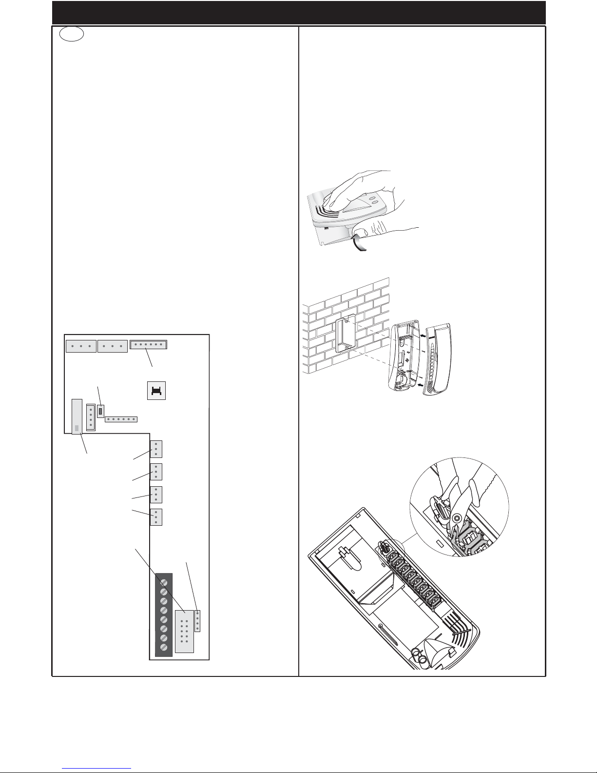
Fissare il citofono su
scatola rettangolare
verticale incassata per
mezzo delle 2 viti in
dotazione, oppure fissare le viti con i tasselli
ad espansione ø5 mm.
Collegare i fili ai morsetti. Si consiglia di fissare la parte superiore
del citofono ad un’altezza di m. 1,5 circa dal
pavimento.
Aggiunta pulsanti supplementari
L’aggiunta di pulsanti supplementari art. 692P, 692P/M per chiamate
intercomunicanti o servizi ausiliari prevede che i tasti del citofono in corrispondenza dei pulsanti aggiunti vengano liberati, tagliando il fermo in
plastica come indicato in figura 4.
Fig. 1
Fig. 2
Fig. 3
Fig. 4
Per separare il fondo
del citofono dal coperchio, fare forza nel lato
inferiore del citofono tra
il fondo e il coperchio
fino ad ottenere lo scatto di apertura.
I
Page 3

3
Fig. 7
A
C
B
PROGRAMMAZIONE
Le programmazioni del citofono sono di tre tipi: assegnazione codice
identificativo o codice di chiamata (indispensabile), assegnazione codice identificativo secondario (per citofoni associati ad un citofono di capo
gruppo), programmazione pulsanti per servizi ausiliari e chiamate intercomunicanti (dove necessario).
Le programmazioni devono essere effettuate con l’impianto acceso,
senza comunicazioni attive e solamente dopo aver collegato i
citofoni/videocitofoni all’impianto e programmato le targhe.
Programmazione codice identificativo
Il codice identificativo va programmato per mezzo di una targa (principale-MASTER), presente nell’impianto e già configurata.
Il citofono viene fornito senza codice identificativo assocciato. Per verificare ciò premere il pulsante serratura e il citofono emetterà un triplo
“Bip”.
Fase di programmazione:
1) Togliere il coperchio del citofono.
2) Premere e mantenere premuto il pulsante RESET presente nel citofono.
3) Premere e mantenere premuto la lamella corrispondente al pulsante serratura assieme al pulsante RESET.
4) Rilasciare il pulsante RESET, continuando a tenere premuto il pulsante serratura.
5) Dopo 2 secondi il citofono emette un tono acuto e viene messo in
comunicazione con la targa. Se al citofono è collegato anche il
monitor, quest’ultimo viene acceso e connesso alla telecamera
della targa.
6) Rilasciare la lamella corrispondente alla serratura.
7) Nelle targhe a pulsanti premere il pulsante di chiamata corrispondente al citofono, invece nelle targhe alfanumeriche comporre il
codice di chiamata e premere il pulsante “ ”.
8) Se nell’impianto esiste già un citofono con lo stesso codice identificativo associato, la targa emette un segnale sonoro basso ed è
necessario ripetere l’operazione dal punto 2.
9) In caso contrario il codice viene associato al citofono e la comunicazione viene terminata.
Programmazione codice identificativo secondario
La programmazione del codice identificativo secondario è richiesto solamente quando si vuole far suonare contemporaneamente più di un citofono con lo stesso pulsante o codice di chiamata. I citofoni che devono
suonare contemporanemente vengono associati ad uno stesso gruppo.
Il citofono di “capogruppo” viene programmato per primo attraverso la
precedente procedura “programmazione codice identificativo”, invece i
citofoni aggiuntivi del gruppo vengono programmati con il codice identificativo secondario.
Il numero di citofoni che si possono associare ad uno stesso gruppo,
senza l’ausilio del programmatore art. 950C, sono 4.
Nel caso che ai citofoni siano abbinati i monitor Petrarca, è necessario aggiungere un alimentatore supplementare art. 6923 per ogni
monitor aggiuntivo dopo il secondo monitor. Utilizzando il programmatore art. 950C, è possibile programmare l’attivazione della
suoneria di tutti i videocitofoni senza far accendere contemporaneamente tutti i monitor per poi accendere il monitor, dal citofono
da cui si risponde con il pulsante di autoaccensione; ciò permette
di non utilizzare alimentatori supplementari.
Fase di programmazione:
1) Togliere il coperchio del citofono.
2) Premere e mantenere premuto il pulsante RESET presente nel citofono.
3) Premere e mantenere premuti la lamella corrispondente al pulsante serratura e il pulsante di autoinserimento/autoaccensione (il 1°
pulsante sotto alla lamella), assieme al pulsante RESET.
4) Rilasciare il pulsante RESET, continuando a tenere premuti gli altri
2 pulsanti.
PROGRAMMAZIONE
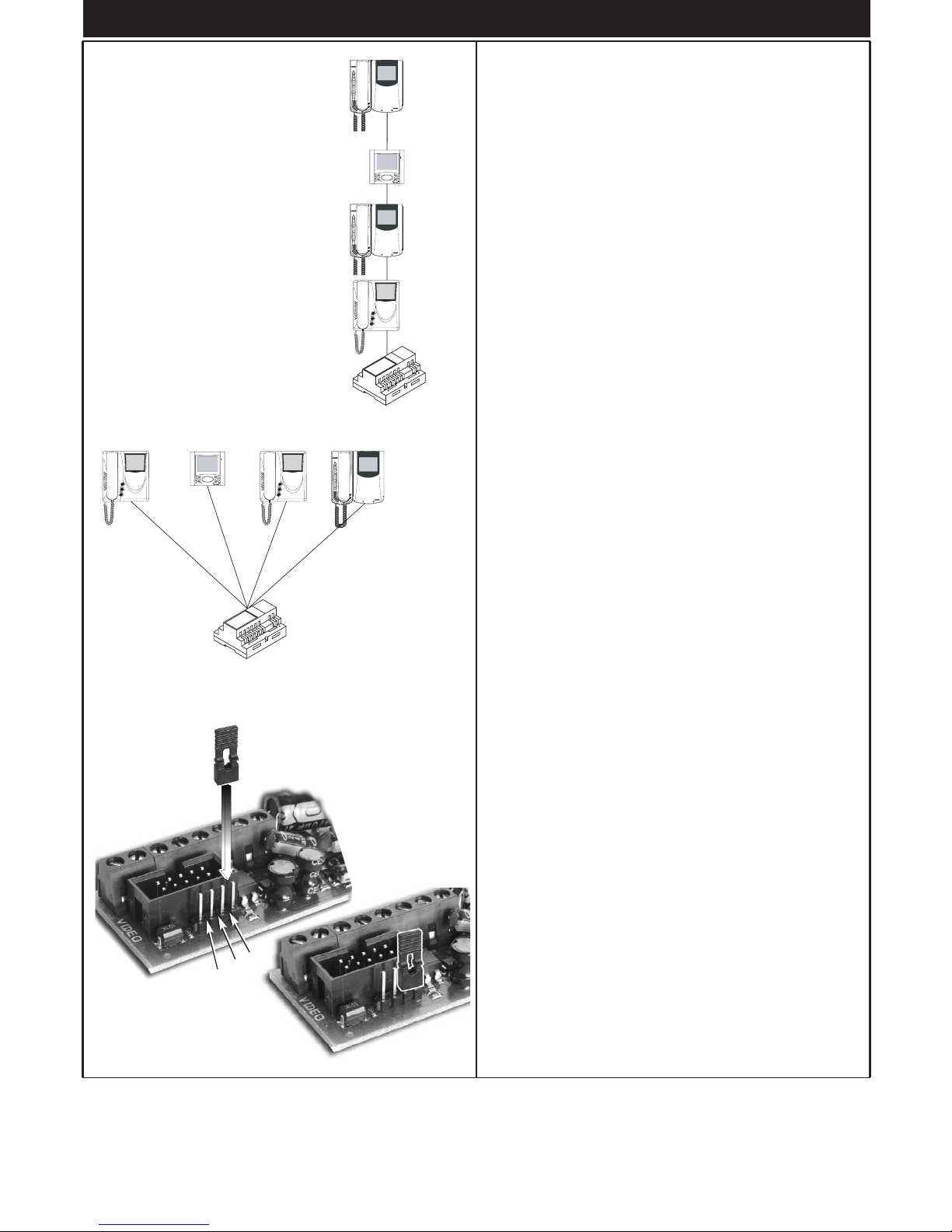
STABILIZZAZIONE SEGNALE VIDEO
Sul retro del citofono è presente un connettore
(A-B-C) ed un ponticello per la stabilizzazione
del segnale video, questo ponticello deve
essere utilizzato negli impianti dove sono presenti più apparecchi (citofoni o videocitofoni)
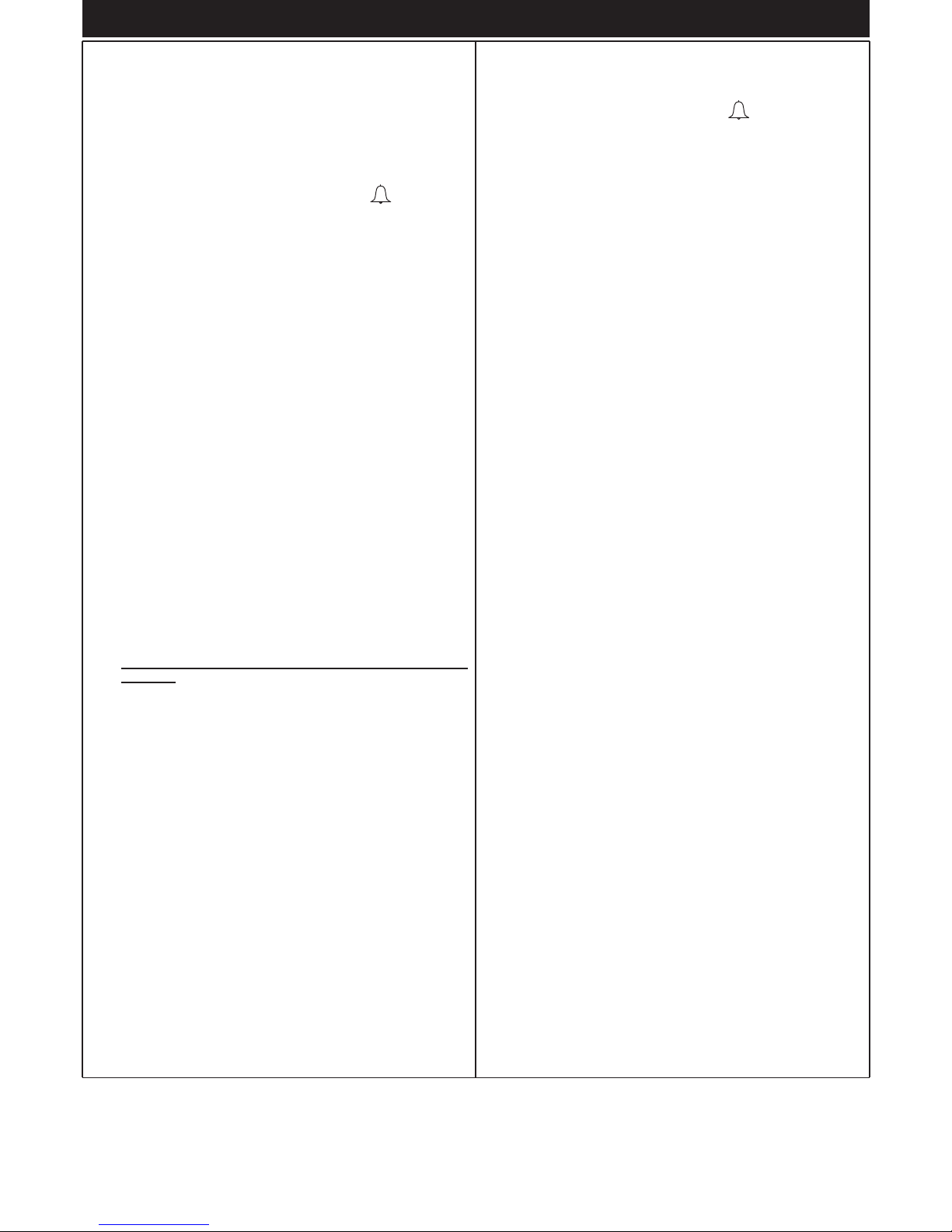
collegati in serie (fig. 5) o a stella (fig. 6).
In configurazione serie, spostare il ponticello
solo dell'ultimo apparecchio nella posizione
“Terminazione 100 Ohm” e mantenere i ponticelli degli altri nella posizione iniziale “Nessuna
terminazione” (Fig. 5).
Negli impianti con più
apparecchi (citofoni o
videocitofoni) collegati a stella, spostare in tutti gli
apparecchi il ponticello nella
posizione “Terminazione 100
Ohm” (Fig. 6).
Nel caso in cui l'immagine rappresentata nel videocitofono sia distorta,
spostare il ponticello in una delle posizioni alternative a quella iniziale
(100 Ohm o 50 Ohm), in modo da annullare la distorsione.
Fig. 5
100 Ohm 100 Ohm 100 Ohm 100 Ohm
Fig. 6
100 Ohm
Nessuna
Nessuna
Nessuna
Page 4
4
5) Dopo 2 secondi il citofono emette un tono acuto e viene messo in
comunicazione con la targa. Se al citofono è collegato anche il
monitor, quest’ultimo viene acceso e connesso alla telecamera
della targa.
6) Rilasciare la lamella corrispondente alla serratura e il pulsante di
autoinserimento/autoaccensione.
7) Nelle targhe a pulsanti premere il pulsante di chiamata corrispondente al citofono di “capogruppo” (già programmato), invece nelle
targhe alfanumeriche comporre lo stesso codice di chiamata del
citofono di “capogruppo” e premere il pulsante “ ”.
8) Associato l’identificativo secondario al citofono, la comunicazione
viene terminata.
Programmazione pulsanti
Il citofono viene fornito con una coppia di pulsanti aggiuntivi art. 692P,
per le funzioni di autoinserimento/autoaccensione e per il servizio ausiliario “luce scale”, il quale attiva il 1° relè del 1° attuatore (art. 692R), se
collegato all’impianto. È possibile inserire nel citofono altre 3 coppie di
pulsanti art. 692P, da collegare ai connettori T2-T3-T4, ai quali corrispondo le seguenti funzioni di default.
Pulsante Connettore Funzione di default
1° T1 Autoinserimento/autoaccensione
2° T1 Luce scale (1° relè del 1° attuatore, art.
692R)
3° T2 Ausiliario (2° relè del 1° attuatore, art.
692R)
4° T2 Non associato
5° T3 Non associato
6° T3 Non associato
7° T4 Funzione F1 della targa
8° T4 Funzione F2 della targa
Per cambiare il tipo di funzionamento degli 8 pulsanti è necessario utilizzare il programmatore art. 950C, ad eccezione per la programmazione
dei pulsanti intercomunicanti e il pulsante per il servizio di autoaccensione verso una targa specifica. Se un pulsante è programmato ad una
determinata funzione, il citofono emette un “Click” quando viene premuto, altrimenti non emette nessun segnale.
Programmazione pulsanti per chiamate intercomunicanti
Fase di programmazione:
1) Sganciare il microtelefono del citofono o videocitofono da
chiamare.
2) Togliere il coperchio del citofono da programmare.
3) Premere e mantenere premuto il pulsante RESET presente nel citofono.
4) Premere e mantenere premuto il pulsante supplementare per eseguire la chiamata intercomunicante assieme al pulsante RESET.
5) Rilasciare il pulsante RESET, continuando a tenere premuto il pulsante di chiamata.
6) Dopo 2 secondi il citofono emette un tono acuto, mentre l’altro citofono emette una scala tritonale ascendente.
7) Rilasciare il pulsante relativo alla chiamata intercomunicante.
8) Premere nel citofono chiamato (quello con il suono tritonale), uno
dei pulsanti programmati (come serratura o F1 o F2).
9) Un tono acuto conferma la fine della procedura.
Ripetere la stessa procedura anche per gli altri citofoni ed eventuali pulsanti di chiamata intercomunicante.
Programmazione pulsante autoaccensione verso targa specifica.
Fase di programmazione:
1) Togliere il coperchio del citofono.
2) Premere e mantenere premuto il pulsante RESET presente nel citofono.
3) Premere e mantenere premuto il pulsante supplementare per eseguire l’autoaccensione assieme al pulsante RESET
4) Rilasciare il pulsante RESET, continuando a tenere premuto il pulsante autoaccensione.
5) Dopo 2 secondi il citofono emette un tono acuto.
6) Rilasciare il pulsante relativo all’autoaccensione.
7) Nelle targhe a pulsanti premere il pulsante di chiamata corrispondente al citofono, invece nelle targhe alfanumeriche comporre il
codice di chiamata e premere il pulsante “ ”.
8) Un tono acuto conferma la fine della procedura.
Riprogrammazione valore di default dei pulsanti.
Fase di programmazione:
1) Togliere il coperchio del citofono.
2)
Premere e mantenere premuto il pulsante RESET presente nel citofono.
3) Premere e mantenere premuto il pulsante interessato da riprogrammare assieme al pulsante RESET.
4) Rilasciare il pulsante RESET, continuando a tenere premuto l’altro
pulsante.
5) Dopo 2 secondi il citofono emette un tono acuto.
6) Rilasciare il pulsante da riportare a default e ripremerlo.
Cancellazione totale delle programmazioni.
Fase di programmazione:
1) Togliere il coperchio del citofono.
2)
Premere e mantenere premuto il pulsante RESET presente nel citofono.
3) Premere e mantenere premuto il pulsante di autoaccensione assieme
al pulsante RESET.
4) Rilasciare il pulsante RESET, continuando a tenere premuto il pulsan-
te autoaccensione.
5) Dopo 2 secondi il citofono emette, per 2 secondi, un tono lungo.
6) Rilasciare il pulsante autoaccensione.
7) Durante il tono lungo, premere la lamella del pulsante serratura.
Se la procedura di cancellazione è andata a buon fine, premendo la
lamella della serratura il citofono emetterà un triplo “Bip”.
FUNZIONAMENTO
Le chiamate da targa esterna, intercomunicante e fuoriporta sono differenziate tra loro da toni diversi.
Chiamata da targa.
Le chiamate da targa non seguono la pressione del pulsante di chiamata ma vengono generate internamente dal citofono. Il periodo di chiamata è 1 secondo di suono e 2 secondi di pausa ripetuto per 2 volte (valore di default impostato nella targa). Per rispondere, sollevare il microtelefono. Se il microtelefono è già sollevato durante la chiamata riagganciare e risollevarlo. Il tempo di risposta alla chiamata (30 s) e il tempo di
conversazione (2 minuti di default) sono impostati nei parametri della
targa. Scaduto il tempo di conversazione, si può continuare, senza riagganciare il microtelefono, se viene eseguita di nuovo la chiamata entro
10 secondi dalla stessa targa.
Chiamata intercomunicante.
Sollevare il microtelefono del citofono, premere il pulsante intercomunicante relativo al citofono/videocitofono da chiamare. Nel microtelefono
del citofono chiamante si udrà un tono di chiamata (se la chiamata è
possibile) o tono di occupato (se la chiamata non è possibile). Nel citofono chiamato la suoneria inizierà a suonare ciclicamente con un ritmo
di 1 secondo di suono e 4 secondi di pausa. La durata massima della
chiamata sarà di 30 secondi (6 cicli). Per rispondere alla chiamata è sufficiente sollevare il microtelefono; la durata massima della conversazione è di 5 minuti. Scaduto il tempo di conversazione si può continuare la
conversazione, senza riagganciare il microtelefono, se viene eseguita di
nuovo la chiamata entro 10 secondi. Un’eventuale chiamata da targa ha
priorità su quella intercomunicante.
Chiamate rifiutate.
L’installazione dell’art. 6153/682 nel citofono, permette di variare l’intensità di chiamata o di escludere il suono di chiamata. L’esclusione della
chiamata è indicata dall’accensione permanente del LED rosso. Se vengono eseguite delle chiamate verso il citofono quando è in condizione di
chiamata esclusa, queste vengono rifiutate. Il rifiuto delle chiamate
determina un breve spegnimento del LED rosso tante volte sono le chiamate escluse (massimo chiamate escluse 4). La segnalazione viene
ripetuta ogni 10 secondi circa. La cancellazione delle chiamate rifiutate
avviene con: la riabilitazione della suoneria, con il reset del citofono o
l’assenza di alimentazione nell’impianto. Nelle targa il rifiuto è segnalato
con il tono dissuasione (una serie di “Bip” di 100ms con pausa di 100ms
per 5 secondi totali). Nella targa con display viene anche visualizzato il
messaggio “Non disturbare”.
PROGRAMMAZIONE/FUNZIONAMENTO
Page 5

5
INTRODUCTION/INSTALLATION
DESCRIPTION
Type 6209 is an interphone in the Petrarca series for ELVOX 2-WIRE
audio and video door entry systems. It is supplied as standard with 3
pushbuttons, one for lock release, one for self-start of the interphone in
the system even when not called, and one for the auxiliary “stair light”
service. The interphone can be fitted with an additional 3 pairs of
pushbutton types 692P (or 692P/M), for auxiliary services or intercommunicating calls, and the accessory type 6153/682 for: call volume adjustment, call signal mute, call denied luminous indicators, signal to indicate unanswered calls, signal to indicate services not available and luminous signal for gate/door open. The interphone can be installed as a
wall-mounted version or desktop using the conversion kit type 6140 or
6A40, or in combination with monitors in the Petrarca series type 6009
(b/w monitor) or type 6009/C (colour monitor) by means of wall bracket
type 6145 or desktop conversion kit type 6142 or 6A42.
Connection and connector terminal board
1, 2) BUS line.
4, 6P) Connection for door call pushbutton.
5, 6S) Connection of additional door ringtone
-, +)
Additional power supply for monitor with power supply type 6923.
VARIAT.) Connection for module type 6153/682.
VIDEO) Connection for monitor type 6009 or 6009/C.
T1) 1st pair of pushbuttons type 692P.
T2) 2nd pair of pushbuttons type 692P.
T3) 3rd pair of pushbuttons type 692P.
T4) 4th pair of pushbuttons type 692P.
Controls
The call volume can be adjusted by moving the loudspeaker wire from
connector A+ (high) to A- (low); otherwise use accessory type 6153/682,
leaving the loudspeaker wire connected to connector A-.
INSTALLATION
Wall-mounted installations of the interphone do not require additional
accessories. However a vertical 3-module box may be used to facilitate
fixture and cable routing. For desktop installations and combinations with
monitors, refer to the respective instructions of the conversion kit or
monitor.
Surface wall-mounted intallation
BL BIRO A+ CAA- VAR IAT.
SERR.
SERIALE
RESET
PRG.
T1
T2
T3
T4
VIDEO
1
1
2
4
5
6S
6P
-
+
T1
T2
T3
T4
Per art. 6153/682
RESET
SERRATURA
Per art. 6009 o
6009/C
Stabilizzazione
segnale video
Fix the interphone to
the rectangular, vertical
flush-mounted backbox with the 2 screws
supplied, or fix the
screws with the ø5
expansion plugs.
Connect the wires to
the terminals. You are
advised to fix the top of
the interphone at a
height of about 1.5 m
above the ground.
Fitting additional pushbuttons
The insertion of additional pushbuttons type 692P, 692P/M for intercommunicating calls or auxiliary services requires release of the interphone
keys in the location of the additional pushbuttons, by cutting the plastic
retainer as shown in figure 4.
Fig. 1
Fig. 2
Fig. 3
Fig. 4
Video signal
stabiliser
To split the interphone
bottom from the cover,
force on the interphone
lower side between the
bottom and the cover
until the snapping click.
GB
Page 6
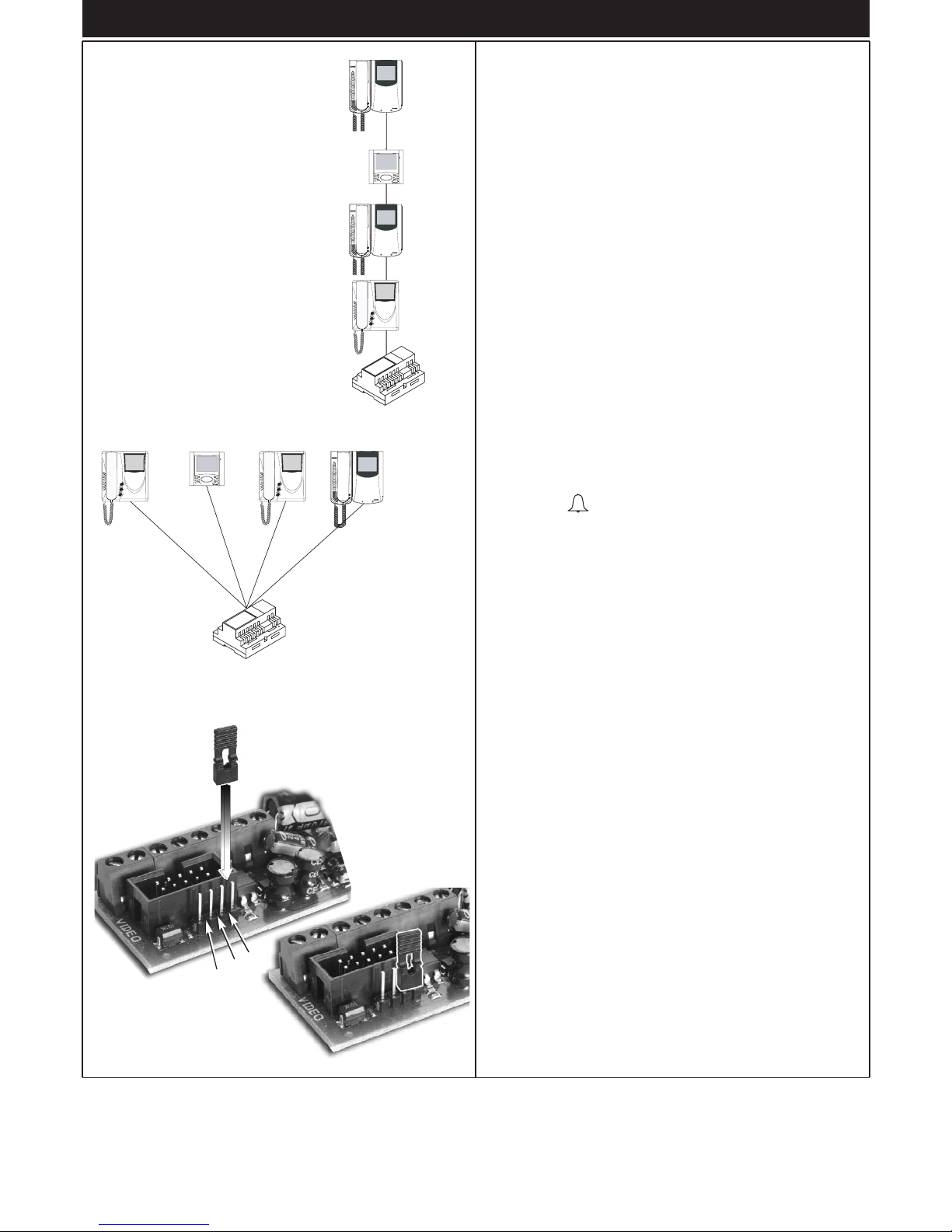
Fig. 7
A
C
B
PROGRAMMING
There are three interphone programming modes: assignment of an identification code or call code (indispensable), assignment of a secondary
identification code (for interphones associated with a master interphone), programming of pushbuttons for auxiliary services and intercommunicating calls (when necessary).
Programming must be performed with the system switched on, without
active communication and only after connecting the interphones/monitors to the system and programming the panels.
Identification code programming
The identification code is programmed via an entrance panel (MASTER),
already configured and present on the system.
The interphone is supplied without associated identification code. To
verify this condition, press the lock release pushbutton and the interphone should emit a triple “Beep”.
Programming phase:
1) Remove the interphone cover.
2) Press and hold the RESET pushbutton on the interphone.
3) Press and hold the tab on the lock release pushbutton, together with
the RESET pushbutton.
4) Release the RESET pushbutton, keeping the lock release pushbut-
ton pressed.
5) After 2 seconds the interphone emits a high tone and communication
is enabled with the panel. If the monitor is also connected to the interphone, it is switched on and connected to the camera of the entrance panel.
6) Release the tab of the lock release pushbutton.
7) On pushbutton entrance panels, press the call button for the inter-
phone, while on alphanumeric keypads, enter the call code and press
pushbutton “ ”.
8) If the system contains an interphone that already has the same asso-
ciated identification code, the panel emits a low signal and the operation should be repeated from point 2.
9) Otherwise the code is associated with the interphone and communi-
cation is terminated.
Secondary identification code programming
Programming of the secondary identification code is only required when
more than one interphone is to be called by means of the same pushbutton or call code. The interphones that ring at the same time are associated with the same group. The “master” interphone is programmed first by
means of the “identification code programming” procedure described
above, while the additional group interphones are programmed with the
secondary identification code.
A maximum of four interphones can be associated with the same group,
without the need for programmer type 950C.
If the interphones are combined with Petrarca monitors, an additional power supply type 6923 must be fitted for each additional monitor after the second monitor. Using programmer type 950C, activation of the ringtone on all monitors can be programmed, without
simultaneous activation of all monitors, to then enable activation of
the monitor from the interphone used to answer the call with the
self-start pushbutton; this avoids the need to use additional power
supplies.
Programming phase:
1) Remove the interphone cover.
2) Press and hold the RESET pushbutton on the interphone.
3) Press and hold the tab on the lock release pushbutton and the self
start/auto-activation pushbutton (the first pushbutton below the tab),
together with the RESET pushbutton.
4) Release the RESET pushbutton, keeping the other two pushbuttons
pressed.
PROGRAMMING
6
VIDEO SIGNAL STABILISATOR
On the rear of the interphone there is a connector (A-B-C) and a jumper for the video
signal balance. This jumper must be used on
the installations where there are more appliances (interphones or monitors) connected in
series (Fig. 5) or with star connection (Fig. 6).
On the standard configuration displace the
jumper into "Terminazione 100 Ohm"
(Termination 100 Ohm) only on the last set and
keep the jumpers on the other appliances in
the initial position "Nessuna terminazione" (No
termination" (Fig. 5).
On installations with several
appliances (interphones or
monitors) with star connection, displace the jumper
into "Terminazione 100
Ohm" (Termination 100
Ohm) in all appliances.
If the image shown on the monitor is distorted, displace the jumper into
one of the alternative positions to the initial one (100 Ohm or 50 Ohm),
so as to eliminate the distortion.
Fig. 5
100 Ohm 100 Ohm 100 Ohm 100 Ohm
Fig. 6
100 Ohm
Nothing
Nothing
Nothing
Page 7
7
5) After 2 seconds the interphone emits a high tone and communication is enabled with the panel. If the monitor is also connected to the
interphone, it is switched on and connected to the camera of the
entrance panel.
6) Release the tab on the lock release pushbutton and the self start
pushbutton.
7) On pushbutton entrance panels, press the call button for the
“master” interphone (already programmed), while on alphanumeric
keypads, enter the call code of the “master” interphone and press
pushbutton “ ”.
8) When the secondary code is associated with the interphone and
communication is terminated.
Pushbutton programming
The interphone is supplied with a pair of additional pushbuttons type
692P, for the functions self start and the auxiliary service “stair light”,
which activates the 1st relay of the 1st actuator (type 692R), if connected to the system. A further three pairs of pushbuttons type 692P can be
inserted in the interphone, to be connected to connectors T2-T3-T4, corresponding to the following default functions.
Pushbutton Connector Default function
1 T1 Self-start
2 T1 Stair light (1st relay of 1st actuator,
type 692R)
3 T2 Auxiliary (2nd relay of 1st actuator,
type 692R)
4° T2 Not associated
5° T3 Not associated
6° T3 Not associated
7° T4 Function F1 on panel
8° T4 Function F2 on panel
To change the operating mode of the 8 pushbuttons, use programmer
type 950C, with the exception of programming intercommunicating
pushbuttons and the pushbutton for the self-start service associated with
a specific panel.
If a pushbutton is programmed for a specific function, the interphone
emits a “Click” when pressed; otherwise it does not emit any signal.
Intercommunicating call pushbutton programming
Programming phase:
1) Raise
the handset of the interphone or monitor to be called.
2) Remove the cover of the interphone to be programmed.
3) Press and hold the RESET pushbutton on the interphone.
4) Press and hold the additional pushbutton to make the intercommuni-
cating call together with the RESET pushbutton.
5) Release the RESET pushbutton, keeping the call pushbutton pres-
sed.
6) After 2 seconds the interphone emits a high tone, while the other
interphone emits a 3-tone ascending scale.
7) Release the intercommunicating call pushbutton.
8) On the interphone called (with the 3-tone ring), press one of the pro-
grammed pushbuttons (such as lock release, F1 or F2).
9) A high tone confirms the end of the procedure.
Repeat the same procedure for the other interphones and any other
intercommunicating call pushbuttons.
Programming the self-start pushbutton to a specific panel.
Programming phase:
1) Remove the interphone cover.
2) Press and hold the RESET pushbutton on the interphone.
3) Press and hold the additional pushbutton to activate the self-start
function together with the RESET pushbutton.
4) Release the RESET pushbutton, keeping the self-start pushbutton
pressed.
5) After 2 seconds the interphone emits a high tone.
6) Release the self-start pushbutton.
7) On pushbutton entrance panels, press the call button for the interphone, while on alphanumeric keypads, enter the call code and
press pushbutton “ ”.
8) A high tone confirms the end of the procedure.
Restoring default values of pushbuttons.
Programming phase:
1) Remove the interphone cover.
2) Press and hold the RESET pushbutton on the interphone.
3) Press and hold the relative pushbutton to be reprogrammed together
with the RESET pushbutton.
4) Release the RESET pushbutton, keeping the other pushbutton pressed.
5) After 2 seconds the interphone emits a high tone.
6) Release the pushbutton to restore to default and then press again.
Deleting all settings.
Programming phase:
1) Remove the interphone cover.
2) Press and hold the RESET pushbutton on the interphone.
3) Press and hold the self start pushbutton together with the RESET
pushbutton.
4) Release the RESET pushbutton, keeping the self-start pushbutton
pressed.
5) After 2 seconds the interphone emits a continuous tone for two
seconds.
6) Release the self-start pushbutton.
7) During the continuous tone, press the tab on the lock release
pushbutton.
If the deletion procedure is successful, when the lock release tab is pressed the interphone emits a triple “Beep”.
OPERATION
Calls from an entrance panel, intercommunicating calls and door calls
are differentiated by means of different tones.
Door calls.
Calls from entrance panels do not follow the pressed pushbutton but are
generated inside the interphone. The call interval is 1 second of ringtone and 2 seconds of pause repeated twice (default value set on panel).
To answer, raise the handset. If the handset is already raised during the
call, replace and raise it again. The call answer time (30 s) and the conversation time (2 minutes by default) are set in the panel parameters.
When the conversation time has elapsed, the user can continue without
replacing the handset if a new call is made within 10 seconds from the
same panel.
Intercommunicating call.
Lift the handset and press the intercommunicating button for the interphone/monitor to be called. On the handset of the interphone called a
call tone will ring (if the call is enabled) or an engaged tone (if not enabled). On the called interphone the ringtone starts sequentially at intervals of 1 second ringing and 4 seconds pause. The maximum duration
of the call is 30 seconds (6 cycles). To answer the call, simply raise the
handset; the maximum duration of the conversation is 60 seconds.
When the conversation time has elapsed, the user can continue without
replacing the handset if a new call is made within 10 seconds. Calls from
the panel have priority over intercommunicating calls.
Denied calls.
Installation of type 6153/682 in the interphone, enables the user to vary
the call intensity or mute the ringtone. Call mute is indicated by permanent illumination of the red LED. If calls are made to the interphone when
the call mute is enabled, they are denied. A denied call causes the red
Led to briefly switch off according to the number of times calls are denied
(maximum 4 denied calls). The signal is repeated every 10 seconds
(approx.). Deletion of denied calls is by: reenabling the ringtone, resetting the interphone or a system power failure. On the panel, a denied call
is indicated by means of a dissuasion tone (a series of “Beeps” at 100ms
intervals with a pause of 100ms for a total of 5 seconds).
The message “Do not disturb” also appears on panels with display.
PROGRAMMING/OPERATING
Page 8
8
INTRODUCTION/INSTALLATION
DESCRIPTION
L'art. 6209 est un portier audio de la série Petrarca pour systèmes de
portiers audio ou vidéo 2 FILS ELVOX. Livré avec 3 boutons de série :
un pour la commande de la gâche, un pour l'allumage/extinction automatique du poste même sans appel et un pour le service auxiliaire
d'éclairage escalier. Le portier audio peut recevoir 3 autres paires de
boutons art. 692P (ou 692P/M) pour les services auxiliaires ou la communication entre postes et l'accessoire art. 6153/682 pour : réglage du
volume d'appel, exclusion du signal d'appel, signalisation lumineuse
d'appel exclu, signalisation d'appel sans réponse et signalisation de services non disponibles et signalisation lumineuse de porte ouverte/portail
ouvert. L'installation du portier audio est réalisable en version murale ou
en version de table à l'aide des kits de transformation art. 6140 ou 6A40
ou bien en combinaison avec les moniteurs de la série Petrarca art.
6009 (moniteur N/B) ou art. 6009/C (moniteur couleur) à l'aide de la
patte de support mural art. 6145 ou du kit de transformation version de
table art. 6142 ou 6A42.
Bornier de connexion et connecteurs
1, 2) Ligne BUS.
4, 6P) Raccordement pour bouton-poussoir d'appel de palier
5, 6S) Raccordement sonnerie supplémentaire.
-, +) Alimentation supplémentaire pour moniteurs art. 6923.
VARIAT.) Raccordement pour module art. 6153/682.
VIDEO) Raccordement pour moniteur art. 6009 ou 6009/C.
T1) 1ère paire de boutons art. 692P.
T2) 2ème paire de boutons art. 692P.
T3) 3ème paire de boutons art. 692P.
T4) 4ème paire de boutons art. 692P.
Réglages
Le volume d'appel est réglable en déplaçant le fil du haut-parleur entre
le connecteur A+ (ton haut) et A- (ton bas), sinon utiliser l'accessoire art.
6153/682 en laissant le fil du haut-parleur relié au connecteur A-.
INSTALLATION
L'installation en saillie du portier audio ne nécessite pas d'accessoires
supplémentaires. Toutefois, il est possible de prévoir une boîte 3 modules verticale pour faciliter la fixation et le passage du câblage. Pour l'installation de la version de table en combinaison avec le moniteur, voir
respectivement les instructions des kits de transformation et des moniteurs.
Installation murale en saillie
BL BIRO A+ CAA- VAR IAT.
SERR.
SERIALE
RESET
PRG.
T1
T2
T3
T4
VIDEO
1
1
2
4
5
6S
6P
-
+
T1
T2
T3
T4
Per art. 6153/682
RESET
SERRATURA
Per art. 6009 o
6009/C
Stabilizzazione
segnale video
Fixer le portier sur un
boîtier rectangulaire
vertical encastré avec
les 2 vis livrées en standard ou fixer ces vis sur
des chevilles à expansion ø5. Effectuer les
raccordements aux bornes. On conseille de
murer le côté supérieur
à environ 1,5 m du niveau du sol.
Adjonction de boutons supplémentaires
L'adjonction de boutons supplémentaires art. 692P, 692P/M pour communication entre postes ou services auxiliaires prévoit que les touches
du portier audio destinées à recevoir les boutons supplémentaires doivent être libérées en coupant l'arrêt plastique comme le montre la figure
4.
Fig. 1
Fig. 2
Fig. 3
Fig. 4
Pour séparer le fond du
poste d'appartement du
couvercle, faire force
sur le côté inférieur du
poste entre le fond et le
couvercle jusqu'à obtenir le click d'ouverture.
Stabilisateur de
signal vidéo
F
Page 9
9
Fig. 7
A
C
B
PROGRAMMATION
Les programmations du portier audio sont de trois types : assignation
d'un code d'identification ou d'un code d'appel (indispensable), assignation d'un code d'identification secondaire (pour portiers audio associés à
un portier audio "Master"), programmation des boutons pour services
auxiliaires et la communication entre postes (lorsque cela est nécessaire).
Les programmations doivent être effectuées avec le système allumé,
sans communication en cours et seulement après avoir relié les portiers
audio et/ou vidéo au système et programmé les plaques de rue.
Programmation du code d'identification
Le code d'identification doit être programmé par l'intermédiaire d'une
plaque de rue (principale-"MASTER"), montée dans le système et déjà
configurée.
Le portier audio est fourni sans code d'identification associé. Pour vérifier cette condition, appuyer sur le bouton de commande de la gâche. Le
portier audio émettra un triple “Beep”.
Étapes de la programmation:
1) Déposer la face avant du portier audio.
2) Appuyer et garder le doigt sur le bouton RESET du portier audio.
3) Appuyer et garder le doigt sur la lamelle correspondant au bouton de
commande de la gâche, en même temps que le bouton RESET.
4) Relâcher le bouton RESET tout en continuant à maintenir enfoncé le
bouton de commande de la gâche.
5) Après 2 secondes, le portier émet une tonalité aiguë et est mis en
communication avec la plaque de rue. Si le moniteur est également
relié au portier audio, celui-ci s'allume pour être connecté à la caméra de la plaque de rue.
6) Relâcher la lamelle correspondant à la gâche.
7) Appuyer sur le bouton d'appel correspondant au portier audio sur les
plaques de rue à boutons. Taper le code d'appel et appuyer sur le
bouton II sur les plaques de rue alphanumériques.
8) Si le système comprend déjà un portier audio avec le même code
d'identification associé, la plaque de rue émet un signal sonore faible et il faut nécessairement reprendre l'opération du point 2.
9) Dans le cas contraire, le code est associé au portier audio et la communication est coupée.
Programmation du code d'identification secondaire
La programmation du code d'identification secondaire n'est requise que
pour faire sonner simultanément plus d'un portier audio avec le même
bouton ou code d'appel. Les portiers audio qui doivent sonner simultanément sont associés à un même groupe. Le portier audio "Master" est
programmé en premier en utilisant la procédure précédente de “programmation du code d'identification”, tandis que les portiers audio supplémentaires du groupe sont programmés avec le code d'identification
secondaire.
Le portier audio pouvant être associé à un même groupe, sans l'aide du
programmateur art. 950C, sont au nombre de 4.
Dans le cas de combinaison des portiers audio avec les moniteurs
Petrarca, il faut nécessairement ajouter une alimentation supplémentaire art. 6923 pour chaque moniteur en plus du deuxième
moniteur. Avec le programmateur art. 950C, il est possible de programmer l'activation de la sonnerie de tous les portiers vidéo sans
allumer simultanément tous les moniteurs, pour allumer ensuite le
moniteur du portier audio appelé avec le bouton d'auto-allumage.
Cette solution permet ainsi de ne pas utiliser d'alimentations supplémentaires.
Étapes de la programmation :
1) Déposer la face avant du portier audio.
2) Appuyer et garder le doigt sur le bouton RESET du portier audio.
3) Appuyer et garder le doigt sur la lamelle correspondant au bouton de
la gâche et sur le bouton auto-enclenchement/auto-allumage (le 1er
bouton sous la lamelle), en même temps que le bouton RESET.
4) Relâcher le bouton RESET tout en maintenant enfoncés les deux
autres boutons.
PROGRAMMATION
STABILISATEUR DU SIGNAL VIDÉO
Derrière du poste d'appartement il y a un connecteur (A-B-C) et un pontage pour la stabilisation du signal vidéo. Ce pontage doit être utilisé dans les installation avec plusieurs appareils (postes d'appartement ou moniteurs) raccordés en série (Fig. 5) ou à étoile (Fig. 6).
Dans la configuration de série déplacer le pontage sur la position «Terminazione 100 Ohm»
(termination 100 Ohm) seulement dans le dernier appareil et maintenir les pontages des
autres appareils sur la position initiale
«Nessuna Terminazione» (Aucune
Termination).
Dans les installations avec
plusieurs appareils (postes
d'appartement ou moniteurs) connectés à étoile,
déplacer le pontage sur la
position «Terminazione
100 Ohm» (Termination
100 Ohm) (Fig. 8) dans
tous les appareils.
Si l'image dans le moniteur est déformé, déplacer le pontage sur une
des positions alternatives a celle initiale (100 Ohm ou 50 Ohm), de façon
a annuler la déformation.
Fig. 5
100 Ohm 100 Ohm 100 Ohm 100 Ohm
Fig. 6
100 Ohm
Nessuna
Nessuna
Nessuna
Page 10

1010
5) Après 2 secondes, le portier audio émet une tonalité aiguë et est mis
en communication avec la plaque de rue. Si le moniteur est également relié au portier audio, celui-ci s'allume pour être connecté à la
caméra de la plaque de rue.
6) Relâcher la lamelle correspondant à la gâche et le bouton d'autoenclenchement/auto-allumage.
7) Appuyer sur le bouton d'appel correspondant au portier audio
"Master" (déjà programmé) sur les plaques de rue à boutons. Taper
le même code d'appel du portier audio "Master" et appuyer sur le
bouton “ ” sur les plaques de rue alphanumériques.
8) Une fois l'identificateur secondaire associé au portier audio, la communication est coupée.
Programmation des boutons
Le portier est fourni avec une paire de boutons supplémentaires art.
692P pour les fonctions d'auto-enclenchement/auto-allumage et pour le
service auxiliaire d'éclairage escalier, lequel active le 1er relais du 1er
actionneur (art. 692R), si connecté au système. Il est possible en outre
de prévoir trois autres paires de boutons art. 692P à relier aux connecteurs T2-T3-T4, auxquels sont associées les fonctions par défaut ciaprès.
Bouton Connecteur Fonction par défaut
1er T1 Auto-enclenchement/auto-allumage
2ème T1 Éclairage escalier (1er relais du 1er
actionneur, art. 692R)
3ème T2 Auxiliaire (2ème relais du 1er actionneur,
art. 692R)
4ème T2 Non associé
5ème T3 Non associé
6ème T3 Non associé
7ème T4 Fonction F1 de la plaque de rue
8ème T4 Fonction F2 de la plaque de rue
Pour changer le type de fonctionnement des 8 boutons, il est nécessaire d'utiliser le programmateur art. 950C, excepté pour la programmation
des boutons d'appel pour communication entre postes et le bouton pour
le service d'auto-allumage vers une plaque de rue spécifique.
Si un bouton est programmé pour une fonction donnée, le portier audio
émet un “clic” au moment de sa pression, sinon il reste muet.
Programmation des boutons pour communication entre postes
Étapes de la programmation:
1) Décrocher
le combiné du portier audio ou vidéo à appeler.
2) Déposer la face avant du portier audio à programmer.
3) Appuyer et garder le doigt sur le bouton RESET du portier audio.
4) Appuyer et garder le doigt sur le bouton de communication entre
postes supplémentaire, en même temps que le bouton RESET.
5) Relâcher le bouton RESET tout en continuant à maintenir enfoncé le
bouton d'appel.
6) Après 2 secondes, le portier audio émet une tonalité aiguë, tandis
que l'autre portier audio émet une échelle triton ascendante.
7) Relâcher le bouton de communication entre postes.
8) Appuyer sur un des boutons programmés (comme gâche ou F1 ou
F2) du portier audio appelé (celui qui émet le son triton).
9) Une tonalité aiguë confirme la fin de la procédure.
Répéter aussi la même procédure pour les autres portiers audio et éventuels boutons d'appel pour communication entre deux postes.
Programmation du bouton d'auto-allumage vers la plaque de rue
spécifique.
Étapes de la programmation:
1) Déposer la face avant du portier audio.
2) Appuyer et garder le doigt sur le bouton RESET du portier audio.
3) Appuyer et garder le doigt sur le bouton d'auto-allumage supplémen-
taire, en même temps que le bouton RESET
4) Relâcher le bouton RESET tout en continuant à maintenir enfoncé le
bouton d'auto-allumage.
5) Le portier audio émet une tonalité aiguë après 2 secondes.
6) Relâcher le bouton d'auto-allumage.
7) Appuyer sur le bouton d'appel correspondant au portier audio sur les
plaques de rue à boutons. Taper le code d'appel et appuyer sur le
bouton “ ” sur les plaques de rue alphanumériques.
8) Une tonalité aiguë confirme la fin de la procédure.
Reprogrammation de la valeur par défaut (autrement dit d'usine)
des boutons.
Étapes de la programmation:
1) Déposer la face avant du portier audio.
2) Appuyer et garder le doigt sur le bouton RESET du portier audio.
3) Appuyer et garder le doigt sur le bouton à reprogrammer, en même
temps que le bouton RESET.
4) Relâcher le bouton RESET tout en continuant à maintenir enfoncé
l'autre bouton.
5) Le portier audio émet une tonalité aiguë après 2 secondes.
6) Relâcher le bouton à reprogrammer à la valeur par défaut et appuyer
à nouveau sur celui-ci.
Effacement des programmations.
Étapes de la programmation:
1) Déposer la face avant du portier audio.
2) Appuyer et garder le doigt sur le bouton RESET du portier audio.
3) Appuyer et garder le doigt sur le bouton d'auto-allumage, en même
temps que le bouton RESET.
4) Relâcher le bouton RESET tout en continuant à maintenir enfoncé le
bouton d'auto-allumage.
5) Après 2 secondes, le portier audio émet une tonalité longue pendant
2 secondes.
6) Relâcher le bouton d'auto-allumage.
7) Pendant le retentissement de la tonalité longue, appuyer sur la lamelle du bouton de commande de la gâche.
Si la procédure d'effacement est réussie, le portier audio émettra un triple “Beep” en appuyant sur la lamelle de la gâche.
FONCTIONNEMENT
Les appels de palier, de la plaque de rue et pour communication entre
postes se distinguent par leur tonalité différente.
Appel de la plaque de rue.
Les appels de la plaque de rue ne répondent pas à la pression du bouton, mais sont générés à l'intérieur par le portier audio. La période d'appel est de 1 seconde de tonalité et de 2 secondes de pause, qui se répète deux fois (valeur par défaut définie dans la plaque de rue). Pour
répondre, décrocher le combiné. Si le combiné est déjà soulevé pendant
l'appel, le raccrocher puis le décrocher à nouveau. Le temps de réponse à l'appel (30 s) et la durée de conversation (2 minutes par défaut)
sont définies dans les paramètres de la plaque de rue. Une fois la durée
de conversation écoulée, il est possible de continuer à dialoguer, sans
raccrocher le combiné, si un autre appel est effectué depuis la même
plaque de rue dans les 10 secondes qui suivent.
Appel pour communication entre postes.
Décrocher le combiné du portier audio, appuyer sur le bouton de communication entre postes du portier audio ou vidéo à appeler. Le combiné du portier audio appelant émettra une tonalité d'appel (si l'appel est
possible) ou une tonalité occupé (si l'appel est impossible). La sonnerie
du portier appelé commencera à retentir par séquences répétitives de 1
seconde de tonalité et de 4 secondes de pause. La durée maximale de
l'appel sera de 30 secondes (6 séquences). Pour répondre à l'appel, il
suffit de soulever le combiné; la durée maximale de la conversation est
de 5 minutes. Une fois la durée de conversation écoulée, il est possible
de continuer à dialoguer, sans raccrocher le combiné, si un visiteur
appelle de nouveau dans les 10 secondes qui suivent. Un appel éventuel depuis la plaque de rue est prioritaire sur celui pour communication
entre postes.
Appels refusés.
Le montage de l'art. 6153/682 dans le portier permet de varier le volume
sonore de l'appel ou d'exclure la tonalité d'appel. L'exclusion de l'appel
est signalée par l'allumage (lumière fixe) de la LED rouge. Si des appels
sont effectués vers le portier audio lorsqu'il est en condition d'appel
exclu, ceux-ci sont refusés. Le refus des appels détermine une extinction de courte durée de la LED rouge pour chaque appel exclu (4 au
maximum). La signalisation est répétée environ toutes les 10 secondes.
L'effacement des appels refusés se produit : avec le rétablissement de
la sonnerie, avec la réinitialisation du portier audio ou à défaut d'alimentation du système. Le refus, sur la plaque de rue, est signalé par la tonalité de dissuasion (une série de “Beep” de 100 ms avec une pause de
100 ms pendant une durée totale de 5 secondes).Le message “Ne pas
déranger” apparaît en plus sur la plaque de rue avec moniteur.
PROGRAMMAZIONE/FUNZIONAMENTO
Page 11

11
EINFÜHRUNG/INSTALLATION
BESCHREIBUNG
Der Art. 6209 ist ein Haustelefon der Serie Petrarca für ZWEIDRAHTSprechanlagen und -Videosprechanlagen ELVOX, das serienmäßig mit
3 Tasten ausgestattet ist: einem Türöffner, einer Taste zur
Selbsteinschaltung des Haustelefons in der Anlage, auch wenn es nicht
angerufen wurde, und einer Taste für die Zusatzfunktion
“Treppenhausbeleuchtung”. Das Haustelefon kann um weitere 3
Tastenpaare Art. 692P (oder 692P/M) für Zusatzfunktionen oder interne
Rufe erweitert werden, sowie um das Zubehör Art.. 6153/682 für:
Ruflautstärkeregelung, Rufsignalabschaltung, Leuchtanzeige für
Rufabschaltung, Anzeige unbeantworteter Rufe, Anzeige nicht verfügbarer Funktionen und Leuchtanzeige für Tür/Tor offen.
Das Haustelefon kann in der Version für die Wandmontage installiert,
oder mit Hilfe der Umbausätze Art. 6140 oder 6A40 als Tischgerät aufgestellt werden. In Kombination mit den Monitoren der Serie Pertrarca
Art. 6009 (S/W-Monitor) oder Art. 6009/C (Farbmonitor) wird es mit dem
Haltebügel Art. 6145 an der Wand installiert, oder mit Hilfe der
Umbausätze Art. 6142 oder 6A42 als Tischgerät aufgestellt.
Anschlussklemmenleiste und Steckverbinder
1, 2) BUS-Leitung.
4, 6P) Anschluss für Etagenruftaste.
5, 6S) Anschluss Zusatzläutwerk.
-, +) Zusatzversorgung für Monitor mit Netzgerät Art. 6923.
VARIAT.) Anschluss für Modul Art. 6153/682.
VIDEO) Anschluss für Monitor Art. 6009 oder 6009/C.
T1) 1. Tastenpaar Art. 692P.
T2) 2. Tastenpaar Art. 692P.
T3) 3. Tastenpaar Art. 692P.
T4) 4. Tastenpaar Art. 692P.
Einstellungen
Die Ruflautstärke kann reguliert werden, indem der Draht des
Lautsprechers zwischen dem Steckverbinder A+ (lauter Ton) und A- (leiser Ton) verschoben wird, andernfalls das Zubehör Art. 6153/682 benutzen und den Draht des Lautsprechers am Steckverbinder A- angeschlossen lassen.
INSTALLATION
Für die Installation des Aufputz-Haustelefons ist kein zusätzliches
Zubehör erforderlich. Es kann jedoch ein senkrechtes 3-Modul-Gehäuse
verwendet werden, um die Befestigung und den Kabeldurchzug zu erleichtern. Für die Installation als Tischgerät und in Kombination mit dem
Monitor wird auf die Anleitungen der Umbausätze bzw. der Monitoren
verwiesen.
Ap-Montage
BL BIRO A+ CAA- VAR IAT.
SERR.
SERIALE
RESET
PRG.
T1
T2
T3
T4
VIDEO
1
1
2
4
5
6S
6P
-
+
T1
T2
T3
T4
Per art. 6153/682
RESET
SERRATURA
Per art. 6009 o
6009/C
Stabilizzazione
segnale video
Das Haustelefon mit
den zwei mitgelieferten
Schrauben am rechteckigen senkrechten UPGehäuse oder mit
Spreizdübeln ø5 befestigen. Die Leiter an die
Klemmenleiste
anschließen. Es wird
empfohlen, die obere
Kante des
Türsprechgeräts etwa
1,5 m über dem
Fußboden zu montieren.
Erweiterung um zusätzliche Tasten
Bei Erweiterung um zusätzliche Tasten Art. 692P, 692P/M für interne
Rufe oder Zusatzfunktionen müssen die Tasten des Haustelefons dort,
wo die Tasten hinzugefügt werden sollen, freigegeben werden. Dazu die
Plastiksperre wie auf Abbildung 4 durchschneiden.
Um den Haustelefonsboden
vom Deckel zu trennen,
Macht anwenden an die
Unterseite des Haustelefons
zwischen dem Boden und
dem Deckel bis es hörtbar
geöffnet.
Fig. 1
Fig. 2
Fig. 3
Fig. 4
Stabilisator des
Videosignals
D
Page 12

12
Fig. 7
A
C
B
PROGRAMMIERUNG
Es gibt drei Programmierungsarten des Haustelefons: Zuweisung des
Kenncodes oder Rufcodes (unbedingt notwendig), Zuweisung des
zusätzlichen Kenncodes (für Haustelefone, die mit einem HauptHaustelefon verbunden sind), Programmierung der Tasten für
Zusatzfunktionen und interne Rufe (sofern erforderlich).
Die Programmierungen müssen mit eingeschalteter Anlage ohne aktive
Kommunikationen durchgeführt werden, und zwar erst, nachdem die
(Video-)Haustelefone an die Anlage angeschlossen, und die
Türstationen programmiert wurden.
Programmierung des Kenncodes
Der Kenncode wird mit Hilfe einer in der Anlage vorhandenen und
bereits konfigurierten Türstation (Haupt-MASTER) programmiert.
Das Haustelefon wird ohne zugewiesenen Kenncode geliefert. Um dies
zu überprüfen, die Öffnertaste drücken: das Haustelefon gibt einen dreifachen “Piepton” ab.
Programmierungsphase:
1) Die Abdeckung des Haustelefons abnehmen.
2) Die im Haustelefon befindliche RESET-Taste drücken und gedrückt
halten.
3) Die Lamelle der Öffnertaste zusammen mit der RESET-Taste drücken und gedrückt halten.
4) Die RESET-Taste loslassen und die Öffnertaste weiterhin gedrückt
halten.
5) Nach 2 Sekunden gibt das Haustelefon einen lauten Ton ab und wird
mit der Türstation in Kommunikation gesetzt. Wenn am Haustelefon
auch ein Monitor angeschlossen ist, wird dieser eingeschaltet und mit
der Kamera der Türstation verbunden.
6) Die Lamelle der Öffnertaste loslassen.
7) Bei Klingeltableaus mit Knöpfen die Ruftaste drücken, mit der das
Haustelefon gerufen wird, bei alfanumerischen Klingeltableaus den
Rufcode eingeben und die Taste “ ” drücken.
8) Wenn in der Anlage ein Haustelefon vorhanden ist, das bereits derselbe Kenncode zugewiesen wurde, gibt die Türstation einen leisen
Ton ab und der Vorgang muss ab Punkt 2 wiederholt werden.
9) Andernfalls wird der Code dem Haustelefon zugewiesen und die
Kommunikation beendet.
Programmierung des zusätzlichen Kenncodes
Die Programmierung des zusätzlichen Kenncodes ist nur erforderlich,
wenn mit demselben Knopf bzw. Rufcode gleichzeitig mehrere
Haustelefone läuten sollen. Die Haustelefone, die gleichzeitig läuten
sollen, werden derselben Gruppe zugeordnet. Das “Haupt-”Haustelefon
wird zuerst mit der obigen Prozedur zur “Programmierung des
Kenncodes” programmiert, die Neben-Haustelefone derselben Gruppe
werden mit dem zusätzlichen Kenncode programmiert.
Ohne Hilfe des Programmierers Art. 950C können 4 Haustelefone derselben Gruppe zugeordnet werden.
Wenn die Haustelefone mit den Monitoren Petrarca kombiniert
sind, muss für jeden zusätzlichen Monitor nach dem zweiten ein
zusätzliches Netzgerät Art. 6923 hinzugefügt werden. Mit Hilfe des
Programmierers Art. 950C kann die Aktivierung des Läutwerks aller
Videohaustelefone programmiert werden, ohne gleichzeitig alle
Monitore einzuschalten. Mit der Selbsteinschalttaste wird dann der
Monitor des Haustelefons eingeschaltet, an dem geantwortet wird;
dadurch wird vermieden, zusätzliche Netzgeräte zu benutzen.
Programmierungsphase:
1) Die Abdeckung des Haustelefons abnehmen.
2) Die im Haustelefon befindliche RESET-Taste drücken und gedrückt
halten.
3) Die Lamelle der Öffnertaste und die Selbsteinschalttaste (die 1.
Taste unter der Lamelle) zusammen mit der RESET-Taste drücken
und gedrückt halten.
4) Die RESET-Taste loslassen und die anderen 2 Tasten weiterhin
gedrückt halten.
PROGRAMMIERUNG
AUSGLEICHER DES VIDEO SIGNALS
Auf der rückseite des Haustelefons bestehen
ein Verbinder (A-B-C) und eine Brücke für das
Ausgleich des Videosignals. Diese Brücke
muss bei Anlagen mit mehr Geräten
(Haustelefonen oder Monitoren) mit
Serienschaltung (Abb. 5) oder Sternschaltung
(Abb. 6), verwendet werden.
Bei Serienkonfiguration die Brücke zur Stellung
"Terminazione 100 Ohm" (Endverschluss 100
Ohm) nur beim letzten Gerät umsetzen und die
Brücken der anderen Geräte auf der
Anfangsstellung "Nessuna Terminazione"
(Kein Endverschluss) (Fig. 8) stehen lassen.
Bei Anlagen mit mehr
Geräten (Haustelefonen
oder Monitoren) mit
Sternschaltung, so umsetzen Sie die Brücke auf
"Terminazione 100 Ohm"
(Endverschloss 100 Ohm)
bei allen Geräten.
Soll das Bild auf dem Bildschirm verzogen sein, so umsetzen Sie die
Brücke auf eine der Alternativstellungen zu der Initialstellung (100 Ohm
oder 50 Ohm), so dass die Verzogung ausgelöscht wird.
Fig. 5
100 Ohm 100 Ohm 100 Ohm 100 Ohm
Fig. 6
100 Ohm
Nein
Nein
Nein
Page 13

13
5) Nach 2 Sekunden gibt das Haustelefon einen lauten Ton ab und wird
mit der Türstation in Kommunikation gesetzt. Wenn am Haustelefon
auch ein Monitor angeschlossen ist, wird dieser eingeschaltet und
mit der Kamera der Türstation verbunden.
6) Die Lamelle der Öffnertaste und die Selbsteinschalttaste loslassen.
7) Bei Klingeltableaus mit Knöpfen die Ruftaste drücken, mit der das
(bereits programmierte) “Haupt-”Haustelefon gerufen wird, bei alfanumerischen Klingeltableaus denselben Rufcode des “Haupt-
”Haustelefons eingeben und die Taste “ ” drücken.
8) Nachdem dem Haustelefon der zusätzliche Kenncode zugewiesen
wurde, wird die Kommunikation beendet.
Programmierung der Tasten
Das Haustelefon wird mit einem zusätzlichen Tastenpaar Art. 692P für
die Selbssteinschaltung und für die Zusatzfunktion
“Treppenhausbeleuchtung” geliefert. Letztere aktiviert das 1. Relais des
1. Antriebs (Art. 692R), wenn sie an der Anlage angeschlossen ist. Das
Haustelefon kann um weitere 3 Tastenpaare Art. 692P erweitert werden,
die an den Steckverbindern T2-T3-T4 angeschlossen werden, die den
folgenden Default-Funktionen entsprechen.
Taste Steckverbinder Default-Funktion
1° T1 Selbsteinschaltung
2° T1 Treppenhausbeleuchtung (1. Relais des
1. Antriebs, Art. 692R)
3° T2 Zusatzfunktion (2. Relais des 1.
Antriebs, Art. 692R)
4° T2 Nicht zugewiesen
5° T3 Nicht zugewiesen
6° T3 Nicht zugewisen
7° T4 Funktion F1 der Türstation
8° T4 Funktion F2 der Türstation
Mit Ausnahme der Programmierung der Internsprechtasten und der
Selbsteinschalttaste zu einer bestimmten Türstation muss zur Änderung
der Funktionsart der 8 Tasten der Programmierer Art. 950C benutzt werden. Wenn eine Taste auf eine bestimmte Funktion programmiert ist, gibt
das Haustelefon ein “Klick” ab, wenn sie gedrückt wird, andernfalls
ertönt kein Signal.
Programmierung der Tasten für interne Rufe
Programmierungsphase:
1) Den
Hörer
des (Video-)Haustelefons, das angerufen werden
soll, abnehmen.
2) Die Abdeckung des Haustelefons, das programmiert werden soll,
abnehmen.
3) Die RESET-Taste im Haustelefon drücken und gedrückt halten.
4) Die Zusatztaste für interne Rufe zusammen mit der RESET-Taste
drücken und gedrückt halten.
5)
Die RESET-Taste loslassen und die Ruftaste weiterhin gedrückt halten.
6) Nach 2 Sekunden gibt das Haustelefon einen lauten Ton ab,
während das andere Haustelefon einen ansteigenden Dreiklangton
abgibt.
7) Die Taste für den internen Ruf loslassen.
8) Am angerufenen Haustelefon (also dem Haustelefon mit dem
Dreiklangton) eine der programmierten Tasten drücken (wie die Öffnertaste oder F1 oder F2).
9) Ein lauter Ton bestätigt das Ende der Prozedur.
Dieselbe Prozedur auch für die anderen Haustelefone und eventuellen
Tasten für interne Rufe wiederholen.
Programmierung der Selbsteinschalttaste an eine bestimmte Türstation
Programmierungsphase:
1) Die Abdeckung des Haustelefons abnehmen.
2) Die im Haustelefon befindliche RESET-Taste drücken und gedrückt
halten.
3) Die Zusatztaste für die Selbsteinschaltung zusammen mit der
RESET-Taste drücken und gedrückt halten.
4) Die RESET-Taste loslassen und die Selbsteinschalttaste weiterhin
gedrückt halten.
5) Nach 2 Sekunden gibt das Haustelefon einen lauten Ton ab.
6) Die Selbsteinschalttaste loslassen.
7) Bei Klingeltableaus mit Knöpfen die Ruftaste drücken, mit der das
Haustelefon gerufen wird, bei alfanumerischen Klingeltableaus den
Rufcode eingeben und die Taste “ ” drücken.
8) Ein lauter Ton bestätigt das Ende der Prozedur.
Wiederherstellung des Defaultwerts der Tasten.
Programmierungsphase:
1) Die Abdeckung des Haustelefons abnehmen.
2) Die im Haustelefon befindliche RESET-Taste drücken und gedrückt
halten.
3) Die Taste, die umprogrammiert werden soll, zusammen mit der
RESET-Taste drücken und gedrückt halten.
4) Die RESET-Taste loslassen und die andere Taste weiterhin gedrückt
halten.
5) Nach 2 Sekunden gibt das Haustelefon einen lauten Ton ab.
6) Die Taste, die auf den Defaultwert zurückgesetzt werden soll, loslassen und nochmals drücken.
Totale Löschung der Programmierungen.
Programmierungsphase:
1) Die Abdeckung des Haustelefons abnehmen.
2) Die im Haustelefon befindliche RESET-Taste drücken und gedrückt
halten.
3) Die Selbsteinschalttaste zusammen mit der RESET-Taste drücken
und gedrückt halten.
4) Die RESET-Taste loslassen und die Selbsteinschalttaste weiterhin
gedrückt halten.
5) Nach 2 Sekunden gibt das Haustelefon einen 2 Sekunden langen
Ton ab.
6) Die Selbsteinschalttaste loslassen.
7) Während des langen Tons die Lamelle der Öffnertaste drücken.
Wenn die Löschung korrekt abgeschlossen wurde, gibt das Haustelefon
bei Drücken der Lamelle der Öffnertaste einen dreifachen "Piepton" ab.
BETRIEB
Die Rufe von der Türstation, die internen Rufe und die Etagenrufe unterscheiden sich durch verschiedene Ruftöne.
Ruf von der Türstation.
Die Rufe von der Türstation folgen nicht auf den Druck der Ruftaste, sondern werden intern vom Haustelefon generiert. Die Rufzeit beträgt 1
Sekunde Ton und 2 Sekunden Pause und wird zwei Mal wiederholt (an
der Türstation eingegebener Defaultwert). Um zu antworten, den Hörer
abnehmen. Wenn der Hörer während des Rufs bereits abgenommen
wurde, muss er aufgelegt und nochmals abgenommen werden. Die Zeit
für die Beantwortung des Rufs (30 Sek.) und die Gesprächszeit (2
Minuten, Defaultwert) sind in den Parametern der Türstation eingegeben. Nach Ablauf der Gesprächszeit kann das Gespräch fortgesetzt
werden ohne den Hörer aufzulegen, wenn der Ruf innerhalb 10
Sekunden von derselben Türstation erneut ausgeführt wird.
Interner Ruf.
Den Hörer des Haustelefons abnehmen und die interne Ruftaste des
gewünschten (Video-)Haustelefons drücken. Im Hörer des anrufenden
Haustelefons ist entweder das Rufzeichen (wenn der Ruf möglich ist)
oder das Besetztzeichen (wenn der Ruf nicht möglich ist) zu hören. Im
angerufenen Haustelefon beginnt das Läutwerk zyklisch im Rhythmus
von 1 Sekunde Ton und 4 Sekunden Pause zu läuten. Die maximale
Rufdauer beträgt 30 Sekunden (6 Zyklen). Um den Anruf zu beantworten, den Hörer abnehmen. Die maximale Gesprächsdauer beträgt 5
Minuten. Nach Ablauf der Gesprächszeit kann das Gespräch fortgesetzt
werden ohne den Hörer aufzulegen, wenn der Ruf innerhalb 10
Sekunden erneut ausgeführt wird. Ein eventueller Ruf von der Türstation
hat Vorrang vor dem internen Ruf.
Nicht angenommene Rufe.
Wenn im Haustelefon der Art. 6153/682 installiert wird, kann die
Rufstärke verändert, oder der Rufton ausgeschlossen werden. Der
Ausschluss des Rufs wird durch Dauerlicht der roten LED angezeigt.
Wenn das Haustelefon angerufen wird, solange der Ruf ausgeschlossen
ist, werden die Rufe verweigert. Bei Verweigerung der Rufe erlischt die
rote LED so oft wie Rufe verweigert worden sind (Höchstzahl nicht angenommener Rufe 4). Die Anzeige wird etwa alle 10 Sekunden wiederholt.
Die Löschung der nicht angenommenen Rufe erfolgt bei erneuter
Aktivierung des Läutwerks, bei Reset des Haustelefons oder bei
Stromausfall in der Anlage. An der Türstation wird die Verweigerung
durch einen ablehnenden Ton (mehrere 100 ms lange “Pieptöne” mit
einer 100 ms langen Pause für insgesamt 5 Sekunden) gemeldet. Am
Haustelefon mit Display wird auch die Meldung “Nicht stören” angezeigt.
PROGRAMMIERUNG/BETRIEB
Page 14

14
INTRODUCCIÓN/INSTALACIÓN
DESCRIPCIÓN
El teléfono de la serie Petrarca art. 6209 es para porteros eléctricos o
vídeo-porteros de DOS HILOS ELVOX. Está dotado de serie con tres
pulsadores: uno para abrir la cerradura, uno para el autoencendido del
teléfono, incluso cuando no se ha llamado, y uno de servicio auxiliar
para la luz de la escalera. Al teléfono se le pueden añadir tres pares de
pulsadores art. 692P (o 692P/M) para servicios auxiliares o llamadas
intercomunicantes y el accesorio art. 6153/682 que sirve para la regulación del volumen de llamada, la exclusión de la señal de llamada, las
señalizaciones luminosas de llamada excluída y de puerta/cancela
abierta y las señalizaciones de llamadas sin responder y de servicios no
disponibles. El teléfono se puede instalar en versión de pared o de
sobremesa, en cuyo caso se requiere el kit de transformación art. 6140
o 6A40; también puede instalarse con los monitores de la serie Petrarca
art. 6009 (monitor en blanco y negro) o art. 6009/C (monitor a colores)
mediante el soporte de pared art. 6145 o el kit de transformación de
sobremesa art. 6142 o 6A42.
Caja de conexiones y conectores
1, 2) Línea bus.
4, 6P) Conexión para pulsador de llamada desde fuera de la puerta.
5, 6S) Conexión para timbre suplementario.
-, +) Alimentación suplementaria para monitor con alimentador art.
6923.
VARIAT.) Conexión para módulo art. 6153/682.
VIDEO) Conexión para monitor art. 6009 o 6009/C.
T1) 1er par de pulsadores art. 692P.
T2) 2° par de pulsadores art. 692P.
T3) 3er par de pulsadores art. 692P.
T4) 4° par de pulsadores art. 692P.
Regulaciones
El volumen de la llamada se puede regular desplazando el hilo del altavoz entre los conectores A+ (tono alto) y A- (tono bajo); también se
puede regular con el accesorio art. 6153/682, dejando el hilo del altavoz
conectado al conector A-.
INSTALACIÓN
Para instalar el teléfono de superficie, no se requieren accesorios suplementarios. De todas formas, siempre se puede utilizar una caja vertical
de 3 módulos para facilitar la fijación y el paso de los cables. Para la
instalación de sobremesa o con un monitor, consultar respectivamente
las instrucciones del kit de transformación y del monitor.
Instalación de pared
BL BIRO A+ CAA- VAR IAT.
SERR.
SERIALE
RESET
PRG.
T1
T2
T3
T4
VIDEO
1
1
2
4
5
6S
6P
-
+
T1
T2
T3
T4
Per art. 6153/682
RESET
SERRATURA
Per art. 6009 o
6009/C
Stabilizzazione
segnale video
Fijar el teléfono en la
caja rectangular vertical
empotrada mediante
los 2 tornillos en dotación, o fijar los tornillos
con los tacos de
expansión ø5. Conectar
los hilos a los bornes.
Se aconseja fijar la
parte superior del teléfono a aproximadamente 1,5 m del suelo.
Añadido de pulsadores suplementarios
Si se desea añadir los pulsadores suplementarios art. 692P o 692P/M
para llamadas intercomunicantes o servicios auxiliares, hay que liberar
los botones del teléfono en correspondencia con los pulsadores añadidos; para ello, cortar el bloqueo de plástico tal como se ilustra en la figura 4.
Fig. 1
Fig. 2
Fig. 3
Fig. 4
Para separar el fondo
del teléfono de la tapa,
hacer fuerza en el lado
inferior del teléfono
entre el fondo y la tapa
hasta obtener el disparo
de apertura.
Estabilizador de
la señal de vídeo
E
Page 15

15
Fig. 7
A
C
B
PROGRAMACIÓN
Las programaciones del teléfono son de tres tipos: asignación del código de identificación o código de llamada(indispensable), asignación del
código de identificación secundario (para teléfonos asociados a un teléfono principal), programación de los pulsadores para servicios auxiliares
y llamadas intercomunicantes (si es necesario).
Las programaciones se deben efectuar con la instalación encendida, sin
comunicaciones activas, y únicamente tras conectar los porteros eléctricos/vídeo-porteros a la instalación y programar las placas.
Programación del código de identificación
El código de identificación se tiene que programar mediante una placa
(principal-MASTER) presente en la instalación y ya configurada.
El teléfono se suministra sin código de identificación asociado. Para
comprobarlo, accionar el pulsador de la cerradura: el teléfono emitirá
tres bips.
Fase de programación:
1) Quitar la tapa del teléfono.
2) Accionar y mantener accionado el pulsador RESET del teléfono.
3) Accionar y mantener accionada la lámina correspondiente al pulsador de la cerradura al mismo tiempo que el pulsador RESET.
4) Soltar el pulsador RESET y seguir accionando el pulsador de la cerradura.
5) Transcurridos dos segundos, el teléfono emite un tono agudo y se
pone en comunicación con la placa. Si el teléfono está conectado a
un monitor, éste se enciende y se conecta a la cámara de la placa.
6) Soltar la lámina correspondiente al pulsador de la cerradura.
7) En las placas con pulsadores, accionar el pulsador de llamada correspondiente al teléfono; en las placas alfanuméricas, componer el
código de llamada y accionar el pulsador “ ”.
8) Si en la instalación ya existe un teléfono con el mismo código de
identificación asociado, la placa emite una señal sonora baja y es
necesario repetir la operación desde el punto 2.
9) En caso contrario, el código queda asociado al teléfono y se termina la comunicación.
Programación del código de identificación secundario
El código de identificación secundario se ha de programar cuando se
desea que suene más de un teléfono con el mismo pulsador o código de
llamada. Los teléfonos que deben sonar simultáneamente se asocian a
un mismo grupo. El teléfono principal se programa en primer lugar
mediante el procedimiento precedente “Programación del código de
identificación”; los teléfonos suplementarios del grupo se programan con
el código de identificación secundario.
Sin la ayuda del programador art. 950C, es posible asociar cuatro teléfonos a un mismo grupo.
Si los teléfonos se combinan con monitores de la serie Petrarca,
tras el segundo monitor es necesario añadir un alimentador suplementario art. 6923 por cada monitor adicional. Mediante el programador art. 950C, es posible programar la activación del timbre de
todos los vídeo-porteros sin encender simultáneamente los monitores y, luego, encender el monitor, desde el teléfono desde el cual
se responde, con el pulsador de autoencendido; de esta manera,
no es necesario utilizar alimentadores suplementarios.
Fase de programación:
1) Quitar la tapa del teléfono.
2) Accionar y mantener accionado el pulsador RESET del teléfono.
3) Accionar y mantener accionada la lámina correspondiente al pulsa-
dor de la cerradura y el pulsador de autoencendido (el 1er pulsador
debajo de la lámina), al mismo tiempo que el pulsador RESET.
4) Soltar el pulsador RESET y seguir accionando los otros dos pulsado-
res.
PROGRAMACIÓN
ESTABILIZADOR DE LA SENAL VÉDEO
Detrás del teléfono hay un conector (A-B-C) y
un puente para el balance de la señal vídeo.
Este puente debe ser utilizado en las instalaciones donde hay más aparatos (teléfonos o
monitores) conectados en serie (Fig. 5) o a
estrella (Fig. 6).
En la configuración de serie, desplazar el
puente o en la posición "Terminazione 100
Ohm" solamente en último aparato manntener
los puentes de los otros en la posición inicial
"Nessuna terminazione" (Ninguna terminación" (Fig. 5).
En las instalaciones con más
aparatos (teléfonos o monitores) conectados a estrella,
desplazar el puente en la
posición «Terminazione 100
Ohm» (Fig. 8) en todos los
aparatos.
Si la imagen representada en el monitor está deformada, desplazar el
puente en una de las posiciones alternativas a aquella inicial (100 Ohm
o 100 Ohm), de manera que venga anulada la deformación.
Fig. 5
100 Ohm 100 Ohm 100 Ohm 100 Ohm
Fig. 6
100 Ohm
Ninguna
Ninguna
Ninguna
Page 16

16
5) Transcurridos dos segundos, el teléfono emite un tono agudo y se
pone en comunicación con la placa. Si el teléfono está conectado a
un monitor, éste se enciende y se conecta a la cámara de la placa.
6) Soltar la lámina correspondiente al pulsador de la cerradura y el pulsador de autoencendido.
7) En las placas con pulsadores, accionar el pulsador de llamada correspondiente al teléfono principal (ya programado); en las placas
alfanuméricas, componer el código de llamada del teléfono principal
y accionar el pulsador “ ”.
8) Tras asociar el número de identificación secundario al teléfono, se
termina la comunicación.
Programación de los pulsadores
El teléfono se suministra con un par de pulsadores suplementarios art.
692P para las funciones de autoencendido y de servicio auxiliar para la
luz de la escalera, que activa el 1er relé del 1er actuador (art. 692R), si
se ha conectado a la instalación. Al teléfono se le pueden añadir otros
tres pares de pulsadores art. 692P, por conectar a los conectores T2T3-T4, a los que corresponden las siguientes funciones predefinidas.
Pulsador Conector Función predefinida
1° T1 Autoencendido
2° T1 Luz de la escalera
(1er relé del 1er actuador, art. 692R)
3° T2 Auxiliares
(2° relé del 1er actuador, art. 692R)
4° T2 No asociado
5° T3 No asociado
6° T3 No asociado
7° T4 Función F1 de la placa
8° T4 Función F2 de la placa
Para cambiar el tipo de funcionamiento de los 8 pulsadores se tiene que
utilizar el programador art. 950C, salvo para la programación de los pulsadores intercomunicantes y el pulsador para el servicio de autoencendido hacia una placa específica. Si se programa un pulsador para una
determinada función, el teléfono emite un clic cuando se pulsa; en caso
contrario, no emite ninguna señal.
Programación de los pulsadores para llamadas intercomunicantes
Fase de programación:
1) Descolgar el teléfono del portero eléctrico o del vídeo-portero por lla-
mar.
2) Quitar la tapa del teléfono que se debe programar.
3) Accionar y mantener accionado el pulsador RESET del teléfono.
4) Accionar y mantener accionado el pulsador suplementario para
efectuar la llamada intercomunicante junto al pulsador RESET.
5) Soltar el pulsador RESET y seguir accionando el pulsador de llama-
da.
6) Transcurridos dos segundos, el teléfono emite un tono agudo y el
otro teléfono emite una escala de tres tonos ascendente.
7) Soltar el pulsador correspondiente a la llamada intercomunicante.
8) En el teléfono llamado (el del sonido de tres tonos), accionar uno de
los pulsadores programados como cerradura, F1 o F2.
9) Un tono agudo confirma que se ha terminado el procedimiento.
Repetir el mismo procedimiento para los otros teléfonos y pulsadores de
llamadas intercomunicantes.
Programación del pulsador de autoencendido hacia la placa específica.
Fase de programación:
1) Quitar la tapa del teléfono.
2) Accionar y mantener accionado el pulsador RESET del teléfono.
3) Accionar y mantener accionado el pulsador suplementario para efectuar el autoencendido al mismo tiempo que el pulsador RESET.
4) Soltar el pulsador RESET y seguir accionando el pulsador de autoencendido.
5) Transcurridos dos segundos, el teléfono emite un tono agudo.
6) Soltar el pulsador correspondiente al autoencendido.
7) En las placas con pulsadores, accionar el pulsador de llamada correspondiente al teléfono; en las placas alfanuméricas, componer el
código de llamada y accionar el pulsador “ ”.
8) Un tono agudo confirma que se ha terminado el procedimiento.
Reprogramación de los valores predefinidos de los pulsadores.
Fase de programación:
1) Quitar la tapa del teléfono.
2) Accionar y mantener accionado el pulsador RESET del teléfono.
3) Accionar y mantener accionado el pulsador que se debe reprogramar al mismo tiempo que el pulsador RESET.
4) Soltar el pulsador RESET y seguir accionado el otro pulsador.
5) Transcurridos dos segundos, el teléfono emite un tono agudo.
6) Soltar el pulsador que se debe reprogramar y volverlo a accionar.
Borrado completo de la programación.
Fase de programación:
1) Quitar la tapa del teléfono.
2) Accionar y mantener accionado el pulsador RESET del teléfono.
3) Accionar y mantener accionado el pulsador de autoencendido al
mismo tiempo que el pulsador RESET.
4) Soltar el pulsador RESET y seguir accionando el pulsador de autoencendido.
5) Transcurridos dos segundos, el teléfono emite un tono largo durante dos segundos.
6) Soltar el pulsador de autoencendido.
7) Durante el tono largo, accionar la lámina del pulsador de la cerradura.
Si el procedimiento de borrado se ha efectuado correctamente, al accionar la lámina de la cerradura el teléfono emite tres bips.
FUNCIONAMIENTO
Las llamadas desde la placa externa, intercomunicante y desde fuera de
la puerta se diferencian entre sí por los tonos.
Llamada desde la placa.
Las llamadas desde la placa no siguen la presión del pulsador de llamada sino que las genera el teléfono internamente. El ciclo de llamada es
de un segundo de sonido y dos segundos de pausa repetido dos veces
(valor predefinido en la placa). Para responder, descolgar el teléfono. Si
el teléfono se encuentra descolgado durante la llamada, colgarlo y volverlo a descolgar. El tiempo de respuesta a la llamada (30 s) y el tiempo de conversación (predefinido, 2 minutos) se han programado en los
parámetros de la placa. Cuando se agota el tiempo de conversación, se
puede continuar, sin tener que colgar el teléfono, si se efectúa nuevamente la llamada en un plazo de 10 segundos desde la misma placa.
Llamada intercomunicante.
Descolgar el teléfono del portero eléctrico y accionar el pulsador intercomunicante correspondiente al portero eléctrico/vídeo-portero que se
desea llamar. En el teléfono del portero eléctrico se oirá un tono de llamada (si es posible efectuar la llamada) o un tono de ocupado (si no se
puede efectuar la llamada). En el teléfono llamado, empieza a sonar el
timbre de manera cíclica con un ritmo de un segundo de sonido y cuatro segundos de pausa. La duración máxima de la llamada es de 30
segundos (6 ciclos). Para responder a la llamada, sólo hay que levantar
el teléfono; la duración máxima de la conversación es de 5 minutos.
Cuando se agota el tiempo de conversación, se puede continuar, sin
tener que colgar el teléfono, si se efectúa nuevamente la llamada en un
plazo de 10 segundos. La llamada desde la placa tiene prioridad sobre
una llamada intercomunicante.
Llamadas rechazadas.
Si se instala el art. 6153/682 en el teléfono, es posible variar la intensidad de llamada o excluir el sonido de llamada. La exclusión de la llamada se indica mediante el encendido del led rojo de forma fija. Si se efectúan llamadas hacia el teléfono cuando la llamada está excluída, éstas
se rechazan. El led rojo se apaga brevemente una vez por cada llamada excluida (número máximo de llamadas excluídas: 4). La señalización
se repite cada 10 segundos aproximadamente. Las llamadas rechazadas pueden borrarse con la rehabilitación del timbre, el restablecimiento del teléfono y la ausencia de alimentación en la instalación. En la
placa, el rechazo se señala mediante un tono de disuación (una serie de
bips de 100ms con una pausa de 100 ms durante 5 s en total).
En la placa con display, se visualiza el mensaje “No molestar”.
PROGRAMACIÓN/FUNZIONAMENTO
Page 17

P
17
INTRODUÇÃO/INSTALAÇÃO
DESCRIÇÃO
O art. 6209 é um telefone da série Petrarca para instalações porteiros
ou videoporteiros com “SISTEMA A DOIS FIOS DA ELVOX”. É forneci-
do de série com 3 botões, um para a abertura do trinco, um para o
autointrodução/autoacendimento do telefone na instalação mesmo
quando não é chamado e um para o serviço auxiliar da “luz das escadas”. Ao telefone podem ser associados mais 3 pares de botões art.
692P (ou 692P/M), para serviços auxiliares ou chamadas intercomunicantes e o acessório art. 6153/682 para: regulação do volume de chamada, exclusão do sinal de chamada, sinalização luminosa de chamada excluída, sinalização de chamadas sem resposta, sinalização de serviços não disponíveis e sinalização luminosa de porta/portão aberto. O
telefone pode ser instalado nas versões de parede ou de mesa com o
auxílio dos kit’s de transformação art. 6140 ou 6A40, ou então associado com os monitores da série Pertrarca art. 6009 (monitor a P/B) ou art.
6009/C (monitor a cores) usando o suporte de parede art. 6145 ou o kit
de transformação para a versão de mesa art. 6142 ou 6A42.
Régua de bornes de ligação e conectores
1, 2) Linha BUS.
4, 6P) Ligação para botão de chamada do patamar.
5, 6S) Ligação da campainha suplementar.
-, +) Alimentação suplementar para monitor com alimentador art.
6923.
VARIAT.) Ligação para módulo art. 6153/682.
VÍDEO) Ligação para monitor art. 6009 ou 6009/C.
T1) 1° par de botões art. 692P.
T2) 2° par de botões art. 692P.
T3) 3° par de botões art. 692P.
T4) 4° par de botões art. 692P.
Regulações
O volume de chamada é regulável trocando o fio do altifalante entre o
conector A+ (toque alto) e A- (toque baixo), caso contrário, utilizar o
acessório Art. 6153/682, deixando o fio do altifalante ligado ao conector
A-.
INSTALAÇÃO
A instalação do telefone de montagem saliente não necessita de acessórios suplementares. É possível, no entanto, utilizar uma caixa na vertical de 3 módulos para facilitar a fixação e a passagem dos cabos. Para
a instalação na versão de mesa e em conjunto com o monitor, ver,
respectivamente, as instruções do kit de transformação e dos monitores.
Conselhos para a instalação
BL BIRO A+ CAA- VAR IAT.
SERR.
SERIALE
RESET
PRG.
T1
T2
T3
T4
VIDEO
1
1
2
4
5
6S
6P
-
+
T1
T2
T3
T4
Per art. 6153/682
RESET
SERRATURA
Per art. 6009 o
6009/C
Stabilizzazione
segnale video
Fixar a base do telefone na caixa rectangular
vertical anteriormente
encastrada através de
2 parafusos fornecidos
ou aparafusar os
mesmos nas buchas de
ø5. Efectuar as ligações nos bornes.
Aconselha-se a fixar a
parte superior do telefone a uma altura de 1,5
m do pavimento.
Adição de botões suplementares
A adição dos botões suplementares art. 692P, 692P/M para chamadas
intercomunicantes ou serviços auxiliares prevê que os botões do telefone em correspondência com os botões adicionais sejam libertados, cortando as aberturas em plástico conforme o indicado na figura 4.
Fig. 1
Fig. 2
Fig. 3
Fig. 4
Para separar a parte
inferior do telefone da
tampa, fazer força no
lado inferior do telefone
entre o fundo e a tampa
até obter o disparo de
abertura.
Estabilizador do
sinal de vídeo
Page 18

18
Fig. 7
A
C
B
PROGRAMAÇÃO
As programações do telefone podem ser de três tipos: atribuição do
código identificativo ou código de chamada (indispensável), atribuição
do código identificativo secundário (para telefones associados a um
telefone principal de grupo), programação dos botões para serviços
auxiliares e chamadas intercomunicantes (se necessário). As programações devem ser efectuadas com a instalação ligada, sem comunicações activas e somente depois de ter ligado os telefones/monitores à
instalação e programado as botoneiras.
Programação do código identificativo
O código identificativo é programado através de uma botoneira (principal-MASTER), existente na instalação e já configurada. O telefone é fornecido sem código identificativo assocciado. Para verificar isto, pressionar o botão do trinco e o telefone emitirá um triplo “Bip”.
Fase de programação:
1) Retirar a cobertura do telefone.
2) Pressionar e manter pressionado o botão RESET existente no telefone.
3) Pressionar e manter pressionado a lamela correspondente ao botão
do trinco juntamente com o botão RESET.
4) Libertar o botão RESET, continuando a manter pressionado o botão
do trinco.
5) Após 2 segundos, o telefone emite um som agudo e é colocado em
comunicação com a botoneira. Se ao telefone também estiver ligado
o monitor, este último acende-se e liga-se à telecâmara da botoneira.
6) Libertar a lamela correspondente ao trinco.
7) Nas botoneiras com botões, pressionar o botão de chamada correspondente ao telefone, enquanto que nas botoneiras alfanuméricas
se deve marcar o código de chamada e pressionar o botão “ ”.
8) Se na instalação já existe um telefone com o mesmo código identificativo associado, a botoneira emite um sinal sonoro baixo e torna-se
necessário repetir a operação a partir do ponto 2.
9) No caso contrário, o código fica associado ao telefone e a comunicação termina. Programação do código identificativo secundário
A programação do código identificativo secundário
Só é necessária quando se pretende utilizar o código de chamada para
fazer tocar simultaneamente mais do que um telefone com o mesmo
botão. Os telefones que devem tocar simultanemente são associados a
um mesmo grupo. O telefone “principal do grupo” é programado como
primeiro através do procedimento anterior “programação do código
identificativo”, caso contrário os telefones adicionais do grupo são programados com o código identificativo secundário. O número de telefones que se podem associar a um mesmo grupo, sem o auxílio do programador art. 950C, é 4.
Nos casos em que os telefones estão acoplados com monitores
Petrarca, é necessario acrescentar um alimentador suplementar
art. 6923 por cada monitor adicional após o segundo monitor.
Utilizando o programador art. 950C, é possível programar a activação da campainha de todos os videoporteiros sem fazer acender
simultaneamente todos os monitores para depois acender o monitor do telefone do qual se responde com o botão de autoacendimento; isto permite não utilizar alimentadores suplementares.
Fase de programação:
1) Retirar a cobertura do telefone.
2) Pressionar e manter pressionado o botão RESET existente no telefone.
3) Pressionar e manter pressionados a lamela correspondente ao
botão do trinco e o botão de autointrodução/autoacendimento (o 1°
botão por baixo da lamela), juntamente com o botão RESET.
4) Libertar o botão RESET, continuando a manter pressionados os
outros 2 botões.
5) Após 2 segundos, o telefone emite um som agudo e fica em comunicação com a botoneira. Se ao telefone também estiver ligado o
monitor, este último acende-se e liga-se à telecâmara da botoneira.
PROGRAMAÇÃO
ESTABILIZAÇÃO DO SINAL DE VÍDEO
Dentro dos telefones existe um conector e
uma ponte para a estabilização do sinal de
vídeo (ver figs. 1 e 7). Esta ponte deve ser utilizada nas instalações onde existem vários
aparelhos (telefones ou monitores) ligados em
série (fig 5) ou em estrela (fig 6). Na configuração série, mudar apenas a ponte do último
aparelho para a posição B e manter as restantes na posição inicial A (Fig. 5).
Nas instalações com vários
aparelhos (telefones ou
monitores) ligados em estrela, mudar em todos os aparelhos a ponte para a posição B (Fig. 6).
Nos casos em que a imagem apresentada pelo monitor está distorcida,
mudar a ponte numa das posições alternativas para a inicial (B ou C),
de modo a anular a distorsão.
Fig. 5
100 Ohm 100 Ohm 100 Ohm 100 Ohm
Fig. 6
100 Ohm
No
No
No
Page 19

19
6) Libertar a lamela correspondente ao trinco e o botão de autointrodução/autoacendimento.
7) Nas botoneiras com botões, pressionar o botão de chamada correspondente ao telefone “principal do grupo” (já programado), enquanto que nas botoneiras alfanuméricas se deve marcar o mesmo código de chamada do telefone “principal do grupo” e pressionar o botão
“ ”.
8) Associando ao telefone o código identificativo secundário, a comunicação termina.
Programação dos botões
O telefone é fornecido com um par de botões adicionais art. 692P, para
as funções de autointrodução/autoacendimento e para o serviço auxiliar
“luz das escadas”, o qual activa o 1° relé do 1° actuador (art. 692R), se
ligado à instalação. É possível inserir no telefone mais 3 pares de botões art. 692P, para ligar aos conectores T2-T3-T4, às quais correspondem as seguintes funções por defeito.
Botão Conector Função por defeito
1° T1 Autointrodução/autoacendimento
2° T1 Luz das escadas (1° relé do 1° actuador, art. 692R)
3° T2 Auxiliar (2° relé do 1° actuador, art. 692R)
4° T2 Não associado
5° T3 Não associado
6° T3 Não associado
7° T4 Função F1 da botoneira
8° T4 Função F2 da botoneira
Para alterar o tipo de funcionamento dos 8 botões é necessario utilizar
o programador art. 950C, excepto para a programação dos botões intercomunicantes e o botão para o serviço de autoacendimento para uma
botoneira específica. Se um botão é programado para uma determinada função, o telefone emite um “Click” quando é pressionado, caso contrário não emite nenhum sinal.
Programação dos botões para chamadas intercomunicantes
Fase de programação:
1)
Retirar
o microtelefone da
base do telefone ou videoporteiro a
chamar.
2) Retirar a cobertura do telefone a programar.
3) Pressionar e manter pressionado o botão RESET existente no telefone
.
4) Pressionar e manter pressionados o botão suplementar para efectuar a chamada intercomunicante e o botão RESET.
5) Libertar o botão RESET, continuando a manter pressionado o botão
de chamada.
6) Após 2 segundos, o telefone emite um som agudo, enquanto o outro
telefone emite uma escala tritonal ascendente.
7) Libertar o botão referente à chamada intercomunicante. 8)
Pressionar no telefone chamado (o do toque tritonal), um dos botões programados (o botão do trinco ou F1 ou F2).
9) Um toque agudo confirma o fim do procedimento.
Repetir o mesmo procedimento para os outros telefones e eventuais
botões de chamada intercomunicante.
Programação do botão de autoacendimento para uma botoneira
específica.
Fase de programação:
1) Retirar a cobertura do telefone.
2) Pressionar e manter pressionado o botão RESET existente no telefone.
3) Pressionar e manter pressionados o botão suplementar para efectuar o autoacendimento e o botão RESET
4) Libertar o botão RESET, continuando a manter pressionado o botão
de autoacendimento.
5) Após 2 segundos, o telefone emite um som agudo.
6) Libertar o botão referente ao autoacendimento.
7) Nas botoneiras com botões, pressionar o botão de chamada correspondente ao telefone, enquanto que nas botoneiras alfanuméricas
se deve marcar o código de chamada e pressionar o botão “ ”.
8) Um toque agudo confirma o fim do procedimento.
Reprogramação do valor por defeito dos botões.
Fase de programação:
1) Retirar a cobertura do telefone.
2) Pressionar e manter pressionado o botão RESET existente no telefone.
3) Pressionar e manter pressionados o botão para reprogramar e o
botão RESET.
4) Libertar o botão RESET, continuando a manter pressionado o outro
botão.
5) Após 2 segundos, o telefone emite um som agudo.
6) Libertar o botão que se pretende colocar no valor por defeito e voltar a pressioná-lo.
Anulação de todas as programações.
Fase de programação:
1) Retirar a cobertura do telefone.
2) Pressionar e manter pressionado o botão RESET existente no telefone.
3) Pressionar e manter pressionados o botão de autoacendimento e o
botão RESET.
4) Libertar o botão RESET, continuando a manter pressionado o botão
de autoacendimento.
5) Após 2 segundos, o telefone emite, durante 2 segundos, um toque
longo.
6) Libertar o botão de autoacendimento.
7) Durante o toque longo, pressionar a lamela do botão do trinco.
Se o procedimento de anulação teve sucesso, pressionando a lamela
do trinco, o telefone emitirá um triplo “Bip”.
FUNCIONAMENTO
As chamadas da botoneira externa, intercomunicante e de patamar
distinguem-se entre si pelo toque.
Chamada da botoneira.
As chamadas da botoneira não dependem da pressão do botão de chamada mas são geradas internamente pelo telefone. O periodo de chamada é de1 segundo para o toque e 2 segundos para a pausa, repetido
2 vezes (valor por defeito definido na botoneira). Para responder, levanta-se o microtelefone da sua base. Se o microtelefone já tiver sido levantado durante a chamada, deve-se pousar e voltar a levantar. O tempo de
resposta à chamada (30 s) e o tempo de conversação (2 minutos por
defeito) são definidos nos parâmetros da botoneira. Terminado o tempo
de conversação, pode-se continuar, sem pousar, na base, o microtelefone, se for efectuada de novo a chamada dentro de 10 segundos pela
mesma botoneira.
Chamada intercomunicante.
Levantar o microtelefone do telefone, pressionar o botão intercomunicante referente ao telefone/monitor a chamar. No microtelefone do telefone que fez a chamada ouvir-se-á um toque de chamada (se a chamada for possível) ou toque de ocupado (se a chamada não for possível).
No telefone chamado, a campainha começará a tocar ciclicamente com
um ritmo de 1 segundo de toque e 4 segundos de pausa. A duração
máxima da chamada será de 30 segundos (6 ciclos). Para responder à
chamada basta levantar o microtelefone; a duração máxima da conversação é de 5 minutos. Terminado o tempo de conversação pode-se continuar a conversação, sem pousar o microtelefone na base, se for efectuada de novo a chamada dentro de 10 segundos. Uma eventual chamada da botoneira tem prioridade sobre a intercomunicante.
Chamadas recusadas.
A instalação do art. 6153/682 no telefone, permite alterar a intensidade
de chamada ou excluir o toque de chamada. A exclusão da chamada é
indicado pelo acendimento permanente do LED vermelho. Se forem
efectuadas chamadas para o telefone quando está na condição de chamada excluída, estas ão recusadas. A recusa das chamadas determina
um breve desligar do LED vermelho tantas vezes quantas forem as chamadas excluídas (número máximo de chamadas excluídas: 4). A sinalização é repetida cada 10 segundos (aprox.). A eliminação das chamadas recusadas faz-se com: a reposição da campainha, com o “reset” do
telefone ou a ausência de alimentação na instalação. Nas botoneira, a
recusa é assinalada pelo toque de dissuasão (uma série de “Bip” de
100ms com pausa de 100ms durante 5 segundos). Na botoneira com
display também é mostrada a mensagem “Não perturbar”.
PROGRAMMAZIONE/FUNZIONAMENTO
Page 20

20
SCHEMA - DIAGRAM - SCHÉMA - SCHALTPLAN - ESQUEMA
*
I videocitofoni possono essere collegati in serie o con il distributore art. 692D e art. 692D/1. nel caso di collegamento in serie posizionare il ponticello in posizione
"Terminazione 100 ohm" o "Terminazione 50 ohm" nell'ultimo videocitofono. Nel caso di collegamento con distributore posizionare il ponticello in posizione
"NESSUNA TERMINAZIONE" in tutti i videocitofoni.
The monitors can be connected in serie or with distributor type 692D and type 692D/1. In case of connection in series set the jumper in “Terminazione 100 Ohm”
or “Teminazione 50 Ohm” (Termination 100 Ohm or Termination 50 Ohm) position in the last monitor. In case of connection with the distributor set the jumper in
“nessuna terminazine” (no termination) position in all monitors.
Le moniteurs peuvent être connectés en série ou avec distributeur Art. 692D et Art. 692D/1. En cas de raccordement en série positionner le pontage sur la position « Terminazione 100 Ohm » ou « Terminazione 50 Ohm » dans le dernier moniteur. En cas de raccordement avec distributeur positionner le pontage sur la position « Nessuna terminazione » ( aucune termination) dans tous les moniteurs.
Die Monitoren können in Serien oder durch den Verteiler Art. 692D oder 692D/1 angeschlossen werden. Falls von Serienschaltung die Brücke auf Stellung
„Terminazione 100 Ohm“ (Endverschluss 100 Ohm) oder „Terminazione 50 Ohm“ (Endverschluss 50 Ohm) beim letzten Monitor setzen. Falls von Anschluss mit
Verteiler, die Brücke auf „nessuna terminazione“ (keine Endverschluss) Stellung bei allen Monitoren setzen.
Los monitores pueden ser conectados en serie o con distribuidor Art. 692D y Art. 692/1. En caso de conexionado en serie colocar el puente en posición
„Terminazione 100 Ohm“ o „Terminazione 50 Ohm“ en el último monitor. En caso de conexionado con distribuidor colocar el puente en posición “nessuna terminazione” (ninguna terminación) en todos los monitores.
Os monitores podem ser ligados em série ou com o distribuidor Art. 692D ou 692D/1. No caso de ligação em série colocar a ponte na posição “Terminazione 100
Ohm” ou “Terminazione 50 Ohm” no último monitor. No caso de ligação com distribuidor colocar a ponte na posição “nessuna terminazione” (nenhuma terminação) em todos os monitores.
**
Nel distributore Art. 692D è presente un ponticello “A”. il ponticello “A” deve essere mantenuto nel caso in cui non venga utilizzata l’uscita montante “OUT” quindi
nell’ultimo distributore. L’uscita out può essere utilizzata per collegare un videocitofono, in tal caso terminare il videocitofono in posizione 100 Ohm o 50 Ohm.
In distributor type 692D there is a jumper "A". the "A" jumper must be kept when the "OUT" riser output is not used, therefore in the last distributor. The "OUT" output may be used to connect a monitor; in this case terminate the monitor to 100 Ohm or 50 Ohm position.
Dans le distributeur Art. 692D il y a un pontage "A". Le pontage "A" doit être mantenu lorsque la sortie de la colonne montante "OUT" n'est pas utilisée, donc dans
le dernier distributeur. La sortie "OUT" peut être utilisée pour raccorder un moniteur, dans ce cas le moniteur doit être "terminé" en position 100 Ohm ou 50 Ohm.
Beim Verteiler Art. 692D besteht eine Brücke "A". Die "A" Brücke muss erhalten werden wenn den "OUT" Steigleiitungsausgang nicht verwendet wird, daher beim
letzten Verteiler. Der Ausgang "OUT" kann für den Anschluss eines Monitors verwendet werden; auf diesen Fall den Monitor auf 100 Ohm oder 50 Ohm Stellung
ausgehen.
En el distribuidor Art. 692D hay un puente "A". El puente "A" debe ser mantenido si no viene utilizada la salida "OUT", por lo tanto en el último distribuidor. La salida "OUT" puede ser utilizada para conectar un monitor; en este caso terminar el monitor en posición 100 Ohm o 50 Ohm.
No distribuidor Art. 692D há uma ponte "A" que deve ser mantida se não se utilizar a saída da colona montante "OUT", isto é no ultimo distribuidor. A saída "OUT"
pode ser utilizada para ligar um monitor; neste caso colocar o monitor na posição de terminação 100 Ohm ou 50 Ohm.
Con più di due videocitofoni e accensione simultanea deve essere installato un alimentatore supplementare Art. 6923 per ogni videocitofono aggiuntivo. In altenativa si dpuò programmare (mediante programmatore Art. 950C) un videocitofono come capogruppo, che è l’unico ad accendersi automaticamente alla chiamata esterna; gli altri videocitofoni si accendono premendo il tasto di autoaccensione e spegnendo il videocitofono precedentemente acceso.
When using more than two monitors with simultaneous activation an additional power supply type 6923 must be installed for each additional monitor. As an alternative a monitor as head-monitor must be programmed (by means of programmer type 950C), which will be the only to be turned on at the external call; the othermonitors are activated by pressing the self-start push-button and by switching off the previously turned on monitor.
Lorsqu'on installe plus de deux moniteurs avec allumage simultané, une alimentation supplémentaire Art. 6923 doit être installée pour chaque moniteur supplémentaire. En alternative on peut programmer (à travers du programmateur Art. 950C) un moniteur comme chef de groupe, qui est le seul à s'allumer à l'appelexterne; les autres moniteurs s'allument en appuyant sur le bouton-poussoir d'allumage et en éteignant le moniteur précédemment allumé.
Als zwei oder mehrere Monitoren mit gleichzeitigem Selbst-Start eingebaut werden, muss ein Zusatznetzgerät Art. 6923 für jeden Zusatzmonitor angebracht werden. Als Alternative kann ein Monitor als Gruppenführer (durch das Programmiergerät Art. 950C) programmiert werden; die anderen Monitoren werden
durchDrücken der Selbst-Start-Taste angeschaltet und durch Ausschalten des vorherangeschlossenen Monitors.
Cuando se instalan más de dos monitores con encendido simultáneo se debe insertar un alimentador suplementario Art. 6923 por cada monitor suplementario.En
alternativa se puede programar (por medio del programador Art. 950C) un monitor como jefe de grupo, que es el único a encenderse automáticamente a lallamada externa; los otros monitores se encienden pulsando il pulsador de autoencendido y apagando el monitor precedentemente encendido.
Quando instala-se mais de dois monitores com autoacendimento deve-se instalar um alimentador suplementar Art. 6923 por cada monitor suplementar. Em alternativa pode-se programar (através do programador Art. 950C) um monitor como chefe de grupo, que é o único a ligar-se automáticamente à chamada externa;os
outros monitores ligam-se premindo o botão de autoacendimento e desligando o monitor precedentemente aceso.
Page 21

21
SCHEMA - DIAGRAM - SCHÉMA - SCHALTPLAN - ESQUEMA
Sezione conduttori - Conductor section
Sections des conducteurs-Leiterqueschnitt
Secciones conductores-Secção condutores
Morsetti-Terminals Ø fino a 10m-Ø up to 10m Ø fino a 50m-Ø up to 50m Ø fino a 100m-Ø up to 100m Ø fino a 150m-Ø up to 150m
Bornes-Klemmen Ø jusqu’à 10m-Ø bis 10m Ø jusqu’à 50m.-Ø bis 50m Ø jusqu’à 100m-Ø bis 100m Ø jusqu’à 150m.-Ø bis 150m
Bornes-Terminais Øhasta 10m - até 10m Ø hasta 50m - até 50m Øhasta 100m - até 100m Ø hasta 150m - até 150m
1, 2, B1, B2 0,5 mm
2
0,5 mm
2
0,75 mm
2
1 mm
2
Cavo -Cable
Câble - Kabel Art. 732F Art. 732F Art. 732H Art. 732H
Cable - Cabo
Serratura elettrica
Electric lock
Gâche électrique 1,5 mm
2
-- -
Elektrisches Türschloss
Cerradura eléctrica
Trinco eléctrico
Descrizione posizione ponticello Art. 6009+6209 Art. 6309 Art. 6601
Description of the jumper position for separator Art. 6009/C+6209 Art. 6309/C Art. 660C
Description position pontage pour séparateur
Beschreibung der Brückestellung für Trenner
Descripción posición puente para separador
Descrição posição da ponte para separador
Nessuna terminazione Posizione “A”
No termination Position "A"
Aucune termination Position "A"
Keiner Abschluss Stellung "A"
Ninguna terminación Posición "A"
Nenhuna terminação Posição "A"
Terminazione 100 Ohm Posizione “B”
Termination 100 ohm Position "B"
100 Ohm Abschluss Stellung "B"
Terminación 100 Ohm Posición "B"
Terminação 100 Ohm Posição "B"
Terminazione 50 Ohm Posizione “C”
Termination 50 ohm Position "C"
50 Ohm Abschluss Stellung "C"
Terminación 50 Ohm Posición "C"
Terminação 50 Ohm Posição "C"
Page 22

22
P
L
K
C
K
A - Art. 6209
A - Art. 6209
F - Art. 6922
C
4
T2
5
6S
T1
2
1
A
T4
+
C
B
VIDEO
T3
6P
Art. 732F
Art. 732F
Art. 732F
6P
T3
VIDEO
B
C
+
-
T4
A
1
2
T1
6S
5
T2
4
1
2B1B2
B1
EXT-
EXT+
B2
X
PA
M
M
S+
+12V
S-
CA
SR
F1
F2
M
-L
VLED
PRI
028V
2
1
IMPIANTO CITOFONICO MONO E PLURIFAMILIARE CON CITOFONI ART. 6209 ED UNA TARGA AUDIO (RIF. SC5401)
SINGLE AND MULTIPLE RESIDENCE SYSTEM WITH INTERPHONES type 6209 AND ONE AUDIO ENTRANCE PANEL (Ref. SC5401)
SYSTÈME DE PORTIER AUDIO MONO ET PLURIFAMILIAL AVEC PORTIERS AUDIO ART. 6209 ET UNE PLAQUE AUDIO (RÉF. SC5401)
EIN- UND MEHRFAMILIEN-SPRECHANLAGE MIT HAUSTELEFONEN ART. 6209 UND EINER TÜRSTATION (NR. SC5401)
INSTALACIÓN DE PORTEROS ELÉCTRICOS UNIFAMILIAR Y PLURIFAMILIAR CON TELÉFONOS ART. 6209 Y UNA PLACA AUDIO (REF.
SC5401)
INSTALAÇÃO DE PORTEIRO ELÉCTRICO MONO E PLURIFAMILIAR COM TELEFONES ART. 6209 E UMA BOTONEIRA AUDIO (REFª.
SC5401)
SCHEMA - DIAGRAM - SCHÉMA - SCHALTPLAN - ESQUEMA
A - CITOFONO Art. 6209
C - TARGA ESTERNA AUDIO Art. 89F3/.., 89F4
F - ALIMENTATORE Art. 6922
K - PULSANTE CHIAMATA FUORIPORTA
L - SERRATURA ELETTRICA 12Vcc
P - COMANDO APRIPORTA
A - PHONE Type 6209
C - AUDIO ENTRANCE PANEL Type 89F3/..., 89F4
F - POWER SUPPLY Type 6922
K - PUSH-BUTTON FOR OUTDOOR CALL
L - 12V ELECTRIC LOCK
P - LOCK RELEASE CONTROL
A - POSTE ART. 6209
C - PLAQUE DUE RUE AUDIO ART. 89F3/..., 89F4
F - ALIMENTATION ART. 6922
K - POUSSOIR POUR APPEL PORTE PALIÈRE
L - GÂCHE ÉLECTRIQUE 12V ~
P - COMMANDE OUVRE PORTE
A - HAUSTELEFON ART. 6209
C - AUDIO-KLINGELTABLEAU ART. 89F3/..., 89F4
F - NETZGERÄT ART. 6922
K - WOHNTÜRRUFTASTE
L - ELEKTRISCHES TÜRSCHLOSS 12V ~
P - TÜRÖFFNUNGSSTEUERUNG
A - INTERFONO ART. 6209
C - PLACA AUDIO ART. 89F3/..., 89F4
F - ALIMENTADOR ART. 6922
K - PULSADOR LLAMADA PUERTA APAR-
TAMIENTO
L - CERRADURA ELÉCTRICA 12V ~ 1A
P - MANDO ABREPUERTA
Sezione conduttori - Conductor section
Sections des conducteurs-Leiterqueschnitt
Secciones conductores-Secção condutores
Morsetti-Terminals Ø fino a 10m-Ø up to 10m Ø fino a 150m-Ø up to 150m
Bornes-Klemmen Ø jusqu’à 10m-Ø bis 10m Ø jusqu’à 150m.-Ø bis 150m
Bornes-Terminais Øhasta 10m - até 10m Ø hasta 150m - até 150m
1, 2, B1, B2 0,5 mm
2
0,5 mm
2
Cavo -Cable
Câble - Kabel Art. 732F Art. 732F
Cable - Cabo
Serratura elettrica
Electric lock
Gâche électrique 1,5 mm
2
Elektrisches Türschloss
Cerradura eléctrica
Trinco eléctrico
RETE - MAINS
RÉSEAU - NETZ
RED - REDE
A - TELEFONO ART. 6209
C - BOTONERIA AUDIO ART. 89F3/..., 89F4
F - ALIMENTADOR ART. 6922
K -
BOTÃO PARA CHAMADA NO PATAMAR
L - TRINCO ELÉCTRICO 12V ~ 1A
P - COMANDO ABREPORTA
Page 23

23
SCHEMA - DIAGRAM - SCHÉMA - SCHALTPLAN - ESQUEMA
K
K
K
D
P
L
D
6P
T3
VIDEO
B
C
+
-
T4
A
1
2
T1
6S
5
T2
4
B
C
A
F - Art. 6922
Art. 732F
Art. 732H
B - Art. 6009 + 6209 + 6145
Art. 6009/C + 6209 + 6145
Art. 732F
Art. 732H
Art. 732F
Art. 732H
Art. 732F
Art. 732H
B - Art. 6309
Art. 6309/C
B - Art. 6601
Art. 660C
13
1
3
2
12
4
V3
M
+12
CH
M
2
E-
FP
E+
1
2
1
PRI
B221B1
28V0
EXT+
EXT-
M
PA
X
VLED
B1
B2
S+
S-
F2
F1
SR
-L
+12V
M
M
CA
B
C
A
IMPIANTO VIDEOCITOFONICO MONO E PLURIFAMILIARE CON VIDEOCITOFONI SERIE PETRARCA, GIOTTO, 6600 ED UNA TARGA
VIDEO (RIF. SC5416)
SINGLE AND MULTIPLE RESIDENCE SYSTEM WITH INTERPHONES type 6209 AND ONE AUDIO ENTRANCE PANEL (Ref. SC5401)
SYSTÈME DE PORTIERS VIDÉO MONO ET PLURIFAMILIALAVEC PORTIERS VIDÉO DES SÉRIES PETRARCA, GIOTTO, 6600 ET UNE PLAQUE VIDÉO (RÉF. SC5416)
EIN- UND MEHRFAMILIEN-VIDEOSPRECHANLAGE MIT VIDEOHAUSTELEFONEN DER SERIE PETRARCA, GIOTTO, 6600 UND EINER
VIDEO-TÜRSTATION (NR. SC5416)
INSTALACIÓN DE VÍDEO-PORTEROS UNIFAMILIAR Y PLURIFAMILIAR CON VÍDEO-PORTEROS DE LAS SERIES PETRARCA, GIOTTO O
6600 Y UNA PLACA VÍDEO (REF. SC5416)
INSTALAÇÃO DE VIDEOPORTEIRO MONO E PLURIFAMILIAR COM MONITORES SÉRIE PETRARCA, GIOTTO, 6600 E UMA BOTONEIRA
DE VÍDEO (REFª. SC5416)
*
*
*
B - VIDEOCITOFONO Art. 6309, 6309/C, 6601, 660C,
6009+6209+6145, 6009/C+6209+6145
D - TARGA ESTERNA VIDEO Art. 89F5/.., 89F5/C.., 89F7, 89F7/C
F - ALIMENTATORE Art. 6922
K - PULSANTE CHIAMATA FUORIPORTA
L - SERRATURA ELETTRICA 12Vcc
P - COMANDO APRIPORTA
B - MONITOR Type 6309, 6309/C, 6601, 660C,
6009+6209+6145, 6009/C+6209+6145
D -
VIDEO ENTRANCE PANEL Type 89F5/.., 89F5/C.., 89F7, 89F7/C.
F - POWER SUPPLY Type 6922
K - PUSH-BUTTON FOR OUTDOOR CALL
L - 12V ELECTRIC LOCK
P - LOCK RELEASE CONTROL
B - MONITEUR Art. 6309, 6309/C, 6601, 660C,
6009+6209+6145, 6009/C+6209+6145
D - PLAQUE DUE RUE VIDÉO Art. 89F5/.., 89F5/C.., 89F7, 89F7/C.
F - ALIMENTATION ART. 6922
K - POUSSOIR POUR APPEL PORTE PALIÈRE
L - GÂCHE ÉLECTRIQUE 12V ~
P - COMMANDE OUVRE PORTE
B - MONITOR Type 6309, 6309/C, 6601, 660C,
6009+6209+6145, 6009/C+6209+6145
D - VIDEO-KLINGELTABLEAU Art. 89F5/.., 89F5/C.., 89F7, 89F7/C
F - NETZGERÄT ART. 6922
K - WOHNTÜRRUFTASTE
L - ELEKTRISCHES TÜRSCHLOSS 12V ~
P - TÜRÖFFNUNGSSTEUERUNG
B - MONITOR Type 6309, 6309/C, 6601, 660C,
6009+6209+6145, 6009/C+6209+6145
D - PLACA VIDEO Art. 89F5/.., 89F5/C.., 89F7, 89F7/C
F - ALIMENTADOR ART. 6922
K - PULSADOR LLAMADA PUERTA APARTAMIENTO
L - CERRADURA ELÉCTRICA 12V ~ 1A
P - MANDO ABREPUERTA
RETE - MAINS
RÉSEAU - NETZ
RED - REDE
B - MONITOR Type 6309, 6309/C, 6601, 660C,
6009+6209+6145, 6009/C+6209+6145
D - BOTONERIA VIDEO Art. 89F5/.., 89F5/C.., 89F7, 89F7/C
F - ALIMENTADOR ART. 6922
K -
BOTÃO PARA CHAMADA NO PATAMAR
L - TRINCO ELÉCTRICO 12V ~ 1A
P - COMANDO ABREPORTA
Page 24

24
SCHEMA - DIAGRAM - SCHÉMA - SCHALTPLAN - ESQUEMA
VARIANTE: COLLEGAMENTO VIDEOCITOFONI CON DISTRIBUTORE AL PIANO ART. 692D (RIF. SC5424).
Quando si devono collegare più videocitofoni con una configurazione a stella (non in serie), è necessario il distributore video al piano art. 692D.
VARIATION: CONNECTION OF MONITORS WITH FLOOR DISTRIBUTOR TYPE 692D (REF. SC5424).
When multiple monitors are to be connected with a star configuration (not in series) the video floor distributor type 692D is required.
VARIANTE: RACCORDEMENT DES PORTIERS VIDÉO AVEC DISTRIBUTEUR À L'ÉTAGE ART. 692D (RÉF. SC5424).
En cas de raccordement nécessaire de plusieurs portiers vidéo avec une configuration en étoile (non en série), il faut prévoir le distributeur vidéo à
l'étage art. 692D.
4
T2
5
6S
T1
2
1
A
T4
+
C
B
VIDEO
T3
6P
1
2
E+
FP
E-
M
CH
+12
M
V3
4
12
2
3
1
13
12
2
1
A
C
B
A
C
B
K
K
K
B - Art. 6009 + 6209 + 6145
Art. 6009/C + 6209 + 6145
Art. 732F
Art. 732H
Art. 732F
Art. 732H
Art. 732F
Art. 732H
B - Art. 6309
Art. 6309/C
B - Art. 6601
Art. 660C
C
A
B
VIDEO
B
A
VIDEO
C
K
N - Art. 692D
B - Art. 6009 + 6209 + 6145
Art. 6009/C + 6209 + 6145
Art. 732F
Art. 732H
B - Art. 6309
Art. 6309/C
B - Art. 6601
Art. 660C
Art. 732F
Art. 732H
K
K
B - Art. 6009 + 6209 + 6145
Art. 6009/C + 6209 + 6145
K
1B OUT 1A2B 2A
2D2C 1DIN1C
AB
CD
13
1
3
2
12
4
V3
M
21
12
+12
CH
M
2
E-
FP
E+
1
1
2
5
4
6P
+
-
6S
T1
T2
T4
T3
B
C
A
T3
T4
T2
T1
6S
+
6P
4
5
2
1
A
C
B
VARIANTE: COLLEGAMENTO VIDEOCITOFONI SENZA
DISTRIBUTORE AL PIANO ART. 692D (RIF. SC5423).
Il collegamento in serie dei videocitofoni senza distributore al piano, prevede che
il collegamento della coppia di fili avvenga direttamente sui morsetti dei videocitofoni in modo sequenziale (entra-esci).
VARIATION: CONNECTION OF MONITORS WITHOUT FLOOR
DISTRIBUTOR TYPE 692D (REF. SC5423).
Connection in series of the monitors without floor distributor envisages the connection of the pair of wires directly on the terminals of the monitors in sequential mode
(enter-exit).
VARIANTE: RACCORDEMENT DES PORTIERS VIDÉO SANS
DISTRIBUTEUR À L'ÉTAGE ART. 692D (RÉF. SC5423).
Le raccordement en série des portiers vidéo sans distributeur à l'étage prévoit que
la connexion de la paire de fils s'effectue directement sur les bornes des portiers
vidéo de manière séquentielle (entre-sort).
VARIANTE: ANSCHLUSS VON VIDEOHAUSTELEFONEN
OHNE ETAGEN-VERTEILER ART. 692D (NR. SC5423).
Der Anschluss in Reihenschaltung der Videohaustelefone ohne Etagenverteiler
sieht vor, dass das Drahtpaar direkt an den Klemmen der Videohaustelefone
sequenziell angeschlossen wird (Eintritt-Austritt).
VARIANTE: CONEXIÓN DE VÍDEO-PORTEROS SIN DISTRIBUIDOR EN PLANTA ART. 692D (REF. SC5423).
La conexión en serie de los vídeo-porteros sin distribuidor en planta prevé que el
par de hilos se conecte directamente a los bornes de los vídeo-porteros de manera secuencial (entrada-salida).
VARIANTE: LIGAÇÃO MONITORES SEM DISTRIBUIDOR AO
PISO ART. 692D (Ref. SC5423)
A ligação em série dos monitores sem distribuidor ao piso, requer a ligação do par
de fios directamente nos terminais dos monitores de maneira seqüêncial (entrasaí).
B - VIDEOCITOFONO, MONITOR, MONI-
TEUR Art. 6309, 6309/C, 6601, 660C,
6009+6209+6145, 6009/C+6209+6145
K -
PULSANTE CHIAMATA FUORIPORTA
OUTDOOR CALL PUSH-BUTTON
POUSSOIR DE L’APPEL DE PALIER
WOHNTÜRRUFTASTE
PULSADOR LLAMADA PUERTA
APARTAMIENTO
BOTÃO PARA CHAMADA DO PATAMAR
*
*
*
*
*
*
*
**
VARIANTE: ANSCHLUSS VON VIDEOHAUSTELEFONEN MIT ETAGEN-VERTEILER
ART. 692D (NR. SC5424).
Wenn mehrere Videohaustelefone mit einer Konfiguration
in Sternschaltung (nicht in Reihenschaltung) angeschlossen werden sollen, ist der Video-Etagenverteiler Art. 692D
erforderlich.
VARIANTE: CONEXIÓN DE VÍDEO-PORTEROS CON DISTRIBUIDOR EN PLANTA ART.
692D (REF. SC5424).
Cuando se deben conectar varios vídeo-porteros con una
configuración en estrella (no en serie), es necesario el
distribuidor de vídeo en la planta art. 692D.
VARIANTE: LIGAÇÃO MONITORES COM
DISTRIBUIDOR AO PISO ART. 692D (Ref.
SC5424)
Quando devem-se ligar mais monitores
numa configuração a estrêla (não em série),
tem-se de instalar o distribuidor vídeo ao
piso Art. 692D.
Page 25

25
K
1
T2
5
T3
6S
T1
2
4
T4
A
C
B
-
+
VIDEO
6P
1
2
Art. 6209
VARIANTE-VARIATION-SONDERSCHALTUNG-VARIACIÓN
3b (Rif. SC5403)
Schema di collegamento della chiamata fuoriporta
Azionando il pulsante fuoriporta il citofono suona con un tono differente da quello
ottenuto con la chiamata da targa esterna o intercomunicante.
Wiring diagram for additional mechanical doorbells.
Additional doorbells operating at 12V AC can be connected by using relay type
170A/101 connected as shown in the diagram.
Schéma de raccordement de l'appel de palier
En actionnant le bouton de palier, le portier audio émet un son avec une tonalité
différente de celle émise avec l'appel de la plaque de rue ou pour communication
entre postes.
Anschlussplan des Etagenrufs
Bei Betätigung der Etagenruftaste klingelt das Haustelefon mit einem anderen Ton
als bei einem Ruf von der Türstation oder bei einem internen Ruf.
Esquema de conexión del pulsador de llamada desde fuera de la puerta
Al accionar el pulsador de llamada desde fuera de la puerta, el teléfono suena con
una tonalidad diferente a la obtenida con la llamada desde la placa externa o intercomunicante.
Esquema de ligação da chamada do patamar
Accionando o botão do patamar, o telefone toca com um toque diferente do obtido
com a chamada da botoneira externa ou intercomunicante.
VARIANTE-VARIATION-SONDERSCHALTUNG-VARIACIÓN
1b (Rif. SC5403)
Schema di collegamento della suoneria supplementare elettronica art. 860A.
La suoneria elettronica Art. 860A ha due suoni diversi a due e a tre tonalità tra il
morsetto 7 e il morsetto 8. La suoneria va alimentata a tensione di rete.
Wiring diagram of additional electronic ringtone type 860A.
The electronic ringtone type 860A features a two or three-note ringtone connected
between terminal 7 and terminal 8. The ringtone must be powered at mains voltage.
Schéma de raccordement de la sonnerie supplémentaire électronique art.
860A.
La sonnerie électronique art. 860A propose deux sons différents à deux et à trois
tonalités entre la borne 7 et la borne 8. La sonnerie doit fonctionner avec l'alimentation secteur.
Anschlussplan des zusätzlichen elektronischen Läutwerks Art. 860A.
Das elektronische Läutwerk Art. 860A hat zwei verschiedene Töne mit Zwei- und
Dreiklangtönen zwischen Klemme 7 und Klemme 8. Das Läutwerk wird mit
Netzspannung versorgt.
Esquema de conexión del timbre suplementario electrónico art. 860A.
El timbre electrónico art. 860A dispone de dos tipos de sonidos diferentes con dos
y tres tonalidades que se pueden seleccionar entre el borne 7 y el borne 8. El timbre se alimenta con tensión de red.
Esquema de ligação da campainha suplementar electrónica art. 860A.
A campainha electrónica Art. 860A tem dois toques diferentes com duas e três
tonalidades entre os bornes 7 e 8. A campainha é alimentada pela tensão da rede.
8574
MAINS
RETE
PRI
4
A
T2
T4
T3
5
6S
-
+
6P
C
B
VIDEO
T1
2
1
2
1
Art. 6209
K - Pulsante chiamata fuoriporta
Outdoor call push-button
Poussoir de l’appel de palier
Wohntürruftaste
Pulsador llamada puerta apartamiento
Botão para chamada do patamar
Suoneria
Ringtone
Sonnerie
Läutwerks
Timbre
Campainha
Art. 860A
VARIANTE-VARIATION-SONDERSCHALTUNG-VARIACIÓN
2b (Rif. SC5403)
Schema di collegamento delle suonerie supplementari a timpano.
Si possono collegare suonerie supplementari funzionanti da 12 V alla tensione di
rete, utilizzando il relè Art. 170A/101 collegandole come illustrato nello schema.
Wiring diagram for door calls
When the door call button is pressed, the interphone sounds with a different tone
from the tone generated by a call from the entrance panel or intercommunicating
call.
Schéma de raccordement des sonneries supplémentaires à tympan
Il est possible de relier des sonneries supplémentaires fonctionnant de 12 V à la
tension secteur en utilisant le relais art. 170A/101 et en les connectant comme
représenté dans le schéma.
Anschlussplan der zusätzlichen Läutwerke mit Glocke.
Bei Benutzung des Relais Art. 170A/101 können zusätzliche Läutwerke angeschlossen werden, die von 12 V bis zu Netzspannung funktionieren und wie im
Anschlussplan dargestellt angeschlossen werden.
Esquema de conexión de los timbres suplementarios de tímpano.
Es posible emplear timbres suplementarios que funcionen a 12 V a la tensión de
red, utilizando el relé art. 170A/101, que se ha de conectar según se ilustra en el
esquema.
Esquema de ligação das campainhas suplementares.
Podem-se ligar campainhas suplementares de 12 V à tensão da rede, utilizando o
relé Art. 170A/101 e ligando-o como se mostra no esquema.
41152C53
RC
1
22
T1
VIDEO
B
C
6P
+
-
6S
5
T3
T4
T2
A
4
1
Art. 6209
SCHEMA - DIAGRAM - SCHÉMA - SCHALTPLAN - ESQUEMA
RETE - MAINS
RÉSEAU - NETZ
RED - REDE
Alimentazione suoneria
Doorbell power supply
Alimentation sonnerie
Versorgungsspannung
Läutwerk
Alimentación timbre
Alimentação campainha
Suoneria supplementare
Mechanical doorbell
Sonnerie à ronfleur
Zusatzläutwerke
Timbre de timpano
Campainha
Relè
Relay
Relais
Art. 170A/101
Page 26

26
VARIANTE-VARIATION-SONDERSCHALTUNG
4b (Rif. SC5404)
Schema di collegamento con accensione simultanea di due o più
videocitofoni con alimentatore Art. 6923.
L’alimentatore Art. 6922 può alimentare contemporaneamente due monitor art. 6009, 6009/C. Con un numero maggiore di monitor accesi simultaneamente, bisogna utilizzare l’alimentatore supplementare Art. 6923
dopo il 2° monitor. Va utilizzato un alimentatore Art. 6923 per ogni monitor aggiuntivo.
Wiring diagram with simultaneous switch-on of two or more monitors with power supply type 6923.
The power supply type 6922 can power two monitors type 6009, 6009/C.
With a larger number of monitors switched on simultaneously, additional
power supply type 6923 must be used after the 2nd monitor. One power
supply type 6923 must be used per additional monitor.
Schéma de raccordement avec l'allumage simultané de deux ou
plusieurs portiers vidéo avec alimentation art. 6923.
L'alimentation art. 6922 permet la mise sous tension simultanée de deux
moniteurs art. 6009, 6009/C. En présence d'un plus grand nombre de
moniteurs allumés simultanément, il faut utiliser l'alimentation supplémentaire art. 6923 après le deuxième moniteur. Il faut utiliser une alimentation art. 6923 pour chaque moniteur supplémentaire.
Anschlussplan mit gleichzeitiger Einschaltung von zwei oder
mehreren Videohaustelefonen mit Netzgerät Art. 6923.
Das Netzgerät Art. 6922 kann zwei Monitore Art. 6009, 6009/C gleichzeitig versorgen. Falls mehr Monitore gleichzeitig eingeschaltet werden sollen, ist nach dem 2. Monitor das Zusatznetzgerät Art. 6923 erforderlich.
Für jeden zusätzlichen Monitor muss ein Netzgerät Art. 6923 verwendet
werden.
Esquema de conexión con encendido simultáneo de dos o más
monitores con alimentador art. 6923.
El alimentador art. 6922 puede alimentar simultáneamente dos monitores art. 6009 o 6009/C. Con un número mayor de monitores encendidos
simultáneamente, después del segundo monitor, se debe utilizar el alimentador suplementario art. 6923. Para cada monitor suplementario, se
debe utilizar un alimentador art. 6923.
Esquema de ligação com acendimento simultâneo de dois ou mais
monitores com alimentador Art. 6923.
O alimentador Art. 6922 pode alimentar simultaneamente dois monitores
art. 6009, 6009/C. Com um número superior de monitores acesos simultaneamente, è necessário utilizar o alimentador suplementar Art. 6923
após o 2° monitor. É utilizado um alimentador Art. 6923 por cada monitor adicional.
NETWORK
RETE
6P
T3
VIDEO
B
C
+
-
T4
A
1
2
T1
6S
5
T2
4
4
T2
5
6S
T1
2
1
A
T4
+
C
B
VIDEO
T3
6P
C
VIDEO
6P
T3
+
-
T4
A
1
2
T1
6S
5
T2
4
B
Art. 732F
Art. 732H
Art. 732F
Art. 732H
Art. 732F
Art. 732H
U+-
PRI
21
1
2
Art. 6209 + 6009 + 6145
Art. 6209 + 6009/C + 6145
G - Art. 6923
Art. 6209 + 6009 + 6145
Art. 6209 + 6009/C + 6145
Art. 6209 + 6009 + 6145
Art. 6209 + 6009/C + 6145
SCHEMA - DIAGRAM - SCHÉMA - SCHALTPLAN - ESQUEMA
RETE - MAINS
RÉSEAU - NETZ
RED - REDE
Page 27

27
4
T2
5
6S
T1
2
1
A
T4
+
C
B
VIDEO
T3
6P
6P
T3
VIDEO
B
C
+
-
T4
A
1
2
T1
6S
5
T2
4
6P
T3
VIDEO
B
C
+
-
T4
A
1
2
T1
6S
5
T2
4
2
1
2
1
Art.
692P
Art.
692P
692P
Art.
Art. 732F
Art. 732H
Art. 732F
Art. 732H
Art. 732F
Art. 732H
Art. 6209 + 692P
Art. 6209 + 6009 + 692P + 6145
Art. 6209 + 6009/C + 692P + 6145
Art. 6209 + 692P
VARIANTE - VARIATION - SONDERSCHALTUNG
5b (Rif. SC5406)
Schema di collegamento citofoni/videocitofoni intercomunicanti
senza separatore Art. 692S.
Negli impianti citofonici/videocitofonici DUE FILI ELVOX, i citofoni/videocitofoni Petrarca e Giotto possono effettuare delle chiamate intercomunicanti. L’esecuzione di una conversazione intercomunicante mantiene
tutto l’impianto nello stato di occupato fino al termine della conversazione; solamente le chiamate da targa esterna possono interrompere una
conversazione intercomunicante.
Per abilitare il citofono art. 6209 alle chiamate intercomunicanti, aggiungere al citofono altri pulsanti art. 692P (massimo 3 coppie) e programmare i pulsanti come indicato nelle fasi di programmazione. Il pulsante
per il servizio ausiliario luce scale può essere anch’esso riprogrammato
per le chiamate intercomunicanti ma con la perdita della funzione già
assegnata.
Wiring diagram of intercommunicating interphones/monitors
without separator type 692S.
On ELVOX 2-WIRE audio/video door entry systems, the Petrarca and
Giotto interphones/monitors can make intercommunicating calls. During
an intercommunicating conversation, the entire system remains engaged until the end of the conversation; only calls from entrance panels
can interrupt an intercommunicating conversation. To enable interphone
type 6209 for intercommunicating calls, add other pushbuttons type
692P to the interphone (maximum 3 pairs) and program the pushbuttons
as described in the programming phases. The auxiliary service stair light
pushbutton can also be reprogrammed for intercommunicating calls, but
the previously assigned function would be lost.
Schéma de raccordement des portiers audio/portiers vidéo intercommuniquants sans séparateur art. 692S.
Dans les systèmes de portiers audio/portiers vidéo 2 FILS ELVOX, les
portiers audio/portiers vidéo des séries Petrarca et Giotto permettent
d'effectuer des appels pour communication entre postes. Avec la conversation entre deux postes, le système est mise en état occupé jusqu'au
terme de la conversation. La conversation entre deux postes ne peut
être interrompue que par des appels de la plaque de rue.
Pour pouvoir effectuer des appels pour communication entre postes
avec le portier audio art. 6209, ajouter au portier audio d'autres boutons
art. 692P (3 paires maximum) et programmer les boutons comme décrit
dans les étapes de la programmation. Le bouton pour le service auxiliaire de l'éclairage escalier peut être lui aussi reprogrammé pour les appels
pour communication entre postes. Attention cette opération comporte la
perte de la fonction déjà affectée.
Anschlussplan der (Video-)Haustelefone mit Internruf ohne Trenner
Art. 692S.
In den ZWEIDRAHT-(Video-)Sprechanlagen ELVOX können die (Video)Haustelefone Petrarca und Giotto interne Rufe durchführen. Die
Durchführung eines internen Gesprächs hält die gesamte Anlage bis
zum Gesprächsende im Besetztstatus; nur Rufe von der Türstation können ein internes Gespräch unterbrechen.
Damit mit dem Haustelefon Art. 6209 interne Rufe durchgeführt werden
können, muss es um zusätzliche Tasten Art. 692P (max. 3 Tastenpaare)
erweitert, und die Tasten wie in den Programmierungsphasen beschrieben programmiert werden. Die Taste für die Zusatzfunktion
Treppenbeleuchtung kann ebenfalls für interne Rufe umprogrammiert
werden, in diesem Fall geht die bereits zugewiesene Funktion jedoch
verloren.
Esquema de conexión de porteros eléctrico/vídeo-porteros intercomunicantes sin separador art. 692S.
En los porteros eléctricos/vídeo-porteros DE DOS HILOS ELVOX, los
aparatos de las series Petrarca o Giotto pueden efectuar llamadas intercomunicantes. La ejecución de una conversación intercomunicante
mantiene a toda la instalación en el estado de ocupado hasta el término
de la conversación; solamente las llamadas desde la placa externa pueden interrumpir una conversación intercomunicante.
Para habilitar el teléfono art. 6209 a las llamadas intercomunicantes, hay
que añadirle otros pulsadores art. 692P (máximo 3 pares) y programarlos de la manera indicada en las fases de programación. El pulsador del
servicio auxiliar para luz de la escalera también se puede reprogramar
para llamadas intercomunicantes pero pierde la función asignada.
SCHEMA - DIAGRAM - SCHÉMA - SCHALTPLAN - ESQUEMA
Esquema de ligação de telefones/monitores intercomunicantes sem
separador Art. 692S.
Nasinstalações de porteiros/videoporteiros “SISTEMA A DOIS FIOS DA
ELVOX”, os telefones/monitores Petrarca e Giotto podem efectuar chamadas intercomunicantes. A execução de uma conversação intercomunicante mantém toda a instalação no estado de ocupado até ao final da
conversação; apenas as chamadas da botoneira externa podem interromper uma conversação intercomunicante. Para permitir que o telefone
art. 6209 faça chamadas intercomunicantes torna-se necessário acrescentar ao telefone mais botões art. 692P (máximo 3 pares) e programar
os botões conforme o indicado nas fases de programação. O botão para
o serviço auxiliar luz das escadas também pode ser reprogramado para
as chamadas intercomunicantes mas com a perda da função já atribuída.
Page 28

FILIALE DI MILANO:
Via Conti Biglia, 2 20162 (MILANO)
Tel. 02/6473360-6473561
Fax 02/6473733
E-mail: filialemilano@elvoxonline.it
FILIALE DI TORINO:
Via Albenga, 36/A
Cascine Vica - 10098 Rivoli (TORINO)
Tel. 011/9592829-30 - Fax. 011/9592850
E-mail: filialetorino@elvoxonline.it
FILIALE DI BRESCIA:
Via Isole Lipari, 14 25124 BRESCIA
Tel. 030/225413 - Telefax. 030/225413
E-mail: filialebrescia@elvoxonline.it
FILIALE TOSCANA:
Via Lunga 4/R 50142 FIRENZE
Tel. 055/7322870 - Telefax. 055/7322670
E-mail: filialetoscana@elvoxonline.it
UNI EN ISO 9001
ELVOX COSTRUZIONI
ELETTRONICHE S.p.A.
35011 Campodarsego (PD) - ITALY
Via Pontarola, 14/A
Tel. 049/9202511 r.a. -
Phone international... 39/49/9202511
Telefax Italia 049/9202603
Telefax Export Dept... 39/49/9202601
ELVOX INTERNET SERVICE
E-mail: info@elvoxonline.it
http://www.elvox.com
E-mail export dept:
elvoxexp@elvoxonline.it
ANWEISUNGEN FÜR DEN INSTALLATEUR
- Diese Anweisungen genau lesen, da sie über die Sicherheit beim Einbau, den Gebrauch und
die Pflege informieren.
- Nach dem Auspacken die Unversehrtheit des Geräts feststellen.
- Verpackungsteile (Plastiktüten, Schaumpolystyrol, etc.) von Kindern entfernt halten, da sie für
diese gefärlich sind.
- Die Anlage muß den nationalen Normen entsprechen.
- Es ist notwendig vor dem Netzgerät einen passenden Schutz-und Trennschalter einzubauen.
Vor dem Anschließen des Geräts sicherstellen, daß die Daten des Klingeltableaus mit denen
im Leitungsnetz über einstimmen.
- Dieses Gerät nur für den vorbestimmten Gebrauch verwenden, und zwar für DIGIBUSTürsprechanlagen. Jeder andere Gebrauch ist gefährlich. Der Hersteller übernimmt keine
Verantwortung für beim Mißbrauch des Geräts entstandenen Schaden.
- Vor jeglicher Säuberung oder Nachpflege, das Gerät vom Versorgungsnetz abschalten
(Schaltknopf drücken).
- Im Falle einer Beschädigung und/oder schlechten Funktionierens des Geräts dieses anhand
des Versorgungsnetzschalters abschalten.
- Sich für die eventuelle Reparatur an eine offizielle technische Kundenbetreuungsstelle wenden. Die Mißachtung dieses Hinweises könnte die Sicherheit des Geräts gefährden.
- Keine Lüftungsschlitze der Geräte verschließen.
- Der Installateur muß nach dem Einbau darauf achten, daß die Anweisungen für den Benutzer
immer an den Geräten vorhanden sind.
- Alle Geräte dürfen nur für den vorbestimmten Gebrauch verwendet werden.
CONSEJOS PARA EL INSTALADOR
- Leer atentamente los consejos contenidos en el presente documento en cuanto dan importantes indicaciones concernientes la seguriad de la intalación, del uso y del mantenimiento.
- Después de haber quitado el embalaje asegurarse de la integridad del aparato.
- Los elementos del embalaje (bolsos de plástica, etc.) no tienen que ser dejados al alcance
de los niños en cuanto son posibles fuentes de peligro.
- La ejecución de la instalación debe respetar las normas de seguridad en vigor.
- Es oportuno prever antes de la alimentación un interruptor apropiado de seccionamiento y
protección.
- Antes de conectar el aparato asegurarse que los datos de la placa sean los mismos a los de
la red de distrbución.
- Este aparato tendrá que ser destinado solamente al uso para el cual fue expresamente concebido, es decir, para el sistema DIGI-BUS.
- Los otros usos pueden ser considerados impropios y por lo tanto peligrosos.
- El constructor no puede ser considerado responsable de eventuales daños causados por
usos impropios, erróneos e irrazonables.
- Antes de efectuar cualquier operación de limpieza o de mantenimiento, desconectar el aparato de la red de alimentación eléctrica, apagando el interruptor de la instalación.
- En caso de daño y/o de malo funcionamiento del aparato, quitar la alimentación por medio
del interruptor y no manipularlo.
- Para eventuales reparaciones recurrir solamente a un centro de asistencia técnica autorizado por el constructor.
- La falta de respeto a lo anteriormente expuesto puede comprometer la seguridad del aparato.
- No obstruir las aberturas o hendiduras de ventilación o de salida calor.
- El instalador debe asegurarse que las informaciones para el usuario sean presentes en los
aparatos.
- Todos los aparatos que constituyen la instalación deben ser destinados exclusivamente al
uso para el cual han sido concebidos.
ADVERTÊNCIAS PARA O INSTALADOR
- Ler atentamente as recomendações contidas neste documento dado que fornecem importantes indicações no que diz respeito à segurança, utilização e manutenção das instalações.
- Após abrir a embalagem, verificar a integridade do aparelho. Os elementos da embalagem
(sacos de plástico, esferovite, etc.) não devem ser deixados ao alcance de crianças pois são
potenciais fontes de perigo. A execução da instalação deve respeitar as normas CEI vigentes.
- É aconselhável aplicar, a montante da alimentação, um interruptor de seccionamento e protecção apropriados.
- Antes de ligar o aparelho, verificar se os dados da placa correspondem com os da rede de
distribuição.
- Este aparelho só deve ser utilizado em instalações para as quais foi expressamente concebido, isto é, para sistemas DIGIBUS. Qualquer outra utilização deve ser considerada imprópria e, por conseguinte, perigosa. O construtor não pode ser considerado responsável por
eventuais danos provocados por usos impróprios, errados e irracionais.
- Antes de efectuar qualquer operação de limpeza ou de manutenção, desligar o aparelho da
rede de alimentação eléctrica, através do dispositivo instalado.
- No caso de avaria e/ou mau funcionamento do aparelho, retirar a alimentação através do
interruptor e mantê-lo desligado. Para uma eventual reparação, dirigir-se, apenas, a um centro de assistência técnica autorizado pelo construtor. O não cumprimento destas recomendações pode comprometer a segurança do aparelho.
- Não obstruir as aberturas ou ranhuras de ventilação ou de dissipação do calor.
- O instalador deve verificar se as informações para o utente estão junto do aparelho.
AVVERTENZE PER L'INSTALLATORE
- Leggere attentamente le avvertenze contenute nel presente documento, che forniscono
importanti indicazioni riguardanti la sicurezza di installazione, d'uso e di manutenzione.
- Dopo aver tolto l'imballaggio assicurarsi dell'integrità dell'apparecchio. Gli elementi dell'imballaggio (sacchetti di plastica, polistirolo espanso, ecc.) non devono essere lasciati alla portata
dei bambini perchè potenziali fonti di pericolo. L'impianto deve essere conforme alle norme
vigenti (CEI).
- È necessario installare a monte dell'impianto citofonico o videocitofonico un appropriato interruttore di tipo bipolare con separazione tra i contatti di almeno 3mm.
- Prima di collegare l'apparecchio accertarsi che i dati di targa dell’apparecchio siano rispondenti a quelli della tensione di rete.
- Prima di effettuare qualsiasi operazione di pulizia o di manutenzione, disinserire la tensione di
rete, spegnendo l'interruttore dell'impianto citofonico o videocitofonico.
- In caso di guasto e/o di cattivo funzionamento dell'apparecchio, togliere la tensione di rete
tramite l'interruttore bipolare dell’impianto citofonico o videocitofonico e non manomette l’apparecchio. Per l'eventuale riparazione rivolgersi esclusivamente ad un centro di assistenza
tecnica autorizzato dal costruttore. Il mancato rispetto di quanto sopra può compromettere la
sicurezza dell'apparecchio.
- Non ostruire le aperture o fessure di ventilazione o di smaltimento calore e non esporre l’apparecchio a stillicidio o spruzzi d’acqua.
- L'installatore deve assicurarsi che le informazioni per l'utente siano presenti sugli apparecchi
derivati.
- L’apparecchio dovrà essere destinato solo all'uso per il quale è stato espressamente concepito, e cioè per sistemi di citofonia. Ogni altro uso è da considerarsi improprio e quindi pericoloso. Il costruttore non può essere considerato responsabile per eventuali danni derivanti da
usi impropri, erronei ed irragionevoli.
SAFETY INSTRUCTIONS FOR INSTALLERS
- Carefully read the instructions on this leaflet: they give important information on the safety, use
and maintenance of the installation.
- After removing the packing, check the integrity of the set. Packing components (plastic bags,
expanded polystyrene etc.) are dangerous for children. Installation must be carried out according to national safety regulations.
- A safety switch, installed before the power supply is recommended.
- Before connecting the set, ensure that the data on the label correspond to those of the network.
- Use this set only for the purposes designed, i.e. for DIGIBUS systems. Any other use may be
dangerous. The manufacturer is not responsible for damage caused by improper, erroneous
or irrational use.
- Before cleaning or maintenance, disconnect the set.
- In case of failure or faulty operation, disconnect the set and do not open it. For repairs apply
only to the technical assistance centre authorized by the manufacturer. Safety may be compromised if these instructions are disregarded.
- Do not obstruct openings of ventilation/heat exit slits.
- Installers must ensure that manuals with the above instructions are left on connected units
after installation, for users’ information.
- All items must only be used for the purposes designed.
CONSEILS POUR L’INSTALLATEUR
- Lire attentivement les instructions contenues dans ce document puisqu’elles fournissent d’importantes indications concernant la sécurité pour l’installation, l’emploi et la maintenance.
- Après avoir enlevé l’emballage s’assurer de l’intégrité de l’appareil. Les éléments de l’emballage (sachets en plastique, polystyrène, etc.) ne doivent pas être laissés à la portée des
enfants, car ils peuvent être dangereux. L’exécution de l’installation doit être conforme aux
normes nationales.
- Il vaut mieux prévoir sur la ligne avant l’alimentation un interrupteur approprié de sectionnement et de protection.
- Avant de connecter l’appareil s’assurer que les données reportées sur l’étiquette soient les
mêmes que celles du réseau de distribution.
- Cet appareil devra être destiné uniquement à l’emploi pour lequel il a été expressément conçu,
c’est-à-dire pour l’alimentation des systèmes “DIGIBUS”. Tout autre emploi doit être considéré impropre et donc dangereux. Le constructeur ne peut pas être considéré responsable pour
d’éventuels dommages résultant de l’emploi impropre, erroné et déraisonnable.
- Avant d’effectuer n’importe quelle opération de nettoyage ou de maintenance, débrancher l’appareil du réseau d’alimentation électrique, en éteignant l’interrupteur de l’installation.
- En cas de panne et/ou de mauvais fonctionnement de l’appareil, enlever l’alimentation au
moyen de l’interrupteur et ne pas le modifier.
- Pour une éventuelle réparation s’adresser uniquement à un centre d’assistance technique
autorisé par le constructeur. Si on ne respecte pas les instructions mentionnées ci-dessus on
peut compromettre la sécurité de l’appareil.
- Ne pas obstruer les ouvertures et les fentes de ventilation ou de refroidissement.
- L’installateur doit s’assurer que les renseignements pour l’usager soient présents dans les
appareils connectés.
- Tous les appareils constituant l’installation doivent être destinés exclusivement à l’emploi pour
lequel ils ont été conçus.
- Le produit est conforme
 Loading...