

Page 1
Art. 6202/A
CITOFONO PER SISTEMI “DIGIT 2 VIDEO”
INTERPHONES FOR “DIGIT 2 VIDEO” SYSTEMS
POSTE D’APPARTEMENT POUR SYSTEMES “DIGIT 2 VIDEO”
TÜRSPRECHANLAGE FÜR “DIGIT 2 VIDEO” SYSTEME
INTERFONO PARA SISTEMAS “DIGIT 2 VIDEO”
TELEFONE PARA SISTEMAS “DIGIT 2 VIDEO”
Cod. S6I.620.200 ed. 08 11/2004
MANUALE PER IL COLLEGAMENTO E L’USO
INSTALLATION AND OPERATION MANUAL
MANUEL POUR LA CONNEXION ET L’EMPLOI
INSTALLATION UND BEDIENUNGSANLEITUNG
MANUAL PARA EL CONEXIONADO Y EL USO
MANUAL DE INSTALAÇÃO E UTILIZAÇÃO
D
Il prodotto è conforme alla direttiva europea 89/336/CEE e successive.
Product is according to EC Directive 89/336/EEC and following norms.
Art. 887C/A
IGIT 2 VIDEO
Page 2

Serie PETRARCA
L’art. 6202/Aserie PETRARCA è un citofono della serie Digit 2 Video.
Possono essere combinati con i monitor della serie Petrarca (art.
6002) per mezzo di staffe o di kit di trasformazione. Le funzioni supplementari F1, F2 sono utilizzabili tramite la coppia di pulsanti supplementari Art. 6C59.
Il citofono Art. 6202/A non dispone di serie della funzione chiamata
fuoriporta e va utilizzato esclusivamente con targhe DIGIT 2 VIDEO.
N.B. La funzione chiamata fuoriporta può essere integrata nel citofono Art. 6202 con l’accessorio Art. 6169.
Morsettiera di collegamento
1,2) Linea digitale per tramissione/ricezione, fonica, alimentazione
3) Linea di uscita ripetizione chiamata per relè Art. 170/101
Connettori
F1-F2 Per funzioni ausiliarie F1 e F2 da collegare ad una cop-
pia di pulsanti art. 6C59.
CH FP-F3 Per collegamento pulsante chiamata fuoriporta tramite
l’Art. 6169.
Mors. Per collegamento scheda di interconnessione monitor.
BL, BI Collegamento microtelefono (filo blu e bianco)
CA Comune altoparlante di chiamata
A+ Collegamento altoparlante di chiamata per massima
potenza
A- Collegamento altoparlante di chiamata per suoneria
attenuata.
Series PETRARCA
Type 6202/A series PETRARCA are a Digit 2 Video series interphones. They can be combined with the monitors belonging to the
Petrarca series (part No. 6002) by means of brackets or transformation kits. Addional functions F1, F2 can be used with a pair of additional push-buttons type 6C59.
Interphone type 6202/A does not dispose as standard of the
"Outdoor call" function and ist to be used only with "DIGIT 2 VIDEO"
entrance panel.
N.B The outdoor call function may be inserted on the intephone type
6202 by using the accessory type 6169.
Connection terminal
1,2) Digital line for transmission/reception, audio line, supply volta-
ge
3) Output line for call repetition for relay Art. 170/101.
Connectors
F1-F2 For auxiliary functions F1 and F2 to be connected to a
pair of buttons, part No. 6C59.
CH FP-F3 For connection of outside door call push-button
by means of type 6169.
Mors. To wire the circuit board for the monitor connection.
BL, BI Handset connection (blue and white wire)
CA Common wire for call loudspeaker
A+ Call louspeaker connection for maximum power
A- Call loudspeaker connection for attenuated chime.
PROGRAMMAZIONE E FUNZIONAMENTO
Le operazioni che seguono devono essere effettuate solo dopo la
programmazione della targa. Per programmare il numero del citofono togliere il coperchio, premere il pulsante "PROG" o “PGR” presente sul circuito e successivamente premere e mantenere premuto
il pulsante "SERR." o “LOCK” relativo alla serratura. Se l'operazione
è stata eseguita correttamente, il citofono entra in programmazione
accendendo il diodo LED presente sul circuito del citofono. In questo istante si può rilasciare il pulsante "SERR."(relativo alla serratura). Se il LED non si accende ripetere l'operazione. Ora col microtelefono del citofono è possibile comunicare con la targa di scala affinché venga inviato il codice relativo al citofono da programmare; per
inviare il codice di programmazione premere il tasto di chiamata
relativo nel caso di una targa a pulsanti o comporre il codice e premere il tasto “C” nel caso di una targa a display (l’operazione deve
effettuarsi entro 60 secondi). Quando il codice proveniente dalla
targa arriva al citofono, questi lo memorizza e lo mantiene fino alla
prossima eventuale programmazione, anche durante le fasi di mancanza della tensione di alimentazione dell'impianto. Il citofono spegne il LED a conferma dell'avvenuta programmazione. Riporre il
microtelefono del citofono. Nel caso di impianti con più di una targa,
è necessario estrarre il connettore relativo al montante citofoni delle
targhe, lasciandone una sola in funzione per la sola fase di programmazione. L'operazione di programmazione può essere ripetuta
più volte con numeri compresi fra i valori 0001 e 9999.
Programmazione 2° citofono in parallelo (eseguire la programmazione dopo quella del 1° citofono).
N.B. Non si possono collegare più di 2 citofoni o monitor in parallelo.
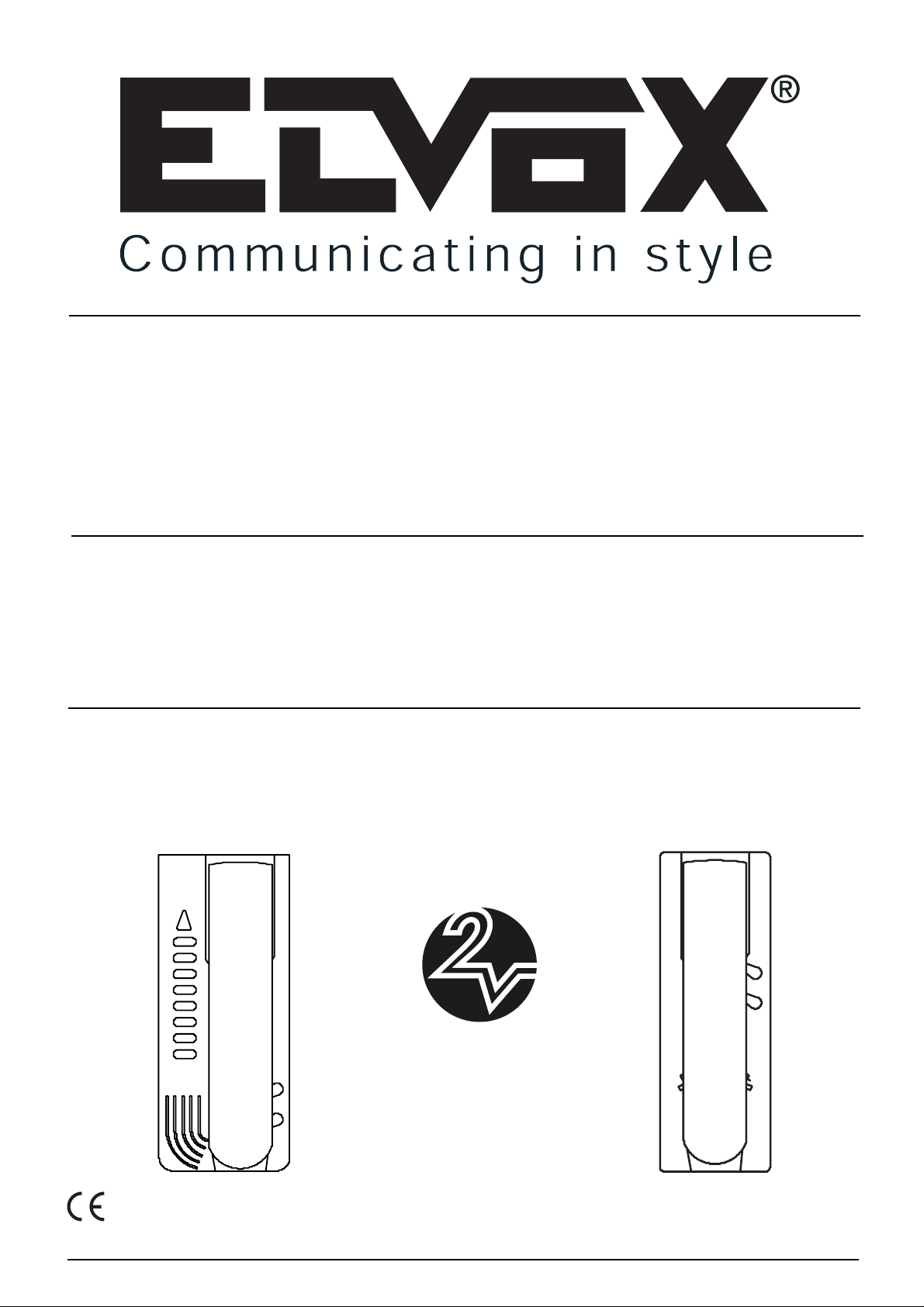
Premere il tasto PROG. rilasciarlo e successivamente premere il
tasto corrispondente alla funzione F1 del citofono fino all’accensione
del LED. In caso di Art. 6202/A cortocircuitare i contatti “centrodestra” del connettore (F1-F2) come indicato in Fig. 1. Nel caso sia
collegato l’Art. 6C59 premere il 1° pulsante in alto (funzione F1). Per
l’Art. 887C/A premere il tasto LAMP. Eseguire la chiamata da targa
premendo il tasto relativo nel caso di una targa a pulsanti o comporre il codice e premere il tasto “C” nel caso di una targa a display.
PROGRAMMING AND OPERATION
The following operations must be carried out only after the entrance
panel has been programmed. To program the interphone number,
remove the cover, press the PROG button on the circuit board and
hold down the “SERR.” button. If the procedure has been effected
correctly, the unit will assume programming mode with led (present
on the interphone circuit board) lighting up, at which point “SERR.”
push-button (related to door serr.) can be released.
If the LED does not light up, the sequence must be repeated. The
interphone handset will now enable communication with the stairway
panel so that the latter sends back the interphone code; to send the
programming code press the respective call push-button when using
entrance panels with push-buttons, or enter the code and press the
"C" push-button when using entrance panels with display (the operation must be carried out within 60 seconds).
As the code is transmitted from the panel to the phone, it will be
memorized by the unit and remain stored until further programming,
even in the event of the panel being disconnected from the power
supply. The entryphone switches the LED off in corfirmation of the
programming operation. In case of installations with several entries,
the connector for the entrance panel interphone riser must be removed, leaving only one entrance panel in operation for the programming phase. This operation can be repeated any number of times,
using other numbers between 0001 and 9999.
Programming the 2nd interphone in parallel (carry out the programming after that of the 1st interphone)
NOTE: It is not possible to connect more than two interphones or
monitors in parallel.
Press the PROG. push-button, release it and then press the pushbutton corresponding to the interphone F1 function until the LED
lights up. When using type 6202/A short-circuit the "centro-destra"
(centre-right) connector (F1-F2) as indicated in Fig. 1. If Art. 6C59 is
connected , press the first push-button at the top (Function F1). With
type 887C/A press the "LAMP" push-button. Carry out the call from
the panel by pressing the respective push-button (when using
entrance panels with push-buttons) or enter the code and the press
the "C" push-button (when using entrance panels with display).
I
GB
Serie 8870
L’art. 887C/A è un citofono della serie Digit 2 Video da parete. Il
citofono Art.887C/A non dispone di serie della funzione chiamata
fuoriporta. Fornito di 2 pulsanti, 1 per apertura serratura e 1 per la
funzione ausiliaria F1. Per utilizzare la funzione chiamata fuoriporta
inserire l’accessorio Art. 6169/Acome da schema variante 6.
Morsettiera di collegamento
1,2) Linea digitale per tramissione/ricezione, fonica, alimentazione
3) Uscita per ripetizione chiamata con relè Art. 170/101
-) Comune
FP) Morsetto per collegamento pulsante per chiamata fuoriporta
Connettori
BL, BI Collegamento microtelefono (filo blu e bianco)
C Comune altoparlante di chiamata
A+ Collegamento altoparlante di chiamata per massima
potenza
A- Collegamento altoparlante di chiamata per suoneria
attenuata
Series 8870
Type 887C/A is a surface wall-mounted interphone from the Digit 2
Video series. Art. 887C/A does not dispose as standard of the outdoor call function. Provided with 2 push-buttons, 1 for lock release
and 1 for auxiliary function F1. To use the outdoor call functioon
insert the accessory type 6169/A as per wiring diagram on variation
6.
Connection terminal
1,2)
Digital line for transmission/reception, audio line, supply voltage
3) Output for call repetition with relay Art. 170/101.
-) Common
FP) Terminal for connection of outdoor call.
Connectors
BL, BI Handset connection (blue and white wire)
C Common wire for call loudspeaker
A+ Call louspeaker connection for maximum power
A- Call loudspeaker connection for attenuated chime
2
Page 3
3
Série PETRARCA
Les art. 6202/A série PETRARCA sont des postes d'appartement de
la série Digit 2 Video. Il peuvent être combiné avec les moniteurs de
la série Petrarca (art. 6002) à l'aide de brides ou d'un kit de transformation. Les fonctions supplémentaires F1, F2 sont utilisables au
moyen d’une paire de bouton-poussoirs supplémentaires Art. 6C59.
Le poste d'appartement Art. 6202/A ne dispose
de série
pas de la
fonction "Appel porte palière" et doit être utilisé exclusivement avec
plaques de rue "DIGIT 2 VIDEO".
N.B. La fonction appel porte palière peut être insérée dans le poste
d'appartement Art. 6202 en utilisant l'accessoire Art. 6169.
Bornier
1,2)
Ligne digital pour transmission/réception, phonique, alimentation.
3) Ligne sortie répétition appel pour relé Art. 170/101.
Connecteurs
F1-F2 Pour fonctions auxiliaires F1 et F2 à connecter à deux
boutons art. 6C59.
CH FP-F3 Pour raccordement bouton-poussoir appel porte paliè-
re au de l’Art. 6169.
Monit. Pour raccorder la carte d'interconnexion moniteur.
BL,BI Raccordement combiné (fil bleu et blanc)
CA Commun haut-parleur d'appel
A+ Raccordement haut-parleur d'appel pour puissance
maximale
A- Raccordement haut-parleur d'appel pour sonnerie atte-
nuée.
Serie PETRARCA
Bei Apparate, Art. 6202/A Serie PETRARCA, handelt es sich um
Sprechanlagen der Serie Digit 2 Video. Sie können mit den
Monitoren der Serie Petrarca (Art. 6002) mit Hilfe der Montagebügel
oder eines Umrüstbausatzes kombiniert werden. Die
Zusatzfunktionen F1, F2 und Außentürfunktion werden über das
Zusatztastenpaar Art. 6C59 betätigt.
Das Haustelefon Art. 6202/A verfügt nicht seriemässig über die
"Wohntürruf"-Funktion und ist nur mit "DIGIT 2 VIDEO"
Klingeltableaus einzubauen.
HINWEIS: Die Wohntürruffunktion kann bei Haustelefon Art. 6202
mittels des Zubehörs Art. 6169 integriert werden.
Anschlussklemmenleiste
1,2) Digitalleitung für Übertragung/Empfang, Sprechleitung,
Speisung
3) Ausgangsleitung Wahlwiederholung für Relais, Art. 170/101
Steckverbinder
F1-F2 Für Hilfsfunktionen F1 und F2, die an ein Paar Tasten
Art. 6C59 anzuschließen sind.
CH FP-F3 Anschluss Taste Etagenruf durch Art. 6169.
Mors. Anschluss Kopplungsplatine für Monitor.
BL, BI Anschluss Hörer (blau/weißer Draht)
CA Gemeinsamer Kontakt Ruflautsprecher
A+ Anschluss Ruflautsprecher für max. Leistung
A- Anschluss Ruflautsprecher für Läutwerk leise
D
Série 8870
L'Art. 887C/A est un poste d'appartement de la série Digit 2 Vidéo pour
montage mural en saillie.
L'Art. 887C/A ne dispose pas de série de la
fonction appel porte palière.
Fourni avec 2 boutons-poussoirs, 1 pour
ouverture gâche et 1 pour la fonction auxiliaire F1.
Pour utiliser la fonction d'appel porte palière insérer l'accessoire Art.
6169/A selon le schéma dans la variante n. 6.
Bornier
1,2)
Ligne digital pour transmission/réception, phonique, alimentation.
3) Sortie pour répétition appel avec relé Art. 170/101.
Connecteurs
BL,BI Raccordement combiné (fil bleu et blanc)
C Commun haut-parleur d'appel
A+
Raccordement haut-parleur d'appel pour puissance maximale
A- Raccordement haut-parleur d'appel pour sonnerie attenuée
Serie 8870
Art.887C/A ist ein Ap-Haustelefon Baureihe Digit 2 Video. Art. 887C/A
verfügt nicht serienmässig über die Funktion Wohntürruf. Mitgeliefert
mit 2 Tasten, 1 für die Türöffnung und 1 für die F1 Zusatzfunktion.
Zur Verwendung der "Wohntürruf"-Funktion das Zubehör Art. 6169/A,
wie in Sonderschalplan - Variante 6 gezeigt, einbauen.
AnschlußKlemmen
1,2) Digitallinie für Übertragung/Empfang, audio line,
Spannungsversorgung
3) Ausgang für Rufwiederholung mit Relais Art. 170/101.
Verbinder
BL,BI Höreranschluß (blauer und weisser Draht)
C Gemeinsamer Draht für Ruflautsprecher
A+ Ruflautsprecheranschluß für maximum Stromstärke.
A- Ruflautsprecheranschluß für abgeschwächte Klingel
F
Fig. 1
Page 4
Serie PETRARCA
Los Art. 6202/A serie PETRARCA son teléfonos de la serie Digit 2
Video. Pueden ser acoplados a los monitores de la serie Petrarca
(art. 6002) por medio de soportes o de kits de transformación. Las
funciones suplementarias F1, F2 son utilizables por medio de un par
de pulsadores suplementarios Art. 6C59.
El teléfono Art. 6202/A no dispone de serie de la función "Llamada
puerta apartamiento" e debe ser utilizado exclusivamente con las
placas "DIGIT 2 VIDEO".
N.B. La función llamada puerta apartamiento puede ser integrada en
el Art. 6202 por medio del accesorio Art. 6169.
Regletas de conexiones
1,2) Línea digital para transmisión/recepción, fónica, alimentación.
3) Línea de salida repetición llamada para relé Art. 170/101.
Conectores
T1 Para funxiciones auxiliares F1 y F2, para conectar a un
par de pulsadores art. 6C59.
CH FP-F3 Para conexionado pulsador llamada puerta apartamien-
to utilizar el Art. 6169.
Mors. Para conectar a la ficha de interconexión monitor.
BL,BI Conexionado microteléfono (hilo azul e blanco)
CA Común altavoz de llamada
A+ Conexionado altavoz de llamada para potencia máxima
A- Conexinado altavoz de llamada para timbre atenuado.
Serie PETRARCA
Os art. 6202/A série PETRARCA são interfones da serie Digit 2
Video. Poden ser unidos aos monitores da série Petrarca (art. 6000 e
6003) por meio de suportes ou de kits de transformação. As funções
suplementares F1, F2 são utilizadas por meio dum par de botões
suplementares Art. 6C69.
O telefone Art. 6202/Anão dispõe de série
da função "Chamada no patamar" e tem de ser utilizado exclusivamente com botoneiras "DIGIT 2 VIDEO".
N.B. A função chamada no patamar pode ser integrada no telefone
Art. 6202 utilizando o Art. 6169.
Caixa de ligação
1,2) Linha digital para transmisão/recepção, fónica, alimentação.
3) Linha de saída repetição chamada para relé Art. 170/101.
Conetores
T1 Para funções auxiliares F1 e F2, para ligar a um par de
botões art. 6C59.
CH FP-F3 Para ligaçãodo botão do chamada no patamar.
utilizar o Art. 6169.
Mors. para ligação placa de interligação monitor.
BL,BI Ligação punho (fio azul e branco)
CA Comúm altifalante de chamada
A+ Ligação altifalante de chamada para potência máxima
A-
Ligação altifalante de chamada para campainha atenuada.
E
P
4
PROGRAMMIERUNG UND BETRIEB
Die nachstehend beschriebenen Vorgänge dürfen erst nach der
Programmierung des Klingeltableaus durchgeführt werden. Um die
Nummer der Innensprechanlage zu programmieren, die Abdeckung
abnehmen, die Taste "PROG" am Schaltkreis drücken; anschließend
die Taste "SERR" (Türöffner) drücken und gedrückt halten. Wurde
der Vorgang korrekt ausgeführt, wechselt die Sprechanlage auf den
Programmiermodus und die LED des Sprechanlagenkreises leuchtet
auf. In diesem Augenblick kann die Taste "SERR" (Türöffner) losgelassen werden. Falls die LED nicht aufleuchtet, den Vorgang wiederholen. Über den Hörer des Türsprechgeräts besteht nun
Verbindung mit dem Klingeltableau zur Übertragung des Kodes der
zu programmierenden Innensprechstelle; zur Übertragung des
Programmiercodes, wenn die Tastenklingeltableaus verwenden worden die entsprechende Ruftaste drücken, oder, falls von
Displayklingeltableaus den Code eingeben und die "C" Taste drücken
(das Verfahren muss innerhalb 60 Sekunden durchgefüht werden).
Wenn der vom Klingeltableau kommende Kode an der
Innensprechstelle eingeht, wird er von letzterer gespeichert und
bleibt bis zur nächsten eventuellen Programmierung im Speicher
erhalten - auch bei Stromausfall. Die Innensprechstelle ausschaltet
die LED die erfolgte Programmierung. Bei Anlagen mit mehr als
einem Eingang muss der Steckverbinder der InnensprechstellenSteigleitung der Klingeltableaus herausgezogen werden, um - für die
Dauer der Programmierung - nur eines in Funktion zu lassen. Das
Programmierverfahren kann mehrmals mit Zahlen zwischen 0001
und 9999 wiederholt werden.
Programmierung der zweiten Taste parallel geschaltet (die
Programmierung durchführen nach der Programmierung der 1°
Taste).
HINWEIS: Mehr als 2 parallel geschaltete Haustelefone oder
Monitore können nicht angeschlossen werden.
Die Taste "PROGRAM" drücken, sie loslassen und dann die der F1
Funktion entsprechende Taste bis die LED erlischt, drücken.
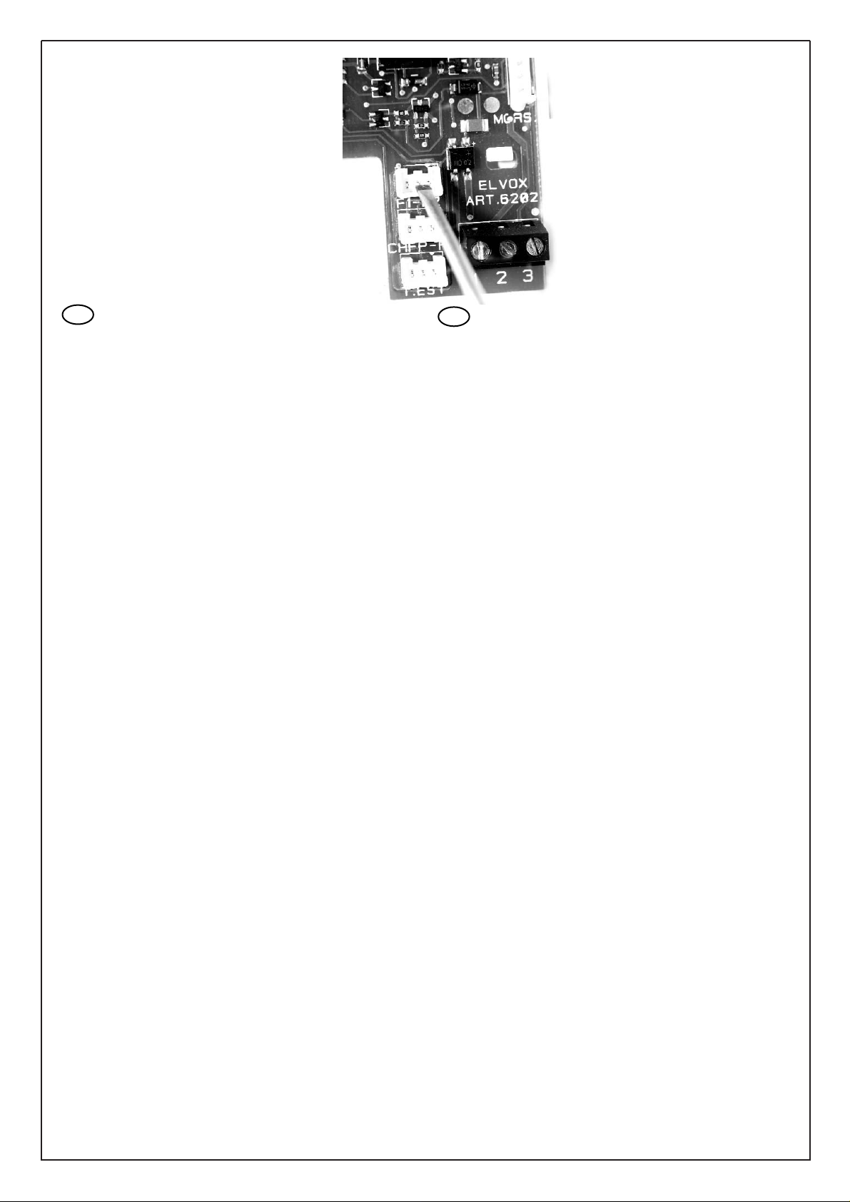
Soll ein Art. 6202/A angebracht werden, so die "centro-destra"
(Zentrum-recht) Kontakte des Verbinders (F1-F2) wie in Abbildung
gezeigt, kurz-schliessen. Falls eines Arts. 6C59 die 1° Taste oben
(Funktion F1) drücken. Mit Art. 887C/A die "LAMP"-Taste drücken.
Den Ruf aus dem Klingeltableau durch Drücken der entsprechenden
Taste (beim Klingeltableau mit Tasten) durchführen oder (beim
Klingeltableau mit Display) den Code eingeben und dann die "C"
Taste drücken.
PROGRAMMATION ET FONCTIONNEMENT
Les opérations qui suivent ne doivent être effectuées qu’après la
programmation de la plaque. Pour programmer le numéro du poste,
retirer le couvercle, presser le bouton “PROG” se trouvant sur le circuit puis appuyer sur le bouton “SERR.” en gardant le doigt dessus.
Si le procédé a été effectué correctement, le poste d’appartement
entre en programmation en allumant la diode LED presente dans le
circuit du poste d’appartement. A ce même instant, relâcher le bouton-poussoir “SERR.” (relatif à la gâche). Si la diode ne s’allume
pas, répéter l’opération. Maintenant, avec le combiné du poste, communiquer avec la plaque de l’escalier afin que le code relatif au
poste programmé soit envoyé; pour envoyer le code de programmation appuyer sur le bouton-poussoir relatif en cas de plaques de rue
avec boutons-poussoirs, ou introduire le code et appuyer sur le bouton-poussoir "C" en cas de plaques avec viseur (l'opération doit être
effectuée d'ici les 60 secondes). Lorsque le code qui provient de la
plaque arrive au poste, ce dernier le mémorise et le maintient
jusqu’à la programmation suivante, même durant les phases avec
absence du courant qui alimente l’installation. Le poste éteint la LED
pour confirmer que l’appel a eu lieu. En cas d’installations avec des
escaliers disposant de plusieurs entrées, extraire le connecteur relatif au montant/postes des plaques, pour en laisser une seule en service et uniquement pour la phase de programmation. L’opération de
programmation peut être répétée plusieurs fois avec des numéros
compris entre les valeurs 0001 et 9999.
Programmation 2ème poste d'appartement en parallèle (effectuer la programmation après celle du 1er poste d'appartement).
N.B On ne peut pas raccorder plus de 2 postes d'appartement ou
moniteurs en parallèle.
Appuyer sur le bouton-poussoir PROGR., le relâcher et ensuite
appuyer sur le bouton-poussoir correspondant à la fonction F1 du
poste d'appartement jusqu'à ce que la LED s'allume. Lorsqu'on utilise l'Art. 6202/A court-circuiter les contacts "centro-destra" (centredroit) du connecteur (F1-F2) comme indiqué dans la Fig. 1. Si l'on
raccorde l'Art. 6C59 appuyer sur le 1er bouton-poussoir en haut
(fonction F1). En utilisant
l'Art. 887C/A appuyer sur
le bouton-poussoir
"LAMP". Effectuer l'appel
depuis la plaque en
appuyant sur le relatif
bouton-poussoir (lorsqu'on utilise une plaque
de rue avec boutonpoussoir) ou introduire le
code et appuyer sur le
bouton-poussoir "C" (en
cas de plaques avec
viseur).
Fig. 1
Page 5

5
PROGRAMACIÓN Y FUNCIONAMIENTO
Las operaciones que siguen deben ser efectuadas solamente
después de la programación de la placa. Para programar el número
del interfono quitar la tapa, presionar el pulsador “PROG” presente
en el circuito y luego presionar y mantener presionado el pulsador
“SERR.”. Si el procedimiento ha sido efectuado correctamente, el
teléfono entra en programación encendiendo el diodo LED presente
en el circuito del teléfono. En este instante se puede soltar el pulsador “SERR.” (relativo a la cerradura). Si el diodo no se ilumina, repetir la operación. Ahora con el microinterfono del interfono es posible
comunicar con la placa segundaria y enviar el código relativo al
interfono que hay que programar (la operación deve ser efectuada
dentro los 60 segundos). Cuando el código proveniente de la placa
llega al interfono, éste lo memoriza y lo mantiene memorizado hasta
la próxima eventual programación, también durante las fases de
falta de tensión de alimentación en la instalación. El interfono apaga
el LED para confirmar que la programación ha sido efectuada.
Cuando hay instalaciones con escaleras con más de una entrada,
extraer el conector relativo al montante interfonos de las placas,
dejando una sola placa en función para la sola fase de programación. La operación de programación puede ser repetida varias veces
con números comprendidos entre los valores 0001 y 9999.
Programación 2do teléfono en paralelo (efectuar la programación después de aquella del 1er teléfono).
N.B. No se pueden conectar más de 2 teléfonos o monitores en
paralelo.
Presionar il pulsador "PROGRAM", soltarlo y sucesivamente pulsar
el pulsador correspondiente a la función F1 del teléfono hasta que el
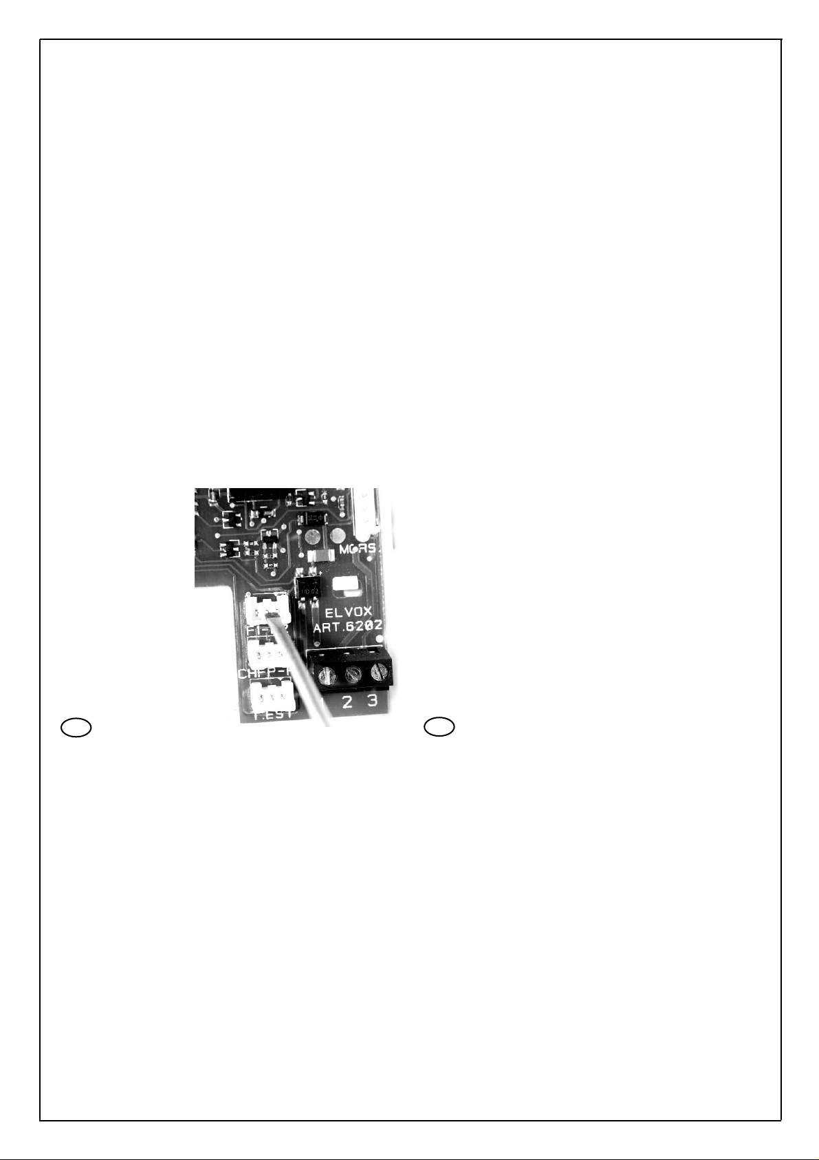
LED se encienda. Utilizando el Art. 6202/Acortocircuitar los contactos "centro-destra" (centro-derecha) del conector (F1-F2) como indica la Fig. F 1. Si se conecta el Art. 6C59 presionar el 1er pulsador
arriba (función F1). En el Art. 887C/A presionar el pulsador "LAMP".
Efectuar la llamada desde la placa presionando el relativo pulsador
(en caso de placa con pulsadores), o (en caso de placa con display)
introducir el código y pulsar el pulsador "C".
PROGRAMAÇÃO E FUNCIONAMENTO
As operações que se seguem só devem ser efectuadas depois da
programação da botoneira. Para programar o número do telefone
retirar a cobertura, premir o botão "PROG" existente no circuito e, a
seguir, premir e manter premido o botão "SERR.". Se o procedimento foi efetuado corretamente, o telefone entra em programação
acendiendo o diodo LED presente no circuito do telefone.
Neste instante, pode-se libertar o botão "SERR."(referido ao trinco).
Se o LED não se acender, repetir esta operação. Agora, através do
telefone, é possível comunicar com a botoneira do patamar para que
sejam enviados os códigos referentes ao telefone a programar Para
enviar o código de programação premir o relativo botão de chamada no caso de botoneiras com botões ou, no caso de botoneiras
com visor, introduzir o código e premir o botão "C" (a operação deve
ser efectuada dentro os 60 segundos). Quando o código proveniente
da botoneira chega ao telefone, este memoriza-o e mantém-no até à
próxima programação, mesmo durante as fases de falha na tensão
de alimentação da instalação. O telefone desliga o LED para confirmar o sucesso da programação. No caso de instalações com mais
de uma entrada, é necessário extrair o conector referente à coluna
montante dos telefones das botoneiras, deixando apenas uma em
funcionamento para a fase de programação. A operação de programação pode ser repetida várias vezes com números compreendidos
entre os valores 0001 e 9999.
Programação do 2° telefone em paralelo (efectuar a programação depois daquela do 1° telefone).
N.B. Não pode-se ligar mais do que 2 telefones ou monitores em
paralelo.
Premir o botão "PROGR.", soltá-lo e sucessivamente premir o botão
relativo à função F1 do teléfone até o LED se acender. No caso de
Art. 6202/A curto-circuitar os contactos "centro-destra (centro-direita)
do conector (F1-F2) como indica a figura 1. Se fôr ligado o Art. 6C59
premir o 1° botão arriba (função F1). Quando utiliza-se o Art. 887C/A
premir o botão "LAMP". Efectuar a chamada da botoneira premindo
o referido botão (no caso de botoneira com botões) ou (no caso de
botoneiras com visor) introduzir o código e premir o botão "C".
Serie 8870
El Art. 887C/A es un teléfono de la serie Digit 2 Video para montaje
de superficie.
El Art. 887C/Ano dispone de serie de la función llama-
da puerta apartamiento.
Suministrado con 2 pulsadores, 1 para la
apertura de la cerradura y 1 para la función auxiliar F1.
Para utilizar la función llamada puerta apartamiento insertar el accesorio Art. 6169/Acomo muestra el esquema en la variación 6.
Regletas de conexiones
1,2) Línea digital para transmisión/recepción, fónica, alimentación.
3) Salida para repetición llamada con relé Art. 170/101.
-) Común
FP) Borne para el conexionado del pulsador para llamada puerta
apartamiento.
Conectores
BL,BI Conexionado microteléfono (hilo azul e blanco)
C Común altavoz de llamada
A+ Conexionado altavoz de llamada para potencia máxima
A- Conexinado altavoz de llamada para timbre atenuado.
Série 8870
O Art. 887C/A é um interfone da série Digit 2 Video com chamada
no patamar para montagem saliente. O Art. 887C/A não dispõe de
série da função chamada no patamar. Fornecido com dois botões, 1
para a abertura do trinco e 1 para a função auxiliar F1.
Para utilizar a função chamada no patamar inserir o acessório Art.
6169/A como mostra o esquema na variante 6.
Caixa de ligação
1,2) Linha digital para transmisão/recepção, fónica, alimentação.
3) Saída para repetição chamada com relé Art. 170/101.
-) Comum
FP) Terminal para ligação do botão para chamata no patamar.
Conetores
BL,BI Ligação punho (fio azul e branco)
C Comúm altifalante de chamada
A+ Ligação altifalante de chamada para potência máxima
A- Ligação altifalante de chamada para campainha atenuada.
Fig. 1
Page 6

6
.732
DISTRIBU
ORE
V
I
D
E
O
SE
R
I
E
V
I
D
I
GI
T
2
VIDEO DISTRIBU
OR VI-DIGIT2W SERIE
V3
V3
OU
M
O
N
ANT
V4
V4
V1
V1
V2
V2
IN MON
ANT
MONTANTE MONITOR - MONITOR CABLE RISER - MONTANT MONITEURS
MONITOR-STEIGLEITUNG - MONTANTE MONITOR - COLUNA MONTANTE DOS MONITORES
Rif schema - Ref. diagram - Réf. schéma - Siehe Plan - Ref. esquema - Refª esquema vc4412R1
MONTANTE MONITOR
MONITOR CABLE RISER
MONTANTMONITEUR
MONITOR-STEIGLEITUNG
COLUNA MONTANTE DOS MONITORES
Alla targa elettronica
To the electronic entrance panel
À la plaque de rue électronique
Zum elektronischen
Klingetableau
Hacia la placa electrónica
Para a botoneira eletrónica
Distributore
Distributor
Distributeur
Verteiler
Distribuidor
Art. 732D
A- Alimentatore
Power supply
Alimentation
Netzgerät
Alimentador
Art. 6582
A
B
CAVO -CABLE
CÂBLE - KABEL
CABLE - CABO
ART. 732F
CAVO -CABLE
CÂBLE - KABEL
CABLE - CABO
ART. 732F
A
MONTANTE IN - CABLE RISER IN
STEIGLEITUNG EINGANG - MONTANT IN
MONTANTE IN
MONTANTE OUT - CABLE RISER OUT
STEIGLEITUNG AUSGANG - MONTANT OUT
MONTANTE OUT
DISTRIBUTORE-DISTRIBUTOR
DISTRIBUTEUR-VERTEILER
DISTRIBUIDOR Art. 732D
Ponticelli presenti nel distributore Art. 732D. Da
togliere solo se viene usata la sua uscita vicina.
Jumpers on splitter Art. 732D. To remove only if its
close output is used.
Barrettes presentes sur le distributeur Art. 732D. À
enlever seulement si l'on utilise sa sortie prochaine
Jumper im Verteiler Art. 732D. Nur entfernen, wenn
der entsprechende Ausgang verwendet wird.
Puentes presentes en el distribuidor Art. 732D, Para
quitar sólo si se utiliza su salida cercana.
Pontes presentes no distribuidor Art. 732D, para reti-
rar só se usa-se a sua saída vezinha.
MONTANTE OUT
MONTANTE IN
RETE-MAINS-RÉSEAU
NETZ-RED-REDE
RETE-MAINS-RÉSEAU
NETZ-RED-REDE
CAVO -CABLE
CÂBLE - KABEL
CABLE - CABO
ART. 732F
X Nell’ultimo distributore inserire il ponticello A anche se
è usata la sua uscita vicina.
In last distributor insert jumper A even if its close output is used
Dans le dernier distributeur insérer la barrette Amême
si sa sortie prochaine est utilisée.
Im letzten Verteiler den Jumper "A" einsetzen, auch
wenn der entsprechende Ausgang verwendet wird.
En el último distribuidor insertar el puente a.también si
se utiliza su salida cercana.
No ultimo distribuidor inserir a ponte “A” mesmo se utiliza-se a sua saída vezinha.
X
B- Videocitofono
Moniteur
Art. 6002+6202/A+6145
D
B
C
C- Citofono
Phone
Poste
Haustelefon
Interfono
Telefono
Art. 887C/A
D- Citofono
Phone
Poste
Haustelefon
Interfono
Telefono
Art. 6202/A
-+U+I B CA PRID
1
2
3
Mors.
To phone
L1
L2
+
To monitor
1
2
3
Mors.
OUT
V4V4 V3V3
BA
V4
V
4
O
U
T M
O
N
T
A
N
T
E
V3
V
3
R
I
T
A
L
Y
D
AR
IS
T
R
IB
T
V
U
ID
.7
T
E
O
O
3
R
D
E
2
V
IS
D
ID
T
R
E
IB
O
U
S
T
E
O
R
R
IE
V
V
I-D
I-D
IG
IG
IT
I
T
2
2
W
W
S
E
R
IE
S
V
1
V
1
IN
M
O
N
T
A
N
T
E
V
2
V
2
DC
IN
V1 V1 V2V2
1
2
3
To phone
To monitor
L1
L2
+
+I- +U A B C PRID
1
2
3
Mors.
V4V4 V3V3
OUT
AB
CD
INV1 V1 V2V2
Page 7

7
MONTANTE CITOFONI
INTERPHONE CABLE RISER
MONTANTPOSTES
HAUSTELEFONEN-STEIGLEITUNG
MONTANTE INTERFONOS
COLUNA MONTANTE DOS TELEFONES
Citofono
Phone
Poste
Haustelefon
Interfono
Telefono
Art. 6202/A
Citofono
Phone
Poste
Haustelefon
Interfono
Telefono
Art. 6202/A
Citofono
Phone
Poste
Haustelefon
Interfono
Telefono
Art. 887C/A
Citofono
Phone
Poste
Haustelefon
Interfono
Telefono
Art. 887C/A
MONTANTE CITOFONI - INTERPHONE CABLE RISER - MONTANT POSTES
HAUSTELEFONEN-STEIGLEITUNG - MONANTE INTERFONOS - COLUNA MONTANTE DOS TELEFONES.
Rif schema - Ref. diagram - Réf. schéma - Siehe Plan - Ref. esquema - Refª esquema vc4412R1
Alla targa elettronica
To the electronic entrance panel
À la plaque de rue électronique
Zum elektronischen Klingetableau
Hacia la placa electrónica
Para a botoneira eletrónica
Mors.
Mors.
1
2
3
1
2
3
L2
L1
1
2
3
1
2
3
L2
L1
Page 8

8
VARIANTE-VERSION-SONDERSCHALTUNG-VARIACIÓN 1
Collegare suonerie supplementari a timpano .
Si possono collegare suonerie supplementari funzionanti a 12V c.a. o
rete c.a. tranite relè 170/101. Collegare il relè come da schema il
morsetto 1 del relè andrà collegato tra il morsetto 1 o 2 del citofono, il
morsetto esatto corrisponde al positivo tra i morsetti 1 e 2. Individuare
il morsetto esatto misurando con un tester la polarità dei due morsetti.
Connect additional chimes.
Additional chimes powered by 12V A.C. or A.C. mains through relay
type 170/101 may be connected. Connect a realy according to wiring
diagram; terminal 1 of relay must be connected to terminal 1 or 2 of
interphone, terminal “exact” correspond to “positive” between terminals 1 and 2. Specify the “exact” terminal by measuring the polarity of
the two terminals a tester or, empirically, proving one or the other
with the relay.
Raccorder sonneries supplémentaires.
On peut connecter sonneries supplémentaires fonctionant à 12V c.a
ou avec réseau c.a. au moyen du relais 170/101.
Raccorder le relais selon le schéma; la borne 1 du relais doit être raccordé entre la borne 1 ou 2 du poste d’appartement; la borne « exact
» correspond au « positif » entre les bornes 1 et 2. Individuer la borne
“exact” en misurant avec un testeur la polarité des deux bornes ou
empiriquement, en essayant une ou l’autre avec le relais.
SUONERIAATIMPANO
BELL
SONNERIES
BELL
TIMBRES
CAMPAÍNHA
ALIMENTAZIONE SUONERIE
BELL SUPPLY
ALIMENTATION SONNERIES
VERSORGUNG DER KLINGELN
ALIMENTACIÓN DE LOS TIMBRES
ALIMENTAÇÃO CAMPAÍNHA
RELE’-RELAY-RELAIS
Art. 170/101
Carico massimo-Max. Load
Charge max.-Max. Last
Carga máxima 3A - 230V
CITOFONO
PHONE
POSTE
HAUSTELEFON
INTERFONO
TELEFONO
Art. 6202/A
Art. 887C/A
Zusatzlautstärke anschließen.
Zusatzlautstärke versorgt von 12V A.C. oder C.A. Netz durch 170/101
können angeschlossen werden. Das Relais wie in Schalplan anschließen; Klemme 1 des Relais zwischen Klemmen 1 oder 2 des
Hasutelefons anschließen; die „exact“ Klemme entspricht dem positiven Draht zwischen Klemmen 1 und 2. Die Klemme “exak”durch
Messen der Polarität der zwei Klemmen mit einem Tester feststellen
oder, empirisch, durch Überprüfen einer oder anderer mit dem Relais.
Conectar timbres suplementarios.
Se pueden conectar timbres suplementarios funcionantes a 12V c.a.
o red a c.a. por medio del relé 170/101. Conectar el relé como muestra el esquema; el borne 1 del relé debe ser conectado entre los bornes 1 o 2 del interfono, el borne “exacto” corresponde al “positivo”
entre los bornes 1 y 2. Individuar el borne “exacto” medindo con un
tester la polaridad de los dos bornes o, empíricamente, probando uno
o el otro con el relé.
Ligar campainhas suplementares.
Podem-se ligar camplainhas suplementares funcionantes com 12V
c.a. ou com rede em c.a. através do relé Art. 170/101. Ligar o relé
como mostra o esquema; o terminal 1 do relé deve ser ligado ao terminal 1 ou 2 do interfone; o terminal “exacto” corresponde ao “positivo” entre os terminais 1 e 2. Individuar o terminal “exacto” medindo
com um tester a polaridade dos dois terminais o empiricamente, provando um ou o outro com o relé.
Mors.
RC 51C2 3415
1
2
L1
L2
3
1 o 2
Page 9

9
CITOFONO
PHONE
POSTE
HAUSTELEFON
INTERFONO
TELEFONO
Art. 6202/A + 6C59
VARIANTE-VERSION-SONDERSCHALTUNG-VARIACIÓN 2
Collegamento pulsante supplementare (F1, F2) mediante 6C59
Collegare il pulsante al citofono tramite l’Art. 6C59; l’Art. 6C59 andrà collegato al citofono tramite il connettore “F1, F2” per le funzioni supplementari. Le funzioni si possono attivare solo tramite i pulsanti del citofono, per utilizzare pulsanti esterni vedi variante 3.
For connection of additional push-button (F1, F2) with Art. 6C59
Connect push-button by means of type 6C59. Type 6C59 must be connected to interphone by means of connector "F1, F2" for additional functions. The functions can be activated only by means of the interphone push-buttons. To use external push-buttons see variation 3.
Raccordement du bouton-poussoir supplémentaire (F1, F2)
Raccorder le bouton-poussoir au poste d'appartement par l'intermédiaire de l'Art. 6C59. L'Art. 6C59 doit être raccordé au connecteur "F1, F2"
pour les fonctions supplémentaires. Les fonctions peuvent être activées seulement au moyen des boutons-poussoirs du poste d'appartement.
Pour utiliser boutons-poussoirs externes voir variante 3.
Anschluss für die Zusatztaste (F1, F2) mit Art. 6C59
Die Taste ans Haustelefon durch den Art. 6C59 anschliessen. Art. 6C59 muss ans Haustelefon durch den "F1, F2" Steckverbinder für
Zusatzfunktionen. Die Funktionen können durch die Haustelefontasten aktiviert werden. Zur Verwendung der Externtasten siehe Variante 3.
Conexionado pulsador suplementario (F1, F2) por medio del Art. 6C59.
Conectar el pulsador al teléfono por medio del Art. 6C59; el Art. 6C59 debe ser conectado al teléfono por medio del conector "F1, F2" para las
funciones suplementarias. Las funciones se pueden activar por medio de los pulsadores del teléfono. Para utilizar los pulsadores externos ver
variación 3.
Ligação para botão suplementar (F1, F2) com Art. 6C59
Ligar o botão ao telefone através do Art. 6C59. O Art. 6C59 deve ser ligado ao telefone por meio do conector "F1, F2" para as funções suplementares. As funções podem ser activadas só através dos botões do telefone. Para utilizar botões externos ver variante 3.
VARIANTE-VERSION-SONDERSCHALTUNG-VARIACIÓN 3
Schema per il collegamento di 2 pulsanti
supplementari esterni per funzioni ausilirie
F1 e F2 mediante Art. 6C59 e relè Art.
170/001.
N.B. I relè devono essere posti nelle immedia-
te vicinanze dei citofoni.
Circuit diagram for connection of 2 supplementary external pushbuttons for auxiliary
functions F1 and F2, by means of type
6C59 and relay type 170/001.
N.B. The relays must be installed very close to
the interphones.
Schéma de branchement des 2 boutons
supplémentaires externes associés aux
fonctions accessoires F1 et F2, au moyen
de l'Art. 6C59 et relais Art. 170/001.
N.B. Les relais doit être installés bien près des
postes d'appartement.
Schema für den Anschluss von 2 externen
Zusatztasten für Hilfsfunktionen F1 und F2,
durch Art. 6C59 und Relais Art. 170/001.
HINWEIS: Die Relais mussen sehr nahe der
Haustelefonen angebracht werden.
Esquema de conexionado de 2 pulsadores
suplementarios externos para funciones
auxiliares F1 y F2 por medio del Art. 6C59
y relé Art. 170/001.
N.B. Los relés deben ser colocados muy
cerca de los teléfonos.
Esquema de ligação de 2 botões suplementares externos para funções auxiliares
F1 e F2, por meio do Art. 6C59 e relé Art.
170/001
N.B. Os relés devem ser colocados muito
vezinho aos telefones.
RETE-NETWORK
RÉSEAU-NETZ
RED-REDE
ART. 6582
ALIMENTATORE
POWER SUPPLY
ALIMENTATION
NETZGERÄT
ALIMENTADOR
B- Pulsante per funzione F1
Push-button for function F1
Bouton fonction F1
Taste für Funktion F1
Pulsador para función F1
Botão para função F2
A- Pulsante per funzione F2
Push-button for function F2
Bouton fonction F2
Taste für Funktion F2
Pulsador para función F2
Botão para função F2
RELÈ
RELAY
RELAIS
ART. 170/001
RELÈ
RELAY
RELAIS
ART. 170/001
CITOFONO
PHONE
POSTE
HAUSTELEFON
INTERFONO
TELEFONO
Art. 6202/A + 6C59
N.B. L’alimentatore Art. 6582 è da utilizzare per il pilotaggio dei relè delle funzioni in tutto l’impianto
NOTE: The power supply type 6582 is to be used to
manage some function relays in the whole installation.
N.B. L'alimentation Art. 6852 doit être utilisée pour gérer
quelques relés des fonctions dans toute l'installation.
HINWEIS: Netzgerät Art. 6582 ist für die Steuerung von
einigen Funktionrelais bei der ganzen Anlage zu nutzen.
N.B. El alimentador Art. 6582 se utiliza para administrar
algunos relés de las funciones en toda la instalación.
N.B. O alimentador Art. 6582 deve ser utilizado para
gerir alguns relés das funções em toda a instalação.
F1
F2
F2F1
C
T2
Art. 6C59
T1
1
2
3
Mors.
C
F1
T2
F2
Art. 6C59
T1
PRI
1
2
FPF2CH
3
F1
Mors.
BACD 12 435 2134
B
L1
L2
A
5-+I+U
Page 10

10
VARIANTE-VERSION-SONDERSCHALTUNG-VARIACIÓN 4
Collegamento pulsante chiamata fuoriporta per l’Art.
6202/A mediante accessorio Art. 6169
Collegare il pulsante fuori porta al citofono tramite l’Art. 6169; l’Art.
6169 andrà collegato al citofono tramite il connettore “CH FP-F3”
Azionando il pulsante fuoriporta il citofono suona con un timbro
differente da quello ottenuto con la chiamata dalla targa esterna.
Connection of push-button for outdoor call for type
6202/A by means of accessory type 6169
Connect the outdoor push-button to the interphone by means of
type 6169; type 6169 must be connected to the interphone by
means of connector “CH - FP- F3”.Pressing the outdoor push-button produces a phone tone different than a call made from the
entrance panel.
Raccordement bouton-poussoir pour appel porte palière pour Art. 6202/A au moyen de l'accessoire Art. 6169.
Raccorder le bouton-poussoir porte palière au poste d’appartement Art. 6169; l’Art. 6169 doit être raccordé au poste d’appartement par l’intermédiaire du connecteur “CH FP - F3”. En apuyant
sur le bouton-poussoir hors de la porte le poste sonne avec une
tonalité differente de celle émise avec l’appel de la plaque externe.
Anschluss der Taste für den Wohntüruf für Art. 6202/A
mittels des Zubehörs Art. 6169.
Die Außentürtaste mittels Art. 6159 am Haustelefon anschließen;
Art. 6169 muß durch Verbinder „CH FP - F3“ am Haustelefon
angeschlossen werden. Wird die Aussentürtaste betätigt werden,
ertönt im Haustelefon ein Rufton, der sich vom Rufton von der
Türstelle unterscheidet.
Conexionado pulsador para llamada puerta apartamiento para el Art. 6202/Apor medio del accesorio Art. 6169.
Conectar el pulsador puerta apartamiento al interfono por medio
del Art. 6169; el Art. 6169 deve ser conectado al interfono por
medio del conector Art. “CH FP - F3”. Presionando el pulsador
puerta apartamiento el monitor suena con un sonido diferente de
aquello obtenido con la llamada desde la placa externa.
Ligação botão para chamada no patamar para o Art.
6202/A através do Art. 6169.
Ligar o botão do patamar ao interfone através do Art. 6169; o Art.
6169 deve ser ligado ao interfone por meio do conetor “CH FP F3”. Premindo o botão no patamar o monitor toca com un som
diferente daquele obtido com uma chamada da botoneira externa.
CITOFONO
PHONE
POSTE
HAUSTELEFON
INTERFONO
TELEFONO
Art. 6202/A + 6169
ALIMENTATORE
POWER SUPPLY
ALIMENTATION
NETZGERÄT
ALIMENTADOR
ART. 6582
RETE-MAINS
RÉSEAU-NETZ
RED-REDE
A - Pulsante fuoriporta
Push-button outside
apartment door
Poussoir à la porte
de l’appartement
Klingeltaste vor
der Wohnung
Pulsador puerta
del apartamento
Botão no patamar
N.B. L’alimentatore Art. 6582 è da utilizzare per il pilotaggio dei relè delle funzioni in tutto l’impianto
NOTE: The power supply type 6582 is to be used to
manage some function relays in the whole installation.
N.B. L'alimentation Art. 6852 doit être utilisée pour gérer
quelques relés des fonctions dans toute l'installation.
HINWEIS: Netzgerät Art. 6582 ist für die Steuerung von
einigen Funktionrelais bei der ganzen Anlage zu nutzen.
N.B. El alimentador Art. 6582 se utiliza para administrar
algunos relés de las funciones en toda la instalación.
N.B. O alimentador Art. 6582 deve ser utilizado para
gerir alguns relés das funções em toda a instalação.
PRI
-+I+U
Art. 6169
CH FP
Mors.
C
+
1
2
3
BACD
A
L1
L2
Page 11

11
VARIANTE-VERSION-SONDERSCHALTUNG-VARIACIÓN 5
Collegamento pulsante di chiamata fuoriporta per Art.887C/A mediante accessorio Art. 6169/A
Collegare i due fili (non polarizzati) ai morsetti FP e - del citofono Art. 887C/A.
Connection of push-button for outdoor call for type 887C/A by means of accessory type 6169/A
Connect the two (not polarized) wires to terminals FP and - of interphone type 887C/A
Raccordement bouton-poussoir pour appel porte palière pour Art. 887C/Aau moyen de l'accessoire Art. 6169/A
Raccorder les deux fils (non polarisés) aux bornes FP et - du poste d'appartement Art. 887C/A.
Anschluss der Taste für den Wohntüruf für Art. 887C/A mittels des Zubehörs Art. 6169/A
Die zwei (nicht polarisierten) Drähte an Klemmen FP und - des Haustelefons Art. 887C/Aanschliessen.
Conexionado pulsador para llamada puerta apartamiento para el Art. 887C/A por medio del accesorio Art. 6169/A
Conectar los dos hilos (no polariizados) a los bornes FP y - del teléfono Art. 887C/A.
Ligação botão para chamada no patamar para o Art. 887C/A através do Art. 6169/A
Ligar os dos fios (não polarizados) aos terminais FP e - do telefone Art. 887C/A
A - Pulsante fuoriporta
Push-button outside
apartment door
Poussoir à la porte
de l’appartement
Klingeltaste vor
der Wohnung
Pulsador puerta
del apartamento
Botão no patamar
CITOFONO
PHONE
POSTE
HAUSTELEFON
INTERFONO
TELEFONO
Art. 887C/A + 6169/A
ALIMENTATORE
POWER SUPPLY
ALIMENTATION
NETZGERÄT
ALIMENTADOR
ART. 6582
RETE-MAINS
RÉSEAU-NETZ
RED-REDE
N.B. L’alimentatore Art. 6582 è da utilizzare per il pilotaggio dei relè delle funzioni in tutto l’impianto
NOTE: The power supply type 6582 is to be used to
manage some function relays in the whole installation.
N.B. L'alimentation Art. 6852 doit être utilisée pour gérer
quelques relés des fonctions dans toute l'installation.
HINWEIS: Netzgerät Art. 6582 ist für die Steuerung von
einigen Funktionrelais bei der ganzen Anlage zu nutzen.
N.B. El alimentador Art. 6582 se utiliza para administrar
algunos relés de las funciones en toda la instalación.
N.B. O alimentador Art. 6582 deve ser utilizado para
gerir alguns relés das funções em toda a instalação.
Art. 6169/A
PRI
+U-+IA
C
-
+
FP
1
2
3
BCD
A
L1
L2
Page 12

12
FILIALE DI MILANO:
Via Conti Biglia, 2 20162 (MILANO)
Tel. 02/6473360-6473561
Fax 02/6473733
E-mail: filialemilano@elvoxonline.it
FILIALE DI TORINO:
Via Albenga, 36/A
Cascine Vica - 10098 Rivoli (TORINO)
Tel. 011/9592829-30 - Fax. 011/9592850
E-mail: filialetorino@elvoxonline.it
FILIALE DI BRESCIA:
Via Isole Lipari, 14 25124 BRESCIA
Tel. 030/225413 - Telefax. 030/225413
E-mail: filialebrescia@elvoxonline.it
FILIALE TOSCANA:
Via Lunga 4/R 50142 FIRENZE
Tel. 055/7322870 - Telefax. 055/7322670
E-mail: filialetoscana@elvoxonline.it
UNI EN ISO 9001
ELVOX COSTRUZIONI
ELETTRONICHE S.p.A.
35011 Campodarsego (PD) - ITALY
Via Pontarola, 14/A
Tel. 049/9202511 r.a. -
Phone international... 39/49/9202511
Telefax Italia 049/9202603
Telefax Export Dept... 39/49/9202601
ELVOX INTERNET SERVICE
E-mail: info@elvoxonline.it
http://www.elvox.com
E-mail export dept:
elvoxexp@elvoxonline.it
ANWEISUNGEN FÜR DEN INSTALLATEUR
- Diese Anweisungen genau lesen, da sie über die Sicherheit beim Einbau, den
Gebrauch und die Pflege informieren.
- Nach dem Auspacken die Unversehrtheit des Geräts feststellen.
- Verpackungsteile (Plastiktüten, Schaumpolystyrol, etc.) von Kindern entfernt halten, da
sie für diese gefärlich sind.
- Die Anlage muß den nationalen Normen entsprechen.
- Es ist notwendig vor dem Netzgerät einen passenden Schutz-und Trennschalter einzubauen.
Vor dem Anschließen des Geräts sicherstellen, daß die Daten des Klingeltableaus mit
denen im Leitungsnetz über einstimmen.
- Dieses Gerät nur für den vorbestimmten Gebrauch verwenden, und zwar für DIGIBUSTürsprechanlagen. Jeder andere Gebrauch ist gefährlich. Der Hersteller übernimmt
keine Verantwortung für beim Mißbrauch des Geräts entstandenen Schaden.
- Vor jeglicher Säuberung oder Nachpflege, das Gerät vom Versorgungsnetz abschalten
(Schaltknopf drücken).
- Im Falle einer Beschädigung und/oder schlechten Funktionierens des Geräts dieses
anhand des Versorgungsnetzschalters abschalten.
- Sich für die eventuelle Reparatur an eine offizielle technische Kundenbetreuungsstelle
wenden. Die Mißachtung dieses Hinweises könnte die Sicherheit des Geräts gefährden.
- Keine Lüftungsschlitze der Geräte verschließen.
- Der Installateur muß nach dem Einbau darauf achten, daß die Anweisungen für den
Benutzer immer an den Geräten vorhanden sind.
- Alle Geräte dürfen nur für den vorbestimmten Gebrauch verwendet werden.
CONSEJOS PARAELINSTALADOR
- Leer atentamente los consejos contenidos en el presente documento en cuanto dan
importantes indicaciones concernientes la seguriad de la intalación, del uso y del
mantenimiento.
- Después de haber quitado el embalaje asegurarse de la integridad del aparato.
- Los elementos del embalaje (bolsos de plástica, etc.) no tienen que ser dejados al
alcance de los niños en cuanto son posibles fuentes de peligro.
- La ejecución de la instalación debe respetar las normas de seguridad en vigor.
- Es oportuno prever antes de la alimentación un interruptor apropiado de secciona-
miento y protección.
- Antes de conectar el aparato asegurarse que los datos de la placa sean los mismos
a los de la red de distrbución.
- Este aparato tendrá que ser destinado solamente al uso para el cual fue expresa-
mente concebido, es decir, para el sistema DIGI-BUS.
- Los otros usos pueden ser considerados impropios y por lo tanto peligrosos.
- El constructor no puede ser considerado responsable de eventuales daños causados
por usos impropios, erróneos e irrazonables.
- Antes de efectuar cualquier operación de limpieza o de mantenimiento, desconectar el
aparato de la red de alimentación eléctrica, apagando el interruptor de la instalación.
- En caso de daño y/o de malo funcionamiento del aparato, quitar la alimentación por
medio del interruptor y no manipularlo.
- Para eventuales reparaciones recurrir solamente a un centro de asistencia técnica
autorizado por el constructor.
- La falta de respeto a lo anteriormente expuesto puede comprometer la seguridad del
aparato.
- No obstruir las aberturas o hendiduras de ventilación o de salida calor.
- El instalador debe asegurarse que las informaciones para el usuario sean presentes
en los aparatos.
- Todos los aparatos que constituyen la instalación deben ser destinados exclusiva-
mente al uso para el cual han sido concebidos.
ADVERTÊNCIAS PARAO INSTALADOR
- Ler atentamente as recomendações contidas neste documento dado que fornecem
importantes indicações no que diz respeito à segurança, utilização e manutenção das
instalações.
- Após abrir a embalagem, verificar a integridade do aparelho. Os elementos da emba-
lagem (sacos de plástico, esferovite, etc.) não devem ser deixados ao alcance de
crianças pois são potenciais fontes de perigo. Aexecução da instalação deve respeitar as normas CEI vigentes.
- É aconselhável aplicar, a montante da alimentação, um interruptor de seccionamento
e protecção apropriados.
- Antes de ligar o aparelho, verificar se os dados da placa correspondem com os da
rede de distribuição.
- Este aparelho só deve ser utilizado em instalações para as quais foi expressamente
concebido, isto é, para sistemas DIGIBUS. Qualquer outra utilização deve ser considerada imprópria e, por conseguinte, perigosa. O construtor não pode ser considerado responsável por eventuais danos provocados por usos impróprios, errados e irracionais.
- Antes de efectuar qualquer operação de limpeza ou de manutenção, desligar o apa-
relho da rede de alimentação eléctrica, através do dispositivo instalado.
- No caso de avaria e/ou mau funcionamento do aparelho, retirar a alimentação
através do interruptor e mantê-lo desligado. Para uma eventual reparação, dirigir-se,
apenas, a um centro de assistência técnica autorizado pelo construtor. O não cumprimento destas recomendações pode comprometer a segurança do aparelho.
- Não obstruir as aberturas ou ranhuras de ventilação ou de dissipação do calor.
- O instalador deve verificar se as informações para o utente estão junto do aparelho.
AVVERTENZE PER L'INSTALLATORE
- Leggere attentamente le avvertenze contenute nel presente documento, che forniscono
importanti indicazioni riguardanti la sicurezza di installazione, d'uso e di manutenzione.
- Dopo aver tolto l'imballaggio assicurarsi dell'integrità dell'apparecchio. Gli elementi dell'imballaggio (sacchetti di plastica, polistirolo espanso, ecc.) non devono essere lasciati
alla portata dei bambini perchè potenziali fonti di pericolo. L'impianto deve essere conforme alle norme vigenti (CEI).
- È necessario installare a monte dell'impianto citofonico o videocitofonico un appropriato
interruttore di tipo bipolare con separazione tra i contatti di almeno 3mm.
- Prima di collegare l'apparecchio accertarsi che i dati di targa dell’apparecchio siano
rispondenti a quelli della tensione di rete.
- Prima di effettuare qualsiasi operazione di pulizia o di manutenzione, disinserire la tensione di rete, spegnendo l'interruttore dell'impianto citofonico o videocitofonico.
- In caso di guasto e/o di cattivo funzionamento dell'apparecchio, togliere la tensione di
rete tramite l'interruttore bipolare dell’impianto citofonico o videocitofonico e non manomette l’apparecchio. Per l'eventuale riparazione rivolgersi esclusivamente ad un centro
di assistenza tecnica autorizzato dal costruttore. Il mancato rispetto di quanto sopra può
compromettere la sicurezza dell'apparecchio.
- Non ostruire le aperture o fessure di ventilazione o di smaltimento calore e non esporre
l’apparecchio a stillicidio o spruzzi d’acqua.
- L'installatore deve assicurarsi che le informazioni per l'utente siano presenti sugli apparecchi derivati.
- L’apparecchio dovrà essere destinato solo all'uso per il quale è stato espressamente
concepito, e cioè per sistemi di citofonia. Ogni altro uso è da considerarsi improprio e
quindi pericoloso. Il costruttore non può essere considerato responsabile per eventuali
danni derivanti da usi impropri, erronei ed irragionevoli.
SAFETY INSTRUCTIONS FOR INSTALLERS
- Carefully read the instructions on this leaflet: they give important information on the
safety, use and maintenance of the installation.
- After removing the packing, check the integrity of the set. Packing components (plastic
bags, expanded polystyrene etc.) are dangerous for children. Installation must be carried out according to national safety regulations.
- A safety switch, installed before the power supply is recommended.
- Before connecting the set, ensure that the data on the label correspond to those of the
network.
- Use this set only for the purposes designed, i.e. for DIGIBUS systems. Any other use
may be dangerous. The manufacturer is not responsible for damage caused by improper, erroneous or irrational use.
- Before cleaning or maintenance, disconnect the set.
- In case of failure or faulty operation, disconnect the set and do not open it. For repairs
apply only to the technical assistance centre authorized by the manufacturer. Safety
may be compromised if these instructions are disregarded.
- Do not obstruct openings of ventilation/heat exit slits.
- Installers must ensure that manuals with the above instructions are left on connected
units after installation, for users’information.
- All items must only be used for the purposes designed.
CONSEILS POUR L’INSTALLATEUR
- Lire attentivement les instructions contenues dans ce document puisqu’elles fournissent
d’importantes indications concernant la sécurité pour l’installation, l’emploi et la maintenance.
- Après avoir enlevé l’emballage s’assurer de l’intégrité de l’appareil. Les éléments de
l’emballage (sachets en plastique, polystyrène, etc.) ne doivent pas être laissés à la
portée des enfants, car ils peuvent être dangereux. L’exécution de l’installation doit être
conforme aux normes nationales.
- Il vaut mieux prévoir sur la ligne avant l’alimentation un interrupteur approprié de sectionnement et de protection.
- Avant de connecter l’appareil s’assurer que les données reportées sur l’étiquette soient
les mêmes que celles du réseau de distribution.
- Cet appareil devra être destiné uniquement à l’emploi pour lequel il a été expressément
conçu, c’est-à-dire pour l’alimentation des systèmes “DIGIBUS”. Tout autre emploi doit
être considéré impropre et donc dangereux. Le constructeur ne peut pas être considéré
responsable pour d’éventuels dommages résultant de l’emploi impropre, erroné et
déraisonnable.
- Avant d’effectuer n’importe quelle opération de nettoyage ou de maintenance, débrancher l’appareil du réseau d’alimentation électrique, en éteignant l’interrupteur de l’installation.
- En cas de panne et/ou de mauvais fonctionnement de l’appareil, enlever l’alimentation
au moyen de l’interrupteur et ne pas le modifier.
- Pour une éventuelle réparation s’adresser uniquement à un centre d’assistance technique autorisé par le constructeur. Si on ne respecte pas les instructions mentionnées cidessus on peut compromettre la sécurité de l’appareil.
- Ne pas obstruer les ouvertures et les fentes de ventilation ou de refroidissement.
- L’installateur doit s’assurer que les renseignements pour l’usager soient présents dans
les appareils connectés.
- Tous les appareils constituant l’installation doivent être destinés exclusivement à l’emploi pour lequel ils ont été conçus.
- Le produit est conforme
 Loading...