

Page 1

Cod. S6I.614.22T RL. 02 9/2010
ART. 6142/2T
ART. 6145/2T
BASE DA TAVOLO ART. 6142/2T - STAFFA DI FISSAGGIO A PARETE ART. 6145/2T
DESKTOP BASE ART. 6142/2T - BRACKET FOR WALL-MOUNTING ART. 6145/2T
BASE DE TABLE ART. 6142/2T - ÉTRIER DE FIXATION MURALE ART. 6145/2T
TISCHZUBEHÖR ART. 6142/2T - WANDHALTERUNG ART. 6145/2T
BASE DE SOBREMESA ART. 6142/2T - SOPORTE DE FIJACIÓN A LA PARED ART. 6145/2T
BASE DE MESA ART. 6142/2T - SUPORTE DE FIXAÇÃO À PAREDE ART. 6145/2T
ART. 6142/2T
ART. 6145/2T
MANUALE PER L’INSTALLAZIONE
INSTALLATON MANUAL
MANUEL D'INSTALLATION
MONTAGEANLEITUNG
MANUAL PARA LA INSTALACIÓN
MANUAL PARA INSTALAÇÃO
Il prodotto è conforme alla direttiva europea 2004/108/CE e successive.
Product is according to EC Directive 2004/108/CE and following norms.
Le produit est conforme à la directive européenne 2004/108/CE et suivantes..
Das Produkt entspricht den europäischen Richtlinien 2004/108/CE und Nachfolgenden.
El producto es conforme a la directiva europea 2004/108/CE y sucesivas.
O produto está conforme a directiva europeia 2004/108/CE e seguintes.
Page 2
2
Descrizione
Gli articoli 6142/2T e 6145/2T sono rispettivamente una base
da tavolo e una staffa di fissaggio a parete. Entrambi gli articoli utilizzano una scheda elettronica che permette l’attivazione di un monitor Petrarca art. 6009 (6009/C).
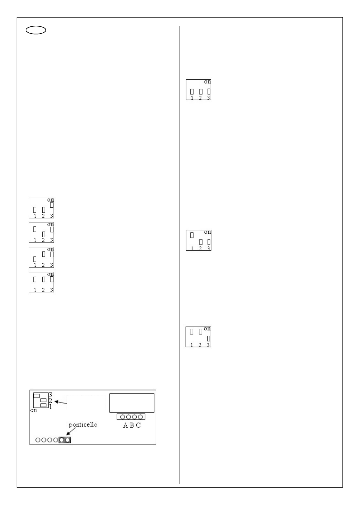
Programmazione della scheda elettronica
Collegare la scheda elettronica presente sulla piastra 6145/2T
o 6142/2T al BUS 2Fili utilizzando i morsetti B1 e B2.
Verificare che il led rosso della scheda si accenda con un
ritmo di impulsi regolari. Per programmare gli ID dei dispositivi
da associare alla scheda elettronica posizionare il dip-switch
numero 3 in “ON” (vedi disegno) e i dip-switch 1 e 2 a seconda del numero di ID (primo, secondo, terzo,quarto ID).
Durante la programmazione il led rosso della scheda inizia a
lampeggiare con un ritmo più veloce.
La programmazione può essere fatta in due modi o inviando
il codice di serratura da un dispositivo (citofono, videocitofono
o interfaccia 3532) o premendo sulla targa esterna il corrispondente pulsante di chiamata. L’acquisizione del codice di
programmazione viene segnalato da uno sfarfallio veloce del
led rosso sulla scheda stessa e dall’accensione per 2 secondi
del monitor.
Alla fine della programmazione riportare tutti i dip-switch in
“OFF”.
Effettuare una chiamata dalla targa esterna e verificare che il
monitor si accenda regolarmente.
Cancellazione degli ID programmati
Per cancellare tutti gli ID programmati :
1 - Togliere l’alimentazione staccando il bus 2 fili e l’eventuale
alimentazione data alla scheda dall’alimentatore supplementare 6923.
2 - Inserire un ponticello sui primi due contatti del connettore
come mostrato in figura e posizionare il dip-switch 3 in posizione “ON”.
Programmazione del primo ID (ID1)
Programmazione del secondo ID (ID2)
Programmazione del terzo ID (ID3)
Programmazione del quarto ID (ID4
)
Funzionamento principale:
tutti i dip-switch su OFF
3 - Collegare l’alimentazione (il bus 2 fili e l’eventuale alimentatore supplementare 6923). Il led rosso inizia a lampeggiare
velocemente.
4 - Togliere il ponticello e riportare il dip-switch 3 in posizione
“OFF”. Il led rosso inizia a lampeggiare più lentamente.
I
Funzionamento Principale
In funzionamento principale la scheda elettronica accende il
monitor ogni volta che da un posto esterno si esegue una
chiamata video ad un dispositivo dell’impianto due fili il cui ID
corrisponde ad uno dei quattro ID programmati nella scheda
elettronica.
Funzionamento secondario (vedi esempio 2)
In funzionamento secondario, la scheda elettronica associa il
monitor ad un dispositivo del bus due fili che è programmato
con ID secondario che fa parte di un gruppo di chiamata.
Bisogna quindi programmare l’ID1 della scheda elettronica
con l’ID principale del dispositivo e l’ID2 della scheda con l’ID
principale del capogruppo. Se il dispositivo associato alla
scheda elettronica è in gruppo con una seconda chiamata
corrispondente ad un secondo capogruppo, l’ID di quest’ultimo capogruppo va programmato sull’ID3 della scheda elettronica. Se il dispositivo associato alla scheda elettronica è in
gruppo con una terza chiamata corrispondente ad un terzo
capogruppo, l’ID di quest’ultimo capogruppo va programmato
sull’ID4 della scheda elettronica. Nel caso il dispositivo associato alla scheda elettronica sia in gruppo con un quarto
capogruppo, è necessario passare alla modalità di funzionamento IN GRUPPO.
Funzionamento in gruppo
In funzionamento in gruppo la scheda elettronica accende il
monitor ogni volta che da un posto esterno si esegue una
chiamata video ad un dispositivo dell’impianto due-fili il cui ID
corrisponde ad uno dei quattro ID programmati nella scheda
elettronica. Se si risponde da uno dei quattro ID programmati
nella scheda elettronica il monitor si spegne. Se si risponde
da un ID diverso dai quattro ID programmati nella scheda
elettronica il monitor rimane acceso.
Funzionamento secondario:
solo il dip-switch 1 va su ON
Funzionamento in gruppo:
I dip-switch 1 e 2 su ON
Dip-switch
con 3 su ON
Page 3

3
Esempio 1 (funzionamento principale)
Impianto a due fili con una sola interfaccia universale 3532,
con 4 telefoni 3562 e 4 monitor 6009 tutti sotto un unico centralino telefonico. Si vuole che dalla targa esterna con 4 pulsanti di chiamata ogni pulsante con il proprio indirizzo chiami
un telefono abbinato al corrispettivo monitor.
Programmare la 3532 nel seguente modo :
*#1234# 71 1 # 61 1 # 01 n. telefono # 72 2 # 62 2 #02 n.
telefono# 73 3 # 63 3 #03 n. telefono # 74 4# 64 4 # 04 n.
telefono #**
Programmare la scheda elettronica del 6145/2T o 6142/2T
che collega il telefono al singolo monitor nel seguente modo:
1- Posizionare il dip-swicth 3 della scheda in “ON”
2- Inviare dalla targa esterna la chiamata premendo il pul-
sante con l’indirizzo ID corrispondente, il led della schedina
deve effettuare uno sfarfallio veloce segno di programmazione recepita. Il monitor deve accendersi per un istante e poi
spegnersi.
3- Riportare il dip-switch 3 in posizione “OFF”.
La programmazione deve essere eseguita prendendo in considerazione un telefono con il corrispondente monitor alla
volta.
Esempio 2 (funzionamento secondario)
Impianto a due fili con interfaccia universale 3532, 1 telefono
3562 abbinato al 6009 e un 1 monitor 6309 con ID=3. Si vuole
che dalla targa esterna una chiamata faccia suonare sia il
monitor 6309 che il telefono con abbinato il monitor 6009.
Programmare la 3532 nel seguente modo :
*# 1234 # 71 7# 61 3 # 01 “n. telefono” #**
Programmare la scheda elettronica della 6145/2T o 6142/2T
nel seguente modo :
1- Posizionare il dip-swicth 3 della scheda in “ON” e i dipswitch 1 e 2 su OFF.
2- Inviare dall’interfaccia 3532 un comando di serratura:
- chiamare da un telefono l’interfaccia telefonica e attendere la risposta
- digitare i tasti *1
- riagganciare il telefono
I led della scheda elettronica deve effettuare uno sfarfallio
veloce come segno di programmazione recepita. Il monitor deve accendersi per un istante e poi spegnersi.
3- Posizionare i dip-switch 1 e 3 su ON e il dip-switch 2 su
OFF (per programmare l’ID2).
4- Eseguire una chiamata dal posto esterno al monitor 6309
(ID=3). Il led della scheda elettronica deve effettuare uno
sfarfallio veloce come segno di programmazione recepita. Il
monitor deve accendersi per un istante e poi spegnersi.
5- Riportare il dip-switch 1 in ON e i dip-switch 2-3 in OFF
(funzionamento secondario).
GB
Description
Items 6142/2T and 6145/2T are respectively a desktop base
and a wall-mounting bracket. Both items use a circuit board
which enables the activation of a Petrarca monitor type 6009
(6009/C).
Programming the circuit board
Connect the circuit board on plate 6145/2T or 6142/2T to the
2-WIRE BUS using terminals B1 and B2. Check that the red
LED on the circuit board is pulsing at regular intervals. To program the IDs of the devices to be associated with the circuit
board, put dip-switch number 3 onto “ON” (see drawing) and
dip-switches 1 and 2 according to the ID number (first, second, third, fourth ID). During programming, the red LED on
the circuit board starts to flash more frequently.
Programming can be done in two ways, either by sending the
lock code from a device (such as an interphone, video door
entry unit or interface 3532) or by pressing the corresponding
call pushbutton on the external entrance panel. The red LED
on the circuit board will flicker rapidly and the monitor will
come on for 2 seconds to indicate that the programming code
has been acquired.
After programming, put all the dip-switches back onto “OFF”.
Make a call from the external entrance panel and check that
the monitor switches on automatically.
Deleting the programmed IDs
To delete all the programmed IDs:
1 - Cut off the power supply by disconnecting the 2-wire bus
and any supply provided to the circuit board by the supplementary power supply unit 6923.
2 - Insert a jumper on the first two contacts of the connector
as shown in the figure and put dip-switch 3 onto “ON”.
Programming the first ID (ID1)
Programming the second ID (ID2)
Programming the third ID (ID3)
Programming the fourth ID (ID4)
3 - Connect the power supply (the 2-wire bus and any supplementary power supply unit 6923). The red LED starts to blink
quickly.
4 - Remove the jumper and put dip-switch 3 back onto “OFF”.
The red LED starts to blink more slowly.
Dip-switch
with 3 ON
Jumper
Page 4
4
Main operation:
all the dip-switches OFF
Main Operation
In main operation the electronic card switches on the monitor
each time a video call is made from a speech unit to a device
in the 2-wire system whose ID corresponds to one of the four
IDs programmed on the circuit board.
Secondary operation (see example 2)
In secondary operation, the circuit board associates the monitor with a device of the 2-wire bus that is programmed with a
secondary ID that belongs to a call group. It is therefore
necessary to program ID1 of the circuit board with the main ID
of the device and ID2 of the circuit board with the main ID of
the group master. If the device associated with the circuit
board is in the same group as a second call corresponding to
a second group master, the ID of the latter group master must
be programmed on ID3 of the circuit board. If the device associated with the circuit board is in the same group as a third
call corresponding to a third group master, the ID of the latter
group master must be programmed on ID4 of the circuit
board. If the device associated with the circuit board is in the
same group as a fourth group master, it is necessary to go
into the GROUP operating mode.
Group operation
In group operation the circuit board switches on the monitor
each time a video call is made from a speech unit to a device
in the 2-wire system whose ID corresponds to one of the four
IDs programmed on the circuit board. If answering from one
of the four IDs programmed on the circuit board the monitor
will switch off. If answering from a different ID to the four IDs
programmed on the circuit board the monitor will stay on.
Secondary operation:
only dip-switch 1 goes onto ON
Group operation:
Dip-switches 1 and 2 ON
Example 1 (main operation)
2-wire system with a single universal interface 3532, with 4
phones 3562 and 4 monitors 6009 all under a single telephone switchboard. From the entrance panel with 4 call buttons
you want each button with its own address to call a phone
associated with the corresponding monitor.
Program 3532 as follows:
*#1234# 71 1 # 61 1 # 01 no. phone # 72 2 # 62 2 #02 no.
phone # 73 3 # 63 3 #03 no. phone # 74 4# 64 4 # 04 no.
phone #**
Program the circuit board of 6145/2T or 6142/2T connecting
the phone to the single monitor as follows:
1- Set dip-switch 3 of the circuit board to “ON”
2- Send the call from the entrance panel by pressing the
button with the corresponding ID, the LED on the card must
blink quickly, signalling that the programming has been
received. The monitor must switch on for a moment and
then switch off.
3- Move dip-switch 3 back onto “OFF”.
Programming must be performed by taking into consideration
one phone with its corresponding monitor at a time.
Example 2 (secondary operation)
2-wire system with a single universal interface 3532, 1 phone
3562 associated with 6009 and one 1 monitor 6309 with ID=3.
From the entrance panel you want a call to ring both the
monitor 6309 and the phone associated with the monitor
6009.
Program 3532 as follows:
*# 1234 # 71 7# 61 3 # 01 “no. phone ” #**
Program the circuit board of 6145/2T or 6142/2T as follows:
1- Set dip-switch 3 of the circuit board to “ON” and dip-
switches 1 and 2 to OFF.
2- Send a lock command from the interface 3532:
- call the telephone interface from a phone and wait for the
answer
- key in buttons *1
- hang up the phone
The LED on the circuit board must blink quickly, signalling
that the programming has been received. The monitor
must switch on for a moment and then switch off.
3- Set dip-switches 1 and 3 to ON and dip-switch 2 to OFF
(to program ID2).
4- Make a call from the speech unit to the monitor 6309
(ID=3). The LED on the circuit board must blink quickly,
signalling that the programming has been received. The
monitor must switch on for a moment and then switch off.
5- Put dip-switch 1 back onto ON and dip-switches 2-3
onto OFF (secondary operation).
Page 5
5
F
Description
Les articles 6142/2T et 6145/2T sont respectivement une
base de table et un étrier de fixation murale. Les deux articles
utilisent une carte électronique qui permet l’activation d’un
poste Petrarca Art. 6009 (6009/C).
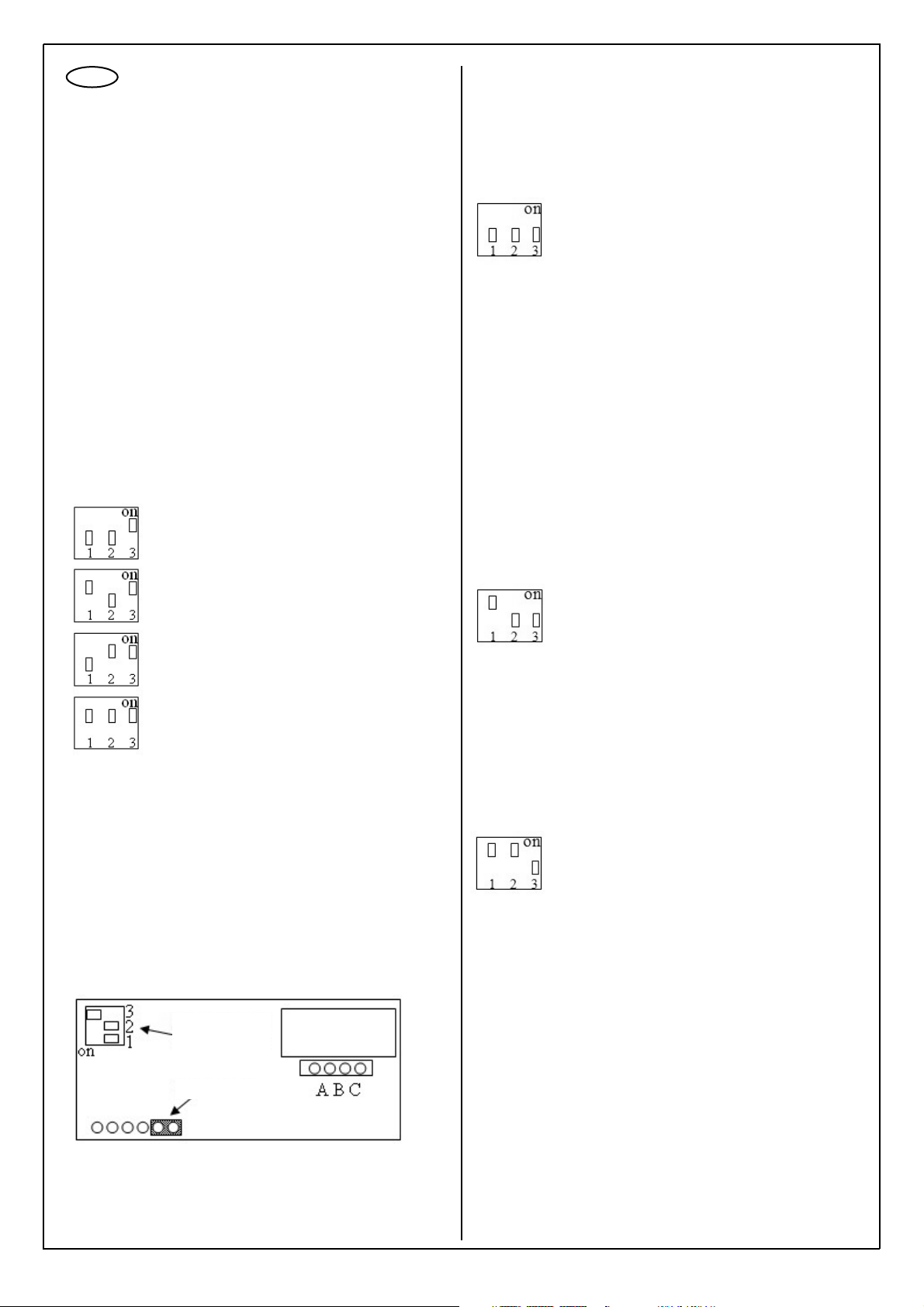
Programmation de la carte électronique
Relier la carte électronique présente sur la plaque 6145/2T ou
6142/2T au BUS 2Fils en utilisant les bornes B1 et B2.
Vérifier que la led rouge de la carte s’allume et clignote de
manière régulière. Pour programmer les codes ID des dispositifs à associer à la carte électronique, positionner le dip-switch numéro 3 sur “ON” (voir dessin) et les dip-switches 1 et 2
selon le nombre d’ID (premier, second, troisième, quatrième
ID). Durant la programmation, la led rouge de la carte commence à clignoter plus rapidement.
La programmation peut être effectuée de deux manières : soit
en envoyant le code de gâche depuis un dispositif (interphone, visiophone ou interface 3532) soit en appuyant sur la platine de rue sur le bouton correspondant d’appel. L’acquisition
du code de programmation est signalée par le clignotement
rapide de la led rouge sur la carte et par l’allumage du moniteur pendant 2 secondes.
À la fin de la programmation, remettre tous les dip-switches
sur “OFF”.
Effectuer un appel depuis la platine de rue et vérifier si le
moniteur s’allume normalement.
Effacement des ID programmés
Pour effacer tous les ID programmés :
1 - Couper l’alimentation en détachant le bus 2 fils et l’éventuelle alimentation fournie à la carte par l’alimentateur supplémentaire 6923.
2 - Insérer un pontet sur les deux premiers contacts du
connecteur comme le montre la figure et positionner le dipswitch 3 sur “ON”.
Programmation du premier ID (ID1)
Programmation du second ID (ID2)
Programmation du troisième ID (ID3)
Programmation du quatrième ID (ID4)
Fonctionnement principal :
tous les dip-switches sur OFF
3 - Relier l’alimentation (le bus 2 fils et l’éventuel alimentateur
supplémentaire 6923). La led rouge commence à clignoter
rapidement.
4 - Enlever le pontet et remettre le dip-switch 3 sur “OFF”. La
led rouge commence à clignoter plus lentement.
Fonctionnement Principal
En fonctionnement principal, la carte électronique allume le
moniteur chaque fois que l’on effectue un appel vidéo à un
dispositif de l’installation Deux fils depuis une platine de rue,
dont l’ID correspond à l’un des quatre ID programmés dans la
carte électronique.
Fonctionnement secondaire (voir exemple 2)
En fonctionnement secondaire, la carte électronique associe
le moniteur à un dispositif du bus Deux fils qui est programmé
avec ID secondaire faisant partie d’un groupe d’appel. Il faut
donc programmer l’ID de la carte électronique avec l’ID principal du dispositif et l’ID2 de la carte avec l’ID principal du chef
de groupe. Si le dispositif associé à la carte électronique est
en groupe avec un second appel correspondant à un second
chef de groupe, l’ID de ce dernier chef de groupe doit être
programmé sur l’ID 3 de la carte électronique. Si le dispositif
associé à la carte électronique est en groupe avec un troisième appel correspondant à un troisième chef de groupe, l’ID
de ce dernier chef de groupe doit être programmé sur l’ID 4
de la carte électronique. Si le dispositif associé à la carte
électronique est en groupe avec un quatrième chef de groupe, il est nécessaire de passer au mode de fonctionnement
EN GROUPE.
Fonctionnement en groupe
En fonctionnement en groupe, la carte électronique allume le
moniteur chaque fois que l’on effectue un appel vidéo à un
dispositif de l’installation Deux fils depuis une platine de rue,
dont l’ID correspond à l’un des quatre ID programmés dans la
carte électronique. Si on répond depuis l’un des quatre ID
programmés dans la carte électronique, le moniteur s’éteint.
Si on répond depuis un ID différent des quatre ID programmés dans la carte électronique, le moniteur reste allumé.
Fonctionnement secondaire :
uniquement le dip-switch 1 va sur ON
Fonctionnement en groupe :
I dip-switches 1 et 2 sur ON
Dip-switch
avec 3 sur ON
Pontet
Page 6
6
D
Exemple 1 (fonctionnement principal)
Installation à deux fils avec une seule interface universelle
3532, avec 4 téléphones 3562 et 4 moniteurs 6009 tous sous
un unique standard téléphonique. On veut que, depuis la platine de rue avec 4 boutons d’appel, chaque bouton avec la
propre adresse appelle un téléphone associé au moniteur
correspondant.
Programmer la 3532 de la manière suivante :
*#1234# 71 1 # 61 1 # 01 n. téléphone # 72 2 # 62 2 #02 n.
téléphone# 73 3 # 63 3 #03 n. téléphone # 74 4# 64 4 # 04
n. téléphone #**
Programmer la carte électronique de 6145/2T ou 6142/2T qui
relie le téléphone au moniteur de la manière suivante :
1- Positionner le dip-switch 3 de la carte sur “ON”
2- Depuis la platine de rue, envoyer l’appel en appuyant
sur le bouton avec l’adresse ID correspondante ; la led de
la carte doit clignoter rapidement pour indiquer qu’elle
reçoit la programmation. Le moniteur doit s’allumer pendant un instant puis s’éteindre.
3- Remettre le dip-switch 3 en position “OFF”.
La programmation doit être effectuée en prenant en considération un téléphone à la fois avec son moniteur correspondant.
Exemple 2 (fonctionnement secondaire)
Installation à deux fils avec interface universelle 3532, 1
téléphone 3562 associé au 6009 et 1 moniteur 6309 avec
ID=3. On veut que, depuis la platine de rue, un appel fasse
sonner tant le moniteur 6309 que le téléphone avec le moniteur 6009 associé.
Programmer l’interface 3532 de la manière suivante :
*# 1234 # 71 7# 61 3 # 01 “n. téléphone” #**
Programmer la carte électronique de la 6145/2T ou 6142/2T
de la manière suivante :
1- Positionner le dip-switch 3 de la carte sur “ON” et les
dip-switches 1 et 2 sur OFF.
2- Envoyer depuis l’interface 3532 une commande de
gâche :
- appeler depuis un téléphone l’interface téléphonique et
attendre la réponse
- taper les touches *1
- raccrocher
La led de la carte électronique doit clignoter rapidement
pour indiquer qu’elle reçoit la programmation. Le moniteur
doit s’allumer pendant un instant puis s’éteindre.
3- Positionner les dip-switches 1 et 3 sur ON et le dip-swit-
ch 2 sur OFF (pour programmer l’ID2).
4- Effectuer un appel depuis la platine de rue au moniteur
6309 (ID=3). La led de la carte électronique doit clignoter
rapidement pour indiquer qu’elle reçoit la programmation.
Le moniteur doit s’allumer pendant un instant puis s’étein-
dre.
5- Remettre le dip-switch 1 sur ON et les dip-switches 2-3
sur OFF (fonctionnement secondaire).
Beschreibung
Bei den Artikeln 6142/2T und 6145/2T handelt es sich respektive um eine Tischbasis bzw. eine Wandhalterung. Beide
Artikel enthalten eine Elektronikplatine, die zur Aktivierung
eines Monitors Petrarca Art. 6009 (6009/C) dient.
Programmierung der Elektronikplatine
Die Elektronikplatine der Platte 6145/2T bzw. 6142/2T mit den
Klemmen B1 und B2 am BUS 2 FILI anschließen.
Kontrollieren, ob die rote Led der Platine mit regelmäßigen
Impulsen aufleuchtet. Zur Programmierung der ID-Codes der
Geräte, die der Elektronikplatine zugeordnet werden sollen,
den Dip-Schalter Nr. 3 auf “ON” setzen (siehe Zeichnung) und
die Dip-Schalter 1 und 2 je nach ID-Code einstellen (erster,
zweiter, dritter, vierter ID-Code). Während der
Programmierung beginnt die rote Led der Platine schneller zu
blinken.
Die Programmierung erfolgt entweder durch Senden des
Türschlosscodes von einem Gerät (Haustelefon,
Videohaustelefon oder Schnittstelle 3532) oder durch
Drücken der entsprechenden Ruftaste am Klingeltableau. Die
Erfassung des Programmierungscodes wird durch ein schnelles Flackern der roten Led an der Platine und durch ein
2sekündiges Einschalten des Monitors angezeigt.
Am Ende der Programmierung alle Dip-Schalter auf “OFF”
stellen.
Einen Türruf vornehmen und kontrollieren, ob der Monitor
ordnungsgemäß einschaltet.
Löschen der programmierten ID-Codes
Zum Löschen aller ID-Codes folgendermaßen vorgehen:
1 - Die Stromzufuhr durch Trennen des 2-Draht-Busses und
die eventuelle Versorgung zur Platine des Zusatz-Netzgeräts
6923 trennen.
2 - An den ersten zwei Kontakten des Steckverbinders eine
Steckbrücke einsetzen wie auf der Abbildung dargestellt und
den Dip-Schalter 3 auf “ON” setzen.
Programmierung des ersten ID-Codes (ID1)
Programmierung des zweiten ID-Codes (ID2)
Programmierung des dritten ID-Codes (ID3)
Programmierung des vierten ID-Codes (ID4)
3 - Die Stromversorgung anschließen (2-Draht-Bus und evtl.
Zusatznetzgerät 6923). Die rote Led beginnt, schnell zu
blinken.
4 - Die Steckbrücke herausnehmen und Dip-Schalter 3 wieder
auf “OFF” setzen. Die rote Led beginnt, langsamer zu blinken.
3. Dip-Schalter
auf ON
Steckbrücke
Page 7

7
Hauptbetrieb:
alle Dip-Schalter auf OFF
Hauptbetrieb
Im Hauptbetrieb schaltet die Platine jedes Mal, wenn von
einer Türsprechstelle ein Videoruf an ein Gerät der 2-DrahtAnlage getätigt wird, dessen ID-Code einem der vier in der
Elektronikplatine programmierten ID-Codes entspricht, den
Monitor ein.
Sekundärbetrieb (siehe Beispiel 2)
Im Sekundärbetrieb ordnet die Elektronikplatine den Monitor
einem Gerät des 2-Draht-Busses zu, das mit einem
Nebencode programmiert ist, der zu einer Rufgruppe gehört.
Also muss die ID1 der Elektronikplatine mit der Haupt-ID des
Geräts, und die ID2 der Elektronikplatine mit der Haupt-ID
des Hauptgeräts programmiert werden. Wenn das der
Elektronikplatine zugewiesene Gerät zu einer Gruppe gehört,
in der ein zweiter Ruf einem zweiten Hauptgerät entspricht,
wird die ID des Letzteren an der ID3 der Elektronikplatine programmiert. Wenn das der Elektronikplatine zugewiesene
Gerät zu einer Gruppe gehört, in der ein dritter Ruf einem dritten Hauptgerät entspricht, wird die ID des Letzteren an der
ID4 der Elektronikplatine programmiert. Wenn das der
Elektronikplatine zugewiesene Gerät zu einer Gruppe mit
einem vierten Hauptgerät gehört, muss auf GRUPPENBETRIEB gewechselt werden.
Gruppenbetrieb
Im Gruppenbetrieb schaltet die Platine jedes Mal, wenn von
einer Türsprechstelle ein Videoruf an ein Gerät der 2-DrahtAnlage getätigt wird, dessen ID-Code einem der vier in der
Elektronikplatine programmierten ID-Codes entspricht, den
Monitor ein. Wenn von einem der vier in der Elektronikplatine
programmierten ID-Codes geantwortet wird, geht der Monitor
aus. Wenn von einem anderen als die vier in der
Elektronikplatine programmierten ID-Codes geantwortet wird,
bleibt der Monitor an.
Beispiel 1 (Hauptbetrieb)
Zweidrahtanlage mit nur einer Universal-Schnittstelle 3532,
mit 4 Telefonen 3562 und 4 Monitoren 6009, alle unter einer
einzigen Telefonzentrale. Es soll erreicht werden, dass von
der Türstation mit 4 Ruftasten jeder Taster mit der eigenen
Adresse ein Telefon anruft, das dem jeweiligen Monitor
zugeordnet ist.
Die Schnittstelle 3532 folgendermaßen programmieren:
*#1234# 71 1 # 61 1 # 01 Nr. Telefon # 72 2 # 62 2 #02 Nr.
Telefon# 73 3 # 63 3 #03 Nr. Telefon # 74 4# 64 4 # 04 Nr.
Telefon #**
Die Elektronikplatine des Art. 6145/2T oder 6142/2T, der das
Telefon mit dem einzelnen Monitor verbindet, folgendermaßen
programmieren:
1- Den Dip-Schalter 3 der Platine auf “ON” setzen
2- Von der Türstation durch Drücken der Taste mit der entsprechenden ID-Adresse den Ruf tätigen. Die Erfassung der
Programmierung wird durch ein schnelles Flackern der Led
an der Platine angezeigt. Der Monitor muss für einen
Augenblick ein- und dann ausschalten.
3- Den Dip-Schalter 3 wieder auf “OFF” setzen.
Bei Programmierung muss jeweils ein Telefon mit dem dazugehörenden Monitor berücksichtigt werden.
Beispiel 2 (Sekundärbetrieb)
Zweidrahtanlage mit Universal-Schnittstelle 3532, 1 Telefon
3562 mit 6009 und 1 Monitor 6309 mit ID=3. Es soll erreicht
werden, dass bei einem Anruf sowohl der Monitor 6309 als
auch das mit dem Monitor 6009 kombinierte Telefon läutet.
Die Schnittstelle 3532 folgendermaßen programmieren:
*# 1234 # 71 7# 61 3 # 01 “Nr. Telefon” #**
Die Elektronikplatine des Art. 6145/2T oder 6142/2T folgendermaßen programmieren:
1- Den Dip-Schalter 3 der Platine auf “ON”, und die Dip-
Schalter 1 und 2 auf OFF setzen.
2- Von der Schnittstelle 3532 einen Türöffnerbefehl ertei-
len:
- Von einem Telefon die Telefonschnittstelle anrufen und
auf Antwort warten
- Die Tasten *1 drücken
- Telefonhörer wieder auflegen
Die Erfassung der Programmierung wird durch ein
schnelles Flackern der Led an der Elektronikplatine angezeigt. Der Monitor muss für einen Augenblick ein- und
dann ausschalten.
3- Die Dip-Schalter 1 und 3 auf ON, und den Dip-Schalter
2 auf OFF setzen (für die Programmierung von ID2).
4- Den Monitor 6309 (ID=3) von der Türsprechstelle anru-
fen. Die Erfassung der Programmierung wird durch ein
schnelles Flackern der Led an der Elektronikplatine angezeigt. Der Monitor muss für einen Augenblick ein- und
dann ausschalten.
5- Den Dip-Schalter 1 auf ON und die Dip-Schalter 2-3 auf
OFF setzen(Sekundärbetrieb).
Sekundärbetrieb:
nur Dip-Schalter 1 auf ON
Gruppenbetrieb:
Dip-Schalter 1 und 2 auf ON
Page 8

8
E
Descripción
Los artículos 6142/2T y 6145/2T son, respectivamente, una
base de sobremesa y un soporte de fijación a la pared.
Ambos artículos utilizan una tarjeta electrónica que permite la
activación de un monitor Petrarca art. 6009 (6009/C).
Programación de la tarjeta electrónica
Conecte la tarjeta electrónica en la placa 6145/2T o 6142/2T
al BUS 2Fili de dos hilos utilizando los bornes B1 y B2.
Compruebe que el led rojo de la tarjeta se encienda con
impulsos regulares. Para programar los ID de los equipos a
asociar a la tarjeta electrónica, coloque el dip-switch número
3 en “ON” (véase el dibujo) y los dip-switches 1 y 2 según el
número di ID (primero, segundo, tercero y cuarto ID). Durante
la programación el led rojo de la tarjeta empieza a parpadear
con un ritmo más rápido.
La programación se puede realizar enviando el código del
abrepuertas desde un dispositivo (portero automático, videoportero o interfaz 3532) o bien pulsando en la placa externa
el pulsador de llamada correspondiente. La captación del
código de programación se señaliza con un rápido parpadeo
del led rojo en la tarjeta y el encendido durante 2 segundos
del monitor.
Al final de la programación, vuelva a colocar todos los dipswitches en “OFF”.
Realice una llamada desde la placa externa y compruebe que
el monitor se encienda correctamente.
Borrado de los ID programados
Para borrar todos los ID programados:
1 - Desconecte la alimentación desconectando el bus de 2
hilos y la alimentación posiblemente suministrada a la tarjeta
por el alimentador adicional 6923.
2 - Introduzca un puente en los dos primeros contactos del
conector según se muestra en la figura y coloque el dipswitch 3 en “ON”.
Programación del primer ID (ID1)
Programación del segundo ID (ID2)
Programación del tercer ID (ID3)
Programación del cuarto ID (ID4)
Funcionamiento principal:
todos los dip-switches en OFF
3 - Conecte la alimentación (el bus 2 hilos y el posible alimentador adicional 6923). El led rojo empieza a parpadear rápidamente.
4 - Retire el puente y vuelva a colocar el dip-switch 3 en
“OFF”. El led rojo empieza a parpadear más lentamente.
Funcionamiento principal
En el modo de funcionamiento principal, la tarjeta electrónica
enciende el monitor cada vez que desde un aparato externo
se realiza una llamada vídeo a un dispositivo de la instalación
de dos hilos cuyo ID corresponde a uno de los cuatro ID programados en la tarjeta electrónica.
Funcionamiento secundario (véase el ejemplo 2)
En el modo de funcionamiento secundario, la tarjeta electrónica asocia el monitor a un dispositivo del bus dos hilos que
está programado con el ID secundario que forma parte de un
grupo de llamada. Luego hay que programar el ID1 de la
tarjeta electrónica con el ID principal del dispositivo y el ID2
de la tarjeta con el ID principal del elemento principal del
grupo. Si el dispositivo asociado a la tarjeta electrónica está
en el grupo con una segunda llamada correspondiente a un
segundo elemento principal del grupo, el ID de este último se
debe programar en el ID3 de la tarjeta electrónica. Si el dispositivo asociado a la tarjeta electrónica está en el grupo con
una tercera llamada correspondiente a un tercer elemento
principal del grupo, el ID de este último se debe programar en
el ID4 de la tarjeta electrónica. Si el dispositivo asociado a la
tarjeta electrónica está en el grupo con un cuarto elemento
principal del grupo, es necesario pasar al modo de funcionamiento EN GRUPO.
Funcionamiento en grupo
En el modo de funcionamiento en grupo, la tarjeta electrónica
enciende el monitor cada vez que desde un aparato externo
se realiza una llamada vídeo a un dispositivo de la instalación
de dos hilos cuyo ID corresponde a uno de los cuatro ID programados en la tarjeta electrónica. Si se contesta desde uno
de los cuatro ID programados en la tarjeta electrónica, el
monitor se apaga. Si se contesta desde un ID distinto a los
cuatro ID programados en la tarjeta electrónica, el monitor
permanece encendido.
Funcionamiento secundario:
sólo el dip-switch 1 está en ON
Funcionamiento secundario:
sólo el dip-switch 1 está en ON
Dip-switch con
3 en ON
Puente
Page 9

9
P
Ejemplo 1 (funcionamiento principal)
Instalación de dos hilos con una única interfaz universal
3532, con 4 teléfonos 3562 y 4 monitores 6009 todos controlados por una única centralita telefónica. El objetivo es que,
desde la placa externa con 4 pulsadores de llamada, cada
pulsador con su propia dirección llame un teléfono asociado
al monitor correspondiente.
Programe la 3532 según se indica a continuación:
*#1234# 71 1 # 61 1 # 01 n. teléfono # 72 2 # 62 2 #02 n.
teléfono# 73 3 # 63 3 #03 n. teléfono # 74 4# 64 4 # 04 n.
teléfono #**
Programe la tarjeta electrónica del 6145/2T o 6142/2T que
conecta el teléfono al monitor según se indica a continuación:
1- Coloque el dip-switch 3 de la tarjeta en “ON”
2- Envíe desde la placa externa la llamada apretando el
pulsador con la dirección ID correspondiente, el led de la
tarjeta debe parpadear rápidamente, lo que indica que la
programación es efectiva. El monitor debe encenderse
durante un instante y luego apagarse.
3- Vuelva a colocar el dip-switch 3 en “OFF”.
La programación se debe realizar cada vez en un teléfono
con su correspondiente monitor.
Ejemplo 2 (funcionamiento secundario)
Instalación de dos hilos con interfaz universal 3532, 1 teléfono 3562 asociado al 6009 y un 1 monitor 6309 con ID=3. El
objetivo es que, desde la placa externa, una llamada haga
sonar el timbre del monitor 6309 así como el teléfono que
lleva asociado el monitor 6009.
Programe la 3532 según se indica a continuación:
*# 1234 # 71 7# 61 3 # 01 “n. teléfono” #**
Programe la tarjeta electrónica de la 6145/2T o 6142/2T
según se indica a continuación:
1- Coloque el dip-switch 3 de la tarjeta en “ON” y los dipswitch 1 y 2 en OFF.
2- Envíe desde la interfaz 3532 un mando de cerradura:
- llame desde un teléfono la interfaz telefónica y espere la
respuesta
- pulse las teclas *1
- cuelgue el teléfono
El led de la tarjeta electrónica debe parpadear rápidamente, lo que indica que la programación es efectiva. El monitor debe encenderse durante un instante y luego apagarse.
3- Coloque los dip-switch 1 y 3 en ON y el dip-switch 2 en
OFF (para programar el ID2).
4- Realice una llamada desde el aparato externo al monitor
6309 (ID=3). El led de la tarjeta electrónica debe parpadear rápidamente, lo que indica que la programación es
efectiva. El monitor debe encenderse durante un instante y
luego apagarse.
5- Vuelva a colocar el dip-switch 1 en ON y los dip-switch
2-3 en OFF (funcionamiento secundario).
Descrição
Os artigos 6142/2T e 6145/2T são respectivamente uma base
de mesa e um suporte de fixação à parede. Ambos os artigos
utilizam uma placa electrónica que permite a activação de um
monitor Petrarca art. 6009 (6009/C).
Programação da placa electrónica
Ligue a placa electrónica presente no suporte 6145/2T ou
6142/2T ao BUS 2 Fili utilizando os bornes B1 e B2.
Certifique-se de que o led vermelho da placa se acende com
um ritmo de impulsos regulares. Para programar os ID dos
dispositivos a associar à placa electrónica coloque o dipswitch número 3 na posição “ON” (ver desenho) e os dipswitch 1 e 2 consoante o número de ID (primeiro, segundo,
terceiro, quarto ID). Durante a programação o led vermelho
da placa começa a piscar com um ritmo mais rápido.
A programação pode ser feita em dois modos: ou enviando o
código de trinco a partir de um dispositivo (telefone, monitor
ou interface 3532) ou premindo, na botoneira externa, o
botão de chamada correspondente. A aquisição do código de
programação é assinalada por uma intermitência rápida do
led vermelho na própria placa e pelo acendimento do monitor
durante 2 segundos.
No fim da programação coloque novamente todos os dipswitch na posição “OFF”.
Faça uma chamada a partir da botoneira externa e certifiquese de que o monitor se liga normalmente.
Eliminação dos ID programados
Para apagar todos os ID programados:
1 - Desligue a alimentação retirando o Bus 2 Fili e a eventual
alimentação dada à placa pelo alimentador suplementar
6923.
2 - Insira uma ponte nos primeiros dois contactos do conector
conforme mostrado na figura e coloque o dip-switch 3 na
posição “ON”.
Programação do primeiro ID (ID1)
Programação do segundo ID (ID2)
Programação do terceiro ID (ID3)
Programação do quarto ID (ID4)
3 - Ligue a alimentação (o Bus 2 Fili e o eventual alimentador
suplementar 6923). O led vermelho começa a piscar
rapidamente.
4 - Retire a ponte e coloque novamente o dip-switch 3 na
posição “OFF”. O led vermelho começa a piscar mais
lentamente.
Dip-switch
com 3 em ON
Ponte
Page 10

10
Funcionamento principal:
todos os dip-switch em OFF
Funcionamento principal
No funcionamento principal a placa electrónica liga o monitor
sempre que, a partir de um posto externo, se faz uma
chamada vídeo para um dispositivo do sistema Due Fili cujo
ID corresponda a um dos quatro ID programados na placa
electrónica.
Funcionamento secundário (ver o exemplo 2)
No funcionamento secundário, a placa electrónica associa o
monitor a um dispositivo do Bus Due Fili que está programado com um ID secundário que faz parte de um grupo de chamada. É, assim, preciso programar o ID1 da placa electrónica
com o ID principal do dispositivo e o ID2 da placa com o ID
principal do dispositivo “principal do grupo”. Se o dispositivo
associado à placa electrónica estiver em grupo com uma
segunda chamada correspondente a um segundo dispositivo
“principal do grupo”, o ID deste último “principal do grupo”
deve ser programado no ID3 da placa electrónica. Se o
dispositivo associado à placa electrónica estiver em grupo
com uma terceira chamada correspondente a um terceiro
“principal do grupo”, o ID deste último “principal do grupo”
deve ser programado no ID4 da placa electrónica. Caso o
dispositivo associado à placa electrónica esteja em grupo
com um quarto “principal do grupo”, é necessário passar ao
modo de funcionamento EM GRUPO.
Funcionamento em grupo
No funcionamento em grupo a placa electrónica liga o monitor sempre que, a partir de um posto externo, se faz uma chamada vídeo para um dispositivo do sistema Due Fili cujo ID
corresponda a um dos quatro ID programados na placa electrónica. Se se responder a partir de um dos quatro ID programados na placa electrónica, o monitor desliga-se. Se se
responder a partir de um ID distinto dos quatro ID programados na placa electrónica, o monitor mantém-se ligado.
Exemplo 1 (funcionamento principal)
Sistema Due Fili com uma única interface universal 3532,
com 4 telefones 3562 e 4 monitores 6009 todos sob uma
única central telefónica. Pretende-se que, a partir da botoneira externa com 4 botões de chamada, cada botão com o próprio endereço chame um telefone associado ao respectivo
monitor.
Programe a 3532 da seguinte forma:
*#1234# 71 1 # 61 1 # 01 n. telefone # 72 2 # 62 2 #02 n.
telefone # 73 3 # 63 3 #03 n. telefone # 74 4# 64 4 # 04 n.
telefone #**
Programe a placa electrónica do 6145/2T ou 6142/2T que liga
o telefone ao monitor individual da seguinte forma:
1- Coloque o dip-switch 3 da placa na posição “ON”
2- Envie a chamada a partir da botoneira externa premindo
o botão com o endereço ID correspondente; o led da placa
deve emitir um sinal intermitente rápido, sinal de que a programação foi recebida. O monitor deve ligar-se por um
instante e, depois, desligar-se.
3- Coloque novamente o dip-switch 3 na posição “OFF”.
A programação deve ser feita levando em consideração um
telefone com o monitor correspondente de cada vez.
Exemplo 2 (funcionamento secundário)
Sistema Due Fili com interface universal 3532, 1 telefone
3562 associado ao 6009 e um 1 monitor 6309 com ID=3.
Pretende-se que, a partir da botoneira externa, uma chamada
faça soar quer o monitor 6309, quer o telefone com o monitor
6009 associado.
Programe a 3532 da seguinte forma:
*# 1234 # 71 7# 61 3 # 01 “n. telefone” #**
Programe a placa electrónica da 6145/2T ou 6142/2T da
seguinte forma:
1- Coloque o dip-switch 3 da placa na posição “ON” e os
dip-switch 1 e 2 na posição OFF.
2- Envie a partir da interface 3532 um comando de trinco:
- a partir de um telefone, faça uma chamada para a interface telefónica e aguarde a resposta
- prima as teclas *1
- desligue o telefone
O led da placa electrónica deve emitir um sinal intermitente
rápido como sinal de que a programação foi recebida. O
monitor deve ligar-se por um instante e, depois, desligarse.
3- Coloque os dip-switch 1 e 3 na posição ON e o dip-swit-
ch 2 na posição OFF (para programar o ID2).
4- Faça uma chamada a partir do posto externo para o
monitor 6309 (ID=3). O led da placa electrónica deve emitir
um sinal intermitente rápido como sinal de que a programação foi recebida. O monitor deve ligar-se por um instante e, depois, desligar-se.
5- Coloque novamente o dip-switch 1 na posição ON e o
dip-switch 2-3 na posição OFF (funcionamento secundário).
Funcionamento secundário:
apenas o dip-switch 1 é posto em ON
Funcionamento em grupo:
Os dip-switch 1 e 2 em ON
Page 11

11
Dip-Switch (vedi Programmazione), Dipswitches (see Programming)
Dip-Switch (voir Programmation), Dip-Schalter (siehe Programmierung)
Microinterruptor (ver
Programación), Dip-Switch (ver Programação)
Scheda elettronica - Electronic board
Carte électronique - Steckkarte
Tarjeta electrónica - Placa electrónica
Terminazione video (vedi terminazione bus per impianti due fili Elvox)
Video termination (see bus termination for Elvox Due Fili installations)
Terminaison vidéo (voir terminaison bus pour installations deux fils Elvox)
Video-Abschluss (siehe Bus-Abschluss für Zweidrahtanlagen Elvox)
Terminación vídeo (ver terminación bus para instalaciones dos hilos Elvox)
Terminação vídeo (ver terminação bus para instalações dois fios Elvox)
Collegamento
Connection
Raccordement
Anschluss
Conexión
Ligação
Art. 6009
(Art. 6009/C)
B1
B2
+
-
Linea bus - Bus line
Ligne bus - Busleitung
Línea bus - Linha bus
Alimentatore supplementare
Additional power supply
Alimentation supplémentaire
Zusatznetzgerät
Alimentador suplementario
Alimentador suplementar
Art. 6923
Page 12

12
Art. 6145/2T con scatola da incasso a 3 moduli
Art. 6145/2T with 3-module flush-mounting back box
Art. 6145/2T avec boîtier à encastrer à 3 modules
Art. 6145/2T mit 3-Modul-Unterputzgehäuse
Art. 6145/2T con caja de empotrar de 3 módulos
Art. 6145/2T com caixa de embeber 3 módulos
Art. 6145/2T con scatola da incasso Art. 7149
Art. 6145/2T with flush-mounting back box Art. 7149
Art. 6145/2T avec boîtier à encastrer Art. 7149
Art. 6145/2T mit Unterputzgehäuse Art. 7149
Art. 6145/2T con caja de empotrar Art. 7149
Art. 6145/2T com caixa de embeber Art. 7149
Page 13

13
Art. 6142/2T
Inserimento connettore monitor 6009
(6009/C) sulla scheda elettronica.
Inserção do conector monitor 6009
(6009/C) na placa electrónica.
Insertion connector of monitor 6009
(6009/C) in the electronic circuit board
Insertion du connecteur du moniteur
6009 (6009/C) dans la carte électronique.
Einsetzung des Verbinders des Monitors
6009 (6009/C) in der Elektronikkarte
Inserción del conector del monitor 6009
(6009/C) en la ficha electrónica.
Morsetti
kit art. 6142/2T
Terminals
kit art. 6142/2T
Bornes
kit art. 6142/2T
Klemmen
kit art. 6142/2T
Regleta
kit art. 6142/2T
Tomada
kit art. 6142/2T
Corrispondenza colore conduttori
Correspondence of conductor colour
Correspondence des couleurs des conducteurs
Überstimmung der Leiterfarben
Correspondencia colores conductores
Correspondencia colores conductores
Morsetti sulla scheda elettronica
SCH.311.200 del KIT Art. 6142/2T.
Terninals in the electronic circuit board
SCH.311.200 of KIT Art. 6142/2T.
Bornes dans la carte électronique
SCH.311.200 du KIT Art. 6142/2T.
Klemmen in der Elektronikkarte
SCH.311.200 des KIT Art. 6142/2T.
Regleta na placa electrónica
SCH.311.200 do KIT Art. 6142/2T.
Tomada en la ficha electrónica
SCH.311.200 del KIT Art. 6142/2T.
1
Azzurro-Sky blue-Bleu ciel-Hellblau-Azul claro
N.U.
2
Bianco-White-Blanc-Weiss-Blanco-Branco
N.U.
3
Rosa-Pink-Rose-Rosa
N.U.
4
Arancio-Orange-Naranja-Laranja
+ (Art. 6923)
5
Blu sez.-Blue sect.-Bleu sect.- Blau Querschnitt - Azul sec. 0,5mm
B1
6
Rosso sez.-Red sect.-Rouge Sect-Rot querschnitt-Rojo sec. 0,5mm
B2
7
Nero-Black-Noir-Schwarz-Negro-Preto
- (Art. 6923)
8
Giallo-Yellow-Jaune-Gelb-Amarillo-Amarelo
N.U.
9
Marrone-Brown-Marron-Braun-Marron-Castanho
N.U.
10
Verde-Green-Vert-Grün-Verde
N.U.
11
Viola-Purple-Violet-Violett-Violeta
N.U.
12
Bianco/Verde-White/Green-Blanc/Vert-Weiß/Grün-
Blanco/Verde-
Branco/Verde
N.U.
V1-V2
Anima coassiale-Cable core-Âme du câble coaxial-Koaxialer KernMalla coaxial-Alma coaxial
N.U.
M1-M2
Schermo-Shield-Blindage-Schirm-Pantalla-Trança
N.U.
PREDISPOSIZIONE KIT Art. 6142/2T PER IMPIANTI DUE FILI ELVOX
KIT Art. 6142/2T CONFIGURATION FOR INSTALLATIONS TWO ELVOX WIRES
VORRÜSTUNG DES KIT Art. 6142/2T FÜR ANLAGEN ZWEI ELVOX DRÄHTE
PRÉDISPOSITION DUKIT Art. 6142/2T POUR INSTALLATIONS DEUX FILS ELVOX
PREDISPOSICIÓN KIT Art. 6142/2T PARA INSTALACIONES DOS HILOS ELVOX
PREPARAÇÃO DO MONITOR PARA INSTALAÇÕES DOIS FIOS ELVOX
N.U. = Non utilizzato - Not used - Non utilisé - Unbenutzt - No se utiliza - Não utilizado
Page 14

14
IMPIANTI CON DISTRIBUTORE PASSIVO 692D.
TABELLE FÜR DEN BUSVERSCHLUSS IN ELVOX DUE FILI-ANLAGEN
ANLAGEN MIT PASSIVVERTEILER 692D
INSTALLATIONS AVEC DISTRIBUTEUR PASSIF 692D
TERMINAISON BUS POUR INSTALLATIONS DEUX FILS ELVOX
INSTALLATIONS WITH PASSIVE DISTRIBUTOR 692D
BUS TERMINATION TABLE FOR ELVOX TWO WIRE SYSTEMS
TERMINAZIONE BUS PER IMPIANTI DUE FILI ELVOX
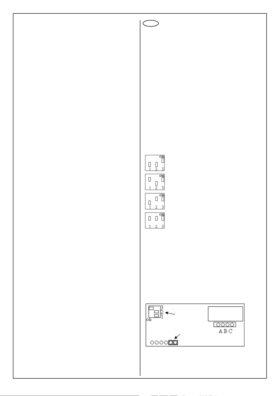
Per ogni dispositivo collegato all’art. 692D:
1. sul connettore ABC di qualsiasi articolo collegato ad una delle uscite 1, 2, 3,
4 dell’art. 692D, IL PONTICELLO VA MANTENUTO IN POSIZIONE “A”;
2. sul connettore ABC di qualsiasi articolo collegato all’uscita OUT del 692D, IL
PONTICELLO VA INSERITO IN POSIZIONE “B” OPPURE “C”.
Per la terminazione dell’art. 692D
3. Se l’uscita OUT del 692D non viene utilizzata, MANTENERE IL PONTICELLO SUL CONNETTORE “A” DEL 692D.
4. Se l’uscita OUT del 692D viene utilizzata, TOGLIERE IL PONTICELLO DAL
CONNETTORE “A” DEL 692D.
In alcune versioni dell’art. 692D sono presenti anche i connettori a pettine “B”,
“C” e “D”. In tal caso NON INSERIRE MAI NESSUN PONTICELLO SU DI ESSI
IMPIANTI CON DISTRIBUTORE ATTIVO 692D/1 e 692D/2
In questi articoli l’ingresso e l’uscita del BUS sono rappresentati dalle coppie di
morsetti 1-2, 1-2 (1-2, B1-B2 nel 692D/1). Il ponticello va posizionato su “B” (o
su ”C”) SE E SOLO SE tali morsetti non vengono utilizzati per proseguire il BUS
(non è collegato nessun dispositivo per la terminazione della linea).
Questa nota si applica a tutti i dispositivi in tecnologia DUE FILI ELVOX dotati del
“connettore di terminazione BUS”, identificato sulla scheda elettronica dalla scritta
serigrafica “ABC” e segnalata sugli schemi di collegamento con * . Su questo connettore va inserito un ponticello al fine di poter adattare il segnale video.
La regola da seguire per un corretto adattamento di linea è:
•
mantenere il ponticello in posizione “A” se il BUS entra ed esce dal dispositivo;
• mantenere il ponticello in posizione “A” se il dispositivo è collegato ad un
distributore art. 692D, 692D/1 o 692D/2;
•
spostare, nell’ultimo dispositivo, il ponticello in posizione “B”, nei seguenti casi:
- la linea del BUS “termina” nel dispositivo stesso (ultimo dispositivo in
configurazione entra ed esce);
- il segnale video dei dispositivi collegati ai distributori art. 692D/1 o 692D/2
non è soddisfacente;
• se la resa in “B” non è del tutto soddisfacente, provare la posizione “C”.
“A” NESSUNA TERMINAZIONE
“B” TERMINAZIONE 100 Ohm
“C” TERMINAZIONE 50 Ohm
(*) Nelle schede che riportano la serigrafia “ABCD” al posto di “ABC”, considerare le seguenti corrispondenze A = AB; B = BC; C = CD.
This note is applied to all devices with DUE FILI ELVOX (two wire Elvox) technology equipped with the “BUS termination connector”, identified on the electronic
card with the “ABC” serigraph and signalled on the wiring diagrams with a “*”.
For a correct video signal adjustment put the jumper on strip socket connector.
Follow next rule for the correct line adjustment:
• keep the jumper in “A” position when the BUS line “pass through” the device;
• keep the jumper in “A” position if the device is connected to a distributor
type 692D, 692D/1 or 692D/2
•
displace, in the last device, the jumper into “B” position in the following cases:
- the “BUS” line “ends within ” the same device (the last device in configuration “pass through”
- the video signal of the connected distributors type 692D/1 or 692D/2 is
not good.
• if the video signal adjustment is not good with jumper in “B” position, try
“C” position.
“A” NO TERMINATION
“B” TERMINATION 100 Ohm
“C” TERMINATION 50 Ohm
(*) On circuit boards supporting the “ABCD” serigraph instead of “ABC”, consider the following correspondences: A = AB; B = BC; C = CD.
For each device connected to type 692D:
1. on connector ABC in any article connected to one of the outputs 1, 2, 3, 4
of type 692D, THE JUMPER MUST BE KEPT IN POSITION “A”;
2. on connector ABC in any article connected to output OUT of type 692D,
THE JUMPER MUST BE INSERTED IN “B” OR “C” POSITION.
For termination of type 692D:
3. If output OUT of type 692D is not used, KEEP THE JUMPER ON CONNECTOR “A” OF TYPE 692D.
4. If output OUT of type 692D is used, REMOVE THE JUMPER FROM
CONNECTOR “A” OF TYPE 692D.
In some versions of type 692D there are also the strip socket connectors “B”,
“C” and “D”. In this case NEVER INSERT AJUMPER IN THEM.
INSTALLATIONS WITH ACTIVE DISTRIBUTOR 692D/1 and 692D/2
(
**
) In this articles the BUS input and output are terminals (1-2, B1-B2, in
type 692D/2). The jumper is to be set on “B” (or on “C”). IF AND ONLY IF
these terminals are not used to go on with the BUS (there is no device connected for the line termination).
Cette note s’applique a tous les dispositifs avec technologie DUE FILI ELVOX
(deux fils elvox) fournis du « connecteur de terminaison BUS », identifié sur la
carte électronique par la sérigraphie « ABC », signalisée sur les schémas de
raccordement avec « * ».
Sur ce connecteur on insère un pontage afin d’adapter le signal vidéo. La règle
à suivre pour une adaptation correcte de la ligne est la suivante :
• maintenir le pontage en position « A » si le BUS entre et sort du dispositif ;
• maintenir le pontage en position « A » si le dispositif est raccordé à un distributeur Art. 692D, 692D/1 ou 692D/2 ;
• déplacer, dans le dernier dispositif, le pontage sur la position « B » dans les
cas suivants :
- la ligne du BUS « termine » sur le même dispositif (dernier dispositif en
configuration « entre et sort ») :
- le signal vidéo des dispositifs raccordés aux distributeurs Art. 692D/1 ou
692D/2 n’est pas satisfaisant ;
• si le rendement en « B » n’est pas totalement satisfaisant, essayer la position « C ».
“A” AUCUNE TERMINAISON
“B” TERMINAISON 100 Ohm
“C” terminaison 50 Ohm
(*) Sur les cartes portant la sérigraphie “ABCD” à la place de “ABC”, considérer
les correspondances suivantes A = AB; B = BC; C = CD.
Dieser Hinweis wird bei allen Geräten mit DUE FILI ELVOX (Elvox 2-Draht)Technologie angewendet, die mit dem Bus-Verschlussverbinder ausgestattet
sind, der auf der Platine mit dem „ABC“-Serigraph gekennzeichnet ist, der
auf der Schaltpläne mit „*“ dargestellt ist. An diesem Verbinder wird eine
Steckbrücke eingesetzt, um das Videosignal anpassen zu können.
Für eine korrekte Linienanpassung muss die Folgende Regel eingehalten werden:
• die Steckbrücke in Position „A“ lassen, wenn der BUS in das Gerät einund wieder austritt;
• die Steckbrücke auf Position „A“ lassen, wenn die Vorrichtung am
Verteiler Art. 692D, 692D/1 oder 692D/2 angeschlossen ist;
• Die Steckbrücke (bei der letzten Vorrichtung) auf Position „B“ setzen in
folgenden Fällen:
- die Buslinie im Gerät „endet“ (letzte Vorrichtung in „ein- und wieder
austritt“- Konfiguration)
- das Videosignal der an Verteiler Art. 692D/1 oder 692D/2 angeschlossenen Vorrichtungen nicht zufrieden ist;
• Wenn die erbrachte Leistung auf Position „B“ nicht zufrieden stellend ist,
die Position „C“ ausprobieren.
„A“ KEIN ENDVERSCHLUSS
„B“ ENDVERSCHLUSS 100 Ohm
„C“ ENDVERSCHLUSS 50 Ohm
(*) Bei den Platinen mit dem Aufdruck “ABCD” anstellevon “ABC” sind die folgenden Übereinstimmungen zubeachten A= AB; B = BC; C = CD.
Pour chaque dispositif relié à l’art. 692D :
1.
sur le connecteur ABC de n'importe quel article relié à l'une des sorties 1, 2, 3, 4
de l’art. 692D, LE PONTET DOIT ETRE MAINTENU EN POSITION “A” ;
2. sur le connecteur ABC de n'importe quel article relié à la sortie OUT du
692D, LE PONTET DOIT ETRE INSERE EN POSITION “B” OU “C”.
Pour la terminaison de l’art. 692D
3. Si la sortie OUT du 692D n'est pas utilisée, MANTENIR LE PONTET SUR
LE CONNECTEUR “A” DU 692D.
4. Si la sortie OUT du 692D est utilisée, OTER LE PONTET DU CONNECTEUR “A” DU 692D.
Dans certaines versions de l'art. 692D, les connecteurs à peigne “B”, “C” et “D”
sont également présents. Dans ce cas, NE JAMAIS INSERER DE PONTETS
SUR CES DERNIERS.
INSTALLATIONS AVEC DISTRIBUTEUR ACTIVE 692D/1 et 692D/2
Dans cet article, l'entrée et la sortie du BUS sont les bornes 1-2, 1-2 (1-2, B1B2, dans 692D/2). Le pontet doit être positionné sur “B” (ou sur ”C”). SI ET SEULEMENT SI ces bornes ne sont pas utilisées pour continuer le BUS (aucun
dispositif est raccordé pour la terminaison de la ligne).
Für jedes am Art. 692D angeschlossene Gerät:
1. Am Verbinder ABC jedes beliebigen Gerätes, das an einem der
Ausgänge 1, 2, 3, 4 des Art. 692D angeschlossen ist, MUSS DIE
STECKBRÜCKE IN POSITION “A” GELASSEN WERDEN;
2. Am Verbinder ABC jedes beliebigen Gerätes, das am Ausgang OUT des
Art. 692D angeschlossen ist, MUSS DIE STECKBRÜCKE IN POSITION
“B” ODER “C” EINGESETZT WERDEN.
Für den Abschluss des Art. 692D:
3. Wenn der Ausgang OUT des Art. 692D nicht benutzt wird, DIE
STECKBRÜCKE AM VERBINDER “A” DES ART. 692D LASSEN.
4. Wenn der Ausgang OUT des Art. 692D benutzt wird, DIE
STECKBRÜCKE VOM VERBINDER “A” DES ART. 692D ENTFERNEN.
Bei einigen Versionen des Art. 692D sind auch die Kammverbinder “B”, “C” und
“D” vorhanden. In diesem Fall NIEMALS EINE STECKBRÜCKE DARAN EINSETZEN.
INSTALLATIONS AVEC DISTRIBUTEUR ACTIVE 692D/1 et 692D/2
Dans cet article, l'entrée et la sortie du BUS sont les bornes 1-2, 1-2 (1-2,
B1-B2, dans 692D/2). Le pontet doit être positionné sur “B” (ou sur ”C”). SI
ET SEULEMENT SI ces bornes ne sont pas utilisées pour continuer le BUS
(aucun dispositif est raccordé pour la terminaison de la ligne).
Page 15

15
Sezione conduttori - Conductor section
Sections des conducteurs-Leiterqueschnitt
Secciones conductores-Secção condutores
Morsetti-Terminals Ø fino a 10m-Ø up to 10m Ø fino a 50m-Ø up to 50m Ø fino a 100m-Ø up to 100m Ø fino a 150m-Ø up to 150m
Bornes-Klemmen Ø jusqu’à 10m-Ø bis 10m Ø jusqu’à 50m.-Ø bis 50m Ø jusqu’à 100m-Ø bis 100m Ø jusqu’à 150m.-Ø bis 150m
Bornes-Terminais Øhasta 10m - até 10m Ø hasta 50m - até 50m Øhasta 100m - até 100m Ø hasta 150m - até 150m
1, 2, B1, B2 0,5 mm
2
0,5 mm
2
0,75 mm
2
1 mm
2
Cavo -Cable
Câble - Kabel Art. 732H Art. 732H Art. 732H Art. 732H
Cable - Cabo
Serratura elettrica
Electric lock
Gâche électrique 1,5 mm
2
-- -
Elektrisches Türschloss
Cerradura eléctrica
Trinco eléctrico
INSTALACIONES CON DISTRIBUIDOR PASIVO 692D
TERMINACIÓN BUS PARA INSTALACIONES DE DOS HILOS ELVOX
INSTALAÇÕES COM DISTRIBUIDOR PASSIVO 692D
TERMINAÇÃO BUS PARA INSTALAÇOES DE DOIS FIOS ELVOX
Esta nota aplica-se a todos os dispositivos com tecnología DUE FILI
ELVOX (dois fios elvox) dotados do “conector de terminação BUS”, identificado na placa electrónica pela serigrafía “ABC” e sinalada nos esquemas
de ligação com (*). Neste conector é inserida uma ponte para poder adaptar o sinal de vídeo.
A regra a seguir para obter uma adaptação correcta da linha é a seguinte:
• manter a ponte na posição “A” se o BUS entra e sai do dispositivo;
• manter a ponte na posição “A” se o dispositivo è ligado a um distribuidor
Art. 692D, 692D/1 ou 692D/2;
• deslocar, no último dispositivo, a ponte em posição “B” nos casos
seguintes:
- a linha do BUS termina no referido dispositivo (último dispositivo em
configuraçãlo “entra e sai”);
- o sinal video dos dispositivos ligados aos distribuidores Art. 692D/1 ou
692D/2 não é satisfactorio;
• se o rendimento em “B” não è totalmente satisfactório, colocar a ponte
na posição “C”.
“A” NENHUMA RESISTENCIA
“B” RESISTENCIA DE FECHO DE 100 Ohm
“C” RESISTENCIA DE FECHO DE 50 Ohm
(*) Nas placas que tem a serigrafía “ABCD” em lugar de “ABC”, considerar
as seguintes correspondências:A = AB; B = BC; C = CD.
Esta nota se aplica a todos los dispositivos con tecnologia DUE FILI ELVOX
(dos hilos elvox) dotados del “conector de terminación BUS”, identificado en
la ficha electrónica por la serigrafía “ABC”, indicada en los esquemas de
conexionado con “*”. En este conector se instala un puente para adaptar la
señal de vídeo.
Para una correcta adaptación de la línea seguir la norma que sigue:
• mantener el puente en la posición “A » si el BUS entra y sale del dispositivo;
• mantener el puente en la posición “A” si el dispositivo está conectado a
un distribuidor Art. 692D, 692D/1 o 692D/2.
• Desplazar, en el último dispositivo, el puente en posición “B” en los
siguientes csos:
- la línea del BUS “termina” en elmismo dispositivo (último dispositivo en
configuración entra y sale)
- la señal vídeo de los dispositivos conectados a los distribuidores Art. 692D/1
o 692D/2 no es satisfactoria;
• si el rendimiento en “B” no es completamente satisfactorio, probar la posición “C”
“A” NINGUNA TERMINACIÓN
“B” TERMINACIÓN 100 Ohm
“C” TERMINACIÓN 50 Ohm
(
*) En las tarjetas con la serigrafía “ABCD” en lugar de “ABC”, hay que tener
en cuenta las siguientes correspondencias A = AB, B = BC y C = CD.
Por cada dispositivo ligado ao Art. 692D:
1. no conector ABC de qualquer artigo ligado a uma das saídas 1, 2, 3, 4
do Art. 692D, A PONTE DEVE SER MANTIDA NA POSIÇÃO “A”;
2. no conector ABC de qualquer artigo ligado à saída OUT do Art. 692D,
A PONTE DEVE SER INSERIDA NA POSIÇÃO “B” OU “C”.
Para a terminação do Art. 692D
3. Se a saída OUT do Art. 692D não é utilizada , MANTER A PONTE NO
CONECTOR “A” do Art. 692D.
4. Se a saída OUT do Art. 692D é utilizada, RETIRAR A PONTE DO
CONECTOR “A” DO Art. 692D.
Nalgumas versões do Art. 692D são presentes também os conectores
“tipo pente” “B”, “C” e “D”. Neste caso NÃO INSERIR NUNCA QUALQUER PONTE SOBRE ELES
INSTALAÇÕES COM DISTRIBUIDOR ACTIVO 692D/1 E 692D/2
Neste artigo a entrada e a saída do BUS são os terminais 1-2, 1-2 (1-2, B1-B2,
no Art. 692D/2). A ponte deve ser colocada em “B” (ou em “C”).
SE E SÓ SE
estes terminais não são ligados para prosseguir o BUS (nenhum dispositivo é ligado para a terminação da linha).
Para cada dispositivo conectado al art. 692D:
1. en el conector ABC de cualquier artículo conectado a una de las salidas 1,
2, 3 y 4 del art. 692D, EL PUENTE TIENE QUE MANTENERSE EN LA
POSICIÓN “A”;
2. en el conector ABC de cualquier artículo conectado a la salida OUT del
692D, EL PUENTE TIENE QUE PONERSE EN LA POSICIÓN “B” O LA
“C”.
Para la terminación del art. 692D
3. Si la salida OUT del 692D no se utiliza, MANTENER EL PUENTE EN EL
CONECTOR “A” DEL 692D.
4. Si la salida OUT del 692D se utiliza, QUITAR EL PUENTE DEL CONECTOR “A” DEL 692D.
En algunas versiones del art. 692D también están los conectores de backplane “B”, “C” y “D”. En dicho caso NO INTRODUCIR NUNCA NINGÚN PUENTE EN ELLOS.
INSTALACIONES CON DISTRIBUIDOR ACTIVO 692D/1 Y 692D/2
En este artículo, la entrada y la salida del BUS son los bornes 1-2, 1-2 (1-2,
B1-B2, en el Art. 692D/2). El puente se tiene que colocar en “B” (o en ”C”).
SI
Y SOLAMENTE SI estos bornes no vienen utilizados para proseguir el BUS
(ningún dispositivo está conectado para la terminación de la línea).
Page 16

16
IMPIANTO VIDEOCITOFONICO CON INTERFACCIA TELEFONICA ART. 3532, CENTRALINO TELEFONICO, TELEFONI ART.
3562 IN ABBINAMENTO CON MONITOR ART. 6009, 6009/C MEDIANTE PIASTRA ART. 6145/2T O BASE ART. 6142/2T
VIDEO ENTRY INSTALLATION WITH TELEPHONE INTERFACE ART. 3532, TELEPHONE SWITCHBOARD, TELEPHONES ART.
3562 IN CONJUNCTION WITH MONITORS ART.
6009, 6009/C
BY MEANS OF PLATE ART. 6145/2T OR BASE ART. 6142/2T
INSTALLATION PORTIER VIDÉO AVEC INTERFACE TÉLÉPHONIQUE ART. 3532, STANDARD TÉLÉPHONIQUE, TÉLÉPHONES
ART. 3562 EN ASSOCIATION AVEC MONITEUR ART. 6009, 6009/C PAR PLAQUE ART. 6145/2T OU BASE ART. 6142/2T
VIDEOSPRECHANLAGE MIT TELEFONSCHNITTSTELLE ART. 3532, TELEFONZENTRALE, TELEFONEN ART. 3562 IN
KOMBINATION MIT MONITOR ART.
6009, 6009/C
MIT PLATTE ART. 6145/2T ODER TISCHSTÄNDER ART. 6142/2T
Montante - Cable riser
Colonne montante-Steigleitung
Coluna montante
Linea urbana
External line
Ligne externe
Externleitung
Línea externa
Linha urbana
Centralino telefonico
Telephone switchboard
Standard téléphonique
Telefonzentrale
Centralita telefónica
Central telefónica
Art. 35M8
Interfaccia telefonica
Telephone interface
Telefonschnittstelle
Interface téléphonique
Interfaz telefónica
Interface telefónico
Art. 3532
Linea telefonica o derivato di un
centralino telefonico
Telephone line or telephone switchboard extension line
Ligne téléphonique ou dérivation
d'un standard téléphonique
Telefonleitung oder Nebenstelle
einer Telefonzentrale
Línea telefónica o aparato derivado de una centralita telefónica
Linha telefónica ou posto de uma
central telefónica
Alimentatore - Power supply
Alimentation - Netzgerät
Alimentador Art. 352A
Alimentatore
Power supply
Alimentation
Netzgerät
Alimentador
Art. 6922
D- Targa video Art. 89F5/..., 89F5/C
D0- Targa video Art. 89F7/..., 89F7/C
L- Serratura elettrica 12V~
P- Comando apriporta
D- Botoneira vídeo Art. 89F5/..., 89F5/C
D0- Botoneira vídeo Art. 89F7/..., 89F7/C
L- Trinco eléctrico 12V~
P- Comando do trinco
Rete-Mains
Réseau-Netz
Red-Rede
Cavo
Cable
Câble
Kabel
Cabo
Art. 732H
D- Video entrance panel Art. 89F5/..., 89F5/C
D0- Video entrance panel Art. 89F7/..., 89F7/C
L- 12V~ electric lock
P- Door release control
Rete-Mains
Réseau-Netz
Red-Rede
D- Videotürstation Art. 89F5/..., 89F5/C
D0- Videotürstation Art. 89F7/..., 89F7/C
L- Elektroschloss 12V~
P- Türöffner
Cavo
Cable
Câble
Kabel
Cabo
Art. 732H
Cavo
Cable
Câble
Kabel
Cabo
Art. 732H
Cavo
Cable
Câble
Kabel
Cabo
Art. 732H
INSTALACIÓN DE VÍDEO-PORTEROS CON INTERFAZ TELEFÓNICA
ART. 3532, CENTRALITA TELEFÓNICA, TELÉFONOS ART. 3562 EN
COMBINACIÓN CON MONITOR ART.
6009, 6009/C
MEDIANTE PLACA
ART. 6145/2T O BASE ART. 6142/2T
INSTALAÇÃO DE VIDEOPORTEIRO COM INTERFACE TELEFÓNICO
ART. 3532, CENTRAL TELEFÓNICA, TELEFONES ART. 3562 EM
CONJUNTO COM MONITOR ART.
6009, 6009/C
ATRAVÉS DA PLACA
ART. 6145/2T OU BASE ART. 6142/2T
D- Plaque vidéo Art. 89F5/..., 89F5/C
D0- Plaque vidéo Art. 89F7/..., 89F7/C
L- Gâche électrique 12V~
P- Commande ouvre-porte
D- Placa vídeo Art. 89F5/..., 89F5/C
D0- Placa vídeo Art. 89F7/..., 89F7/C
L- Cerradura eléctrica 12V~
P- Mando de apertura de puerta
Monitor - Moniteur
Art. 6009+3562+6142/2T
Art. 6009+3562+6145/2T
Art. 6009/C+3562+6142/2T
Art. 6009/C+3562+6145/2T
B2
B1
EXT+
EXTVLED
X
M
88888888
1
2
4
5
8
7
0
R
PA
CA
D0
M
S+
S+12V
-L
3
6
*
9
C
SR
F2
F1
M
P
L
D
A
B
C
B1
R1R2R1R2 B2
PRI
B112B2
P
L
B2
B1
EXT+
EXTVLED
X
M
PA
CA
M
S+
S-
+12V
-L
SR
F2
F1
M
028V
-B
U4U6U5+B U3
A
B
C
VIDEO
48 4647 45 L2L14143 4244
PRI
2
1
B1
B2
+
-
Page 17

17
VARIANTE DI COLLEGAMENTO PER
ALIMENTATORE SUPPLEMENTARE
ART. 6923 A UN MONITOR ART.
6000, 6003 MEDIANTE PIASTRA
6145/2T O BASE 6142/2T
CONNECTION VARIANT FOR SUPPLEMENTARY POWER SUPPLY
UNIT ART. 6923 TO MONITOR ART.
6000, 6003 BY WAY OF PLATE
6145/2T OR BASE 6142/2T
ANSCHLUSSVARIANTE FÜR
ZUSATZNETZGERÄT ART. 6923 AN
EINEM MONITOR ART. 6000, 6003
MIT PLATTE 6145/2T ODER
TISCHSTÄNDER 6142/2T
VARIANTE DE RACCORDEMENT
POUR ALIMENTATION SUPPLÉMENTAIRE ART. 6923 À UN MONITEUR
ART. 6000, 6003 AU MOYEN DE PLAQUE 6145/2T OU BASE 6142/2T
VARIANTE DE CONEXIÓN PARA ALIMENTADOR SUPLEMENTARIO ART.
6923 A UN MONITOR ART. 6000,
6003 MEDIANTE PLACA 6145/2T O
BASE 6142/2T
VARIANTE DE LIGAÇÃO PARA ALIMENTADOR SUPLEMENTAR ART.
6923 COM UM MONITOR ART. 6000,
6003 ATRAVÉS DA PLACA 6145/2T
OU BASE 6142/2T
Monitor - Moniteur
Art. 6009+3562+6142/2T
Art. 6009+3562+6145/2T
Art. 6009/C+3562+6142/2T
Art. 6009/C+3562+6145/2T
Alimentatore
Power supply
Alimentation
Netzgerät
Alimentador
Art. 6923
Rete-Mains
Réseau-Netz
Red-Rede
VIDEO
B1
A
B2
B
C
+
-
PRI
+I
- +U
Page 18
18
AVVERTENZE PER L'INSTALLATORE
- Leggere attentamente le avvertenze contenute nel
presente documento in quanto forniscono importanti indicazioni riguardanti la sicurezza di installazione, d'uso e di manutenzione.
- Dopo aver tolto l'imballaggio assicurarsi dell'integrità dell'apparecchio. Gli elementi dell'imballaggio (sacchetti di plastica, polistirolo espanso, ecc.)
non devono essere lasciati alla portata dei bambini
in quanto potenziali fonti di pericolo. L'esecuzione
dell'impianto deve essere rispondente alle norme
CEI vigenti.
- È necessario prevedere a monte dell'alimentazione
un appropriato interruttore di tipo bipolare facilmente accessibile con separazione tra i contatti di
almeno 3mm.
-
Prima di collegare l'apparecchio accertarsi che i dati
di targa siano rispondenti a quelli della rete di distribuzione.
- Questo apparecchio dovrà essere destinato solo
all'uso per il quale è stato espressamente concepito, e cioè per sistemi di citofonia. Ogni altro uso è
da considerarsi improprio e quindi pericoloso. Il
costruttore non può essere considerato responsabile per eventuali danni derivanti da usi impropri,
erronei ed irragionevoli.
-
Prima di effettuare qualsiasi operazione di pulizia o di
manutenzione, disinserire l'apparecchio dalla rete di
alimentazione elettrica, spegnendo l'interruttore dell'impianto.
- In caso di guasto e/o di cattivo funzionamento dell'apparecchio, togliere l'alimentazione mediante l'interruttore e non manometterlo. Per l'eventuale riparazione rivolgersi solamente ad un centro di assistenza tecnica autorizzato dal costruttore. Il mancato rispetto di quanto sopra può compromettere la
sicurezza dell'apparecchio.
- Non ostruire le aperture o fessure di ventilazione o
di smaltimento calore e non esporre l’apparecchio
a stillicidio o spruzzi d’acqua.
- L'installatore deve assicurarsi che le informazioni
per l'utente siano presenti sugli apparecchi derivati.
-
Tutti gli apparecchi costituenti l'impianto devono
essere destinati esclusivamente all'uso per cui sono
stati concepiti.
- L’interruttore onnipolare deve essere facilmente
accessibile.
-
ATTENZIONE: per evitare di ferirsi, questo apparecchio deve essere assicurato alla parete secondo le
istruzioni di installazione.
- Questo documento dovrà sempre rimanere allegato
alla documentazione dell'impianto.
Direttiva 2002/96/CE (WEEE, RAEE).
Il simbolo del cestino barrato riportato sull’apparecchio indica che il prodotto, alla fine della propria vita
utile, dovendo essere trattato separatamente dai rifiuti
domestici, deve essere conferito in un centro di raccolta differenziata per apparecchiature elettriche ed
elettroniche oppure riconsegnato al rivenditore al
momento dell’acquisto di una nuova apparecchiatura
equivalente.
L’utente è responsabile del conferimento dell’apparecchio a fine vita alle appropriate strutture di raccolta.
L’adeguata raccolta differenziata per l’avvio successivo dell’apparecchio dismesso al riciclaggio, al trattamento e allo smaltimento ambientalmente compatibile
contribuisce ad evitare possibili effetti negativi sull’ambiente e sulla salute e favorisce il riciclo dei materiali di cui è composto il prodotto. Per informazioni più
dettagliate inerenti i sistemi di raccolta disponibili,
rivolgersi al servizio locale di smaltimento rifiuti, o al
negozio in cui è stato effettuato l’acquisto.
Rischi legati alle sostanze considerate pericolose
(WEEE).
Secondo la nuova Direttiva WEEE sostanze che da
tempo sono utilizzate comunemente su apparecchi
elettrici ed elettronici sono considerate sostanze pericolose per le persone e l’ambiente. L’adeguata raccolta differenziata per l’avvio successivo dell’apparecchio
dismesso al riciclaggio, al trattamento e allo smaltimento ambientalmente compatibile contribuisce ad
evitare possibili effetti negativi sull’ambiente e sulla
salute e favorisce il riciclo dei materiali di cui è composto il prodotto.
SAFETY INSTRUCTIONS FOR INSTALLERS
- Carefully read the instructions on this leaflet: they
give important information on the safety, use and
maintenance of the installation.
- After removing the packing, check the integrity of
the set. Packing components (plastic bags,
expanded polystyrene etc.) are dangerous for
children. Installation must be carried out according to national safety regulations.
- It is convenient to fit close to the supply voltage
source a proper bipolar type switch with 3 mm
separation (minimum) between contacts.
- Before connecting the set, ensure that the data
on the label correspond to those of the mains.
- Use this set only for the purposes designed,
i.e.for electric door-opener systems. Any other
use may be dangerous. The manufacturer is not
responsible for damage caused by improper,
erroneous or irrational use.
- Before cleaning or maintenance, disconnect the
set.
- In case of failure or faulty operation, disconnect
the set and do not open it.
- For repairs apply only to the technical assistance
centre authorized by the manufacturer.
- Safety may be compromised if these instructions
are disregarded.
- Do not obstruct opening of ventilation or heat exit
slots and do not expose the set to dripping or
sprinkling of water.
- Installers must ensure that manuals with the
above instructions are left on connected units
after installation, for users' information.
- All items must only be used for the purposes
designed.
- The ominipolar switch must be easily accessed.
WARNING: to avoid the possibility of hurting yourself, this unit must be fixed to the wall according to
the installation instructions.
- This leaflet must always be enclosed with the
equipment.
Directive 2002/96/EC (WEEE)
The crossed-out wheelie bin symbol marked on the
product indicates that at the end of its useful life, the
product must be handled separately from household
refuse and must therefore be assigned to a differentiated collection centre for electrical and electronic
equipment or returned to the dealer upon purchase
of a new, equivalent item of equipment.
The user is responsible for assigning the equipment,
at the end of its life, to the appropriate collection
facilities.
Suitable differentiated collection, for the purpose of
subsequent recycling of decommissioned equipment
and environmentally compatible treatment and
disposal, helps prevent potential negative effects on
health and the environment and promotes the recycling of the materials of which the product is made.
For further details regarding the collection systems
available, contact your local waste disposal service
or the shop from which the equipment was purchased.
Risks connected to substances considered as
dangerous (WEEE).
According to the WEEE Directive, substances since
long usually used on electric and electronic appliances are considered dangerous for people and the
environment. The adequate differentiated collection
for the subsequent dispatch of the appliance for the
recycling, treatment and dismantling (compatible
with the environment) help to avoid possible negative effects on the environment and health and promote the recycling of material with which the product
is compound.
I
GB
F
CONSEILS POUR L'INSTALLATEUR
- Lire attentivement les instructions contenues dans
ce document puisqu'elles fournissent d'importantes
indications concernant la sécurité pour l'installation,
l'emploi et la maintenance.
- Après avoir enlevé l'emballage s'assurer de l'intégrité de l'appareil. Les éléments de l'emballage
(sachets en plastique, polystyrène, etc.) ne doivent
pas être laissés à la portée des enfants, car ils peuvent être dangereux. L'exécution de l'installation
doit être conforme aux normes nationales.
- Il est nécessaire de prévoir près de la source d’alimentation un interrupteur approprié, type bipolaire,
avec une separation entre les contacts d’au moins
3mm.
- Avant de connecter l'appareil s'assurer que les données reportées sur l'étiquette soient les mêmes que
celles du réseau de distribution.
-
Cet appareil devra être destiné uniquement à l'emploi
pour lequel il a été expressément conçu, c'est-à-dire
pour l'alimentation des systèmes de portiers électriques. Tout autre emploi doit être considéré impropre
et donc dangereux. Le constructeur ne peut pas être
considéré responsable pour d'éventuels dommages
résultant de l'emploi impropre, erroné et
déraisonnable.
-
Avant d'effectuer n'importe quelle opération de nettoyage ou de maintenance, débrancher l'appareil du
réseau d'alimentation électrique, en éteignant l'interrupteur de l'installation.
- En cas de panne et/ou de mauvais fonctionnement
de l'appareil, enlever l'alimentation au moyen de
l'interrupteur et ne pas le modifier.
- Pour une éventuelle réparation s'adresser uniquement à un centre d'assistance technique autorisé
par le constructeur. Si on ne respecte pas les
instructions mentionnées ci-dessus on peut compromettre la sécurité de l'appareil.
- Ne pas obstruer les ouvertures et les fentes de ventilation ou de refroidissement et ne pas exposer
l’appareil à l’égout ou jet d’eau.
- L'installateur doit s'assurer que les renseignements
pour l'usager soient présents dans les appareils
connectés.
- Tous les appareils constituant l'installation doivent
être destinés exclusivement à l'emploi pour lequel
ils ont été conçus.
- L’interrupteur omnipolaire doit être d’accès aisé.
- ATTENTION: pour éviter de se blesser, cet appareil
doit être assuré au mur selon les instructions d’installation.
- Ce document devra être toujours joint avec l'appareillage.
Directive 2002/96/CE (WEEE, RAEE)
Le symbole de panier barré se trouvant sur l'appareil indique que le produit, à la fin de sa vie utile, doit être traité
séparément des autres déchets domestiques et remis à
un centre de collecte différencié pour appareils électriques et électroniques ou remis au revendeur au moment
de l'achat d'un nouvel appareil équivalent.
L’usager est responsable du traitement de l'appareil
en fin de vie et de sa remise aux structures de collecte
appropriées. La collecte différenciée pour le démarrage successif de l’appareil remis au recyclage, au traitement et à l'élimination écocompatibles contribue à
éviter les effets négatifs environnementaux et sur la
santé tout en favorisant le recyclage des matériaux
dont se compose le produit. Pour des informations
plus détaillées sur les systèmes de collecte disponibles, contacter le service local d'élimination des
déchets ou le magasin qui a vendu l'appareil.
Risques liés aux substances considérées dangéreuses (WEEE).
Selon la Directive WEEE, substances qui sont utilisées depuis long temps habituellement dans des
appareils électriques et électroniques sont considerées dangéreuses pour les personnes et l'environnement. La collecte sélective pour le transfert suivant
de l’équipement destiné au recyclage, au traitement et
a l’écoulement environnemental compatible contribue
à éviter possibles effets négatifs sur l’environnement
et sur la salue et favorise le recyclage des matériaux
dont le produit est composé.
Page 19

D
CONSEJOS PARA EL INSTALADOR
- Leer atentamente los consejos contenidos en el
presente documento en cuanto dan importantes
indicaciones concernientes la seguridad de la
instalación, del uso y de la manutención.
- Después de haber quitado el embalaje asegurarse
de la integridad del aparato.
- Los elementos del embalaje (bolsos de plástico
etc.) no tienen que ser dejados al alcance de los
niños en cuanto posibles fuentes de peligro.
La ejecución de la instalación, debe respetar las
normas en vigor.
- Es necesário instalar cerca la fuente de alimentación un interruptor apropiado, de tipo bipolar,
con una separación entre los contactos de al
menos 3mm.
- Antes de conectar el aparato asegurarse que los
datos de la placa sean iguales a los de la red de
distribución.
- Este aparato tendrá que ser destinado solamente
al uso para el cual fue expresamente concebido,
es decir para alimentación de sistemas de portero
eléctrico.
Los otros usos deben ser considerados impropios
y por lo tanto peligrosos.
El constructor no puede ser considerado responsable de eventuales daños causados por usos
impropios erróneos e irrazonables.
- Antes de efectuar cualquiera operación de limpieza
o de manutención, desconectar el aparato de la
red de alimentación eléctrica, apagando el interruptor de la instalación.
- En caso de daño y/o de malo funcionamiento del
aparato, quitar la alimentación por medio del interruptor y no manipularlo.
Para eventuales reparaciones recurrir solamente a
un centro de asistencia técnica autorizado por el
constructor. La falta de respeto a lo anteriormente
expuesto puede comprometer la seguridad del
aparato.
- No obstruir las aberturas o hendiduras de ventilación o de salida calor.
- El instalador debe asegurarse que las informaciones para el usuario sean presentes en los
aparatos derivados.
- Todos los aparatos que constituyen la instalación
deben ser destinados exclusivamente al uso para
el qual fueron concebidos.
- O interrruptor omnipolar deve ser fácilmente
acessível.
- ATTENCIÓN: Para evitar de herirse, este aparato
debe ser fijado a la pared según las instruciones de
instalación.
- Este documento tendrà que ser siempre adjuntado
al aparato.
Directiva 2002/96/CE (WEEE, RAEE)
El símbolo del cubo de basura tachado, presente en
el aparato, indica que éste, al final de su vida útil, no
debe desecharse junto con la basura doméstica sino
que debe llevarse a un punto de recogida diferenciada para aparatos eléctricos y electrónicos o entregarse al vendedor cuando se compre un aparato equivalente.
El usuario es responsable de entregar el aparato a
unpunto de recogida adecuado al final de su vida.La
recogida diferenciada de estos residuos facilita el
reci-claje del aparato y de sus componentes, permite
su trata-miento y eliminación de forma compatible con
el medioambiente y previene los efectos negativos en
la naturale-za y la salud de las personas. Si desea
obtener más infor-mación sobre los puntos de recogida, contacte con el ser-vicio local de recogida de
basura o con la tienda dondeadquirió el producto.
Riesgos conectados a sustancias consideradas
peligrosas (WEEE).
Según la Directiva WEEE, substancias que desde
tiempo son utilizadas conmunemente en aparatos
eléctricos ed electrónicos son consideradas substancias peligrosas para las personas y el ambiente. La
adecuada colección diferenciada para el siguiente
envio del aparato destinado al reciclaje , tratamiento y
eliminación ambientalmente compatible contribuye a
evitar posibles efectos negativos sobre el ambiente y
la salud y favorece el reciclo de los materiales que
componen el producto.
CUIDADOS A TER PELO INSTALADOR
- Ler atentamente as advertências contidas no presente documento que fornecem importantes indicações no que diz respeito à segurança da instalação, ao uso e à manutenção.
- Após retirar a embalagem, assegurar-se da integridade do aparelho. Todos os elementos da embalagem (sacos plásticos, esferovite, etc.) ñao devem
ser deixados ao alcance de crianças pois são
fontes potenciais de perigo. A execução da instalação deve respeitar a regulamentação vigente no
país.
- É necessàrio instalar, perto da fuente de alimentação, um interruptor apropriado, do tipo bipolar,
com uma separação minima de 3 mm entre os contactos.
- Antes de ligar o aparelho verificar se os dados da
placa estão de acordo com os da rede de distribuição.
- Este aparelho só deve ser destinado ao uso para o
qual foi expressamente concebido, isto é, para alimentação de porteiro eléctrico.
Qualquer outra utilização deve ser considerada
imprópria e por conseguinte perigosa. O construtor
não pode ser considerado responsável por eventuais danos provocados por usos impróprios, errados
e irracionáveis.
- Antes de efectuar qualquer operação de limpeza ou
de manutenção, desligar o aparelho da rede de alimentação eléctrica através do dispositivo instalado.
- No caso de dano e/ou mau funcionamento do aparelho, eliminar a alimentação da rede através do dispositivo de corte e mantê-lo desligado. Para uma
eventual reparação recorrer sòmente a um centro
de assistência técnica autorizado pelo construtor. O
não cumprimento de tudo quanto anteriormente se
disse pode comprometer a segurança do aparelho.
- Não obstruir as aberturas ou ranhuras de ventilação ou de dissipação de calor e não expor o aparelho ao estilicidio du pulverização de agua.
-
O instalador deve assegurar-se de que as informações para o utilizador estão presentes nos aparelhos.
- Todos os aparelhos que constituem a instalação
devem ser destinados exclusivamente ao uso para
o qual foram concebidos.
- El interruptor omnipolar ha de ser fá fácilmente
accesibile.
- ATENÇÃO: Para evitar ferir-se, este aparelho deve
ser fixado na parede de acordo com as instruções de
instalação.
-
Este documento deverá estar sempre junto ao aparelho.
Norma 2002/96/CE (WEEE, RAEE)
O símbolo do cêsto barrado referido no aparelho indica que o producto, no fim da sua vida útil, tendo que
ser tratado separadamente dos refugos domésticos,
deve ser entregado num centro de recolha diferenciada para aparelhagens eléctricas e electrónicas ou
reconsignado ao revendedor no momento de aquisição dum novo aparelho equivalente.
O utente é responsável de entregar o aparelho a um
pontode recolha adequado no fim da sua vida.
Arecolha diferen-ciada de estos resíduos facilita a
reciclagem do aparelhoe dos suos componentes, permite o suo tratamento e a eli-minação de forma compatível com o meio ambiente e pre-vem os efectos
negativos na natura e saude das pessoas.Se se pretender mais informações sob os puntos de recol-ha,
contacte o serviço local de recolha de refugos ou
onegócio onde adquiriu o producto.
Perigos referidos à substancias consideradas perigosas (WEEE).
Según a Directiva WEEE, subtáncias que desde há
tempo utilizam-se comunemente nos aparelhos eléctricos e eléctrónicos são consideradas substáncias perigosas para as pessoas e o ambiente. A dequada
colecção diferenciada para o envio seguinte da aparelhagem deixada de usar para a reciclagem, ao tratamento e à eliminação ambientalmente compatível contribui a evitar possíveis efectos negativos no ambiente
e na saude e favorece o reciclo dos materiais dos
quais o producto é composto.
PE
ANWEISUNGEN FÜR DEN INSTALLATEUR
- Diese Anweisungen genau lesen, da sie über die
Sicherheit beim Einbau, den Gebrauch und Pflege
informieren.
- Nach dem Auspacken die Unversehrtheit des
Geräts feststellen. Verpackungsteile (Plastiktüten,
etc.) sind gefährlich für Kinder.
Die Installation muss den nationalen Normen ent-
sprechen.
- Es ist notwendig bei der
Spannungsversorgungsquelle einen passenden
zweipoligen Schalter einzubauen, der mindestens
3 mm Abstand zwischen den Kontakten haben
muss.
- Vor dem Anschließen des Gerätes sich versichern, dass die Daten am Typenschild mit denen
des Leitungsnetzes übereinstimmen.
- Dieses Gerät nur für den vorbestimmten
Gebrauch verwenden, d.h. für Türsprechanlagen.
Jeder andere Gebrauch ist gefährlich. Der
Hersteller nimmt keine Verantwortung für beim
Missbrauch des Gerätes entstandene Schäden.
- Vor jeglicher Säuberung oder Nachpflege das
Gerät vom Versorgungsnetz trennen.
- Im Falle einer Beschädigung und/oder falschen
Funktion des Geräts, dieses vom
Versorgungsnetz trennen und das Gerät nicht öffnen.
- Für eine eventuelle Reparatur wenden Sie sich an
eine offizielle technische Kundenbetreuungsstelle.
- Die Missachtung dieser Hinweise könnte Ihre
Sicherheit gefährden.
- Die Lüftungsschlitze des Gerätes nicht abdecken
und das Gerät keiner Feuchtigkeit oder Nässe
aussetzen.
- Der Installateur muss nach dem Einbau darauf
achten, dass diese Hinweise zur
Benutzerinformation immer bei den Geräten
vorhanden sind.
- Alle Geräte dürfen nur für den vorbestimmten
Gebrauch verwendet werden.
- Der zweipolige Schalter muss leicht zugänglich
sein.
- VORSICHT: um eine Verletzung zu vermeiden,
dieses Gerät an der Wand, wie in der
Installationsanleitung beschrieben, montieren.
- Dieses Blatt muss den Geräten immer beigelegt
werden.
Richtlinie 2002/96/EG (WEEE)
Das am Gerät angebrachte Symbol des durchgestrichenen Abfallkorbs bedeutet, dass das Produkt am
Ende seiner Lebenszeit vom Hausmüll getrennt zu
entsorgen ist, und einer Müllsammelstelle für
Elektro- und Elektronik-Altgeräte zugeführt, oder bei
Kauf eines neuen gleichartigen Geräts dem Händler
zurückgegeben werden muss.
Der Benutzer ist dafür verantwortlich, dass das
Gerät am Ende seiner Nutzungsdauer zu den entsprechenden Sammelstellen gebracht wird. Die korrekte getrennte Sammlung des Geräts für seine
anschließende Zuführung zum Recycling, zur
Behandlung und zur umweltgerechten Entsorgung
trägt dazu bei, mögliche negative Auswirkungen auf
die Umwelt und auf die Gesundheit zu vermeiden
und begünstigt die Wiederverwertung der
Werkstoffe des Produkts. Für genauere
Informationen über die verfügbaren
Sammelsysteme wenden Sie sich bitte an den örtlichen Müllsammeldienst oder an den Händler, bei
dem Sie das Gerät gekauft haben.
Risiken, die mit den als gefährlich geltenden
Stoffen verbunden sind (WEEE):
Bezugnehmend auf die WEEE – Richtlinie werden
Stoffe, die schon lange in elektrischen und elektronischen Anlagen verwendet werden, für Personen und
Umwelt als gefährlich betrachtet. Die getrennte
Müllsammlung für das darauffolgende GeräteRecycling und umweltfreundliche Entsorgung, tragen zur Vermeidung möglicher negativer
Auswirkungen für die menschliche Gesundheit und
für die Umwelt bei. Die getrennte Müllsammlung
trägt zur Wiederverwertung der Stoffe, aus denen
das Produkt besteht, bei.
19
Page 20

FILIALE DI MILANO:
Via Conti Biglia, 2 20162 (MILANO)
Tel. 02/6473360-6473561
Fax 02/6473733
E-mail: filialemilano@elvoxonline.it
FILIALE TOSCANA:
Via Lunga 4/R 50142 FIRENZE
Tel. 055/7322870 - Telefax. 055/7322670
E-mail: filialetoscana@elvoxonline.it
ELVOX COSTRUZIONI
ELETTRONICHE S.p.A.
35011 Campodarsego (PD) - ITALY
Via Pontarola, 14/A
Tel. 049/9202511 r.a. -
Phone international... 39/49/9202511
Telefax Italia 049/9202603
Telefax Export Dept... 39/49/9202601
ELVOX INTERNET SERVICE
E-mail: info@elvoxonline.it
http://www.elvox.com
E-mail export dept:
elvoxexp@elvoxonline.it
 Loading...