

Page 1
Il prodotto è conforme alla direttiva europea 2004/108/CE, 2006/95/CE e successive.
Product is according to EC Directive 2004/108/CE, 2006/95/CE and following norms.
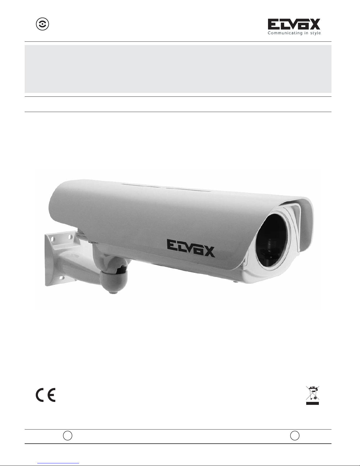
CONTENITORE STAGNO POE
POE WATERPROOF HOUSING
Art. 5299/POE
MANUALE PER IL COLLEGAMENTO E L’USO - INSTALLATION AND OPERATION MANUAL
I GB
2/2012
RL.00
Cod. S6I.529.POE
Page 2
DATI TECNICI SCHEDA DI ALIMENTAZIONE
Alimentazione scheda: pre-cablata, alimentata tramite standard PoE 802.3af (48Vdc)
Potenza assorbita dal riscaldamento: 3,5W
ISTRUZIONI PER L’ALLOGGIAMENTO DELLA TELECAMERA
1) Fissare nella posizione desiderata il supporto (1) (fig.1) usando viti diametro 8mm. con appositi tasselli.
2) Svitare le due viti nel lato sinistro della custodia (2) (fig.2) e procedere all’apertura. Il coperchio superiore ruota di 180° tramite il sistema a cerniera.
3) Passare il cavo Ethernet attraverso il supporto (1) (fig.1)
4) Effettuare i collegamenti elettrici (fig.4).
5) Allentare le 4 viti di bloccaggio della slitta interna e estrarre la stessa facendola scorrere leggermente verso il retro (fig.3).
6) Installare la telecamera nella posizione desiderata fissandola con apposita vite e rondella isolante(fig.3), quindi riposizionare la slitta interna e fissare le 4 viti di bloccaggio.
7) Effettuare i collegamenti elettrici tra telecamera e circuito di alimentazione prestando attenzione
che la tensione di rete sia compatibile con la tensione di alimentazione della telecamera
8) Richiudere la custodia procedendo in senso inverso all’apertura e serrare con cura le due viti nel lato
sinistro della custodia, quindi serrare opportunamente i pressacavi).
N.B.
Se è necessario centrare l’obiettivo con una telecamera di grandi dimensioni agire come segue:
5.1) Allentare le 4 viti di bloccaggio della slitta interna (4) ed estrarre la stessa facendola scorrere leggermente verso il retro e toglierla definitivamente.
5.2) Allentare le 2 viti di bloccaggio della slitta interna (5) ed estrarre la stessa facendola scorrere leggermente verso il retro
6.1) Installare la telecamera nella posizione desiderata fissandola con apposita vite e rondella isolante
(fig.3), quindi riposizionare la slitta interna (5) e fissare le 2 viti di bloccaggio.
AVVERTENZE
PRIMA DI ACCEDERE AI DISPOSITIVI DI COLLEGAMENTO, DEVONO ESSERE SCOLLEGATI TUTTI I CIRCUITI DI ALIMENTAZIONE.
Assicurarsi che a monte dell’impianto ci sia un adeguato dispositivo di sezionamento avente distanza
minima dei contatti di 3mm.
LE ISTRUZIONI DEVONO ESSERE CONSERVATE PER USO FUTURO.
2/8
5299/POE
I
Page 3
TECHNICAL DATA OF THE FEED BOARD
Board feed: pre-cabled, powered by standard PoE 802.3af (48Vdc)
Input power of the heating: 3,5W
INSTRUCTIONS FOR THE CAMERA SETTING
1) Fix the bracket in the required position (1) (fig.1) by means of screws of diam. 8 mm with special small
blocks.
2) Unscrew the screws of the left side (2) (fig. 2) and open the housing. The topo cover has a rotation
of 180°.
3) Insert the Ethernet cable through the bracket (1) (fig. 1).
4) Connect the electrical connections (fig.4) following diagram on right side.
5) Unscrew the 4 fastening screw of internal slide and remove it by movement on rear direction (fig.3).
6) Install the camera in the required position and fasten it by means of the special screw and insula-
ting washer(fig.3), then fasten the 4 screw of internal slide.
7) Connect the electrical connections between feeding board and camera and make sure that you are
using the correct voltage.
8) Close the housing by following the opening opposite procedure and fasten the 2 screws on the left
side of housing then clamp appropriately the cable-press device.
NOTE
For adjusting the lens with the window of the housing, make the following:
5.1)Unscrew the 4 fastening screw of internal slide (4) and remove it by movement on rear direction and
remove it definitively.
5.2)Unscrew the 2 fastening screws of internal slide (5) and remove it by movement on rear direction.
6.1)Install the camera in the required position and fasten it by means of the special screw and insula-
ting washer (fig.3), then fasten the 2 screws of internal slide (5).
WARNINGS
BEFORE APPROACHING THE CONNECTING DEVICES, ALL OF THE FEED CIRCUITS
MUST BE DISCONNECTED.
Make sure that at the beginning of the equipment there is a suitable sectioning device having a minimum
distance of the contacts of 3 mm.
THE INSTRUCTIONS MUST BE KEPT FOR FUTURE USE.
3/8
5299/POE
GB
Page 4

5299/POE
4/8
nr. 3 fori d.9 mm.
no.3 holes dia.9 mm.
DIMENSIONI - DIMENSIONS
Fig. 1
1
Page 5

5299/POE
5/8
Fig. 2
Fig. 3
Fig. 4
2
4
5
Ingresso RJ45 (verso LAN) Uscita RJ45 (verso network camera)
Imput RJ45 (to LAN) Output RJ45 (to network camera)
Page 6

NOTE
6/8
Page 7

5299/POE
7/8
AVVERTENZE PER L'INSTALLATORE
- Leggere attentamente le av ver ten ze contenute nel pre sen te do -
cu men to in quanto for ni sco no importanti indicazioni ri guar dan ti la sicurezza di in stal la zio ne, d'uso e di ma nu ten zio ne.
- Dopo aver tolto l'imballaggio assicurarsi dell'integrità del l'ap pa -
rec chio. Gli ele men ti dell'imballaggio (sacchetti di pla sti ca, po li sti ro lo espanso, ecc.) non devono essere lasciati alla portata
dei bambini in quanto potenziali fonti di pericolo. L'esecuzione
dell'impianto deve essere ri spon den te alle nor me CEI vigenti.
- È necessario prevedere a monte dell'alimentazione un
appropriato in ter rut to re di tipo bipolare facilmente accessibile
con separazione tra i contatti di almeno 3mm.
- Prima di col le ga re l'apparecchio ac cer tar si che i dati di targa
siano rispondenti a quelli della rete di di stri bu zio ne.
- Questo ap pa rec chio dovrà essere de sti na to solo all'uso per il
quale è stato espres sa men te concepito, e cioè per sistemi di citofonia o videocitofonia. Ogni altro uso è da con si de rar si im pro prio e quindi pericoloso. Il costruttore non può essere
con si de ra to re spon sa bi le per even tua li danni derivanti da usi
impropri, erronei ed ir ra gio ne vo li.
- Prima di ef
fet tua re qual si a si operazione di pu li zia o di ma nu ten zio ne, disinserire l'apparecchio dalla rete di ali men ta zio ne
elettrica, spe gnen do l'interruttore del l'im pian to.
- In caso di guasto e/o di cattivo fun zio na men to del l'ap pa rec chio,
togliere l'ali men ta zio ne me dian te l'interruttore e non ma no met tere l’apparecchio. Per l'even tua le ri pa ra zio ne ri vol ger si so la men te ad un centro di assistenza tecnica autorizzato dal
costruttore. Il mancato ri spet to di quanto so pra può com pro met te re la si cu rez za del l'ap pa rec chio.
-
Non ostru i re le aperture o fessure di ven ti la zio ne o di smaltimento
calore e non esporre l’apparecchio a stillicidio o spruzzi d’acqua.
Nessun oggetto pieno di liquido, quali vasi, deve essere posto sull’apparecchio.
- L'installatore deve as si cu rar si che le in for ma zio ni per l'uten te
siano pre sen ti sugli ap pa rec chi derivati.
- Tutti gli apparecchi costituenti l'impianto devono essere de sti na ti esclu si va men te all'uso per cui sono stati con ce pi ti.
- ATTENZIONE: per evitare di ferirsi, questo apparecchio deve
essere assicurato al pavimento/alla parete secondo le istruzioni
di installazione.
- Questo do cu men to dovrà sem pre ri ma ne re allegato alla do cu men ta zio ne dell'impianto.
Direttiva 2002/96/CE (WEEE, RAEE).
Il simbolo del cestino barrato riportato sull’apparecchio indica che il prodotto, alla fine della propria vita utile, do-
vendo essere trattato separatamente dai rifiuti domestici,
deve essere conferito in un centro di raccolta differenziata per apparecchiature elettriche ed elettroniche oppure riconsegnato al rivenditore al momento dell’acquisto di una nuova apparecchiatura
equivalente.
L’utente è responsabile del conferimento dell’apparecchio a fine
vita alle appropriate strutture di raccolta. L’adeguata raccolta differenziata per l’avvio successivo dell’apparecchio dismesso al riciclaggio, al trattamento e allo smaltimento ambientalmente
compatibile contribuisce ad evitare possibili effetti negativi sull’ambiente e sulla salute e favorisce il riciclo dei materiali di cui è composto il prodotto. Per informazioni più dettagliate inerenti i sistemi
di raccolta disponibili, rivolgersi al servizio locale di smaltimento rifiuti, o al negozio in cui è stato effettuato l’acquisto.
Rischi legati alle sostanze considerate pericolose (WEEE).
Secondo la nuova Direttiva WEEE sostanze che da tempo sono utilizzate comunemente su apparecchi elettrici ed elettronici sono
considerate sostanze pericolose per le persone e l’ambiente.
L’adeguata raccolta differenziata per l’avvio successivo dell’apparecchio dismesso al riciclaggio, al trattamento e allo smaltimento
ambientalmente compatibile contribuisce ad evitare possibili effetti
negativi sull’ambiente e sulla salute e favorisce il riciclo dei materiali di cui è composto il prodotto.
SAFETY INSTRUCTIONS FOR INSTALLERS
- Carefully read the instructions on this leaflet: they give important
information on the safety, use and maintenance of the installation.
- After removing the packing, check the integrity of the set. Packing components (plastic bags, expanded polystyrene etc.) are
dangerous for children. Installation must be carried out according to national safety regulations.
- It is convenient to fit close to the supply voltage source a proper bipolar type switch with 3 mm separation (minimum) between contacts.
- Before connecting the set, ensure that the data on the label correspond to those of the mains.
- This apparatus must only be used for the purpose for which it
was expressly designed, e.g. for audio or video door entry systems. Any other use may be dangerous. The manufacturer is
not responsible for damage caused by improper, erroneous or
irrational use.
- Before cleaning or maintenance, disconnect the set.
- In the event of faults and/or malfunctions, disconnect from the
power supply immediately by means of the switch and do not
tamper with the apparatus.
- For repairs apply only to the technical assistance centre authorized by the manufacturer.
- Safety may be compromised if these instructions are disregarded.
- Do not obstruct opening of ventilation or heat exit slots and do
not expose the set to dripping or sprinkling of water. No objects
filled with liquids, such as vases, should be placed on the apparatus.
- Installers must ensure that manuals with the above instructions
are left on connected units after installation, for users' information.
- All items must only be used for the purposes designed.
- WARNING: to prevent injury, this apparatus must be securely
attached to the floor/wall in accordance with the installation instructions.
- This leaflet must always be enclosed with the equipment.
Directive 2002/96/EC (WEEE)
The crossed-out wheelie bin symbol marked on the product indicates that at the end of its useful life, the product
must be handled separately from household refuse and
must therefore be assigned to a differentiated collection centre for
electrical and electronic equipment or returned to the dealer upon
purchase of a new, equivalent item of equipment.
The user is responsible for assigning the equipment, at the end of
its life, to the appropriate collection facilities.
Suitable differentiated collection, for the purpose of subsequent recycling of decommissioned equipment and environmentally compatible treatment and disposal, helps prevent potential negative
effects on health and the environment and promotes the recycling
of the materials of which the product is made. For further details regarding the collection systems available, contact your local waste
disposal service or the shop from which the equipment was purchased.
Risks connected to substances considered as dangerous
(WEEE).
According to the WEEE Directive, substances since long usually
used on electric and electronic appliances are considered dangerous for people and the environment. The adequate differentiated
collection for the subsequent dispatch of the appliance for the recycling, treatment and dismantling (compatible with the environment) help to avoid possible negative effects on the environment
and health and promote the recycling of material with which the
product is compound.
Page 8

CERT n° 9110.ELVO
UNI EN ISO 9001:2008
FILIALI ESTERE
ELVOX Costruzioni elettroniche S.p.A. - ITALY
Via Pontarola, 14/a - 35011 Campodarsego (Padova)
Tel 049 9202511 - Fax 049 9202603 - info@elvox.com
Telefax Export Dept. +39/049 9202601 - elvoxexp@elvox.com
www.elvox.com
ELVOX Austria GmbH
Grabenweg 67
A-6020 Innsbruck
Milano
Via Conti Biglia, 2
20162 Milano
Torino
Strada del Drosso, 33/8
10135 Torino
FILIALI ITALIA
ELVOX Shanghai Electronics Co. LTD
Room 2616, No. 325 Tianyaoqiao Road
Xuhui District
200030 Shanghai Cina
 Loading...