

Page 1
Manuale per l’installazione e l’uso
Installation and operation manual
46260.5P
46260.9P
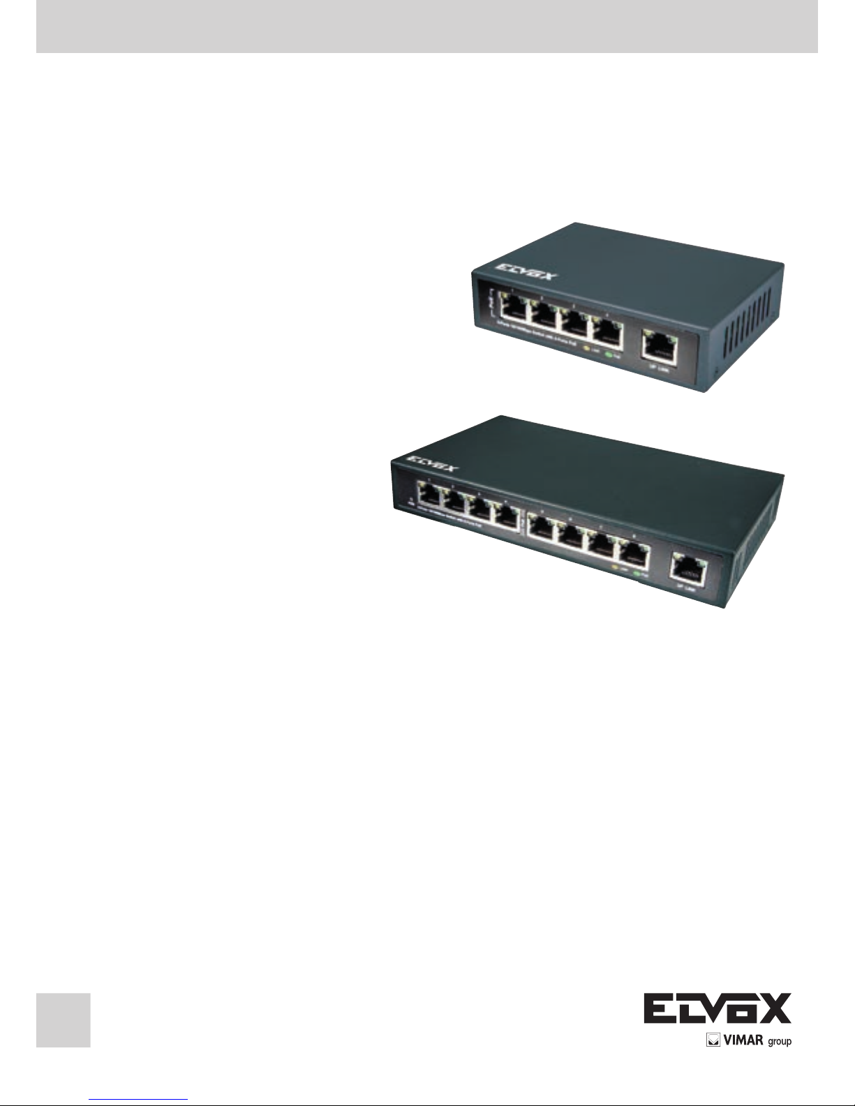
Switch PoE
PoE Switch
Page 2

2
I
Manuale del prodotto
Descrizione del prodotto
Lo switch PoE 10/100 Mbps unmanaged può fornire una connessione di rete diretta che integra le capacità di rete Fast Ethernet
100 Mbps e Ethernet 10 Mbps. Può rilevare e identicare automaticamente se i dispositivi collegati, quali una telecamera IP,
sono conformi agli standard IEEE802.3af e IEEE802.3at e fornire loro alimentazione. Lo switch PoE 10/100 Mbps unmanaged
facilita l'implementazione di AP wireless, telecamera IP e apparecchiature di rete basate su IP.
PoE: questa tecnologia descrive un sistema per la trasmissione di alimentazione elettrica e dati a dispositivi remoti (telefono IP,
AP wireless, telecamere IP ecc.) tramite doppino ritorto standard su rete Ethernet.
Convenzioni
La parola "switch" in questo manuale fa riferimento a uno switch PoE 10/100 Mbps unmanaged senza requisiti speciali.
Caratteristiche
• Fino a 30 W di potenza per porta.
• Conforme allo standard PoE IEEE802.3at e precedenti.
• Compatibile con tutti i dispositivi IEEE802.3at e simili.
• Sicuro: i dispositivi a bassa potenza ricevono solo la potenza necessaria
• Alimentazione sicura e afdabile ai punti di accesso WLAN
• Riconoscimento automatico e protezione dai terminali Ethernet non standard
• Supporta applicazioni 10/100 base-T
• Plug-and Play, non serve congurazione
• Risparmio no all'83% di potenza con la tecnologia green
Guida all'installazione
Utilizzare esclusivamente gli accessori in dotazione con lo switch.
lnstallazione
Per installare lo switch PoE attenersi a questa procedura:
1) Collocare lo switch su una supercie piana.
2) Rimuovere la pellicola dai cuscinetti di gomma adesivi.
3) Capovolgere lo switch e applicare i cuscinetti di gomma negli incavi ad ogni angolo del lato inferiore dello switch.
4) Per le installazioni sse, bloccare i ganci in dotazione sui lati dello switch. Bloccare quindi lo switch nella posizione deside-
rata.
Nota:
1. Non collocare oggetti pesanti sullo switch. Mantenere una buona aerazione intorno allo switch.
2. Assicurarsi che l'alimentazione sia spenta prima di scollegare l'alimentatore.
Accensione
Collegare il cavo di alimentazione, inserire la spina. L'alimentazione allo switch inizia automaticamente e gli indicatori LED si
comportano come segue:
1. L'indicatore LED di alimentazione si accende.
2. Ad eccezione delle spie della porta PoE, tutte le altre spie si spengono dopo un breve lampeggio che segnala un reset del
sistema.
Nota:
controllare l'alimentazione e la relativa connessione se gli indicatori LED non si comportano come descritto sopra.
Page 3
1
I
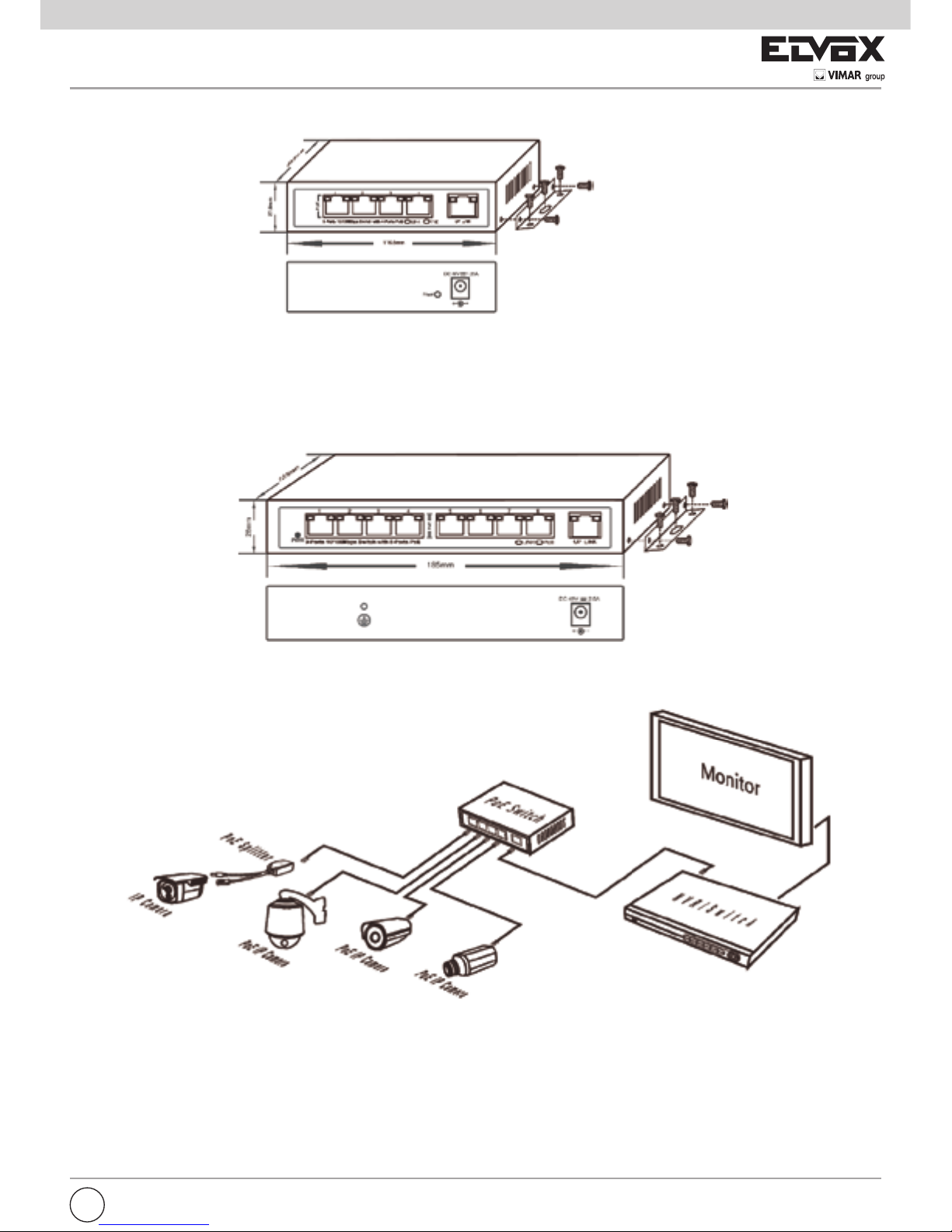
Figura 3: Schema di collegamento
Figura 1: Schema di installazione ssa per switch 5 porte 10/100Mbps con 4 porte PoE
Figura 2: Schema di installazione ssa per switch 9 porte 10/100Mbps con 8 porte PoE
Page 4

2
I
Identicazione dei componenti esterni
Utilizzare esclusivamente gli accessori in dotazione con lo switch.
lndicatore Stato lndicazione
Alimentazione ON Alimentazione accesa
OFF Alimentazione spenta
Stato PoE ON Dispositivo PD PoE collegato alla porta, funzionamento corretto
Lampeggiante Cortocircuito PoE o sovraccarico di corrente
OFF Nessun PD è collegato alla porta corrispondente oppure non è applicata alimentazione
conforme ai limiti di alimentazione della porta.
Link ON Collegato a dispositivo 10M o 100M
Lampeggiante Funzionamento corretto della trasmissione dati
OFF Nessun dispositivo connesso
Nota:
assicurarsi che i PD collegati allo switch siano conformi a IEEE802.3at.
Priorità Se il consumo energetico di tutti i PD PoE è superiore alla potenza massima, questa funzione interrompe
l'alimentazione alla porta con minore priorità per proteggere il sistema.
Ad esempio, nel caso di uno switch PoE a 4 porte: le porte 1, 2 e 4 utilizzano 16 W (la potenza massima per
porta è 30 W) e la potenza totale del sistema è 48 W. Se viene inserito un ulteriore PD nella porta 3 con 13
W di potenza, il sistema interrompe l'alimentazione alla porta 4 a causa del sovraccarico di potenza. Come
risultato le porte 1 e 2 utilizzeranno 16 W, la porta 3 utilizzerà 13 W e la porta 4 non riceverà alimentazione.
Porta PoE: queste porte supportano la funzione PoE che integra alimentazione e dati sullo stesso cavo Ethernet. È pos-
sibile stimare lo stato di funzionamento di ciascuna porta sul LED del pannello anteriore.
Porta Ethernet: ad eccezione delle porte PoE, le altre porte sono di tipo Ethernet RJ45. Tutte le porte supportano Auto MDI-
MDIX, plug and play.
È inoltre possibile stimare lo stato di funzionamento di ciascuna porta sul LED del pannello anteriore.
N. modello
Switch 10/100M a 5 porte con PoE a 4 porte Switch 10/100M a 9 porte con PoE a 8 porte
Standard
IEEE802.3at
Porte PoE 4 porte PoE 8 porte PoE
Porte Up Link 1 porta Up Link 1 porta Up Link
LED Alimentazione (rosso); PoE ln-Uee (arancione); 10/100 LINK/ACT (verde)
Requisiti alimentazione 100 ~240 Vca - 50/60 Hz
Requisiti alimentazione alimentatore
Ingresso: 100 ~240 Vca - 50/60 Hz
2 A; Uscita: 48 V, 1,25 A
Ingresso: 100 ~240 Vca - 50/60 Hz
2,5 A; Uscita: 48 V, 2,5 A
Capacità di scambio totale 1,0 Gbps 1,8 Gbps
Consumo energetico/Dissipazione 60 Watt Max. 120 Watt Max.
Uscita alimentazione PoE Per porta 48 Vdc, 620mA, Max. 30 Watt
Tipo alimentazione PoE 1 /2(+), 3/6(-), Modo-A, End-Span
Budget di potenza PoE PoE Max. 50 W PoE Max. 110 W
Conformità normativa FCC Parte 15 Classe A, CE
Conformità agli standard IEEE 802.3: 10 Base
IEEE 802.3u: 100 Base-TX
IEEE 802.3x: Flow Control
IEEE 802.3ad: Port trunk with LACP
IEEE 802.1D: Spanning tree protocol
IEEE 802.1P: CIass of service
IEEE 802.1x: Port Authentication Network Control
IEEE 802.3at: Power over Ethernet
Temperatura di esercizio: 0-50 °C; Umidità relativa: 20~95%
Conservazione: Temperatura: -10~70 °C
Umidità relativa: 20~95% (senza condensa)
Dimensione 116,6 x 83,6 x 27,8 mm 185 x 103 x 28 mm
Speciche
Page 5

3
EN
Introduction of product
Product overview
10/100Mbps unmanaged PoE switch can provide the seamless network connection which integrates 100Mbps Fast Ethernet
and 10Mbps Ethernet network capabilities. lt can automatically detect and identify whether connected devices such as IP camera comply with standard IEEE802.3af and IEEE802.3at, and supply power for them. 10/100Mbps unmanaged PoE switch makes
the deployment of wireless AP, IP camera and IP-based network equipment become easier.
PoE:This technology describes a system to transmit electrical power, along with data, to remote davices (IP phone, Wireless AP,
IP camares, etc.) over standard twisted-pair cable in an Ethernet network.
Convention
The “switch” mentioned in this manual stands for 10/100 Mbps unmanaged PoE swltch if without a special raquest.
Features
• Up to 30W of Power on
• Complies to IEEE802.3at PoE standard and is backward
• Compatible with all IEEE802.3 at or Legacy
• Safe: low power devices receive only the power they need
• Safe and reliable power to WLAN access points
• Automatic detection and protection of Non-standard Ethernat tarminals
• Supports 10/100 base-T applications
• Plug-and Play no conguration required
• Save up to 83% power with green technology
Installation guide
Please use the accessories equipped with the switch only.
lnstallation
Please install the PoE switch according to the following steps:
1) Place the switch on a at desk.
2) Remove the adhesive backing papers from the rubber cushions.
3) Turnover the switch and attach the supplied four rubber cushions to the recessed areas on the bottom at each corner of the
switch.
4) For xed installation, please lock the attached hangers on the sides of the switch. And then lock the switch on the specic
position.
Note:
1. Please don’t place any heavy thing on the switch. And please keep the good ventilation environment for the switch.
2. Please make sure the power is off before unplugging the power adapter.
Power On
Connect the power cord, plug it in. Powering on the switch, it will automatically initialize and is LED indicators will respond as
follows:
1. The power LED indicator will light up.
2. Except the PoE port lights, all the other lights will be off after ashing momentarily, which represents a resetting of the sy-
stem.
Note:
Please check the power and its connection if the LED indicators don’t respond as described above.
Page 6

4
EN
Figure 3: Connection diagram
Figure 1: Fixed lnstallation Diagram for 5-Ports 10/100Mbps Switch wilh 4-Ports PoE
Figure 2: Fixed lnstallation Diagram for 9-Ports 10/100Mbps Switch wilh 8-Ports PoE
Page 7

5
EN
Identifying external components
Please use the accessories equipped with the switch only.
lndicator Status lndication
Power ON Power on
OFF Power off
PoE Status ON PoE PD device connected to the port, working properly
Flashing Short PoE power circuit or overloaded power current
OFF No PD is connected to the corresponding port, or no power is supplied according to the power
limits of the port
Link ON Connected 10M or 100M device
Flashing Data transmission properly
OFF No device is connected
Note:
Make sure the PDs you connected to the switch are complaint with IEEE802.3at.
Priority: lf all PoE PDs power consumption is more than the max power, this function will cut off the power of the lowest priority
port to protect the system.
For example, for 4-Ports PoE switch: port 1. 2 and 4 is using 16W (max power for per port is 30W}, the system power
is 48W in total. lf there is an additional PD inserted to Port 3 with 13W, and then the system will cut off the power of
Port 4 because of the overloaded power, this means Port1, 2 will use 16W, and Port 3 will use 13W, no power will be
supplied to Port 4.
PoE Port:These ports support PoE function which integrates power and data onto one Ethernet cable. You can estimate the
working status of each port on front paneI LED.
Ethernet Except PoE ports, other ports are Ethernet RJ45 ports. All ports support Auto MDI-MDIX, plug and play.
Port: Also you can estimate the working status of each port on front paneI LED.
Model No. 5-Ports 10/100M Switch with 4-Ports PoE 9-Ports 10/100M Switch with 8-Ports PoE
Standard
IEEE802.3at
PoE Ports 4 PoE ports 8 PoE ports
Up Link Ports 1 Up Link Port 1 Up Link Port
LED Power (red); PoE ln-Uee (orange); 10/100 LINK/ACT (green)
Power Requlrement 100-240V AC, 50/60Hz
Adapter Power Requirement Input: 100-240VAC, 50/60Hz,
2.0A; Output: 48V, 1.25A
Input: 100-240VAC, 50/60Hz,
2.5A; Output: 48V, 2.5A
Exchange Capaclty 1.0 Gbps 1.8 Gbps
Power Consumption / Dissipation 60 Watt Max. 120 Watt Max.
PoE Power Output Per Port 48 Vdc, 620mA. Max. 30 Watts
PoE Power Supply Type 1 /2(+), 3/6(-), Mode-A, End-Span
PoE Power Budget PoE Max. 50W PoE Max. 110W
Regulation Compliance FCC Part 15 Class A, CE
Standard Compliance IEEE 802.3: 10 Base
IEEE 802.3u: 100 Base-TX
IEEE 802.3x: Flow Control
IEEE 802.3ad: Port trunk with LACP
IEEE 802.1D: Spanning tree protocol
IEEE 802.1P: CIass of service
IEEE 802.1x: Port Authentication Network Control
IEEE 802.3at: Power over Ethernet
Operating Temperature : 0-50 Degree °C; Relative Humidity: 20~95%
Storage Temperature: -10~70 Degree °C
Relativa Humldlty: 20~95% (non-condensing)
Dimension 116.6x83.6x27.8 mm 185x103x28 mm
Specication
Page 8

Vimar SpA: Viale Vicenza, 14
36063 Marostica VI - Italy
Tel. +39 0424 488 600 - Fax (Italia) 0424 488 188
Fax (Export) 0424 488 709
www.vimar.com
49400820A0 00 15 05
VIMAR - Marostica - Italy
AVVERTENZE PER L’INSTALLATORE
- Leggere attentamente le av ver ten ze contenute nel pre sen te do cumen to in quanto for ni sco no importanti indicazioni ri guar dan ti la sicurezza di in stal la zio ne, d’uso e di ma nu ten zio ne.
- Dopo aver tolto l’imballaggio assicurarsi dell’integrità del l’ap pa recchio. Gli ele men ti dell’imballaggio (sacchetti di pla sti ca, po li sti ro lo
espanso, ecc.) non devono essere lasciati alla portata dei bambini
in quanto potenziali fonti di pericolo. L’esecuzione dell’impianto deve
essere ri spon den te alle nor me CEI vigenti.
- È necessario prevedere a monte dell’alimentazione un appropriato
in ter rut to re di tipo bipolare facilmente accessibile con separazione
tra i contatti di almeno 3mm.
- Prima di col le ga re l’apparecchio ac cer tar si che i dati di targa siano
rispondenti a quelli della rete di di stri bu zio ne.
- Questo ap pa rec chio dovrà essere de sti na to solo all’uso per il quale
è stato espres sa men te concepito, e cioè per sistemi di TVCC. Ogni
altro uso è da con si de rar si im pro prio e quindi pericoloso. Il costrut-
tore non può essere con si de ra to re spon sa bi le per even tua li danni
derivanti da usi impropri, erronei ed ir ra gio ne vo li.
- Prima di ef fet tua re qual si a si operazione di pu li zia o di ma nu ten zio ne,
disinserire l’apparecchio dalla rete di ali men ta zio ne elettrica, spe-
gnen do l’interruttore del l’im pian to.
-
In caso di guasto e/o di cattivo fun zio na men to del l’ap pa rec chio, togliere
l’ali men ta zio ne me dian te l’interruttore e non ma no met tere l’apparec
chio. Per l’even tua le ri pa ra zio ne ri vol ger si so la men te ad un centro di
assistenza tecnica autorizzato dal costruttore. Il mancato ri spet to di
quanto so pra può com pro met te re la si cu rez za del l’ap pa rec chio.
- Non ostru i re le aperture o fessure di ven ti la zio ne o di smaltimento ca
lore e non esporre l’apparecchio a stillicidio o spruzzi d’acqua. Nessun
oggetto pieno di liquido, quali vasi, deve essere posto sull’apparecchio.
- L’installatore deve as si cu rar si che le in for ma zio ni per l’uten te siano
pre sen ti sugli ap pa rec chi derivati.
- Tutti gli apparecchi costituenti l’impianto devono essere de sti na ti
esclu si va men te all’uso per cui sono stati con ce pi ti.
- ATTENZIONE: per evitare di ferirsi, questo apparecchio deve essere
assicurato al pavimento/alla parete secondo le istruzioni di installazione
.
- Questo do cu men to dovrà sem pre ri ma ne re allegato alla do cu men tazio ne dell’impianto.
Direttiva 2002/96/CE (WEEE, RAEE).
Il simbolo del cestino barrato riportato sull’apparecchio indica che
il prodotto, alla ne della propria vita utile, dovendo essere trattato separatamente dai riuti domestici, deve essere conferito in
un centro di raccolta differenziata per apparecchiature elettriche
ed elettroniche oppure riconsegnato al rivenditore al momento dell’acquisto di una nuova apparecchiatura equivalente.
L’utente è responsabile del conferimento dell’apparecchio a ne vita
alle appropriate strutture di raccolta. L’adeguata raccolta differenziata
per l’avvio successivo dell’apparecchio dismesso al riciclaggio, al trat-
tamento e allo smaltimento ambientalmente compatibile contribuisce ad
evitare possibili effetti negativi sull’ambiente e sulla salute e favorisce
il riciclo dei materiali di cui è composto il prodotto. Per informazioni più
dettagliate inerenti i sistemi di raccolta disponibili, rivolgersi al servizio locale di smaltimento riuti, o al negozio in cui è stato effettuato l’acquisto.
Rischi legati alle sostanze considerate pericolose (WEEE).
Secondo la nuova Direttiva WEEE sostanze che da tempo sono utilizzate comunemente su apparecchi elettrici ed elettronici sono considerate
sostanze pericolose per le persone e l’ambiente. L’adeguata raccolta
differenziata per l’avvio successivo dell’apparecchio dismesso al riciclaggio, al trattamento e allo smaltimento ambientalmente compatibile con-
tribuisce ad evitare possibili effetti negativi sull’ambiente e sulla salute e
favorisce il riciclo dei materiali di cui è composto il prodotto.
Il prodotto è conforme alla direttiva europea 2004/108/CE e
successive.
SAFETY INSTRUCTIONS FOR INSTALLERS
- Carefully read the instructions on this leaet: they give important information on the safety, use and maintenance of the installation.
- After removing the packing, check the integrity of the set. Packing
components (plastic bags, expanded polystyrene etc.) are dangerous
for children. Installation must be carried out according to national safety regulations.
- It is convenient to t close to the supply voltage source a proper bipolar type switch with 3 mm separation (minimum) between contacts.
- Before connecting the set, ensure that the data on the label corre-
spond to those of the mains.
- This apparatus must only be used for the purpose for which it was
expressly designed, e.g. for C.C.T.V. systems. Any other use may be
dangerous. The manufacturer is not responsible for damage caused
by improper, erroneous or irrational use.
- Before cleaning or maintenance, disconnect the set.
- In the event of faults and/or malfunctions, disconnect from the power
supply immediately by means of the switch and do not tamper with
the apparatus.
- For repairs apply only to the technical assistance centre authorized
by the manufacturer.
- Safety may be compromised if these instructions are disregarded.
- Do not obstruct opening of ventilation or heat exit slots and do not
expose the set to dripping or sprinkling of water. No objects lled with
liquids, such as vases, should be placed on the apparatus.
- Installers must ensure that manuals with the above instructions are
left on connected units after installation, for users’ information.
- All items must only be used for the purposes designed.
- WARNING: to prevent injury, this apparatus must be securely attached to the oor/wall in accordance with the installation instructions.
- This leaet must always be enclosed with the equipment.
Directive 2002/96/EC (WEEE)
The crossed-out wheelie bin symbol marked on the product
indicates that at the end of its useful life, the product must be
handled separately from household refuse and must therefore be
assigned to a differentiated collection centre for electrical and electronic
equipment or returned to the dealer upon purchase of a new, equivalent
item of equipment.
The user is responsible for assigning the equipment, at the end of its life,
to the appropriate collection facilities.
Suitable differentiated collection, for the purpose of subsequent recycling
of decommissioned equipment and environmentally compatible treatment and disposal, helps prevent potential negative effects on health
and the environment and promotes the recycling of the materials of which
the product is made. For further details regarding the collection systems
available, contact your local waste disposal service or the shop from
which the equipment was purchased.
Risks connected to substances considered as dangerous (WEEE).
According to the WEEE Directive, substances since long usually used
on electric and electronic appliances are considered dangerous for people and the environment. The adequate differentiated collection for the
subsequent dispatch of the appliance for the recycling, treatment and
dismantling (compatible with the environment) help to avoid possible negative effects on the environment and health and promote the recycling
of material with which the product is compound.
Product is according to EC Directive 2004/108/CE and fol-
lowing norms.
 Loading...