

Page 1
Guida rapida
Quick guide
46235.020
Telecamera Speedome IP full HD, zoom 20x (IR 100m)
Speedome Camera IP full HD, zoom 20x (IR 100m)
Page 2
2
I
Capitolo 1 Introduzione
1.1 Panoramica
La telecamera Speed Dome è un'apparecchiatura front-end utilizzata per acquisire video. La tecnologia di ip digitale consente
di riprendere immagini in tutte le direzioni e monitorare senza punti ciechi. Utilizza le tecnologie più avanzate, quali la tecnologia
di codica e decodica video ed è conforme al protocollo TCP/IP, SoC. ecc. per assicurare la stabilità e l'afdabilità del sistema.
L'unità comprende due parti: il dispositivo IP-CAM e il software di gestione centrale (abbreviato in CVM Elvox). Il CVM Elvox consente di centralizzare tutti i dispositivi via Internet o LAN e creare un buon impianto di sorveglianza che offre gestione unicata
e attivazione in remoto di tutti i dispositivi in rete.
Questo prodotto è ampiamente utilizzato nelle banche, nei sistemi di telecomunicazione, siti di fornitura elettrica, enti statali,
fabbriche, magazzini, centri urbani ecc. È inoltre la scelta ideale per aree di sorveglianza a medio e alto rischio.
1.2 Interfacce e parti
1
2
3
4
5
6
8
7
10
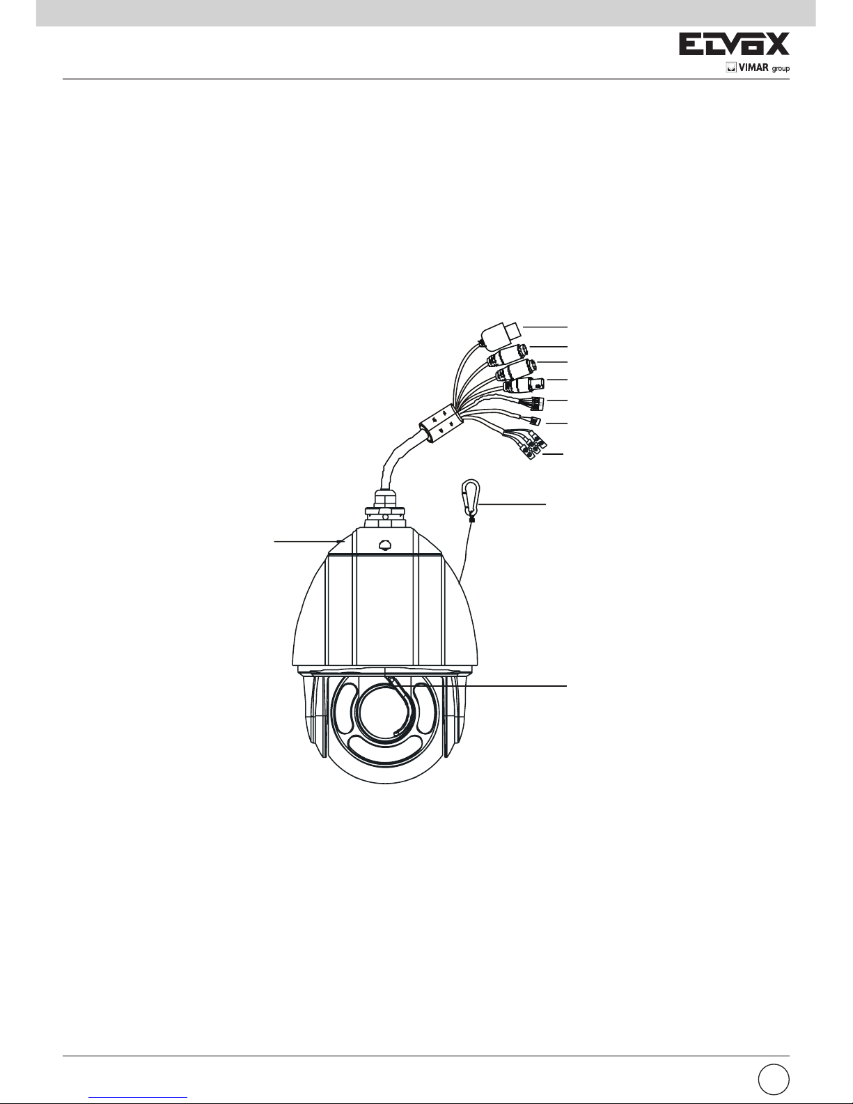
1 LAN 2 Uscita HP Audio 3 Ingresso MIC
4 Uscita CVBS Video 5 Ingresso allarme/Uscita allarme 6 RS485
7 Alimentazione 8 Cavo anticaduta 9 Piastra di base
10 Tergicristallo
Page 3
1
I
Capitolo 2 Installazione e connessione
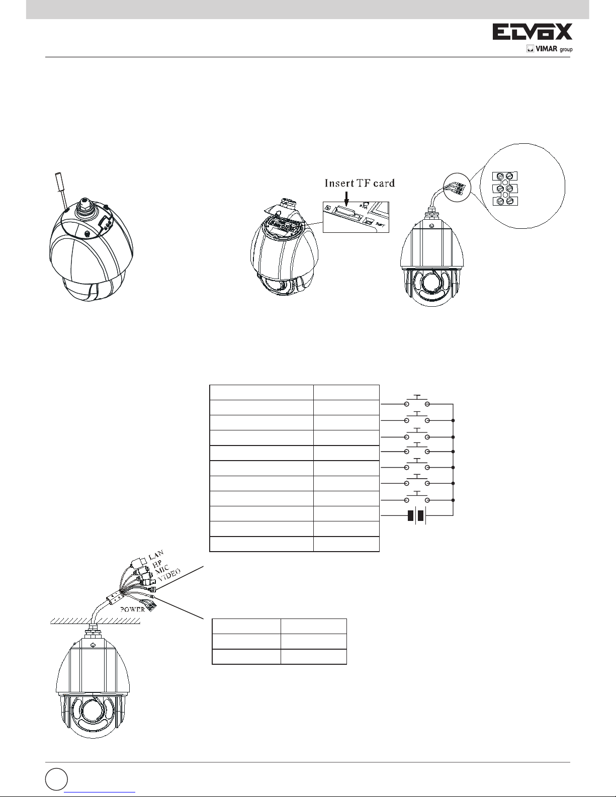
2.1 Installazione scheda TF e collegamento dell’alimentazione
Installare la scheda di archiviazione:
1 - Allentare le viti sse della cabina come illustrato di seguito.
2 - Inserire la scheda TF nello slot della scheda di archiviazione.
3 - Rimontare la cabina e ssarla con le viti.
1
2
3
4
5
6
8
9
7
10
2.2 Connessione
La PTZ Art. 46235.020 può gestire no a n°7 ingressi e 1 uscita allarme, con collegamento diretto degli allarmi sui contatti della
PTZ, secondo lo schema di gura 1 e 2.
1
2
3
4
5
6
8
9
7
10
Descrizione Colore
Allarme-IN1 Viola
Allarme-IN2 Grigio
Allarme-IN3 Bianco
Allarme-IN4 Rosa
Allarme-IN5 Rosso
Allarme-IN6 Nero
Allarme-IN7 Marrone
Allarme-n-COM Arancio/Nero
Allarme-OUT + Giallo/Nero
Allarme-OUT - Verde/Nero
Descrizione Colore
RS485TA Giallo
RS485TA Arancio
Fig. 1
Contatti N.O.
-
+
5-12 Vdc
-
+
5-12 Vdc
1
2
3
4
5
6
8
9
7
10
Computer
Router
NetworkCable
NetworkCable
N
e
t
w
o
r
k
C
a
b
l
e
NetworkCable
Internet
Sensor / Alarm
N
e
t
w
o
r
k
C
a
b
l
e
AC24V A
AC24V B
Earth
Terra
Page 4
2
I
1
2
3
4
5
6
8
9
7
10
Computer
Router
NetworkCable
NetworkCable
N
e
t
w
o
r
k
C
a
b
l
e
NetworkCable
Internet
Sensor / Alarm
N
e
t
w
o
r
k
C
a
b
l
e
Fig. 2
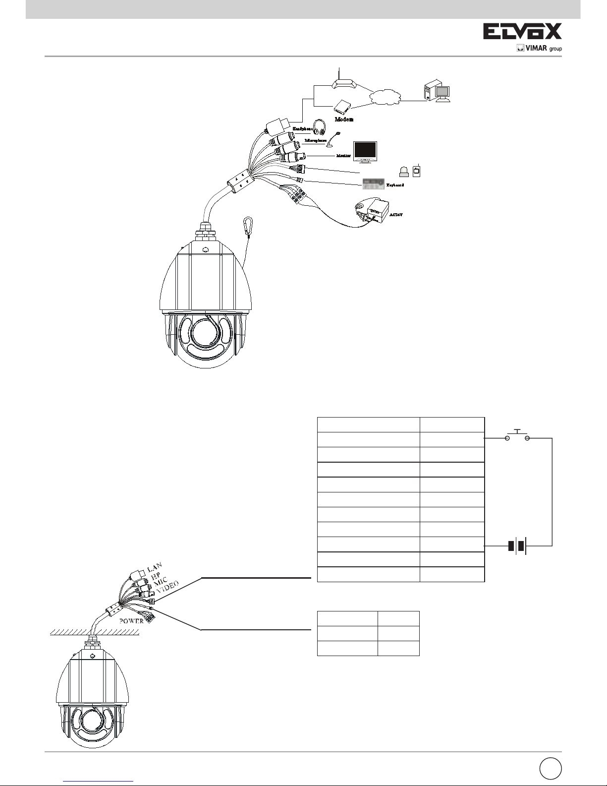
Nel caso di utilizzo della PTZ con NVR , è possibile utilizzare solo l’allarme n°1 (vedi Fig. 3).
Descrizione Colore
Allarme-IN1 Viola
Allarme-IN2 Grigio
Allarme-IN3 Bianco
Allarme-IN4 Rosa
Allarme-IN5 Rosso
Allarme-IN6 Nero
Allarme-IN7 Marrone
Allarme-n-COM Arancio/Nero
Allarme-OUT + Giallo/Nero
Allarme-OUT - Verde/Nero
Contatti N.O.
-
+
5-12 Vdc
Fig. 3
1
2
3
4
5
6
8
9
7
10
Descrizione Colore
RS485TA Giallo
RS485TA Arancio
Page 5
3
I
Uscita allarme:
a) Supporta l'uscita allarme a 1 canale incluse le connessioni OPEN e COM.
b) Opzioni: OFF, IN1. Se si seleziona OFF, non verrà emesso alcun allarme. Se si seleziona IN1, l'allarme viene emesso solo
quando l'ingresso allarme corrispondente attiva l'allarme.
c) Un interruttore passivo che consente all'utente di collegare i dispositivi di allarme.
- Collegamento RS485
È possibile collegare la tastiera per monitorare la speed dome tramite l'interfaccia RS485.
2.3 Installazione del CVM Elvox
Individuare il software CVM Elvox nel CD e fare doppio clic sul le di installazione "Setup.exe" per visualizzare la procedura di
installazione guidata. Installare il software seguendo le istruzioni visualizzate a video. Dopo aver completato l'installazione verranno visualizzate le icone CVM Elvox e IP-Tool sul desktop. Consultare il manuale dell'utente del software per maggiori dettagli.
Se è necessario installare IP-Tool separatamente, fare doppio clic sul pacchetto di installazione e installarlo seguendo le istru-
zioni a video. Al termine dell'installazione fare doppio clic sull'icona IP-Tool per avviarlo.
Capitolo 3 Accesso remoto da Internet Explorer
È possibile collegare IP-Cam tramite LAN o WAN. In questo documento viene utilizzato come esempio il browser Internet Explorer 6.0. Di seguito sono indicati i dettagli:
3.1 LAN
In una LAN è possibile accedere a IP-Cam in due modi: 1. accesso da IP-Tool; 2. accesso diretto da Internet Explorer.
3.1.1 Accesso tramite IP-Tool
1 - Assicurarsi che PC e IP-Cam siano collegati alla LAN e che IP-Tool sia stato installato sul PC dal CD.
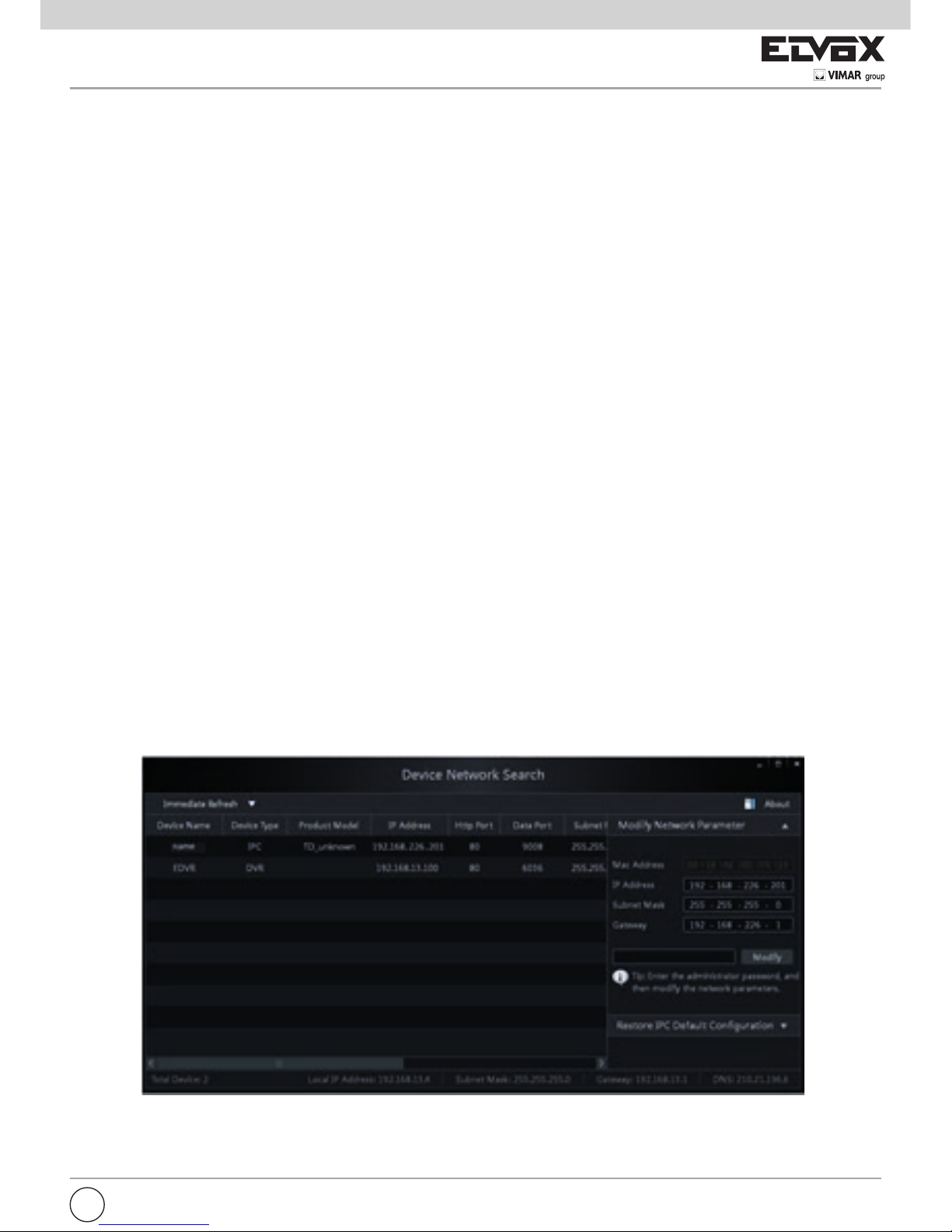
2 - Fare doppio clic sull'icona IP-Tool sul desktop per eseguire il software, come illustrato di seguito:
3 - Modicare l'indirizzo IP. L'indirizzo IP predenito di questa telecamera è 192.168.226.201. Fare clic sulle informazioni elen-
cate nella tabella sopra riportata per visualizzare le informazioni di rete sulla destra. Modicare l'indirizzo IP e il gateway
della telecamera e assicurarsi che l'indirizzo di rete si trovi nello stesso segmento della rete locale del computer. Modicare
l'indirizzo IP del dispositivo in base alla situazione specica.
- Collegamento dell’allarme
Ingresso allarme:
a) Sono disponibili sette diverse porte indipendenti per l’allarme (ALARM-IN1~7) e una porta di messa a terra (ALM-GND).
b) Sono disponibili tre stati di ingresso dell’allarme: “OFF/NC/NO” (Spento/Normalmente chiuso/Normalmente aperto). Se si sele-
ziona “OFF” il sistema non controlla lo stato di ALM-IN e ALM-GND. Se si seleziona “NO”, collegare la tensione DC 5V~DC12V
tra la porta dell’ingresso allarme ALM-IN e la porta di messa a terra (ALM-GND) per attivare l’allarme (vedi Fig .1). Se si seleziona “NC”, scollegare la tensione tra le porte di ingresso di allarme (ALM-IN) e la porta di messa a terra (ALM-GND) per attivare
l’allarme.
Page 6
4
Ad esempio, l'indirizzo del computer in uso è 192.168.13.4. Di conseguenza l'indirizzo della telecamera deve essere cambiato in
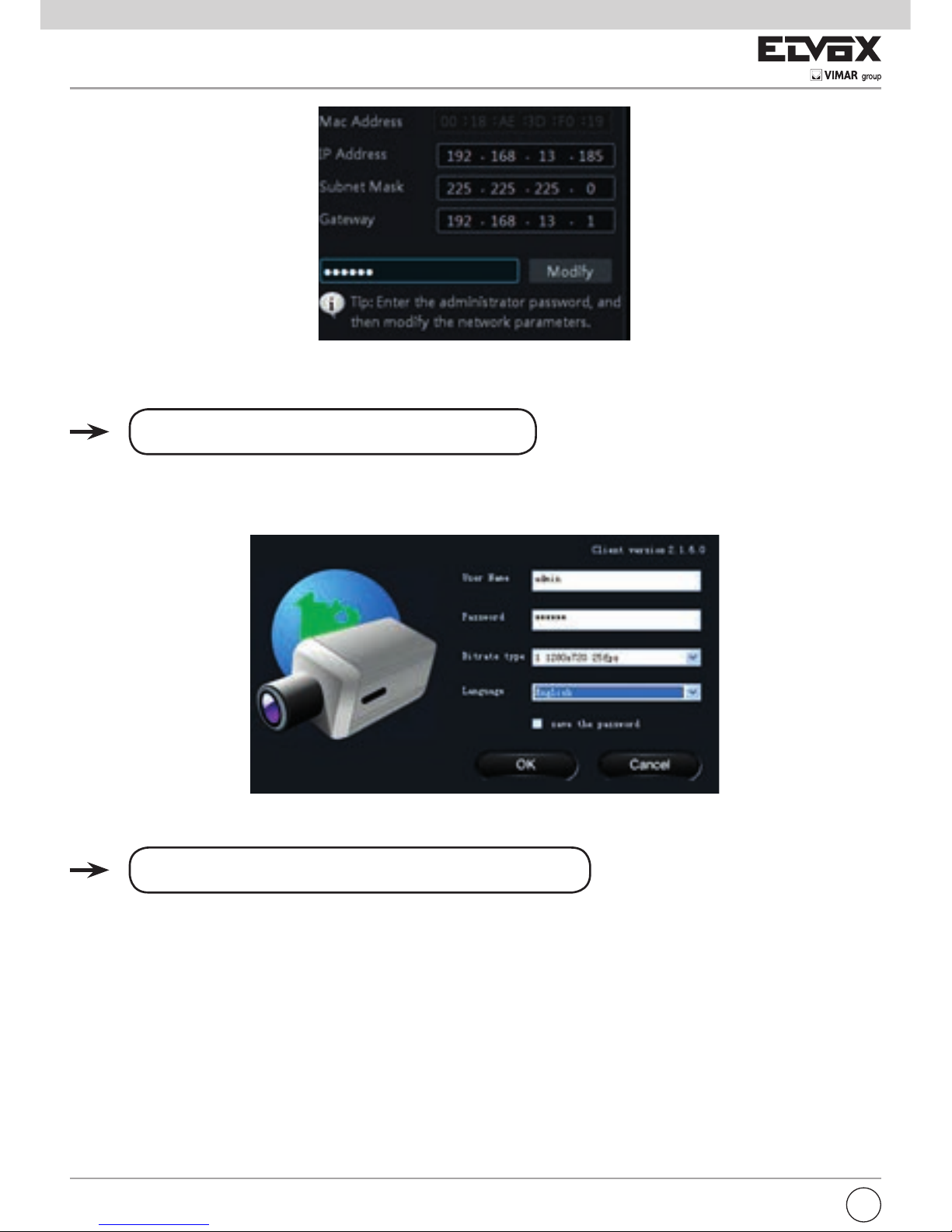
192.168.13.X. Dopo la modica inserire la password di amministratore e fare clic sul pulsante "Modica" per modicare l'impostazione.
La password predenita dell'amministratore è "123456".
4 - Fare doppio clic sull'indirizzo IP, il sistema aprirà Internet Explorer per collegare l'IP-CAM. Internet Explorer scarica automaticamente i controlli ActiveX. Dopo il download si apre la nestra di accesso illustrata di seguito.
Inserire il nome utente e la password per accedere.
Il nome utente predenito è "admin" e la password "123456".
3.1.2 Accesso diretto da Internet Explorer
Le impostazioni di rete predenite sono indicate di seguito:
Indirizzo IP: 192.168.226.201
Subnet Mask: 255.255.255.0
Gateway: 192.168.226.1
HTTP: 80
Porta dati: 9008
È possibile utilizzare le impostazioni predenite sopra riportate quando si esegue l'accesso alla telecamera per la prima volta.
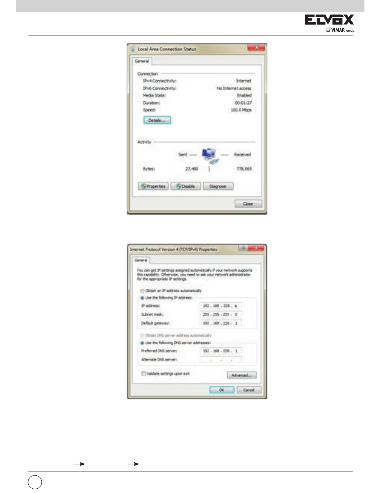
1 - Impostare manualmente l'indirizzo IP del PC e il segmento di rete come impostazioni predenite della telecamera IP. Aprire la
rete e il centro di condivisione. Fare clic su "Connessione alla rete locale (LAN)" per visualizzare la seguente nestra.
I
Page 7
5
Selezionare "Proprietà" quindi selezionare il protocollo Internet opportuno (ad esempio: IPV4). Fare quindi clic sul pulsante
"Proprietà" per impostare la rete del PC.
2 - Aprire Internet Explorer e inserire l'indirizzo predenito dell'IP-CAM e confermare. Internet Explorer scarica automaticamen-
te i controlli ActiveX.
3 - Dopo il download dei controlli ActiveX, viene visualizzata la nestra di dialogo di accesso.
4 - Inserire il nome e la password predenite quindi premere Invio.
3.2 WAN
Accedere alla telecamera tramite il router o il server virtuale, ad esempio:
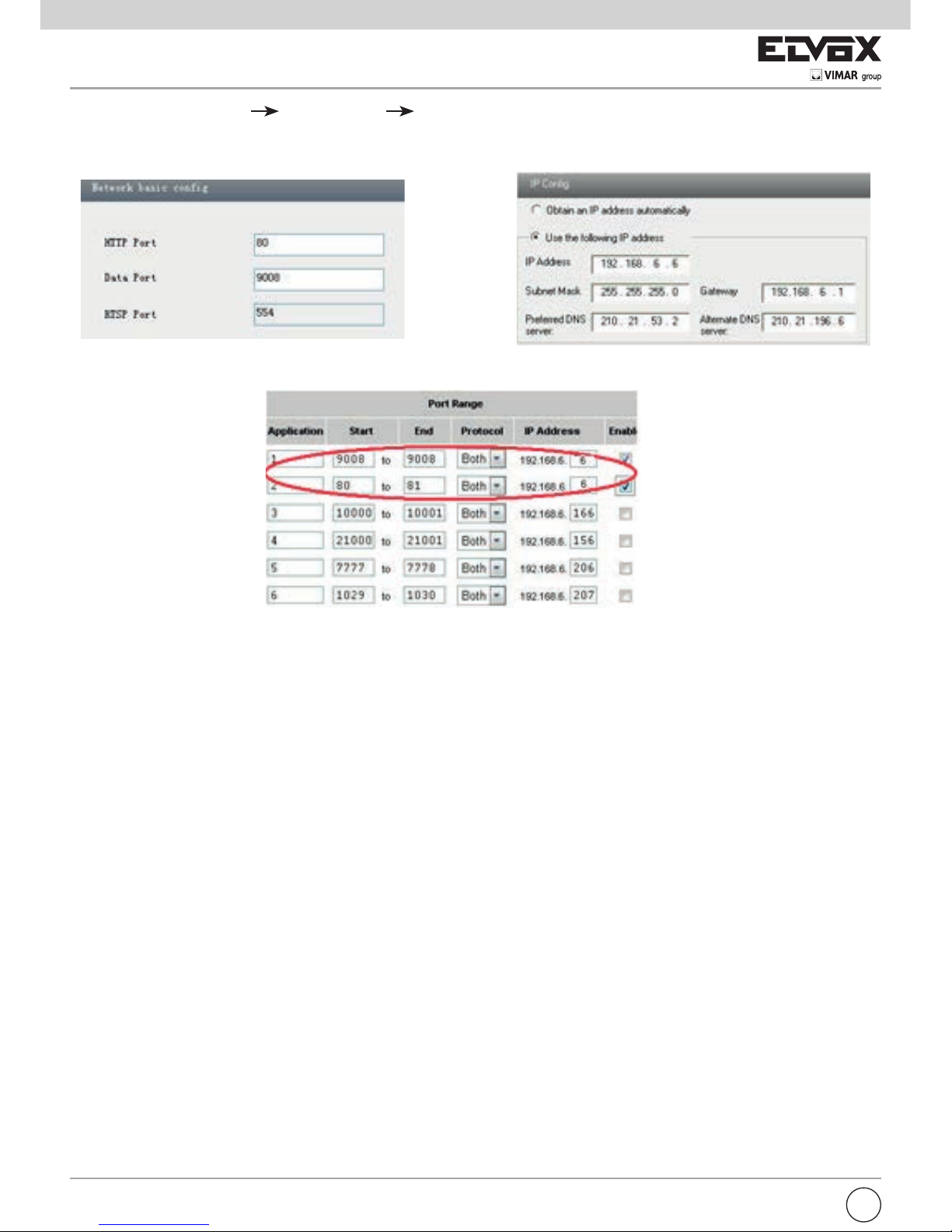
1 - Assicurarsi che la telecamera sia ben collegata tramite la LAN, quindi accedere alla telecamera tramite LAN e andare al
menu Cong Network Cong Port per impostare il numero di porta.
I
Page 8
6
2 - Andare al menu Cong Network Cong IP Address per modicare l'indirizzo IP.
3 - Accedere all'interfaccia di gestione del router tramite Internet Explorer per inoltrare l'indirizzo IP e la porta della telecamera
nel "Server virtuale".
4 - Aprire Internet Explorer e inserire l'IP WAN corrispondente e la porta http per accedere.
Impostazione porta Impostazione IP
Impostazione del router
I
Page 9
7
Capitolo 4 Visualizzazione dell'anteprima in remoto
4.1 Visualizzazione dell'anteprima in remoto
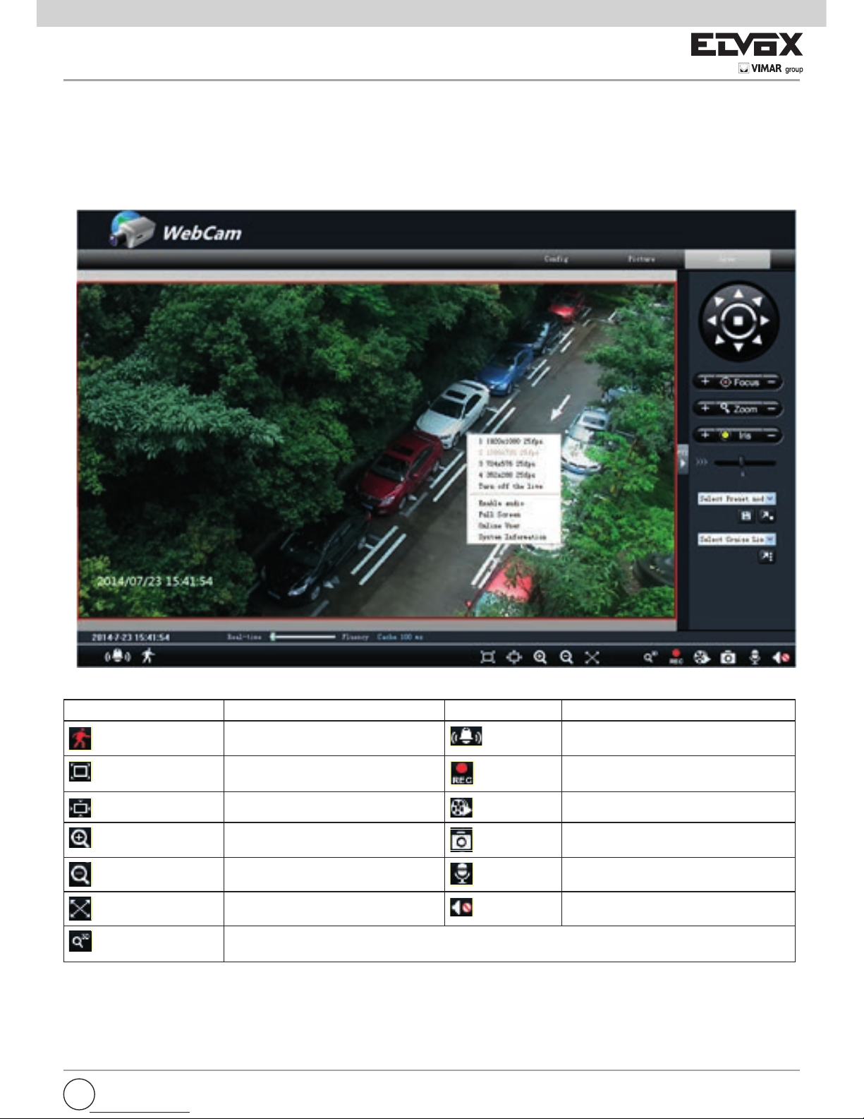
Dopo aver eseguito l'accesso viene visualizzata la seguente nestra.
Descrizione delle icone sull'interfaccia di visualizzazione dell'anteprima in remoto:
Icona Descrizione Icona Descrizione
Icona dell'allarme movimento
Icona dell'allarme sensore
Fix size (Ridimensiona)
Start/Stop record (Avvia/Interrompi
registrazione)
Actual size (Grandezza reale)
Playback (Riproduzione)
Zoom in (Zoom avanti)
Snap (Istantanea)
Zoom out (Zoom indietro)
Talk (Chat)
Full screen (Schermo intero)
Open/close audio (Apri/Chiudi audio)
Spostare il cursore per visualizzare l'immagine live in tutte le direzioni dopo aver fatto clic sul pulsante. Trascinare con il pulsante sinistro del mouse per eseguire lo zoom avanti sull'immagine live.
Fare clic con il pulsante destro del mouse per visualizzare un elenco a discesa:
Stream (Flusso): come opzione sono disponibili quattro ussi.
Turn off the live (Disattiva live): fare clic su questo elemento per chiudere l'anteprima live corrente.
Enable audio (Attiva audio): attiva la trasmissione audio in remoto.
I
Page 10
8
Full screen (Schermo intero): apre la visualizzazione a schermo intero. Fare doppio clic o fare clic con il pulsante destro del mouse per tornare
all'interfaccia precedente.
Online user (Utenti online): visualizza il numero di utenti online che hanno eseguito l'accesso al dispositivo.
System information (Informazioni del sistema): visualizza le informazioni sul dispositivo.
Fare clic sul pulsante PTZ per aprire il pannello di controllo PTZ. Nell'interfaccia di anteprima in remoto, è possibile visualizzare l'immagine da ogni
direzione utilizzando il pannello PTZ.
Di seguito è descritto il pannello di controllo:
Icona Descrizione
to rotate the dome upwardsͺ to rotate the dome downwards;
to rotate the dome towards left; to rotate the dome towards
to rotate the dome upwardsͺ to rotate the dome downwards;
per ruotare la telecamera verso l'alto;
per ruotare la telecamera verso il basso;
to rotate the dome upwardsͺ to rotate the dome downwards;
per ruotare la telecamera verso
sinistra;
per ruotare la telecamera verso destra;
per ruotare la telecamera in diagonale verso l'alto a sinistra;
per ruotare la telecamera in diagonale verso l'alto a destra;
per ruotare la telecamera in diagonale verso il basso a sini-
stra;
to rotate the dome diagonally up -left;ͺ to rotate the
per ruotare la telecamera in diagonale verso il basso a destra;
per interrompere la rotazione della telecamera.
to rotate the dome upwardsͺ to rotate the dome downwards;
to rotate the dome towards left; to rotate the dome towards
rightͺ
to rotate the dome diagonally up -left;ͺ to rotate the
dome diagonally up-right;
to rotate the dome diagonally down -
left;
to rotate the dome diagonally down -right; to stop
Trascinare la barra di scorrimento per regolare la velocità di rotazione della telecamera.
to rotate the dome upwardsͺ to rotate the dome downwards;
to rotate the dome towards left; to rotate the dome towards
rightͺ
to rotate the dome diagonally up -left;ͺ to rotate the
dome diagonally up-right;
to rotate the dome diagonally down -
left;
to rotate the dome diagonally down -right; to stop
Focus button. Click
button to have long focus and click to
Pulsante Focus (Focale). Fare clic sul pulsante
to rotate the dome diagonally down -
per ottenere una focale lunga e fare clic su
per ottenere una
focale corta e poter regolare la nitidezza dell'immagine.
to rotate the dome upwardsͺ to rotate the dome downwards;
to rotate the dome towards left; to rotate the dome towards
rightͺ
to rotate the dome diagonally up -left;ͺ to rotate the
dome diagonally up-right;
to rotate the dome diagonally down -
left;
to rotate the dome diagonally down -right; to stop
Focus button. Click
button to have long focus and click to
have short focus so that you can adjust the image clearly.
Zoom button. Click
to zoom in the image; click to zoom out
Pulsante Zoom. Fare clic su
to rotate the dome diagonally down -
per eseguire lo zoom avanti sull'immagine; fare clic su
per eseguire lo zoom indietro
sull'immagine.
to rotate the dome upwardsͺ to rotate the dome downwards;
to rotate the dome towards left; to rotate the dome towards
rightͺ
to rotate the dome diagonally up -left;ͺ to rotate the
dome diagonally up-right;
to rotate the dome diagonally down -
left;
to rotate the dome diagonally down -right; to stop
Focus button. Click
button to have long focus and click to
have short focus so that you can adjust the image clearly.
Zoom button. Click
to zoom in the image; click to zoom out
the image.
Iris button. Click
to increase light of the dome; click to
Pulsante Iris (Apertura diaframma). Fare clic su
to rotate the dome diagonally down -
per aumentare la quantità di luce che entra nella telecamera; fare clic
su
per diminuire la quantità di luce che entra nella telecamera.
Selezionare Preset e fare clic su
to rotate the dome diagonally down -
button to have long focus and click to
to zoom in the image; click to zoom out
to increase light of the dome; click to
per andare al preset; selezionare Cruise e fare clic su
to rotate the dome diagonally down -
button to have long focus and click to
to zoom in the image; click to zoom out
to increase light of the dome; click to
per avviare il cruise. Selezionare e
impostare il preset, quindi fare clic su
to rotate the dome diagonally down -
per salvare la posizione del preset.
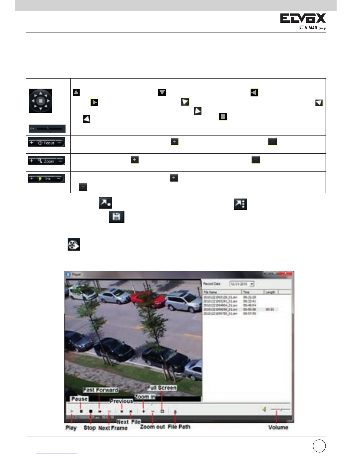
4.2 Riproduzione
Fare clic sull'icona
per visualizzare questa nestra:
Dopo aver selezionato la data di registrazione, i le registrati vengono visualizzati nella casella di elenco dei le registrati. Fare doppio clic
su un le registrato per riprodurlo o controllarlo. Quindi fare clic sul pulsante Play (Riproduci) per riprodurlo.
to rotate the dome upwardsͺ to rotate the dome downwards;
to rotate the dome towards left; to rotate the dome towards
rightͺ
to rotate the dome diagonally up -left;ͺ to rotate the
dome diagonally up-right;
to rotate the dome diagonally down -
left;
to rotate the dome diagonally down -right; to stop
Focus button. Click
button to have long focus and click to
have short focus so that you can adjust the image clearly.
Zoom button. Click
to zoom in the image; click to zoom out
the image.
Iris button. Click
to increase light of the dome; click to
decrease light of the dome.
I
Page 11
9
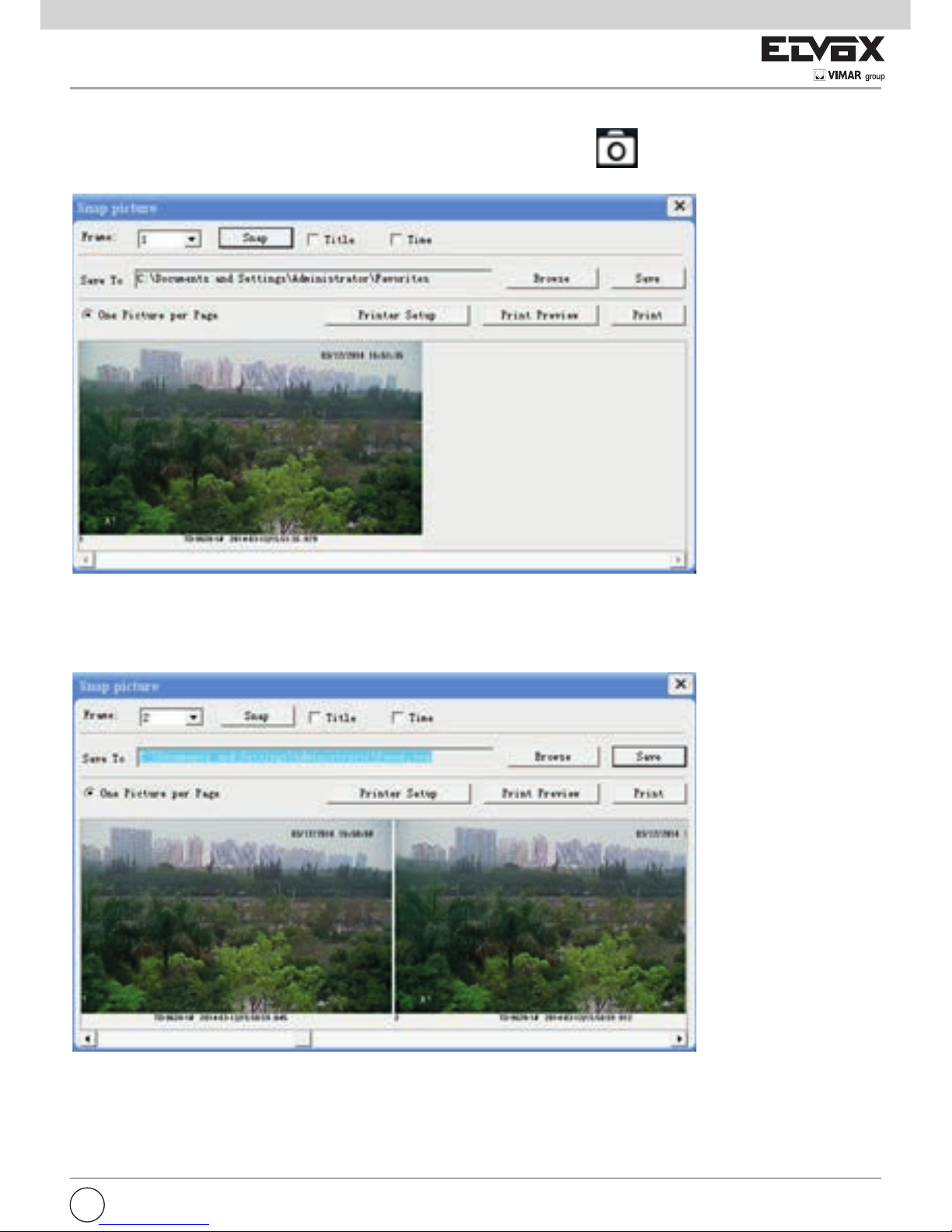
4.3 Istantanea
Selezionare il numero dell'immagine quindi fare clic sull'icona "Snap" (Istantanea) come mostrato di seguito:
Per acquisire più immagini:
1 - Selezionare il numero di immagini dall'elenco a discesa, ad esempio 2.
2 - Selezionare "Title" (Titolo) e "Time" (Ora) per visualizzare il titolo e l'ora delle immagini acquisite contemporaneamente.
3 - Fare clic su "Browse" (Sfoglia) per impostare il percorso, quindi fare clic su "Save" (Salva) per salvare le immagini sull'HDD
del computer. Fare clic su "Print Setup" (Imposta stampante) per aggiungere la stampante e stampare le istantanee.
4 - Fare clic sul pulsante "Snap" (Istantanea) per scattare le foto.
5 - Trascinare la barra di scorrimento per visualizzare tutte le istantanee.
I
Page 12

10
Capitolo 5 Congurazione remota
Le funzioni di congurazione remota includono: System Conguration (Congurazione del sistema), Video Conguration (Congurazione video), PTZ Conguration (Congurazione PTZ), Alarm Conguration (Congurazione allarme), Network Conguration (Congurazione rete) e Advanced Conguration (Congurazione avanzata). Selezionare prima il menu a sinistra quindi
impostare i parametri relativi. Quando un utente congura i parametri di un determinato dispositivo, gli altri utenti non possono
impostare lo stesso dispositivo.
5.1 Congurazione del sistema
Il menu System Conguration include tre sottomenu: Basic Information (Informazioni di base), Date & Time (Data e ora) e SD
Card (Scheda SD).
5.1.1 Informazioni di base
Nell'interfaccia Basic Information è possibile impostare il nome del dispositivo e controllare le relative informazioni del server.
Procedura di impostazione:
1. Fare clic sull'icona "Cong" per visualizzare l'elenco dei menu.
2. Fare clic su "Basic Information" per visualizzare la nestra illustrata di seguito:
Parametro Signicato
Software version (Versione Software) Il software del dispositivo
Software build date (Data versione del software) La data della versione del sotware del dispositivo
Kernel version (Versione kernel) Versione del kernel del dispositivo
Hardware version (Versione hardware) Versione hardware del dispositivo
Mac Address (Indirizzo MAC) Indirizzo MAC del dispositivo
Device name (Nome dispositivo) Il nome del dispositivo
Maximum number of user (Numero massimo
utenti)
Supporta l'accesso di 6 utenti al massimo
6.1.2 Congurazione data e ora
Procedura di impostazione:
1. Andare a System Conguration
Date & Time.
I
Page 13

11
2. Selezionare "Modify Time" (Modica ora) per la denizione automatica dell'ora. Selezionare "Time Zone" (Fuso orario) in base alla
propria posizione.
3. Attivare DST e impostare ora e modo DST.
4. Selezionare "Synchronize with NTP Server" (Sincronizza con il server NTP) per impostare l'ora.
5. Premere il pulsante "Save" per salvare le impostazioni.
5.1.3 Scheda SD
Procedura di impostazione:
1. Andare a System Conguration SD Card come illustrato di seguito:
La prima volta che si utilizza la scheda SD, fare clic su "Format SD card" (Formatta scheda SD).
Fare clic su "Eject card" (Espelli scheda) per non scrivere più dati sulla scheda SD. La scheda SD verrà espulsa in modo sicuro.
Nota: l'utilizzo della funzione scheda SD dovrebbe essere coordinato con l'allarme di movimento.
Quando l'allarme viene attivato, il sistema scatta automaticamente un'istantanea e salva l'immagine nella scheda SD.
5.2 Congurazione video
La congurazione della telecamera include tre sottomenu: Camera Conguration (Congurazione telecamera), Video Stream (Flusso
video), OSD Conguration (Congurazione OSD) e ROI Conguration (Congurazione ROI).
5.2.1 Congurazione telecamera
Procedura di impostazione:
1. Andare all'interfaccia Video Conguration Camera come illustrato di seguito:
I
Page 14

12
2. Regolare Brightness (Luminosità), Contrast (Contrasto), Hue (Toni) e Saturation (Saturazione) dell'immagine.
3. Selezionare il modo di bilanciamento del bianco.
4. È possibile regolare il livello di nitidezza, eliminazione del rumore e frequenza.
5. Attivare la funzione mirror immagine e ip immagine.
6. Premere il pulsante "Save" per salvare le impostazioni.
5.2.2 Flusso video
Andare a Video conguration Video Stream per visualizzare l'interfaccia illustrata di seguito:
In questa interfaccia è possibile impostare risoluzione, frame rate, bit rate, tipo e qualità video e altro ancora a seconda della
larghezza di banda della rete.
5.2.3 Attivazione ingresso allarme
1. Andare a Alarm Conguration
Alarm Input Trigger per visualizzare la scheda illustrata di seguito:
I
Page 15

13
2. Selezionare il sensore nell'elenco a discesa "Sensor" e impostare il nome sensore e tipo di allarme: NO (Normalmente aperto) e NC
(Normalmente chiuso).
3. Attivare l'allarme e selezionare il tempo di durata dell'allarme.
4. Impostare le opzioni di attivazione allarme. La procedura di impostazione è analoga a quella di impostazione dell'attivazione per
rilevamento movimento. Fare riferimento al capitolo sull'attivazione per rilevamento movimento per i dettagli.
5. Per applicare le impostazioni a tutti fare clic sul pulsante "Copy" (Copia) che consente di impostare rapidamente le stesse opzioni
per tutti i sensori.
5.2.4 Programmazione ingresso allarme
Andare a Alarm Conguration Alarm Input Schedule come illustrato di seguito.
I
Page 16

14
1. Selezionare il sensore nell'elenco a discesa "Sensor".
2. La seguente procedura è analoga alla programmazione del rilevamento movimento. Fare riferimento al capitolo Programmazione
rilevamento movimento per ulteriori dettagli.
5.2.5 Uscita allarme
1. Andare a Alarm Conguration Alarm output come illustrato di seguito:
2. Selezionare il tempo di durata dell'allarme e il nome dell'allarme nell'elenco a discesa "Alarm holding time" e "Alarm out" rispettivamente.
3. Premere il pulsante "Save" per salvare le impostazioni.
5.3 Congurazione di rete
La congurazione della rete include nove sottomenu: Port (Porta), IP Address (Indirizzo IP), Server Conguration (Congurazione server), IP
Notify (Notica IP), DDNS Cong (Congura DDNS), RTSP, UPNP, Mail Cong (Congurazione posta) e FTP Setting (Impostazione FTP).
5.3.1 Porta
1. Andare a Network conguration Port per visualizzare l'interfaccia illustrata di seguito:
2. Inserire il numero di porta per l'accesso a Internet Explorer nella casella di testo "HTTP Port".
3. Inserire il numero di porta per la trasmissione audio e video nella casella di testo "Data Port" (Porta dati).
5.3.2 Indirizzo IP
1. Andare a Network Conguration IP Address per visualizzare la scheda illustrata sotto.
I
Page 17

15
2. Per IP setup (Impostazione IP) sono disponibili due opzioni: Obtain an IP address auto by DHCP protocol (Ottieni indirizzo IP
automaticamente da protocollo DHCP) e Use the following IP address (Utilizza questo indirizzo IP), scegliere l'opzione in base alle
proprie esigenze.
3. Use the following IP address: visualizza l'indirizzo IP, la subnet mask, il gateway e il DNS del dispositivo.
4. PPPOE: inserire manualmente il nome utente e la password per l'accesso dial-up Internet.
Eseguire prima il login dei client Internet Explorer, inserire nome utente e password del PPPoE, salvare l'impostazione e uscire. Quindi
impostare la notica di modica dell'indirizzo IP. Il dispositivo eseguirà automaticamente l'accesso dial-up Internet.
5. Premere il pulsante "Save" per salvare le impostazioni.
Capitolo 7 Ricerca video
Fare clic sull'icona "Picture" (Immagine) e cercare nelle immagini salvate nella scheda SD.
1. Impostare l'ora: selezionare la data in "calendar" (calendario) e scegliere l'ora di inizio e l'ora di ne.
2. Scegliere l'evento "Motion" (Movimento) o "Sensor" (Sensore)
3. Fare clic sul pulsante "Search" (Cerca) per cercare l'immagine.
4. Fare doppio clic su un nome le o selezionare un nome le, quindi fare clic sul pulsante "View" (Visualizza) nella casella di
elenco per visualizzare le immagini acquisite.
I
Page 18

16
Elemento Pulsanti Spiegazioni
1
Close (Chiudi): selezionare un'immagine e fare clic su questo pulsante per chiuderla.
2
Close all (Chiudi tutto): fare clic su questo pulsante per chiudere la visualizzazione
delle immagini.
3
Save (Salva): fare clic su questo pulsante per selezionare il percorso in cui salvare
il le di immagine corrente sul PC.
4
Save All (Salva tutti): fare clic su questo pulsante per selezionare il percorso in cui
salvare tutti i le di immagine sul PC.
5
Fit size (Adatta dimensione): fare clic su questo pulsante per adattare l'immagine
alle dimensioni dello schermo.
6
Actual size (Grandezza reale) fare clic su questo pulsante per visualizzare l'immagi-
ne nella grandezza reale.
7
Zoom in (Zoom avanti): fare clic su questo pulsante per ingrandire l'immagine.
8
Zoom out (Zoom indietro) fare clic su questo pulsante per eseguire lo zoom indietro
sull'immagine.
9
Slide play (Presentazione): fare clic su questo pulsante per riprodurre le immagini in
modalità presentazione.
10
Stop: fare clic su questo pulsante per interrompere la presentazione.
11
Velocità di riproduzione: velocità di riproduzione della presentazione
I
Page 19

17
EN
Chapter 1 Introduction
1.1 Overview
This IP speed dome camera is front-end equipment used for video capture. Its digital ip technology makes omni-directional and
non-blind-spot monitoring into reality. It utilizes most advanced technologies, such as video encoding and decoding technology, and complies with the TCP/IP protocol, SoC., etc, to ensure this system more stable and reliable. This unit consists of two
parts: the IP-CAM device and central management software (short for CVM ELVOX). This CVM ELVOX centralizes all devices
together via internet or LAN and establishes a sound surveillance system to realize unied management and remote operation
to all devices in one network.
This product is widely used in banks, telecommunication systems, electricity power departments, law systems, factories, storehouses, uptowns, etc. In addition, it is also an ideal choice for surveillance sites with middle or high risks.
1.2 Interfaces and Parts
1
2
3
4
5
6
8
7
10
1 LAN 2 HP Audio Out 3 MIC In
4 CVBS Video Out 5 Alarm In/Alarm Out 6 RS485
7 Power 8 Safety Wire 9 Base Tray
10 Wiper
Page 20

18
Chapter 2 Installation & Connection
2.1 Install TF Card and Power Connection
Install Storage Card:
1 - Loosen the xed screws of the cabin as shown below.
2 - Insert the TF card into the storage card slot.
3 - Install back the cabin and x it with the xed screws.
1
2
3
4
5
6
8
9
7
10
2.2 Connection
PTZ Art. 46235.020 can handle up to No. 7 inputs and 1 alarm output, with direct connection to the alarm contacts of PTZ,
according to the diagram of Fig. 1 and 2.
EN
1
2
3
4
5
6
8
9
7
10
Computer
Router
NetworkCable
NetworkCable
N
e
t
w
o
r
k
C
a
b
l
e
NetworkCable
Internet
Sensor / Alarm
N
e
t
w
o
r
k
C
a
b
l
e
AC24V A
AC24V B
Earth
1
2
3
4
5
6
8
9
7
10
Description Color
Alarm-IN1 Purple
Alarm-IN2 Grey
Alarm-IN3 White
Alarm-IN4 Pink
Alarm-IN5 Red
Alarm-IN6 Black
Alarm-IN7 Brown
Alarm-n-COM Orange/Black
Alarm-OUT + Yellow/Black
Alarm-OUT - Green/Black
Description Color
RS485TA Yellow
RS485TA Orange
Fig. 1
Contacts N.O.
-
+
5-12 Vdc
-
+
5-12 Vdc
Page 21

19
EN
In case of using the PTZ with NVR, you can only use the alarm No. 1 (see Fig. 3).
1
2
3
4
5
6
8
9
7
10
Computer
Router
NetworkCable
NetworkCable
N
e
t
w
o
r
k
C
a
b
l
e
NetworkCable
Internet
Sensor / Alarm
N
e
t
w
o
r
k
C
a
b
l
e
Fig. 2
Contacts N.O.
-
+
5-12 Vdc
Fig. 3
1
2
3
4
5
6
8
9
7
10
Description Color
Alarm-IN1 Purple
Alarm-IN2 Grey
Alarm-IN3 White
Alarm-IN4 Pink
Alarm-IN5 Red
Alarm-IN6 Black
Alarm-IN7 Brown
Alarm-n-COM Orange/Black
Alarm-OUT + Yellow/Black
Alarm-OUT - Green/Black
Description Color
RS485TA Yellow
RS485TA Orange
Page 22

20
Alarm Output:
a) Supports 1 CH alarm output including OPEN and COM connections.
b) Options: OFF, IN1. If the OFF is selected, no alarm can be output. If IN1 are selected, the alarm can be output only when the
corresponding alarm input triggers the alarm.
c) One passive switch for user to connect alarm devices.
- RS485 Connection
You can connect keyboard to control the speed dome through the RS485 interface.
2.3 Install CVM ELVOX
Find CVM ELVOX software from CD and then double click “Setup.exe” le to pop up installation wizard. Install the software
according to the prompts in the wizard. After you complete the installation, you will see the CVM ELVOX and IP-Tool icon on the
desktop. Please see the user manual of this software for more details.
If you need to install IP-Tool separately, please double click IP-Tool installation package and install it according its wizard prompts. After you nish installing, double click IP-Tool icon to start IP-Tool.
Chapter 3 IE Remote Access
You may connect IP-Cam via LAN or WAN. Here only take IE browser (6.0) for example. The details are as follows:
3.1 LAN
In LAN, there are two ways to access IP-Cam: 1. access through IP-Tool; 2. directly access through IE browser.
3.1.1 Access through IP-Tool
1 - Make sure the PC and IP-Cam are connected to the LAN and the IP-Tool is installed in the PC from the CD.
2 - Double click the IP-Tool icon on the desktop to run this software as shown below:
3 - Modify the IP address. The default IP address of this camera is 192.168.226.201. Click the information of the camera listed
in the above table to show the network information on the right hand. Modify the IP address and gateway of the camera and
make sure its network address is in the same local network segment as the computer’s. Please modify the IP address of
your device according to the practical situation.
EN
- Alarm Connection
Alarm Input:
a) There are seven independent alarm input ports (ALARM-IN1~7) and one grounding port (ALM-GND).
b) There are three alarm input status: “OFF/NC/NO”. If “OFF” is selected, the system will not check the status of the ALM-IN and
ALM-GND. If “NO” is selected, connect DC 5V~DC12V voltage between the alarm input port ALM-IN and the grounding port
(ALM-GND) to trigger the alarm (see Fig. 1). If “NC” is selected, disconnect the voltage between alarm input ports (ALM-IN)
and grounding port (ALM-GND) to trigger the alarm.
Page 23

21
For example, the IP address of your computer is 192.168.13.4. So the IP address of the camera shall be changed to 192.168.13.X.
After modication, please input the password of the administrator and click “Modify” button to modify the setting.
The default password of the administrator is “123456”.
4 - Double click the IP address and then the system will pop up the IE browser to connect IP-CAM. IE browser will auto download
the Active X control. After downloading, a login window will pop up as shown below.
Input the username and password to log in.
The default username is “admin”; the default password is “123456”.
3.1.2 Directly Access through IE
The default network settings are as shown below:
IP address: 192.168.226.201
Subnet Mask: 255.255.255.0
Gateway: 192.168.226.1
HTTP: 80
Data port: 9008
You may use the above default settings when you log in the camera for the rst time.
1 - Manually set the IP address of the PC and the network segment should be as the same as the default settings of the IP camera. Open the network and share center. Click “Local Area Connection” to pop up the following window.
EN
Page 24

22
Select “Property” and then select internet protocol according to the actual situation (for example: IPV4). Next, click “Property”
button to set the network of the PC.
2 - Open the IE browser and input the default address of IP-CAM and conrm. The IE browser will download Active X control
automatically.
3 - After downloading Active X control, the login dialog box will pop up.
4 - Input the default username and password and then enter to view.
3.2 WAN
Take access the camera by the router or virtual server for example:
1 - Make sure the camera is well connected via LAN and then log in the camera via LAN and go to the Cong Network
Cong Port menu to set up the port number.
EN
Page 25

23
2 - Go to Cong Network Cong IP Address menu to modify the IP address.
3 - Go to the router’s management interface through IE browser to forward the IP address and port of the camera in the “Virtual
Server”.
4 - Open the IE browser and input its WAN IP and http port to access.
Port Setup IP Setup
Router Setup
EN
Page 26

24
Chapter 4 Remote Preview
4.1 Remote Preview
After you log in, you will see the following window.
The descriptions of the icon on the remote preview interface:
Icon Description Icon Description
Motion alarm indicator icon
Sensor alarm indicator icon
Fix size
Start/Stop record
Actual size
Playback
Zoom in
Snap
Zoom out
Talk
Full screen
Open/close audio
Move the cursor to view the live image in all directions after you click this button. Additionally,
hold and drag the left mouse button to zoom in the live image.
Right click mouse to appear a pull-down list:
Stream: Four streams are optional.
Turn off the live: Click this item to close the current live preview.
Enable audio: Enable remote audio transmission.
EN
Page 27

25
Full screen: To open full screen display. Double click or click right mouse to return to the previous interface.
Online user: To display the number of the online users accessing the device.
System information: Display the device information.
Click PTZ extended button to unfold PTZ control panel. In remote preview interface, you can view the image from every direction
by controlling PTZ panel.
The descriptions of the control panel are as follows:
Icon Description
to rotate the dome upwardsͺ to rotate the dome downwards;
to rotate the dome towards left; to rotate the dome towards
to rotate the dome upwardsͺ to rotate the dome downwards;
to rotate the dome upwards;
to rotate the dome downwards;
to rotate the dome upwardsͺ to rotate the dome downwards;
to rotate the dome
towards left
; to rotate the dome towards right
to rotate the dome diagonally up-left;
to
rotate the dome diagonally up-right;
to rotate the dome diagonally down-left;
to rotate the dome diagonally up -left;ͺ to rotate the
to rotate the
dome diagonally down-right;
to stop rotating the dome.
to rotate the dome upwardsͺ to rotate the dome downwards;
to rotate the dome towards left; to rotate the dome towards
rightͺ
to rotate the dome diagonally up -left;ͺ to rotate the
dome diagonally up-right;
to rotate the dome diagonally down -
left;
to rotate the dome diagonally down -right; to stop
Drag the scroll bar to adjust rotating speed of the dome.
to rotate the dome upwardsͺ to rotate the dome downwards;
to rotate the dome towards left; to rotate the dome towards
rightͺ
to rotate the dome diagonally up -left;ͺ to rotate the
dome diagonally up-right;
to rotate the dome diagonally down -
left;
to rotate the dome diagonally down -right; to stop
Focus button. Click
button to have long focus and click to
Focus button. Click
to rotate the dome diagonally down -
button to have long focus and click
to have short focus so that you
can adjust the image clearly.
to rotate the dome upwardsͺ to rotate the dome downwards;
to rotate the dome towards left; to rotate the dome towards
rightͺ
to rotate the dome diagonally up -left;ͺ to rotate the
dome diagonally up-right;
to rotate the dome diagonally down -
left;
to rotate the dome diagonally down -right; to stop
Focus button. Click
button to have long focus and click to
have short focus so that you can adjust the image clearly.
Zoom button. Click
to zoom in the image; click to zoom out
Zoom button. Click
to rotate the dome diagonally down -
to zoom in the image; click
to zoom out the image.
to rotate the dome upwardsͺ to rotate the dome downwards;
to rotate the dome towards left; to rotate the dome towards
rightͺ
to rotate the dome diagonally up -left;ͺ to rotate the
dome diagonally up-right;
to rotate the dome diagonally down -
left;
to rotate the dome diagonally down -right; to stop
Focus button. Click
button to have long focus and click to
have short focus so that you can adjust the image clearly.
Zoom button. Click
to zoom in the image; click to zoom out
the image.
Iris button. Click
to increase light of the dome; click to
Iris button. Click
to rotate the dome diagonally down -
to increase light of the dome; click
to decrease light of the dome.
Select preset and click
to rotate the dome diagonally down -
button to have long focus and click to
to zoom in the image; click to zoom out
to increase light of the dome; click to
to go to the preset; select cruise and click
to rotate the dome diagonally down -
button to have long focus and click to
to zoom in the image; click to zoom out
to increase light of the dome; click to
to start cruise. Select and set the preset and then
click
to rotate the dome diagonally down -
to save the position of the preset.
4.2 Playback
Click
icon to see the following window:
After selecting the record date, the record les will be displayed in the record le list box. Double click a certain record le to
playback or check a certain le. Then click Play button to play.
to rotate the dome upwardsͺ to rotate the dome downwards;
to rotate the dome towards left; to rotate the dome towards
rightͺ
to rotate the dome diagonally up -left;ͺ to rotate the
dome diagonally up-right;
to rotate the dome diagonally down -
left;
to rotate the dome diagonally down -right; to stop
Focus button. Click
button to have long focus and click to
have short focus so that you can adjust the image clearly.
Zoom button. Click
to zoom in the image; click to zoom out
the image.
Iris button. Click
to increase light of the dome; click to
decrease light of the dome.
EN
Page 28

26
4.3 Snap
Select the picture number and then click “Snap” icon as shown below:
To capture multiple pictures:
1 - Select the picture number from frame pull down list box, such as 2.
2 - Check “Title” and “Time” to show capture title and time on the captured pictures simultaneously.
3 - Click “Browse” to set saving path and then click “Save” to save pictures to HDD on the computer; Click “Print Setup” to add
the printer and print the snapped pictures.
4 - Click “Snap” button to take snapshots.
5 - Drag the scroll bar to view all snapped pictures.
EN
Page 29

27
Chapter 5 Remote Conguration
Functions of remote congurations include: System Conguration, Video Conguration, PTZ Conguration, Alarm Conguration,
Network Conguration and Advanced Conguration. You should rstly select the menu on the left, and then setup the relative
parameters. When one user congures parameters of a certain device, other users can not set up this device.
5.1 System Conguration
The “System conguration” includes three sub-menus: Basic Information, Date & Time and SD Card.
5.1.1 Basic Information
In the Basic Information interface, you can set up the device name and check the relative information of the server.
Setting steps:
1. Clicking the “Cong” icon will appear the menu list.
2. Clicking the “Basic Information “will pop up a window as shown below:
Parameter Meaning
Software version The software of the device
Software build date The software build date of the device
Kernel version The kernel version of the device
Hardware version The hardware version of the device
Mac Address MAC address of device
Device name Name of the device
Maximum number of user Support max 6 users to access
5.1.2 Date & Time Conguration
Setting steps:
1. Go to “System Conguration”
“Date & Time”.
EN
Page 30

28
2. Select “Modify Time “ to self-dene time. Choose “Time Zone” according to your location.
3. Enable DST and set DST mode and time.
4. Set the time by selecting the “Synchronize with NTP Server”.
5. Press the “Save” button to save the settings.
5.1.3 SD Card
Setting steps:
1. Go to “System Conguration” “SD Card” as shown below:
The rst time you used the SD card, you should click “Format SD card”.
Click “Eject card” to stop writing data to SD card. Then the SD card can be ejected safely.
Note: Using of SD card function should be coordinated with Motion alarm.
When alarm is triggered, the system will automatically snap picture and save the picture into SD card.
5.2 Video Conguration
Camera Conguration includes three submenus: Camera Conguration, Video Stream and OSD Conguration and ROI Conguration.
5.2.1 Camera Conguration
Setting steps:
1. Go to “Video Conguration” “Camera” interface as shown below:
EN
Page 31

29
2. Adjust Brightness, Contrast, Hue and saturation of the picture.
3. Select white balance mode.
4. Sharpen, denoise, frequency are adjustable.
5. Enable the image mirror and image ap function.
6. Press the “Save” button to save the settings.
5.2.2 Video Stream
Go to “Video conguration” “Video Stream” to see an interface as shown below:
In this interface, you can set up the resolution, frame rate, bitrate type and video quality and so on subject to the network bandwidth.
EN
5.44 Alarm trigger
Enter “Alarm conguration” “Alarm input Trigger” to see a acreen as shown below:
Page 32

30
2. Select the sensor at the “Sensor” pull down list and set the sensor name and alarm type: NO and NC.
3. Enable alarm and select alarm holding time.
4. Set alarm trigger options. The setting steps are the same with that of motion detection trigger. Please refer to motion
detection trigger chapter for details.
5. Apply settings to all by clicking “Copy” button, which can quickly set the same settings for all sensors.
5.4.5 Alarm Input Schedule
Go to “Alarm Conguration” “Alarm Input Schedule” as shown below
EN
Page 33

31
1. Select the sensor at the “Sensor” pull down list.
2. The following setup steps are similar to Motion Detection Schedule’s. Please refer to Motion Detection Schedule chapter for
more details.
5.4.6 Alarm Out
1. Go to “Alarm conguration” ”Alarm out” as shown below:
2. Select alarm holding time and alarm name at the “Alarm out” and “Alarm holding time” pull down list box respectively.
3. Press the “Save” button to save the settings
5.5 Network Conguration
Network conguration includes nine submenus: Port, IP Address, Server Conguration, IP Notify, DDNS Cong, RTSP, UPNP,
Mail Cong and FTP Setting.
5.5.1 Port
1. Go to “Network conguration” ”Port” to see the interface as shown below:
2. Input port number for IE access in the “HTTP Port” textbox.
3. Input the port number for audio & video transmission in the “Data Port” textbox.
5.5.2 IP Address
1. Go to “Network Conguration” ”IP Address” to see a tab shown below:
EN
Page 34

32
2. There are two Options for IP setup: obtain an IP address auto by DHCP protocol and use the following IP address, please
choose one of options for your requirements.
3. Use the following IP address: display the IP address, subnet mask, gateway and DNS of the device.
4. PPPOE: Manual input the user name and password for dial-up internet.
Firstly, Login IE clients, enter user name and password of PPPoE, save the setting and exit. Secondly, set up IP address
change notice. Then the device will dial-up internet automatically.
5. Press the “Save” button to save the settings.
EN
Chapter 6 Video Search
Click “Picture” icon and search the images which saved in the SD card.
1. Set time: Select date in the “calendar” and choose the start and end time.
2. Choose event “Motion” or “Sensor”.
3. Click “Search” button to search the picture.
4. Double click a lename or select a lename and then click “view” button in the list box to view captured pictures.
Page 35

33
Item Buttons Explanations
1
Close: Select certain picture and click this button to close this picture.
2
Close all: Click this button to close all pictures viewing.
3
Save: Click this button to select the save path of the picture le on the PC for saving
the current picture.
4
Save all: Click this button to select the save path of the picture les on PC for saving
all pictures.
5
Fit size: The picture will t on screen by clicking this button.
6
Actual size: Click this button to display the actual size of the picture as required.
7
Zoom in: Click this button to amplify the picture.
8
Zoom out: Click this button to zoom out the picture
9
Slide play: Click this button to play the picture in slide show mode.
10
Stop: Click this button to stop slide show
11
Play speed: Play speed of the slide show
EN
Page 36

Vimar SpA: Viale Vicenza, 14
36063 Marostica VI - Italy
Tel. +39 0424 488 600 - Fax (Italia) 0424 488 188
Fax (Export) 0424 488 709
www.vimar.com
49400750A0 00 15 02
VIMAR - Marostica - Italy
 Loading...