

Page 1
3
2
1
START
SI / YES
STOP
FINE
END
1
PREC.
PREV
2
SUCC.
NEXT
3
OK
3
2
1
1
PREC.
PREV
2
SUCC.
NEXT
3
OK
Installation and operation manual
Video or audio Elvox 2-wire entrance panels with traditional push-buttons
Page 2
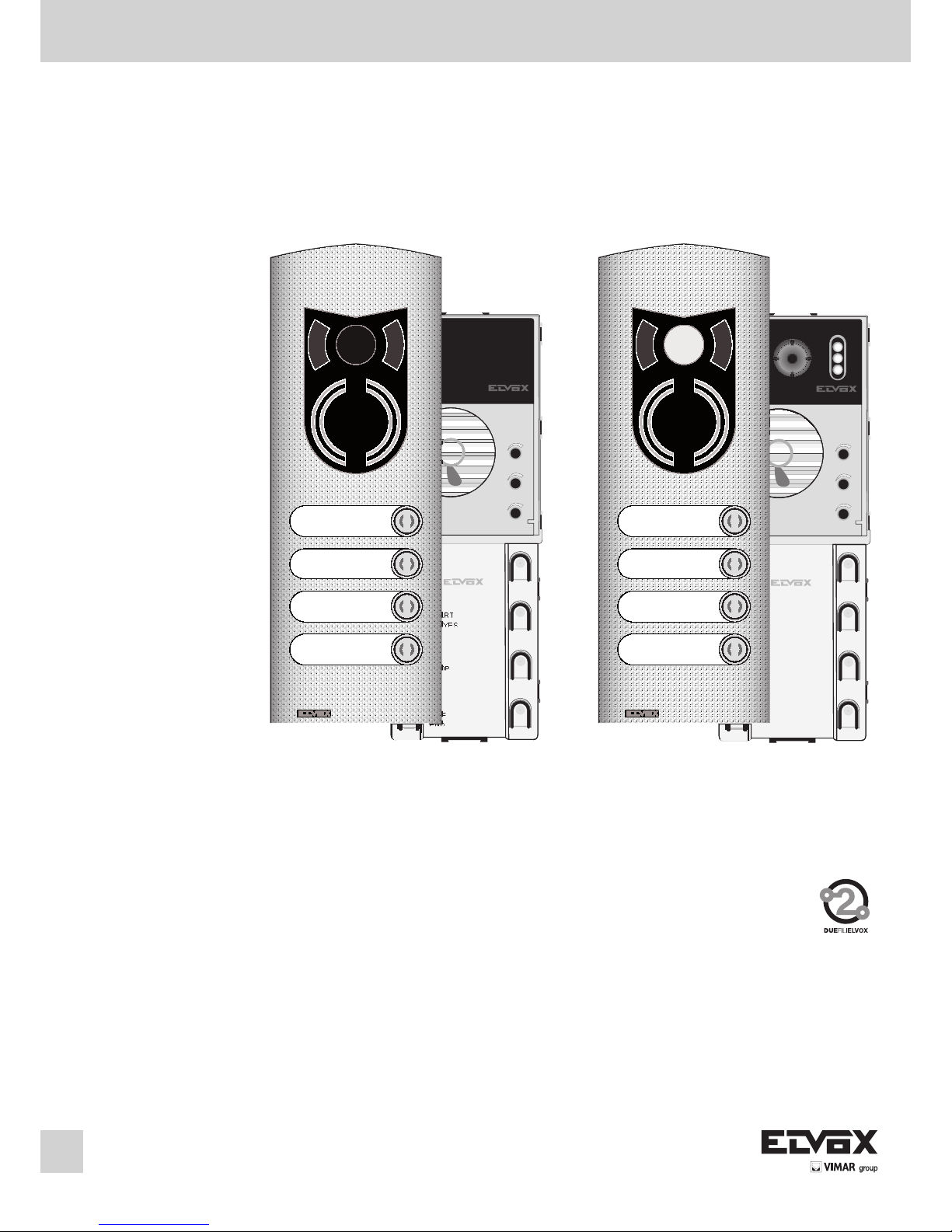
DESCRIPTION
Types 12F3 and 12F5 comprise respectively an electronic base unit for the
assembling of two models of entrance panels.
12F3 audio electronic module with conventional push-buttons (single or
double row)
12F5 video electronic module with colour and conventional push-buttons
(single or double row)
To expand the number of calls, requires installation and subsequent programming of additional modules type 12TS (for entrance panels with push-buttons
in single row, from 5 or more calls) or type 12TD (for push-buttons in double
row, from 9 or more calls), see Fig. 11, 12 on page 8.
The abovementioned electronic units are to be used with plates and
components of the 1200 series, separately sold.
Each push-button in the electronic units can generate different call codes with
values from 1 to 200. The entrance panels are designed to operate either
alone or with other entrance panels. In any event one must be set as a Master entrance panel and the others as Slave.
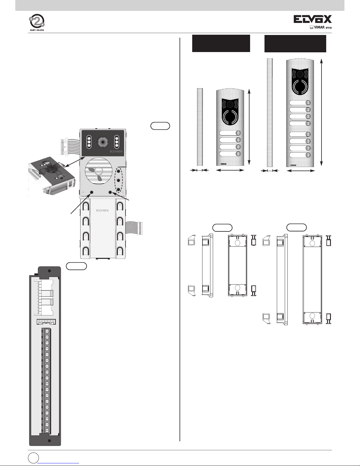
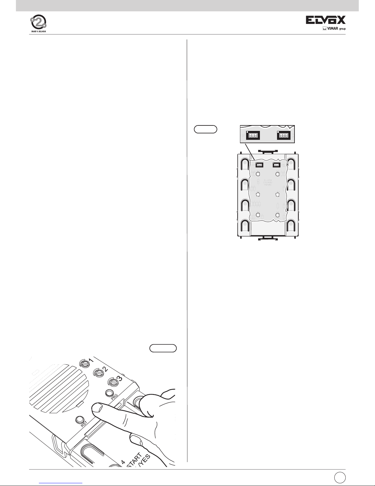
The front of the electronic unit (see Fig. 2, detail A) is fitted with the following
adjustments:
1 Voice line balancing control
2 External volume
3 Internal volume
The entrance panel is equipped with 6 push-buttons for the base programming phase. The base programming of the entrance panel is carried out without installing the front plate, so as to reach all the 6 push-buttons. The
serigraph close to each push-button ease this operation.
For the advanced programming of the entrance panel use the programming
module type 950C or PC Software SaveProg Type 69CD via the interfaces
Type 692I or Type 692I/U.
The volume adjustment may cause the LARSEN effect (whistle); in this event
operate on trimmer 1 (Balance) to avoid the whistle or decrease one or both
volumes (Fig. 2, detail A).
To the audio entrance panels an external camera type CCTV can be connected; in this case it must be programmed as video camera.
The video cameras can be used indifferently either in colour either in B/W installations.
Operating temperature: -10° C ÷ +55° C.
INSTALLATION
The assembling and the installation of the electronic units for the 1200 series
plates require the following phases:
1- Define the plate for the electronic base unit and possible additional plate
(see push-button plates on page: components 4 and 5).
2- Define the back boxes and the frames for the surface wall-mount or
flush-mount installation (see push-button plates on page 6, accessories).
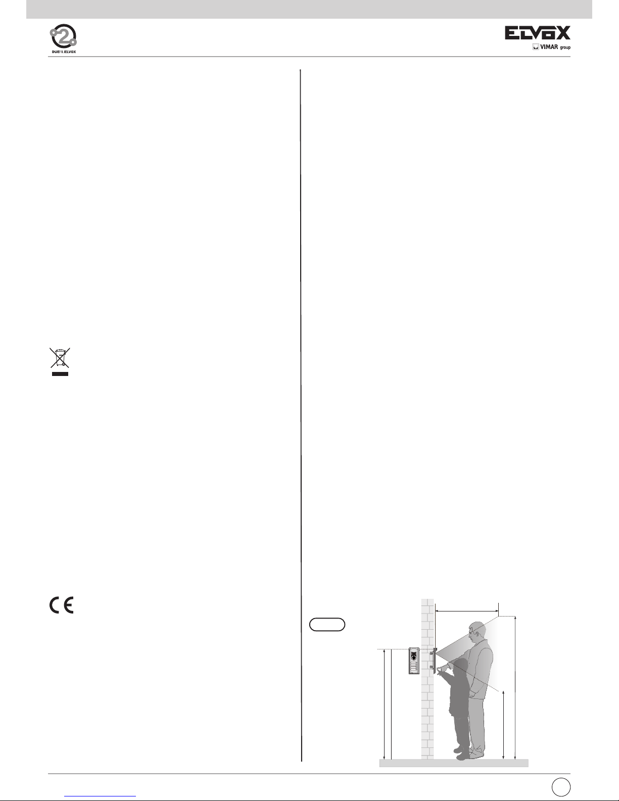
3- Install the flush-mount or surface wall-mount back boxes with the upper
edge at a height of approx. 1,65 m from the ground (Fig. 1).
4- Fix the rainproof covers to the back boxes.
5- Fix the terminal box of the base module to the module holder frame of the
entrance panel.
6- Connect the terminal block to the system as shown in the wiring dia-
gram.
7- Fix the module holder frame.
8- Connect the electronic unit of the base module to the additional modu-
les, if any (extension of the push-button number).
9- Insert the electronic unit and the additional modules in the module hol-
der frames of the entrance panels.
10- Insert the microphone of the electronic base unit in the module holder
frame of the entrance panel (Fig. 9, Part 1).
11- Insert the external plate of the electronic unit in the module holder frame
and the additional entrance panels in the remaining module holder fra-
mes.
12- Close the panel.
2
GB
1,65m
2,04m
1,04m
1m
Fig. 1
SAFETY INSTRUCTIONS FOR INSTALLERS
- Carefully read the instructions on this leaflet: they give important information on the safety, use and maintenance of the installation.
- After removing the packing, check the integrity of the set. Packing
components (plastic bags, expanded polystyrene etc.) are dangerous
for children. Installation must be carried out according to national safety regulations.
- It is convenient to fit close to the supply voltage source a proper bipolar type switch with 3 mm separation (minimum) between contacts.
- Before connecting the set, ensure that the data on the label correspond
to those of the mains.
- Use this set only for the purposes designed, i.e.for electric door-opener systems. Any other use may be dangerous. The manufacturer is
not responsible for damage caused by improper, erroneous or irrational use.
- Before cleaning or maintenance, disconnect the set.
- In case of failure or faulty operation, disconnect the set and do not
open it.
- For repairs apply only to the technical assistance centre authorized by
the manufacturer.
- Safety may be compromised if these instructions are disregarded.
- Do not obstruct opening of ventilation or heat exit slots and do not expose the set to dripping or sprinkling of water.
- Installers must ensure that manuals with the above instructions are left
on connected units after installation, for users' information.
- All items must only be used for the purposes designed.
- The ominipolar switch must be easily accessed.
- WARNING: to avoid the possibility of hurting yourself, this unit must be
fixed to the wall according to the installation instructions.
- This leaflet must always be enclosed with the equipment.
Directive 2002/96/EC (WEEE)
The crossed-out wheelie bin symbol marked on the product indicates that at the end of its useful life, the product must be han-
dled separately from household refuse and must therefore be
assigned to a differentiated collection centre for electrical and electronic
equipment or returned to the dealer upon purchase of a new, equivalent
item of equipment.
The user is responsible for assigning the equipment, at the end of its life,
to the appropriate collection facilities.
Suitable differentiated collection, for the purpose of subsequent recycling
of decommissioned equipment and environmentally compatible treatment and disposal, helps prevent potential negative effects on health and
the environment and promotes the recycling of the materials of which the
product is made. For further details regarding the collection systems available, contact your local waste disposal service or the shop from which
the equipment was purchased.
Risks connected to substances considered as dangerous (WEEE).
According to the WEEE Directive, substances since long usually used on
electric and electronic appliances are considered dangerous for people
and the environment. The adequate differentiated collection for the subsequent dispatch of the appliance for the recycling, treatment and dismantling (compatible with the environment) help to avoid possible
negative effects on the environment and health and promote the recycling of material with which the product is compound.
Product is according to EC Directive 2004/108/EC and following norms.
Page 3
STANDARD MODULES
The standard modules consist of: an electronic unit and a connection terminal block. The electronic unit is equipped with a speech unit, camera (on
video versions), wiring for terminal block connections, wiring for connection of additional modules and 8 call push-buttons, 6 of which are used for
standard programming.
The standard electronic units for colour video panels are equipped with a
camera with the following specifications:
- CCD 1/4" color sensor
- Resolution: 350 linee TV
- Aspheric lens f = 2.7 mm, F = 2.4
- Minimum lighting level 1.0 lux
All cameras can be tilted manually, horizontally and vertically, on removal
of the entrance panel external plate.
Example of standard module with camera.
3
2
1
RST
PRG
4
START
SI / YES
5
STOP
NO
6
FINE
END
1
PREC.
PREV
2
SUCC.
NEXT
3
OK
PRG
CN1) Connector for electronic unit.
CN2) Connector for programmer type 950C.
B2) 2-wire Bus (cable riser).
B1) 2-wire Bus (cable riser).
EXT+) External power supply (+ type 6923).
EXT-) External power supply (- type 6923).
VLED) LED power supply for additional modules.
X) Video input (coaxial core), for external ca-
mera (for type 89F8 only).
M) Video input (coaxial sheath), for external ca-
mera (for type 89F8 only).
PA) Input for door open sensor (with reference to
terminal M).
CA) Door open control (with reference to termi-
nal M).
M) Ground.
S+) 12Vdc lock output (+).
S-) 12Vdc lock output (-).
+12V) +12V output (max 100 mA) with PTC protec-
tion.
-L) External camera pilot, open collector output.
SR) Lock pilot via relay, open collector output.
F2) F2 function pilot via relay, open collector out-
put.
F1) F1 function pilot via relay, open collector out-
put.
M) Ground.
B2
B1
EXT+
EXT-
VLED
M
PA
CA
M
S+
S-
+12V
-L
SR
F2
F1
M
X
B2
B1
EXT+
EXT-
VLED
M
PA
CA
M
S+
S-
+12V
-L
SR
F2
F1
M
X
CN2
CN1
CS2411 250105
Wiring for terminal block
connection
Wiring for connection of additional modules
Controls:
1 - Balance
2 - External volume
3 - Internal volume
Manual horizontal
and vertical tilt
Fig. 3
Reset
)
*
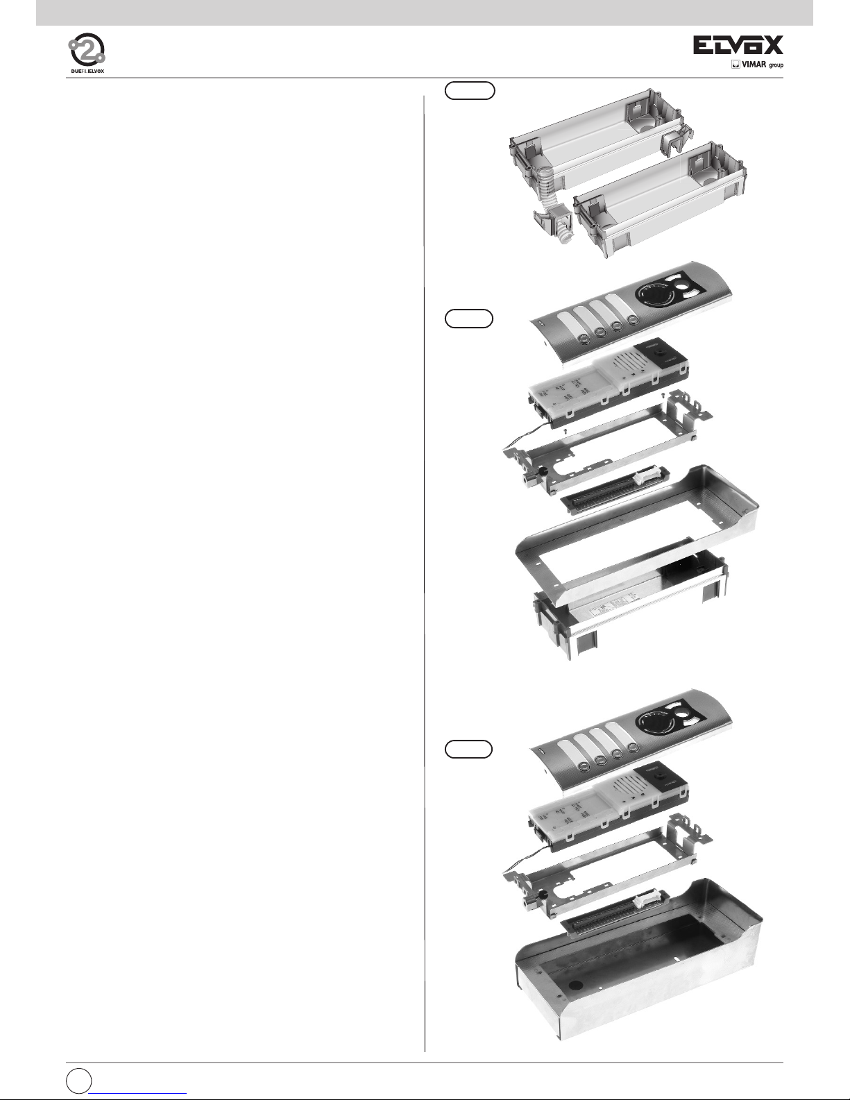
Electronic unit
Fig. 4
Fig. 5
Terminal block
*
The panel supplies a current peak IT> 1A for 10
mS, followed by a hold current I
M
= 200mA for the
entire duration of the lock control (see lock time).
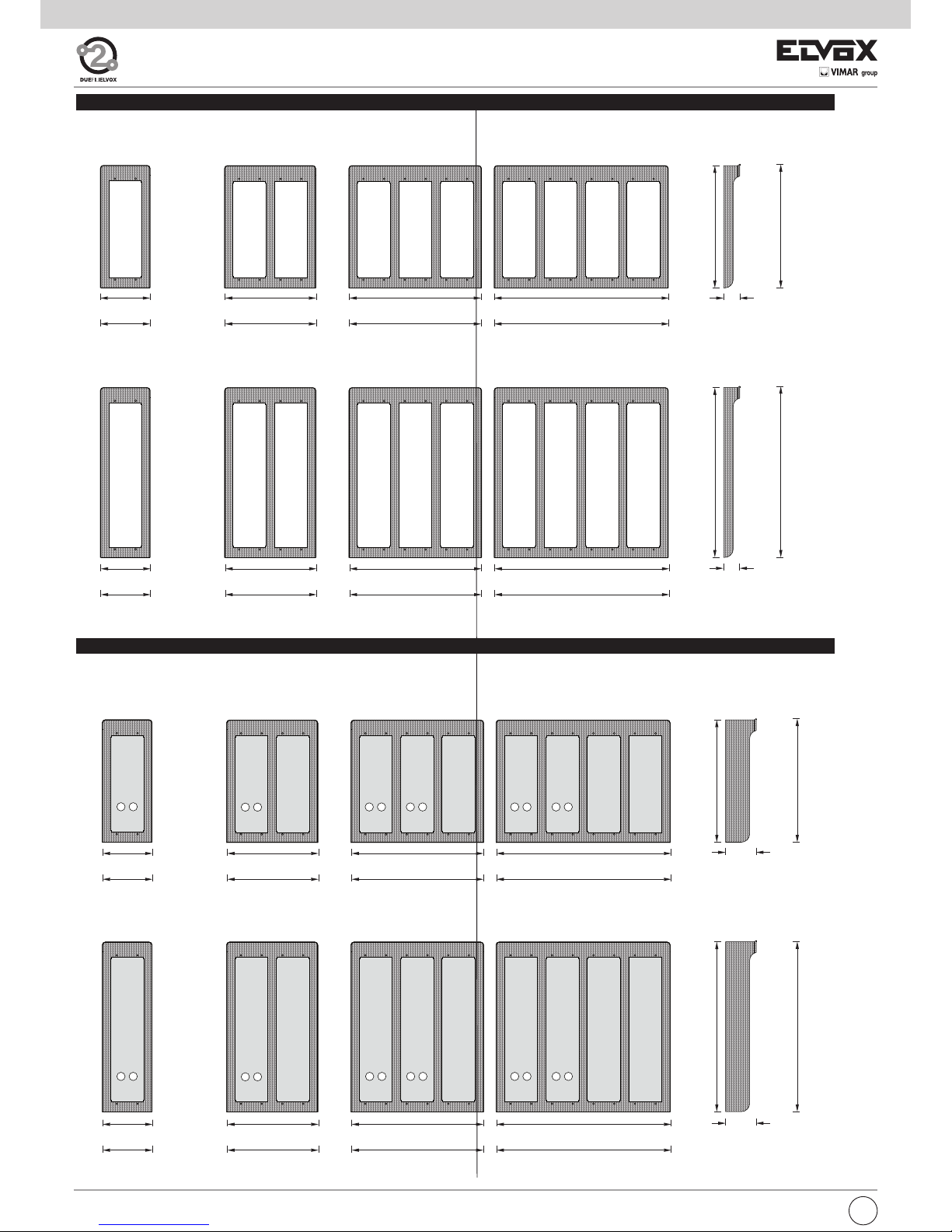
HEIGHT OF 2-MODULE
ENTRANCE PANELS
HEIGHT OF 3-MODULE
ENTRANCE PANELS
Box width 88mm for 1 horizontal module and 50 mm depth.
Type 9092, 9192
For 2 additional modules.
Height: 2 verical modules (248 mm)
Type 9093, 9193
For 3 additional modules.
Height: 3 vertical modules (360 mm)
ACCESSORIES: FLUSH-MOUNTED BACK BOXES
396
100
282
22
100
22
Fig. 2
GB
3
Page 4
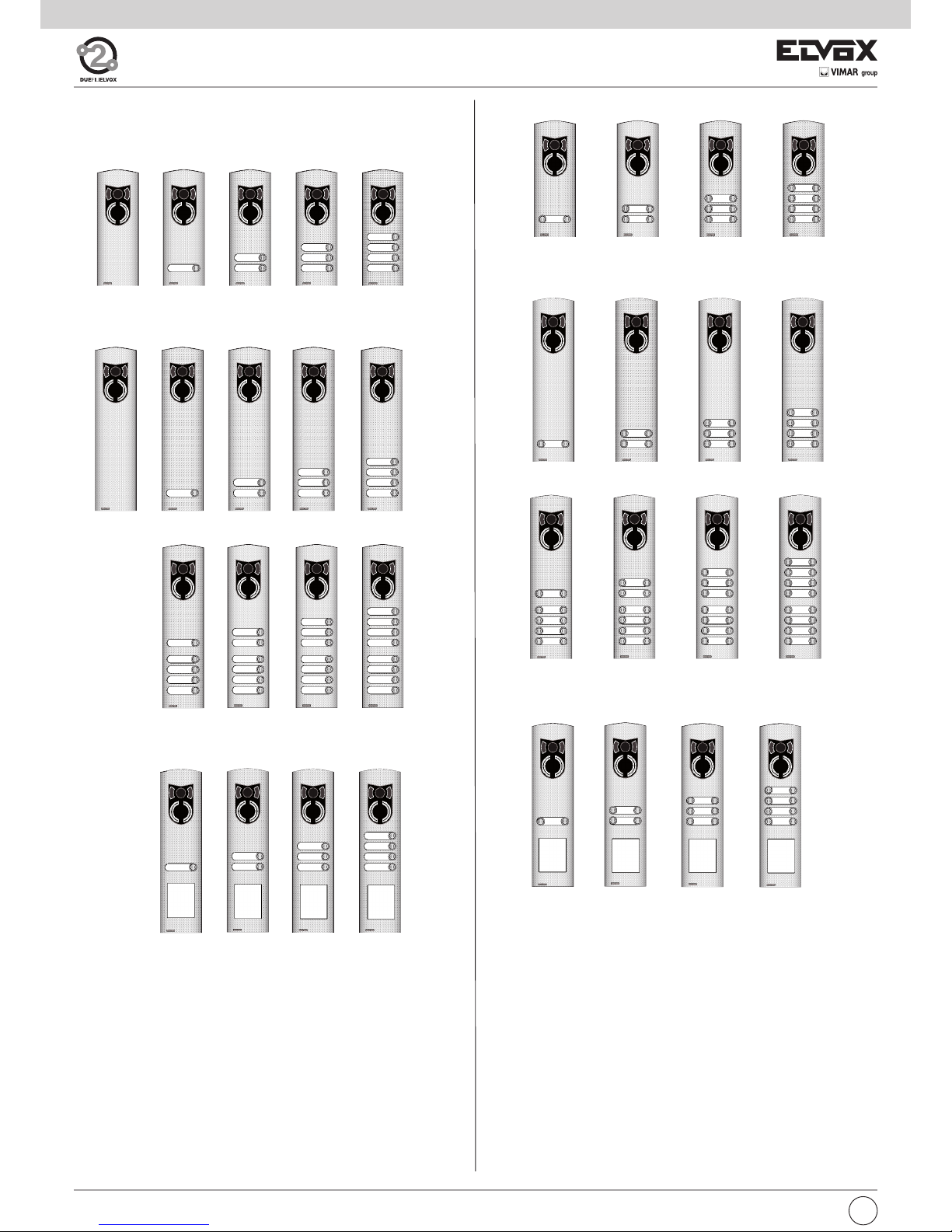
Art. 1222/D
Art. 1224/D
Art. 1226/D
Art. 1228/D
Art. 1232/D Art. 1234/D
Art. 1236/D
Art. 1240/D
Art. 1242/D
Art. 1244/D
Art. 1246/D
Art. 12N2/D
Art. 1238/D
Art. 12N4/D Art. 12N6/D
Art. 12N8/D
Art. 12N1 Art. 12N2 Art. 12N3
Art. 1230 Art. 1231 Art. 1232 Art. 1233 Art. 1234
Art. 1235
Art. 1236
Art. 1237
Art. 1220
Art. 1221 Art. 1222 Art. 1223
Art. 12N4
Art. 1224
Art. 1238
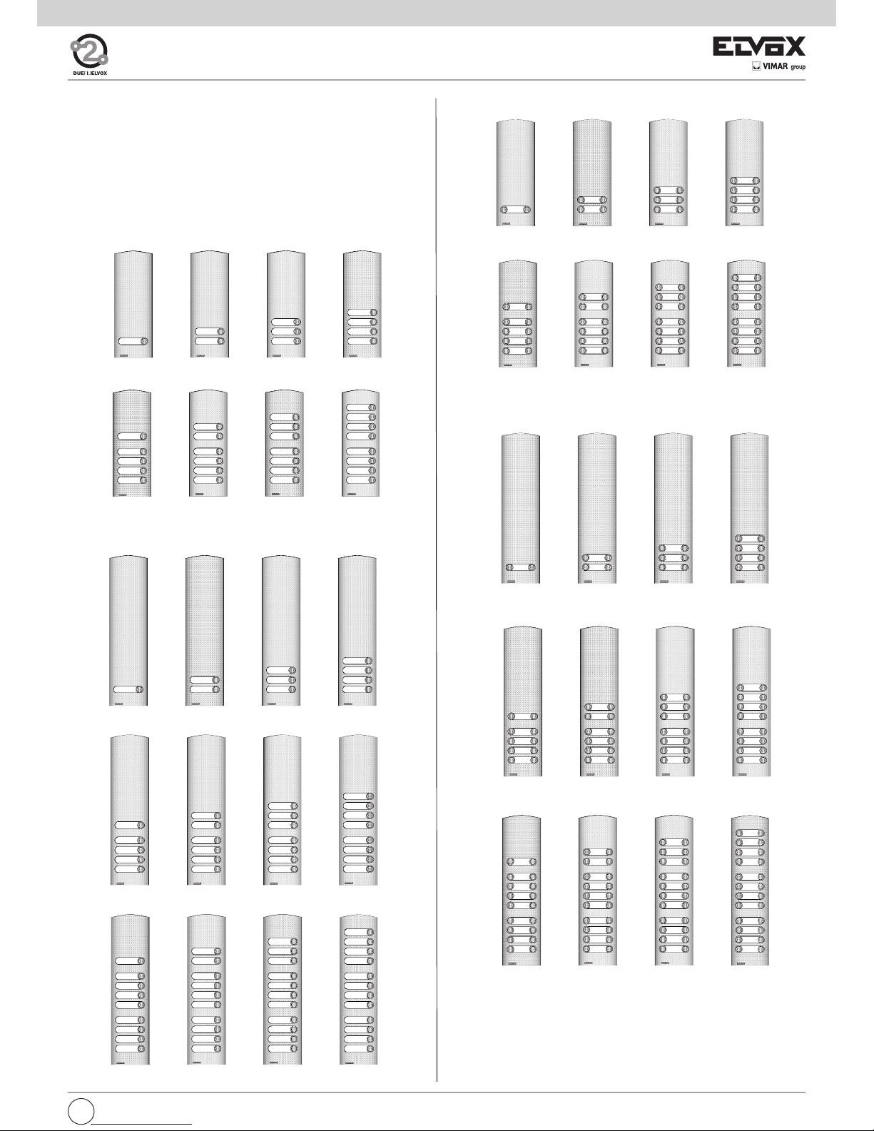
1200 SERIES AUDIO/VIDEO ENTRANCE PANELS
(TWO/THREE MODULES)
- Two-module entrance panels with push-buttons in double row
- Three-module entrance panels with push-buttons in double row
- Three-module entrance panels with push-buttons in double row and
street number holder
- Two-module entrance panels
- Three-module entrance panels
- Three-module entrance panels with street number holder
GB
4
Page 5
ADDITIONAL ENTRANCE PANELS
The additional entrance panels with traditional type push-buttons are connected to the electronic base units type 12F3 and 12F5 to extend the number of push-buttons. Modules type 12TS (for entrance panels with
push-buttons in single row) or type 12TD (for push-buttons in double row),
which are inserted in the frames under the plates, are connected one after
the other by means of the wiring supplied with the modules. They are then
connected to the standard electronic unit by means of the wiring in the
lower section of the unit Fig .2). Modules type 12TS, 12TD are not supplied as standard with the plates.
Art. 1252/D
Art. 1254/D Art. 1256/D
Art. 1258/D
Art. 1280/D
Art. 1282/D
Art. 1284/D
Art. 1286/D
Art. 1262/D
Art. 1264/D Art. 1266/D
Art. 1268/D
Art. 1270/D
Art. 1272/D Art. 1274/D
Art. 1276/D
Art. 1278/D
Art. 1290/D
Art. 1292/D
Art. 1294/D
Art. 1261
Art. 1262 Art. 1263 Art. 1264
Art. 1265 Art. 1266
Art. 1267 Art. 1268
Art. 1269 Art. 1270 Art. 1271
Art. 1272
Art. 1251
Art. 1252 Art. 1253
Art. 1254
Art. 1255
Art. 1256
Art. 1257 Art. 1258
- Two-module additional entrance panels
- Three-module additional entrance panels
- Three-module entrance panels with push-buttons in double row
- Two-module entrance panels with push-buttons in double row
5
GB
Page 6
1P21 1P22 1P23 1P24
for 1 panel for 2 panels for 3 panels for 4 panels
2 modules high alta 2 moduli 2 modules high 2 modules high
RAINPROOF COVERS
1E21 1E22 1E23 1E24
for 1 panel for 2 panels for 3 panels for 4 panels
2 modules high alta 2 moduli 2 modules high 2 modules high
SURFACE-MOUNTED BOXES WITH RAINPROOF COVER
297
39,5
39,5
412
295
410
74
74
297
412
295
410
124 front side 224 front side 324 front side 424 front side
120 rear side 220 rear side 320 rear side 420 rear side
124 front side 224 front side 324 front side 424 front side
120 rear side 220 rear side 320 rear side 420 rear side
124 front side 224 front side 324 front side 424 front side
120 rear side 220 rear side 320 rear side 420 rear side
124 front side 224 front side 324 front side 424 front side
120 rear side 220 rear side 320 rear side 420 rear side
1E31 1E22 1E23 1E24
for 1 panel for 2 panels for 3 panels for 4 panels
3 modules high 3 modules high 3 modules high 3 modules high
1P31 1P32 1P33 1P34
for 1 panel for 2 panels for 3 panels for 4 panels
3 modules high 3 modules high 3 modules high 3 modules high
GB
6
Page 7
FLUSH-MOUNTED ENTRANCE PANEL INSTALLATION WITH RAINPROOF COVERS.
Assembly of flush-mounted entrance panel requires the use of the flushmounted back boxes type 9092 (9192), 9093 (9193) respectively for 2 or
3 electronic modules mounted vertically (Fig. 4 and 5).
If the entrance panel uses more than one flush-mounted back box, the
rainproof covers must also be used (see push-button plates: accessories
on page 4, series 1Pxx), according to the number of modules fitted vertically or horizontally.
Note: Back boxes type 9092 and 9192 or 9093 and 9193 cannot be matched between them but only between: 9092 with 9092, 9192 with 9192 or
9093 with 9093 and 9193 with 9193.
Warning:during installation of back box type9192 it is necessary to insert
the cover sup-plied in order to avoid possible deformationsof the box itself.
Installation:
- If the installation requires a combination of several back boxes, use the
hooks supplied with the back boxes to secure them together (Fig. 6).
- Install the back box with the upper edge at a height of approx. 1,65 m
from the ground (Fig. 1).
- Fix the terminal block of the electronic unit under the module holder frame
by means of the screws supplied (Fig. 7).
- Fix the rainproof cover to the flush-mounted back box using the screws
supplied (Fig. 7).
- Fix the module holder frames to the frames and the back boxes (Fig. 7).
- Connect the terminal box of the electronic unit to the system.
- Connect the electronic unit to the terminal block by means of the wiring
on the upper section
(Fig. 2).
- Connect the additional entrance panels (Fig. 11), if any.
The connection of more additional modules may require an additional power supply Type 6582 for the LED supply voltage.
- Insert the electronic unit and the additional modules in the module holder frames. Use the separator supplied with the additional modules to
keep them joined (Fig. 12).
- Insert the microphone in the lower right section of the module holder
frame (Fig. 9 - part. 1).
Pay attention that the microphone cables are inserted in the external
slot of the electronic module (Fig. 9A, 9B).
- If necessary, remove the white cover of push-buttons, of the electronic
unit and of the additional modules.
- Perform the programming phases.
- Reinsert the push-button protection.
- Close the entrance panel, attaching the plate first from the upper section and then securing the lower section by means of the special key on
the head section.
- To remove the name-tag: Press lightly with the fingers to remove the
name-tag placed on the rear section of the push-button plate (Fig. 10).
SURFACE WALL-MOUNTED ENTRANCE PANEL INSTALLATION
Assembly of the surface wall-mounted entrance panel requires the use
of the back boxes series 1Exx.
Installation:
- Fix the electronic unit terminal block under the module holder frame
by using the screw provided (Fig. 8).
- Fix the module holder frames to the frames and back boxes (Fig. 8).
- Connect the terminal block of the electronic unit to the system.
- Connect the electronic unit to the terminal block by means of the
cable present on the upper section (Fig. 2).
- Connect the additional modules, if any (Fig. 11).
The connection of more additional modules may require an additional power supply Type 6582 for the LED supply voltage.
- Insert the electronic unit and the additional modules in the module
holder frames. Use the separator supplied with the additional modules to keep them joined (Fig. 12).
- Insert the microphone in the right lower side of the module holder
frame (Fig. 9 - part. 1).
Pay attention that the microphone cables are inserted in the external
slot of the electronic module (Fig. 9A, 9B).
- If necessary, remove the white cover of push-buttons, of the electro-
nic unit and of the additional modules.
- Perform the programming phases.
- Reinsert the push-button protection.
- Insert the module plates in the modules holder frames (Fig. 8).
- Close the entrance panel, attaching the plate first from the upper sec-
tion and then securing the lower section by means of the special key
on the head section.
- To remove the name-tag: Press lightly with the fingers to remove the
name-tag placed on the rear section of the push-button plate (Fig.
10).
Fig. 6
Fig. 7
Fig. 8
7
GB
Page 8

Fig. 11
Back
Fig. 12
Type 12F3, Type 12F5 Type 12TS o 12TD
Type 12TS in panels with push-buttons in single row (from 5 or more
calls). Type 12TD in panels with push-buttons in double row (from 9 or
more calls).
Fig. 9
part. 1
Fig. 10
Fig. 9A
Fig. 9B
Microphone cable
Electronic unit with module holder frame
Electronic unit without module holder frame
Microphone cable
3
2
1
RST
PRG
4
START
SI / YES
5
STOP
NO
6
FINE
END
1
PREC.
PREV
2
SUCC.
NEXT
3
OK
GB
8
Page 9
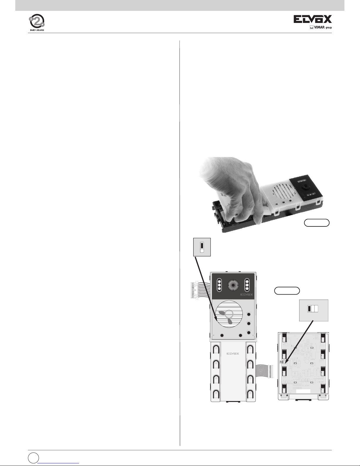
MASTER/SLAVE ASSIGNMENT
(Perform modifications with system switched off)
On systems with more than one panel, a Master panel must be defined
(one only) while the others must be defined as Slave.
This operation is performed by inserting or removing the TP jumper in the
electronic unit below the white cover of the push-buttons. The panel is
supplied as standard with the jumper inserted (Master condition).
Jumper status
TP (inserted) - Master condition.
TP (removed) - Slave condition (to programming)
SV (removed) - always keep without jumper.
SA (inserted) - for audio entrance panels series 12F3
SA (removed) - for video entrance panels 89F5/... or audio
entrance panels 89F3/... but with an
external CCTV camera connected.
Fig. 13A
PATAM ETER S
The panel is supplied already with a standard configuration, to be modified in the case of multiple panels in the same system and if the user wishes to changes the panel operating parameters. There are two parameter
programming levels; one standard and one advanced. Standard programming can be performed directly from the panel keys, while advanced programming requires use of the programmer type 950C or the software
SaveProg Type 69CD for PC by means of interfaces Type 692I or Type
692I/U..
Standard programming parameters:
- Parameter Default value
- Panel ID 1 (Master)
- Reset EEPROM
- Single/Double push-buttons Single row
- Answer time 30 seconds
- Conversation time 120 seconds
- Self-start time 10 seconds
- Lock time 1 second
- F1 time 1 second
- F2 time 1 second
- Panel ringtone repeat Enabled
- Lock block Disabled
- Monitor/interphone ringtone cycles 2
- External volume 15
- Internal volume 3
- Pushbutton remapping Hardware
Parameters for standard and advanced programming with type 950C
or SaveProg:
- Message language Local
- panel ID 1 (Master)
- First key ID 1
- Pushbutton remapping Hardware
- Single/double push-buttons Single row
- Programming password 654321
- Answer time 30 s.
- Conversation time 120 s.
- Self-start time 10 s.
- Lock time 1 s.
- F1 time 1 s.
- F2 time 1 s.
- External volume 15
- Internal volume 3
- Lock block Disabled
- Enablings/Disablings No association
- Panel ringtone repeat Enabled
- Monitor/interphone ringtone cycles 2
- Common locks No association
- F1 common No association
- F2 common No association
- Auto-switching disabling Disabled
- Self-start sequence (Master panel only) No association
- Interphone/Monitor configuration
- Interphone/Monitor function key assignment
- Flag YES / NO
- Function key assignment
o Not Assigned
oIntercommunicating
o Self-Starting
o Auxiliary
o F1 function
o F2 function
o F1 function specific
o F2 function specific
o No Internal Call Ringtone
o No External Call Ringtone
- Call groups (4)
- Associated door call units (4)
- Volume or loudness for 6600 series appliances and derivatives
o Ringtone
o Speakerphone
o External ringtone type
o Brightness (only video door entry units)
o Contrast (only video door entry units)
o Door call ringtone type models Vimar®)
o Intercommunicating ringtone type (only for some models
Vimar®)
- Remote button module configuration.
PRELIMINARY OPERATIONS
Before programming the panels, perform the following preliminary ope-rations:
- Slave panel assignment. On systems with a single panel, this will bedefined Master (default setting). On systems with multiple panels of any
model (alphanumerical, push-buttons), one will be defined Master and
theothers SLAVE.
- Pushbutton hardware programming, for additional modules only.
- Panel ID, entrance panel identification code On systems with multiplepanels, the SLAVE (alphanumerical, push-buttons, outdoor) panels will
be identified with a code.
The panel programming phases use push-buttons on the electronicunit (from 1 to 6); thus performed these operations without closing
thepanel with the front plate.
Fig. 13B
Keep jumper in this position
TP
SV
SA
SV
DL3
DL4
DL5
DL6
1
2
3
4
5
6
SV
TP
SA
3
2
1
RST
PRG
4
START
SI / YES
5
STOP
NO
6
FINE
END
1
PREC.
PREV
2
SUCC.
NEXT
3
OK
9
GB
Page 10
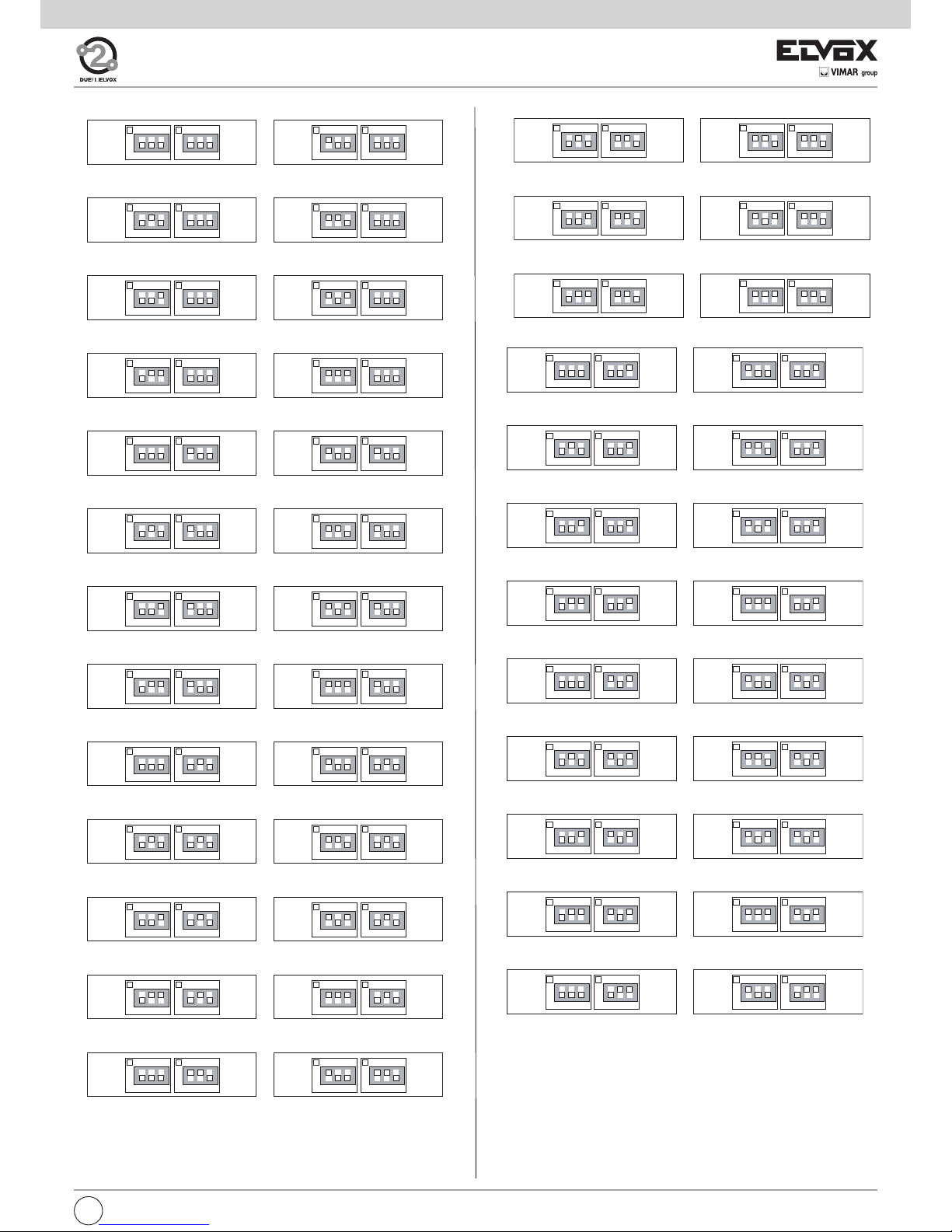
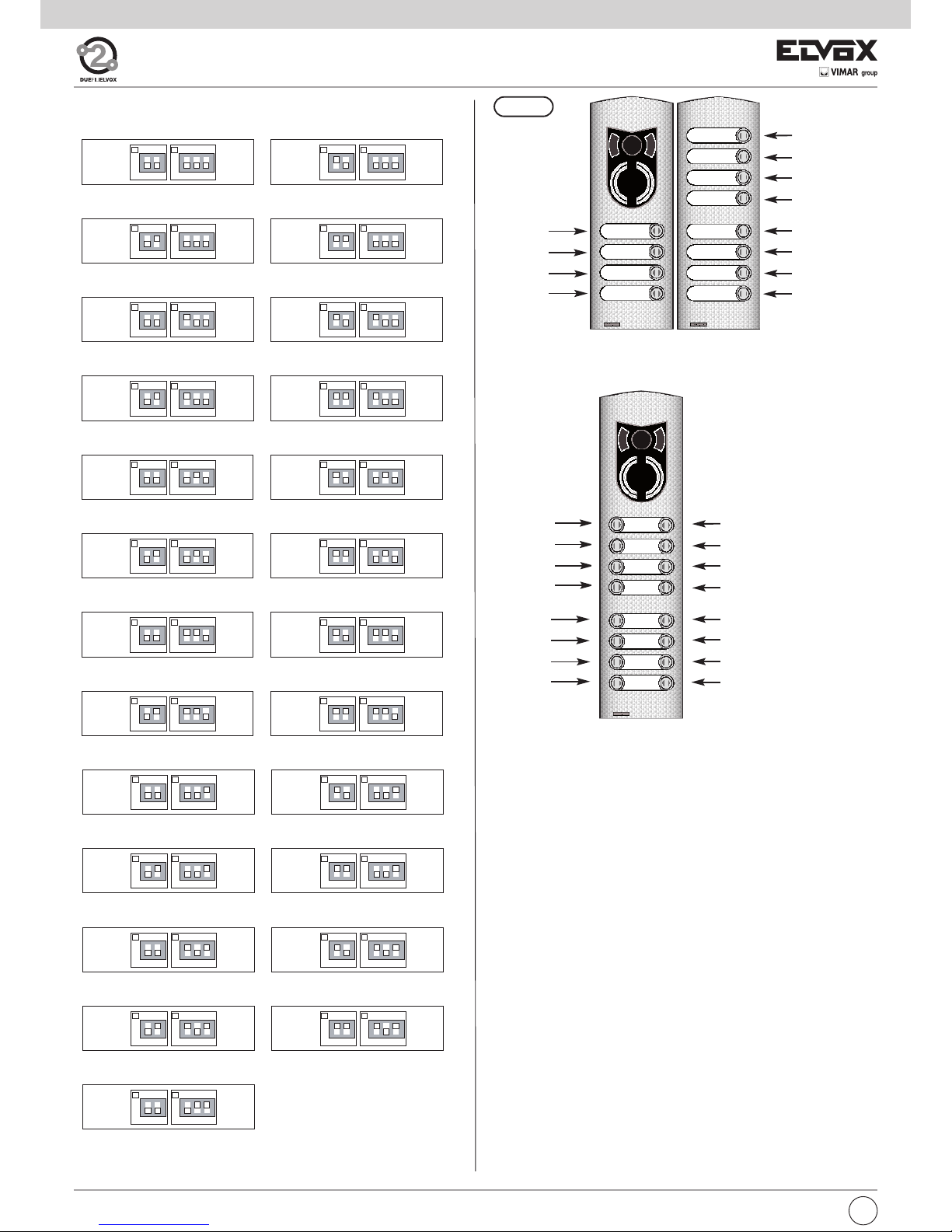
HARDWARE PROGRAMMING OF ADDITIONAL MODULE PUSH-BUTTONS
The dip-switches modify the hardware code of the first pushbutton at the
top right of the module, while the other push-buttons are associated consecutively from top t bottom, right to left (see Tables 1 and 2). Take care not
to overlap the codes of push-buttons on the same panel. When using the
modules with push-buttons in single or double rows the parameter “Single/Double push-buttons” must be programmed according to the type of
module (see standard or advanced programming pages 15 and pages 16).
Fig. 14
PUSHBUTTON HARDWARE PROGRAMMING
(Perform modifications with system switched off)
The hardware programming of push-buttons enables the assignment of a
unique hardware identification code to each pushbutton of the panel. This
operation is indispensable to distinguish each button of the panel and
should only be performed for additional module 805x and 804x. The keys
on the standard modules are already assigned with the numbers from 1 to
8 and the relative hardware programming is not modifiable.
To associate the hardware code use the dip-switches in each additional
module below the white protection of the push-buttons. On 805x series
modules, with push-buttons in single rows, there are 6 dip-switches, while
the 804x series modules, with push-buttons in double rows, there are 5
dip-switches.
ON
123
ON
123
5
6
7
ON
123
ON
123
8
ID ENTRANCE PANEL, IDENTIFICATION PANEL CODE
The identification panel code is required when there is more than one
entrance panel on the installation and only for the panels previously
identified as SLAVE. The operation must be carried out after connecting
all the entrance panels, carrying out the previous operations and powering the installation.
Attention: if the installation power supplies are connected to the elctrical network with more switchers, when switching the installation on, first
power the SLAVE entrance panels and then the MASTER entrance
panel.
Programming may be carried out by means of the programmer type
950C or the PC Software PC SaveProg or by push-buttons from the
entrance panels; if the entrance panel push-buttons are used it is necessary have in the panel a number of push-buttons (different for the physical code) equal to the number of SLAVE entrance panels.
For example:
1) in an installation with 9 entrance panels (1 Master and 8 Slaves) 8 different push-buttons for the 8 entrance panels, provided with the electronic unit.
2) in an installation with 11 entrance panels (1 Master and 10 Slaves) at
least 2 entrance panels out of 11 must be equipped with additional modules to have, besides the 8 standard push-buttons, other 2 pushbttons with different physical codes.
Panel ID programming procedure
Perform the following procedure for each of the SLAVE panels.
- Power up the system. Power first the SLAVE panels followed by the
MASTER panel.
- Wait until the red LEDs indicating ENGAGED/WAIT stop flashing.
- Press and hold the RESET pushbutton (see page 2), of the electronic
unit.
- Press and hold 1st pushbutton at the top right of the electronic unit together with the RESET pushbutton.
- Release the RESET pushbutton while keeping pushbutton (top-right)
for 2 seconds.
- Wait for the panel to emit a high tone from the loudspeaker.
- Enter the Password by pressing the call push-buttons 6 - 5 - 4 - 3 - 2
- 1 in sequence. Each time a pushbutton is pressed, a short “Beep” is
sounded and the output time is renewed (25 seconds), until the next
pushbutton is pressed. The password can only be changed by means
of the programmer type 950C or the PC Software PC SaveProg.
- If the password is correct, the panel emits a high tone of confirmation,
otherwise it emits a low tone and exits the programming phase. The
unit also exits the programming phase when the output time interval
elapses.
- Within 25 seconds, press one of push-buttons to assign the identification code to the SLAVE panel. Pushbutton (top-right) corresponds to
panel 1 SLAVE (ID=2), pushbutton n°2 under n°1 to panel 2 SLAVE
(ID=3) and so on.
If the identification code has already been assigned, the panel emits a long
high tone until another pushbutton is pressed. If the code is available, the
panel emits a low tone and exits the programming phase.
Fig. 13C
Caution!
In order to operate on the programming (PRG) and
Reset push-buttons it is necessary to use the proper
tool usually supplied with the electronic unit.
GB
10
Page 11
ON
123
16
8
4
ON
123
128
64
32
ON
123
16
8
4
ON
123
128
64
32
ON
123
16
8
4
ON
123
128
64
32
ON
123
16
8
4
ON
123
128
64
32
ON
123
16
8
4
ON
123
128
64
32
ON
123
16
8
4
ON
123
128
64
32
ON
123
16
8
4
ON
123
128
64
32
ON
123
16
8
4
ON
123
128
64
32
ON
123
16
8
4
ON
123
128
64
32
ON
123
16
8
4
ON
123
128
64
32
ON
123
16
8
4
ON
123
128
64
32
ON
123
16
8
4
ON
123
128
64
32
ON
123
16
8
4
ON
123
128
64
32
ON
123
16
8
4
ON
123
128
64
32
ON
123
16
8
4
ON
123
128
64
32
ON
123
16
8
4
ON
123
128
64
32
ON
123
16
8
4
ON
123
128
64
32
ON
123
16
8
4
ON
123
128
64
32
129 ... 132 133 ... 136
137 ... 140
145 ... 148
153 ... 156
161 ... 164
169 ... 172
177 ... 180
185 ... 188
193 ... 196
141 ... 144
149 ... 152
157 ... 160
165 ... 168
173 ... 176
181 ... 184
189 ... 192
197 ... 200
ON
123
16
8
4
ON
123
128
64
32
ON
123
16
8
4
ON
123
128
64
32
ON
123
16
8
4
ON
123
128
64
32
ON
123
16
8
4
ON
123
128
64
32
ON
123
16
8
4
ON
123
128
64
32
ON
123
16
8
4
ON
123
128
64
32
105 ... 108 109 ... 112
113 ... 116 117 ... 120
121 ... 124 125 ... 128
ON
123
16
8
4
ON
123
128
64
32
ON
123
16
8
4
ON
123
128
64
32
ON
123
16
8
4
ON
123
128
64
32
ON
123
16
8
4
ON
123
128
64
32
ON
123
16
8
4
ON
123
128
64
32
ON
123
16
8
4
ON
123
128
64
32
ON
123
16
8
4
ON
123
128
64
32
ON
123
16
8
4
ON
123
128
64
32
ON
123
16
8
4
ON
123
128
64
32
ON
123
16
8
4
ON
123
128
64
32
ON
123
16
8
4
ON
123
128
64
32
ON
123
16
8
4
ON
123
128
64
32
ON
123
16
8
4
ON
123
128
64
32
ON
123
16
8
4
ON
123
128
64
32
ON
123
16
8
4
ON
123
128
64
32
ON
123
16
8
4
ON
123
128
64
32
ON
123
16
8
4
ON
123
128
64
32
ON
123
16
8
4
ON
123
128
64
32
ON
123
16
8
4
ON
123
128
64
32
ON
123
16
8
4
ON
123
128
64
32
ON
123
16
8
4
ON
123
128
64
32
ON
123
16
8
4
ON
123
128
64
32
ON
123
16
8
4
ON
123
128
64
32
ON
123
16
8
4
ON
123
128
64
32
ON
123
16
8
4
ON
123
128
64
32
ON
123
16
8
4
ON
123
128
64
32
1 ... 4 5 ... 8
9 ... 12
17 ... 20
25 ... 28
33 ... 36
41 ... 44
49 ... 52
57 ... 60
65 ... 68
73 ... 76
81 ... 84
13 ... 16
21 ... 24
29 ... 32
37 ... 40
45 ... 48
53 ... 56
61 ... 64
69 ... 72
77 ... 80
85 ... 88
89 ... 92 93 ... 96
97 ... 100 101 ... 104
Do not use
11
GB
Page 12
ON
12
16
8
ON
12
16
8
ON
12
16
8
ON
12
16
8
ON
123
128
64
32
ON
123
128
64
32
ON
123
128
64
32
ON
123
128
64
32
ON
12
16
8
ON
12
16
8
ON
12
16
8
ON
12
16
8
ON
123
128
64
32
ON
123
128
64
32
ON
123
128
64
32
ON
123
128
64
32
ON
12
16
8
ON
12
16
8
ON
12
16
8
ON
12
16
8
ON
123
128
64
32
ON
123
128
64
32
ON
123
128
64
32
ON
123
128
64
32
ON
12
16
8
ON
12
16
8
ON
12
16
8
ON
12
16
8
ON
123
128
64
32
ON
123
128
64
32
ON
123
128
64
32
ON
123
128
64
32
ON
12
16
8
ON
12
16
8
ON
12
16
8
ON
123
128
64
32
ON
123
128
64
32
ON
123
128
64
32
ON
12
16
8
ON
12
16
8
ON
12
16
8
ON
123
128
64
32
ON
123
128
64
32
ON
123
128
64
32
ON
12
16
8
ON
123
128
64
32
ON
12
16
8
ON
123
128
64
32
ON
12
16
8
ON
123
128
64
32
0 ... 8 9 ... 16
17 ... 24
33 ... 40
49 ... 56
65 ... 72
81 ... 88
97 ... 104
113 ... 120
129 ... 136
145 ... 152
161 ... 168
177 ... 184
25 ... 32
41 ... 48
57 ... 64
73 ... 80
89 ... 96
105 ... 112
121 ... 128
137 ... 144
153 ... 160
169 ... 176
185 ... 192
193 ... 200
Fig. 15
Art. 1224 Art. 1258
1
2
3
4
5
11
10
9
8
7
6
12
Art. 1246/D
1
11
10
9
4
3
2
12
5
15
14
13
8
7
6
16
TABLE 2 - PUSH-BUTTONS IN DOUBLE ROW
Do not use
GB
12
Page 13

LED switched off
LED switchwed on
DL3 DL4
DL5 DL6
SEQUENCE
NEXT
PREVIOUS
NEXT
DL3 DL4
DL5 DL6
PREVIOUS
NEXT
DL3 DL4
DL5 DL6
PREVIOUS
NEXT
DL3 DL4
DL5 DL6
PREVIOUS
NEXT
DL3 DL4
DL5 DL6
PREVIOUS
NEXT
DL3 DL4
DL5 DL6
PREVIOUS
NEXT
OK
END
DL3 DL4
DL5 DL6
PREVIOUS
NEXT
SINGLE/DOUBLE
PUSH-BUTTONS
OK
END
ANSWER
TIME
OK
END
CONVERSATION
TIME
OK
END
SELF-START
TIME
OK
END
LOCK
TIME
OK
END
F1
TIME
OK
RESET
EEPROM
PROGRAMMING
EXIT
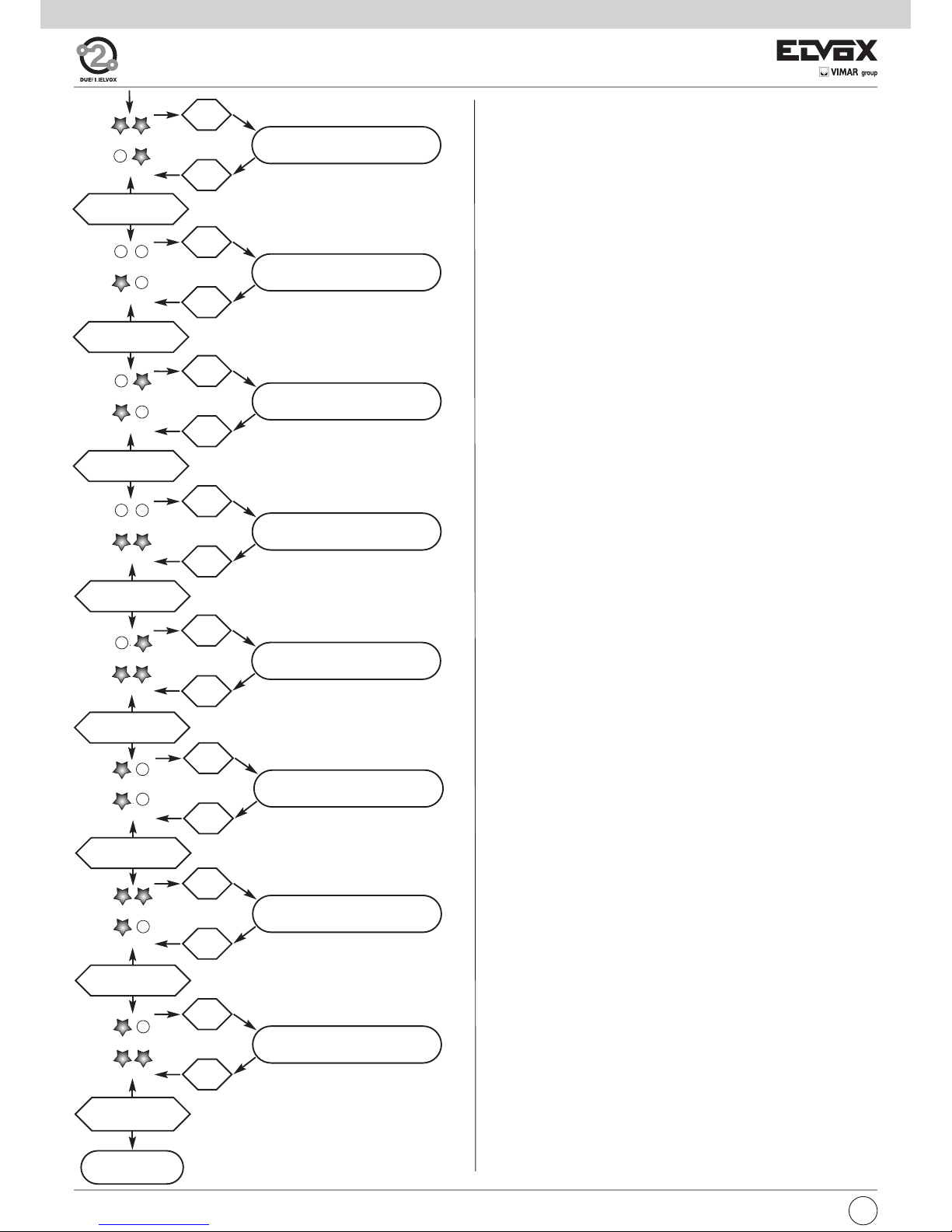
STANDARD PARAMETER PROGRAMMING
Perform the following procedure with the panels powered and after associating the panel ID code. This procedure applies to all panels, Master or
Slave. During programming, the panel is in the engaged status and cannot
be used for normal operation in the system.
For the programming use push-button RPG, 6 push-buttons and 4 green
LEDs present on the electronic unit. In the electronic unit we have in the
whole 8 push-buttons and 6 green LEDs; for the programming the 6 pushbuttons on the lower side and 4 green LEDs on the lower side are used; the
latter serve as indicators for the basic parameter variation. To ease the procedure we call the 4 green LEDs: DL3, DL4, DL5 and DL6.
During programming the 6 push-buttons assume the following functions.
1
PREVIOUS
2
NEXT
3
OK
4
START/YES
5
STOP/NO
6
END
Fig. 15A
Standard programming procedure
- If necessary, press the RESET pushbutton (see par. 2) and wait until the 2
red LEDs stop flashing
- Press the “PRG” push-button and then the push-button on top at the right
hand side and keep them pressed.
- After 2 seconds, the electronic unit emits a high tone for 1 second.
- Enter the Password by pressing the push-buttons 6-5-4-3-2-1 in sequence.
If the password is correct, the 4 LEDs switch off; otherwise it emits a low
tone and exits the programming phase.
- With reference to the following diagram (fig 15B), use the 6 electronic unit
push-buttons to scroll through and modify the parameter values. The
lower 4 LEDs indicate the current function, the push-buttons PREVIOUS
and NEXT select the parameter, the pushbutton OK enters the parameter
editing phase, the pushbutton END exits the parameter editing phase.
The unit also exits the editing phase when the output time interval (30 seconds) elapses, followed by the emission of a low tone for 1 s. The output
time is extended for a further 30 s. when a valid pushbutton is pressed.
For exit from the programming phases, press the RESET pushbutton at any
time.
Fig. 15C
Caution!
In order to operate on the programming (PRG) and Reset push-buttons it
is necessary to use the proper tool usually supplied with the electronic unit.
Fig. 22A
13
GB
Page 14
- RESET EEPROM
Restores all default parameter settings.
On entry to the parameter editing mode, the two red LEDs (DL1 and DL2)
will start to flash 8 times and the panel emits a continuous high tone.
During flashing, press the push-buttons PREVIOUS, OK, STOP in sequence to start deletion of the EEPROM. During deletion, the red LEDs
will start flashing at intervals of 100ms ON / 100ms OFF. On completion
of the deletion process, the panel exits programming mode and the microprocessor is initialised.
- SINGLE/DOUBLE PUSH-BUTTONS
This specifies if the panel push-buttons are in single or double rows.
Default value = push-buttons in single row.
On entry to parameter editing mode, press the pushbutton START/YES
(top left) for single row push-buttons of the pushbutton STOP/NO (middle left) for push-buttons in double rows.
Press the pushbutton END (bottom left) to proceed with the other parameters.
- ANSWER TIME
To be programmed as required. This is the time interval, expressed in
seconds, that the panel waits after a call has been terminated and the
time when the handset of the interphone/monitor is raised. If the handset
is not raised within this time interval, the panel disables the interphone/monitor. If the handset is raised before this interval elapses, the
panel starts to count the conversation time.
Default value = 30 s., minimum value 1 s., maximum value 255 s.
On entry to parameter editing mode, start the count of the time to be
memorised by means of the pushbutton START/YES. To end the count,
press the pushbutton STOP/NO. During the count, the LEDs flash at intervals of 500ms ON/500ms OFF to enable calculation of the time elapsed, 1 flash = 1 s. (e.g. 10 flashes = 10 s.).
Press the pushbutton END to proceed with the other parameters.
- CONVERSATION TIME
To be programmed at user's discretion. This is the time interval, expressed in seconds, that the panel checks, from the time when the handset
is raised after the call. The panel disables the internal unit after this time
interval.Default value = 12 (120 s.), minimum value 10 s., maximum value
2550 s.
On entry to parameter editing mode, start the count of the time to be
memorised by means of the pushbutton START/YES. To end the count,
press the pushbutton STOP/NO. During the count, the LEDs flash at intervals of 500ms ON/500ms OFF to enable calculation of the time elapsed, 1 flash = 1 s. (e.g. 10 flashes = 100 s.).
Press the pushbutton END to proceed with the other parameters.
- SELF-START TIME
To be programmed at the user's discretion. This is the time interval, expressed in seconds, that the panel remains engaged with a monitor/interphone, from activation by means of the self-start function. The
panel disables the internal unit after this time interval.
Default value = 10 s., minimum value 1 s., maximum value 255 s.
On entry to parameter editing mode, start the count of the time to be
memorised by means of the pushbutton START/YES. To end the count,
press the pushbutton STOP/NO. During the count, the LEDs flash at intervals of 500ms ON/500ms OFF to enable calculation of the time elapsed, 1 flash = 1 s. (e.g. 10 flashes = 10 s.).
Press the pushbutton END to proceed with the other parameters.
- LOCK TIME
To be programmed at user's discretion. This is the activation time of
the lock connected between terminals S+ / S- and +12V / SR.
Default value = 1 second, minimum value 0 s., maximum value 5 s.
On entry to parameter editing mode, start the count of the time to be
memorised by means of the pushbutton START/YES. To end the count,
press the pushbutton STOP/NO. During the count, the LEDs flash at
intervals of 500ms ON/500ms OFF to enable calculation of the time
elapsed, 1 flash = 1 s. (e.g. 10 flashes = 10 s.).
Press the pushbutton END to proceed with the other parameters.
To reset the time (0 s.) press the pushbutton STOP/NO in place of the
pushbutton START/YES.
GB
14
DL3 DL4
DL5 DL6
PREVIOUS
NEXT
DL3 DL4
DL5 DL6
PREVIOUS
NEXT
DL3 DL4
DL5 DL6
PREVIOUS
NEXT
DL3 DL4
DL5 DL6
OK
END
F2
TIME
OK
END
REPEAT
PANEL RINGTONE
OK
END
LOCK
BLOCK
OK
END
RINGTONE CYCLES
PREVIOUS
NEXT
DL3 DL4
DL5 DL6
PREVIOUS
NEXT
OK
RESERVED
DL3 DL4
DL5 DL6
OK
END
RESERVED
DL3
DL4
DL6
END
PREVIOUS
NEXT
DL3 DL4
DL5 DL6
PREVIOUS
NEXT
OK
END
PUSHBUTTON
REMAPPING
DL3 DL4
DL5 DL6
OK
END
RESERVED
END
SEQUENCE
PREVIOUS
Page 15

- PUSHBUTTON REMAPPING
Enables modification to the code sent by a pushbutton, regardless of
its physical position assigned with the hardware programming. This
enables use of a pushbutton to call an interphone /monitor that has already been assigned a different code.
Default value = all push-buttons associated with a specific physical
code
On entry to parameter editing mode, the LEDs start flashing; to start
remapping, press the pushbutton START/YES (top left).
After pressing the pushbutton START/YES, press the call pushbutton of
the panel to be remapped. A general call is made from the panel to all
interphones/monitors in the rest condition (not in conversation); the interphones/monitors with handset raised will emit a 3-tone ascending
scale from the loudspeaker.
From this moment the user has a 30-second interval to press, on the interphone/monitor to be associated, the lock push-button.
The panel loudspeaker emits a low tone; this also occurs when the 30second time interval elapses.ù
Press the pushbutton START/YES (top left) to remap other push-buttons or END (bottom left) to proceed with the other parameters.
To restore the default value (Hardware value) of a pushbutton, instead
of pressing START/YES, press STOP/NO and then the pushbutton to
restore the default value and end the procedure.
During this procedure, if the lock pushbutton on the interphone/monitor
concerned is pressed, the panel lock is activated. To eliminate this
event, enable the parameter PANEL BLOCK.
ADVANCED PARAMETER PROGRAMMING
Refer to the instructions for programmer type 950C.
- F1 TIME
To be programmed at user's discretion. This is the activation time of
the device connected between terminals +12V / F1. Default value = 1
second, minimum value 0,5 s., maximum value 255 s.
On entry to parameter editing mode, start the count of the time to be
memorise by means of the pushbutton START/YES. To end the count,
press the pushbutton STOP/NO. During the count, the LEDs flash at
intervals of 500ms ON/500ms OFF to enable calculation of the time
elapsed, 1 flash = 1 s. (e.g. 10 flashes = 10 s.).
Press the pushbutton END to proceed with the other parameters.
To reset the time to 0 (0.5 s.) press the pushbutton STOP/NO in place
of the pushbutton START/YES.
- F2 TIME
To be programmed at user's discretion. This is the activation time of
the device connected between terminals +12V / F2. Default value = 1
second, minimum value 0,5 s., maximum value 255 s.
On entry to parameter editing mode, start the count of the time to be
memorised by means of the pushbutton START/YES. To end the count,
press the pushbutton STOP/NO. During the count, the LEDs flash at
intervals of 500ms ON/500ms OFF to enable calculation of the time
elapsed, 1 flash = 1 s. (e.g. 10 flashes = 10 s.).
Press the pushbutton END to proceed with the other parameters.
To reset the time to 0 (0.5 s.) press the pushbutton STOP/NO in place
of the pushbutton START/YES.
- PANEL RINGTONE ENABLE
To be programmed as required. Enables repetition of the call ringtone
in the loudspeaker of the panel, from the panel where the call is being
made. Default value = enabled
On entry to parameter editing mode, press the pushbutton START/YES
to enable the function, or the pushbutton STOP/NO to disable the function.
Press the pushbutton END (bottom left) to proceed with the other parameters.
- PANEL LOCK BLOCK
To be programmed as required. Activation of the lock block enables
control of the lock only when the panel is in call, conversation or selfstart status. Default value = block disabled
On entry to parameter editing mode, press the pushbutton START/YES
to enable the function, or the pushbutton STOP/NO to disable the function.
Press the pushbutton END (bottom left) to proceed with the other parameters.
- RINGTONE CYCLES
To be programmed at user's discretion. This is the number of times that
the call is repeated in the monitor/interphone when a call pushbutton is
pressed.
Default value = 2 times, minimum value 1, maximum value 20.
On entry to parameter editing mode, start thecount of the cycles to memorised by means of the pushbutton START/YES. To end the count,
press the pushbutton STOP/NO. During the count, the LEDs flash at
intervals of 500ms ON/500ms OFF to enable calculation of the number
of cycles, 1 flash = 1 cycle (e.g. 5 flashes = 5 cycles).
Press the pushbutton END to proceed with the other parameters.
15
GB
Page 16

Table for entrance panels and electronic units for DUE FILI ELVOX (Two Wire Elvox) system
Type of panel
Electronic unit for
1200, 1300 Series
entrance panel
Electronic entrance
panel series 8000
Electronic entrance
panel series PATAVIUM
Electronic entrance
panel series 3300
Electronic entrance
panel series letter box
Alphanumeric audio entrance panel
12F4 89F4 89F4/T 39F4
25F3/8 - 2930
Push-button audio entrance panel
12F3 - 12F3/3
89F3, 89F3/2,
89F3/1, 89F3/0
89F3/T, 89F3/2T,
89F3/1T, 89F3/0T
39F3
25F3/8 - 2930
Alphanumeric video entrance panel
12F7 89F7/C 89F7/CT 39F7
25F3/8 - 2559
Push-button video entrance panel
12F5 -12F5/3
89F5/C, 89F5/C2,
89F5/C1, 89F5/C0
89F5/CT, 89F5/CT2,
89F5/CT1, 89F5/CT0
39F5
25F3/8 - 2559
Conductor section
Terminals Ø up to 10 m Ø up to 50 m Ø up to 100 m Ø up to 300 m
Bus: 1, 2, B1, B2 ( )
0,5 mm
2
0,5 mm
2
0,75 mm
2
1 mm
2
Cable Elvox Type 732H, Type 732I Type 732H, Type 732I Type 732H, Type 732I Type 732H, Type 732I
Electric lock
1,5 mm
2
---
Other: -, +U, +I, -L (#)
1 mm
2
1 mm
2
1,5 mm
2
2,5 mm
2
Video Coaxial cable 75 Ohm type RG59 o RG11 (only for the connection of any external cameras type CCTV)
On Two-Wire installations use cable type 732H or 732I for a maximum distance of 300 metres.
# Additional power supplies (type 6923, 6582, 6982) must be installed as close as possible to the device to which they are to be connected.
BUS TERMINATION FOR ELVOX TWO-WIRE INSTALLATIONS
This note applies to all devices with ELVOX TWO-WIRE technology equipped with “BUS termination connector or dip-switch”, which is identified by the
screen-printed letters “ABC” and marked on the wiring diagrams with
*
.
For correct adaptation of the line, make the setting according to the following rule:
Maintain position “A” if the BUS enters and exits from the device;
Move to position “B” (if Elvox cable) or to position “C” (if CAT5 twisted pair cable) if the BUS line terminates in the device itself.
“A” = NO TERMINATION
“B” = TERMINATION 100 ohm
“C” = TERMINATION 50 ohm
INSTALLATIONS WITH PASSIVE DISTRIBUTOR 692D
(DIN rail version)
ALWAYS use output 1 on distributor type 692D (the only one that has no termination jumper).
For termination of type 692D: If outputs “OUT”, “2”, “3” or “4” are not used, KEEP the jumper on the “TOUT”, “T2”, “T3” or “T4” connector. The default
“TOUT” connector is in the “100” position (Elvox cable), position it to “50” only if using a CAT5 twisted pair cable.
INSTALLATIONS WITH PASSIVE DISTRIBUTOR 692D
(non-DIN rail version)
For termination of type 692D (non-DIN rail version): If the “OUT” output is not used, KEEP the jumper on connector “A”. If the “OUT” output is used, REMOVE the jumper from connector “A”.
INSTALLATIONS WITH ACTIVE DISTRIBUTOR 692D/2.
The termination jumper must be positioned on “B” (for Elvox cable) or on “C” (for CAT5 twisted pair cable) IF AND ONLY IF the BUS terminates at the device itself. It must be left on “A” if effecting entry-exit using terminals 1-2 on 692D/2.
*
GB
16
Page 17

17
B112B2
PRI
EXT+
EXT-
M
PA
X
VLED
B1
B2
S+
S-
F2
F1
SR
-L
+12V
M
M
CA
EXT+
EXT-
M
PA
X
VLED
B1
B2
S+
S-
F2
F1
SR
-L
+12V
M
M
CA
5
2
2
1
4
1
6S
6P
B
A
C
A
C
B
4
5
6S
2
1
6P
1
E+
FP
E-
2
M
CH
+12
B
A
C
4
T2
5
6S
T1
2
1
A
T4
-
+
C
B
VIDEO
T3
6P
1
2
2
2
1
1
12V
CH
B
A
C
FP
M
*
88888888
8
7
R
0
4
1
2
5
9
C
3
6
X
F- Art. 6922
C0
C
P
K
K
K
C
C0
P
L L
X
X
X
X
A1
A3
A2
Mains
K
X
A0
A4
K
X
SINGLE AND MULTIPLE RESIDENCE AUDIO DOOR ENTRY SYSTEM WITH INTERPHONES SERIES PETRARCA, 8870, 6600
AND ONE AUDIO ENTRANCE PANEL (REF. SI435).
Interphone
cable riser
A0 - Interphone type 6901, type 6901/D
A1 - Interphone series Petrarca type 6209
A2 - Interphone series 6600
type 6601/AU, 660C/AU, 6701/AU
type 6611/AU, 661C/AU, 6711/AU, type 6xxx/AUF
A3 - Interphone series 8870 type 8879
C - Audio entry panel with push-buttons
C0 - Audio entry panel with alphanumeric display
F - Power supply type 6922
K - Push-button for outdoor call
L - 12 V ~ electric lock
P - Lock release control
X - Cable type 732H, 732I (Two twisted wires)
Page 18

18
VLED
-L
M
F2
F1
SR
CA
S-
+12V
S+
M
M
PA
X
B2
EXT+
EXT-
B1B1
EXT-
EXT+
B2
X
PA
M
M
S+
+12V
S-
CA
SR
F1
F2
M
-L
VLEDVLED
-L
M
F2
F1
SR
CA
S-
+12V
S+
M
M
PA
X
B2
EXT+
EXT-
B1B1
EXT-
EXT+
B2
X
PA
M
M
S+
+12V
S-
CA
SR
F1
F2
M
-L
VLED
5
2
2
1
4
1
6S
6P
B
A
C
A
C
B
4
5
6S
2
1
6P
1
E+
FP
E-
2
M
CH
+12
B
A
C
4
T2
5
6S
T1
2
1
A
T4
-
+
C
B
VIDEO
T3
6P
1
2
B112B2
PRI
2
2
1
1
12V
CH
B
A
C
FP
M
*
88888888
8
7
R
0
4
1
2
5
9
C
3
6
F- Art. 6922
C0
C
P
K
K
K
C
C0
P
L
L
C
P
L
C
P
L
X
X
X
X
X
X
X
A0
A3
A2
Mains
A1
X
K
C
C
K
X
A4
SINGLE AND MULTIPLE RESIDENCE AUDIO DOOR ENTRY SYSTEM WITH INTERPHONES SERIES PETRARCA, 8870,
6600 AND THREE AUDIO ENTRANCE PANELS (REF. SI338).
Interphone cable riser
A0 - Interphone type 6901, type 6901/D
A1 - Interphone series Petrarca type 6209
A2 - Interphone series 6600
type 6601/AU, 660C/AU, 6701/AU
type 6611/AU, 661C/AU, 6711/AU, type 6xxx/AUF
A3 - Interphone series 8870 type 8879
A4 - Interphone series tab type 7509, 7509/D
C - Audio entry panel with push-buttons
C0 - Audio entry panel with alphanumeric display
F - Power supply type 6922
K - Push-button for outdoor call
L - 12 V ~ electric lock
P - Lock release control
X - Cable type 732H, 732I (Two twisted wires)
Page 19

19
SCHEMA SI334
VLED
-L
M
F2
F1
SR
CA
S-
+12V
S+
M
M
PA
X
B2
EXT+
EXT-
B1
VLED
-L
M
F2
F1
SR
CA
S-
+12V
S+
M
M
PA
X
B2
EXT+
EXT-
B1
1
2
BUS D
12
BUS P
2112
B
A
C
D
2
1
1
2
D
C
A
B
2112
BUS P
21
BUS D
B1
EXT-
EXT+
B2
X
PA
M
M
S+
+12V
S-
CA
SR
F1
F2
M
-L
VLED
VLED
-L
M
F2
F1
SR
CA
S-
+12V
S+
M
M
PA
X
B2
EXT+
EXT-
B1
B112B2
PRI
B112B2
PRI
B112B2
PRI
6
3
C
9
5
2
1
4
0
R
7
8
88888888
*
F- Art. 6922
C0
C
P
C0
L
P
L
C
F- Art. 6922
I- Art. 692S
P
L
F- Art. 6922
L
P
C
C
I- Art. 692S
1
2
5
2
2
1
4
1
6S
6P
B
A
C
A
C
B
4
5
6S
2
1
6P
1
E+
FP
E-
2
M
CH
+12
B
A
C
4
T2
5
6S
T1
2
1
A
T4
+
C
B
VIDEO
T3
6P
1
2
2
2
1
1
12V
CH
B
A
C
FP
M
SI334
SI334
C
C
ID=2
ID=3
ID=1
ID=1
ID=2
X
X
X
X
X
X
X
A1
A2
A3
Mains
Mains
Mains
A0
X
X
X
X
X
K
K
K
K
X
A4
K
Cable riser
A0 - Interphone type 6901, type 6901/D
A1 - Interphone series Petrarca type 6209
A2 - Interphone series 6600
type 6601/AU, 660C/AU, 6701/AU
type 6611/AU, 661C/AU, 6711/AU,
type 6xxx/AUF
A3 - Interphone series 8870 type 8879
A4 - Interphone series tab type 7509, 7509/D
C - Audio entry panel with push-buttons
C0 - Audio entry panel with alphanumeric display
F - Power supply type 6922
I - Separator type 692S
K - Push-button for outdoor call
L - 12 V ~ electric lock
P - Lock release control
X - Cable type 732H, 732I (Two twisted wires)
AUDIO DOOR ENTRY SYSTEM FOR BUILDING COMPLEX WITH ONE MAIN ENTRANCE PANEL AND ONE STAIRWAY
PANEL PER APARTMENT BLOCK (REF. si340+si334).
Page 20

20
VLED
-L
M
F2
F1
SR
CA
S-
+12V
S+
M
M
PA
X
B2
EXT+
EXT-
B1B1
EXT-
EXT+
B2
X
PA
M
M
S+
+12V
S-
CA
SR
F1
F2
M
-L
VLEDVLED
-L
M
F2
F1
SR
CA
S-
+12V
S+
M
M
PA
X
B2
EXT+
EXT-
B1
1
2
D
C
A
B
2112
BUS P
B112B2
PRI
21
BUS D
B1
EXT-
EXT+
B2
X
PA
M
M
S+
+12V
S-
CA
SR
F1
F2
M
-L
VLED VLED
-L
M
F2
F1
SR
CA
S-
+12V
S+
M
M
PA
X
B2
EXT+
EXT-
B1 B1
EXT-
EXT+
B2
X
PA
M
M
S+
+12V
S-
CA
SR
F1
F2
M
-L
VLEDVLED
-L
M
F2
F1
SR
CA
S-
+12V
S+
M
M
PA
X
B2
EXT+
EXT-
B1
BUS D
12
PRI
B221B1
BUS P
2112
B
A
C
D
2
1
B112B2
PRI
B1
EXT-
EXT+
B2
X
PA
M
M
S+
+12V
S-
CA
SR
F1
F2
M
-L
VLED
ID = 1 ID = 2
ID = 1 ID = 2 ID = 3
ID = 4 ID = 5 ID = 6 ID = 7
*
88888888
8
7
R
0
4
1
2
5
9
C
3
6
F- Art. 6922
C
P
L
C
I- Art. 692S
SI334
C
P
L
F- Art. 6922
C
P
L
I- Art. 692S
SI334
C
P
L
C
P
L
C
C
P
L
C
P
L
C0
P
L
C0
ID=1
ID=2 ID=3
ID=4
ID=5
ID=6 ID=7
ID=1
ID=2
X
X
X
X
X
X
X
X
X
F- Art. 6922
Mains
Mains
Mains
C
C
C
C
C
AUDIO DOOR ENTRY SYSTEM FOR BUILDING COMPLEX WITH THREE MAIN ENTRANCE PANELS AND TWO STAIRWAY PANELS PER APARTMENT BLOCK (REF. si341+si334).
C - Audio entry panel with push-buttons
C0 - Audio entry panel with alphanumeric display
F - Power supply type 6922
I - Separator type 692S
K - Push-button for outdoor call
L - 12 V ~ electric lock
P - Lock release control
X - Cable type 732H, 732I (Two twisted wires)
Page 21

21
C
A
B
1
E+
FP
E-
2
M
CH
+12
21
12
1
2
5
4
6P
+
-
6S
T1
T2
C
VIDEO
T4
A
B
T3
M
V3
A
C
B
4
12
2
3
1
13
OUT
IN
2A OUT 1A2B 1B
4B3B 4AIN3A
T2
T3 T4
TOUT
100
50
B
A
C
E-
2
2
1
E+
1
12V
CH
FP
M
C
A
B
1
E+
FP
E-
2
M
CH
+12
+I+U-
PRI
1C 2C2B1A 1B2A
2112
C
13
1
3
2
12
4
V3
M
B
C
A
C
A
B
FP
E-
M
1
E+
2
CH
+12
12
IN
21
OUT
2D1D
BA
C
A
B
1
E+
FP
E-
2
M
CH
+12
+I+U-
PRI
B
A
C
E-
2
2
1
E+
1
12V
CH
FP
M
4
T2
5
6S
T1
2
1
A
T4
+
C
B
VIDEO
T3
6P
4
T2
5
6S
T1
2
1
A
T4
+
C
B
VIDEO
T3
6P
1
2
1
E+
FP
E-
2
M
CH
+12
M
V3
A
C
B
4
12
2
3
1
13
B
A
C
C
A
B
+12
CH
M
2
EFP
E+
1
+I+U-
PRI
21
E-
2
2
1
E+
1
12V
CH
B
A
C
FP
M
X
X
X
X
X
X
X
X
X
N- Art. 692D
N2- Art. 692D/2
K
K
K
K
K
K
K
K
K
K
K
B4
B4
B4
B5
B5
B5
B1
B2
B3
B0
B0
B0
B1
B3 B2
B1
B3
B2
G- Art. 6923
G- Art. 6923
G- Art. 6923
*
*
*
*
*
*
*
*
*
*
*
*
*
Mains
Mains
Mains
K
K
*
B6
K
X
B6
K
B6
*
si638
X
Video door entry system cable riser wiring. The
video door entry units (interphones) can be connected to the cable riser in the following ways:
• in-out connection, without the aid of floor distributors;
• connection with passive distributor type 692D;
• connection with active distributor type 692D/2;
• hybrid connection using the above 3 methods.
In a video installation, device termination must be
carried out using the jumpers (ABC) in the device itself. See the notes below for terminating devices at
the cable riser in accordance with the wiring type.
LEGEND:
B0 - Wide Touch series door entry monitor type 7311
B1 - 7200 series door entry monitor type 7211
B2 - 6600 series door entry monitor
type 6621, 662C, 6721
type 6611, 661C, 6711
B3 - 6800 series door entry monitor
type 6801, type 68MV + 68M1
B4 - Petrarca series door entry monitor
type 6029/C + 6209 + 6145
type 6029 + 6209 + 6145
B5 - Giotto series door entry monitor
type 6329, 6329/C
B6- Tab series door entry monitor
type7529, 7529/D
G - Additional power supply unit type 6923
N - Distributor type 692D
K - Door call button
X- Cable type 732H, 732I (Twisted Pair)
Monitor cable riser
Monitor cable riser
Monitor cable riser
*
CONNECTION OF MONITORS WITH AND WITHOUT FLOOR DISTRIBUTOR TYPE 692D AND 692D/2 (REF. si638).
Page 22

22
EXT+
EXT-
M
PA
X
VLED
B1
B2
S+
S-
F2
F1
SR
-L
+12V
M
M
CA
EXT+
EXT-
M
PA
X
VLED
B1
B2
S+
S-
F2
F1
SR
-L
+12V
M
M
CA
B112B2
PRI
4
T2
5
6S
T1
2
1
A
T4
+
C
B
VIDEO
T3
6P
1
2
1
E+
FP
E-
2
M
CH
+12
M
V3
A
C
B
4
12
2
3
1
13
B
A
C
C
A
B
+12
CH
M
2
E-
FP
E+
1
+I+U-
PRI
E-
2
2
1
E+
1
12V
CH
B
A
C
FP
M
3
2
1
6
9
4
5
7
8
R
0
C
X
R
F- Art. 6922
B2
B3
B1
B4
B5
G- Art. 6923
B0
X
X
X
X
X
X
D0
P
L
D0
D
D
L
*
*
*
*
Mains
Mains
STAR
SI / Y
STO
FINE
END
P
K
K
K
K
X
K
B6
*
SINGLE AND MULTIPLE RESIDENCE VIDEO DOOR ENTRY SYSTEM WITH PETRARCA, GIOTTO AND 6600 SERIES VIDEO INTERPHONES AND ONE VIDEO ENTRANCE PANEL (REF. si433).
Monitor cable riser
B0 - Monitor series Wide touch type 7311
B1 - Monitor series 7200 type 7211
B2 - Monitor series 6600
type 6621, 662C, 6721
type 6611, 661C, 6711,
type 6xxx/F
B3 - Monitor series 6800
type 6801, type 68MV + 68M1
B4 - Monitor series Petrarca
type 6029/C + 6209 + 6145
type 6029 + 6209 + 6145
B5 - Monitor series Giotto
type 6329, 6329/C
B6- Tab series door entry monitor
type7529, 7529/D
D - Video entry panel with push-buttons
F - Power supply type 6922
G - Additional power supply type 692S
K - Push-button for outdoor call
L - 12 V ~ electric lock
P - Lock release control
X - Cable type 732H, 732I (Two twisted wires)
Page 23

23
2C 1D 2D1C2B1B2A1A
21122112
+
PRI
B221B1
1C 2C2B1A 1B2A
2112
C
2D1D
BA
1
22
1
2
1
CA
M
M
+12V
-L
SR
F1
F2
S-
S+
B2
B1
VLED
X
PA
M
EXT-
EXT+EXT+
EXT-
M
PA
X
VLED
B1
B2
S+
S-
F2
F1
SR
-L
+12V
M
M
CA CA
M
M
+12V
-L
SR
F1
F2
S-
S+
B2
B1
VLED
X
PA
M
EXT-
EXT+
4
T2
5
6S
T1
2
1
A
T4
-
+
C
B
VIDEO
T3
6P
1
2
1
E+
FP
E-
2
M
CH
+12
M
V3
A
C
B
4
12
2
3
1
13
B
A
C
C
A
B
+12
CH
M
2
EFP
E+
1
+I+U-
PRI
E-
2
2
1
E+
1
12V
CH
B
A
C
FP
M
R
3
2
1
6
9
4
5
7
8
R
0
C
X
R R
D0
P
L
D0
F- Art. 6922
D
P
D
Mains
K
K
N2Art. 692D/2
J- Art. 692C
X
X
X
X
X
X
X
B1
B3
B0
*
*
STA
SI /
STO
FIN
K
L
*
*
K
B2
B6
B4
B5
*
K
*
G- Art. 6923
Mains
P
L
X
X
X
X
X
D
D
STA
SI /
STO
FIN
WIRING DIAGRAM FOR “TWO WIRE ELVOX” VIDEO INTERPHONE INSTALLATIONS WITH TWO OR MORE MONITOR RISERS WITH DISTRIBUTORS TYPE 692D/2 (SI424).
Monitor cable riser
B0 - Monitor series Wide touch type 7311
B1 - Monitor series 7200 type 7211
B2 - Monitor series 6600
type 6621, 662C, 6721
type 6611, 661C, 6711,
type 6xxx/F
B3 - Monitor series 6800
type 6801, type 68MV + 68M1
B4 - Monitor series Petrarca
type 6029/C + 6209 + 6145
type 6029 + 6209 + 6145
B5 - Monitor series Giotto
type 6329, 6329/C
B6- Tab series door entry monitor
type7529, 7529/D
D - Video entry panel with push-buttons
D0 - Video entry panel with alphanumeric display
F - Power supply type 6922
J - Concentrator type 692C
K - Push-button for outdoor call
L - 12 V ~ electric lock
N2 - Active video distributor type 692D/2
P - Lock release control
X - Cable type 732H, 732I (Two twisted wires)
Page 24

24
CA
M
M
+12V
-L
SR
F1
F2
S-
S+
B2
B1
VLED
X
PA
M
EXT-
EXT+
PRI
B221B1
CA
M
M
+12V
-L
SR
F1
F2
S-
S+
B2
B1
VLED
X
PA
M
EXT-
EXT+
MV-+T
-L-+U
PRI
4
T2
5
6S
T1
2
1
A
T4
-
+
C
B
VIDEO
T3
6P
1
2
1
E+
FP
E-
2
M
CH
+12
M
V3
A
C
B
4
12
2
3
1
13
B
A
C
C
A
B
+12
CH
M
2
E-
FP
E+
1
+I+U-
PRI
E-
2
2
1
E+
1
12V
CH
B
A
C
FP
M
88888888
*
8
7
R
0
4
1
2
5
9
C
3
6
K
K
F- Art. 6922
C
P
L
C
C0
P
L
C0
S- Art. 6982
M1
K
Coax 75 ohm
X
X
X
X
X
B4
B5
*
*
*
Mains
Mains
X
G- Art. 6923
Mains
B0
B1
B2
B3
*
K
X
B6
*
K
B0 - Monitor series Wide touch type 7311
B1 - Monitor series 7200 type 7211
B2 - Monitor series 6600
type 6621, 662C, 6721
type 6611, 661C, 6711,
type 6xxx/F
B3 - Monitor series 6800
type 6801, type 68MV + 68M1
B4 - Monitor series Petrarca
type 6029/C + 6209 + 6145
type 6029 + 6209 + 6145
B5 - Monitor series Giotto
type 6329, 6329/C
B6- Tab series door entry monitor
type 7529, 7529/D
C - Audio entry panel with push-buttons
C0 - Audio entry panel with alphanumeric display
F - Power supply type 6922
K - Push-button for outdoor call
L - 12 V ~ electric lock
M1 - 12 V C.C.T.V. external camera
max current 250mA intermittent cycle or
150mA continuous cycle
P - Lock release control
S - Additional power supply type 6982
X - Cable type 732H, 732I (Two twisted wires)
Monitor cable riser
VIDEO ENTRANCE PANEL SYSTEM FOR SINGLE AND TWIN RESIDENCE WITH MONITORS SERIES PETRARCA,
GIOTTO, 6600, ONE ENTRANCE PANEL WITH EXTERNAL CAMERA IN B/W (Ref. SI367).
Page 25

25
EXT+
EXT-
M
PA
X
VLED
B1
B2
S+
S-
F2
F1
SR
-L
+12V
M
M
CA
1
2
BUS D
12
PRI
B221B1
BUS P
2112
B
A
C
D
CA
M
M
+12V
-L
SR
F1
F2
S-
S+
B2
B1
VLED
X
PA
M
EXT-
EXT+
B112B2
PRI
D
C
A
B
2112
BUS P
B112B2
PRI
21
BUS D
21
OUT
21
OUT
VIDEO
B
A
C
T3
T4
T2
T1
6S
+
6P
4
5
2
1
1C 2C2B1A 1B2A
2112
C
13
1
3
2
12
4
V3
M
B
C
A
C
A
B
FP
E-
M
1
E+
2
CH
+12
2D1D
BA
B
A
C
E-
2
2
1
E+
1
12V
CH
FP
M
VIDEO
B
A
C
T3
T4
T2
T1
6S
+
6P
4
5
2
1
1C 2C2B1A 1B2A
2112
C
13
1
3
2
12
4
V3
M
B
C
A
C
A
B
FP
E-
M
1
E+
2
CH
+12
2D1D
BA
B
A
C
E-
2
2
1
E+
1
12V
CH
FP
M
3
2
1
6
9
4
5
7
8
R
0
C
X
R
D0
P
L
D0
D
P
L
D
F- Art. 6922
F- Art. 6922
K
K
K
K
K
K
I- Art. 692S
X
K
X
X
X
X
B4
B5
B5
B3
B4
*
*
*
*
*
*
*
Mains
Mains
STA
SI /
STO
X
B2
B1
*
B6
B3
B2
B1
K
B6
I- Art. 692S
N2Art. 692D/2
N2Art. 692D/2
X
F- Art. 6922
Mains
*
*
SINGLE AND MULTIPLE RESIDENCE VIDEO DOOR ENTRY SYSTEM WITH INTERCOMMUNICATING MONITORS (REF.
si611).
B0 - Monitor series Wide touch type 7311
B1 - Monitor series 7200 type 7211
B2 - Monitor series 6600
type 6621, 662C, 6721
type 6611, 661C, 6711,
type 6xxx/F
B3 - Monitor series 6800
type 6801, type 68MV + 68M1
B4 - Monitor series Petrarca
type 6029/C + 6209 + 6145
type 6029 + 6209 + 6145
B5 - Monitor series Giotto
type 6329, 6329/C
B6- Tab series door entry monitor
type 7529, 7529/D
D - Video entry panel with push-buttons
D0 - Video entry panel with alphanumeric display
F - Power supply type 6922
I - Separator type 692S
K - Push-button for outdoor call
L - 12 V ~ electric lock
P - Lock release control
X - Cable type 732H, 732I (Two twisted wires)
Monitor cable riser
Monitor cable riser
Page 26

26
1
2
M
PA
X
B1
B2
S+
S-
F2
F1
SR
-L
M
M
CA
EXT+
EXTVLED
+12V
BUS D
12
PRI
B221B1
BUS P
2112
B
A
C
D
2
11
2
D
C
A
B
2112
BUS P
B112B2
PRI
21
BUS D
B1
EXT-
EXT+
B2
X
PA
M
M
S+
+12V
S-
CA
SR
F1
F2
M
-L
VLED
CA
M
M
+12V
-L
SR
F1
F2
S-
S+
B2
B1
VLED
X
PA
M
EXT-
EXT+
B112B2
PRI
EXT+
EXT-
M
PA
X
VLED
B1
B2
S+
S-
F2
F1
SR
-L
+12V
M
M
CA
3
2
1
6
9
4
5
7
8
R
0
C
X
R
D0
P
L
D0
D
P
L
D
F- Art. 6922
F- Art. 6922
I- Art. 692S
ID=2
I- Art. 692S
F- Art. 6922
ID=2
C
C
P
L
ID=3
P
L
ID=1
D
D
ID=1
X
X
X
X
X
*
*
Mains
Mains
Mains
STA
SI / Y
STO
FINE
STA
SI / Y
STO
FINE
VIDEO DOOR ENTRY SYSTEM FOR BUILDING COMPLEX (REF. SI380).
Monitor cable riser
Monitor cable riser
C - Audio entry panel with push-buttons
C0 - Audio entry panel with alphanumeric display
D - Video entry panel with push-buttons
D0 - Video entry panel with alphanumeric display
F - Power supply type 6922
I - Separator type 692S
K - Push-button for outdoor call
L - 12 V ~ electric lock
P - Lock release control
X - Cable type 732H, 732I (Two twisted wires)
Cable riser
Page 27

27
2C 1D 2D1C2B1B2A1A
21122112
+
2C 1D 2D1C2B1B2A1A
21122112
+
B1
EXT-
EXT+
B2
X
PA
M
M
S+
+12V
S-
CA
SR
F1
F2
M
-L
VLEDVLED
-L
M
F2
F1
SR
CA
S-
+12V
S+
M
M
PA
X
B2
EXT+
EXT-
B1
VLED
-L
M
F2
F1
SR
CA
S-
+12V
S+
M
M
PA
X
B2
EXT+
EXT-
B1
BUS D
12
PRI
B221B1
BUS P
2112
B
A
C
D
2
1
S+
S-
F2
F1
SR
-L
+12V
M
M
CACA
M
M
+12V
-L
SR
F1
F2
S-
S+
EXT+
EXT-
M
PA
X
VLED
B1
B2B2
B1
VLED
X
PA
M
EXT-
EXT+
B112B2
PRI
EXT+
EXT-
M
PA
X
VLED
B1
B2
S+
S-
F2
F1
SR
-L
+12V
M
M
CACA
M
M
+12V
-L
SR
F1
F2
S-
S+
B2
B1
VLED
X
PA
M
EXT-
EXT+
1
2
D
C
A
B
2112
BUS P
B112B2
PRI
21
BUS D
+
-
2112 2112
1A 2A 1B 2B 1C 2D1D2C
EXT+
EXT-
M
PA
X
VLED
B1
B2
S+
S-
F2
F1
SR
-L
+12V
M
M
CA
2
1
2
1
2
1
2
1
2
1
AB
1D 2D
C
2112
2A 1B1A 2B 2C1C
AB
1D 2D
C
212C12
2A 1B1A 2B 2C1C
3
2
1
6
9
4
5
7
8
R
0
C
X
R
P
L
D0
D0
F- Art. 6922
F- Art. 6922
I- Art. 692S
ID=2
I- Art. 692S
F- Art. 6922
ID=4
P
L
ID=1
D
D
ID=1
J- Art. 692C
P
L
D
ID=2
P
L
D
ID=3
P
L
J- Art. 692C
ID=5
P
L
D
D
J- Art. 692C
ID=6
P
L
C
C
ID=7
P
L
C
C
X
X
X
X
X
X
X
X
X
XX
*
*
Mains
Mains
Mains
STA
SI /
STO
FIN
STA
SI / Y
STO
FINE
STA
SI / Y
STO
FINE
X
X
N2Art. 692D/2
ID=4
N2Art. 692D/2
D
D
STA
SI /
STO
FIN
D
D
STA
SI /
STO
FIN
VIDEO DOOR ENTRY SYSTEM FOR BUILDING COMPLEX WITH THREE MAIN ENTRANCE PANELS AND TWO STAIRWAY PANELS PER APARTMENT BLOCK (AUDIO AND VIDEO) (REF. SI382).
C - Audio entry panel with push-buttons
C0 - Audio entry panel with alphanumeric display
D - Video entry panel with push-buttons
D0 - Video entry panel with alphanumeric display
F - Power supply type 6922
I - Separator type 692S
J - Concentrator type 692C
L - 12 V ~ electric lock
N2 - Active video distributor type 692D/2
P - Lock release control
X - Cable type 732H, 732I (Two twisted wires)
Monitor cable riser
Monitor cable riser
Page 28
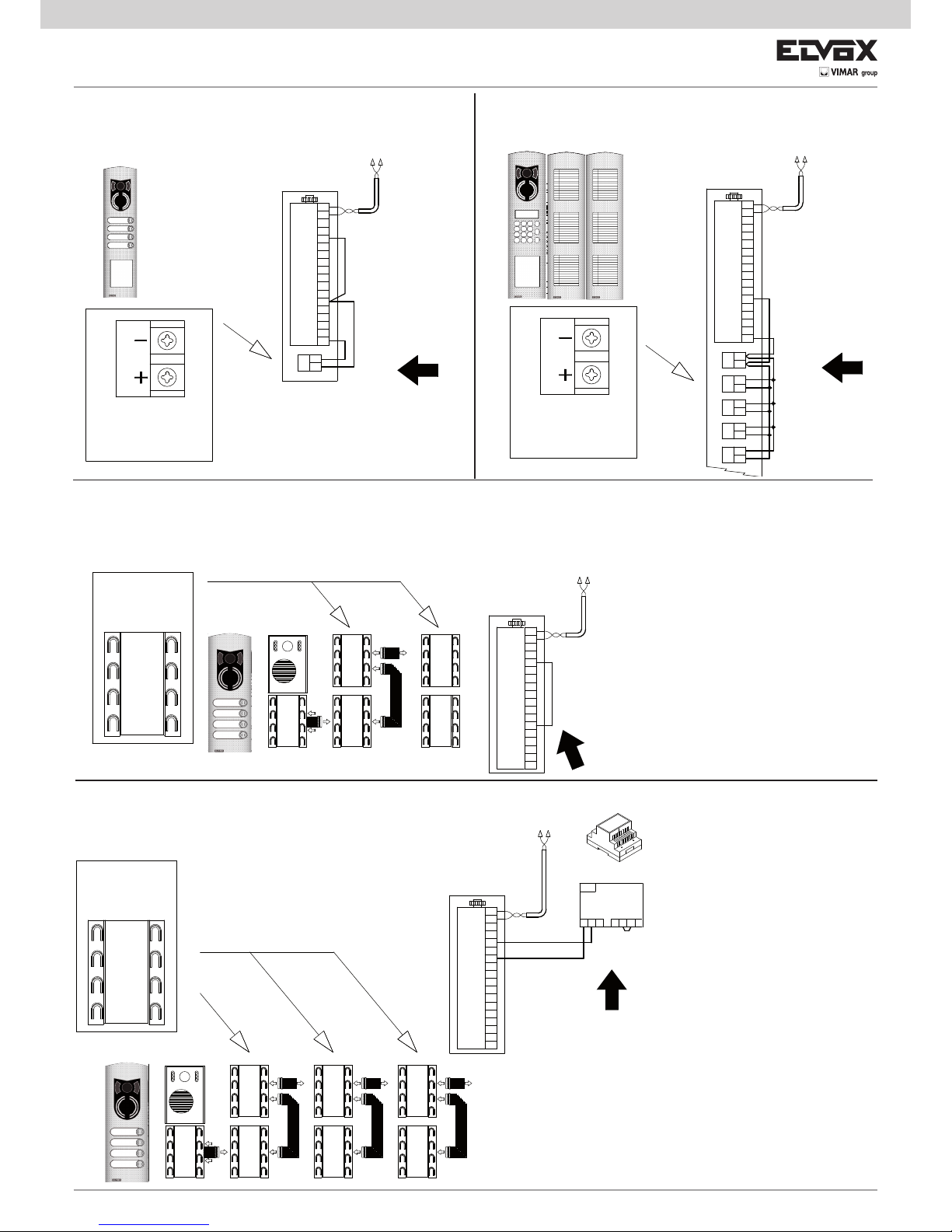
28
ELVOX
1
2
EXT+
EXT-
M
PA
X
VLED
B1
B2
S+
S-
F2
F1
SR
-L
+12V
M
M
CA
+
-
ELVOX ELVOX ELVOX
Sign lighting circuit
for 15 names (for
panel Art. 122N,
123N).
ELVOX
ELVOX ELVOX ELVOX ELVOX
1
2
EXT+
EXT-
M
PA
X
VLED
B1
B2
S+
S-
F2
F1
SR
-L
+12V
M
M
CA
ELVOX ELVOX ELVOX
ELVOX
ELVOX ELVOX ELVOX ELVOX
1
2
EXT+
EXT-
M
PA
X
VLED
B1
B2
S+
S-
F2
F1
SR
-L
+12V
M
M
CA
PRI
DBAC+U-+I
ELVOX ELVOX ELVOX
Art. 6582
ELVOX ELVOX ELVOX
1
2
EXT+
EXT-
M
PA
X
VLED
B1
B2
S+
S-
F2
F1
SR
-L
+12V
M
M
CA
+
-
+
-
+
-
+
-
+
-
VARIANT
Electronic unit with alphanumeric keyboard, backlit sign with house
number (panel Art. 12N4, 12N3, 12N2, 12N1)
VARIANT
Electronic unit with alphanumeric keyboard (up to 8 modules type
805N, 80PN).
Monitor cable riser
Perform wiring
Sign lighting circuit
for 15 names (for
panel Art. 122N,
123N).
Perform wiring
Monitor cable riser
VARIANT
Electronic unit with additional button modules (up to 4 modules type 12TS, 8051, 8052, 8054, 8042, 8044, 8046, 8048)
Additional button module
12TS, 8051, 8052,
8053, 8054, 8042
8044, 8046, 8048
Perform VLED/+12
wiring
Monitor cable riser
VARIANT
Electronic unit with additional button modules (from 5 to 30 modules type 12TS, 8051, 8052, 8054, 8042, 8044, 8046, 8048)
Additional button module
12TS, 8051, 8052,
8053, 8054, 8042
8044, 8046, 8048
Mains
Add power
supply
NOTE: type 12TS for 1200 and 1300 series
NOTE: type 805x for type 89F3/… and 89F5…, are sold complete with
8000 series plate.
Monitor cable riser
Page 29

29
ELVOX ELVOX ELVOX ELVOX
ELVOX ELVOX ELVOX ELVOX
1
2
PRI
DBAC+U-+I
+
-
+
-
+
-
+
-
+
-
PRI
DBAC+U-+I
PRI
DBAC+U-+I
EXT+
EXT-
M
PA
X
VLED
B1
B2
S+
S-
F2
F1
SR
-L
+12V
M
M
CA
Mains
Art. 6582
Mains Mains
Art. 6582
Art. 6582
VARIANT
Connection of additional power supply type 6923..
VARIATION
Connection of auxiliary functions F1 and F2
Functions F1 and F2 can be activated from the interphones and video interphones by connecting a relay
type 0170/001 to terminals F1 and F2 of the entrance
panel.
P
L
Art. 732H
C/D
Q -
Art. 170/001
Q -
Art. 170/001
1
2
EXT+
EXT-
M
PA
X
VLED
B1
B2
S+
S-
F2
F1
SR
-L
+12V
M
M
CA
1 2 3 4 5 5 4 3 2 1
P
L
QArt. 0170/001
L
P
G - Art. 6923
Art. 732H
C/D
C/D
CA
M
M
+12V
-L
SR
F1
F2
S-
S+
B2
B1
VLED
X
PA
M
EXT-
EXT+
2
1
PRI
-+U
+I
123
456
789
0
ABC DEF
GHI JKL MNO
PQRS TUV WXYZ
.,;
R
CANC
G- Art. 6923
P
L
C0/
D0
C0/D0
Mains
X
VARIANTE
Connection of lock with additional power supply
To open high power locks, an external transformer may be used, which powers the lock by
means of a relay type 0170/001, connected to terminals +12V/SR of the entrance panel. The lock
opening time is the same as that set on terminals
S+/S-.
L
P
Art. 732H
C/D
Q -
Art. 170/001
R -
Art. 832/030
5 4 3 2 1
PRI
15 0
CA
M
M
+12V
-L
SR
F1
F2
S-
S+
B2
B1
VLED
X
PA
M
EXT-
EXT+
2
1
P
L
RArt. 0832/030
QArt. 0170/001
A
T
X
C0/D0
A
T
C0/
D0
X
QArt. 0170/001
C0/
D0
Mains
C/C0 - Targa esterna audio a pulsanti o alfanumerica
D/D0 - Targa esterna video a pulsanti o alfanumerica
L - 12 V ~ electric lock
P - Comando apriporta
Q - Relay Art. 0170/001
X - Cavo Art. 732H, 732I (Due Fili Twistati)
C0/D0
ELVOX ELVOX ELVOX ELVOX
1
2
EXT+
EXT-
M
PA
X
VLED
B1
B2
S+
S-
F2
F1
SR
-L
+12V
M
M
CA
PRI
DBAC+U-+I
+
-
+
-
+
-
+
-
+
-
VARIANT
Electronic unit with alphanumeric keyboard (over 60 modules type
805N, 80PN).
VARIANT
Electronic unit with alphanumeric keyboard (with 9 to 60 modules
type 805N, 80PN).
Monitor cable riser
Monitor cable riser
type 6582
Sign lighting circuit
for 15 names (for
panel Art. 122N,
123N).
Sign lighting circuit for 15 names
(for panel Art.
122N, 123N).
F1
function
Load
maximum
230V~ 3A
F2
function
Load
maximum
230V~ 3A
C0 - Audio entry panel with alphanumeric display
D0 - Video entry panel with alphanumeric display
G - Additional power supply type 6923
L - 12 V ~ electric lock
P - Lock release control
Q - Relay Art. 0170/001
R - Transformer Art. 0832/030
X - Cable Art. 732H, 732I (Two twisted wires)
C/C0 -Audio entry panel with alphanumeric display
D/D0 -Video entry panel with alphanumeric display
L - 12 V ~ electric lock
P - Lock release control
X - Cable Art. 732H, 732I (Two twisted wires)
Add power supply for the first
60 modulesi
Add power
supply for the
next 60 modules
Add power
supply for the
next 60 modules
Page 30

30
A
C
B
1
2
4
5
6S
2
1
6P
K
K
1
T2
5
T3
6S
T1
2
4
T4
A
C
B
-
+
VIDEO
6P
1
2
K
K
2
1
M
4
12
2
3
1
V3
13
A
C
B
K
K
2
1
+12
CH
M
2
EFP
E+
1
C
A
B
K
2
1
+12
CH
M
2
EFP
E+
1
C
A
B
K
B1
B2
B3
A1
A2
A3
B5
C
A
B
+12
CH
M
2
E-
FP
E+
1
K
+I+U-
PRI
G- Art. 6923
B0
Mains
K
2
1
2
1
2
2
1
1
12V
CH
B
A
C
FP
M
A4
K
2
1
2
1
E-
2
2
1
E+
1
12V
CH
B
A
C
FP
M
B6
K
5
2
2
1
4
1
6S
6P
B
A
C
K
2
1
A0
K
VARIANT
Wiring diagram for additional mechanical doorbells.
Additional doorbells operating at 12V can be connected by using relay type 0170/101 connected as shown in the diagram.
A0 - Interphone type 6901, type 6901/D
A1 - Interphone series Petrarca type 6209
A2 - Interphone series 6600
type 6601/AU, 660C/AU, 6701/AU
type 6611/AU, 661C/AU, 6711/AU, type 6xxx/AUF
A3 - Interphone series 8870 type 8879
A4 - Interphone series tab type 7509, 7509/D
B0 - Monitor series Wide touch type 7311
B1 - Monitor series 7200 type 7211
B2 - Monitor series 6600
type 6621, 662C, 6721
type 6611, 661C, 6711, type 6xxx/F
B3 - Monitor series 6800
type 6801, type 68MV + 68M1
B4 - Monitor series Petrarca
type 6029/C + 6209 + 6145
type 6029 + 6209 + 6145
B5 - Monitor series Giotto type 6329, 6329/C
B6- Tab series door entry monitor type 7529, 7529/D
K - Push-button for outdoor call
X - Cable type 732H, 732I (Two twisted wires)
Page 31

31
8574PRI
2
1
1
E+
FP
E-
2
M
CH
+12
B
A
C
+I+U-
PRI
B
C
A
8574PRI
2
1
6P
1
2
6S
5
4
8574PRI
4
A
T2
T4
T3
5
6S
+
6P
C
B
VIDEO
T1
2
1
2
1
Mains
Mains
8 5 7 4 PRI
2
1
2
1
13
V3
1
3
2
12
4
M
B
C
A
Mains
8 5 7 4 PRI
2
1
1
E+
FP
E-
2
M
CH
+12
B
A
C
Ringtone
Art. 860A
Mains
8 5 7 4 PRI
2
1
1
E+
FP
E-
2
M
CH
+12
B
A
C
Mains
B1
B2
B3
A1
A3
A2
B5
G- Art. 6923
B0
Ringtone
Art. 860A
Ringtone
Art. 860A
Ringtone
Art. 860A
Ringtone
Art. 860A
Ringtone
Art. 860A
Mains
Mains
2
1
2
1
8574PRI
E-
2
2
1
E+
1
12V
CH
B
A
C
FP
M
B6
K
Ringtone
Art. 860A
Mains
2
1
2
1
8574PRI
2
2
1
1
12V
CH
B
A
C
FP
M
A4
K
Ringtone
Art. 860A
Mains
8574PRI
5
2
2
1
4
1
6S
6P
B
A
C
2
1
A0
Ringtone
Art. 860A
Mains
VARIANT
Wiring diagram of additional electronic ringtone type 860A.
The electronic ringtone type 860A features a two or three-note ringtone connected between terminal 7 and terminal 8. The ringtone must be powered at
mains voltage. The doorbell rhithm follows the call push- button pressure.
A0 - Interphone type 6901, type 6901/D
A1 - Interphone series Petrarca type 6209
A2 - Interphone series 6600
type 6601/AU, 660C/AU, 6701/AU
type 6611/AU, 661C/AU, 6711/AU, type 6xxx/AUF
A3 - Interphone series 8870 type 8879
A4 - Interphone series tab type 7509, 7509/D
B0 - Monitor series Wide touch type 7311
B1 - Monitor series 7200 type 7211
B2 - Monitor series 6600
type 6621, 662C, 6721
type 6611, 661C, 6711, type 6xxx/F
B3 - Monitor series 6800
type 6801, type 68MV + 68M1
B4 - Monitor series Petrarca
type 6029/C + 6209 + 6145
type 6029 + 6209 + 6145
B5 - Monitor series Giotto type 6329, 6329/C
B6- Tab series door entry monitor type 7529, 7529/D
G - Additional power supply type 692G
X - Cable type 732H, 732I (Two twisted wires)
Page 32

32
A
C
B
1
2
4
5
6S
2
1
6P
15 5243
RC
-
+
C1
1C
+
-
RC
342515
1
22
T1
VIDEO
B
C
6P
+
-
6S
5
T3
T4
T2
A
4
1
Relay
Art. 0170/101
Relay
Art. 0170/101
1
2
13
V3
1
3
2
12
4
M
15 5243
RC
-
+
C1
B
C
A
Relay
Art. 0170/101
1
2
+12
CH
M
2
E-
FP
E+
1
15 5243
RC
-
+
C1
C
A
B
Relay
Art. 0170/101
1
2
+12
CH
M
2
EFP
E+
1
15 5243
RC
-
+
C1
C
A
B
Relay
Art. 0170/101
B1
B2
B3
B5
A1
A3
2
1
2
1
15 5243
RC
-
+
C1
E-
2
2
1
E+
1
12V
CH
B
A
C
FP
M
B6
K
Relay
Art. 0170/101
2
1
2
1
15 5243
RC
-
+
C1
2
2
1
1
12V
CH
B
A
C
FP
M
A6
K
Max Last
3A 230V
Relay
Art. 0170/101
15 5243
RC
-
+
C1
5
2
2
1
4
1
6S
6P
B
A
C
2
1
Max Last 3A 230V
A0
VARIANT
Wiring diagram for additional mechanical doorbells.
Additional doorbells operating at 12V can be connected by using relay type 0170/101 connected as shown in the diagram.
A2
Relay
Art. 0170/101
Max Last
3A 230V
A0 - Interphone type 6901, type 6901/D
A1 - Interphone series Petrarca type 6209
A2 - Interphone series 6600
type 6601/AU, 660C/AU, 6701/AU
type 6611/AU, 661C/AU, 6711/AU, type
6xxx/AUF
A3 - Interphone series 8870 type 8879
A4 - Interphone series tab type 7509, 7509/D
B0 - Monitor series Wide touch type 7311
B1 - Monitor series 7200 type 7211
B2 - Monitor series 6600
type 6621, 662C, 6721
type 6611, 661C, 6711, type 6xxx/F
B3 - Monitor series 6800
type 6801, type 68MV + 68M1
B4 - Monitor series Petrarca
type 6029/C + 6209 + 6145
type 6029 + 6209 + 6145
B5 - Monitor series Giotto type 6329, 6329/C
B6- Tab series door entry monitor type 7529,
7529/D
G - Additional power supply type 6923
X - Cable type 732H, 732I (Two twisted wires)
Ringtone power supply
Additional ringtone
Ringtone power supply
Additional ringtone
Ringtone power supply
Additional ringtone
Ringtone power supply
Additional ringtone
Ringtone power supply
Additional ringtone
Ringtone power supply
Additional ringtone
Ringtone power supply
Additional ringtone
Additional ringtone
Ringtone power supply
Page 33

33
6P
T3
VIDEO
B
C
+
-
T4
A
1
2
T1
6S
5
T2
4
4
T2
5
6S
T1
2
1
A
T4
+
C
B
VIDEO
T3
6P
C
VIDEO
6P
T3
+
-
T4
A
1
2
T1
6S
5
T2
4
B
+U-
PRI
21
1
2
+I
G- Art. 6923
Mains
G- Art. 6923
2
1
1
2
PRI
-
+U
M
4
12
2
3
1
V3
13
13
V3
1
3
2
12
4
M
13
V3
1
3
2
12
4
M
+I
A
C
B
B
C
A
B
C
A
Mains
2
1
1
2
PRI
-+U
+12
CH
M
2
E-
FP
E+
1
1
E+
FP
E-
2
M
CH
+12
+12
CH
M
2
E-
FP
E+
1
+I
C
A
B
B
A
C
C
A
B
G- Art. 6923
Mains
X
X
X
X
X
X
X
X
X
B1
B2
B3
B5
B5
B5
B4
B4
B4
1
2
C
A
B
+12
CH
M
2
E-
FP
E+
1
15 5243
RC
-
+
C1
+I+U-
PRI
G- Art. 6923
B0
Relay
Art. 0170/101
Mains
VARIANT
Wiring diagram with simultaneous switch-on of two or more monitors with power supply type 6923.
The power supply unit Type 6922 can simultaneously power one video
entrance panel and two monitors Type 6029, 6029/C, 6611, 6621, 661C,
662C, 6711, 6721 switched on.
With a larger number of monitors switched on simultaneously, additional power supply type 6923 must be used after the 2nd monitor. One
power supply type 6923 must be used per additional monitor.
B0 - Monitor series Wide touch type 7311
B1 - Monitor series 7200 type 7211
B2 - Monitor series 6600
type 6621, 662C, 6721
type 6611, 661C, 6711, type 6xxx/F
B3 - Monitor series 6800
type 6801, type 68MV + 68M1
B4 - Monitor series Petrarca
type 6029/C + 6209 + 6145
type 6029 + 6209 + 6145
B5 - Monitor series Giotto type 6329, 6329/C
K - Push-button for outdoor call
X - Cable type 732H, 732I (Two twisted wires)
Additional ringtone
Ringtone power supply
Page 34

34
ADDITIONAL SUPPLY VOLTAGES
In “Elvox TWO WIRE ” installations, power supply type 6922 powers all the appliances: entrance panels, interphones, monitors,
concentrators, distributors. When the maximum load of the appliances exceeds the maximum load of the power supply it is necessary to add additional power supplies. The insertion of a
separator with a power supply type 6922 in the installation, split
the appliance charge upstream of the separator from the appliances downstream of the separator.
Power supply type 6923
The additional power supply type 6923 is to be used to power
electronic entrance panels, monitors and concentrators supporting the main power supply type 6922. When there is a lodge
switchboard there must always be installed a power supply type
6923 dedicated to the switchboard. The power supply is required when there are more video entrance panels installed and/or
when there are more monitors turning on simultaneously at the
same call. The power supply can power only a particular appliance: entrance panel or monitor. The tables show when it is
necessary to use a power supply type 6923 according to the
number of entrance panels mounted in the installation and according to the number of interphones or monitors activated/turned
on simultaneously.A power supply type 6922 powers up to 3
units simultaneously, besides them it is necessary a power supply type 6923 for each unit added. If the consumption exceeds
the 3 units, use one power supply type 6923 to power the monitors and the entrance panels and leave the power supply type
6922 dedicated to other appliances.
Consumption for unit:
1 video entrance panels switched on = 1 unit
1 audio entrance panel switched on = 1/2 unit
1 entrance panel not switched on/engaged = 1/4 unit
1 monitor switched on = 1 unit
1 concentrator type 692C = 1/3 unit
1 active distributor type 692D/2 = 1/20 unit
1 separator type 692S = 1/40 unit
Attention: when using active distributors, it is not possible to
power them separately with the additional power supply.
Example of audio and video installation in a building:
A – Interphone
B – Video interphone
C – Electronic audio entrance panel
D – Electronic video entrance panel
F – Power supply type 6922
I – Separator type 692S
J - Concentrator type 692C
L – Door lock
N – Video distributor type 692D
N2 – Video distributor type 692D/2
Example of video entrance panel system for building complex.
The hereby wiring diagrams are reference examples for the tables to follow (Tab. A, Tab. B and Tab. C) for the insertion of the
additional power supply type 6923.
Tab. A
Tab. B
Tab. C
N2
2
2
22
2
2
A
B
B
2
2
L
2
I
2
2
2
2
2
I
2
2
F
2
2
C
L
L
F
2
D
D
2
C
L
2
2
L
D
J
2
2
J
2
F
2
2 2
N
N
L
2
D
Tab. A
Tab. B
2
2
22
2
2
A
B
B
2
2
2
2
2
2
2
2
F
2
2
C
L
L
F
D
2
C
L
2
2
L
D
J
2
N
N
Page 35

35
Number of audio entrance panels con-
nected in parallel.
1 active and the others engaged
Number of interphones inserted with the
same call
Number of power supplies Type 6923
From 1 to 10 From 1 to 8 0
From 11 to 15 From 1 to 8
From 1 to 5 (one type 6923 added for each entrance panel from 11th.
to 15th.)
Table for audio entrance panel systems with 1 or more entrance panels connected in parallel and one audio riser.
Table A.
Table for video installations with 1 or more entrance panels connected in parallel and a video riser.
Table B.
Number of audio
entrance panels
connected in pa-
rallel,
1 active and the
other engaged
Number of video
entrance panels
connected in pa-
rallel,
1 active and the
others engaged
Number of
concentrators
(Type 692C)
Number of inter-
phones inserted
with the same call
Number of monitors
turned on simultaneou-
sly at the same call.
Number of power supplies Type 6923
0 1 0 From 1 to 8 From 1 to 2 0
0 1 0 From 1 to 8 From 3 to 8
From 1 to 6 (one type 6923 added for each monitor
from the 3rd. to the 8th.)
0 From 2 to 3 1 From 1 to 8 1 0
0 From 2 to 3 1 From 1 to 8 From 2 to 3
From 3 to 4 (one type 6923 added for each entrance
panel and for the concentrator)
0 From 2 to 3 1 From 1 to 8 From 2 to 8
From 1 to 7 (on e type 6923 added for each monitor
from the 2nd. to the 8th.)
0 4 1 From 1 to 8 1 1 ( one type 6923 added for the concentrator)
0 4 1 From 1 to 8 From 2 to 8
From 2 to 8 (one type 6923 added for the concentrator
and one 6923 for each monitor from the 2nd to the 8th.)
0 5 2 From 1 to 8 1 2 (one type 6923 added for each concentrator)
0 From 6 to 15 From 2 to 5 From 1 to 8 1
From 6 to 15 (one type 6923 added for each entrance
panel)
0 From 6 to 15 From 2 to 5 From 1 to 8 From 2 to 3
From 8 to 20 (one type 6923 added for each entrance
panel and for each concentrator)
0 From 6 to 15 From 2 to 5 From 1 to 8 From 2 to 8
From 7 to 23 (one type 6923 for each entrance panel,
for each monitor from the 2nd to the 8th.)
2 1 1 From 1 to 8 1 0
2 1 1 From 1 to 8 From 2 to 8
From 1 to 7 (one type 6923 added for each monitor
from the 2nd to the 8th.).
1 2 1 From 1 to 8 1 0
1 2 1 From 1 to 8 From 2 to 8
From 1 to 7 (one type 6923 added for each monitor
from the 2nd to the 8th.).
3 1 1 From 1 to 8 1 1 (one type 6923 added for the concentrator)
1 3 1 From 1 to 8 1 1 (one type 6923 added for the concentrator)
In table Tab B we have forseen that the monitors programmed with the same call code light up all simultaneously.
It is possible to program the monitors (connected in parallel) in such a way that only one lights up at the call, while the other remain switched off. The monitor turned off can be turned on by using the self-start function. This expedient saves you from adding the additional power supplies for the monitors..
Table for audio and video entrance panel systems in building complex with 1 or more entrance panels connected in parallel.
Tab C .
Number of audio
entrance panels
connected in paral-
lel,
1 active and the
other engaged
Number of video
entrance panels
connected in paral-
lel,
1 active and the
others engaged
Number of
concentrators
(Type 692C)
Number of power supplies Type 6923
From 1 a 11 0 0 0
From 12 a 14 0 0 From 1 to 3 (one type 6923 added for each monitor from the 12rd. to the 14th.)
0 From 1 to 6 From 1 to 2 0
0 From 7 to 14 From 2 to 5 From 2 to 13 (one type 6923 added for each monitor from the 7rd. to the 14th.)
From 1 a 3 1 1 0
1 From 1 to 3 1 0
3 4 2 2 (one type 6923 added for each concentrator)
Page 36

S6I.12F.50E RL. 10 13 02
ELVOX - Campodarsego - Italy
Via Pontarola, 14/a
35011 Campodarsego PD
Tel. +39 049 920 2511
Fax +39 049 920 2603
www.elvox.com
 Loading...