

Page 1
3
2
1
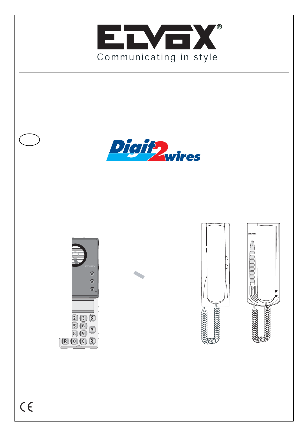
DIGITAL 2-WIRE SYSTEM ”Digit 2 Wires”
WITH ELECTRONIC UNIT Type 12B2
FOR SERIES 1200 PANEL WITH NUMERIC KEYPAD
Cod. S6I.12B.20E RL.00 11/2008
Il prodotto è conforme alla direttiva europea 2004/108/CE e successive.
Product is according to EC Directive 2004/108/CE and following norms.
INSTALLATION AND CONNECTION MANUAL
GB
POWER SUPPLY
PHONES
ELECTRONIC UNIT
TYPE 12B2
FOR SERIES 1200
PANELS
www.leedan.com info@leedan.com Toll-Free: 800-231-1414
®
832A
Page 2

2
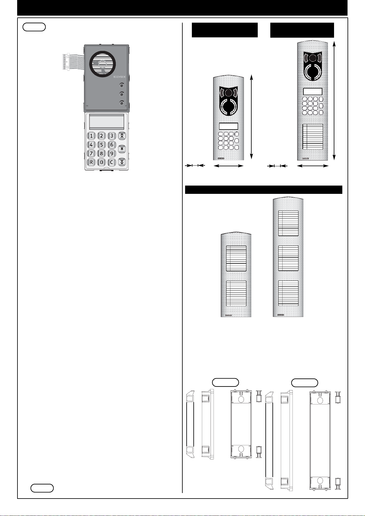
Electronic unit Type 12B2 for series 1200 panels
INTRODUCTION
With the Digit Digit 2 Wires electronic unit Type 12B2 it is possible to
build series 1200 audio panels with alphanumeric keyboard and display complete with 2-line, 16-character each, display.
The electronic units are to be used with series 1200 plates and
components, supplied separately.
Selection of the elements starts with the plate for the standard electronic unit, continuing with the addition of any extra plates that make it
possible to expand the standard modules. To complete the panel, the
box and frame versions are selected according to the type of panel
installation; surface wall-mounted or flush-mounted.
DESCRIPTION
Type 12B2 corresponds to the electronic unit for building an electronic
audio plate with alphanumeric keyboard and display.
This unit provide the facility to create exclusively audio door entry installations with only 2 polarised wires to the cable riser.
The entrance panels are designed to operate either alone or together
with other entrance panels by interconnecting the specific terminal
boards; a maximum of 2 additional panels can be connected in parallel
with the main panel by adding one additional wire from one entrance
panel to the next. (no more than 3 panels per installation).
Electronic entrance panels can also generate different call codes by
means of the numerical keypad, with values from 1 to 9999. A maximum
of 200 users can be configured in the system.
Facility to connect one interphone to another interphone with the same
call (max. 2 interphones connected in parallel).
The front of the panels feature "External Volume - 2", "Internal Volume
- 3" and "Audio Balance - 1" controls, which are preset in the factory. If
necessary we recommend exclusively adjustment of "External Volume"
and, if necessary, adjustment of "Balance" in the case of feedback on
the speech unit, turning the specific trimmer slightly clockwise or anticlockwise until the feedback howl is eliminated. In addition, the entrance panel can be programmed directly from the keypad for the technical
parameters programming phase.
INSTALLATION
The assembling and the installation of the electronic units for the 1200
series plates require the following phases:
1- Define the plate for the electronic base unit and possible additional
plates (see components on page 3).
2- Define the back boxes and the frames for the surface wall-mount or
flush-mount installation (see accessory on page 4).
3- Install the flush-mounted wall box or surface-mounted wall box at
suitable height. Route the wires through the hole at the bottom of the
box.
4- Fix the rainproof cover on the back box.
5- Fix the terminal box of the base module to the module holder frame
of the entrance panel.
6- Connect the terminal block to the system as shown in the wiring dia-
gram.
7- Fix the module holder frame to the back boxes
8- Connect the electronic unit of the base module to the plates with
name-tags.
9- Insert the electronic unit and the additional modules in the module
holder frame of the entrance panel.
10-Insert the microphone of the electronic base unit in the module hol-
der frame of the entrance panel (Fig. 8, Part 1).
11- Program the entrance panel.
12- Insert the external plate of the electronic unit in the module holder
frame and the additional entrance panels in the remaining module
holder frames.
13- Close the panel
BASIC MODULES
The basic modules comprise: an electronic unit and a connection terminal block. The electronic unit is equipped with a speech unit, a backlit
alphanumeric display, a keypad, and wiring for connecting the terminal
block.
SAFETY INSTRUCTIONS / INTRODUCTION
SAFETY INSTRUCTIONS FOR INSTALLERS
- Carefully read the instructions on this leaflet: they give important information on the safety, use and maintenance of the installation.
- After removing the packing, check the integrity of the set. Packing
components (plastic bags, expanded polystyrene etc.) are dangerous
for children. Installation must be carried out according to national safety regulations.
- It is convenient to fit close to the supply voltage source a proper bipolar type switch with 3 mm separation (minimum) between contacts.
- Before connecting the set, ensure that the data on the label correspond to those of the mains.
- Use this set only for the purposes designed, i.e.for electric door-opener systems. Any other use may be dangerous. The manufacturer is not
responsible for damage caused by improper, erroneous or irrational
use.
- Before cleaning or maintenance, disconnect the set.
- In case of failure or faulty operation, disconnect the set and do not
open it.
- For repairs apply only to the technical assistance centre authorized by
the manufacturer.
- Safety may be compromised if these instructions are disregarded.
- Do not obstruct opening of ventilation or heat exit slots and do not
expose the set to dripping or sprinkling of water.
- Installers must ensure that manuals with the above instructions are left
on connected units after installation, for users' information.
- All items must only be used for the purposes designed.
WARNING: to avoid the possibility of hurting yourself, this unit must be
fixed to the wall according to the installation instructions.
- This leaflet must always be enclosed with the equipment.
Directive 2002/96/EC (WEEE)
The crossed-out wheelie bin symbol marked on the product indicates that
at the end of its useful life, the product must be handled separately from
household refuse and must therefore be assigned to a differentiated collection centre for electrical and electronic equipment or returned to the
dealer upon purchase of a new, equivalent item of equipment.
The user is responsible for assigning the equipment, at the end of its life,
to the appropriate collection facilities.
Suitable differentiated collection, for the purpose of subsequent recycling
of decommissioned equipment and environmentally compatible treatment and disposal, helps prevent potential negative effects on health and
the environment and promotes the recycling of the materials of which the
product is made. For further details regarding the collection systems
available, contact your local waste disposal service or the shop from
which the equipment was purchased.
Risks connected to substances considered as dangerous (WEEE).
According to the WEEE Directive, substances since long usually used on
electric and electronic appliances are considered dangerous for people
and the environment. The adequate differentiated collection for the subsequent dispatch of the appliance for the recycling, treatment and
dismantling (compatible with the environment) help to avoid possible
negative effects on the environment and health and promote the recycling of material with which the product is compound.
www.leedan.com info@leedan.com Toll-Free: 800-231-1414
Page 3
3
COMPONENTI
3
2
1
Electronic unit
Art. 12B2
Controls:
Fig. 2
1 - Balance
2 - External volume
3 - Internal volume
Fig. 3
TERMINAL
BLOCK
TERMINAL BLOCK
The terminals of the circuit board are located on another printed circuit
connected to the entrance panel by means of a 20-pin connector (see
Fig. 3).
N.B.: Observe the correct polarity when connecting the digital bus.
Refer to the wiring diagrams given on the following pages.
The board with the connection terminal block is also equipped with two
jumpers designated BL1 and BL2 with jumpers installed.
Remove the jumpers to increase immunity to disturbance.
The board has also a fixed "LOAD" jumper. The jumper must be retained
with a single entrance panel while with several entrance panels connected in parallel (maximum three) it should be left intact on just one of the
entrance panels, while it must be severed on the other entrance panels.
Wiring for terminal block
connection
396
100
100
282
Art. 122N
Art. 123N
22
22
Art. 122D Art. 123D
Terminal Description
-S2 Direct electric lock control
(- 12 V).
+S1 Direct electric lock control
(+ 12 V).
AC Power supply
(from transformer Art. 832A).
AC Power supply
(from transformer Art. 832A).
TU Not used.
+5 + 5V output.
TRX Communication line for test.
- Ground.
PB Additional pushbutton
for lock control.
PA Additional pushbutton
for lock control.
+12 + 12Vdc output for services
(supplementary modules power supply)
F2 Not used
F1 Not used
CH Connection line for door call pushbutton.
LO Line for "engaged" signal
for configurations with several panels
connected in parallel.
L2 Digital bus (2 wires) to interphone cable
riser (-16Vdc).
L1 Digital bus (2 wires) to interphone cable
riser (+16Vdc).
Fig. 4A
Fig. 4B
HEIGHT OF 2-MODULE
ENTRANCE PANELS
HEIGHT OF 3-MODULE
ENTRANCE PANELS
SUPPLEMENTARY PUSH-BUTTON PANELS
ACCESSORIES: BACK BOXES MODULE-HOLDER FRAMES
Width of back boxes 88 mm for 1 horizontal module and depth 50 mm.
Type 9092
For 2 additional modules.
Height: 2 vertical modules
(248 mm)
Type 9093
For 3 additional modules.
Height: 3 vertical modules
(360 mm)
www.leedan.com info@leedan.com Toll-Free: 800-231-1414
Page 4

4
ACCESSORIES
1P21 1P22 1P23 1P24
for 1 panel for 2 panels for 3 panels for 4 panels
2 modules high alta 2 moduli 2 modules high 2 modules high
RAINPROOF COVERS
1E21 1E22 1E23 1E24
for 1 panel for 2 panels for 3 panels for 4 panels
2 modules high alta 2 moduli 2 modules high 2 modules high
SURFACE-MOUNTED BOXES WITH RAINPROOF COVER
124 front side 224 front side 324 front side 424 front side
120 rear side 220 rear side 320 rear side 420 rear side
124 front side 224 front side 324 front side 424 front side
120 rear side 220 rear side 320 rear side 420 rear side
124 front side 224 front side 324 front side 424 front side
120 rear side 220 rear side 320 rear side 420 rear side
124 front side 224 front side 324 front side 424 front side
120 rear side 220 rear side 320 rear side 420 rear side
1E31 1E22 1E23 1E24
for 1 panel for 2 panels for 3 panels for 4 panels
3 modules high 3 modules high 3 modules high 3 modules high
1P31 1P32 1P33 1P34
for 1 panel for 2 panels for 3 panels for 4 panels
3 modules high 3 modules high 3 modules high 3 modules high
www.leedan.com info@leedan.com Toll-Free: 800-231-1414
295
410
297
39,5
412
39,5
295
410
297
74
412
74
Page 5
5
Fig. 5
Fig. 6
Fig. 7
Fig. 8
part. 1
Fig. 8B
Fig. 8A
INSTALLATION
FLUSH-MOUNTED ENTRANCE PANEL INSTALLATION WITH RAINPROOF COVERS.
Assembly of flush-mounted entrance panel requires the use of the flushmounted back boxes type 9092 (9192), 9093 (9193) respectively for 2
or 3 electronic modules mounted vertically (Fig. 4A and 4B).
If the entrance panel uses more than one flush-mounted back box, the
rainproof covers must also be used (see ALPHANUMERIC DISPLAY
plates: accessories on page 4, series 1Pxx), according to the number of
modules fitted vertically or horizontally.
Note: Back boxes type 9092 and 9192 or 9093 and 9193 cannot be matched between them but only between: 9092 with 9092, 9192 with 9192
or 9093 with 9093 and 9193 with 9193.
Warning: during installation of back box type 9192 it is necessary to
insert the cover supplied in order to avoid possible deformations of the
box itself
Installation:
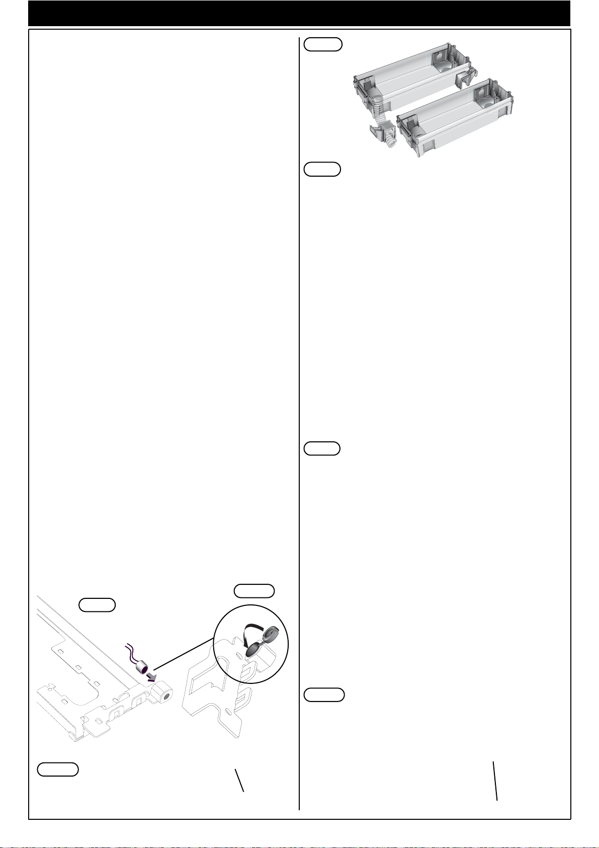
- If the installation requires a combination of several back boxes, use
the hooks supplied with the back boxes to secure them together (Fig.
5).
- Install the flush-mounted wall box or surface-mounted wall box at suitable height.
- Fix the terminal block of the electronic unit on the module holder
frame by means of the screws supplied (Fig. 6).
- Fix the rainproof cover to the flush-mounted back box using the
screws supplied (Fig. 6).
- Fix the module holder frames to the frames and the back boxes (Fig.
6).
- Connect the terminal box of the electronic unit to the system.
- Connect the terminal block of the electronic unit by means of the
wiring on the upper section.
- Connect the additional modules, if any, and insert them.
- Insert the electronic unit.
- Insert the microphone in the lower right section of the frame (Fig. 8).
Pay attention that the microphone cables are inserted in the
external slot of the electronic module (Fig. 8A, 8B).
- Close the entrance panel, attaching the plate first from the upper section and then securing the lower section by means of the special key
on the head section
- Perform the programming phases (see page 7).
SURFACE WALL-MOUNTED ENTRANCE PANEL INSTALLATION
Assembly of the surface wall-mounted entrance panel requires the use
of the back boxes series 1Exx.
Installation:
- Fix the electronic unit terminal block under the module holder frame
by using the screw provided (Fig. 8).
- Fix the module holder frames to the frame and back boxes (Fig. 7).
- Connect the terminal block of the electronic unit to the system.
- Connect the electronic unit to the terminal block by means of the cable
present on the upper section (Fig. 2).
- Connect the additional modules, if any, and insert them.
- Insert the electronic unit.
- Insert the microphone in the right lower side of the module holder
frame (Fig. 8).
Pay attention that the microphone cables are inserted in the
external slot of the electronic module (Fig. 8A, 8B).
- Insert the module plates in the module holder frames (Fig. 8).
- Close the entrance panel, attaching the plate first from the upper sec-
tion and then securing the lower section by means of the special key
on the head section.
- Perform the programming phases (see page 7).
Microphone cable
Electronic unit without module holder frame
Electronic unit with module holder frame
Microphone cable
www.leedan.com info@leedan.com Toll-Free: 800-231-1414
Page 6

6
INSTALLATION POWER SUPPLY AND PHONES
Fig. 21
Fig.23
Fig. 22
Fig. 23
Art. 887D - 887D/A
Art. 6220/A
DESCRIPTION OF INTERPHONES
"Digit 2 Wires" interphones Art. 887D, 887D/A form part of the 8870
series, while interphone Art. 6220/A belongs to the PETRARCA series.
The 8870 series Digit 2 Wires interphone is supplied in the version with
one lock release pushbutton and a dedicated call speaker. Call volume
can be decreased by shifting the speaker connector from position A+ to
position A-.
The interphones are prearranged for wall mounting and/or desktop
installation (interphones Art. 887D, 887D/A are wall-mounting only, while
interphone Art. 6220/A is suitable for wall mounting or, after fitting a specific support base, desktop installation).
N.B.: When a call is made from the entrance panel the voice signal is
inhibited until the end of the sequence of ringtones or until the handset
is picked up between one ringtone and another. Programming of the call
code associated with the interphone is performed by means of 8 jumpers
that are used to distinguish a given interphone from the other interphones in the system.
Installation instructions
Fig. 21 - Open the interphone and separate the cover from the base by
prising the bottom side of the cover.
Fig. 22 - To separate the base of the interphone from the cover, insert a
crosshead screwdriver in the central location and turn it until the cover
clicks off.
Fig. 23 - Fix the interphone to a rectangular, vertical wall-box previously
installed in a wall recess by means of the 2 screws supplied, or fix the
screws directly to the wall using ø5mm expansion plugs. Make the connections to the terminals. The interphone should be fixed so that the top
is at a height of about 1.5 m from the floor.
POWER SUPPLY UNIT INSTALLATION
Before connecting the system use a normal tester to check for possible
open circuits or short circuits of the wires; it is good practice to route the
entry system wires through specific electrical conduits separately from
mains power wires and other sources of disturbance.
Transformer Art 832A must be installed in a dry and clean location well
clear of heat sources. Ensure the transformer installation location is easily accessible in order to facilitate checking and set-up procedures.
Secure the transformer to the wall by means of the supplied screw
anchors, or install it in a specific panel with top-hat section DIN rail.
DESCRIPTION OF POWER SUPPLY UNIT Art. 832A
The power supply unit utilised for "Digit 2 Wires" series systems is transformer Art. 832A. The transformer supplies one entrance panel,
pushbutton illumination system, door lock and 200 interphones. A high
consumption lock or timer-controlled lock calls for the use of a second
transformer Art. 832/030 and relay Art. 170/001 to be connected to the
system according to diagram SI518. The transformer is equipped with a
19Vac low voltage output with maximum power rating of 30VA; the transformer features thermal and short-circuit protection by means of a PTC
(type SIEMENS C850). The transformer requires a power supply of 230V
(+6%, -10%) 50-60Hz. Alternative voltages are possible on demand.
N.B.: if the system is equipped with two or three entrance panels, install
a transformer for each entrance panel, keeping the wires connecting
each transformer to the respective entrance panel separate from the
other wires.
www.leedan.com info@leedan.com Toll-Free: 800-231-1414
Page 7

7
Press keys R-4, enter the password, then press key (down arrow)
to enter key programming mode. Press key C to display the various numbers. The position number is shown on the first line, while the second line
shows the key code, which can be edited. Press key C both after editing
the code and to scroll through the numbers. When programming is completed mode press key R. A maximum of 200 different door lock release
codes con be programmed.
Hardware-software codification of numbers
The numbers to be entered to call an interphone can be edited. The hardware number is the number physically set on the interphone by means
of the jumpers. The default software number is the same as the hardware number. The software number to be entered to make a call can be set
to a different address from the physical hardware. The new number can
have a maximum of 4 digits. To configure a different logic of the interphone numbers (for example, in a hotel rooms on the first floor may be assigned numbers starting with 1: 1001, 1002, ... numbers corresponding to
interphones on the second floor can be assigned numbers starting with
2: 2001, 2002, ...). To perform this codification enter the programming
function with the normal procedure (press R-4 and enter the password)
then press key (up arrow) to enter HW-SW numbers programming
mode. Press key C to display the various numbers. The HW number is
shown on the first line while the second line shows the editable SW number. Press key C after editing and to scroll between numbers.
When programming is terminated press key R. To enable this numbering
instead of the direct system (number entered = interphone HW code
number), enter parameters progamming mode and set the "Enable
Software N." parameter to 1.
When the software numbers are modified the entrance panel will check
whether the number entered exists already as both a hardware code and
a software code and, if it finds any matches it will signal that the procedure cannot be performed.
For example, if you attempt to replace a software code with number 5,
which is already present, the entrance panel will respond with:
NUMBER ALREADY IN THE MEMORY
followed by the message:
when this message is displayed, change the software number.
The maximum number of interphones that can be encoded is 200.
ERR_N_HW= 005
ERR_N_SW= 0005
OPERATION
With the entrance panel in standby (without any specific signals on the
display) enter the number of the interphone to call and press key C to
confirm or key R to re-enter the number. Once key C is pressed the engaged signal is transmitted to the entrance panels in parallel and the call is
activated. The number of ringtones is programmable. If the handset is lifted between one ringtone and the next, the ringtones are interrupted and
the voice circuit is activated immediately. If the door lock is released or a
door call is made, the voice circuit is inhibited for approximately 2
seconds to prevent acoustic feedback on the entrance panel, after which
it is reactivated. Before reactivating the voice circuit a check is carried out
to ensure the user has not hung up the handset, in which case the conversation is terminated.
DESCRIPTION OF FUNCTIONS
Parallel engaged
With the entrance panel in standby, if another entrance panel in parallel
makes a call, the LO line is set to low voltage level by the calling entrance panel. The entrance panel in standby indicates that the panel is engaged with a message on the display, and disables the keypad. In the case
of a lock pulse from an interphone, if the "Lock Mode" parameter of the
engaged panel is active and set to 2, the lock is opened. At the end of
conversation on the active panel the LO line is returned to high voltage
level and the panel in standby clears the "engaged" message from the
display and re-enables the keypad.
Lock signal
The lock signal is activated from the interphone by means of a pushbutton. The following processes are performed.
1) The lock is activated for the set time
2) In the case of an active entrance panel, the interphone is disconnected to avoid acoustic feedback howl on the entrance panel, and then
after approximately 2 seconds communication between interphone
and entrance panel is restored.
Door lock release from an entrance panel
To release the lock directly from the entrance panel press keys R-1 simultaneously then enter the 8-digit password (from 1 to 99999999) previously programmed by accessing technical parameters with keys R-4. If the
entrance panel is engaged it is anyway able to release the lock it controls, after which it returns to engaged status. To program door lock release codes perform the following procedure.
OPERATION AND DESCRIPTION OF FUNCTION
N. Name Default
Value
Minimum
value
Maximum
value
Description
1 PASSWORD 123 1 99999999 Password to enter technical programming mode
2 ------ Not used
3 LANGUAGE ENGLISH 0 0 1 Indicates the language used for technical parameters and messages on the
display (Italian=0 English=1)
4 T LOCK 1 1 255 Lock activation time in seconds.
N.B.: Increasing the activation time to a value of more than 5 seconds is only
possible by installing an auxiliary relay Art. 170/001 and relative power supply transformer Art. 832/030.(Connection variant Ref. SI518).
5 LOCK MODE 1 1 2 This parameter is set to 1 by default (open only if the entrance panel is in
conversation). If set to 2 an entrance panel engaged by another entrance
panel can anyway release the lock (Art.8B62, 8B63 and 12B2 only)
6 CALLS No. 3 1 3 Indicates the number of calls to the interphone
7 CONVERSATION T 120 1 255 Conversation time in seconds
8 ANSWER T 30 1 255 Enables programmed numbering of interphones (by setting to 1). If set to 1
direct numbers are not enabled (if no SW number is found the direct call is
not made)
9 ENABLE SW No. 0 0 1 Abilita la numerazione programmata dei citofoni (impostando a 1)
Se si imposta a 1 i numeri diretti non sono abilitati (se non trova un numero
SW non chiama il diretto)
10 TRANSFER RINGTONE
TO ENTRANCE PANEL
1 0 1 If set to 1 the call tone can be heard on the entrance panel, otherwise the
call tone is not transferred
11 ENABLE DEBUG 1 0 1 Enables messages
ENTRANCE PANEL TECHNICAL PARAMETERS
Press R and 4 simultaneously on the entrance panel keypad to enter technical parameters programming mode. Then enter the password and press
C. The message "PROGRAM" is displayed, Press C again to display the parameters as shown in the following table.
PROCEDURE TO RESTORE DEFAULT PARAMETERS AND PASSWORD
Press and release the reset button (under the panel, near the microphone), then hold down buttons , , until the message "Default
Parameters" appears. This serves to restore standard technical parameters, resetting passwords and deleting software numbers.
If you do not know the password to enter technical parameters programming mode, proceed as described below to change the password.
www.leedan.com info@leedan.com Toll-Free: 800-231-1414
Page 8

8
INTERPHONES PROGRAMMING
The interphones must be programmed at the time of installation and connection.
Programming serves to distinguish between the interphones installed (from 1 to max. 200).
Physical programming of interphones
Interphones are programmed using the 8 jumpers located in the 8 locations (1, 2, 4, 8, 16, 32, 64, 128) in the interphones. Numbers from 1 to 200
can be entered by means of the jumpers. (See the tables on the following pages).
Jumper not connected
Jumper connected
PROGRAMMING OF INTERPHONES
INTERPHONE NUMBERS PROGRAMMING TABLE
www.leedan.com info@leedan.com Toll-Free: 800-231-1414
Page 9

9
INTERPHONE NUMBERS PROGRAMMING TABLE
Jumper not connected
Jumper connected
PROGRAMMING OF INTERPHONES
www.leedan.com info@leedan.com Toll-Free: 800-231-1414
Page 10

10
*
88888888
8
7
R
0
4
1
2
5
9
C
3
6
INTERPHONES CABLE RISER
Mais
Phone
Art. 887D
Phone
Art. 887D
Transformer
Art. 832A
Phone
Art. 887D
Phone
Art. 887D
C0
Conductors Ø fino a 50 m Ø fino a 100 m Ø fino a 200 m
AC, AC,
+S1, -S2
0,75 mm² 1 mm² 1.5 mm²
1 - 2 - L0 0,25 mm² 0,25 mm² 0,35 mm²
MINIMAL CONDUCTOR SECTION (mm2)
WIRING DIAGRAM
SINGLE CONDO AUDIO DOOR ENTRY SYSTEM WITH
ONE ENTRANCE PANEL.
Ref. Diagram SI515.
C0- External panel series 1200 with plate Art. 122D 123D
E1- Connection terminal block
E2- Electronic unit Art. 12B2
L- Electric lock 12V A.C.
P- Additional push-button for lock
www.leedan.com info@leedan.com Toll-Free: 800-231-1414
21
1
2
3
1
2
3
12
1
2
3
1
2
3
CO
E2 E1
LOAD
L1
L2
L0
CH
F1
F2
+12
PA
PB
-
TRX
+5
TU
AC
AC
+S1
-S2
PRI
190
P
L
Page 11

11
1
3
2
12
21
190
PRI
1
3
2
-S2
PA
PB
TRX
-
+12
TU
AC
AC
+S1
+5
L2
L1
CH
F2
F1
L0
6B
6A
6B
6A
1
3
2
1
3
2
6B
6A
6B
6A
L
P
KK
KK
E2 E1
CO
*
88888888
8
7
R
0
4
1
2
5
9
C
3
6
LOAD
Mais
Phone
Art. 887D/A
Phone
Art. 6220/A
Transformer
Art. 832A
Phone
Art. 887D/A
Phone
Art. 6220/A
C0
*
88888888
8
7
R
0
4
1
2
5
9
C
3
6
Phone
Art. 887D
Mais
Phone
Art. 887D
Transformer
Art. 832A
Phone
Art. 887D
Phone
Art. 887D
C0
CONDO SYSTEM WITH ONE ENTRANCE PANEL AND
CABLE RISER FOR INTERPHONE WITH DOOR CALL
PUSHBUTTONS. Ref. Diagram SI516.
WIRING DIAGRAM
CONDO SYSTEM WITH ONE ENTRANCE PANEL,
INTERPHONES ART. 6220/A AND ART. 887D/A AND
DOOR CALL PUSHBUTTONS. Ref. Diagram SI521.
INTERPHONES CABLE RISER
INTERPHONES CABLE RISER
C0- External panel series 1200 with plate Art. 122D 123D
E1- Connection terminal block
E2- Electronic unit Art. 12B2
K- Outdoor call push-button
L- Electric lock 12V A.C.
P- Additional push-button for lock
C0- External panel series 1200 with plate Art. 122D 123D
E1- Connection terminal block
E2- Electronic unit Art. 12B2
K- Outdoor call push-button
L- Electric lock 12V A.C.
P- Additional push-button for lock
www.leedan.com info@leedan.com Toll-Free: 800-231-1414
21
CH
1
2
3
KK
1
2
3
KK
12
CH
1
2
3
1
2
3
PRI
190
L1
L2
L0
CH
F1
F2
+12
PA
PB
-
TRX
+5
TU
AC
LOAD
AC
+S1
-S2
CO
E2 E1
P
L
Page 12

12
*
88888888
8
7
R
0
4
1
2
5
9
C
3
6
*
88888888
8
7
R
0
4
1
2
5
9
C
3
6
*
88888888
8
7
R
0
4
1
2
5
9
C
3
6
Transformer
Art. 832A
Transformer
Art. 832A
Transformer
Art. 832A
Mais
Phone
Art. 887D
Phone
Art. 887D
Mais Mais
C0- External panel series 1200
with plate Art. 122D 123D
E1- Connection terminal block
E2- Electronic unit Art. 12B2
L- Electric lock 12V A.C.
P- Additional push-button for lock
Phone
Art. 887D
Phone
Art. 887D
C0
C0 C0
WIRING DIAGRAM
CONDO SYSTEM WITH MORE THAN ONE ENTRANCE PANEL IN PARALLEL (MAXIMUM 3 PANELS).
Ref. Diagram SI517.
In the case of several entrance panels connected in parallel (up to three entrance panels) the "LOAD" jumper on the board of the
connection terminal block must remain intact on one entrance panel while it must be severed on the others.
INTERPHONES
CABLE RISER
www.leedan.com info@leedan.com Toll-Free: 800-231-1414
21
1
2
3
1
2
3
1
2
3
12
PRI
1
2
3
PRI
PRI
CO
190
E2 E1
LOAD
L1
L2
L0
CH
F1
F2
+12
PA
PB
TRZ
+5
TU
AC
AC
+S1
-S2
P
-
CO
L
190
E2 E1
LOAD
L1
L2
L0
CH
F1
F2
+12
PA
PB
-
TRX
+5
TU
AC
AC
+S1
-S2
190
L1
L2
L0
CH
F1
F2
LOAD
+12
PA
PB
-
TRX
+5
TU
AC
AC
+S1
-S2
P
L
P
CO
E2 E1
L
Page 13

13
*
88888888
8
7
R
0
4
1
2
5
9
C
3
6
*
88888888
8
7
R
0
4
1
2
5
9
C
3
6
*
88888888
8
7
R
0
4
1
2
5
9
C
3
6
Transformer
Art. 832A
Transformer
Art. 832A
Transformer
Art. 832A
Mais
Phone
Art. 887D
Phone
Art. 887D
Mais Mais
C0- External panel series 1200
with plate Art. 122D 123D
E1- Connection terminal block
E2- Electronic unit Art. 12B2
K- Outdoor call push-button
L- Electric lock 12V A.C.
P- Additional push-button for lock
Phone
Art. 887D
Phone
Art. 887D
C0
C0
C0
WIRING DIAGRAM
CONDO SYSTEM WITH MORE THAN ONE ENTRANCE PANEL IN PARALLEL (MAXIMUM 3 PANELS) AND
CABLE RISER FOR INTERPHONE WITH DOOR CALL PUSHBUTTONS.
Ref. Diagram SI551.
In the case of several entrance panels connected in parallel (up to three entrance panels) the "LOAD" jumper on the board of the
connection terminal block must remain intact on one entrance panel while it must be severed on the others.
INTERPHONES
CABLE RISER
www.leedan.com info@leedan.com Toll-Free: 800-231-1414
21
CH
1
2
3
1
2
3
1
2
3
KK
1
2
3
KK
12
CH
PRI
PRI
PRI
CO
190
L1
L2
L0
CH
F1
F2
+12
E2 E1
PA
PB
-
TRZ
+5
TU
AC
LOAD LOAD LOAD
AC
+S1
-S2
P
CO
L
190
E2 E1
L1
L2
L0
CH
F1
F2
+12
PA
PB
TRZ
+5
TU
AC
AC
+S1
-S2
190
L1
L2
L0
CH
F1
P
CO
E2 E1
-
L
F2
+12
PA
PB
-
TRZ
+5
TU
AC
AC
+S1
-S2
P
L
Page 14

14
Phone
Art. 887D
Phone
Art. 887D
Phone
Art. 6220/A
Phone
Art. 6220/A
Phone
Art. 887D/A
Relay
Art. 170/101
Relay
Art. 170/101
Relay
Art. 170/101
Phone
Art. 887D/A
Variant for connection of call repeater Art. 2/841 with
interphones Art. 887D with or without door call.
Variant for connection of call repeater Art. 2/841 with
interphones Art. 887D and Art. 6220/A with door call.
Variant for connection of supplementary doorbell with
interphones Art. 887D with or without door call.
Variant for connection of supplementary doorbell
with interphones Art. 887D/A and Art. 6220/A with
door call.
K- Outdoor push-button
Bell supply
(do not use the door
entry panel transformer)
Bell supply
(do not use the door
entry panel transformer)
Bell supply
(do not use the door
entry panel transformer)
Call repeater
Art. 2/841
Call repeater
Art. 2/841
Call repeater
Art. 2/841
Additional
bell
Additional
bell
Additional
bell
K- Outdoor push-button
www.leedan.com info@leedan.com Toll-Free: 800-231-1414
2
3
5
6
1
2
3
6A
6B
2
3
5
6
1
2
3
K
+
1C
RC
342515
1
2
3
+
1C
1
2
3
6A
6B
RC
342515
K
6A
6B
2
3
5
6
1
2
3
K
+
-
1
2
3
6A
6B
1C
RC
342515
K
Page 15

15
*
88888888
8
7
R
0
4
1
2
5
9
C
3
6
Mais
Transformer
Art. 832A
C0- External panel series 1200
with plate Art. 122D 123D
E1- Connection terminal block
E2- Electronic unit Art. 12B2
E4- Additional module Art. 122N, 123N
Art. 122N (2 modules), 123N (3 modules)
P- Additional push-button for lock
L- Electric lock 12V A.C.
*
88888888
8
7
R
0
4
1
2
5
9
C
3
6
Mais
Transformer
Art. 832A
Mais
Alimentatore
Art. 6582
C0
C0
CONNECTION VARIANTS FOR SUPPLEMENTARY MODULES ART. 122N AND 123N (REF. SI519).
CONNECTION FOR SUPPLEMENTARY POWER SUPPLY UNIT ART. 6582
INTERPHONES
CABLE RISER
INTERPHONES
CABLE RISER
To other
additional modules
The additional power supply type 6582 is used to
power the LEDs for the name-tags lighting when
there are more than 8 additional name-tags
modules (type 122N, 2 module panel, 123N 3
module panel) . One power supply type 6582 can
power up to 65 modules of panel with name-tags
modules (122N with 2 modules, 123N with 3
modules).
www.leedan.com info@leedan.com Toll-Free: 800-231-1414
12
PRI
190
COE4CO
E2 E1
LOAD
E4
L1
L2
L0
CH
F1
F2
+12
PA
PB
-
TRX
+5
TU
AC
AC
+S1
-S2
P
-
+
-
+
L
12
PRI
190
L1
L2
L0
CH
E4
E4
E4
LOAD
F1
F2
+12
PA
PB
-
TRX
+5
TU
AC
AC
+S1
-S2
P
-
+
-
+
-
+
-
+
L
COE4CO
CO
E2 E1
PRI
+I-+U CAB D
Agli altri moduli supplementari
to other addictional module
Page 16

16
UNI EN ISO 9001
*
88888888
8
7
R
0
4
1
2
5
9
C
3
6
Mais
Transformer
Art. 832A
Mais
Transformer
Art. 832/030
C0- External panel series 1200
with plate Art. 122D 123D
E1- Connection terminal block
E2- Electronic unit Art. 12B2
P- Additional push-button for lock
L- Electric lock 12V A.C.
Q- Relè Art. 170/001
Relè
Art. 170/001
C0
WIRING DIAGRAM
CONNECTION VARIATION FOR LOCK WITH SUPPLEMENTARY POWER SUPPLY (REF. SI518).
To open high power consumption/timer-controlled locks, an external transformer can be installed to power the lock by means of a relay art.
170/001 connected to entrance panel terminals +S/-S.
INTERPHONES
CABLE RISER
www.leedan.com info@leedan.com Toll-Free: 800-231-1414
CO
E2 E1
LOAD
L1
L2
L0
CH
F1
F2
+12
PA
PB
TRZ
+5
TU
AC
AC
+S1
-S2
12
PRI
190
P
-
PRI
54321
150
L
 Loading...