

Elvira LORNET-24 User Manual

UULLTTRRAA--CCOOM
MPPAACCTT HHAANNDDHHEELLDD
NNOONN--LLIINNEEAARR JJUUNNCCTTIIOONN DDEETTEECCTTOORR
««L
L
O
O
R
R
N
N
E
E
T
T--2244»»
UUSSEERR MMAANNUUAALL
CCEERRTTIIFFIICCAATTE
E

2
UUSSEERR MMAANNUUAALL
1. Introduction
The ultra-compact non-linear junction detector “LORNET-24” (further NLJD) is used for
search and location of electronic devices both in active and switch-off state.
NLJD operation is based on the property of semiconductor components to generate a
response at the 2nd and 3rd harmonics when radiated by an UHF probing signal. Semiconductor
components of artificial origin will have a higher level second harmonic while semiconductor
components of natural origin (e.g. oxide films) will have a higher level third harmonic
respectively. NLJD analyzes the 2nd and 3rd harmonics response of the radiated objects, which
enables a quick and reliable identification of electronic devices and natural oxide
semiconductors.
NLJD automatically finds the best receiving frequency channel free of noise and distortion
providing flawless operation even in the complicated electromagnetic environment. The
frequency tuning algorithm implemented in NLJD automatically selects the probing signal
frequency such that the noise level in the 2nd harmonic receiving channel is held minimal, while
digital processing of a demodulated signal gives maximum sensitivity.
There are two types of radiated signals:
- continuous wave carrier (CW);
- pulse modulated carrier with a duty cycle 44 (pulse).
This enables to combine wide detection range and reliable identification of the devices
found.
The output power automatic control mode significantly simplifies operator’s work. NLJD
simultaneously displays the 2nd and 3rd harmonics levels at its LED panel. Besides, the 2nd and
3rd harmonics levels can be estimated in turn aurally by the click repetition rate reproduced
through a built-in loudspeaker or earphones connected to a pocket-size receiver.
A detector of the returned UHF signal envelope enables at to detect radio devices with
acoustic converter aurally at continuous frequency carrier radiation.
2. Specifications
2.1. Radiated signal types:
- continuous wave carrier;
- pulse modulated carrier with a duty cycle 44.
2.2. Carrier frequency step 2 MHz within a tuning range of (2406 … 2414) MHz.
Automatic frequency selection. Possibility of radiation at the carrier frequency with a minimum
noise level in the 2nd harmonic receiver path.
2.3. Maximum radiated power in the CW mode ≥ 0.2 W.
2.4. Peak radiated power in the pulse mode ≥ 10 W.
2.5. Manual or automatic control of the radiated power level.
Dynamic control range of 20 dB down from the maximum output power value with 11 level
gradations.
2.6. Receivers sensitivity better than –110 dBm (one LED lights up at the indicator scale).
2.7. Receivers tuning frequencies equal to the transmitter double and triple frequencies.
3
2.8. Receiving path dynamic range ≥ 24 dB (10 dB – LED indicator range, 14 dB – attenuator
adjusting range at receivers input).
2.9. Time of continuous operation with a lithium-Ion battery at the maximum radiated power:
- 3 hours in the pulse mode;
- 1.5 hours in the CW mode.
2.10. Equipped device weight ≤ 0.7 kg.
2.12. Operating conditions:
- ambient temperature 5…40°C.
- pressure 450 …800 mm of mercury
3. Delivery Set, Design and Accessories
3.1. The device includes units and accessories stated in the Table 1 below.
Table 1
No. Description Q-ty
1. A duplex antenna unit with a control panel and a built-in container for a
battery
1
2. Changeable Li-Ion batteries
2
3. A container for battery charging
1
4. A charger for a duplex unit battery
1
5. A receiver with an adapter to charge its battery and earphones
1
6. User Manual, Certificate
1
7. A package bag to keep and transport the device 1
Fig. 1
1
2
3 4
5
6 7

4
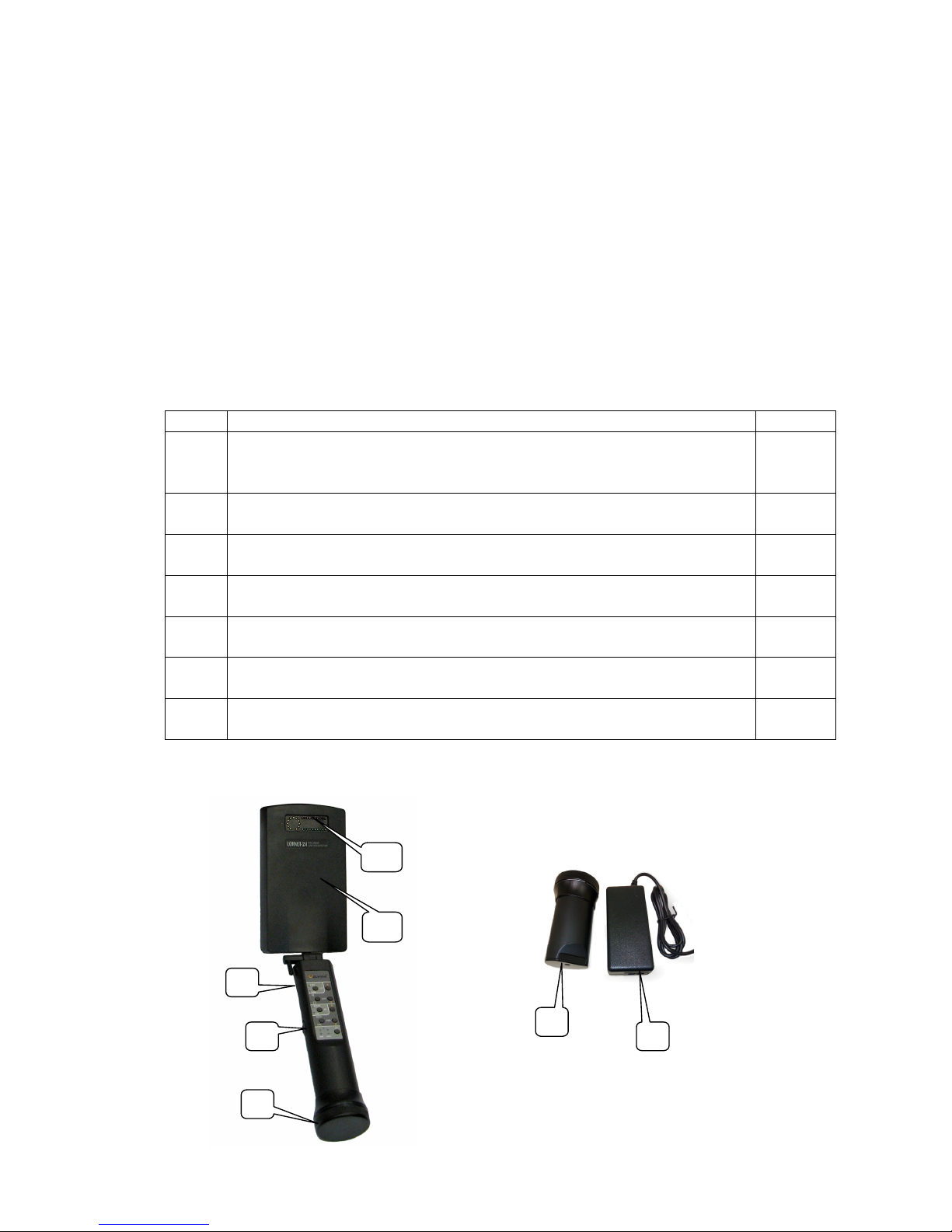
The appearance of the device is shown in Fig. 1, where:
1- LED indicators;
2- a duplex antenna unit;
3- a control panel;
4- a power switch;
5- a twisted cover of the battery section;
6- a container for battery charging;
7- a charger for a duplex unit battery.
Fig. 2
Fig. 2 shows a receiver, an adapter for charging its battery and earphones.
Note: A type and appearance of the charging adapter and earphones can be different from the
shown ones.
4. Purpose of NLJD Basic Units
4.1. The duplex antenna unit with LED indicators is used for:
• Analysis of distortion and interference in the instrument receiving path, which is made each
time the transmitter is switched on. Therefore, if an interfering signal appears during operation
(in a complicated electromagnetic environment) it is necessary to turn NLJD transmitter off
and on from time to time thus selecting an optimal frequency automatically, providing the best
sensitivity and detection range of semiconductor components.
• Generation UHF signal, receipt and digital processing of the 2nd and the 3rd frequency
harmonics. Simultaneous display of the 2nd and the 3rd harmonics levels gives the opportunity
to distinguish with a high reliability between signals of artificial semiconductors integrated in
electronic devices and natural corrosive ones which appear at oxidation of connecting points of
various metals.
• Demodulation of the 2nd and 3rd harmonics response, their amplification to the level required
for tapping both to earphones and a built-in loudspeaker. An operator can control sound
volume. An operator can listen to demodulated signals of the 2nd harmonic from lower or
upper receiver ranges in turn.
• Indication of the receiver power level and levels of the 2nd and 3rd harmonics of the signals
received (Fig. 3).
Fig. 3 LED Indicators
Transmitter
power
2-nd harmonic level
3-rd harmonic level
 Loading...