

Elverk 5KVA, 10KVA, 6KVA User Manual

ONLINE UPS
5/6/10kVA
USER MANUAL
UNINTERRUPTIBLE POWER SUPPLY UPS
ENGLISH
1
Table of Contents
1. Important Safety Instruction…………………………………………….. 2
1.1. An Important Notice…………………………………………………….. 2
1.2. Storage Instruction………………………………………………………. 4
2. Product Introduction…………………………………………………….. 5
2.1. General Characteristics………………………………………………….. 5
2.2. Symbols on the LCD Display Panel…………………………………….. 6
2.3. Panel explanation………………………………………………………... 9
2.4. Communication Port Explanation……………………………………….. 12
3. Installation and Operation……………………………………………….. 13
3.1. Unpacking……………………………………………………………….. 13
3.2. Selecting Installation Position……………………………………………14
3.3. Installation of Accessories Kit…………………………………………... 15
3.4. Terminal Block Explanation…………………………………………….. 16
3.5. Operation Test and Installation Instruction………………………………19
4. Troubleshooting Guide………………………………………………….. 30
4.1. Trouble Shooting…………………………………………………………30
5. Bundled Software Installation Guide……………………………………. 32
5.1. Hardware Installation……………………………………………………. 32
5.2. Software Installation…………………………………………………….. 32
6. Customer Options Slots…………………………………………………. 33
6.1. R2E(2nd RS-232 ) card…………………………………………………. 33
6.2. RSE(RS-485) card………………………………………………………. 33
6.3. USE(USB) card…………………………………………………………. 33
6.4. DCE(Dry Contact)-B card………………………………………………. 34
6.5. SNMP Cards…………………………………………………………….. 34
7. Specifications……………………………………………………………. 35

2
1 Important Safety Instruction
1.1. An Important Notice
1.1.1 For parallel system installation, please refer to parallel installation guide.
1.1.2 Because of “LITTLE LEAKAGE CURRENTS” generated by EMI Filter of
the UPS, it is necessary to double ensure if the earth of the UPS is properly
grounded before AC mains is connected with.
1.1.3 To ensure safety in all applications where a UPS is hard wired to the
Electrical Supply, ensure that the system is installed by a Qualified Electrical
Contractor.
1.1.4 The UPS has its own internal energy source (battery). Should the battery
be switched on when no AC power is available, there could be voltage at the
output terminals.
1.1.5 Make sure that the AC Utility outlet is correctly grounded.
1.1.6 Do not open the case, as there are no serviceable parts inside. Your
Warranty will be void.
1.1.7 Do not try to repair the unit yourself; contact your local supplier or your
warranty will be void.
1.1.8 Please make sure that the input voltage of the UPS matches the supply
voltage.
1.1.9 Use a certified input power cable with the correct plugs and sockets for
the appropriate voltage system.
1.1.10 To eliminate any overheating of the UPS, keep all ventilation openings
free from obstruction, and do not store "things" on top of the UPS. Keep the
UPS 30 cm away from the wall.
1.1.11 Make sure the UPS is installed within the proper environment as
specified. (0-40℃ and 30-90% non-condensing humidity)
1.1.12 Do not install the UPS in direct sunlight. Your warranty may be void if
the batteries fail.
1.1.13 Install the UPS indoors as it is not designed for installation outdoors.
1.1.14 Dusty, corrosive and salty environments can do damage to any UPS.
1.1.15 Install the UPS away from objects that give off excessive heat and areas
that are excessively wet.
1.1.16 If liquids are split onto the UPS or foreign objects dropped into the unit,
the warranty will be null and void.
1.1.17 The battery will discharge naturally if the system is unused for any
length of time.
1.1.18 It should be recharged every 2-3 months if unused. If this is not done,
then the warranty will be null and void. When installed and being used, the
batteries will be automatically recharged and kept in top condition.
1.1.19 This UPS supports electronic equipment in offices, telecommunications,
process control, medical and security applications. Non-authorized technician
is not allowed to install the UPS in the following areas.
3
a. Medical equipment directly related to human life
b. Elevator, Metro (Subway) system or any other equipment related to
human safety.
c. Public system or critical computer systems.
1.1.20 Do not install the UPS in an environment with sparks, smoke or gas.
1.1.21 Make sure the UPS is completely turned off when moving the UPS from
one place to another. It might cause electrical shock if the output is not cut
completely.
1.1.22 The UPS offers CVCF (Constant Voltage Constant Frequency) setting
function. To set RT series to be a CVCF shall be required by a qualified
technician.
a. For correct setting and wiring, please contact with your local agent.
b. Do not do it by yourself; otherwise, your warranty will be void.
1.1.23 This UPS has been designed and constructed to protect your assets
from the wide range of power aberrations experienced on Utility power lines
today. It is your insurance for reliable, clean and stable voltage supply. It is
worth taking care to install the system correctly and to have it maintained
correctly by your local dealer.
1.1.24 SAVE THESE INSTRUCTIONS - This Manual Contains Important
Instructions that should be followed during Installation and Maintenance of
the UPS and Batteries.
1.1.25 Intended for Installation in a Controlled Environment.
1.1.26 Disconnection Device - CAUTION - A disconnect switch shall be
provided by others for ac output circuit. To reduce the risk of fire, connect
only to a circuit provided with branch circuit over-current protection for 30
amperes for 6KVA and 40 amperes for 10KVA (see below details) rating in
accordance with the National Electric Code, ANSI/NFPA 70.
10Kva tower
Output No.
Output rating Ratings of output branch circuit
Over current protection
No.1 (L21-N21) 5 KVA, 120 V 45
No.2 (L22-N22) 5 KVA, 120 V 45
No.3 (L23-N22) 10 KVA, 208 V 50
No.4 (L21-N22) 10 KVA, 240 V 45

4
1.1.27 CAUTION - To reduce the risk of fire, unit input connect only to a circuit
provided with branch circuit over-current protection for 40 amperes for 6KVA
and 65 amperes for 10KVA rating in accordance with the National Electric
Code, ANSI/NFPA 70.
1.1.28 Use No. 10 AWG, 60°C copper wire and 22.1 lb-in Torque force when
connecting to terminal block.
1.1.29 The units are to be installed so that is not likely to be contacted by
people.
1.1.30 Maximum ambient operating temperature 40°C or equivalent.
1.2. Storage Instruction
For extended storage through moderate climate, the batteries should be
charged for 12 hours every 3 months by plugging the UPS power cord into the wall
receptacle and turn on input breaker on front panel. Repeat this procedure every 2
months under high temperature environment.
5
2 Product Introduction
2.1. General Characteristics
2.1.1 True online architecture continuously supplies in your critical device with a
stable, regulated, transient-free pure sine wave AC Power.
2.1.2 20KHz PWM sine-wave topology yields an excellent overall performance.
The high crest factor of the inverter handles all high-inrush current loads
without a need to upgrade the power rating.
2.1.3 Multi-functional LCD/LED panel may display various status of the UPS.
The LED display may show UPS working status, Utility Status and UPS
Abnormal status, in the mean while, the LCD display may show Input/Output
Voltage, Frequency, Load Status, Inner cabinet temperature, and Abnormal
Phenomenon.
2.1.4 To protect the unit from overloading, it automatically switches to bypass
mode in 160seconds, app 40msec if loading is at 105%~ 150% of rating and
in case of overloading at 150% of rating, it switches to bypass mode
immediately. It will automatically switch back to inverter mode once overload
condition ceases.
2.1.5 Should the output becomes short-circuit, the UPS holds the system and
cuts the output automatically till the short circuit situation is removed
manually.
2.1.6 Should the unit become overheated, the internal thermal Switch will detect
the heat and switch to bypass mode and vice versa.
2.1.7 Fully digitalized control circuit built in the UPS may upgrade the
functionality Of the UPS as well as reach a high-level protection of the UPS.
Through powerful Communication capability built, it enhances its ability for
remote control and monitoring easily.
2.1.8 Maintenance-free sealed-type battery minimizes after-sales service.
2.1.9 Providing four different working modes, such as Normal, ECO, CF50 and
CF60, it may widely be used in a variety of applications.
2.1.10 DC-start function makes sure of the start-up of UPS during power
outages.
2.1.11 Revolutionary battery management circuit analyzes battery discharging
status to adjust battery cut-off point and extend the life of batteries.
2.1.12 Intelligent temperature-controlled fan may not only extend the life of the
fan, but also reduce annoying noise because of sudden fan spin. It remains
your office quiet and comfortable as usual.
2.1.13 When UPS is out of order, you may read out the possible fault reason
from the LCD screen directly, which may reduce down unnecessary repair
task a lot.
2.1.14 When UPS is out of order, you may read out the possible fault reason
from the LCD screen directly, which may reduce down unnecessary repair
task a lot.
6
2.1.15 In case the UPS is out of order, Fault status will be shown on the LCD
screen
2.1.16 When the UPS is operated under CF50 or CF60 mode, the
recommended load connected shall be 75% of rated capacity if the input
voltage is 176~280Vac and 50% of the rated capacity if the input voltage is
160~280Vac
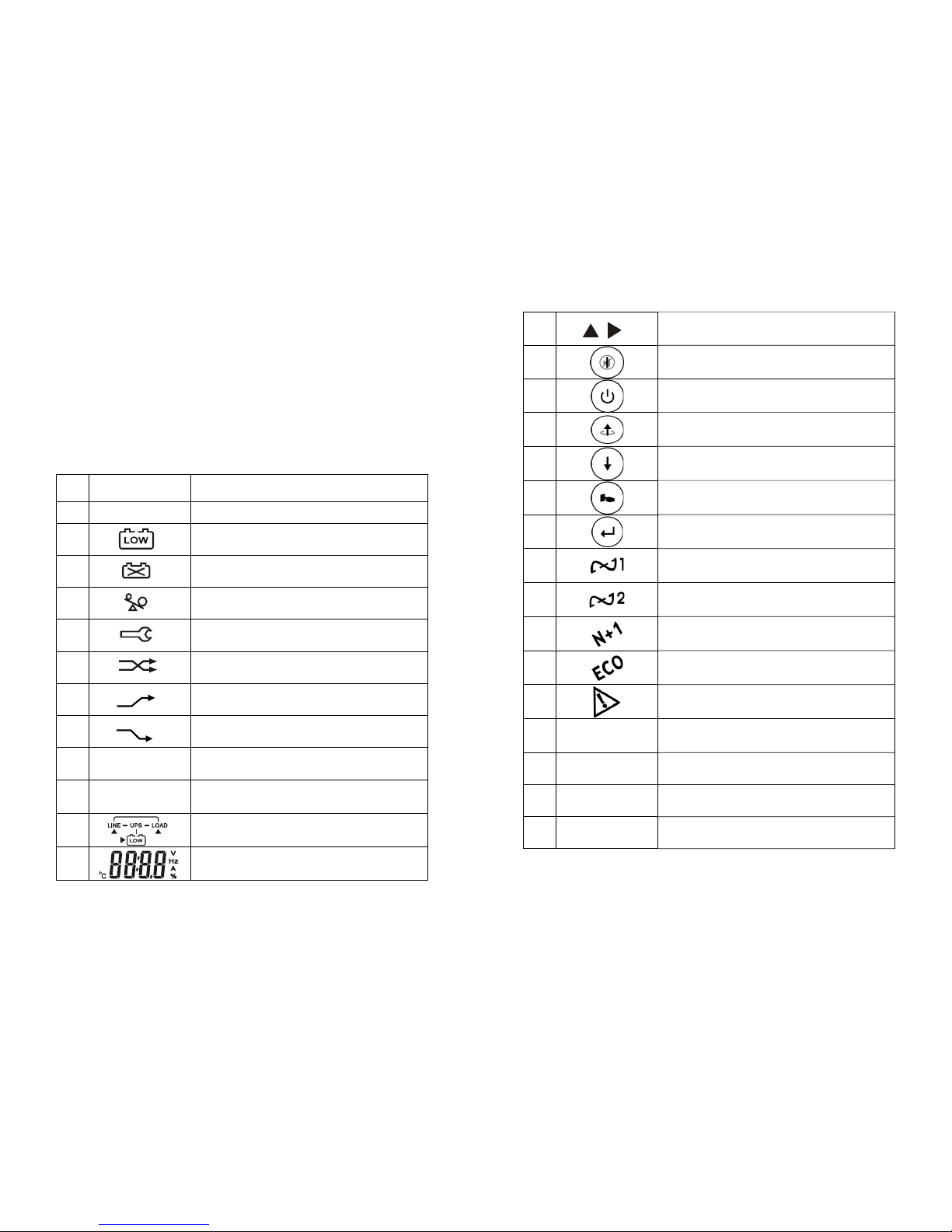
2.2. Symbols on the LCD Display Panel
Item Symbol Description
1 LINE
Utility or Bypass Source
2
Battery Low
3
Battery Abnormal
4
UPS Overloading
5
UPS Working in specified mode*
6
A Blackout Transfer occurred in UPS Output
7
Bypass Input Abnormal, UPS fails to transfer
to bypass, Bypass Abnormal at ECO mode
8
Utility Input Abnormal
9
OFF
UPS Shutoff
10
LINE OFF UPS Abnormal Lock
11
UPS Flow Chart
12
4 Digits Measurement Display
7
13
Indicate the item desired to be measured
14
UPS ON Switch or Alarm Silence
15
UPS OFF Switch
16
Previous Page or Setting Change
17
Next Page
18
Special Function Log in /out
19
Enter or Reconfirmed
20
Utility Input Normal LED
21
Bypass Input Normal LED
22
UPS under Redundancy Mode
23
UPS under ECO Mode
24
UPS Fault or Abnormal Warning LED
25
EPO
Emergency Power Off
26
Er05
Battery Weak or Dead
27
Er06
Output Short Circuit
28
Er10
Inverter Over-current
8
29
Er11
UPS Overheat
30
Er12
UPS Output Overloading
31
Er14
Fan Error
32
Er15
Wrong Procedure to Enter Maintenance Mode
33
Er16
Output Parameters Set Error in Parallel
System
34
Er17
ID Numbers are in conflict in Parallel System
or ID number Error in single unit
35
Er21
Parallel communication error ( communication
wire disconnected or failure to find ID1 UPS )
in parallel system
36
Er24
CVCF mode with Bypass input
37
Er27
The UPS must be operated in normal mode in
parallel system
38
Er28
Bypass Overload Time out and cut off output.
39
Er31
The settings of both control board and driver
board are not matched each other.
40
Er33
Isolated Transformer Overheat
41
Er**
Other Error code
*The specified modes include Normal mode, ECO mode, CVCF mode, etc..
9
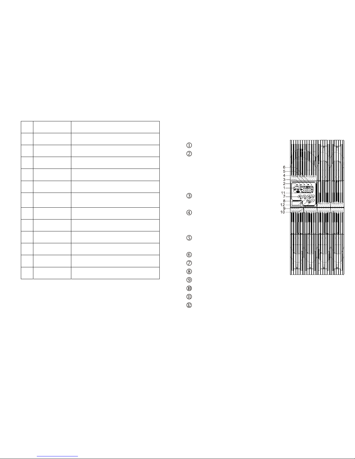
2.3. Panel explanation
2.3.1 Front Panel Function Explanations
LCD Display
Green LED steadily lights up to indicate that
the utility input voltage is within the window;
the LED flashes flickeringly to indicate that
the utility input voltage is within the
acceptable window
. Green LED lights up to indicate Bypass
Input is normal.
Green LED lights up to indicate the UPS
has the capability to run under redundancy
mode.
UPS is working under ECO ( Economic )
Mode
UPS fault or Abnormal
UPS ON/Alarm Silence
UPS OFF Switch
Special Functions log in/out
Go to next page
Go to Previous page or change the setting of the UPS
To reconfirm the change of UPS Setting
10
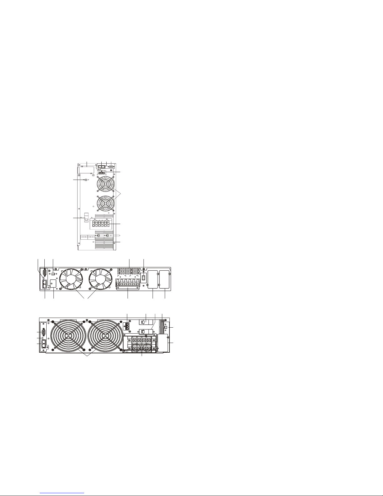
2.3.2 Rear Panel Explanation
5/6k PM
10K PM
CB 1
Utility Input
Breaker
L12N1G1L21N2 2G2
OUTPUT INPUT
ON
OFF
S1
Ext. Battery
ParallelWorkComm.
TNVCommunicationNetwork
BusNotIntended to
EPO
RS232
+
-
G
A
B
N
I
FDCG L E
P
RS232
Not In t end ed to
TNVCommunication
Network
EPO
-
G
+
SLOT
BATTERY
EXT.
INPUT
BREAKER
INPUT
BREAKER
UTILITY
BYPASS
TB1
TB2
ONOFF
S1
C
A
B
FL
G
I
J
D
N
P
5K/6K with batt
Model
RS232
Utility Input
Breaker
Slot
INPUT
L12-N1: UTILITY INPUT
G1 : INPUT EAR TH
OUTPUT
L12N1G1L21N22G2
GROUND
L21-N22: UPS OUTPUT
G2 : OUTPUT EARTH
GROUND
EPO
PAT. NO.:
US 6906501, TW 202668
Parallel Work Comm.
TNV Communication Network
Bus Not Intended to
Ext. Battery
+
-
G
A
CD
G
N
F
L
P
I
B
11
A RS232 Port
B Terminal Resistor for Parallel function
C CAN Bus Connection Port for Parallel System
D Customer Options Slot 1
E Customer Options Slot 2
F Cooling Fan
G External Battery Connector
I Utility Input Breaker CB1
L Input/Output Terminal Block
N EPO(Emergency Power Off): Short to enable the function
P Air Ventilation Hole
 Loading...