

Page 1

CMi4110
User’s Manual
English
Page 2

CMi4110 User’s Manual English v1.3
CMi4110 User’s Manual English v1.3
page | 2 (27)
[2018-06]
V1.3
Contents
1 DOCUMENT NOTES ..................................................................................................... 3
1.1 COPYRIGHT AND TRADEMARK ......................................................................................... 3
1.2 CONTACTS ..................................................................................................................... 3
2 IMPORTANT USAGE AND SAFETY INFORMATION ................................................... 4
3 USING THIS MANUAL .................................................................................................. 5
3.1 PURPOSE AND AUDIENCE ............................................................................................... 5
3.2 ONLINE RESOURCES ...................................................................................................... 5
3.3 SYMBOLS ....................................................................................................................... 5
4 INTRODUCTION ............................................................................................................ 6
4.1 PURPOSE ....................................................................................................................... 6
4.2 APPLICATION DESCRIPTION ............................................................................................. 6
4.3 PRODUCT FEATURES ...................................................................................................... 6
4.4 COMPATIBILITY ............................................................................................................... 7
5 GETTING STARTED ...................................................................................................... 8
5.1 PURPOSE ....................................................................................................................... 8
5.2 PRODUCT SPECIFICATION ............................................................................................... 8
5.3 MOUNT AND START-UP THE DEVICE ................................................................................. 8
5.3.1 Mounting and connection ............................................................................................ 8
5.3.2 Connection of antenna ................................................................................................ 8
5.3.3 Start-up and LED indications....................................................................................... 9
5.3.4 Switch off/reboot module ........................................................................................... 10
6 ADMINISTRATION REFERENCE ................................................................................ 11
6.1 PURPOSE ..................................................................................................................... 11
6.2 SECURITY AND ACCESS CONTROL ................................................................................. 11
6.3 CONFIGURATION OPTIONS ............................................................................................ 11
6.4 ADAPTIVE DATA RATE (ADR) ........................................................................................ 12
6.5 TRANSMIT INTERVAL ..................................................................................................... 12
6.5.1 EcoMode ................................................................................................................... 12
6.6 MESSAGE FORMATS ..................................................................................................... 13
6.6.1 Message structure ..................................................................................................... 13
6.6.2 Structure and payload ............................................................................................... 14
6.7 DOWNLINK ................................................................................................................... 21
7 TECHNICAL SPECIFICATIONS .................................................................................. 23
8 TYPE APPROVALS ..................................................................................................... 25
9 DOCUMENT HISTORY ................................................................................................ 26
9.1 VERSIONS .................................................................................................................... 26
10 REFERENCES ................................................................ ............................................. 27
10.1 TERMS AND ABBREVIATIONS ......................................................................................... 27
10.2 NUMBER REPRESENTATION .......................................................................................... 27
Page 3

CMi4110 User’s Manual English v1.3
CMi4110 User’s Manual English v1.3
page | 3 (27)
[2018-06]
V1.3
1 Document notes
All information in this manual, including product data, diagrams, charts, etc. represents information on
products at the time of publication, and is subject to change without prior notice due to product
improvements or other reasons. It is recommended that customers contact Elvaco AB for the latest
product information before purchasing a CMi Series product.
The documentation and product are provided on an “as is” basis only and may contain deficiencies or
inadequacies. Elvaco AB takes no responsibility for damages, liabilities or other losses by using this
product.
1.1 Copyright and trademark
© 2018, Elvaco AB. All rights reserved. No part of the contents of this manual may be transmitted or
reproduced in any form by any means without the written permission of Elvaco AB. Printed in Sweden.
CMi Series is a trademark of Elvaco AB, Sweden.
1.2 Contacts
Elvaco AB Headquarter
Kabelgatan 2T
434 37 Kungsbacka
SWEDEN
Phone: +46 300 30250
E-Mail: [email protected]
Elvaco AB Technical Support
Phone: +46 300 434300
E-Mail: [email protected]
Online: http://www.elvaco.com
Page 4

CMi4110 User’s Manual English v1.3
CMi4110 User’s Manual English v1.3
page | 4 (27)
[2018-06]
V1.3
2 Important usage and safety information
The following safety precautions must be observed during all phases of the operation, usage, service or
repair of any CMi Series product. Users of the product are advised to convey the information to users and
operating personnel and to incorporate these guidelines into all manuals supplied with the product.
Failure to comply with these precautions violates safety standards of design, manufacture and intended
use of the product. Elvaco AB assumes no liability for customer’s failure to comply with these
precautions.
CMi4110 receives and transmits radio frequency energy while switched on. Remember that interference
can occur if the product is used close to TV sets, radios, computers or inadequately shielded equipment.
Follow any special regulations and always switch off the product wherever forbidden, or when you
suspect that it may cause interference or danger.
Page 5
CMi4110 User’s Manual English v1.3
CMi4110 User’s Manual English v1.3
page | 5 (27)
[2018-06]
V1.3
3 Using this manual
3.1 Purpose and audience
This manual provides all information needed to mount, deploy and configure CMi4110 (Landis+Gyr
description: WZU-LoRa) and targets system integrators.
3.2 Online resources
To download the latest version of this user’s manual, or to find information in other languages, please
visit http://www.elvaco.com/.
3.3 Symbols
The following symbols are used throughout the manual to emphasize important information and useful
tips:
The Note symbol is used to mark information that is important to take into consideration for
safety reasons or to assure correct operation of the meter connectivity module.
The Tip symbol is used to mark information intended to help you get the most out of your
product. It can for example be used to highlight a possible customization option related to the
current section.
Table 1 provides information on how the product should be used.
Symbol
Description
Waste electrical products should not be disposed of with household waste. Please recycle
where facilities exist. Contact your Local Authority for recycling advise.
Electrostatic-sensitive device. Please observe the necessary ESD protective measures when
installing the module.
Table 1: Usage information
Page 6
CMi4110 User’s Manual English v1.3
CMi4110 User’s Manual English v1.3
page | 6 (27)
[2018-06]
V1.3
4 Introduction
4.1 Purpose
This chapter provides a general description of CMi4110. In the next-coming sections you will learn more
about possible applications for the product and how CMi4110 can be combined with other products to
build versatile solutions.
4.2 Application description
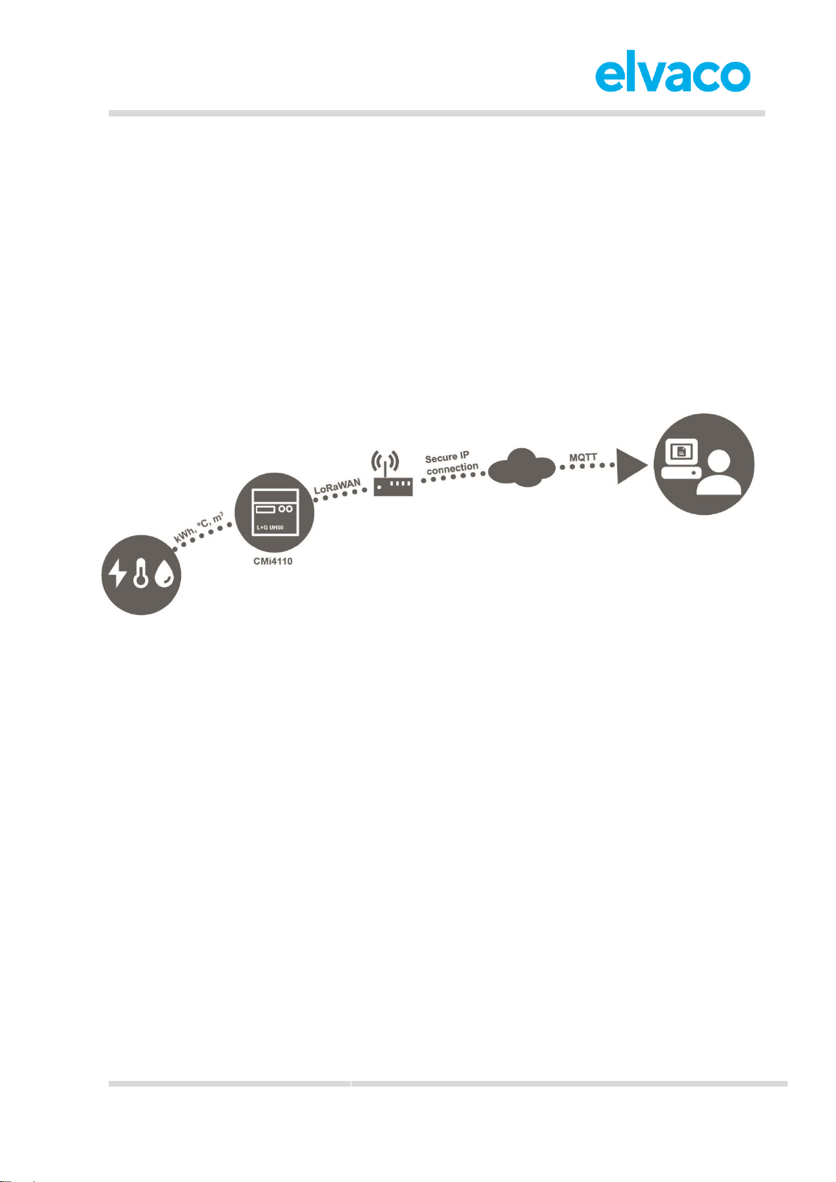
CMi4110 is a cost-effective LoRaWAN meter connectivity module, which is mounted in a Landis+Gyr
UH50 meter or a UC50 calculator. It uses a very energy-efficient scheme to deliver meter data to a
receiving (application) server over a LoRaWAN network. Meter data is securely transmitted, using
LoRaWAN end-to-end security scheme.
CMi4110 can both be retrofitted into deployed meters or mounted before deployment.
4.3 Product features
CMi4110 has the capability to offer a combination of battery operation with very long lifetime and a
versatile application through its many configuration options. Key features of the module include:
• Long battery lifetime
The module’s EcoMode feature enables the module to achieve a battery-lifetime of at least 11+1
years.
• No meter installation needed
As soon as the meter connectivity module has been mounted and started up, it will join the
LoRaWAN network and start delivering meter data, i.e. no manual steps need to be taken in
order to install the product in the meter.
• Quick commissioning
The product uses Elvaco’s One-Touch Commissioning (OTC) solution to securely and quickly
configure products deployed. Using Elvaco’s OTC App, simply enter your desired settings and
place your phone on the right side of the L+G UH50 meter / UC50 calculator. New settings will be
applied instantaneously via NFC.
• A unique and flexible message scheme
• Meter data aligned with meter’s internal clock and redundant daily energy values enables
coordinated high-precision readouts without network congestion and assures reliable
delivery of daily energy consumption.
• Several message formats to choose between, including JSON, gives the right fit for the
unique demands of each application.
Page 7

CMi4110 User’s Manual English v1.3
CMi4110 User’s Manual English v1.3
page | 7 (27)
[2018-06]
V1.3
4.4 Compatibility
CMi4110 is compatible with all L+G UH50 meters using software version 5.15 or higher as well as with all
L+G UC50 calculators using software version 8.06 or higher.
CMi4110 is supplied with power from the UH50/UC50 D cell battery. The module is also compatible with
Elvaco’s 230V CMip2110 PSUs and with the following PSUs from Landis+Gyr: WZU-AC230, WZUAC110, WZU-ACDC24-00.
Page 8
CMi4110 User’s Manual English v1.3
CMi4110 User’s Manual English v1.3
page | 8 (27)
[2018-06]
V1.3
5 Getting started
5.1 Purpose
This chapter provides instructions on how to get started with the CMi4110. After reading and carefully
following each step of this chapter, your meter connectivity module will be mounted, connected and
started up.
5.2 Product specification
5.3 Mount and start-up the device
5.3.1 Mounting and connection
CMi4110 is mounted in module slot 2 of a L+G UH50 heat meter or a L+G UC50 heat calculator.
5.3.2 Connection of antenna
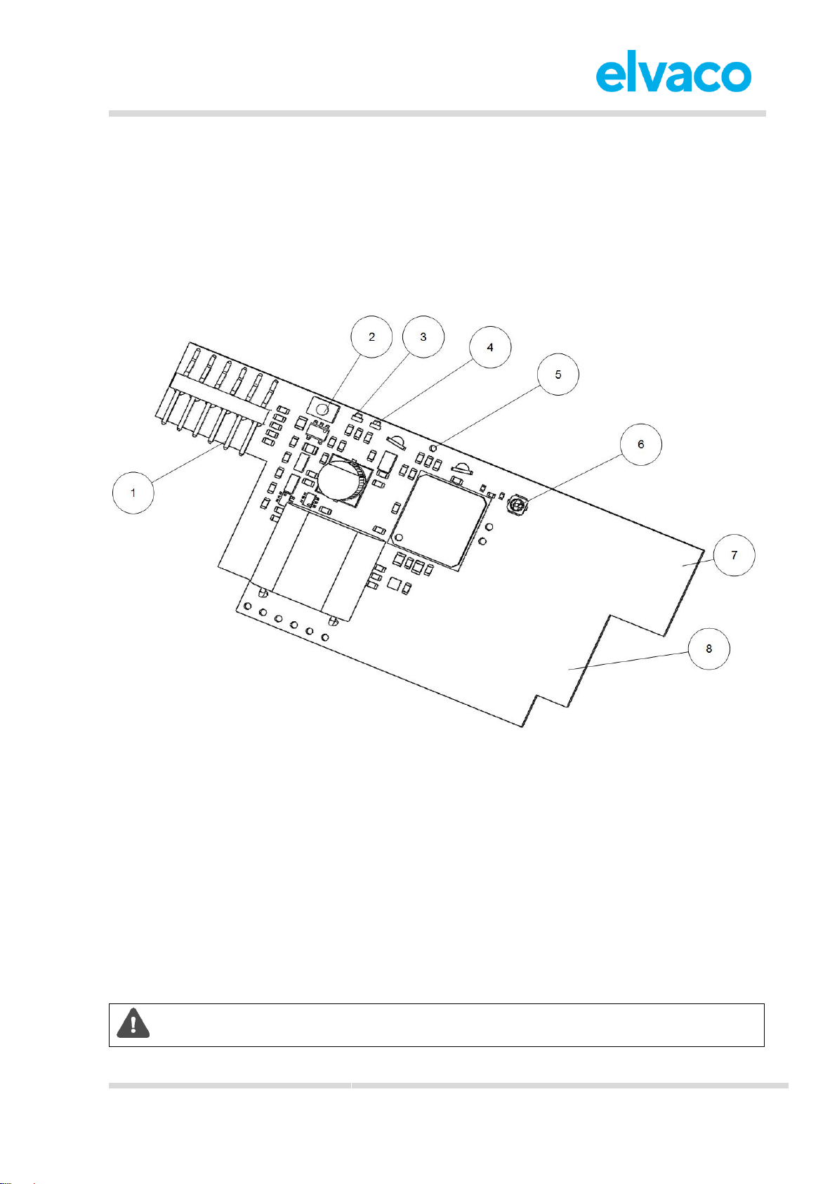
If using CMi4110Ext, the SMA connector (6) is used to connect an external antenna. Please order your
desired antenna (wall-mount or magnet-mount) from the Elvaco (or L+G) accessory assortment.
Make sure to mount the antenna at least 0.5 meters away from the meter in order not to
disturb the meter and attached cables.
1. Meter interface
2. Push button
3. Green LED
4. Red LED
5. Tamper switch (optional)
6. External antenna connector (optional)
7. LoRa antenna
8. NFC antenna
Page 9
CMi4110 User’s Manual English v1.3
CMi4110 User’s Manual English v1.3
page | 9 (27)
[2018-06]
V1.3
5.3.3 Start-up and LED indications
Module activation
Upon delivery, CMi4110 is set to passive mode, which means no messages will be transmitted from the
module. There are two ways to activate the module:
1. Press down the push button (2) for at least 5 seconds until the green LED lights up, then release
the button. A few seconds (1 to 11 seconds) later, CMi4110 will indicate start-up by flashing red
and green LEDs for one second.
2. Via the Elvaco OTC app. Go to Apply mode, set the Module power to “active” and click Apply
settings. Place the phone on the right side of the meter. The mobile phone should vibrate three
times. This indicates that settings have successfully been applied.
Network join
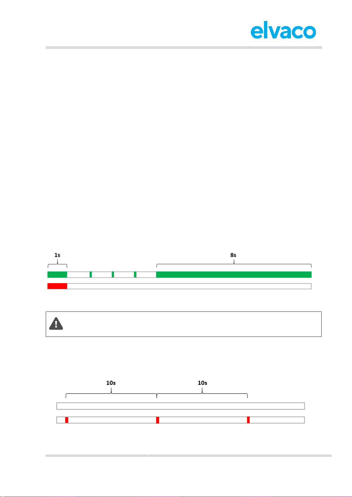
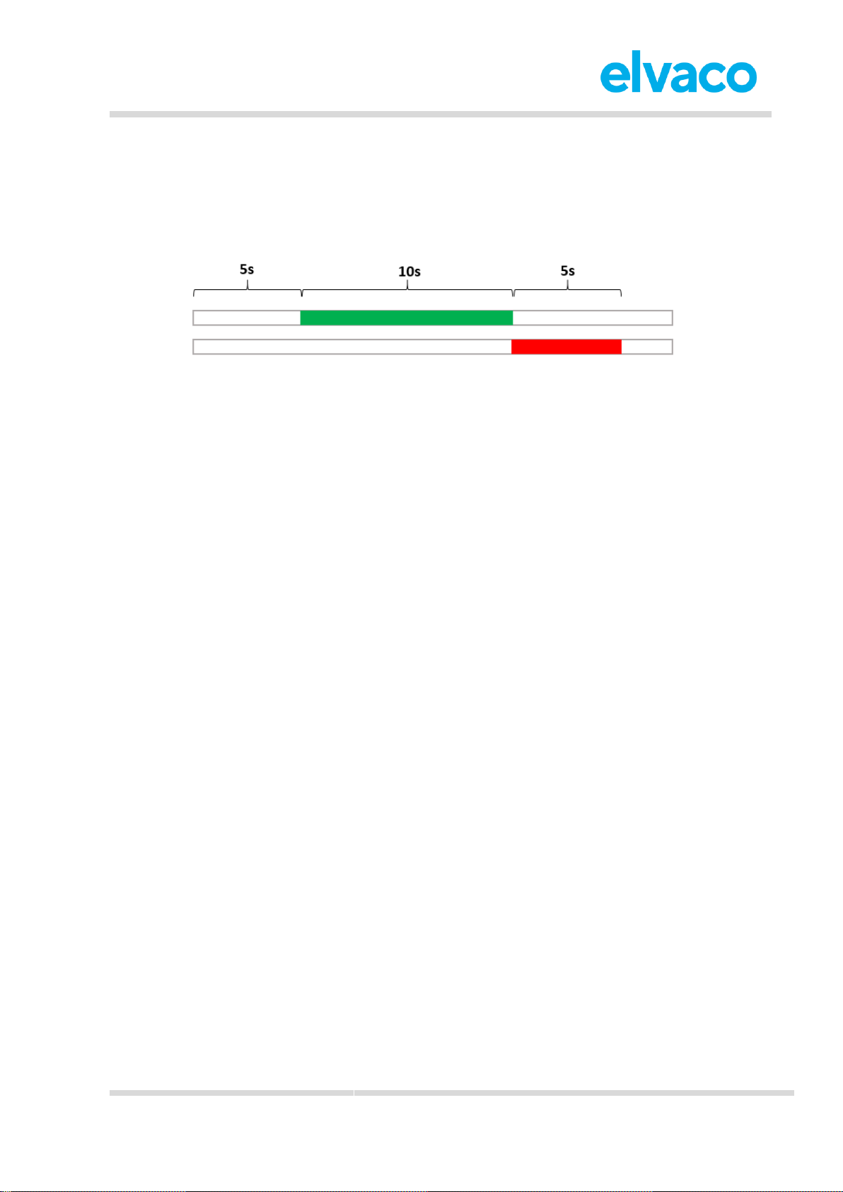
After activation, CMi4110 will attempt to join the LoRaWAN network. The phase is indicated by short
flashes every 5th second on the green LED. When CMi4110 succeeds in joining the LoRaWAN network,
the green LED will lighten up for 8 seconds, as illustrated by Figure 1.
If the module fails to join the LoRaWAN network 6 times, it will wait for 60 minutes before another join
attempt is initiated in order to conserve battery. A new join attempt cycle can be manually started anytime
by pressing down the push button (2) for at least 5 seconds, until the green LED lights up, and then
release the button.
When the module has joined the LoRaWAN network, meter data will initially be transmitted from the
module every minute (regardless of transmit interval settings) in order to set the right data rate. After 10
minutes of calibration, the module will start to deliver meter data using its configured settings.
Figure 1: Network join LED indication
When activation-by-personalization (ABP) is used, the module does not perform a join
operation before sending messages. Therefore, the 8-second indication of connection will
not appear in ABP mode.
Soft start
In rare cases, if the battery is weak, the module will perform a soft start to be able to start-up despite the
condition of the battery. The soft start takes 10 minutes to complete. The red LED will blink shortly every
10th second until the start-up has completed.
Figure 2: Soft start LED indication
Page 10
CMi4110 User’s Manual English v1.3
CMi4110 User’s Manual English v1.3
page | 10 (27)
[2018-06]
V1.3
5.3.4 Switch off/reboot module
To reboot the module, press and hold the push button (2) for 5-15 seconds. Release the button when the
green LED is lit.
To switch off the module, press and hold the push button (2) for 15-20 seconds. Release the button when
the red LED is lit.
Figure 3: Reboot/switch off module
Page 11
CMi4110 User’s Manual English v1.3
CMi4110 User’s Manual English v1.3
page | 11 (27)
[2018-06]
V1.3
6 Administration reference
6.1 Purpose
This chapter contains detailed information about configuring options for CMi4110 and format of the
different message types transmitted from the module.
6.2 Security and access control
CMi4110 has a configuration lock feature, which prevents unauthorized access to the module. When
configuration lock has been enabled, a Product Access Key will be needed to access the device. For
more information about security and access control for CMi4110, please refer to the One-touch
commissioning (OTC) documentation, available on the Elvaco website.
6.3 Configuration options
CMi4110 is configured via the Elvaco OTC app. It uses NFC to transfer settings to the module.
Downlink may also be used to for some applications, see section 6.7 Downlink for more information.
Please note that the Elvaco OTC app is only compatible with Android phones with Android
5.0 or later.
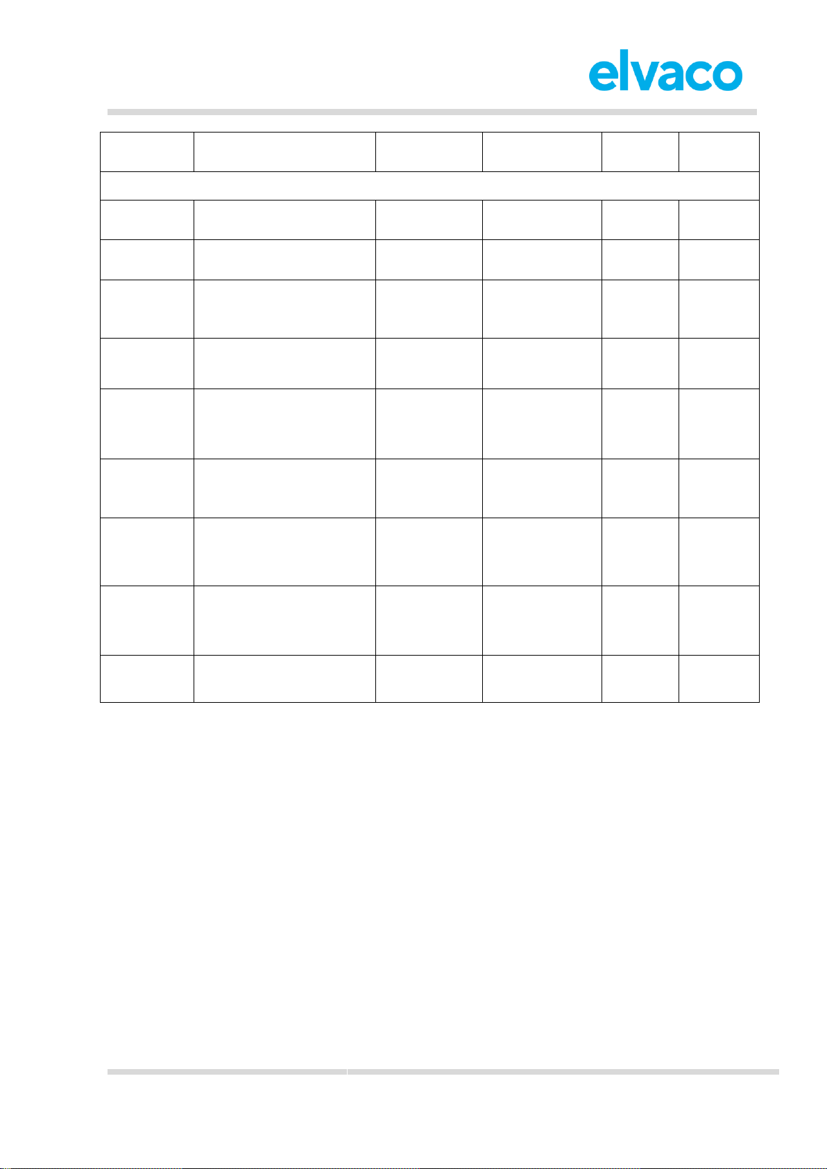
Table 2 provides a summary of all settings.
Field name
(Abbr.)
Description
Default value
Device access
Locked device &
correct Product
Access Key
or
Open device
Device
access
No
Product
Access
Key
Downlink
Meter ID
Meter identification number of
the meter. Not configurable.
N/A
Readable
Readable
N/A
Power mode
Used to activate/deactivate
the module.
Passive
Readable /
Writeable
Readable
N/A
Message
format
The message format
determines the structure and
payload of the telegram sent
from the module.
0
(Compact)
Readable /
Writeable
Readable
N/A
EcoMode
When activated, 11+1 years
of battery-life is guaranteed
by adapting the transmit
interval of the module to
current signal conditions.
On
Readable /
Writeable
Readable
Writeable
Maximum
daily
transmissions
Maximum number of
transmissions allowed per
day.
Inactive
Readable /
Writeable
Readable
Writeable
Date & Time
Date and time set for the
meter.
Current
date/time
Readable /
Writeable
Readable
Writeable
Set Time
Relative
Adjusts the time of the meter
relative to the current time.
N/A
Writeable
N/A
Writeable
Page 12
CMi4110 User’s Manual English v1.3
CMi4110 User’s Manual English v1.3
page | 12 (27)
[2018-06]
V1.3
Configuration
Lock
Locks the module to prevent
unauthorized access.
Open
Readable /
Writeable
Readable
Writeable
LoRaWAN settings
Device EUI
Unique module identification
number. Not configurable.
Device-unique
64-bit number
Readable
Readable
N/A
Activation
type
Sets the way the device joins
the LoRaWAN network.
OTAA
Readable /
Writeable
Readable
N/A
Network join
Used to display whether the
module has joined the
LoRaWAN network.
N/A
Readable
Readable
N/A
Join EUI
Application ID that
determines where data ends
up.
0x 00 00 00 00 00
00 00 00
Readable /
Writeable
Readable
N/A
Application
key
Encryption key for payload
data (only applicable in OTAA
mode).
Device-unique
128-bit number
Writeable
N/A
N/A
Application
session key
Encryption key for payload
data (only applicable in ABP
mode).
Device-unique
128-bit number
Writeable
N/A
N/A
Device
address
Unique address used by the
device to identify itself on the
LoRaWAN network (only
applicable in ABP mode).
Device-unique
32-bit number
Writeable
N/A
N/A
Network
session key
Encryption key for payload
data (only applicable in ABP
mode).
Device-unique
128-bit number
Writeable
N/A
N/A
Current data
rate
The current data rate used for
the module.
N/A
Readable
Readable
N/A
Table 2: Configuration options
6.4 Adaptive data rate (ADR)
ADR is part of the LoRaWAN standard where the network server determines the optimal rate of
communication for the module based on current signal conditions. In best case, the module will use its
highest data rate (DR5) in order to be as energy-efficient as possible. When signal conditions are poor,
the network server will incrementally lower the data rate until it is able to receive the message. When the
data rate is low, the energy consumption per telegram will increase.
6.5 Transmit interval
6.5.1 EcoMode
When EcoMode is active, a battery-lifetime of at least 11+1 years is guaranteed for the module. The
module is able to achieve this by adapting its transmit interval to current signal conditions on the
LoRaWAN network. In other words, when signal conditions are poor (and data rate is low), the module
will send data less frequently in order to conserve battery-life. When signal conditions are decent, the
module will be able to send data more frequently.
Page 13
CMi4110 User’s Manual English v1.3
CMi4110 User’s Manual English v1.3
page | 13 (27)
[2018-06]
V1.3
Table 3 summarizes the transmit interval for different data rates.
Data rate
Transmit interval
DR0
60 minutes
DR1 - DR2
30 minutes
DR3 - DR5
15 minutes
Table 3: Data rate and transmit interval
Set the transmit interval manually
If the transmit interval needs to be set to a fixed value, EcoMode can be disabled. Use the Elvaco OTC
App to configure the transmit interval.
If EcoMode has been disabled, guarantees about battery-life no longer apply, even if
EcoMode is activated later on.
Set an upper limit for number of daily telegrams
In some cases, it might be necessary to limit the number of daily telegrams that the module should be
allowed to send. By using the MaxDTx parameter, such a limit can be easily set. For example, by setting
MaxDTx to “24”, no more than 24 telegrams will be transmitted each day (regardless of the data rate).
Table 4 provides a set of examples.
MaxDTx value
Maximum transmit interval
1
Once per day
24
Once per hour
48
Once per 30 minutes
96
Once per 15 minutes
Table 4: MaxDTx setting
To achieve a battery life time of 16+1 (storage) years, the MaxDTx parameter needs to be
set to 9 or lower.
6.6 Message formats
CMi4110 has five different message formats: Standard, Compact, JSON, Scheduled-daily redundant and
Scheduled-extended. Each message type will be described in detail in this section. All data messages
from the module will be transmitted on LoRa port 2.
6.6.1 Message structure
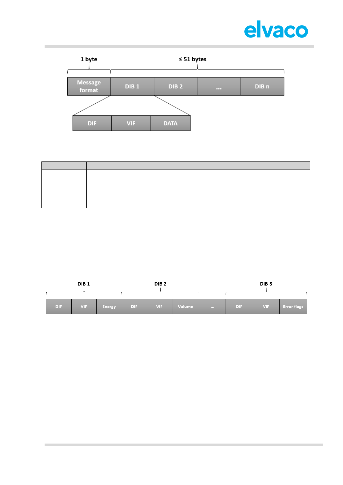
All message formats except for JSON are encoded according to M-Bus standard. Each telegram begins
with one byte specifying the message format. Then follows a sequence of data information blocks (DIBs).
The data and structure of the DIBs depends on the message type set. Each DIB contains a data
information field (DIF), a value information field (VIF) and a data field (DATA), where the actual payload is
stored. The structure is illustrated by Figure 4.
Page 14
CMi4110 User’s Manual English v1.3
CMi4110 User’s Manual English v1.3
page | 14 (27)
[2018-06]
V1.3
Figure 4: CMi4110 M-Bus message structure
For message type JSON, the data is presented as plain text.
Field
Size
Description
Message type
1 byte
0 = Standard
1 = Compact
2 = JSON
3 = Scheduled – daily redundant
4 = Scheduled - extended
Table 5: Message type field
6.6.2 Structure and payload
In this section, a detailed description of each message format is provided.
6.6.2.1 Standard
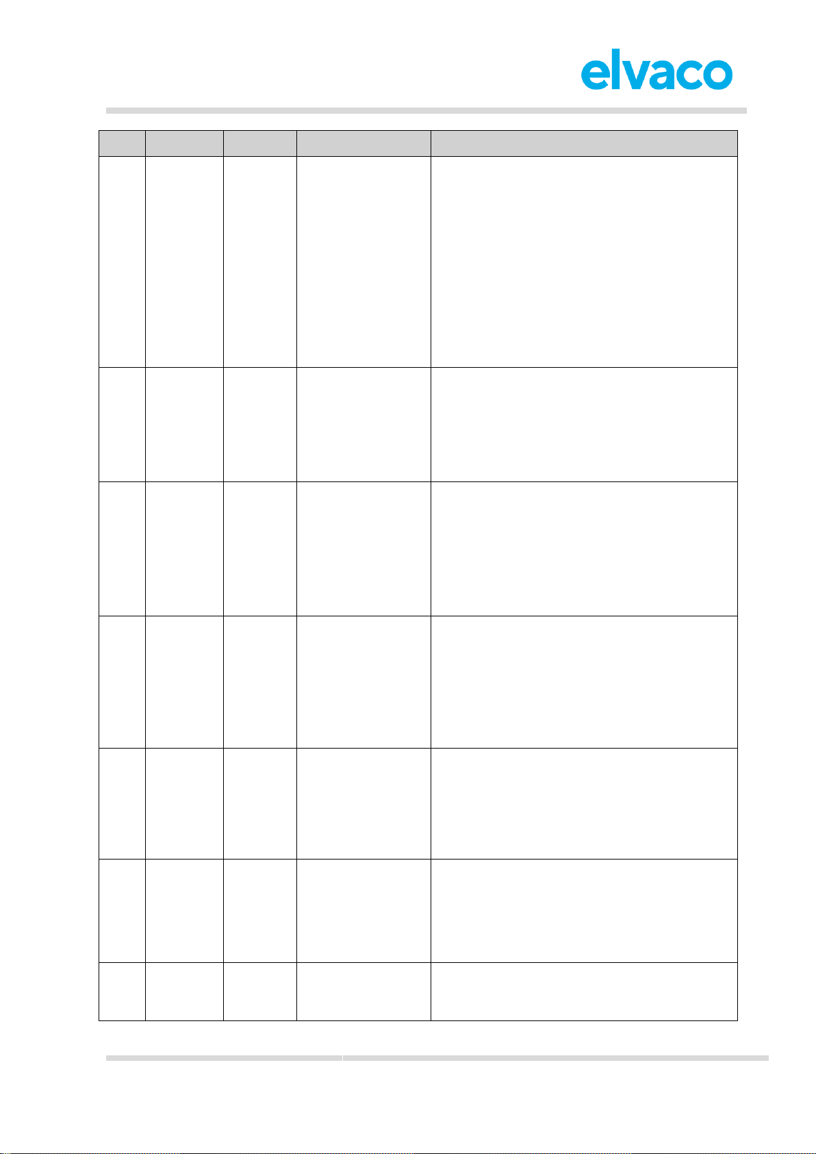
Figure 5 illustrates the structure of the message type for message format Standard. For a detailed
description of the data included in each field, see Table 6.
Figure 5: Structure, message format Standard
Page 15
CMi4110 User’s Manual English v1.3
CMi4110 User’s Manual English v1.3
page | 15 (27)
[2018-06]
V1.3
DIB
Field
Size
Data type
Description
1
Energy
6 bytes
(including
DIF/VIF)
BCD8
M-Bus Type A
Energy consumption (MWh, kWh, MJ, GJ)
Mapped to OBIS 6.8
0C06xxxxxxxx = MWh, 3 decimals = kWh
0C07xxxxxxxx = MWh, 2 decimals
0CFB00xxxxxxxx = MWh, 1 decimal
0CFB01xxxxxxxx = MWh, 0 decimals
0C06xxxxxxxx = kWh
0C0Exxxxxxxx = GJ, 3 decimals
0C0Fxxxxxxxx = GJ, 2 decimals
0CFB08xxxxxxxx = GJ, 1 decimal
0CFB09xxxxxxxx = GJ, 0 decimals
2
Volume
6 bytes
(including
DIF/VIF)
BCD8
M-Bus Type A
Volume (m3)
Mapped to OBIS 6.26
0C14xxxxxxxx = m3, 2 decimals
0C15xxxxxxxx = m3, 1 decimal
0C16xxxxxxxx = m3, 0 decimals
3
Power
5 bytes
(including
DIF/VIF)
BCD8
M-Bus Type A
Power (kW)
Mapped to OBIS 6.4
0B2Bxxxxxx = kW, 3 decimals
0B2Cxxxxxx = kW, 2 decimals
0B2Dxxxxxx = kW, 1 decimal
0B2Exxxxxx = kW, 0 decimals
4
Flow
5 bytes
(including
DIF/VIF)
BCD6
M-Bus Type A
Flow (m3/h)
Mapped to OBIS 6.27
0B3Bxxxxxx = m3/h, 3 decimals
0B3Cxxxxxx = m3/h, 2 decimals
0B3Dxxxxxx = m3/h, 1 decimal
0B3Exxxxxx = m3/h, 0 decimals
5
Fw temp
4 bytes
(including
DIF/VIF)
BCD4
Forward temperature (°C)
Mapped to OBIS 6.29
0A5Axxxx = °C, 1 decimal
0A5Bxxxx = °C, 0 decimals
6
Rt temp
4 bytes
(including
DIF/VIF)
BCD4
Return temperature (°C)
Mapped to OBIS 6.28
0A5Exxxx = °C, 1 decimal
0A5Fxxxx = °C, 0 decimals
7
Meter ID
6 bytes
(including
DIF/VIF)
According to MBus EN13757-3
identification field
Meter ID
0C78xxxxxxxx
Page 16
CMi4110 User’s Manual English v1.3
CMi4110 User’s Manual English v1.3
page | 16 (27)
[2018-06]
V1.3
8
Error flags
5 bytes
(including
DIF/VIF)
Uint16
M-Bus Type C
Error and warning flags
02FD17xxxx
Table 6: DIB fields, message type standard
6.6.2.2 Compact
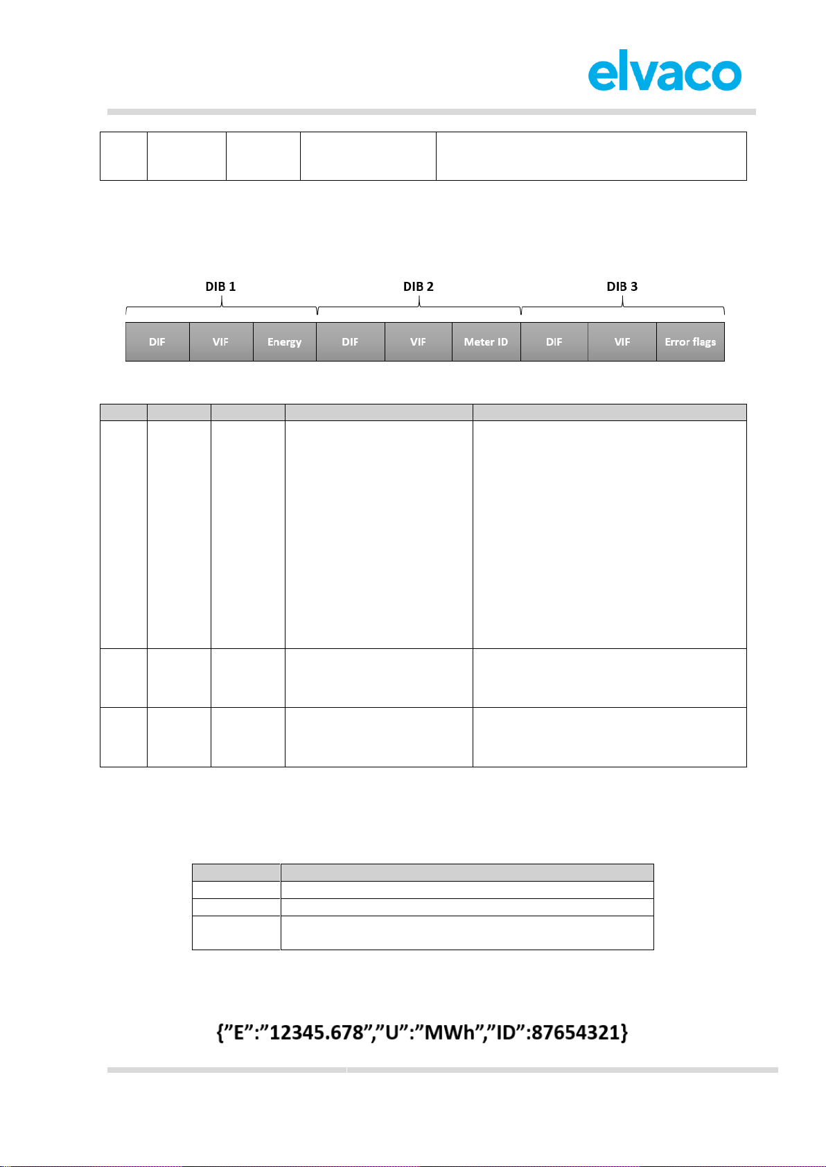
Figure 6 illustrates the structure for message format Compact. For a detailed description of the data
included in each field, see Table 7.
Figure 6: DIB structure, message type compact
DIB
Field
Size
Data type
Description
1
Energy
6 bytes
(including
DIF/VIF)
BCD8
M-Bus Type A
Energy consumption (MWh, kWh, MJ,
GJ)
Mapped to OBIS 6.8
0C06xxxxxxxx = MWh, 3 decimals =kWh
0C07xxxxxxxx = MWh, 2 decimals
0CFB00xxxxxxxx = MWh, 1 decimal
0CFB01xxxxxxxx = MWh, 0 decimals
0C06xxxxxxxx = kWh
0C0Exxxxxxxx = GJ, 3 decimals
0C0Fxxxxxxxx = GJ, 2 decimals
0CFB08xxxxxxxx = GJ, 1 decimal
0CFB09xxxxxxxx = GJ, 0 decimals
2
Meter
ID
6 bytes
(including
DIF/VIF)
According to M-Bus
EN13757-3 identification
field
Meter ID
0C78xxxxxxxx
3
Error
flags
5 bytes
(including
DIF/VIF)
Uint16
M-Bus Type C
Error and warning flags
02FD17xxxx =Error and warning flags
Table 7: DIB fields, message type compact
JSON
For message format JSON, the data is presented in a plain text format. Table 8 provides a description of
all fields included in the telegram.
Field
Description
Energy
Energy consumption
Unit
Unit of energy consumption
Meter ID
Identification number of the meter in which the module is
mounted.
Table 8: Fields, message type JSON
In Figure 7 an example of a message type JSON telegram is presented.
Figure 7: JSON message example
Page 17
CMi4110 User’s Manual English v1.3
CMi4110 User’s Manual English v1.3
page | 17 (27)
[2018-06]
V1.3
6.6.2.4 Scheduled mode
When using message format Scheduled, two types of messages will be transmitted from the module: a
clock message and a data message. The difference between the two is described in Table 9. There are
two types of scheduled mode message types: daily redundant and extended.
Message
Time interval
Description
Clock
message
Once per day
The clock message presents the current time of
UH50/UC50. It can be used to verify that the clock
is correct and has not drifted more than accepted.
Byte 0 = 0xFA
Byte 1 = DIF, 0x04 = valid, 0x34 =invalid
Byte 2 = VIF, 0x6D
Byte 3-6 = 32-bit date/time encoded as M-Bus
format F
Data message
Determined by MaxDTx
parameter.
The data message contains the fields listed in
Table 11.
Table 9: Clock message and data message
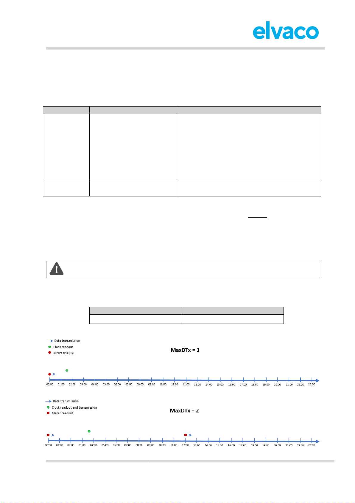
The clock message will be transmitted once every day and the data message at least (regulated by
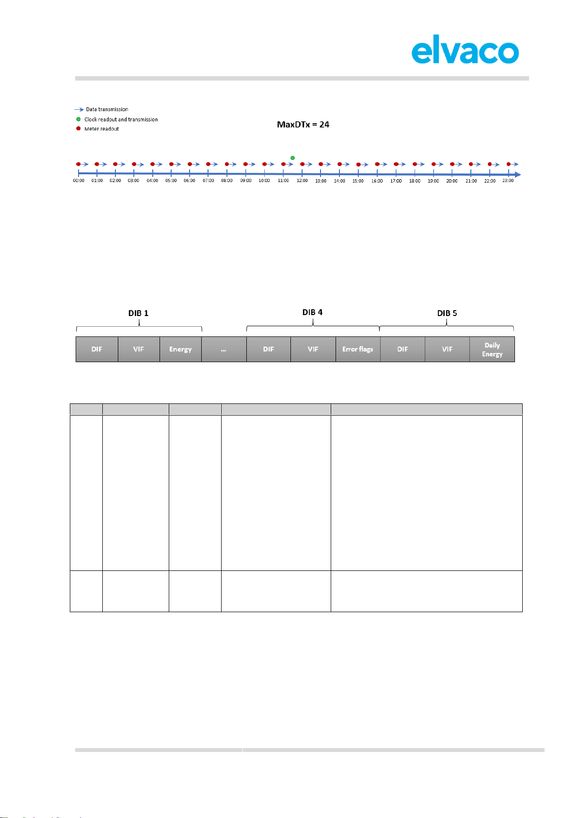
MaxDTx parameter) once every day (on LoRa port 3). Figure 8 illustrates the principle. Note that although
the meter readout will occur on top-of-the-hour, the data message will not necessarily be transmitted at
that exact time. The LoRa transmission will occur after a random delay of 1-30 minutes. The meter
readout for the clock message occurs at a random hour (00:00-23:00) at a random minute in the 35-45
interval. The clock message will be transmitted immediately after readout.
When using message type Scheduled, the MaxDTx cannot not be set higher than 24.
The transmit interval of the data message is adapted to current data rate and MaxDTx settings. Note that
for message type Scheduled, the MaxDTx parameter can only assume the values listed in Table 10.
Parameter
Values
MaxDTx
1, 2, 3, 4, 6, 8, 12, 24
Table 10: MaxDTx values for message type scheduled
Page 18
CMi4110 User’s Manual English v1.3
CMi4110 User’s Manual English v1.3
page | 18 (27)
[2018-06]
V1.3
Scheduled- daily redundant
The data message of message format Scheduled mode-daily redundant contains an accumulated daily
energy field, which is updated at 24:00 each day. Depending on MaxDTx settings and data rate, the field
will be included in between 1-24 data messages per day. This will increase the probability of the value
being received. For example, if MaxDTx is set to “12”, the accumulated energy read at 24:00 will be
transmitted 12 times during the 24 next coming hours.
Figure 9: DIB structure, message type scheduled – daily redundant
DIB
Field
Size
Data type
Description
1
Energy
6 bytes
(including
DIF/VIF)
BCD8
M-Bus Type A
Energy consumption (MWh, kWh, MJ,
GJ)
Mapped to OBIS 6.8
0C06xxxxxxxx = MWh, 3 decimals = kWh
0C07xxxxxxxx = MWh, 2 decimals
0CFB00xxxxxxxx = MWh, 1 decimal
0CFB01xxxxxxxx = MWh, 0 decimals
0C0Exxxxxxxx = GJ, 3 decimals
0C0Fxxxxxxxx = GJ, 2 decimals
0CFB08xxxxxxxx = GJ, 1 decimal
0CFB09xxxxxxxx = GJ, 0 decimals
2
Meter ID
6 bytes
(including
DIF/VIF)
According to M-Bus
EN13757-3
identification field
Meter ID
0C78xxxxxxxx
Figure 8: Data messages and MaxDTx settings
Page 19
CMi4110 User’s Manual English v1.3
CMi4110 User’s Manual English v1.3
page | 19 (27)
[2018-06]
V1.3
3
Meter
date/time
6 bytes
(including
DIF/VIF)
M-Bus Type F
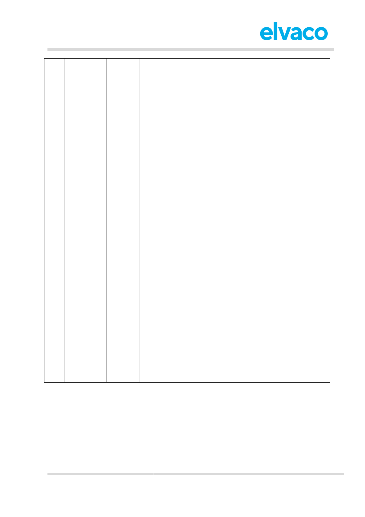
Meter date and time (YY-MM-DD HH:MM)
Mapped to OBIS 9.36
046Dxxxxxxxx
Bit 31-28 = Year-high*
Bit 27-24 = Month
Bit 23-21 = Year-low*
Bit 20-16 = Day
Bit 15 = Summer time flag**
Bit 14-13 = Century
Bit 12-8 = Hour
Bit 7 = Error flag
Bit 6 = Reserved for future use***
Bit 5-0 = Minute
*The year is read by combining the yearhigh and year-low field. For example,
year-high = 0010 and year-low = 010 =>
year = 0010010
**0 = standard time, 1= daylight-saving
time
***0 = timestamp is valid, 1 = timestamp
is not valid
4
Accumulated
energy at
24:00
6
Bytes
(including
DIF/VIF)
BCD8
M-Bus Type A
Energy consumption (MWh, kWh, MJ,
GJ)
Mapped to OBIS 6.8
4C06xxxxxxxx = MWh, 3 decimals = kWh
4C07xxxxxxxx = MWh, 2 decimals
4CFB00xxxxxxxx = MWh, 1 decimal
4CFB01xxxxxxxx = MWh, 0 decimals
4C0Exxxxxxxx = GJ, 3 decimals
4C0Fxxxxxxxx = GJ, 2 decimals
4CFB08xxxxxxxx = GJ, 1 decimal
4CFB09xxxxxxxx = GJ, 0 decimals
4
Error flags
5 bytes
(including
DIF/VIF)
Uint16
M-Bus Type C
Error and warning flags
02FD17xxxx =Error and warning flags
Table 11: DIB fields, message type scheduled – daily redundant
Scheduled-extended
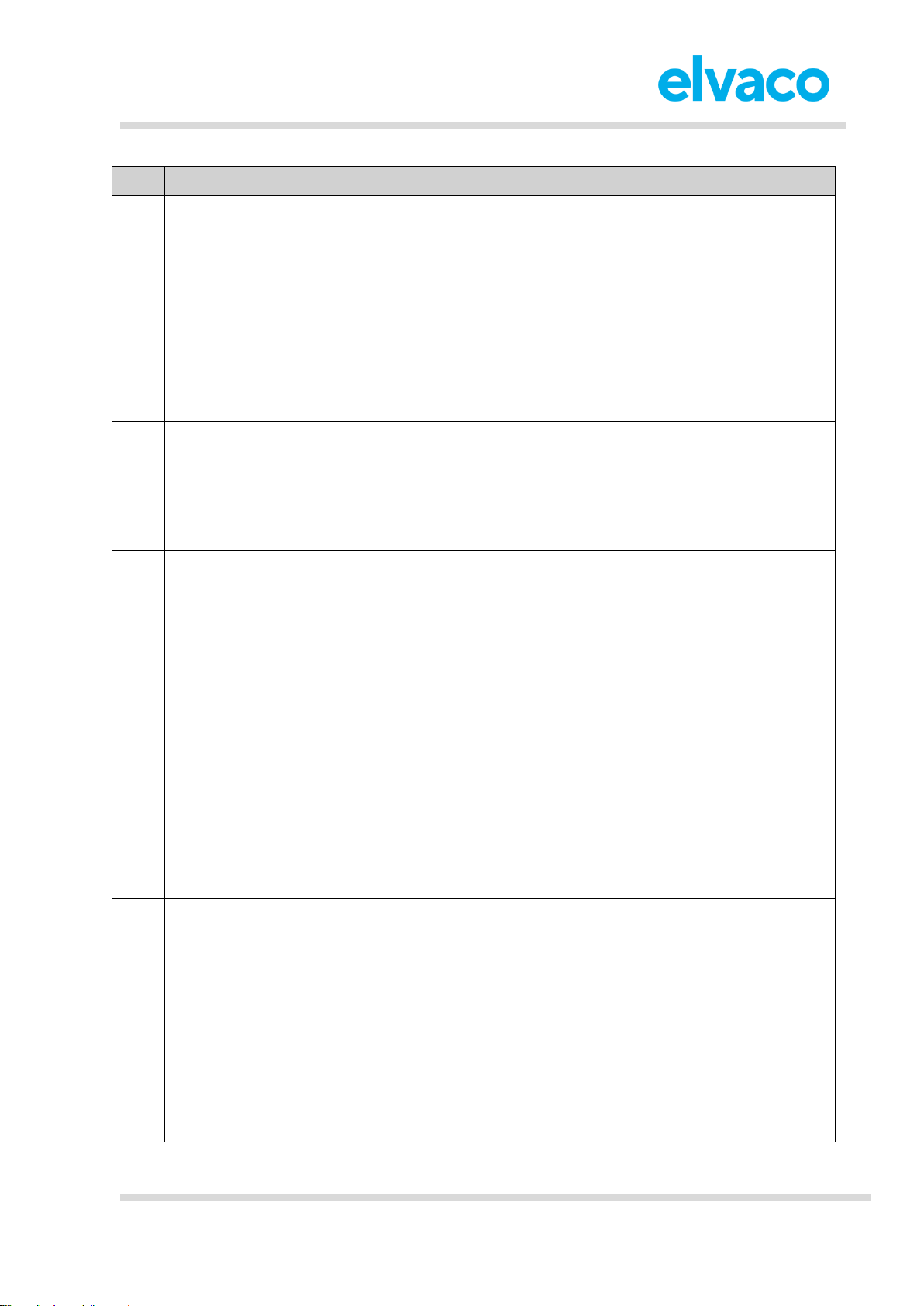
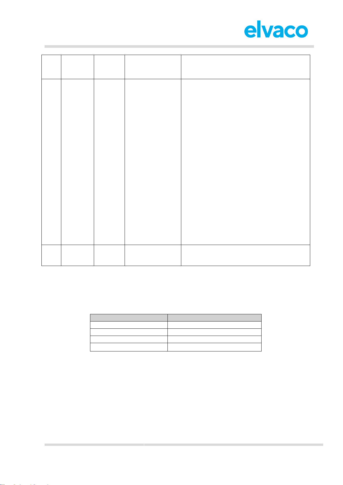
The data message of message format Scheduled mode-extended contains all the meter data included in
the Standard telegram. In addition to these, a timestamp from the meter (meter date/time) is included in
each telegram.
Page 20
CMi4110 User’s Manual English v1.3
CMi4110 User’s Manual English v1.3
page | 20 (27)
[2018-06]
V1.3
DIB
Field
Size
Data type
Description
1
Energy
6 bytes
(including
DIF/VIF)
BCD8
M-Bus Type A
Energy consumption (MWh, kWh, MJ, GJ)
Mapped to OBIS 6.8
0C06xxxxxxxx = MWh, 3 decimals = kWh
0C07xxxxxxxx = MWh, 2 decimals
0CFB00xxxxxxxx = MWh, 1 decimal
0CFB01xxxxxxxx = MWh, 0 decimals
0C0Exxxxxxxx = GJ, 3 decimals
0C0Fxxxxxxxx = GJ, 2 decimals
0CFB08xxxxxxxx = GJ, 1 decimal
0CFB09xxxxxxxx = GJ, 0 decimals
2
Volume
6 bytes
(including
DIF/VIF)
BCD8
M-Bus Type A
Volume (m3)
Mapped to OBIS 6.26
0C14xxxxxxxx = m3, 2 decimals
0C15xxxxxxxx = m3, 1 decimal
0C16xxxxxxxx = m3, 0 decimals
3
Power
5 bytes
(including
DIF/VIF)
BCD8
M-Bus Type A
Power (kW)
Mapped to OBIS 6.4
0B2Bxxxxxx = kW, 3 decimals
0B2Cxxxxxx = kW, 2 decimals
0B2Dxxxxxx = kW, 1 decimal
0B2Exxxxxx = kW, 0 decimals
If first byte is set to “3B” instead of “0B”, this
indicates (value during error state)
4
Flow
5 bytes
(including
DIF/VIF)
BCD6
M-Bus Type A
Flow (m3/h)
Mapped to OBIS 6.27
0B3Bxxxxxx = m3/h, 3 decimals
0B3Cxxxxxx = m3/h, 2 decimals
0B3Dxxxxxx = m3/h, 1 decimal
0B3Exxxxxx = m3/h, 0 decimals
5
Fw temp
4 bytes
(including
DIF/VIF)
BCD4
Forward temperature (°C)
Mapped to OBIS 6.29
0A5Axxxx = °C, 1 decimal
0A5Bxxxx = °C, 0 decimals
6
Rt temp
4 bytes
(including
DIF/VIF)
BCD4
Return temperature (°C)
Mapped to OBIS 6.28
0A5Exxxx = °C, 1 decimal
0A5Fxxxx = °C, 0 decimals
Page 21
CMi4110 User’s Manual English v1.3
CMi4110 User’s Manual English v1.3
page | 21 (27)
[2018-06]
V1.3
7
Meter ID
6 bytes
(including
DIF/VIF)
According to MBus EN13757-3
identification field
Meter ID
0C78xxxxxxxx = Meter ID
8
Meter
date/time
6 bytes
(including
DIF/VIF
M-Bus Type F
Meter date and time (YY-MM-DD HH:MM)
Mapped to OBIS 9.36
046Dxxxxxxxx
Bit 31-28 = Year-high*
Bit 27-24 = Month
Bit 23-21 = Year-low*
Bit 20-16 = Day
Bit 15 = Summer time flag**
Bit 14-13 = Century
Bit 12-8 = Hour
Bit 7 = Error flag
Bit 6 = Reserved for future use***
Bit 5-0 = Minute
*The year is read by combining the year-high
and year-low field. For example, year-high =
0010 and year-low = 010 => year = 0010010
**0 = standard time, 1= daylight-saving time
***0 = timestamp is valid, 1 = timestamp is not
valid
9
Error flags
5 bytes
(including
DIF/VIF)
Uint16
M-Bus Type C
Error and warning flags
02FD17xxxx
Meter communication error message
When CMi4110 is unable to communicate with UH50/UC50, an error message will be transmitted on the
LoRaWAN network. Table 12 describes that error message for each message type.
Message type
Error message
Standard
0E00
Compact
0E00
JSON
{ }
Scheduled-daily redundant
0E00
Table 12: Meter communication error message
6.7 Downlink
CMi4110 supports configuration via downlink, i.e. sending commands to an end-device via the LoRaWAN
network. Note that this feature should only be used sparingly due to bandwidth consideration.
Communication via downlink can only be made in a short window after an uplink transmission from
module to server. Therefore, time-critical communication should not be performed over downlink.
Some appropriate use of downlink commands is:
• Adjusting the meter clock when message type scheduled is used.
• Adjusting the MaxDTx parameter in order to optimize the performance of CMi4110 on the
Page 22
CMi4110 User’s Manual English v1.3
CMi4110 User’s Manual English v1.3
page | 22 (27)
[2018-06]
V1.3
LoRaWAN network.
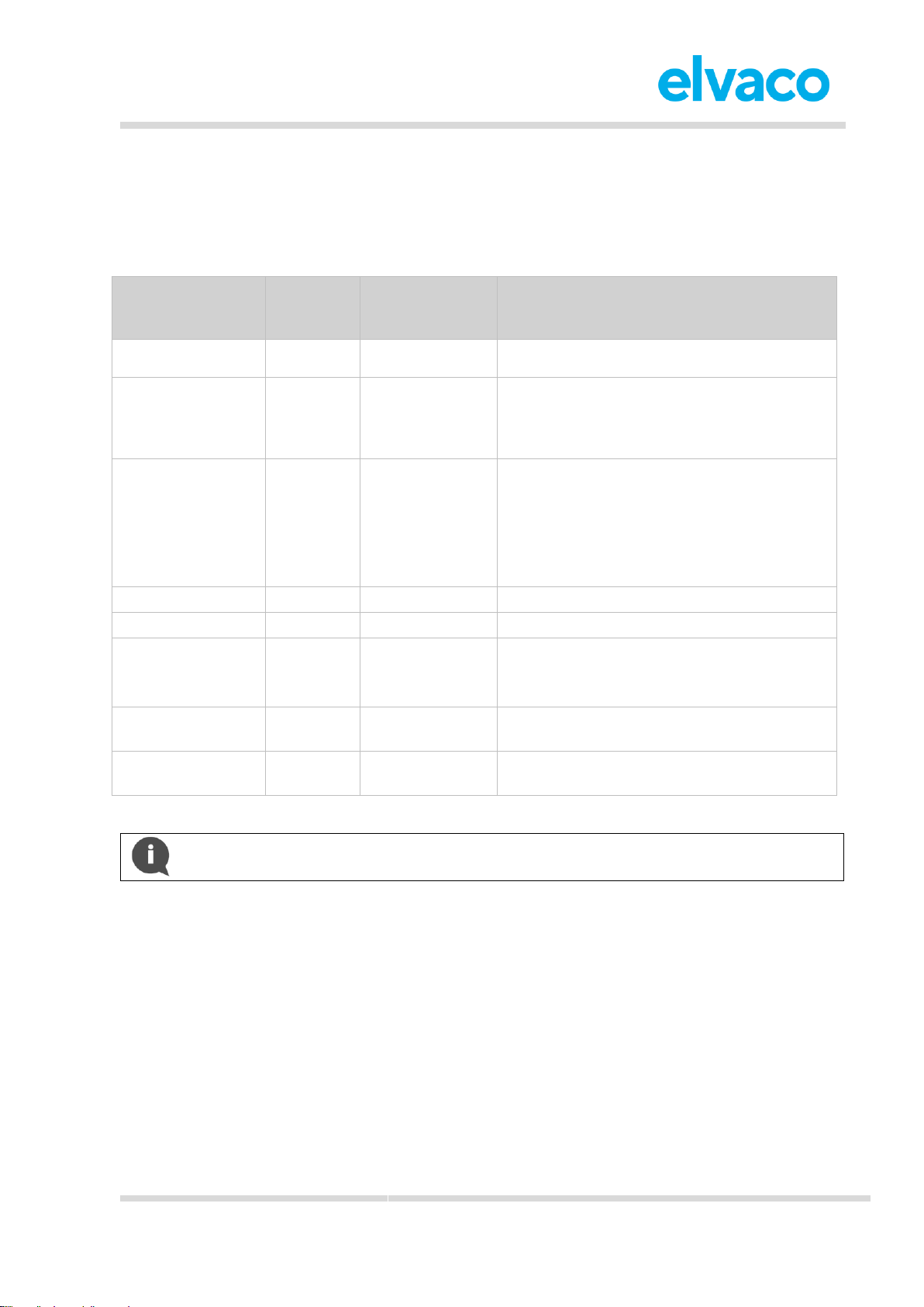
Downlink are sent on port 2, structured according to the following format: “0x00” "TLV" "Number of bytes
in configuration" "Configuration". For a complete description of all available downlink commands, see
Table 13.
Field name
TLV (Type
Length
Value)
Number of
bytes in
configuration
Configuration
Configuration lock
0x05
0x01
0x00 = Locked
0x01 = Open
Transmit interval
(only applies when
EcoMode is
inactive)
0x06
0x02
0xNumber of minutes (lsByte -> msByte)
Message format
0x07
0x01
0x00 = Message format Standard
0x01 = Message format Compact
0x02 = Message format JSON
0x03 = Message format Scheduled-daily
redundant
0x04 = Message format Scheduled-extended
Date & Time
0x11
0x02
0xHHMM
Set Date
0x12
0x03
0xYYMMDD
Set Time Relative
0x13
0x02
0xNumber of minutes*
*Negative numbers supported.
EcoMode
0x0F
0x01
0x00 = Disable EcoMode
0x01 = Enable EcoMode
Maximum daily
transmissions
0x21
0x01
0xNumber of transmissions
Table 13: Downlink commands
Example: To set the MaxDTx parameter to 24, the following command would be sent by
downlink: 0x00 21 01 18
Page 23
CMi4110 User’s Manual English v1.3
CMi4110 User’s Manual English v1.3
page | 23 (27)
[2018-06]
V1.3
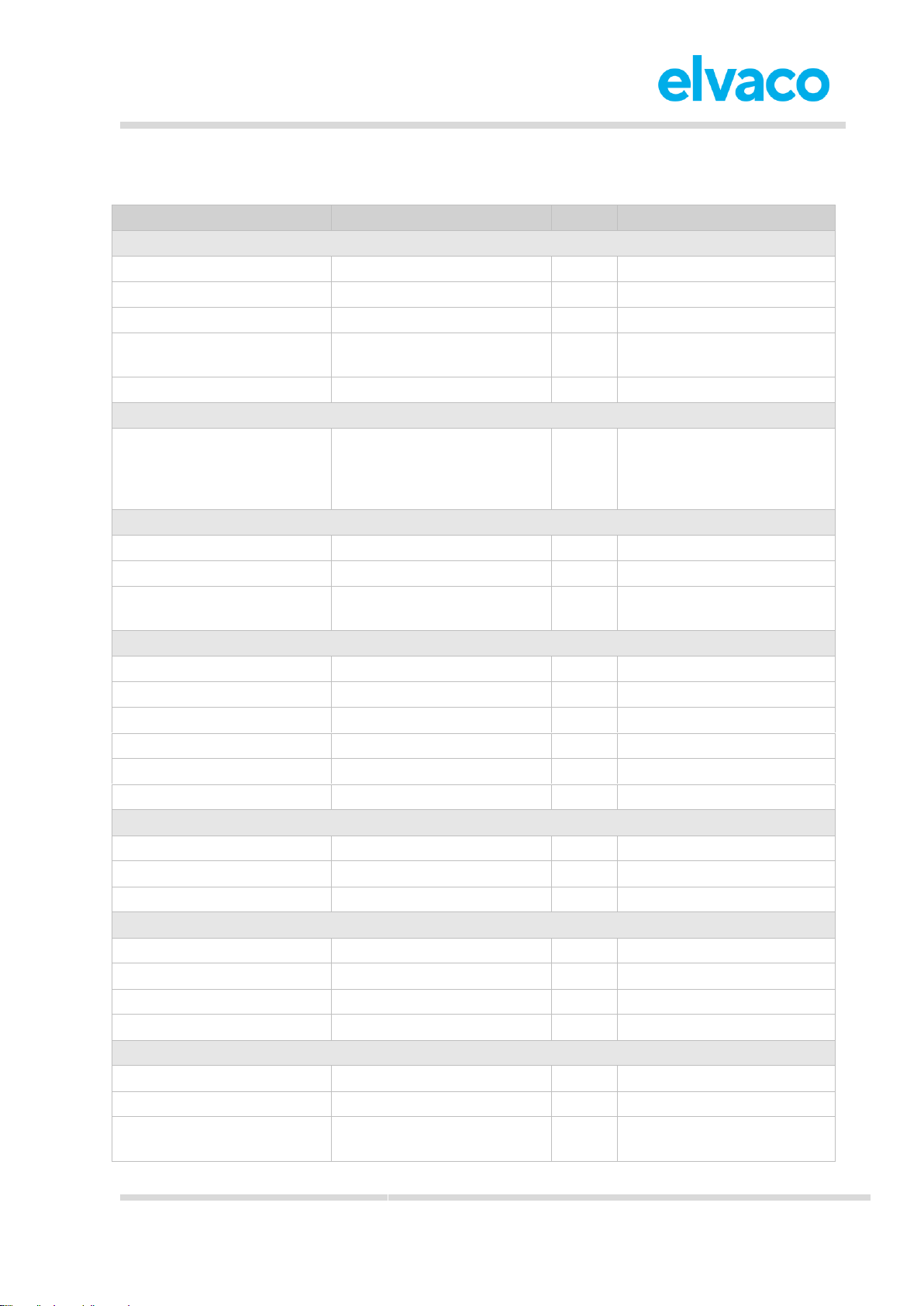
7 Technical specifications
Type
Value
Unit
Comments
Mechanics
Protection class
IP54
-
Dimensions (w x h x d)
80 x 38 x 23
mm
Weight
35 g
Mounting
In Landis+Gyr UH50/UC50
module slot 2
External antenna connector
SMA female
-
Electrical connections
Supply voltage
Internal meter battery or PSU
-
PSU options: Elvaco
CMip2110 230V, Landis+Gyr
WZU-AC230-xx or WZUACDC24-00
Electrical characteristics
Nominal voltage
3.0 - 5.0
VDC
Power consumption (max)
40
mA
Power consumption (sleep
mode)
2.2
µA
Environmental specifications
Operating temperature
5 - 55
ºC
Operating humidity
0 - 93
% RH
No condensation
Operating altitude
2000
m
Pollution degree
Degree 1
-
Usage environment
Indoors
-
Storage temperature
-20 - 60
ºC
Radio characteristics
Frequency
868
MHz
Output power
14
dBm
Receiver sensitivity
-135
dBm
LoRaWAN characteristics
Device class
Class A
-
Bi-directional
LoRa version
1.0 -
Activation
OTAA or ABP
-
Data rate
DR0 - DR5
-
250 – 5470 bit/s
User interface
Green LED
Status
-
Red LED
Error
-
Push button
Start-up / reboot / switch off
module
-
Page 24

CMi4110 User’s Manual English v1.3
CMi4110 User’s Manual English v1.3
page | 24 (27)
[2018-06]
V1.3
Configuration
NFC via Elvaco OTC app or
downlink data
-
Page 25
CMi4110 User’s Manual English v1.3
CMi4110 User’s Manual English v1.3
page | 25 (27)
[2018-06]
V1.3
8 Type approvals
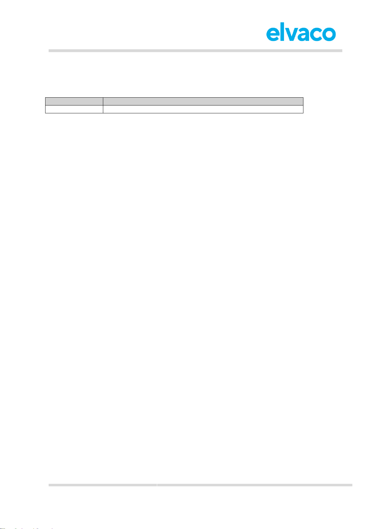
CMi4110 is designed to comply with the directives and standards listed below.
Approval
Description
EMC
EN 301 489-1, EN 301 489-3
Page 26
CMi4110 User’s Manual English v1.3
CMi4110 User’s Manual English v1.3
page | 26 (27)
[2018-06]
V1.3
9 Document history
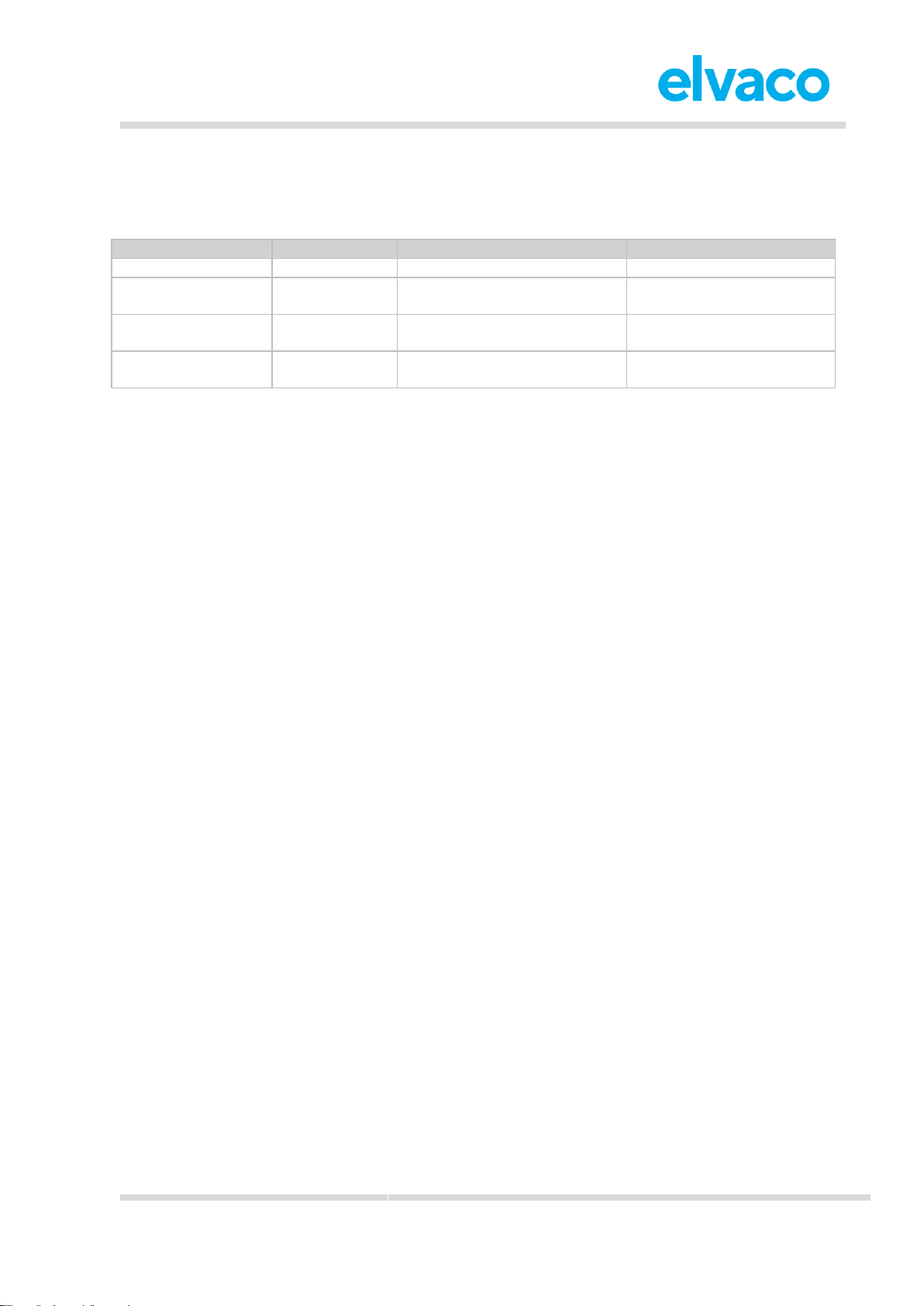
9.1 Versions
Version
Date
Description
Author
v1.0
2018-07
Initial version
Anton Larsson
v1.1
2018-10
Information about Scheduled –
extended added
Anton Larsson
v1.2
2019-03
Corrected DIF/VIF for energy
DIB
Anton Larsson
v1.3
2019-04
Added information about
EcoMode
Anton Larsson
Page 27
CMi4110 User’s Manual English v1.3
CMi4110 User’s Manual English v1.3
page | 27 (27)
[2018-06]
V1.3
10 References
10.1 Terms and abbreviations
Abbreviation
Description
DIB
Data Information Block
DIF
Data Information Field
VIF
Value Information Field
MCM
Meter Connectivity Module
10.2 Number representation
• Decimal numbers are represented as normal number, i.e. 10 (ten).
• Hexadecimal numbers are represented with prefix 0x, i.e. 0x0A (ten)
• Binary numbers are represented with prefix 0b, i.e. 0b00001010 (ten)
 Loading...