

ELVA-1 PPC-10G 2+0, PPC-10G-Q, PPC-10G-E, PPC-10G-E-HP, PPC-10G-Q-HP Installation And User Manual
...Page 1
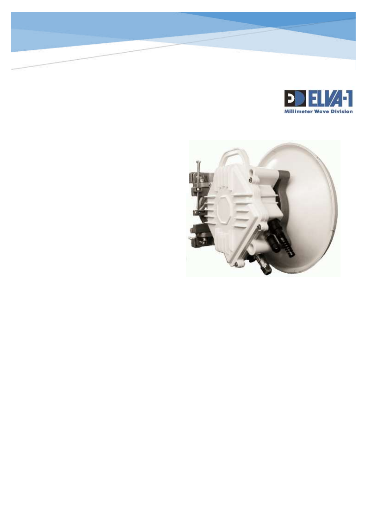
ELVA-1 Microwave HB
INSTALLATION AND USER MANUAL
10 Gigabit Ethernet Wireless Link
For any request regarding this Manual, ccontact us by E-mail: [email protected]
All information from this Manual is protected by the related copyright,
patent, or intellectual property right.
ELVA-1 has the exclusive right to change this information in order to
improve performance or usability of the described products.
PPC-10G is a trademark of ELVA-1. All other trademarks or product names are the
property of their respective owners.
Copyright © 2016-2019, ELVA-1
PPC-10G
PPC-10G HIGH POWER
PPC-10G 2+0
FOR FREQUENCY BANDS
71–76/81–86 GHZ
40.5–43.5 GHZ
Page 2

PPC-10G Installation and User Manual
1
Contents
1. COPYRIGHT AND STATEMENTS 4
1.1 Copyright information 4
1.2 Warranty and Liability 4
1.3 Other Vendor Product Compatibility 5
1.4 Installation and Operation Precautions 5
2. INTRODUCTION 6
2.1 PPC-10G Link Applications 6
2.2 PPC-10G Features 7
2.3 Product Code Format 7
2.4 Regulatory Information 8
2.5 Link Management 8
2.6 User Manual Notes 8
3. DELIVERY KIT 9
3.1 Delivery Kit Overview 9
3.2 Tools and Accessories in Mounting Kit 10
4. PREPARING THE SITE OF INSTALLATION 11
4.1 Unpacking the PPC-10G and Examining Delivery Kit 11
4.2 Examining the Site of Installation 11
4.3 Path Planning 12
4.4 Minimal Clearance for Fresnel zone 12
4.5 Supporting Structure for Transceiver 13
4.6 Stationary Cabling on Installation Site 14
5. INSTALLATION OF TRANSCEIVER 17
5.1 Radio Assembling and Installation Sequence 17
5.2 Final Antenna Alignment 21
5.3 Understanding of Alignment and Operational Modes of Transceiver 24
6. USING WEB INTERFACE FOR FIRST-TIME LINK SETUP 25
6.1 Understanding Web Interface Connection to Radios 25
6.2 First Time Connection to Radios at Both Sides of the Link 26
6.3 Login to Radios and Initial Setup 27
7. 2+0 LINK ASSEMBLING, INSTALLING AND SETUP 31
7.1 PPC-10G 2+0 Unpacking 31
Page 3

PPC-10G Installation and User Manual
2
7.2 Assembling and Installation of 2+0 Link 32
7.3 Antenna alignment for 2+0 Link 35
7.4 Login to 2+0 Radios and Initial Setup 35
8. MAINTENANCE AND TROUBLESHOOTING 36
9. APPENDIX A 37
9.1 PPC-10G Specifications 37
9.2 PPC-10G-HP Specifications 38
9.3 PPC-10G /2+0 Specifications 39
9.4 PPC-10G / PPC-10G-HP Drawing 40
9.5 PPC-10G / 2+0 Drawing 41
Page 4

PPC-10G Installation and User Manual
3
List of Illustrations
Fig. 1 PPC-10G link at the point of installation ...................................................................... 6
Fig. 2 PPC-10G product code legend (mind L2 link is not covered in this Manual) ...................... 7
Fig. 3. Delivery package (typical) ........................................................................................ 9
Fig. 4. Antenna package .................................................................................................... 9
Fig. 5. Transceivers and accessories boxes .......................................................................... 9
Fig. 6. Examining LoS...................................................................................................... 11
Fig. 7. Antenna radiation pattern is an elongated cone with side lobes in reality ..................... 12
Fig. 8. Clearance in Fresnel zone ...................................................................................... 12
Fig. 9. Photos of PPC-10G can be installed on vertical or horizontal pipe ................................ 13
Fig. 10. Stationary cable layout diagram ............................................................................ 14
Fig. 11. Connectors in Mounting Kit for each PPC-10G radio (included to delivery) .................. 14
Fig. 12. Cross-connection box with power, UTP and fiber cables to transceiver ....................... 15
Fig. 13. DC power connector pins ..................................................................................... 15
Fig. 14. Transceiver sockets (#1, #2, #3, #4) ................................................................... 16
Fig. 15. Transceiver and tools at site of installation. ............................................................ 17
Fig. 16. It is more easy to put the antenna on top of the pipe than reassemble the mount to “hug”
the pipe ......................................................................................................................... 17
Fig. 17. A plastic tie strip tightening on the pipe stand will not allow the mount to slip down during
installation procedure and thus prevents antenna from possible damage ............................... 18
Fig. 18.. Remove protective tape waveguide hole on antenna and transceiver ........................ 18
Fig. 19. Check for “H” and “V” polarization labels on antenna ............................................... 18
Fig. 20. Photo of V-polarization (left) and H-polarization (right) red label ............................... 19
Fig. 21. Position of sockets to be directed down, not up ....................................................... 19
Fig. 22. Grounding wire position ....................................................................................... 20
Fig. 23. RSL meter indicates -99.9 if the antenna is not aligned to opposite one ..................... 20
Fig. 24. Antenna radiation pattern has central beam and side lobes ...................................... 21
Fig. 25. The technicians should coordinate their antenna adjustments on both sides of the link 21
Fig. 26. Antennas A and B to an alignment that is above (B) and below (A) the LOS. .............. 22
Fig. 27. Check RSL meter indication when running alignment procedure ................................ 22
Fig. 28. During antenna alignment, RSL indication should change from -99 to actual “RSL at
alignment mode’ value for your distance according Link Budget Calculator (see
http://linkbudgetcalc.elva-1.com ) .................................................................................... 22
Fig. 29. Diagram for relevance of RSL meter indication to antenna side lobes ......................... 23
Fig. 30. Wireless channel throughput at different weather conditions for 70/80 GHz band when
using adaptive modulation .............................................................................................. 24
Fig. 31. PPC-10G radios LAN / WAN web access connectivity – over LAN at each side or over the
Internet ......................................................................................................................... 25
Fig. 32. Example of PPC-10G label with Hi symbols on the back of the radio body ................... 25
Fig. 33. Case of admin connection to both radios with backup channel .................................. 26
Fig. 34. Case of admin connection to each radio while there is NO backup channel ................. 27
Fig. 35. Login as Installer with default password 111111 ..................................................... 28
Fig. 36. Press the Operational radio button ........................................................................ 28
Fig. 37.Change password for Web Interface access to this radio ........................................... 29
Fig. 38. Check and if necessary adjust actual time settings for the radio ................................ 29
Fig. 39. Change IP address of the radio from default to actual one ........................................ 30
Fig. 40. 2+0 package with transceivers and accessories ...................................................... 31
Fig. 41. 2+0 package with antenna and dual polarization adapter ......................................... 31
Fig. 42. Two transceivers assembled with dual polarisation adapter ...................................... 32
Fig. 43. Mind polarisation label on DPA .............................................................................. 32
Fig. 44. Install 3 bolts on positions of “5, 15 and 35 minutes“ on the antenna flange .............. 33
Fig. 45. Use 6 bolts to screw diplexer to antenna flange ...................................................... 33
Fig. 46. Do not allow the appearance of an uneven gap between the antenna and the diplexer . 34
Fig. 47. Adjust the diplexer rotation using the element marked by red oval ............................ 34
Page 5

PPC-10G Installation and User Manual
4
1. COPYRIGHT AND STATEMENTS
1.1 COPYRIGHT INFORMATION
All information from this Manual is protected by the related copyright, patent, intellectual property
right.
The products and software stated in this document can’t be translated into another language by
arbitrary forms or ways without written consent of ELVA-1 Microwave HB (further also mentioned
as ELVA-1) and can’t be photocopied or scanned into a storage or cloud media.
ELVA-1 has an exclusive right to change this information in matter to improve performance or
usability of the described products.
ELVA-1 PPC-10G is trademarks of ELVA-1 Microwave HB. All other trademarks and product names
mentioned in this manual are belonged to their respective owners.
1.2 WARRANTY AND LIABILITY
Elva-1 Microwave HB warrants each standard Elva-1 Microwave HB product sold by it to be free of
defects in material and workmanship under conditions of normal use for twelve (12) months from
date of shipment thereof to Buyer. Repair or, at Elva-1 Microwave HB’s option, replacement of
defective parts shall be the sole and exclusive remedy under this limited warranty. All warranty
replacement or repair of parts shall be limited to equipment malfunctions, which, in the sole opinion
of Elva-1 Microwave HB, are due or traceable to defects in original materials or workmanship.
In the event the Buyer believes that the Product is covered by the limited warranty of this Section,
the Buyer shall pay for the shipping and insurance of such Product to Elva-1 Microwave HB.
If Elva-1 Microwave HB determines in its sole opinion that such Product does conform to the limited
warranty, then Elva-1 Microwave HB shall pay for the shipping and insurance of repaired or
replacement Product back to the Buyer. However, in the event that Elva-1 Microwave HB
determines in its sole opinion that such Product is not covered by the limited warranty, Buyer shall
pay for shipping and insurance of such Product back to the Buyer.
All obligations of Elva-1 Microwave HB under this limited warranty shall cease in the event of abuse,
accident, alteration, misuse or neglect of the Product. In-warranty repaired or replaced parts are
warranted only for the remaining unexpired portion of the original warranty period applicable to
the repaired or replaced parts.
REASONABLE CARE MUST BE USED TO AVOID HAZARDS. ELVA-1 MICROWAVE HB EXPRESSLY
DISCLAIMS RESPONSIBILITY FOR LOSS OR DAMAGE CAUSED BY USE OF ITS PRODUCTS OTHER
THAN IN ACCORDANCE WITH PROPER OPERATING PROCEDURES.
THE FROEGOING LIMITED WARRANTY FOR ELVA-1 MICROWAVE HB PRODUCTS IS EXPRESSLY IN
LIEU OF, AND EXCLUDES ALL OTHER EXPRESS OR IMPLIED WARRANTIES, INCLUDING BUT NOT
LIMITED TO WARRANTIES OF MERCHANTABILITY AND OF FITNESS FOR PARTICULAR PURPOSE,
USE OR APPLICATION, AND ALL OTHER OBLIGATIONS OR LIABILITIES ON THE PART OF ELVA-1
MICROWAVE HB, UNLESS SUCH OTHER WARRANTIES, OBLIGATIONS OR LIABILITIES ARE
EXPRESSLY AGREED TO IN WRITING BY ELVA-1 MICROWAVE HB. Statements made by any person,
including the representatives of Elva-1 Microwave HB, which are inconsistent or in conflict with the
terms of these warranties shall not be binding upon Elva-1 Microwave HB unless expressly reduced
to writing and approved by an officer of Elva-1 Microwave HB.
Page 6

PPC-10G Installation and User Manual
5
1.3 OTHER VENDOR PRODUCT COMPATIBILITY
While every effort has been made to verify operation of this product with many different
communications products and networks, ELVA-1 makes no claim of compatibility between its
products and other vendors’ equipment. It is assumed that users have thoroughly evaluated this
product’s performance in the communications and other engineering environment in which it will
be used.
1.4 INSTALLATION AND OPERATION PRECAUTIONS
The following general safety precautions must be observed during all phases of operation and
service of the products will fully violates standards of design, manufacture, and intended use of
the product. Elva-1 Microwave HB assumes no liability for the customer’s failure to comply with
these requirements.
• Do not operate wireless equipment without an appropriate termination.
• Do not work directly in front of energized antenna.
Prior to working on the antenna or RF assembly, ensure that the RF assembly is not radiating
energy. When power is applied to the RF assembly and antenna, power precautions must be taken
to avoid placing any part of the human body in front of the antenna.
• The outdoor equipment must be properly grounded to provide protection against voltage surges
and built-up static charges. In the event of a short circuit, grounding reduces the risk of electrical
shock.
For installations in the USA, refer to Articles 810830 of the National Electrical Code, ANSI/NFPA,
for information with respect to proper grounding and applicable lightning protection for DC cables.
For installations in all other countries, implement protection in accordance with the safety
standards and regulatory requirements of the country where the equipment is to be installed.
• Do not install or operate this equipment in the presence of flammable gases or fumes. Operation
of any electrical instrument in such an environment constitutes a definite safety hazard.
• Do not install substitute parts or perform any unauthorized modification to the equipment.
Changes or modifications not expressly approved by Elva-1 Microwave HB void the Warranty on
the equipment.
• This product is designed to withstand moisture conditions typically encountered when installed
outdoors. This is not designed for operation under water.
• This product is not designed to withstand direct thunderbolt. It should be operated only under
protection of external lightning rod.
• This product should be operated only from the type of power source indicated on the equipment
or in this manual.
Page 7
PPC-10G Installation and User Manual
6
2. INTRODUCTION
2.1 PPC-10G LINK APPLICATIONS
The РРС-10G wireless link is intended for full duplex 10 Gigabit Ethernet radio communication
between two locations. It is comprised of two subscriber transceivers, each operating under lineof-sight conditions at working frequencies within the 71/86 GHz or 40.5-43.5GHz radio bands.
This link is intended for point-to-point digital communications applications such as 4G/LTE/5G
Mobile Backhaul, Corporate Campus Networks, IPTV, and Wireless ISP backbones. It is designed
to wirelessly interconnect WAN/LAN segments that are located at sites with no fixed line broadband
connection. Such sites typically contain landscape or industrial barriers, or strict ecological,
geographical or climate restrictions for ground cable trenching, like deep-frozen soil Arctic regions,
national parks, rivers, lakes, airport/railway areas, private land, etc.
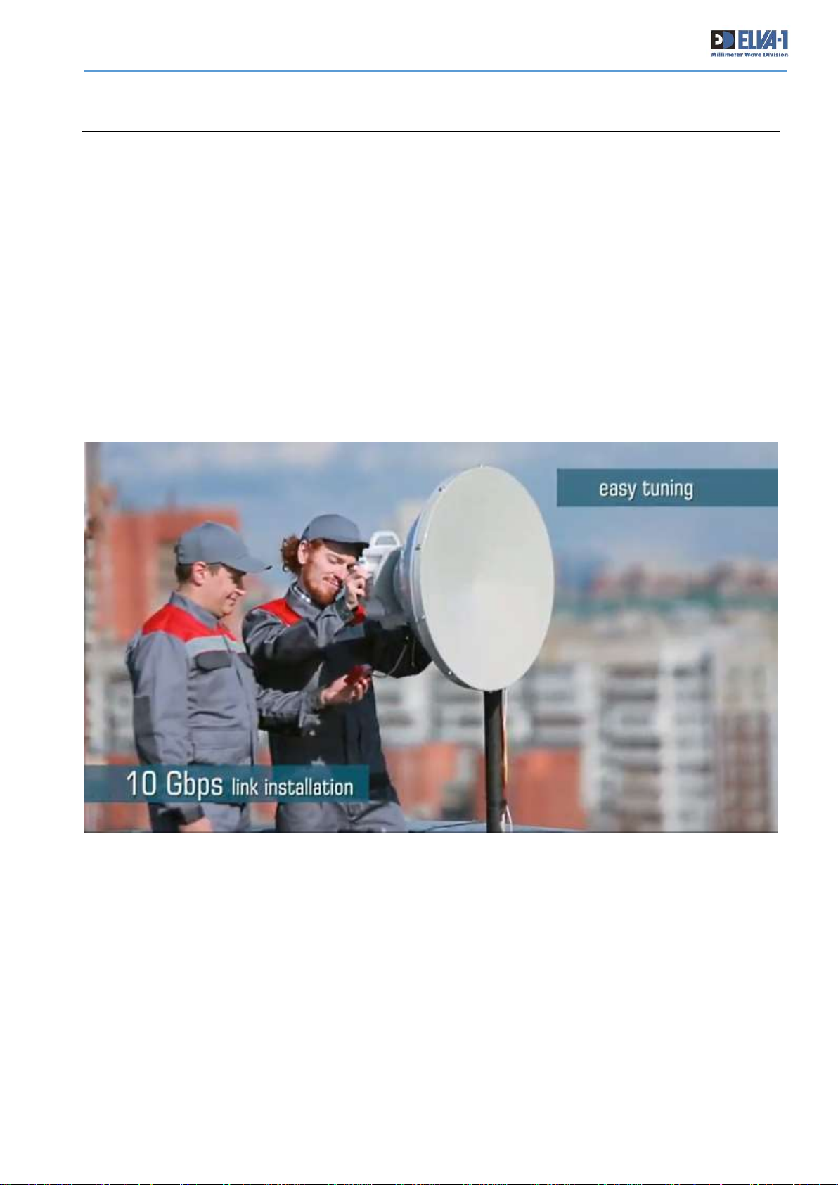
Fig. 1 PPC-10G link at the point of installation
PPC-10G is available in either lightly licensed 71-76/81-86 GHz (E-band) or licensed 40.5-43.5
GHz (Q-band) or frequency formats. The radios are equipped with 60 cm (2 ft.) antennas by
default; however, smaller antenna sizes are also available. The PPC-10G is normally mounted in a
rooftop or tower location, and contains slots for SFP/SFP+ modules to connect to a LAN/WAN
network.
The ELVA-1 PPC-10G is a fully-outdoor radio link, designed for temperature variations between
-50°C (-58°F) and +60°C (148°F), and humidity up to 100%. The reliable operating distance is up
to 10 km (6 mi) for links equipped with 60 cm antennas. This distance is valid for regions like North
Page 8
PPC-10G Installation and User Manual
7
America or continental Europe. For regions with clear weather year-round, like the Middle East,
the distance would be much longer.
2.2 PPC-10G FEATURES
• Frequency band: 71-76/81-86 GHz or 40.5-43.5 GHz
• SNMP v.2; MIB-II; IP-MIB; IF-MIB and Enterprise MIB; WEB
• True Full Duplex Operation
• Hitless adaptive bandwidth, coding and modulation
• IEEE 1588v2 (TC)
• Encryption AES-128 optionally
• Solid reliability with Fiber-like Performance
• Easily installed, zero-footprint
• Compact Cassegrain type antennas
• Quasi-optical (laser-like) millimetre wave propagation
• EMI interference free
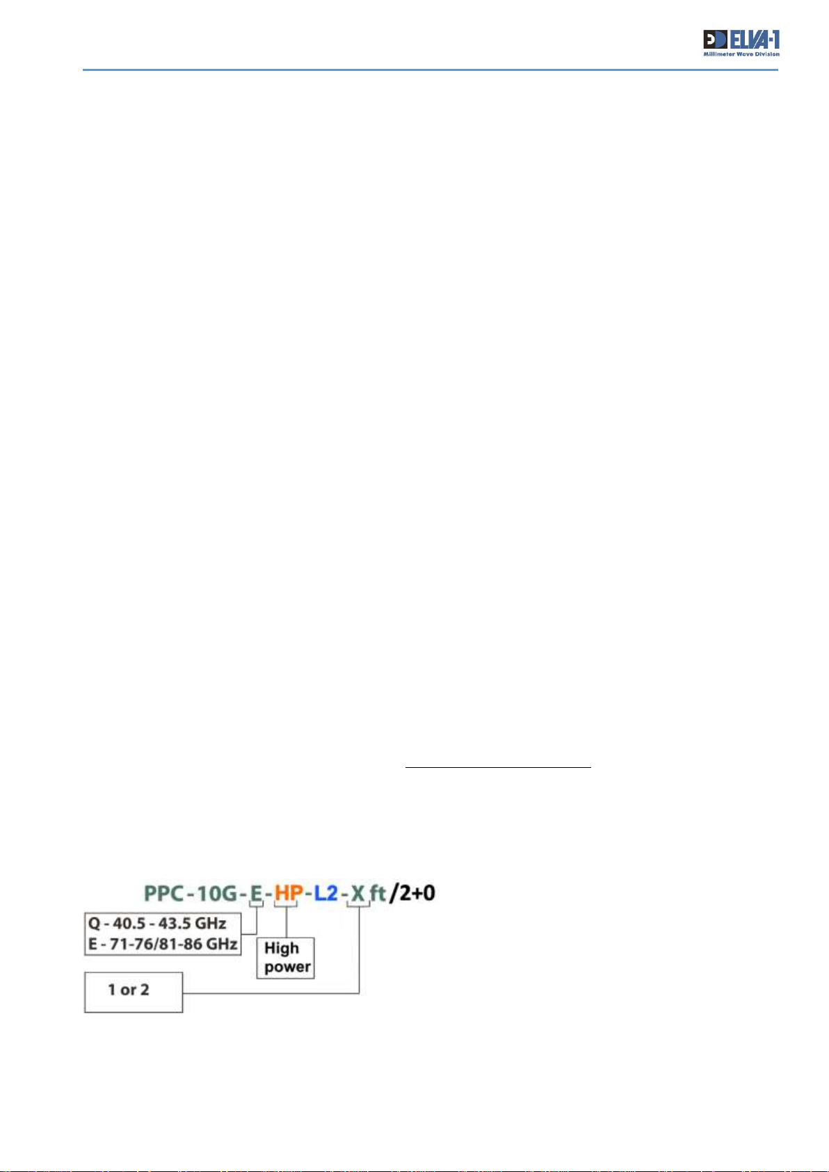
2.3 PRODUCT CODE FORMAT
Wide choice of modification of the radio are available, including
1. Basic 10Gbps PPC-10G link,
2. PPC-10G link with high-power transmitter,
3. PPC-10G link with built-in L2+ switch (not covered in this Manual),
4. PPC-10G link for 2+0 aggregated channels 20 Gbps.
There is possibility of combining some of these features in one radio by customer order.
To order the right model by its product code, please use the following encoding schema:
Fig. 2 PPC-10G product code legend (mind L2 link is not covered in this Manual)
Page 9

PPC-10G Installation and User Manual
8
For example, basic PPC-10G link with 2ft antennas, 71-76/81-86 GHz band has code
PPC-10G-E-2ft.
• To have L2+ switch option please add “L2” to code.
• To have HP (High Power) option please add “HP” to code
• To have 2+0 aggregation option please add “/2+0” to code
Notes: For HP (High Power) radio, its central frequency is factory preset (not tunable by user),
please advise its value at order.
2.4 REGULATORY INFORMATION
Links installed in the U.S. must be registered with the FCC according to product ID assigned by
the FCC to identify this wireless product in the market. The FCC chooses 3 or 5 character "Grantee"
codes to identify the business that created the product.
ELVA-1 grantee code is 2AIXT, for PPC-10G radios FCC ID: 2AIXT-PPC-10G-E. The
remaining characters of the FCC ID, -PPC-10G-E, are associated with the product model.
These letters are chosen by the applicant.
For use in EU countries ELVA-1 PPC-10G 70/80 GHz 10Gbps MMW Link has been examined for
compliance to 2014/53/EU Radio Equipment Directive (RED) at Washington Laboratories, Ltd.
To download FCC Certificate and Declaration of Conformity to 2014/53/EU Radio Equipment
Directive (RED) please visit ELVA-1 web site at http://www.elva-1.com/downloads.
2.5 LINK MANAGEMENT
An operator could manage PPC-10G link of any modification using its web-based interface. Basic
information on web-based interface to start the link at first time is available in this manual.
To understand all PPC-10G features and wide range of built-in indicators and diagnostic tools please
refer to PPC-10G Web Interface Manual. It is available any time on request to [email protected].
2.6 USER MANUAL NOTES
This Manual covers PPC-10G, PPC-10G-HP and PPC-10G/2+0 links.
The PPC-10G and PPC-10G-HP are identical in dimensions, controls, delivery kit and other
appearance. Read all chapters excluding “Chapter 7” for assembling, installation and IP setup of
PPC-10G and PPC-10G-HP links.
For PPC-10G/2+0 links assembling, installation and IP setup read all chapters, then pay attention
to Chapter 7 which is especially devoted to PPC-10G/2+0 link.
Page 10
PPC-10G Installation and User Manual
9
3. DELIVERY KIT
3.1 DELIVERY KIT OVERVIEW
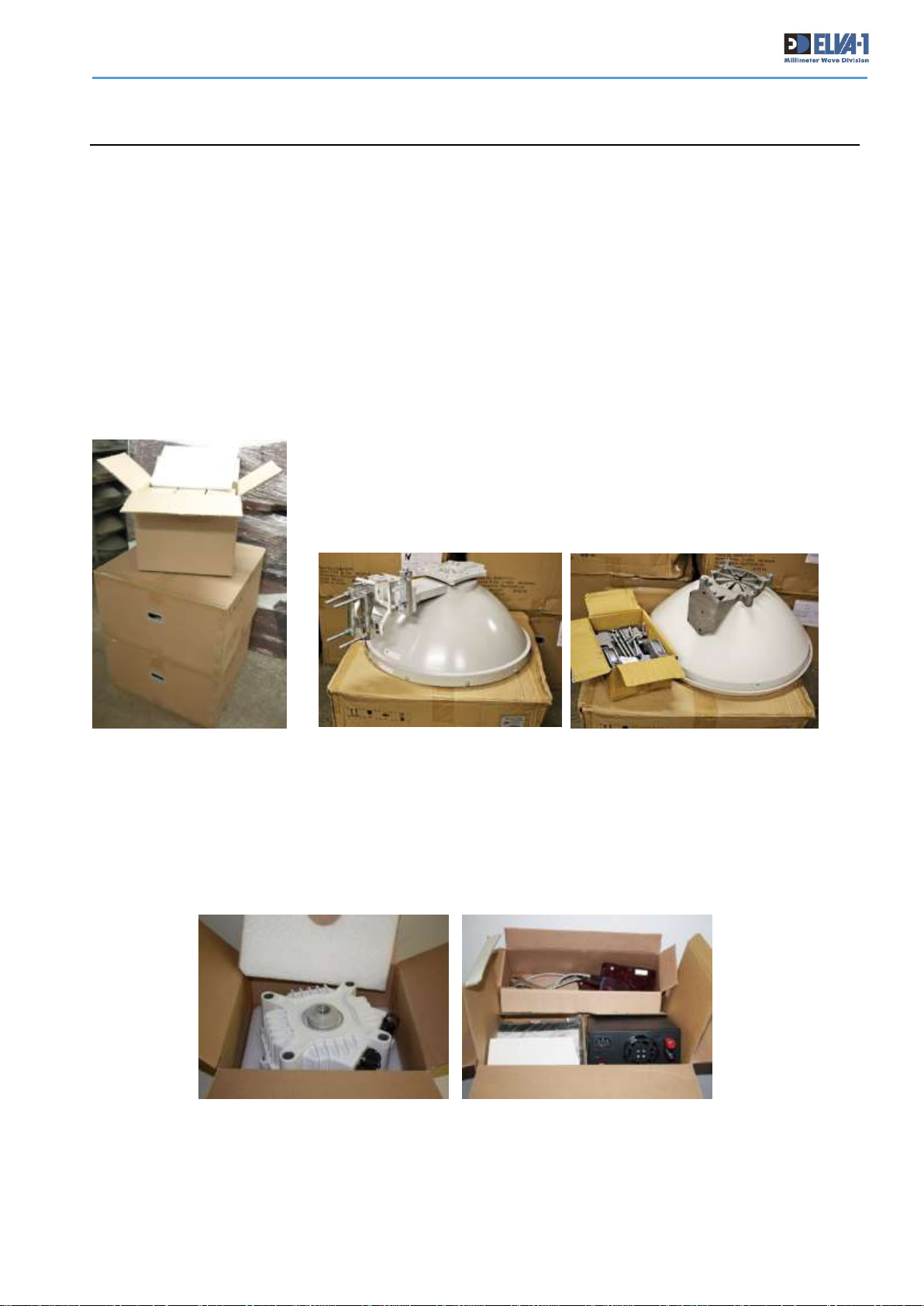
The PPC-10G equipment will arrive in 3 or more boxes, the sizes of which will depend on antenna
diameter.
For all modifications of radios excluding “2+0”, two of the boxes will contain the antennas and
mounting/alignment brackets, and the other box will contain two transceivers and accessories
(cables, connectors, tools, etc.), see Fig. 3.
For “2+0”modification, there is one more box with two additional transceivers inside, see
Chapter 7 for details.
Each antenna box will contain one antenna, an antenna cover and a
mounting/alignment bracket. Depending on the antenna configuration,
the alignment bracket could already be mounted to the antenna as a
complete unit (Fig.4, left photo) or be enclosed in the box as separate
accessory package (Fig.4, right photo).
If the alignment bracket is enclosed in a separate accessory package,
it must be assembled and mounted to antenna in accordance with the
printed manual that is enclosed in the box.
The box with transceivers contains 3 smaller boxes inside. Two of them contain transceivers
(Fig.5, left photo) and one with doubled kit of power units, cables, sockets, tools, RSL meter
(Fig.5, right photo).
The factory recommends that the shipping boxes and packing materials be retained by the
customer at least for the length of the warranty (12 months), or longer.
Fig. 3. Delivery package
(typical)
Fig. 4. Antenna package
Fig. 5. Transceivers and accessories boxes
Page 11
PPC-10G Installation and User Manual
10
Table 1. Packing list for radios
Description
Quantity
Transceiver module
2 (4*)
600** mm antenna with radio-transparent radome and mount
2
Power Supply unit
2 (4*)
Diplexer with 6x hex. bolts (for 2+0 modification only)
2
Mounting kit (tools, accessories)
2
* For PPC-10G 2+0 modification Delivery Kit includes 4x Transceiver modules and 4x Power Supply
units.
** Antenna size is shipped according to the customer order, 600 mm antenna is basic, while there
is other size of 300 mm in diameter for short-range application.
This User Manual and Manual for Web Interface are usually delivered to customer via the Internet
in electronic format.
3.2 TOOLS AND ACCESSORIES IN MOUNTING KIT
There are connectors, tools and cables within Mounting kit to easily install PPC-10G link.
Table 2. ACCESSORIES list
Description
Quantity
RSL meter unit
2
SFP-Plus-LR.LC.10 module
2 (4*)
Cable to 110-240 VAC main for ESP-240-54 Power Supply unit
2 (4*)
106059-7700 Fibre Optic Connector LC SM
2
130057-0003 Sealed Ethernet, RJ-45, Cable Connector
2
120071-0036 Micro-Change (M12) 4 Contacts Connector for power in
2
Hexagon Socket Bolt DIN 912 M8
8
Lock Washer DIN6798J A2 М8
8
6mm Metric Allen Wrench Key (hex key)
2
17 Ring & Open Ended Wrench
2
* For PPC-10G 2+0 modification Mounting kit only.
Page 12
PPC-10G Installation and User Manual
11
4. PREPARING THE SITE OF INSTALLATION
ELVA-1 assumes that customer personnel has an understanding of mm-wave wireless technology
and sufficient familiarity with configuring and operating LAN/WAN networking equipment.
Preferably, the personnel installing PPC-10G fully read and understood the information covered in
this manual before performing any actions with the PPC-10G.
Before starting installation procedure, it is recommended to get familiar with its general sequence:
• Unpacking the PPC-10G and examining Delivery Kit
• Preparing both sites of installation (at both ends of wireless link)
• Mounting the PPC-10G
• Connecting the cables
• Aligning the antenna (for both transceivers)
• Performing initial link setup by web-interface.
4.1 UNPACKING THE PPC-10G AND EXAMINING DELIVERY KIT
It is recommended to unpack PPC-10G at a clean indoor place and examine all parts of delivery for
any mechanical damage during transportation. Report any damages to ELVA-1 or your dealer.
Please mind that hanks of DC power cable, twisted pair cable and optical cable are not included to
delivery kit and have to be purchased from local supplier accordingly to required length.
4.2 EXAMINING THE SITE OF INSTALLATION
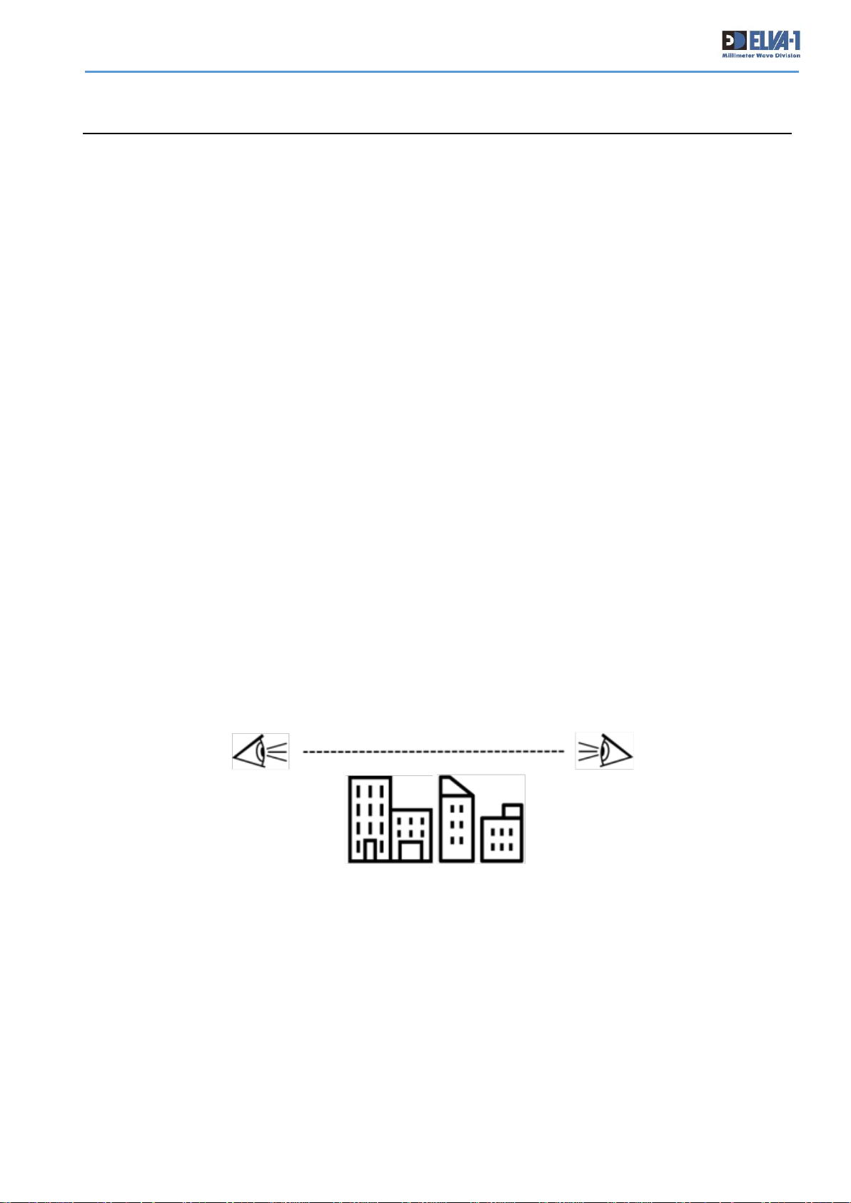
The PPC-10G mm-wave wireless link requires a clear Line-of-Sight (LOS) for proper operation.
That means that no obstacles, such as trees, buildings, chimneys, etc. can obstruct the LOS path
between the transceivers. Moreover, no obstacles should be located in the vicinity of the signal
propagation line (inside the first Fresnel zone).
Site planning should include an investigation into future construction that would block the LOS
path, and other long term incremental obstructions such as growing trees.
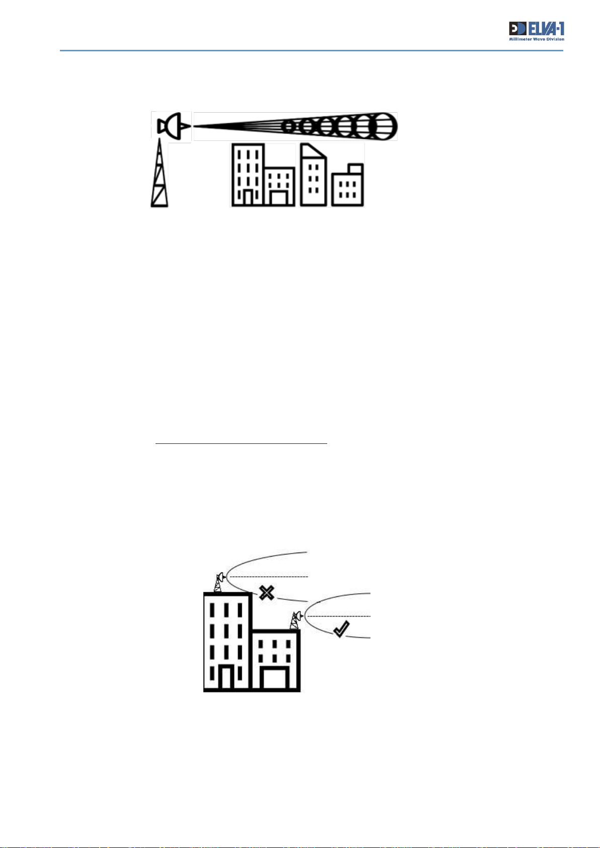
However, it should be understood that due to the physics of the ray divergence process, the
antenna radiation pattern is not an ideal thin straight line, but an elongated cone (with side lobes).
Leaving practically from a point source (from the center of the antenna), the beam cone reaches
a quite significant diameter to the opposite antenna about 30 m at a distance of 3 km, 60 m at 5
Fig. 6. Examining LoS
Page 13
PPC-10G Installation and User Manual
12
km and up to 100 m in diameter at a distance of 8 km and more. Accordingly, such a cone of the
radiation pattern should also not touch any obstacles along the way by its edges.
To ensure PPC-10G equipment is protected from vandalism and theft it must be mounted in a
position that is accessible to only authorized personnel.
4.3 PATH PLANNING
Use Google Maps or another geographical locating tool to obtain the distance between the proposed
transceiver installation points.
Measurement of the link distance is important in calculating of the link availability and Receive
Signal Level (RSL). The link distance measurement can be performed using Global Positioning
System (GPS) device at proposed locations of the transceiver installation. Additionally GPS reading
will be required in order to comply with the FCC registration process.
For estimated link availability and RSL value for your distance please refer to ELVA’s online link
budget calculator http://linkbudgetcalc.elva-1.com/. In case online calculator is not available,
contact ELVA-1 or local dealer to obtain the exact attenuation value for distance between the
transceiver. This value will be your “passport” reference value on the RSL meter device when
conducting the final antenna alignment.
4.4 MINIMAL CLEARANCE FOR FRESNEL ZONE
There must be no obstructions between the antenna and any on-site structure in the so-called first
Fresnel zone. Any obstruction in the first Fresnel zone will corrupt the antenna pattern. In practice,
the antenna should be mounted on the edge of a roof or on a mast, so it propagates the signal
directly into free space.
Fig. 7. Antenna radiation pattern is an elongated cone with side lobes in reality
Fig. 8. Clearance in Fresnel zone
Page 14
PPC-10G Installation and User Manual
13
Fresnel zones are series of concentric ellipsoids surrounding the straight-line path between two
antennas. The radius of the Fresnel zone is greatest at midpoint in the signal path. Minimum
Clearance (i.e., radius of the first Fresnel zone) for various bands is listed in the table.
Table 3. Fresnel zone min clearance
Path Length,
miles/km
Minimum Clearance for Fresnel zone,
ft/meters
Q-band
40.5-43.5 GHz
E-band
71-76/81-86 GHz
0,6 mi / 1 km
4,6 ft / 1,4 m
1,2 ft / 1 m
1,2 mi / 2 km
5,6 ft / 2 m
4,6 ft / 1,4 m
3,1 mi / 5 km
10,5 ft / 3,2 m
7,5 ft / 2,3 m
6,2 mi / 10 km
14,7 ft / 4,5 m
10,2 ft / 3,1 m
4.5 SUPPORTING STRUCTURE FOR TRANSCEIVER
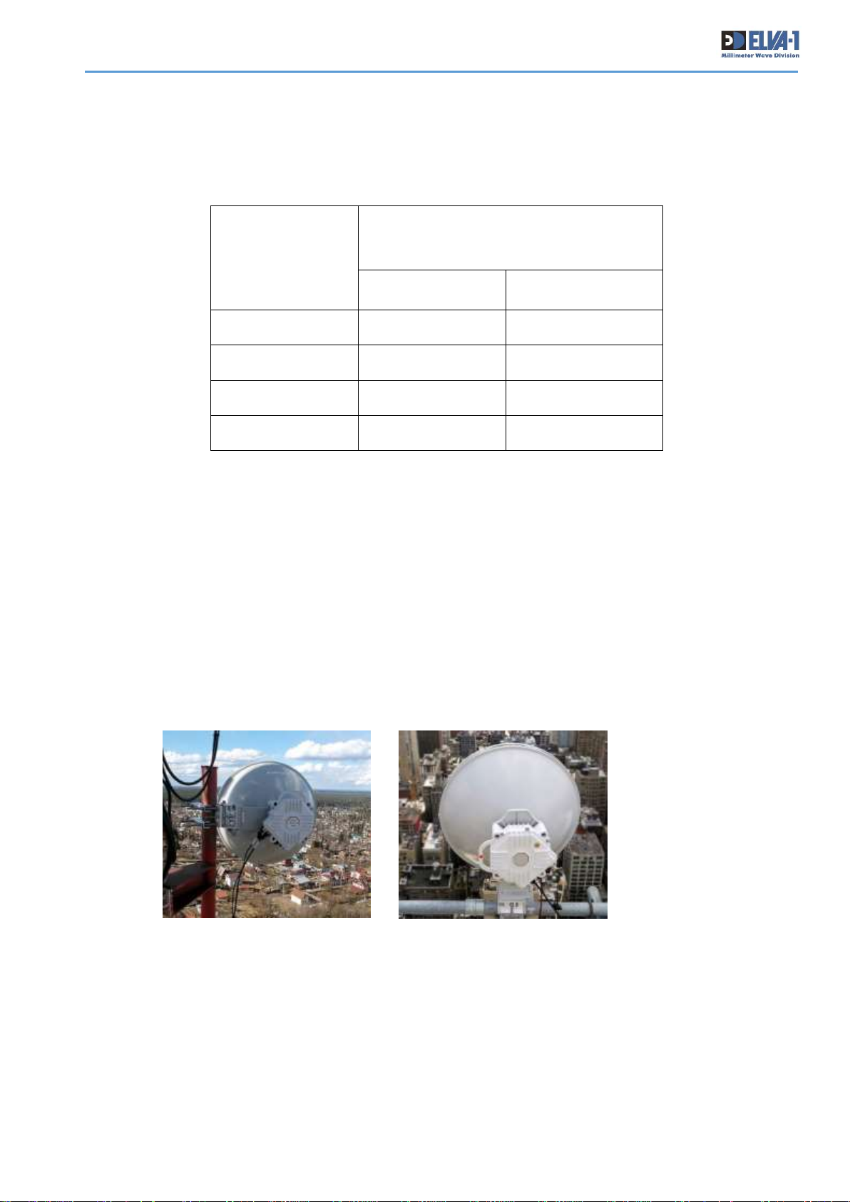
The radio should be fastened to a vertical support pole that is 51 to 114 mm in diameter and not
less than 500 mm (20”) in vertical length. The design of the support structure is not specified,
but its resistance to bending and torsion must be strong enough to prevent antenna movement
in either azimuth or elevation by wind, snow cap or other natural force.
It is allowed to mount the radio to a horizontal pipe of 51 to 1114 mm diameter.
It is necessary to carefully monitor the polarization marks of the antenna, so that both
transceivers are either in the vertical polarization or horizontal position.
Fig. 9. Photos of PPC-10G can be installed on vertical or horizontal pipe
Page 15
PPC-10G Installation and User Manual
14
4.6 STATIONARY CABLING ON INSTALLATION SITE
Before the transceivers with antennas can be installed, connecting cables must be run from the
indoor network equipment (switch, for example) to the outdoor installation point at each site.
Please mind the number of cables has to be doubled for 2+0 radio, see Chapter 7 for details.
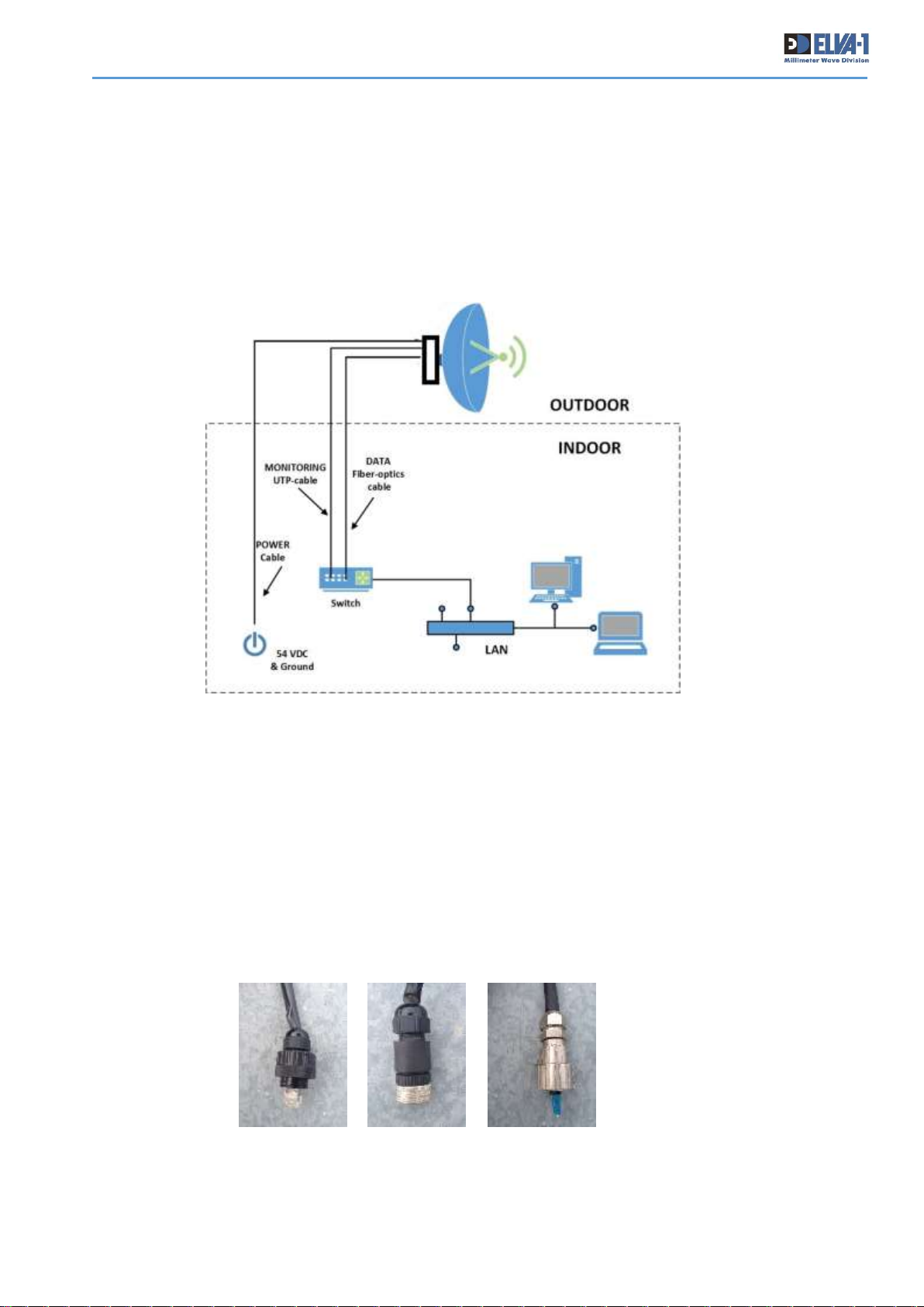
A sample diagram of one transceiver installation layout is shown below. To avoid EMI noise, the
low-voltage power supply and UTP data cables must be kept away from stationary 110-240 V AC
power cables.
The installation site should be inspected to determine the run paths for the fiber cable, twisted pair
cable, DC power cable and grounding wire from the proposed radio location to the termination
point. Locations for roof penetration should be identified. The routing and securing of all cables
should conform to all applicable codes and requirements.
Cabling conduit may be required depending on the likelihood of damage due possible reasons. The
maximum cable run length must not be exceeded as specified for type of the cable.
Unpack the Mounting Kit and get familiar yourself with connectors for each radio. They includes
the following:
Fig. 10. Stationary cable layout diagram
Fig. 11. Connectors in Mounting Kit for each PPC-10G radio (included to delivery)
1 2 3
Page 16
PPC-10G Installation and User Manual
15
1. RJ-45 Connector "MONITORING" for cable of WEB-monitoring
2. Power connector "POWER" for 36-60 V DC power cable
3. SFP/SFP + "DATA" connector for 10 Gbps data transmission cable
When installing cables outdoor, allow power and data cables with service loop for strain relief and
proper fiber bend radius when determine the length of each cable.
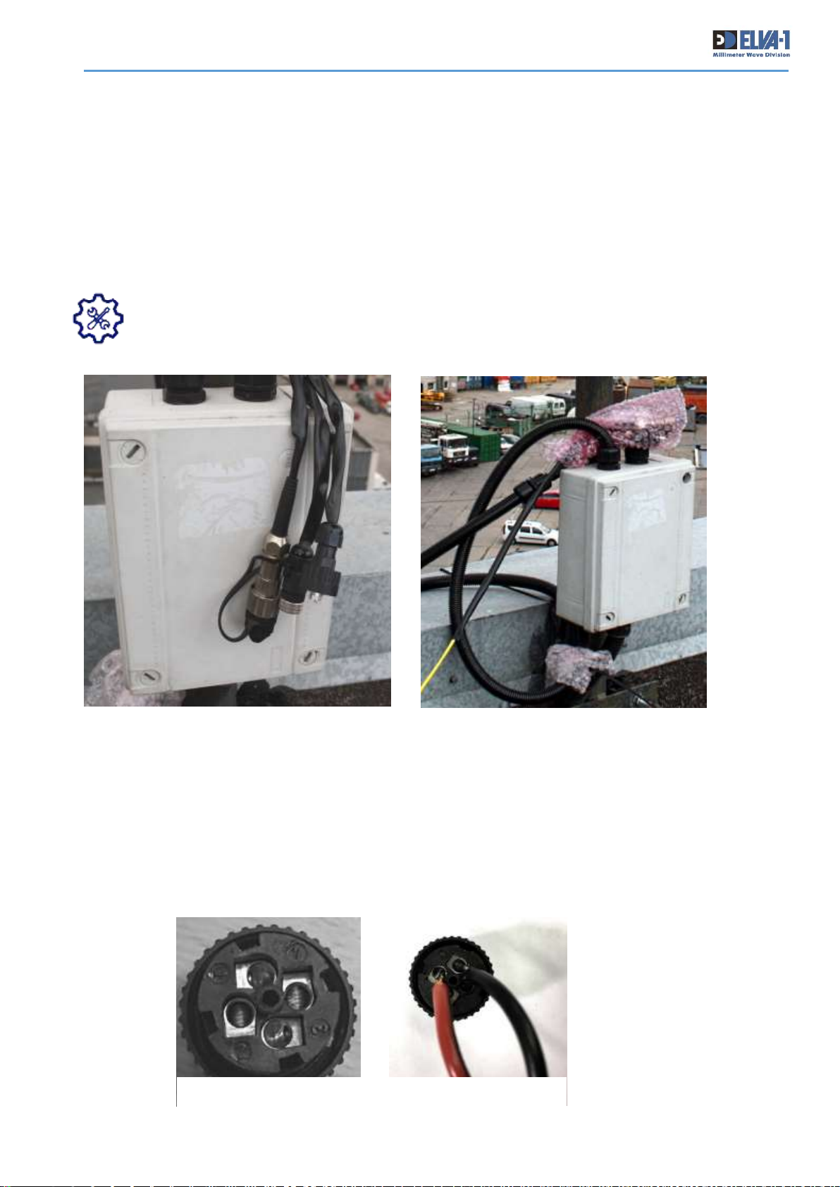
TIP. It is possible to install a cross-connection box nearby of support pipe, install all
stationary cables from indoor to this box, and then install short-length cables for power,
UTP and fiber cables from this box to the transceiver. Please mind, the cross-connection
box is not included to delivery and can be purchased locally.
Fig. 12. Cross-connection box with power, UTP and fiber cables to transceiver
• Install the power supply (PSU) in your chosen indoor location. Install 2-wire DC power cable
from PSU directly to the radio or to cross-connection box (Fig.12).
• Connect the stationary DC power cable to the PSU
• Install supplied DC connector on the side of the radio for both radio positions. Use pin #1
or #2 for “+” red wire and pin #3 or #4 for “-“ black wire. DC cable wire cross-section must be at
least 1.5 mm2 (14 AWG). The normal PSU output voltage is 54 VDC. The voltage in DC cable at
the port on the radio because of volt drop should be not less than level of 36 VDC.
Fig. 13. DC power connector pins
Page 17
PPC-10G Installation and User Manual
16
• Install a 4-pair Twisted Pair cable from Indoor network equipment directly to the radio or
to cross-connection box. Use water-proof connector from Mounting kit for last end of cable like on
Fig. 12. Be sure that the UTP cable length from last active port to radio is less than 100 m.
• Install fibre optics cable from indoor network equipment directly to the radio or to cross-
connection box. The radio is shipped with SFP+ module. Use water-proof connector from Mounting
Kit like on Fig. 12.
• Install ground wire to the position of radio installation.
• Keep end of cables with installed connectors in a plastic bag or similar cover to prevent
from dust and water before connecting them to radio transceiver sockets (see Fig.12, right photo).
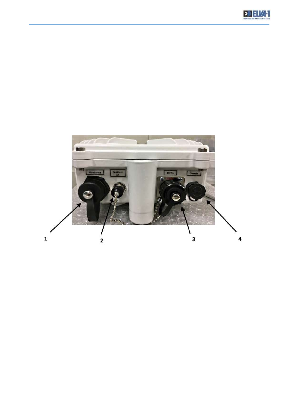
Get familiar yourself with sockets on radio case.
1. RJ-45 socket "MONITORING" for UTP cable of WEB-monitoring
2. Socket for 36-60 V DC power cable
3. SFP/SFP + "DATA" socket for 10 Gbps data transmission cable
4. “CONSOLE” socket for RSL meter unit.
Fig. 14. Transceiver sockets (#1, #2, #3, #4)
Page 18
PPC-10G Installation and User Manual
17
5. INSTALLATION OF TRANSCEIVER
• It is recommended to have 2 technicians at each site of transceiver installation with walkie-
talkie radios or mobile phones.
• Binocular also is recommended for performing easy preliminary alignment of antennas.
• Windows-based laptop with RJ-45 port is recommended at each side for easy change
between two modes of transceiver: Alignment or Operational during installation procedure (see
section 5.3 and Chapter 6 for details).
• For installation of 2+0 radio please also read Chapter 7.
5.1 RADIO ASSEMBLING AND INSTALLATION SEQUENCE
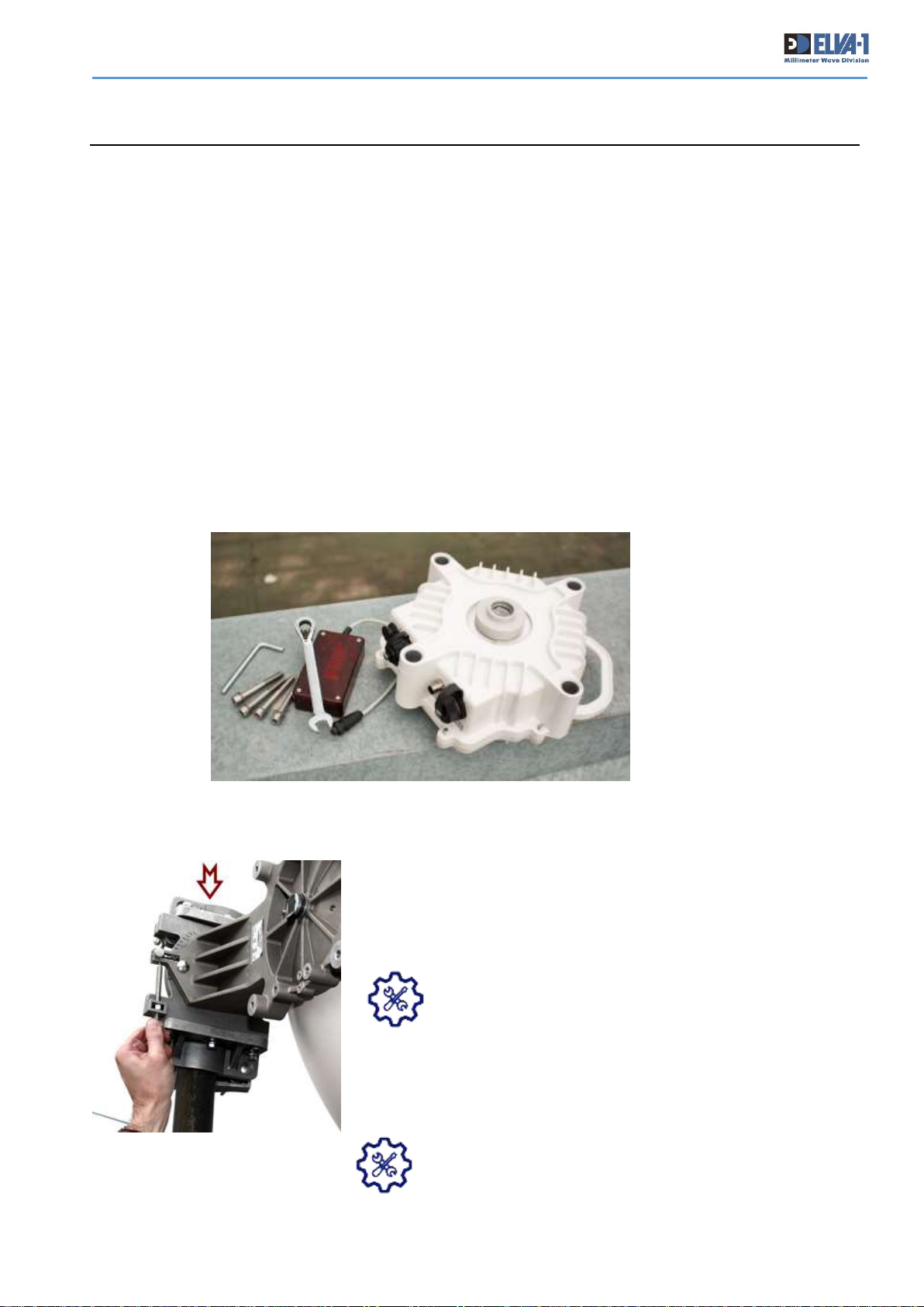
• Bring the transceiver, antenna with alignment bracket, 4 mounting screws, allen
wrench (hex key), metric open-end wrench and RSL meter to the outdoor points of
installation at both sites of the link (see photo).
For quick radio installation, the following sequence of steps is recommended:
• Make yourself familiar with the antenna alignment bracket
(mount). It allows one to change the antenna’s azimuth
(horizontal) and elevation (vertical) angles. Use the printed
manual to assemble the alignment bracket enclosed to the
package onto the antenna, if necessary.
It is recommended that the threads of all bolts be
lubricated upon assembly to protect them from
corrosion and ease removal later.
• Install antenna with alignment bracket on the support pole, and
point it to the approximate location of the opposite antenna. Use
binoculars for performing more precise preliminary alignment of
antennas.
It is possible to slide the alignment bracket over the
top of the support pole (in case of vertical pipe), then
tighten it in the appropriate position.
Fig. 15. Transceiver and tools at site of installation.
Fig. 16. It is more easy to put
the antenna on top of the pipe
than reassemble the mount to
“hug” the pipe
Page 19
PPC-10G Installation and User Manual
18
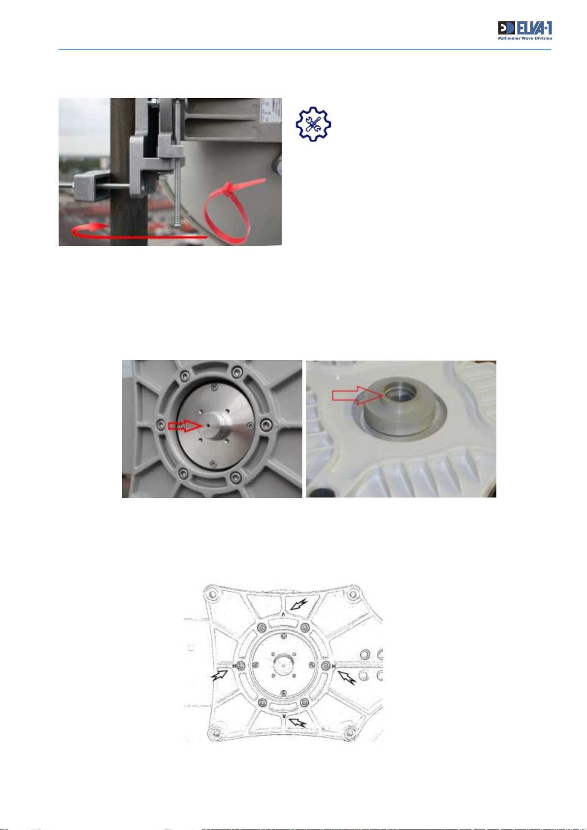
TIP. To prevent the mount with antenna
from accidentally slipping down the
vertical pipe and not getting antenna
damaged, it is recommended to use a
plastic tie strip, strongly tightening it on the pipe
stand at the desired height below projected position
of the mount. This tie strip will serve as an obstacle
to move the mount down and will not allow it to slip
below.
• Remove protective tape from each transceiver and antenna waveguide slots. See photos
below with red arrow pointing out to waveguide slots.
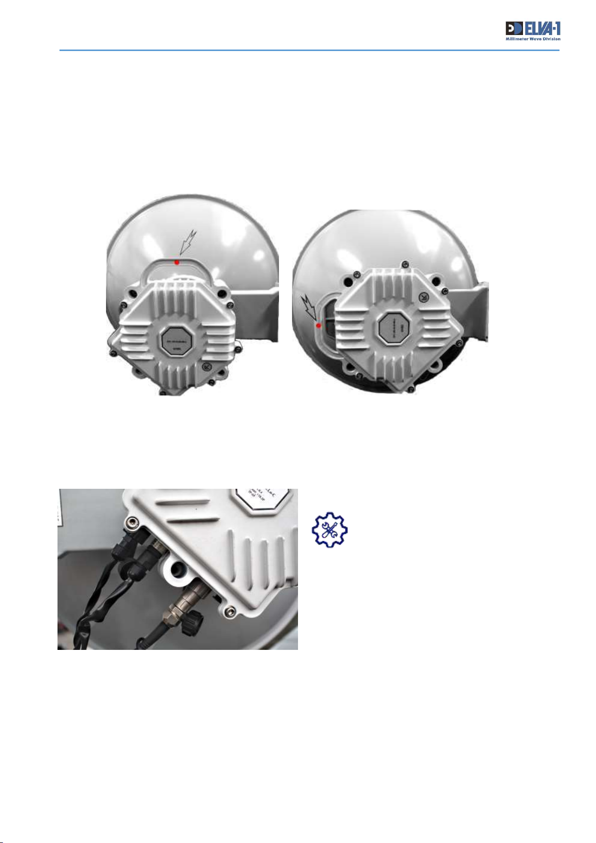
• Check “H” and “V” polarization labels on antenna. “H” means horizontal polarization and “V”
means vertical polarization. Check red label on the handle of the transceiver. This red label used
Fig. 17. A plastic tie strip tightening on the pipe stand will not allow the mount to slip down during
installation procedure and thus prevents antenna from possible damage
Fig. 18.. Remove protective tape waveguide hole on antenna and transceiver
Fig. 19. Check for “H” and “V” polarization labels on antenna
Page 20
PPC-10G Installation and User Manual
19
to comply with chosen polarization. Red label has to be on top of mounted transceiver for vertical
polarization and left or right side for horizontal polarization.
• When mounting transceiver to the antenna, choose “V” vertical polarization by default on
both radios. In case of installing two parallel PPC-10G links from the same position, use vertical
polarization on first link, and horizontal polarization on other link.
• Mount each transceiver to its antenna with 4 mounting screws. Be sure that socket of radio
are directed down, and not up. This is to get rain drops fall down from radio sockets easily.
TIP. Always be sure that socket of
radio are directed down, and not up.
Fig. 20. Photo of V-polarization (left) and H-polarization (right) red label
Fig. 21. Position of sockets to be directed
down, not up
Page 21
PPC-10G Installation and User Manual
20
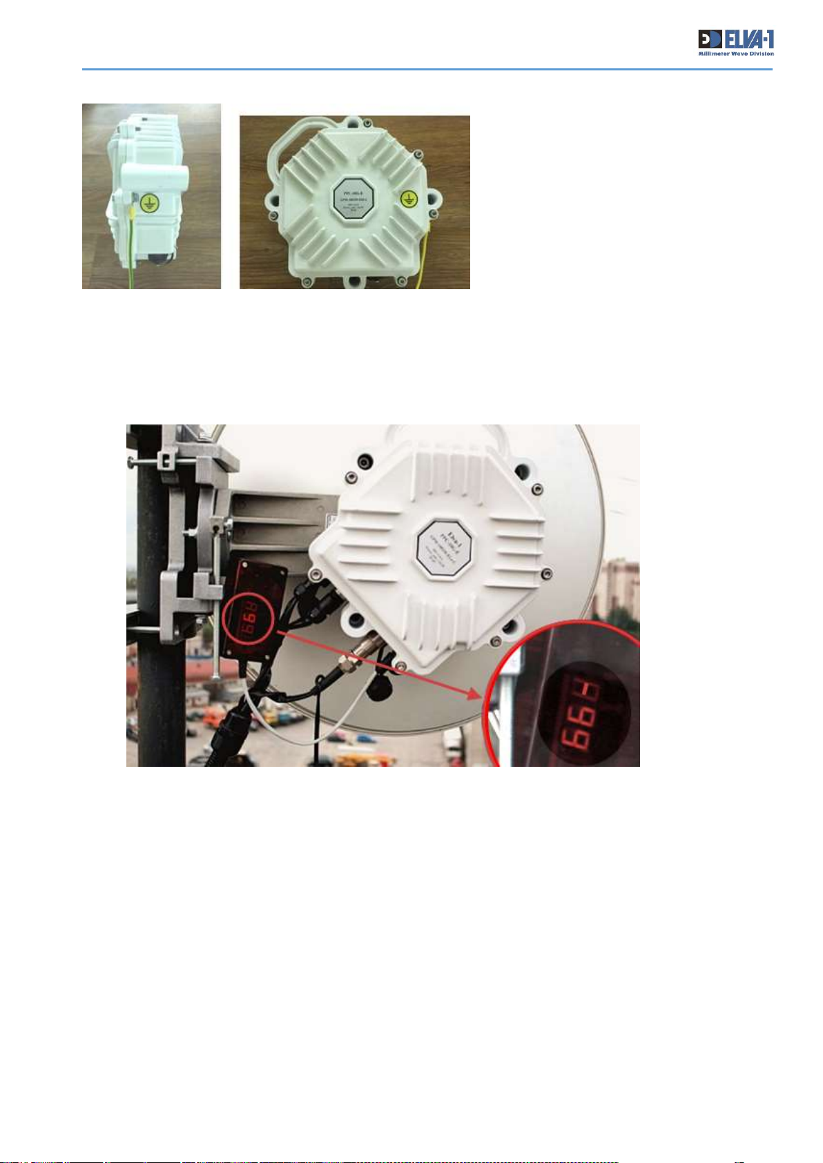
• Install grounding wire to the bolt
nearby of the GROUND label as on
photo.
• Insert all connectors of power cable, UTP and Fiber optics cables into relevant sockets on
transceiver marked as DC, MONITORING, DATA respectively. Insert RSL meter (aka attenuation
meter) connector into CONSOLE socket on transceiver.
• Ask personnel at the indoor location to switch the 54 VDC power ON.
• Check if RSL meter is on. By default, it indicates “-99.9”.
Fig. 22. Grounding wire position
Fig. 23. RSL meter indicates -99.9 if the antenna is not aligned to opposite one
Page 22

PPC-10G Installation and User Manual
21
5.2 FINAL ANTENNA ALIGNMENT
For maximum throughput, the antennas must be aligned directly on the LOS. Please consider that
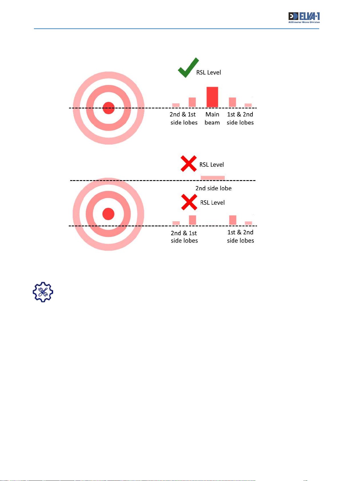
antenna radiation pattern has main beam (central beam) and side lobes. The task is to aligned
both antennas onto main beam, not side lobes (as throughput and operation distance at side lobes
are low and unstable).
Use the following procedures to accomplish this final alignment:
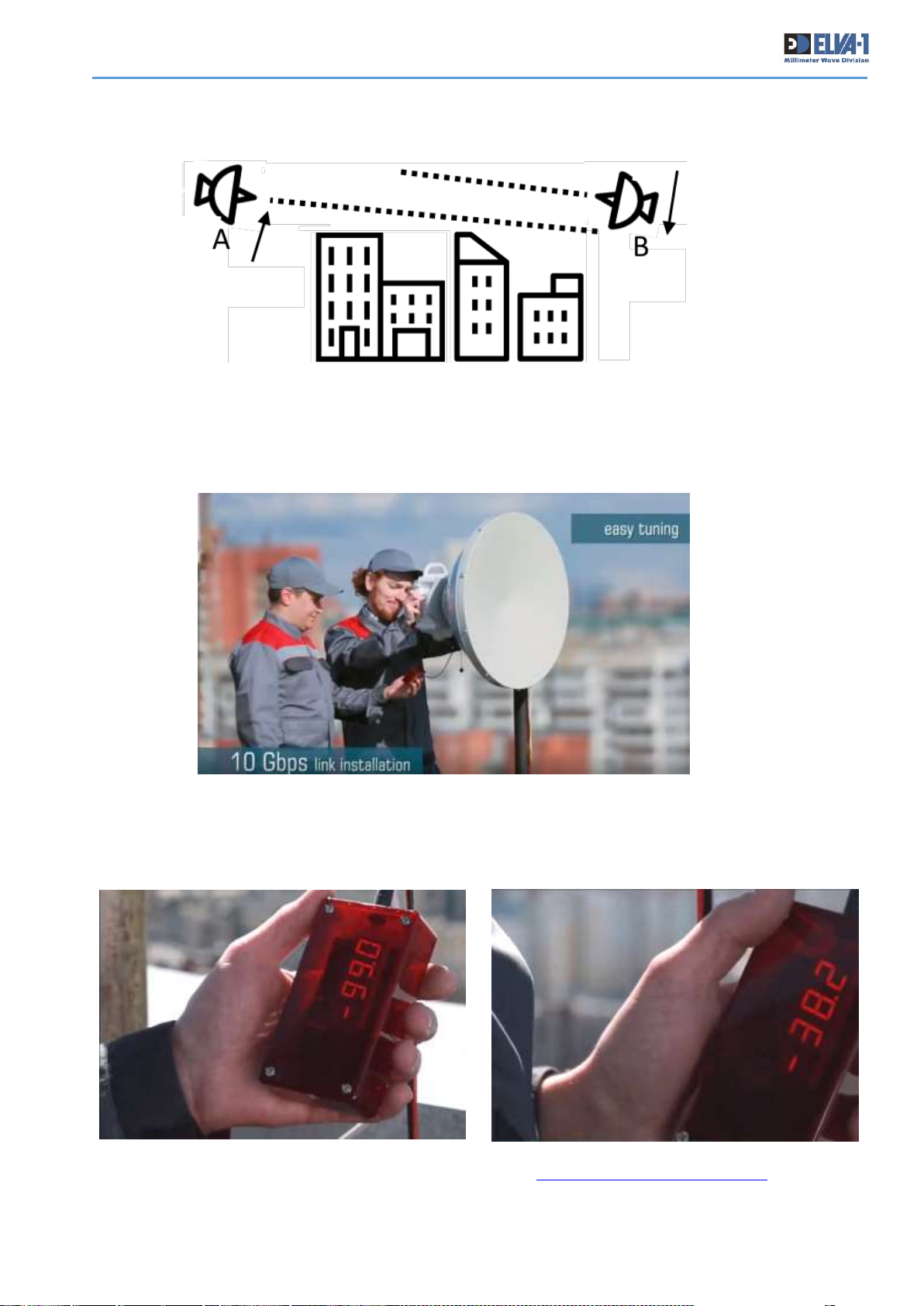
a. Place a technician with instructions on how to adjust antenna horizontal and vertical
movement at each radio location, and designate the antenna at one location as A and the one at
the other location as B. The technicians should have cell phone or other mobile communication
availability to coordinate their antenna adjustments. Ideally, one person should also be in place
at each radio’s indoor power supply, with a means of communication to receive instructions to turn
the power supply ON or OFF.
b. Using the vertical adjustment bolt on the radio mount, adjust Antenna A to an alignment
that is noticeably below the LOS.
Fig. 24. Antenna radiation pattern has central beam and side lobes
Fig. 25. The technicians should coordinate their antenna adjustments on both sides of the link
Page 23
PPC-10G Installation and User Manual
22
c. Using the same adjustment, adjust Antenna B to an alignment that is noticeably above the
LOS.
d. Turn power ON for both radios by turning on their indoor power supplies, and confirm that
an RSL meter is connected to the CONSOLE socket of each radio and turned ON (initial meter
reading should be -99.9),
Fig. 26. Antennas A and B to an alignment that is above (B) and below (A) the LOS.
Fig. 27. Check RSL meter indication when running alignment procedure
Fig. 28. During antenna alignment, RSL indication should change from -99 to actual “RSL at alignment mode’
value for your distance according Link Budget Calculator (see
http://linkbudgetcalc.elva-1.com )
Page 24
PPC-10G Installation and User Manual
23
TIP. When make final antenna alignment, consider antenna radiation pattern has main
beam (central beam) and side lobes as illustrated on Fig. 24, 29.
e. Using the vertical adjustment bolts, simultaneously move Antenna A up and Antenna B
down in steps equivalent to one quarter-turn on their adjustment bolts. After each step, use the
horizontal adjustment bolts to sweep Antenna A and Antenna B about 10° right and 10° left of the
visual LOS center line. If a signal is noticed (a increase in the number on the RSL meters), stop
the adjustment where the RSL meter number is highest. If no signal is detected, repeat Step “e”
until the number increases on the RSL meter.
f. Adjust Antenna A horizontally and vertically to obtain the highest RSL meter number. See
Fig.29 to understand how many RSL meter peaks could be seen on RSL meter.
g. After the initial signal acquisition, and best horizontal and vertical alignment (highest RSL
meter number) on Antenna A, adjust Antenna B horizontally and vertically to obtain the highest
RSL meter number for Antenna B.
h. Repeat Steps “f” and “g” to obtain the highest RSL meter numbers on both Antenna A and
Antenna B.
i. At this point the expected RSL number should be displayed on both attenuation meters. If
it is, lock both antennas in their final positions.
Fig. 29. Diagram for relevance of RSL meter indication to antenna side lobes
Page 25
PPC-10G Installation and User Manual
24
j. It is acceptable for the number displayed on the RSL meter to be as much as two points
lower than the expected value. For example, if your expected RSL number is -45.0, but your RSL
meter(s) displays -47.0 and you cannot achieve higher number of RSL, this is considered to be
within normal tolerance.
k. Disconnect the RSL meters and cover the CONSOLE socket with the attached rubber cap.
Confirm that all alignment bracket bolts are strongly secured in place. The outdoor link hardware
is now ready for operation.
l. Check that all indoor connectors for UTP cable (MONITORING) and fiber optics cable (DATA)
are plugged into relevant sockets of indoor network equipment such as a 10 Gigabit Ethernet
Switch.
m. Flow Control (IEEE 802.3X) mode on 10 Gigabit Ethernet Switch must be enabled.
It is also required to switch the link from factory predefined Alignment mode to
Operational mode (read Section 5.3 and Chapter 6) to get the link ready for operation.
5.3 UNDERSTANDING OF ALIGNMENT AND OPERATIONAL MODES OF TRANSCEIVER
All PPC-10G link modifications have adaptive to weather modulation feature implemented for better
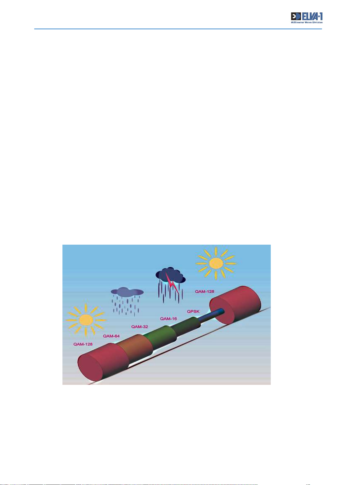
wireless channel availability. The PPC-10G link has two modes for signal transmitting, factory
predefined Alignment mode and user defined Operational mode. At Alignment mode, link’s adaptive
modulation is OFF to help for antenna alignment procedure. At Operational mode link’s adaptive
modulation is ON. So, after the alignment procedure is complete, it is required to switch the link
from factory predefined Alignment mode to Operational mode for normal operation of PPC-10G.
During good weather conditions when the link’s SNR (Signal to Noise Ratio) is high, operation at
full capacity is enabled, reaching the maximum speed of 10Gbps. In case that the link`s SNR drops
significantly (during heavy rain), the channel throughput will be reduced to keep the wireless
channel connectivity alive.
Fig. 30. Wireless channel throughput at different weather conditions for 70/80 GHz
band when using adaptive modulation
Page 26

PPC-10G Installation and User Manual
25
6. USING WEB INTERFACE FOR FIRST-TIME LINK SETUP
6.1 UNDERSTANDING WEB INTERFACE CONNECTION TO RADIOS
When PPC-10G transceivers are installed on both sides of the link, and cables from both radios are
connected to LAN switch at each side of the link, PPC-10G radios can be accessed over LAN using
the Web Interface by link’s IP addresses (radios are GUI-enabled).
Any available web browser may be used, but Google Chrome is recommended. Desktop PCs,
notebooks, tablets and smartphones are supported to get admin access to PPC-10G radios for
either Windows, macOS/iOS and Android operating systems.
By factory default, each transceiver has IP address for Web Interface access. These IP addresses
are different – the transceiver named Hi has internal IP address 192.168.127.254, while Lo -
192.168.127.253.
What are Hi or Lo symbols mean? One radio of the link works
in the higher part of the allocated frequency band and is called
Hi, while another radio works in lower band and called Lo.
There is label on the back of radio body with Hi or Lo symbols
in the link abbreviation (see illustration below). To review
which radio is Hi and which one is Lo, check label on the radio’s
body.
Fig. 31. PPC-10G radios LAN / WAN web access connectivity – over LAN at each side or over the Internet
Fig. 32. Example of PPC-10G label with Hi symbols on the back of the radio body
Page 27
PPC-10G Installation and User Manual
26
The system administrator (aka Admin) could connect to each radio by its IP address in 3 ways:
1. Connect from Admin PC (PC, notebook or mobile device) to the radio while are in the same
LAN segment as this radio.
2. Connect from Admin PC (PC, notebook or mobile device) to the radio over WAN (over the
Internet). In this case Hi and Lo radios have to have static IP addresses accessed globally.
Otherwise, Virtual Desktop technology could also be used for remote connection from Internet to
a computer inside LAN, then running web browser on this computer and do all works as within
LAN.
3. Directly connect from Admin PC (notebook with Ethernet port) to the radio by UTP cable
from indoor (by a stationary UTP cable) or outdoor (by a temporary UTP cable). This way usually
used only in some situations of initial installation of the link or at link repair works.
For way #3, can use UTP cable with RJ-45 connector that come from radio to indoor
switch, just unplug it from switch and connect it to your notebook. You can also connect
notebook to #1 MONITORING socket on the radio directly at place of installation (roof,
tower, etc), using temporary twisted pair cable with RJ-45 connectors if needed (be sure
radio’s external Power Supply is ON to get access). Remember, default IP addresses are
192.168.127.254 for Hi radio, while Lo - 192.168.127.253.
6.2 FIRST TIME CONNECTION TO RADIOS AT BOTH SIDES OF THE LINK
Please mind, until you switched both radios from Alignment mode to Operational mode using Web
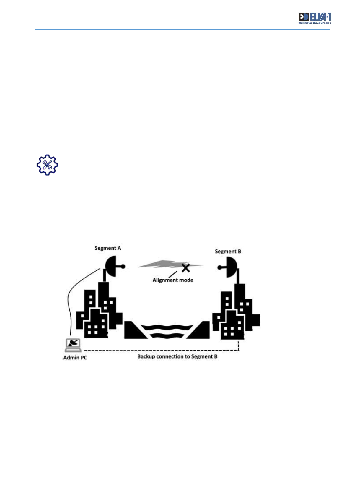
Interface, there will be NO wireless connection between radios in network segments A and B (see
Fig.33). This means that Admin can get access to the radio on remote site only if there is any
backup connection to LAN segment at remote site.
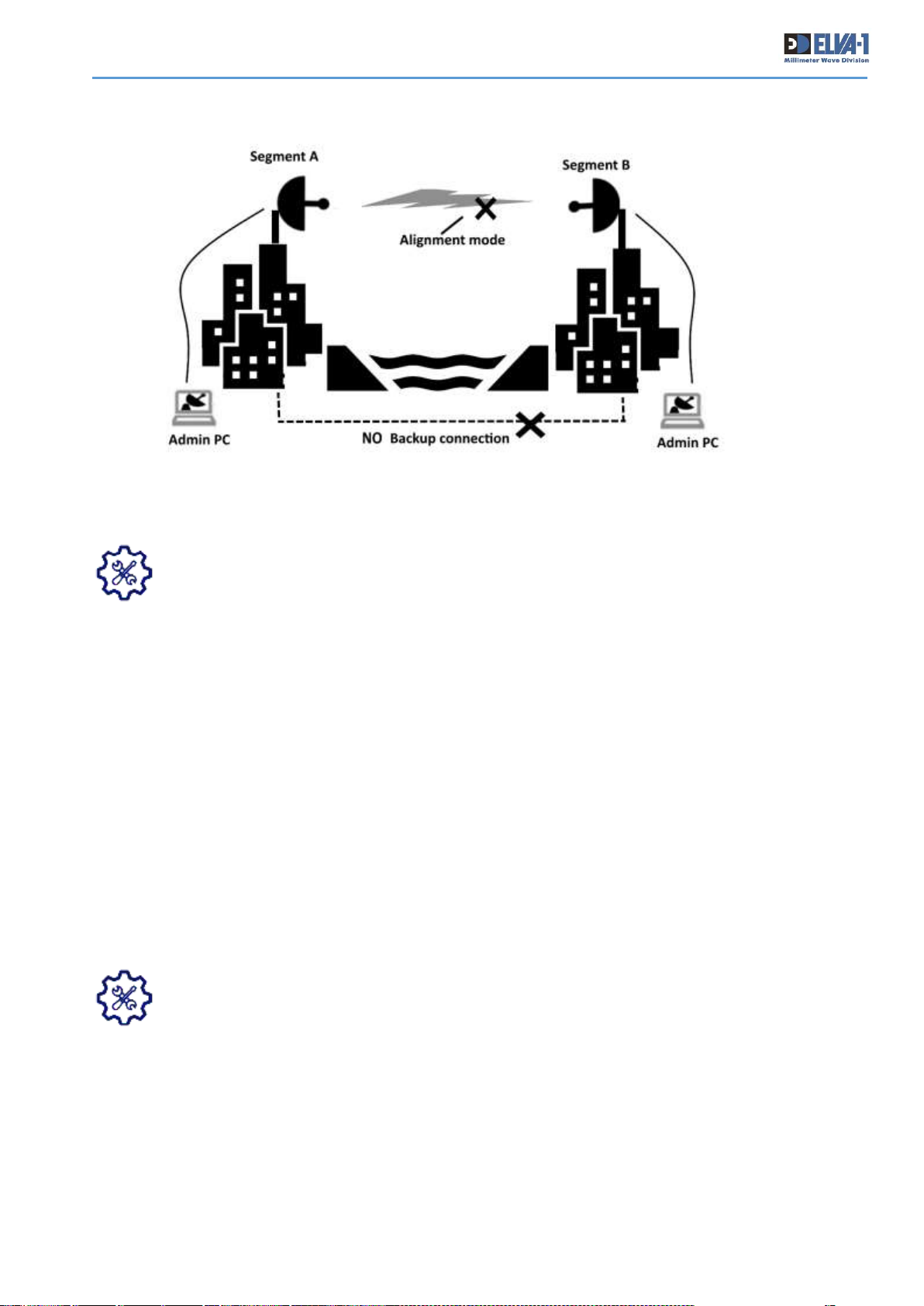
Otherwise, Admin required to personally come to the site of Segment B and connect to those radio
at Segment B locally (Fig.34). This is “first time login” situation only. Later, with switched both
radios into Operational mode and wireless connection between radios will be active, it is possible
to connect to any radio from any point of LAN or WAN (including over the Internet).
Fig. 33. Case of admin connection to both radios with backup channel
Page 28
PPC-10G Installation and User Manual
27
Be sure 192.168.127.254, 192.168.127.253 addresses are not occupied in your network
by any other devices before first-time connection to radios by web interface. Otherwise,
release these IP addresses temporary for the “first time login” to radios. In case if
releasing of addresses is not possible, bring Admin notebook equipped with Ethernet
RJ-45 port to nearby of LAN switch with MONITORING cable coming from the radio. Disconnect
MONITORING cable from the switch and insert this cable RJ-45 jack into notebook’s Ethernet port.
Start web browser on the notebook and proceed as described below.
6.3 LOGIN TO RADIOS AND INITIAL SETUP
To connect to radio Hi and Lo by its IP address, enter it in browser’s address line. Any available
web browser may be used, but Google Chrome is recommended.
The factory default PPC-10G IP addresses are:
Hi Radio - 192.168.127.254, Lo radio – 192.168.127.253.
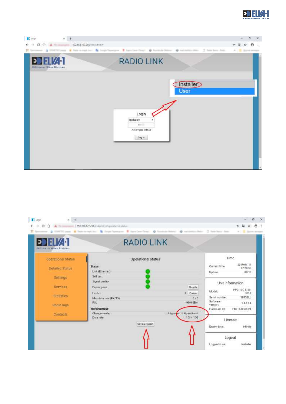
When you arrive at the web page, proceed as follows (Fig.35):
• Choose Installer from drop-down menu as the Access Level
• Enter the default password: 111111
Installer is an Admin level access, and has rights to change parameters.
User is a reader level access, and has rights to only view parameters.
Please mind Auto-Logout because on Web Interface inactivity after 10 min.
Fig. 34. Case of admin connection to each radio while there is NO backup channel
Page 29
PPC-10G Installation and User Manual
28
• When enter to the radio Web Interface page (Fig.33), press the Operational radio button
in the window. Then press the Save and Reboot button and wait until the transceiver restarts.
The normal wireless data transmission mode is now activated, but only for this radio – to fully
activate main data channel, you need to repeat this procedure for second transceiver as well.
Fig. 36. Press the Operational radio button
Fig. 35. Login as Installer with default password 111111
Page 30
PPC-10G Installation and User Manual
29
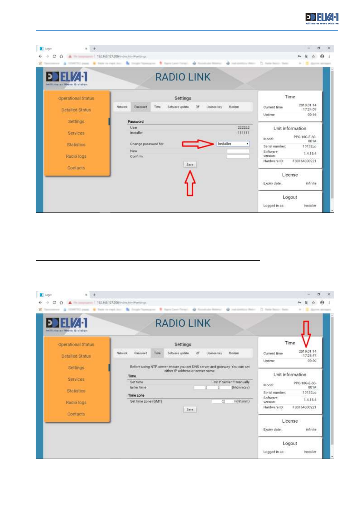
• Change password for Web Interface access to this radio (Fig.37). For this, choose
Settings on left menu, then Password tab at top. Enter new password, retype it, then click
Save and Reboot button. Use only Latin characters and digits, 6 - 20 symbols long.
It is possible to change password for both Installer and User roles here.
• Save new password in a protected local file or cloud storage, otherwise just write down on
the paper book. Don’t forget to mark this password is valid for Hi or Lo radio.
Fig. 37.Change password for Web Interface access to this radio
Fig. 38. Check and if necessary adjust actual time settings for the radio
Page 31
PPC-10G Installation and User Manual
30
• Set the time for radio to actual local time. You can set time manually or from NTP Server
(NTP server requires setting DNS and Gateway at IP Settings tab). By default, “UTC 0” time zone
is used. For this, choose Settings on left menu, then Time tab at top. Adjust hours and minutes
to local time, then click Save button (Fig.38).
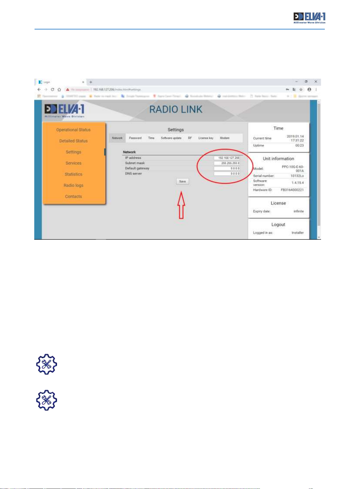
• Change IP address of this radio from default to actual one. For this, choose Settings on
left menu and Network tab at top (Fig.39). Enter the IP parameters of your choice (could use
default Mask 255.255.255.0 and default Gateway 0.0.0.0). Click Save button.
• Save new IP address in the protected file or cloud storage, otherwise just write down on
the paper. Don’t forget to mark this address valid for Hi or Lo radio.
After you entered new IP address, this Web Interface session will be finished with “Not found”
page. To login to the radio next time, use new actual IP address in the browser address bar and
new actual password.
TIP. If you have backup network connection to LAN segment where another radio is
installed (Fig.33), repeat right now all steps you did in this section, login to and setup
another radio. Otherwise come to another LAN segment (Fig. 34) or delegate this task
to another admin and repeat all steps there. The main data channel will be automatically
ON when both radios will be switched into Operational mode.
In case of forgotten password please contact your supplier’s technical support. They will
restore factory default password, so you can change it to actual one again. Letter of
Authorization may be required from your CEO or CIO to confirm this request for password
recovery.
From now, the initial PPC-10G setup is complete. To get familiar with all Web Interface menus and
tabs, proceed to another document, called Web Interface Manual.
Fig. 39. Change IP address of the radio from default to actual one
Page 32
PPC-10G Installation and User Manual
31
7. 2+0 LINK ASSEMBLING, INSTALLING AND SETUP
7.1 PPC-10G 2+0 UNPACKING
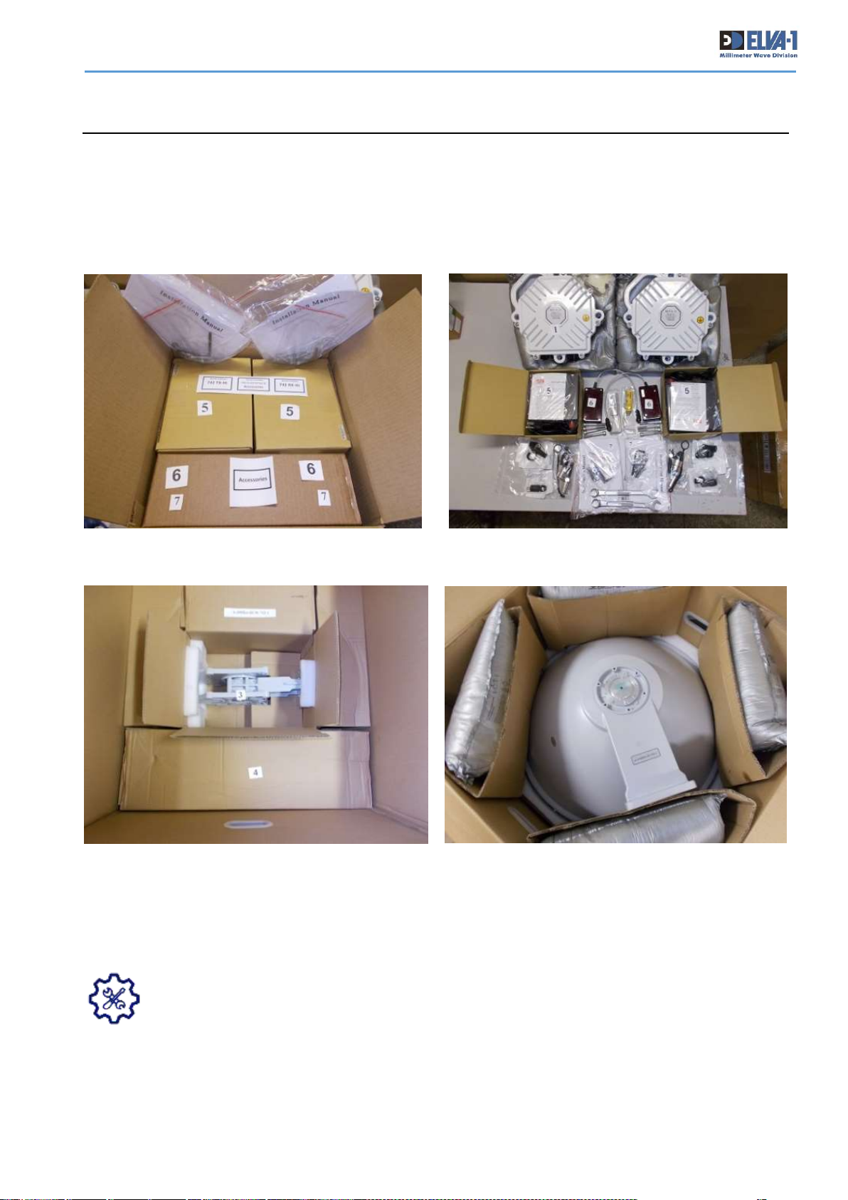
PPC-10G 2+0 equipment will arrive in 4 boxes. The first two boxes contain transceivers of the
upper and low frequency ranges and accessories (cables, connectors, tools, etc.). The each box
contains 3 smaller boxes inside with transceivers and one small box with doubled Mounting Kit of
power units, cables, sockets, tools, RSL meter.
As for other PPC-10G link modification, it is recommended to store packaging materials for
12 month of link warranty.
For list of components in delivery package see Table 1 and Table 2.
For information on transceiver sockets and connectors see Fig.11 – Fig.14.
Fig. 40. 2+0 package with transceivers and accessories
Fig. 41. 2+0 package with antenna and dual polarization adapter
Page 33
PPC-10G Installation and User Manual
32
7.2 ASSEMBLING AND INSTALLATION OF 2+0 LINK
Mind 2+0 link is a combination of two independed transceivers which share the same
antenna. It is strongly recommended to read Chapters 5 and 6 of this Manual before
starting any works on installation of PPC-10G 2+0 link.
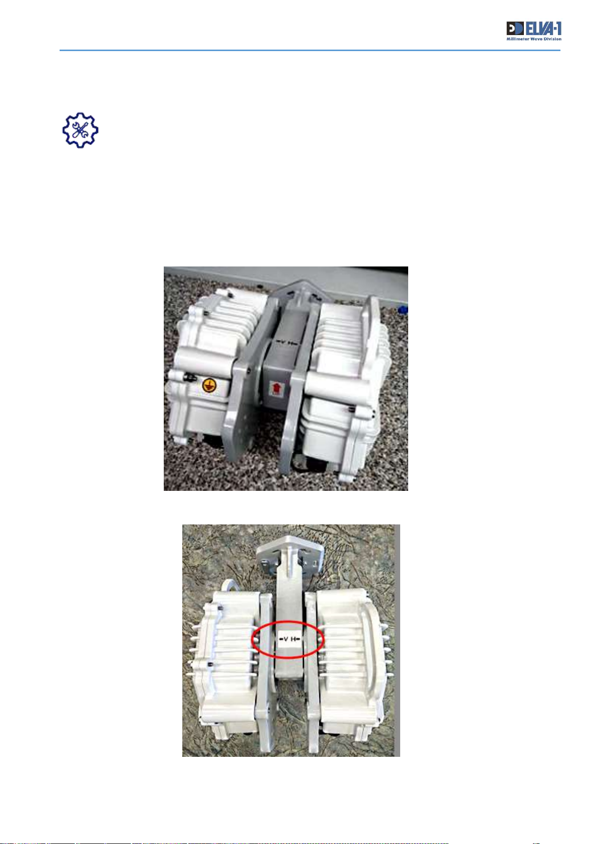
• Get yourself familiar with all parts in 2+0 delivery. Assemble transmitter and receiver with
diplexer (dual polarisation adapter, DPA). Use 4 mounting screws and hex key. Attach the blocks
so that the sockets on transceivers are pointing down. Look at arrow "UP" label like on Fig.42.
• Make two such assemblies. Be careful when assembling transceivers to dual polarisation
adapter, it is necessary to observe polarization. Look at “<-V H->” label like on Fig.43.
Fig. 42. Two transceivers assembled with dual polarisation adapter
Fig. 43. Mind polarisation label on DPA
Page 34
PPC-10G Installation and User Manual
33
• Install doubled number of stationary cables (see. Section 4.6) as 2x power cables, 2x UTP
and 2x fiber optics cables at each side of the link.
• Install antenna with mount on the supporting pipe as described in Chapter 5 and point it to
the approximate location of the opposite antenna. Use binoculars for performing more precise
preliminary alignment of antennas.
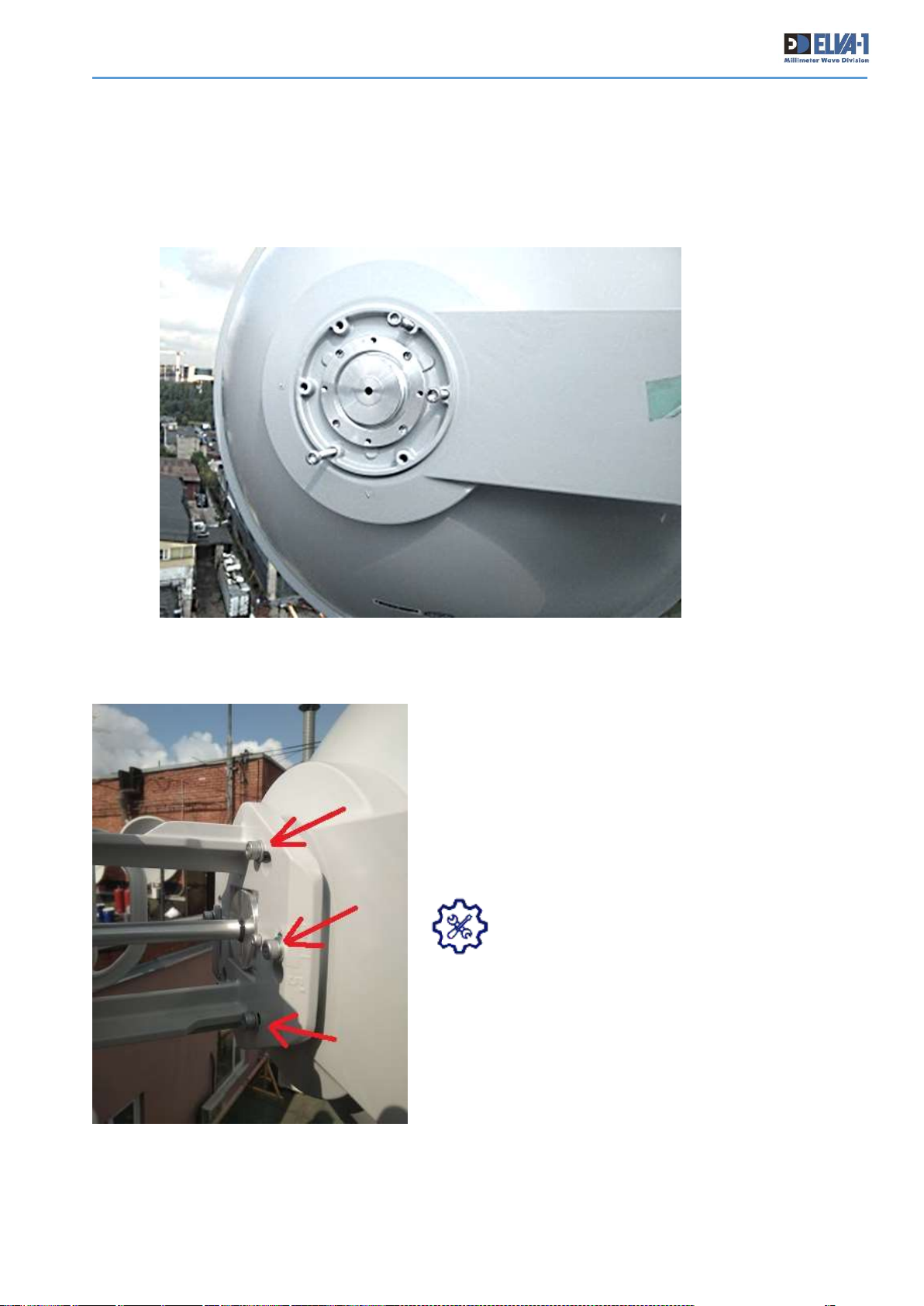
• Install 3 bolts on positions of “5, 15 and 35
minutes” on the antenna flange (Fig. 44). Do not screw
them strongly into antenna flange. These bolts will serve
like hooks for diplexer.
• Put on the diplexer with pre-screwed two
transceivers on 3 bolts like on hooks and rotate to
prevent diplexer from fall down.
• Install other 3 bolts with washers on
positions “25, 45 and 55 minutes” on the
antenna flange. Now there are all 6 bolts with
washerы on place.
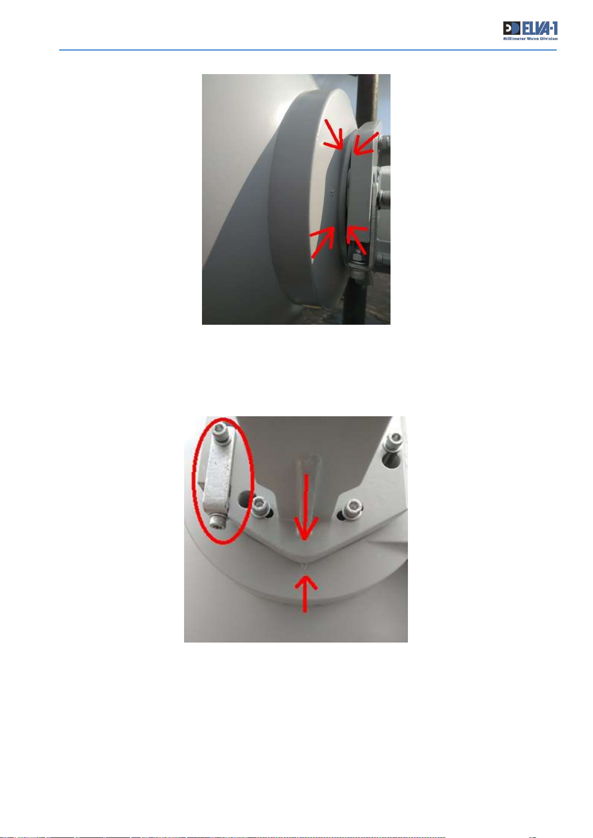
Do not allow the appearance of an uneven gap between
the antenna and the diplexer.
Fig. 44. Install 3 bolts on positions of “5, 15 and 35 minutes“ on the antenna flange
Fig. 45. Use 6 bolts to screw diplexer to antenna flange
Page 35
PPC-10G Installation and User Manual
34
The diplexer must be connected to the antenna without twisting. See the marks in the photo
Fig.47 (are indicated with arrows.). If required, adjust the diplexer rotation using the element
marked by red oval.
Strongly tighten all 6x mounting bolts between antenna and diplexer.
Fig. 46. Do not allow the appearance of an uneven gap between the antenna and the diplexer
Fig. 47. Adjust the diplexer rotation using the element marked by red oval
Page 36

PPC-10G Installation and User Manual
35
7.3 ANTENNA ALIGNMENT FOR 2+0 LINK
• Insert all cables to both transceivers at both sides of the link, switch the power ON for all
four transceivers.
• Insert RSL meter to transceiver with vertical (V) polarisation at both sides of the link.
• Proceed antenna alignment like in Section 5.2.
• Disconnect the RSL meter from “V” transceiver at both sides of the link and cover the
CONSOLE socket with the attached rubber caps.
• Insert RSL meter to transceiver with horizontal (H) polarisation at both sides of the link.
Check RSL meter indication. It should be about the same as RSL meter indication for “V”
transceiver that seen before. If it is not, check the bolts and marks for rotation of the diplexer
relatively to antenna flange.
• Disconnect the RSL meter from “H” transceiver at both sides of the link and cover the
CONSOLE socket with the attached rubber caps.
The installation and alignment procedure is now complete.
7.4 LOGIN TO 2+0 RADIOS AND INITIAL SETUP
Mind 2+0 link as a combination of two 1+0 links which just share the same antenna, so run IP
setup for each pair of transceivers (pair in “V” polarisation and pair in “H” polarisation)
independently.
Use the following IP addresses:
Hi Radio #1 - 192.168.127.254,
Lo Radio #1 – 192.168.127.253
Hi Radio #2 - 192.168.127.254,
Lo Radio #2 – 192.168.127.253.
• Login to first pair of radios (does not matter - pair in “V” polarisation or pair in “H”
polarisation) and run initial setup as described in Section 6.3.
• Release 192.168.127.254, 192.168.127.253 to make them not occupied for setup of
second pair of radios, and repeat setup procedure as described in Section 6.3 for second pair of
radios.
Page 37

PPC-10G Installation and User Manual
36
8. MAINTENANCE AND TROUBLESHOOTING
PPC-10G has been designed to require practically zero periodic maintenance. However, each radio
of the link should be periodically inspected for visible damage or excessive accumulation of dirt.
Use a brush or sponge with water to clean antenna and transceiver. When run cleaning procedure,
do not stand in front of the energized antenna if transceiver power is ON.
In case of a complete or partial communication failure, please perform the following checklist:
1. Make a visual inspection of the radios for mechanical integrity of and between the transceiver
and antenna, and check to be sure that the cable joints are reliable and no unauthorized objects
are on the antennas. Remove dust or snow from antennas if necessary.
2. Check the signal propagation line (LOS) to be sure that no obstacles like buildings, cranes,
electric lines, trees have appeared in it or its vicinity. If necessary, remove the obstacle or change
the radio position.
3. Make sure of that the radio is receiving power from the power supply:
• Measure voltage at radio end of power cable while PSU is on.
• The power supply voltage should be between 36 and 60 VDC. If it is not, clear the fault
of the power supply source or use a thicker gauge wire for a smaller voltage drop.
4. Make sure of that the UTP and optical cables are transporting data to/from the radios.
5. Connect RSL meter, and check the value. The RSL should correspond to the value given in the
calculation for actual distance. If it does not, find and correct the cause.
Possible causes of low RSL reading:
• Precipitation along the signal propagation line. Wait until the clear weather and repeat the
measurements.
• Obstacles on the signal propagation line. Remove them or change the position of the
radio.
• Alignment disturbance (could happen occasionally after very strong wind or because of
ice buildup during winter). Re-align the antennas.
• Transceiver failure.
If the radio still does not operate properly, measure and write down RSL, make WEB screenshots
and copy last log files, then contact your supplier.
ELVA-1 Service Center email:
Page 38
PPC-10G Installation and User Manual
37
9. APPENDIX A
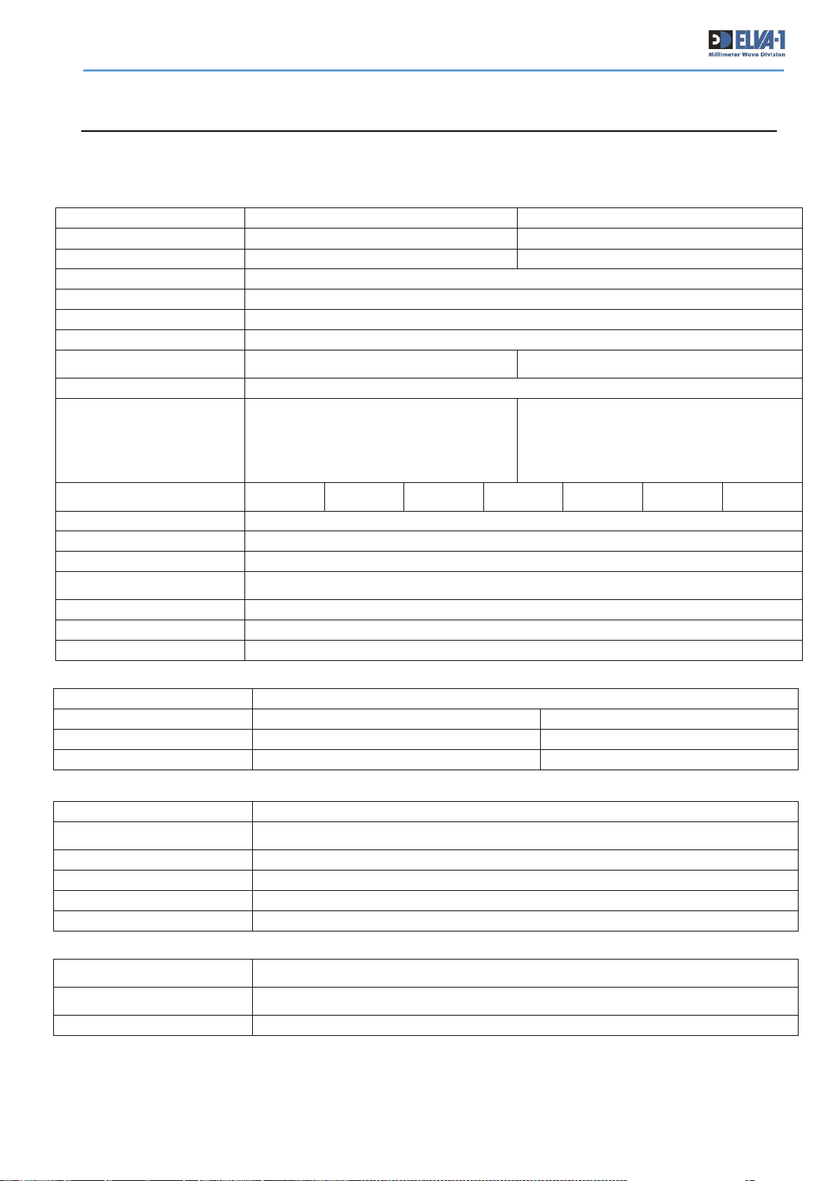
9.1 PPC-10G SPECIFICATIONS
Antenna
Antenna Type
Cassegrain type antenna with radio-transparent radome
Antenna Gain/Beamwidth
71-76/81-86 GHz (E-band)
40.5-43.5 GHz (Q-band)
- 1ft antenna
45 dB/0.7°
38 dB/1.5°
- 2ft antenna
51 dB/0.35°
44 dB/0.70
Power / Environment
Power Supply AC
Input 88-132 / 176-264 Volts, 50/60 Hz
Transceiver Power Consumption
(for one radio)
45 W (+60 W when heater is switched on)
DC Power
36 to 60 Volts DC
Power Connection
IP-67
Operational Temperature
-500C to +600C / -580F to 1400F
Humidity
Up to 100%
Physical dimensions
Outdoor unit size
w/o antenna
246 х 246 х 110mm
Weight
(ODU w/o antenna)
4 kg max
Complete set
2 radios with antennas + 2 indoor power supplies
Model
PPC-10G-E
PPC-10G-Q
Frequency range
71-76/81-86 GHz (E-band)
40.5-43.5 GHz (Q-band)
Throughput
Up to 10 Gbps Full duplex
Up to 7.2 Gbps Full duplex
Channel Bandwidths Available
250/ 500/ 750 / 1000 / 1250 / @E-band 1500 / 2000 MHz
Modulation
QAM-256 to BPSK Adaptive to weather with hitless adaptive bandwidth, coding and modulation
MTBF
150 000 hours
Central frequency
Tunable 71-76GHz for Hi ODU, 81-86GHz for Low ODU at 125 MHz /31.25 MHz steps
Max Distance at
max throughput
up to 20.0 km (12.4 miles)
with 2ft antennas at clear sky
up to 20.0 km (12.4 miles)
with 2ft antennas at clear sky
Max output power
17 dBm (50 mW) at QAM 128 / 20 dBm (100 mW) at QPSK/BPSK
Link budget
with 2ft antennas
BPSK/QPSK modulation
@ 10-9 BER
200 / 197dB @250MHz
197 / 194dB @500MHz
195 / 192dB @750MHz
194 / 191dB @1000MHz
193 / 190dB @1250MHz
192 / 189dB @1500MHz
191 / 188dB @2000MHz
186 / 183dB @250MHz
183 / 180dB @500MHz
181 / 178dB @750MHz
180 / 177dB @1000MHz
179 / 176dB @1250MHz
Max throughput
1330Mbps
@250MHz
2660Mbps
@500MHz
3750Mbps
@750MHz
5200Mbps
@1000MHz
7200Mbps
@1250MHz
7630Mbps
@1500MHz
9980Mbps
@2000MHz
Management
SNMP v.1; v.2; MIB-II and proprietary MIB; WEB GUI; Telnet; CLI
Ethernet Interface
1 × SFP/SFP+ slot (1000Base-X, 10GBase-LR/SR)
Encryption
AES 128 Optionally
Ethernet
Transparent for Ethernet services, Flow Control 802.3x
PTP IEEE 1588v2 (TC) support
Management Port
100 Base-Tx (RJ – 45)
Forward Error Correction
LDPC; Reed Solomon
Polarization
Vertical / Horizontal
Page 39
PPC-10G Installation and User Manual
38
9.2 PPC-10G-HP SPECIFICATIONS
Antenna
Antenna Type
Cassegrain type antenna with radio-transparent radome
Antenna Gain/Beamwidth
71-76/81-86 GHz (E-band)
40.5-43.5 GHz (Q-band)
- 1ft antenna
45 dB/0.7°
38 dB/1.5°
- 2ft antenna
51 dB/0.35°
44 dB/0.70
Power / Environment
Power Supply AC
Input 88-132 / 176-264 Volts, 50/60 Hz
Transceiver Power
Consumption (for one radio)
45 W (+60 W when heater is switched ON)
DC Power
36 to 60 Volts DC
Power Connection
IP-67
Operational Temperature
-500C to +600C / -580F to 1400F
Humidity
Up to 100%
Physical dimensions
Outdoor unit size
w/o antenna
246 х 246 х 110mm
Weight
(ODU w/o antenna)
4 kg max
Delivery set
2 radios with antennas + 2 indoor power supplies
Model
PPC-10G-E-HP
PPC-10G-Q-HP
Frequency range
71-76/81-86 GHz (E-band)
40.5-43.5 GHz (Q-band)
Throughput
Up to 10 Gbps Full duplex
Channel Bandwidths
Available
250/ 500/ 750 /1000 /1250 /1500 /2000 MHz
Modulation
QAM-256 to BPSK Adaptive to weather with hitless adaptive bandwidth, coding and modulation
MTBF
150 000 hours
Max distance at
max throughput
up to 24.0 km (15 miles) at clear sky with 2ft antennas
Max output power
24.7 dBm (295 mW) at QPSK/BPSK
Link budget
with 2ft antennas,
BPSK modulation
@ 10-9 BER
208 dB @250 MHz
205 dB @500 MHz
203 dB @750 MHz
202 dB @1000 MHz
201 dB @1250 MHz
200 dB @1500 MHz
199 dB @2000 MHz
190 dB @250 MHz
187 dB @500 MHz
185 dB @750 MHz
184 dB @1000 MHz
183 dB @1250 MHz
Max throughput
1330Mbps
@250MHz
2660Mbps
@500MHz
3750Mbps
@750MHz
5200Mbps
@1000MHz
7200Mbps
@1250MHz
7630Mbps
@1500MHz
9980Mbps
@2000MHz
Management
SNMP v.1; v.2; SNMPv2-MIB and proprietary MIB; WEB GUI; Telnet; CLI
Encryption
AES 128 Optionally
Ethernet Interface
1 × SFP/SFP+ slot (1000Base-X, 10GBase-LR/SR)
Ethernet
Transparent for Ethernet services, Flow Control 802.3x
PTP IEEE 1588v2 (TC) support
Management Port
100 Base-Tx (RJ – 45)
Forward Error Correction
LDPC; Reed Solomon
Polarization
Vertical / Horizontal
Page 40
PPC-10G Installation and User Manual
39
9.3 PPC-10G /2+0 SPECIFICATIONS
Antenna
Antenna Type
Cassegrain type antenna with radio-transparent radome
Antenna Gain/Beamwidth
71-76/81-86 GHz (E-band)
40.5-43.5 GHz (Q-band)
- 1ft antenna
45 dB/0.7°
38 dB/1.5°
- 2ft antenna
51 dB/0.35°
44 dB/0.70
Power / Environment
Power Supply AC
Input 88-132 / 176-264 Volts, 50/60 Hz
Transceiver Power Consumption
(for two radios at one side of
the link)
90 W (+120 W when heater is switched on)
DC Power
36 to 60 Volts DC
Power Connection
IP-67
Operational Temperature
-500C to +600C / -580F to 1400F
Humidity
Up to 100%
Physical dimensions
Outdoor unit size
w/o antenna
246 х 246 х 110mm
Weight
(ODU w/o antenna)
8 kg
Complete set
4 radios with 2 antennas + 2 indoor power supplies
Model
PPC-10G-E 2+0
PPC-10G-E-HP 2+0
Frequency range
71-76/81-86 GHz (E-band)
Throughput
2x 10 Gbps Full duplex
Channel Bandwidths
Available
250/500/750/1000/1250/1500/2000 MHz
Modulation
QAM-256 to BPSK Adaptive to weather with hitless adaptive bandwidth, coding and modulation
MTBF
150 000 hours
Central frequency
Tunable 71-76GHz for Hi ODU, 81-86GHz for Low ODU at 125 MHz /31.25 MHz steps
Max Distance @10Gbps
at clear sky
up to 20.0 km (12.4 miles)
Up to 24.0 km (15 miles)
Max output power
17dBm (50 mW) at QAM 128
20 dBm (100 mW) at QPSK/BPSK
24.7dBm (295 mW) at QPSK/BPSK
Link budget
with 2ft antennas
BPSK/QPSK modulation
@ 10-9 BER
200 dB @250 MHz
197 dB @500 MHz
195 dB @750 MHz
194 dB @1000 MHz
193 dB @1250 MHz
192 dB @1500 MHz
191 dB @2000 MHz
206 dB @250 MHz
203 dB @500 MHz
201 dB @750 MHz
200 dB @1000 MHz
199 dB @1250 MHz
198 dB @1500 MHz
197 dB @2000 MHz
Max throughput
1330Mbps
@250MHz
2660Mbps
@500MHz
3750Mbps
@750MHz
5200Mbps
@1000MHz
7200Mbps
@1250MHz
7630Mbps
@1500MHz
9980Mbps
@2000MHz
Management
SNMP v.1; v.2; SNMPv2-MIB and proprietary MIB; WEB GUI; Telnet; CLI
Encryption
AES 128 Optionally
Ethernet Interface
2x (1x SFP/SFP+ 1x slot 1000Base-X, 10GBase-LR/SR)
Ethernet
Transparent for Ethernet services, Flow Control 802.3x
PTP IEEE 1588v2 (TC) support
Management Port
100 Base-Tx (RJ – 45)
Forward Error Correction
LDPC; Reed Solomon
Polarization
Vertical / Horizontal
Page 41
PPC-10G Installation and User Manual
40
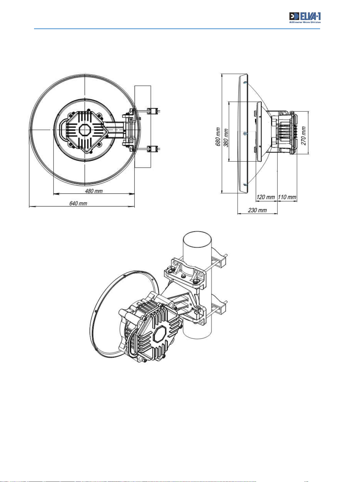
9.4 PPC-10G / PPC-10G-HP DRAWING
Page 42
PPC-10G Installation and User Manual
41
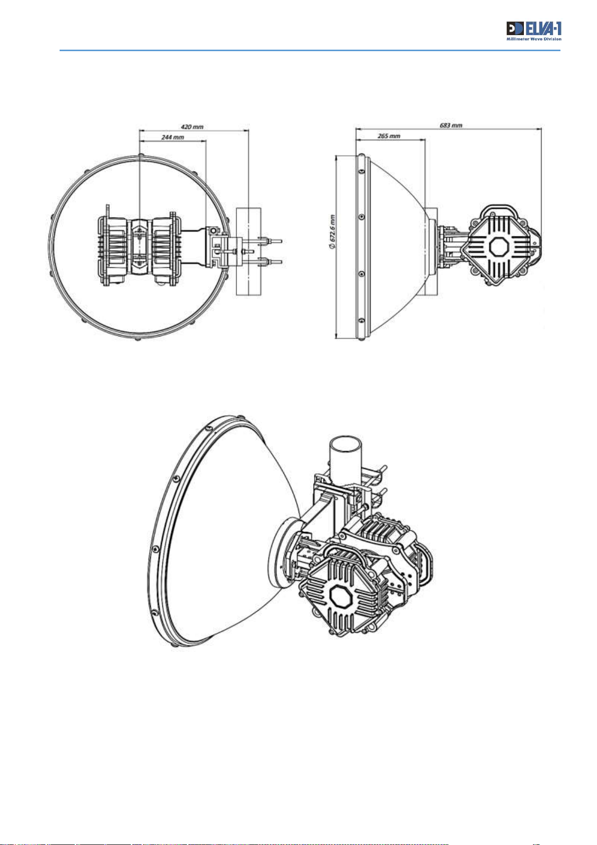
9.5 PPC-10G / 2+0 DRAWING
 Loading...