

Page 1
WS 2010
Radio Transmission
Weather Station
Operating Instructions
WEAT HERSTAT ION WS2000
TEMP. TEMP.
HUMIDITY
°F
%
N
NW NE
W
AM
S
Indoo r
Fast
mph
SESW
RAINF ALL
TOTAL
E
Prog.
Min / Max
Min / MaxCalibr.
1
WS 2010
°F
REL AT IVE AIR PRE SSURE
in
-16h -12h
-20h
-24h
Sensor
-8h -4h -1h
HUMIDITY
inHg
0h
TREND
Outdo orSensorResetWin d Rain Alar m
StoreSensorUnit
%
Page 2

2
Page 3

Contents
1. General Information and Function
2. Preparation for Operation
2.1. Inserting the magnets in the outdoor sensors
2.2. Preparing the base station
2.3. Description, assembly and starting up the measured value transmitter
2.3.1 Indoor radio sensor S 2010 ID
2.3.2 Wind radio sensor S 2010 W
2.3.3 Rainfall measuring system S 2010 R
2.3.4 Addressing the radio sensors S 2010 I, S 2010 IA, S 2010 A
2.3.5 Indoor radio sensor S 2010 I
2.3.6 Indoor/Outdoor temperature radio sensor S 2010 IA
2.3.7 Outdoor radio sensor S 2010 A
2.3.8 Notes on storing the solar cell power supplied outdoor sensors
3. Operation
3.1. Indoor values
3.2. Wind
3.3. Rainfall
3.4. Min./Max. function
3.5. Alarm function
3.6. Sensor selection
3.7. Outdoor display field
4. Program Mode
4.1. Setting the alarm min./max. values
4.2. Calibration
4.3 Changing units of measurement
4.4. Setting the clock
4.5. Changing the basic addresses of sensors with fixed assignments
5. Changing the Batteries
6. Faults
7. Technical Data
8. Range
9. Repeater for Increasing the Range
10. Glossary
11. Quick Reference
1st Edition, English, June 1999 Version 1.1, Order-No.
All rights reserved. This manual or parts of it may not be duplicated or copied or processed in any form
by electronic, mechanical or chemical means without the explicit written permission of the publisher.
It is possible that the contents of this manual contain technical printing faults and printed errors. The
specifications provided in this manual are regularly reviewed and errors corrected in the subsequent
editions. We are not liable for technical or printing faults nor their consequences. All trademarks and
industrial property rights are acknowledged.
Printed in Hong Kong
3
Page 4

1. General Information and Function
The Comfort Radio Weather Station WS 2010 represents a highly sophisticated,
easy to use, universal weather station which can record, evaluate and display data
from up to 9 external radio sensors for temperature and humidity, a radio sensor for
wind and another for rain.
The measuring options provided by the WS 2010 are listed below:
- Indoor temperature and humidity with air pressure and one of eight other temperatures with associated relative humidity.
- Up to 9 different, combined humidity/temperature measuring points, of which
two are displayed simultaneously in the display.
- Calculation and display of the windchill equivalent temperature.
- Air pressure, inHg or hPa.
- Air pressure tendency display (steady, rising, rising steeply, falling, falling steeply).
- Graphical display of the air pressure changes over the previous 24 hours.
- Symbolic display for weather forecast (sunny, clear, cloudy, rain).
- Wind speed, selectable in mph, knots, m/s, km/h or Beaufort scale.
- Wind direction in the form of a wind rose displaying wind direction fluctuation
(instead of wind speed, the wind direction can be displayed with 5% resolution)
- Integrated clock for accurate assignment of measured values.
- Storing of the minimum and maximum measured values for all sensors with associated time and date (the wind direction is also displayed with the wind speed).
- Compilation of the rainfall in ins. or mm (as total, over 24 hr. or over 1 hr.).
- Programmable alarm option for certain weather conditions, e.g. danger of frost,
storm, unfavorable air pressure and temperature tendencies when at sea, in the
mountains, or as an indicator for so called biological weather, for instance.
All the important weather information appear simultaneously in the display, so that
no operations on the unit are necessary to establish the weather.
Several basic units can be operated simultaneously enabling the data from sensors at various points to appear in the display at the same time
Please read this operating instruction manual thoroughly before using the
equipment for the first time in order to prevent functional faults and incorrect
operation.
Pay special attention to the assembly and calibration notes on the measuring
transmitters.
4
Page 5

The WS 2010 indoor/outdoor sensor system operates exclusively with radio data
transmission. This means that the measuring value transmitters can be placed up
to 100 m from the base station (depending on local conditions, refer to Section 8
‘Range’). Therefore, pay careful attention to the positioning and assembly instructions concerning these components to ensure the entire system works correctly.
Please note that in order to operate the weather station, at least one radio
sensor is required because the basic unit has no sensor of its own.
2. Preparation for Operation
The outdoor sensors for measuring the wind speed, rainfall and outdoor temperatures and relative humidity are equipped with a solar cell for power supply and
lithium battery for periods of darkness and bad weather.
To protect the valuable battery from total discharge during a longer period of storage
without the solar cell being exposed to light (e. g. in its packing), the power supply
for the initial operation is activated by a small magnet, inserted from the outside.
Therefore, the magnet belonging to the respective sensor should be inserted just
before the outdoor sensor is installed outside.
In order to ensure the unique assignment of sensor data, the basic unit should
only be put into operation after the sensors have all be running for ten minutes.
This is an important point because the sensors operate in a test sttarted mode for
up to ten minutes after the operating power is applied (inserting the magnets in the
outdoor sensors or inserting the batteries in the indoor sensors). During the test
phase, data is transferred in a 4-second cycle instead of a 3-minute cycle.
The outdoor temperature and relative humidity sensors must be addressed according to Section 2.3.4.
2.1. Inserting the magnets in the outdoor sensors
In the case of the outdoor radio sensor S 2010, the magnet to activate the system
is inserted in a opening designed for the purpose in the housing cover.
Activating the wind transmitter is also performed by inserting a small magnet in the
opening provided. The magnet holder is located above the retaining tube (opposite
the solar cell).
To insert the magnet in the rainfall measuring system S 2010 R, the upper section
of the casing must be separated from the lower section by pressing it and turning it
clockwise. The housing cover of the funnel integrated in the electronics casing is
equipped with a clip-in holder for the small, round magnet. After pressing the magnet into the holder, the rainfall measuring system starts to transmit.
5
Page 6
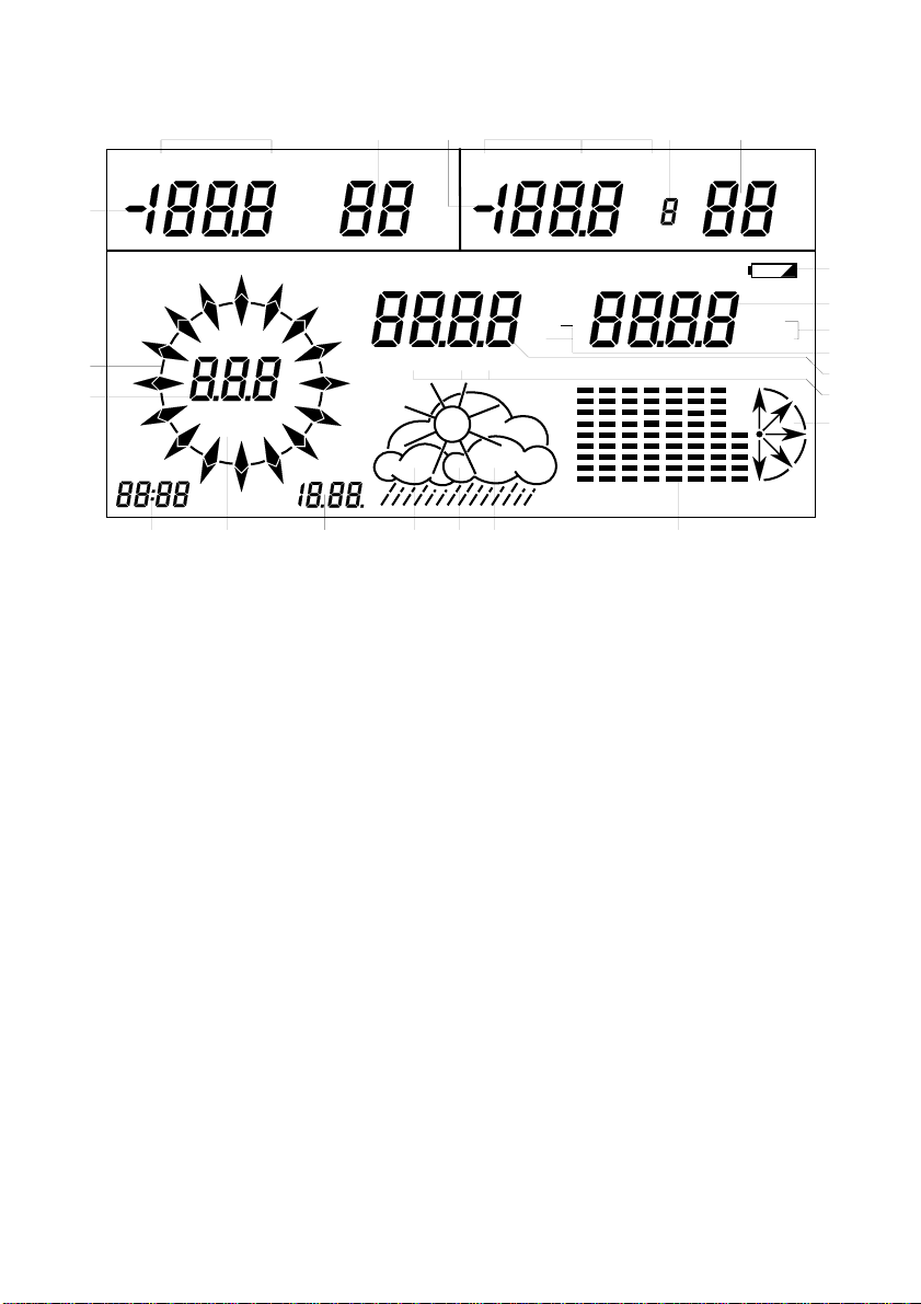
View of the display area
23
22
TEMP.
1
NW NE
W
AM
PM
19
2
DEWPOINT
N
PROGRAM MODE
Beaufort
m/s Knots
km/h
S
21
°F
°C
o
mph
SESW
20
3
HUMIDITY
TOTAL 24h 1h
E
MIN MAX
17
WIND CHILL TEMP.
%
RAINFAL L
18
16
5
647
DEWPOINT
HUMIDITY
°F
°C
Sensor
RELAT IVE AIR PRESS URE
mm hPa
in
CALIBRAT ION
≥
8
ALARM
+6
+4
+2
0
-2
-4
-6
≤
-8
-12h -8h
-16h
-20h-24h
-1h
-4h
15
in Hg
0h
%
8
9
10
11
12
13
14
TREND
1. Indoor or indoor/outdoor temperature sensor
2. Current indoor measurement: temperature or dew point
3. Indoor or indoor/outdoor humidity sensor
4. Temperature of selected outdoor temperature/humidity sensor
5. Current outdoor measurements: windchill or temperature or dew point
6. Display of selected outdoor sensor
7. Humidity value of selected outdoor sensor
8. Battery capacity indicator
9. Air pressure indicator
10. Air pressure unit: inHg or hPa
11. Rainfall quantity unit: ins. or mm
12. Rainfall quantity
13. Rainfall measuring period: total or past 24 hrs. or last hr.
14. Air pressure tendency
15. Air pressure history over past 24 hours
16. Weather forecast symbol
17. Symbol to call in minimum values
18. Symbol to call in maximum values
19. Time display
20. Date display
21. Wind speed unit: mph or knots or m/s or km/h or Beaufort
22. Wind speed or wind direction (in steps of 5°)
23. Wind rose, display in steps of 22.5° with fluctuation range of wind direction
changes
6
Page 7

2.2. Preparing the base station
Preparation of the base station simply comprises inserting four round cells (alkali)
in the two battery compartments on the rear side of the unit. Refer to Chapter 5
‘Changing the Batteries’ for instructions.
The base station should only be switched on after the connected sensors have
been in operation for at least ten minutes.
Then install the unit at the required site by means of the positioning clamp or hang
it up using the eyes integrated in the rear side of the housing.
After inserting the battery, there is a short initialization phase during which all the
segments of the display are indicated.
Following the segment test, the WS 2010 automatically switches to a so called test
mode during which all the received data appears in the display and is acknowledged by an acoustic signal. For more clarity, only the data received from the last
sensor is displayed and the previous data received is deleted. This makes it easy to
check that data is being received correctly from all the sensors.
In areas of unfavorable reception conditions, this test mode also simplifies determining the best location for equipment. The sensor in question can be switched to
test mode so that it transmits a telegram every 4 seconds.
To activate test mode, remove the batteries from the indoor sensors and the magnets from the outdoor sensors, wait for five minutes and insert them again.
The test mode running on the base station is automatically stopped after approx.
30 minutes and it switches to normal operation. Test mode can be stopped at any
time by pressing a button.
In order to assign the sensor data uniquely, the test mode on the base station
may only be stopped when all of the sensors are no longer in test mode.
When the test mode has been completed, i.e. when all the sensors have been
clearly assigned, set the time and date according to Section 4.4.
The time plays a central roll with regard to some of the unit’s display functions.
To simplify starting up, take the base station to within the vicinity of the sensors.
The correct transmission of data from the sensor can then be checked.
After the test phase, the data in the installed sensors is transmitted in a cycle of
about 3 minutes and appears in the fields in the display. Please refer to the data on
the adjacent page in respect of the position of the various data in the display.
2.3. Description, assembly and starting up the measured value transmitter
The sensors in the WS 2010 are divided into two groups. The basic requirement to
operate the weather station is the indoor radio sensor S 2010 ID (refer to Section
2.3.1 for more information). It transmits a fixed data telegram which permanently
displays the temperature and humidity in the field for indoor values at the top left of
the display. The sensor is immediately operational since an addressing is only necessary in a few exceptional cases.
Addressing is only necessary if two base stations with respective indoor sensor are
to be operated within the sensor range (up to 100 m). Base station 1 should display
the data from indoor sensor 1 and base station 2 the data from indoor sensor 2.
7
Page 8

The rainfall radio sensor S 2010 R and wind sensor S 2010 W have fixed addresses
and also belong to this group because the measured values have defined positions
in the display (refer to Page 6 ‘View of the display area’.
The second group of sensors are the S 2010 I, S 2010 IA and S 2010 A. These
sensors transmit data signals for the outdoor indicator area at the top right of the
display. A maximum of 8 sensors can be chosen via the sensor selector in the
display. Therefore, these sensors must be assigned an address in order to define
their position in the right-hand display area. Observe the notes on addressing with
respect to these sensor types.
2.3.1 Indoor radio sensor S 2010 ID
The indoor radio sensor S 2010 ID requires two round cell batteries to operate. It
contains a temperature, humidity and air pressure sensor. The data transmitted
always appears in the indoor display area at the top left of the display. The S 2010
ID measures the indoor temperature, humidity and air pressure and is the central
component for displaying air pressure, air pressure tendency, weather tendency
and air pressure history.
To insert the batteries, open the battery compartment on the rear side of the housing. Read the information on polarity in the battery compartment and insert the
batteries accordingly. Then close the compartment. The sensor can then be brought to its installation site. Note that this sensor is not designed for use outdoors or
in rooms with high humidity. The sensor is operational directly after inserting the
batteries.
2.3.2 Wind radio sensor S 2010 W
The wind radio sensor compiles both wind speed and direction at the installation
site. It is supplied with power from a solar cell with backup battery for periods of
darkness. It is assigned a fixed address which the user cannot manipulate.
It can be installed on a mast or at the top of a wall. The important factor for the
installation site is that the solar cell in the sensor housing faces south and is in an
exposed space, i.e. the wind must
be able to approach the sensor from all sides. Accurate alignment of the sensor,
pointing the solar cell due south, is an essential factor because it represents the
reference point for measuring the wind direction. It must be assembled absolutely
vertically in the retaining tube in order to receive accurate measurements.
Screw the retaining tube and sensor tight, ensuring a firm fit of all the components.
In its basic setting, the wind sensor is in an exact North - South direction (solar cell
facing south) to ensure an accurate north reference point for the evaluation electronics.
8
Page 9
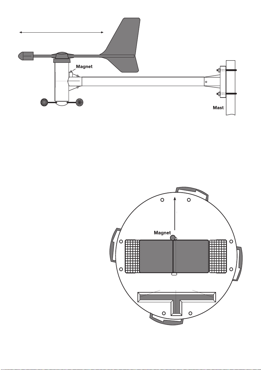
Example of
South North
the wind sensor
assembly on a mast
Solar cell
2.3.3 Rainfall measuring system S 2010 R
The rainfall measuring system is also solar powered and is provided with a fixed
address which cannot be manipulated by the user. The solar cell must be accurately aligned to face south.
The rainfall measuring system must be positioned on an absolutely horizontal surface and fixed by means of screws inserted in the holes in the base of the housing.
Remove the upper section beforehand by pressing it and
turning clockwise. There is a recess in the lower section which,
when filled with water, provides
a perfectly horizontal alignment
South
without any other resources required. Fill the recess with a little water and then align the lower
part of the housing according to
the spirit level principle. After
marking the installation position
exactly, drain off the water. Ensure the solar cell faces south.
The short side of the integrated
spirit level must point north (re-
Spirit level
Even water level at all three ends
fer to diagram).
To enable good transmission
(wide range), it is better not to set
the rainfall transmitter directly on
the ground. Installing it approx.
1 m above ground level produces the best results and protects
the system from dirt (especially
Aligning the S 2010 R. Using the spirit level
and position of the transmitting magnet
9
Page 10
the solar cells). After screwing the lower section to the base, replace the upper
section as follows:
In the middle of the counter rocker for rainfall on the lower section at the side is a
bar magnet which triggers the electronic counting pulses. The upper section of the
housing must be mounted so that the solar cell is also on the same side as magnet,
meaning that the electronics part is directly opposite and the three retaining latches fit exactly in the locks on the lower section. Then turn the upper section counterclockwise a little until it snaps into the locks in the lower section.
The rainfall sensor is then ready for operation. As a test, pour a little water in the
funnel very slowly. The amount is then displayed on the basic unit in inches or
millimeters.
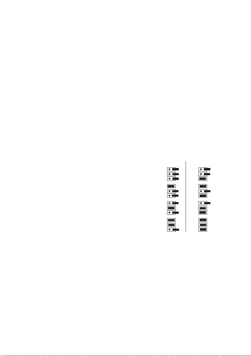
2.3.4 Addressing the radio sensors S 2010 I, S 2010 IA, S 2010A
The outdoor sensor concept enables the use of up to 8 sensors simultaneously
whose data appears at the top right of the display in the area for outdoor values.
Each sensor in the system must be assigned an address which enables the receiver to integrate the data within the complete system without any interference. At
the factory, each sensor of the type S 2010 A is defined as Sensor 1 and types S
2010 I and S 2010 IA as Sensor 2. The programmable assignment is illustrated in
the adjacent diagram. The addressing can be
performed by the user by setting the jumpers
on the component side of the sensor board.
First of all, unscrew the protective cover from
the S 2010 A and then open the housing sensor housing by removing the screws on the
rear side. The S 2010 I and IA only require the
rear panel of the housing to be removed.
Then set the jumpers labeled JP1, JP2 and
JP3 on the board according to the addressing table.
Sensor
8
7
6
5
Jumper
JP1
JP2
JP3
JP1
JP2
JP3
JP1
JP2
JP3
JP1
JP2
JP3
1 0
A0
A1
A2
A0
A1
A2
A0
A1
A2
A0
A1
A2
Jumper
1 0
JP1
JP2
JP3
JP1
JP2
JP3
JP1
JP2
JP3
JP1
JP2
JP3
Sensor
A0
4
A1
A2
A0
A1
A2
A0
A1
A2
A0
A1
A2
3
2
1
2.3.5 Indoor radio sensor S 2010 I
The indoor radio sensor S 2010 I corresponds to the indoor sensor S 2010 ID with
regard to operation and function. However, it only contains a temperature and humidity sensor, but no air pressure sensor. The sensor can be freely addressed for display within the outdoor display area at the top right of the display (refer to Page 6).
This address can be defined as required according to Section 2.3.4).
This sensor is well suited for use in indoor areas, such as a garage, cellar or even
attic, because it is battery operated and continues to function in the dark.
2.3.6 Indoor/Outdoor temperature radio sensor S 2010 IA
In order to operate, the S 2010 IA requires the insertion of 2 round cell batteries.
The electronically remote, encapsulated temperature sensor connected to a 5 m
long connection line enables it to measure the temperature in garden ponds or
ground areas, etc.
10
Page 11

This sensor can also be freely addressed for display within the outdoor display area
at the top right of the display (refer to Page 6).
This address can be defined as required according to Section 2.3.4).
The electronics housing can then be installed at the required location and the temperature sensor placed in or on the required object.
2.3.7 Outdoor radio sensor S 2010 A
The outdoor radio sensor S 2010 A enables the transmission of temperature and
humidity values related to the site of its installation.
This sensor can also be freely addressed for display within the outdoor display area
at the top right of the display (refer to Page 6).
This address can be defined as required according to Section 2.3.4).
The sensor should be installed in a shaded area because temperature information
in meteorological terms always relates to shaded areas. It can also be installed at
other sites, as required. It is only necessary to ensure that the solar cell which
provides the sensor with power is always exposed to light. The sensor should not
be located near obstacles, such as leaves, which cast shadows and interfere with
the power supply from the solar cell.
A good installation site, for example, is underneath a roof overhang.
The sensor is designed for installation on a mast or wall and should be mounted as
follows: Mount the sensor wall bracket either exactly vertical on a wall using four
screws or on a mast using the holding clamp.
Insert the sensor in the wall bracket and screw the parts together using the screws
supplied. The protective cover should be at the top and the solar cell exposed to
light.
During periods of darkness or bad weather with little or no sunlight, power is provided to the sensor by an internal, solar buffered, backup battery system.
2.3.8 Notes on storing the solar cell power supplied outdoor sensors
These sensors receive their operating power supply from a solar cell which buffers
an internal battery for periods of darkness. If such a sensor remains out of operation for a longer period and receives no light, there is no risk to the internal battery if
the magnets, inserted to activate the operating voltage, are removed. The sensor
can thus remain stored, e.g. in its packing, for several years.
3. Operation
Following installation of the sensors and subsequently putting the base station into
operation (only terminate test mode after the last sensor test has been completed)
the data received appears in the
corresponding areas of the display. If nothing appears, refer to Section 6 ‘Faults’
note on eliminating faults.
Please note only that data is displayed for which the corresponding sensor as
been installed. This means, for example, that no rainfall measurement can be
displayed if no rainfall sensor has been installed.
11
Page 12
Since all relevant data appears in the display at the same time, operation is
basically confined to selecting sensors or more detailed weather data by pressing the relevant button.
The Chapter ‘Operation’ is only concerned with normal operation; the button labels above the row of buttons apply.
Functions which need to be programmed are described in the Chapter ‘Program
Mode’, which involves the labels underneath the row of buttons.
3.1. Indoor values
In normal operation, the indoor value area of the display at the top left indicates the temperature and humidity at the installation site of the indoor sensor.
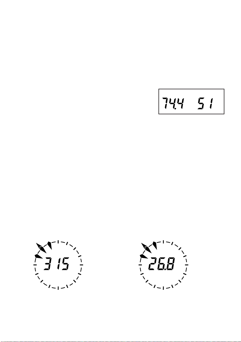
Press the ‘Indoor’ button once and the dew point
TEMP.
HUMIDITY
°F
%
appears (refer to ‘Glossary’).
Press ‘Indoor’ again to return to normal operation.
3.2. Wind
Pressing the ‘Wind’ button causes the unit of measurement for the wind speed
indicator to change or switches the wind speed indicator to a digital wind direc-
tion indicator, in steps of 5°, at the left-hand side of the display. The switching and
display sequence is as follows:
- wind speed in mph
- wind speed in knots
- wind speed in m/s
- wind speed in km/h
- wind speed in Beaufort scale
- wind direction in a 5° resolution instead of wind speed
N
NW NE
o
W
SESW
S
Digital display of the wind
direction
N
NW NE
E
W
mph
S
E
SESW
Digital display of the wind speed
in mph
12
Page 13
3.3. Rainfall
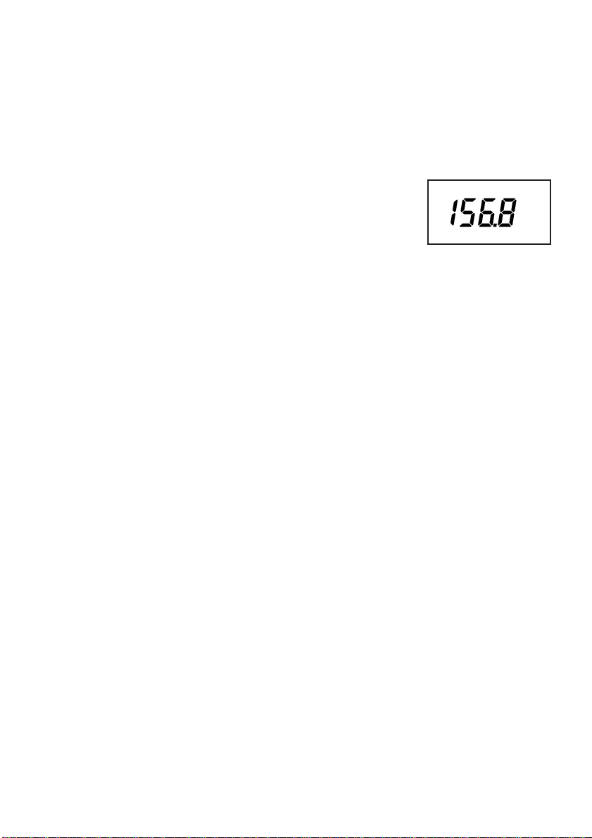
Pressing the ‘Rain’ button calls in the display of rainfall over the past hour (on
the half-hour of each hour), over the past 24 hours (compiled between 7:30 and
7:30 a.m.) and total rainfall (since beginning the measurement or last reset) in
sequence, positioned in the middle of the display.
The times and periods are based on internationally applied standards of meteorology.
Basic display: Total rainfall
Press x1: Last hour
Press x2: Last 24 hours
Press x3: Total rainfall (again)
RAINF ALL
in
TOTAL
(refer to diagram)
If the ‘Reset’ button is pressed for 2 sec. while the total rainfall is being displayed,
the accumulated value is deleted.
The time and date of deletion are stored by the weather station.
By pressing the Reset button briefly, the time and date of the last deletion are
displayed.
3.4. Min/Max function
The Min/Max function is used to call in the minimum and maximum values of all the
measured features since the last time the Min/Max memory was deleted. It is possible to select whether date or time of occurrence of the value should be displayed.
Min/Max value display
Press x1: Display all minimum values
Press x2: Display all maximum values
Press x3: Return to current display
If all the minimum or all maximum values are called in, there is no additional time
and date display. Neither are the weather symbol, air pressure or air pressure history displayed. Instead, the current selection appears, either MIN or MAX, at the
bottom of the display.
Delete all stored values
If the ‘Reset’ button is pressed for approx. 2 sec. during the Min. or Max. value
display, all the stored values are deleted.
Individual values with time and date
If the arrow button ‘ ->’ is pressed during the Min. or Max. value display, either
only the Min. or Max. value of the indoor temperature is displayed or, on pres-
sing the arrow button ‘<-’, the air pressure with relevant time and date.
------ All other display fields remain dark ----------------
13
Page 14
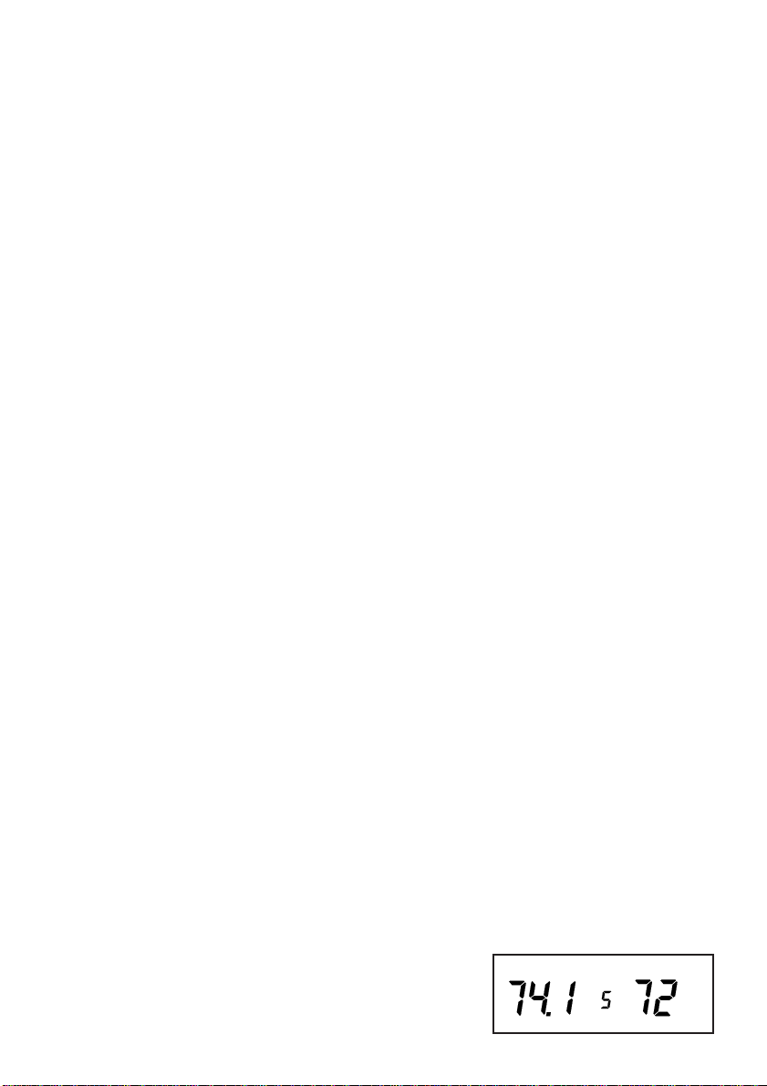
Using the arrow buttons and Min./Max. buttons, each individual minimum or
%
TEMP.
HUMIDITY
Sensor
°F
maximum value can be selected and appears in the display with the time and
date the corresponding value was stored.
------ All other display fields remain dark ----------------
In the case of the maximum wind speed, the system not only stores the time of
occurrence but also the wind direction at that moment.
Delete selected, stored value
If the ‘Reset’ button is pressed for approx. 2 sec. while the selected Min. or Max.
value is being displayed, the corresponding individual minimum or maximum
value is deleted.
3.5. Alarm function
As soon as one of the measured values received in the weather station rises above
or falls below an alarm value the tendency, air pressure history, weather symbols
and wind direction displays are all deactivated. Only those displays appear whose
values are outside the defined alarm limits. In addition, ‘ALARM’ appears.
If several display fields or measuring points are affected, their alarm displays also
appear.
By using the ‘Sensor’ button, the alarms from the outdoor sensors can be requested. The first alarm which arrives is displayed first with all the relevant sensor
information.
In the case of an alarm, the weather station remains in ‘Alarm’ status until the
‘Alarm’ button is pressed and the display of the current values reappears. The
system also issues an acoustic signal, consisting of five individual tones, in the
case of an alarm. The signal is issued every 30 minutes for a maximum of 7.5
hours. The alarm is deleted when the value at the measuring point concerned reverts to a value within the permissible range and pressing the ‘Alarm’ button. (The
current values return to the display.)
3.6. Sensor selection
The ‘Sensor’ button enables selection of the outdoor temperature/humidity
sensor regardless of the weather station operating mode. The sensor selected
appears in the ‘Sensor’ display field with its corresponding sensor number.
3.7. Outdoor display field
In normal operation, the outdoor display field at the top right indicates the temperature and humidity at the site of the sensor selected with the ‘Sensor’ button.
Press the ‘Outdoor’ button once and the Dewpoint
appears (refer to Glossary).
After pressing the ‘Outdoor’ button twice, the temperature display in this field changes to the Wind-
chill equivalent temperature. Obviously, the wind-
14
Page 15

chill display can only appear if the wind sensor S 2010 W is a component part of
the weather station.
After pressing the ‘Outdoor’ button again, the display returns to the normal temperature display.
4. Program Mode
Programming mode can be used to set the maximum and minimum values for the
alarm function.
Please note that the row of labels underneath the buttons applies and that if no
button on the unit is pressed within 60 seconds, it returns to normal operation
mode.
Activate Program Mode by pressing the ‘<-’ and ‘->’ buttons simultaneously.
PROGRAM MODE appears in the display together with the set minimum alarm
values. The weather symbols, air pressure tendency air pressure history and wind
rose are deactivated.
After pressing the Min/Max button, the maximum alarm values appear. If the Min/
Max button is pressed again, the minimum alarm values reappear. The alarm values, e.g. rising or falling below a certain ground temperature, exceeding a specific
wind strength etc., can now be adjusted in programming mode.
4.1. Setting the alarm min./max. values
Use the two arrow buttons ‘<-’ and ‘->’ buttons, and the ‘Sensor’ button, if necessary, to select the required measuring point or quantity.
Min/Max selection
The ‘Min/Max’ button is used in this mode to enter the minimum and maximum
values as required. The button function and function sequence corresponds to that
described in Section 3.4 ‘Min/Max Function’. Firstly, all the minimum then all the
maximum values can be entered or each measuring site can be assigned a minimum and maximum value directly.
Set values
Use the ‘+’ and ‘-’ buttons to set the required numeric value. Keep the button
pressed and the unit automatically increases or decreases the value correspondingly.
Increase counting speed
By pressing the ‘Fast’ ‘+’ or ‘-’ buttons simultaneously, the counting factor is
increased by 10.
4.2. Calibration mode
Calibration Mode enables settings to be defined which only needs to be carried out
once. It is used to calibrate the height compensation for baromeric air pressure,
balancing the rainfall transmitter and to set the required measuring units for air
15
Page 16

pressure and rainfall. An important function in Calibration Mode is setting the time
and date. This mode can also be used to adjust the address of the indoor sensor to
be received, the wind transmitter and rainfall transmitter when necessary.
Access Calibration Mode by simultaneously pressing the buttons ‘<-’ + ‘Calibr.’ +
‘->’ . Then use the arrow buttons ‘<-’ and ‘->’ to select the relevant display field.
Adjusting the height compensation for barometric air pressure
After selecting the air pressure display field, press the ‘+’ or ‘-’ buttons, together
with ‘Fast’ if necessary, to enter the height above sea level of the installation site in
meters (a value between 0 and 1999 is possible). Heights in feet must first be converted to meters using the factor 3.048. For example, if the air pressure sensor is at
a height of 1000 ft, the equation is 1000 : 3.048 = 328. Enter the value 328 as the
height compensation factor. The unit used in the display to indicate the pressure
has no effect on the height compensation of the barometric air pressure.
After pressing the ‘Store’ button, the values set are stored and the display returns
to normal operation.
Rainfall transmitter compensation
The rainfall measuring system leaves the factory in a very accurate state so
that readjustment should not normally be necessary.
A compensation is only necessary where an extremely high degree of accuracy is required.
Before beginning with the rainfall transmitter compensation, proceed according to
Section 3.3. ‘Rainfall’ with the display in normal operation to reset any accumulated rainfall quantity to zero.
Thenpour exactly 0.1 gallons of water, very slowly, into the funnel of the rainfall
transmitter.
Caution!
Pouring too quickly falsifies the measuring results. Pour the water so slowly
that no water remains in the funnel at any time.
The diameter of the funnel is 51.18 in., i.e. has a surface area of 0.206 sq. in., the
setpoint value of 0.1 gallons poured in must produce a rainfall total of 11.24 ins.
When the water has completely run through the funnel, the actual value in the
display should ideally read 11.24 in.
The ratio of setpoint value to actual value defines the calibration factor. However,
since a calibration factor has already been entered earlier, this must be taken into
account in the calculation.
New calibration factor:
Setpoint value (e.g. 11.24) x old calibration factor
Actual value (display value after filling the water
16
Page 17
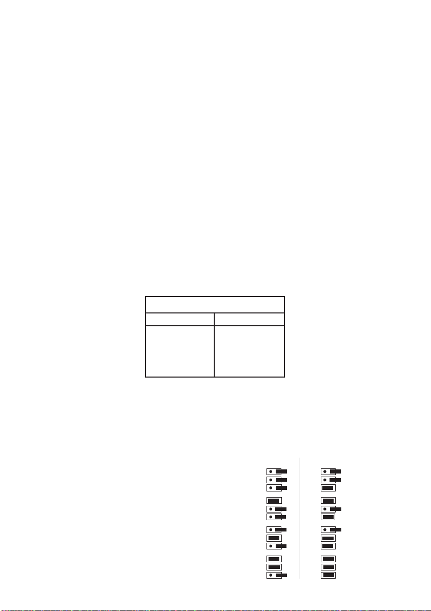
To obtain the old calibration factor, press the buttons ‘<-’ + ‘Calibr.’ + ‘->’ simulta-
neously tom access Calibration Mode. Press the ‘<-’ button to select the Rainfall
the display field.
After the first transmission from the rainfall transmitter, the old calibration factor
appears in the display. Press the ‘+’ or ‘-’ buttons, together with ‘Fast’ if necessary, to set the new value.
After pressing the ‘Store’ button, the value set is stored and the display returns to
normal operation.
4.3. Changing units of measurement
If the ‘Unit’ button is pressed when the system is in Calibration Mode, the following units can be selected in the corresponding display fields; in or mm in ‘RAIN-
FALL’, inHg or hPa in ‘RELATIVE AIR PRESSURE’ and, when the set sensor
address is being displayed, °F or °C for the various TEMP. displays.
4.4. Setting the clock
The weather station WS 2010 is equipped with an integrated clock which can also
be set in Calibration Mode.
When in Calibration Mode, (Section 4.2) press the arrow button ‘<-’ twice. Only the
time and date appear in the display. The setting can then be made according to
Table 1.
Table 1: Set Time and Date
Function Button
Hour Minute +
Month Unit
Day Sensor
4.5. Changing the basic addresses of sensors with fixed assignments
Adjusting the addresses of the indoor sensor S 2010 ID, rainfall sensor and wind
sensor is not necessary under normal circumstances.
The multifunctional operation represents a special feature, which enables any number
of basic units to be operated within the
respective radio sensor ranges. This
means that one base station can be
operated in the living room, another in
the office, etc. all displaying the same
data.
If a basic unit (display unit) is installed
in each room in which the indoor temperature is to be displayed in the first
display field (top left of the display), the
indoor sensors for temperature/humidity with air pressure must be assigned
Adresse
Address
7
6
17
A0
A1
A2
A0
A1
A2
A0
A1
A2
A0
A1
A2
Jumper
JP1
JP2
JP3
JP1
JP2
JP3
JP1
JP2
JP3
JP1
JP2
JP3
1 0
Address
A0
A1
A2
A0
A1
A2
A0
A1
A2
A0
A1
A2
Adresse
3
2
1
0
Jumper
1 0
JP1
JP2
JP3
JP1
JP2
JP3
JP1
5
JP2
JP3
4
JP1
JP2
JP3
Page 18

different addresses, according to the diagram below. The relevant jumpers are identified on the board with JP1, JP2 and JP3.
In order that the base station only receives data from the sensor assigned to it, the
corresponding address must also be set. To modify the basic address, activate
Calibration Mode and press the arrow button ‘<-’ three times and then select the
required address using the ‘Indoor’ button.
The basic address of the wind and rainfall transmitters can also be modified in this
operating mode, processes which are seldom necessary. Modifying the addresses
of the wind or rainfall transmitters is only necessary when two neighboring wind or
rainfall sensors are installed within the range of one base station. The basic addresses
of the wind and rainfall transmitters must be changed by the manufacturer, so that
it may be necessary to return the sensor concerned.
5. Changing the Batteries
Radio sensors S 2010 ID, S 2010 I and S 2010 IA
All the batteries in these sensors have a working life of up to 3 years (alkali batteries). They must be replaced when the display of the corresponding sensor does
not appear for over 24 hours and no other general, longer term interference in the
transmission path needs to be taken into account. This can generally be determined if data transmission from other sensors located nearby is not displayed either
(refer to Chapter 6 ‘Faults’).
The batteries are changed by opening the battery compartment on the rear of the
sensor housing, removing the used batteries and inserting two new round cell batteries of the type AA Alkaline, ensuring correct polarity according to the markings
on the compartment cover. The sensor is operational again after replacing the cover. The data from the sensor should reappear in the display after the base station
has completed its sensor polling cycle (refer to Chapter 6 ‘Faults’).
Base station WS 2010 B
The base station indicates that the battery is becoming weaker by means of the
battery symbol at the right of the display.
Since stored data is lost following a change of battery, call it into the display and
note down the values required.
Open both battery compartment covers on the rear side of the unit, remove the
four used, round cell batteries and inserting four new ones of the type AA Alkaline,
ensuring correct polarity corresponding to the markings in the compartments.
Other component parts of the system do not require changing the batteries
because they are driven via solar cells. Integrated backup batteries overcome
periods of darkness and bad weather.
18
Page 19

6. Faults
If transmission is not received from a sensor for 12 hours, its value disappears from
the display. At 8:00 a.m. and 6:00 p.m. the base station polls all sensor transmitters
for 6 minutes, in case intermittent radio interference on the path has affected the
synchronization between sensor and base station. Transmission occurs in a very
short period of time. After this period of 6 minutes, a faulty reception should have
been cleared.
Possible faults which prevent correct display of transmitted data are:
Undefined values after starting up
Note that the base station test mode may only be terminated when none of the
sensors is still test mode so that defined data can be received immediately and to
ensure the correct assignment of data telegram to display position
No reception - distance between transmitter and receiver is too great
Reduce the distance between transmitter and receiver.
No reception - interfering material between transmitter and receiver (thick walls,
concrete,...)
Find a new location for the transmitter or receiver. Also refer to Chapter 8.
Batteries of transmitter or receiver empty
Change batteries. Check base station battery indicator.
Transmitter superimposed by source of interference
(radio, headphones, loudspeakers)
Eliminate the source of the interference or find a new location for the transmitter. If
no data is received for 12 hours, the associated measuring point is deactivated so
that no more measured data is displayed because the system assumes that the
sensor no longer exists. No more attempts are made to receive data in order to
save battery power. At 8:00 a.m. and 6:00 p.m., the receiver automatically starts
new synchronization, whereby sensors which have not been received for over 12
hours are deactivated.
A newly added radio sensor (e.g. following a change of batteries) is automatically accepted by the system and the related data is displayed.
Faults are often restricted to limited periods (radio communication) or can be easily
eliminated. If a unit, e.g. radio headphones, babysitter, etc is operated your house
or a neighbor’s at 433 MHz, the period of activity is normally limited. Most of these
units can be changed to an interference-free frequency. Such measures can normally eliminate faults effectively.
Radio sensor interferes with other units
The transmissions from radio sensors can cause short-term interference on units
19
Page 20

operating on the same channel (every 3 minutes for approx. 200 ms).This interference is negligable. If possible, change the channel on the unit experiencing interference.
20
Page 21

7. Technical Data
Measuring interval, outdoor sensor: .............................................................. 3 min
Measuring interval, indoor sensor:................................................................. 3 min
Transmission frequency: ..................................................................... 433.92 MHz
Range in open space: ...........................................................................Max. 330 ft
Temperature range, indoors: .......................................................... 32 °F to 176 °F
Temperature range, outdoors: ...................................................... -22 °F to 176 °F
Resolution: .................................................................................................... 0.1 °F
Accuracy: .................................................................................................... +/- 1°F
Measuring range, rel. humidity:............................................................ 5% to 95%
Resolution: ........................................................................................................ 1%
Accuracy: .......................................................................................................... 8%
Measuring range, air pressure: .................................................... 800 to 1100 hPa
Resolution: .................................................................................................... 1 hPa
Accuracy: .................................................................................................+/- 1 hPa
Air pressure change: ..................................... Line diagram, scaled 2 hPa/part line
Rainfall quantity: .................................................................................. 0 to 1574 in
Resolution: ..................................................................................................< 0.2 in
Accuracy: .............................................................................................2% +/- .4 in
Wind speed: ...................................................................................... 0 to 124 mph
Resolution: .............................................................................................0.062 mph
Accuracy: ............................................................................................ 3% 0.7 mph
Wind direction: ............................. Graphic resolution 22.5°, numeric resolution 5°
Power supply: ................................................................................. 4 x round cells
Dimensions (W x H x D): ........................................................... 85,4 x 63 x 11.8 in
8. Ranges
Under optimum conditions, the open field range is 330 ft, i.e. when there is ‘visual’
contact between the transmitter and receiver. Walls and reinforced concrete constructions can be passed through, but they do affect the range correspondingly. A
reduced range may be due to the following reasons:
• High frequency interference of all types
• Buildings of all types and vegetation
• Especially in the case of the wind sensor, metal roofs or roof insulation with foil
sealed glass wool can reduce the range
• Transmitter and receiver clearance from conductive surfaces or objects which
affect radiation characteristic and thus the range (including human bodies and
the ground)
• Broadband interference in built-up areas may reach levels which lessen the entire signal-to-noise ratio, thus reducing the range
21
Page 22

• Units with neighboring operating frequencies may affect the receiver
• Poorly screened PCs may affect the receiver and reduce the frequency
9. Repeater for Increasing the Range
Buildings which reduce ranges can be compensated for by means of a special
repeater designed for the weather station. The battery powered repeater, equipped
with transmitter and receiver receives the data from the required sensors and transfers them on with only a minimum delay. The repeater is housed in a waterproof
casing and is suitable for installation both indoors and out. Several repeaters can
be cascaded to overcome greater distances.
10. Glossary
Air pressure history - storing and graphically representing the air pressure situati-
on over the past 24 hours. Used to draw conclusions concerning general weather
developments. Graphical display indicates changes of 2 hPa per part line.
Air pressure tendency - Calculated from the developments over the past hours
Dew point - A temperature point which is dependent on the combination of a
certain air pressure, temperature and humidity. At this point, the humidity starts to
condense, forming dew i.e. the humidity in the air becomes liquid. If the dew point
for the humidity in the air is below freezing point, condensation may lead to the
formation of frost.
Weather tendency - Weather forecast display by means of weather symbols, calculated from the speed with which the air pressure rises or falls.
Windchill equivalent temperature - A fictive temperature felt by people rather
than the real temperature measured, often used when temperature get low. It is
defined from how wind speeds feel at certain temperatures. The conditions relate
to temperatures under 91.4 °F and wind speed in excess of 2.6 m/s which have a
determined as a cooling effect on the naked skin at a constant skin surface temperature of 91.4 °F.
22
Page 23
Quick Reference
The button functions appear as consecutive steps on pressing the corresponding button repetitively. The first item indicates the display in its initial state The numbers in brackets indicate the
relevant section in the operating instructions. Calibration is described in Section 4.2
Normal operation (3) Buttons:
Indoor Wind Rain Alarm Sensor Outdoor
TemperatureSpeed mph Total Active Select Temperature
Humidity Speed, knots Last hour Alarm value Outdoor sensor Humidity
Dewpoint Speed m/s Last 24 hours Display Dewpoint
Humidity Speed km/s Alarm Humidity
Button
Min/Max (3.4) Arrow buttons (3.4) Reset
Wind direction Windchill
Humidity
Display all minimum values
Display all maximum values
Program Mode (4)
Activate Program Mode by pressing the two arrow keys simultaneously
Display: PROGRAM MODE
Setting alarm min/max values (4.1)
Use the arrow buttons ‘<-’ or ‘->’, and the ‘Sensor’ button if necessary, to select the required
measuring point or measuring quantity.
Min/Max selection: Use the Min/Max buttons to enter any minimum or maximum values required.
The button functions and function sequence corresponds to the Min/Max function described above. In this way, all the minimum values can be set at first then the maximum values, or the respective min. and max. values can be set on the individual sensor.
Set value: Use the ‘+’ and ‘-’ buttons to set the required values. Hold the button pressed in and the
unit automatically counts up or down, respectively.
Increase counter speed: The counting speed factor can be increased by 10 by pressing ‘+’ ‘-’
and ‘Sensor’ buttons simultaneously.
Calibration (4.2)
Calibration Mode, display: CALIBRATION (press the buttons ‘<-’ ‘Calibr’ and ‘->’ simultaneously). The display fields for air pressure sensor, rainfall transmitter and clock can be selected using
the ‘<-’ and ‘->’ buttons. The basic addresses of sensor assignments (4.5) can be changed and
display of temperature in °F or °C selected. The settings for height compensation regarding barometric air pressure and correction of the calibration factor for the rainfall transmitter can be modified using the ‘+’ and ‘-’ buttons. The time and date are set according to Table 1.
Changing unit of measurement (4.3)
After pressing the ‘Unit’ button, the RAINFALL display can be set to in or mm, RELATIVE AIR
PRESSURE to inHg or hPa and temperature displays to °F or °C.
Pressed when min. or
max. values are displayed: individual display of
the stored values of the
individual measuring
points with date and time
of occurrence of the min.
and max. value
23
Press 2 s during normal operation
Delete accumulated rainfall total
Press 2 s when min. or max. values
are displayed: delete all stored values
(min. or max.)
Press 2 s during selective display via
the arrow buttons: Only delete min.
or max. value of the selected measuring point.
 Loading...