

Page 1

1
ELV Elektronik AG • Postfach 1000 • D-26787 Leer • Telefon 0491/600-888 • Telefax 0491/6008-244
Programmable
Soldering Station
LS 50
User Manual
Page 2

32
List of contents
Page
Introduction ...................................................................................... 2
Proper Use ....................................................................................... 2
List of Contents ................................................................................ 3
Safety Instructions............................................................................ 4
Description of Functions................................................................... 5
Brief Summary of Instructions for Use ............................................. 6
Instructions for Use .......................................................................... 6
1. Setting up ................................................................................... 6
2. Switching on ............................................................................... 7
3. Adjusting the set point temperature with the ,,+”/ ,,-” keys ......... 7
4. Selecting one of the programmed set point temperatures ......... 7
5. Modifying the programmed set point temperatures .................... 8
6. Manual standby function ............................................................ 8
7. Timer-controlled standby function ............................................ 10
8. Automatic power-off function .................................................... 11
9. Disabling the power bar-chart .................................................. 11
10. Switching over between °C and °F ......................................... 12
11. Calibrating the temperature reading by software.................... 12
12. Potential equalization ............................................................. 13
13. Attaching a new soldering tip.................................................. 13
Handling ......................................................................................... 14
Maintenance................................................................................... 14
Disposal ......................................................................................... 16
Troubleshooting.............................................................................. 16
Technical Data................................................................................ 16
Introduction
Dear customer, First of all we should like to thank you for purchasing
this product.
You have, with this soldering station, acquired a product whose design
and construction are completely state-of-the-art. To ensure safe
operation, you as the user must always observe these Operating
Instructions
Proper Use
●
This soldering station is intended exclusively for the purposes of
soldering and unsoldering electrical and electronic components
on printed circuit boards and modules, for solder-coating conductive
patterns and cable ends, and for manufacturing cable connectors.
●
It is not allowed to use the soldering station to heat liquids or plastics.
●
The soldering station may only be used indoors, i.e. not in the
open air. Contact with dampness or humidity, e.g. in a bathroom
etc., must be avoided under all circumstances.
●
Use other than that described above will result in damage to this
product and involves the risk of hazards such as short-circuit, fire,
electric shock, etc. The case must not be opened and no part of
the product may be modified or converted.
●
The Safety Instructions must be observed under all circumstances.
Page 3

54
●
The appliance is not intended for use by young children or infirm
persons without supervision.
●
Do not leave the packaging material Iying around. In the hands of
children, plastic film / bags, polystyrene foam, etc. may become a
dangerous toy.
●
In commercial premises, the accident prevention regulations of the
Association of Industrial Professional Associations with respect to
electrical systems and operating equipment must be observed.
●
In schools, training institutions, and hobby and self-help workshops,
use of any device operated via mains power must always be
supervised by responsible and properly trained personnel.
●
Warning- The soldering iron must be placed on its stand when not
in use.
Description of Functions
The LS 50 soldering station is made for excellent soldering
convenience. Thanks to its processor control it has been possible to
implement a wide variety of useful features, e.g. the direct selection of
up to three programmable set point temperatures, the standby and
automatic power-off functions, plus a liquid-crystal display (LCD).
Particularly in day-to-day operation, the user quickly learns to
appreciate the advantages of a soldering station with special
convenience features of this nature.
With the LS 50 it is possible not only to adjust the set point temperature
by means of the „+” / „-” keys but also to program up to three
temperatures (or, alternatively, two temperatures plus a standby
temperature) which can be quickly selected at the touch of a button.
The soldering station can thus be prepared on an individual, taskoriented basis for the most varied soldering jobs, e.g. PCB work, wiring,
or soldering an insulating case.
The multi-function LCD provides clear, at-a-glance indication of all the
important parameters. It displays the current actual temperature in
extra large digits. At the same time it also displays the three
programmed set point temperatures. It can also display a bar-chart
providing a clear overview of the heat currently being supplied to the
soldering iron.
Further features, particularly useful in day-to-day use, are the integrated
Safety Instructions
●
The warranty will become void in the event of any damage caused
by failure to observe these Operating Instructions. We cannot
accept any liability for consequential damage.
●
We cannot accept any liability for damage to property or physical
injury caused by improper use or failure to observe the Safety
Instructions. The warranty will become void in such cases.
●
For reasons of safety and of certification no conversion or
modification of the soldering station is permitted.
●
The only power source permitted is an approved mains socket
(230-240 volts / 50 Hz) properly installed and connected to the
public power supply grid.
●
Please ensure that the soldering station is set up, switched on,
and operated in a proper, workmanlike and technically correct way,
always carefully observing these Operating Instructions.
●
If you have any doubt regarding the connection, safety measures
or operation of this device, please contact a specialist.
●
Having switched the soldering station on, never leave it unattended
in this condition.
●
Never use the soldering station in the proximity of any easily
inflammable, ignitable or combustible substances or gases.
●
Soldering releases vapours that represent a health hazard.
●
Always ensure that the workplace is well ventilated or use a suitable
extractor system.
●
Always be sure to protect your eyes and body from solder splashes
by wearing suitable goggles and clothes.
●
Always ensure when setting up the soldering station that the mains
cable cannot be squashed or damaged by any sharp edges.
●
Never place the soldering station in the proximity of any easily
inflammable or combustible materials, e.g. curtains.
●
Never expose the soldering station to any high temperatures, strong
vibrations, or humidity.
●
No device operated via mains power should be treated as a children
toy.
●
Young children should be supervised to ensure that they do not
play with the appliance.
Page 4
76
2. Switching on
The soldering station can be switched on by means of the „Power”
switch. The processor then performs a segment test, i.e. all 108
segments are activated for approximately two seconds.
This is followed by the heat-up phase. The soldering iron heats up
until it reaches the set point temperature in effect just before the device
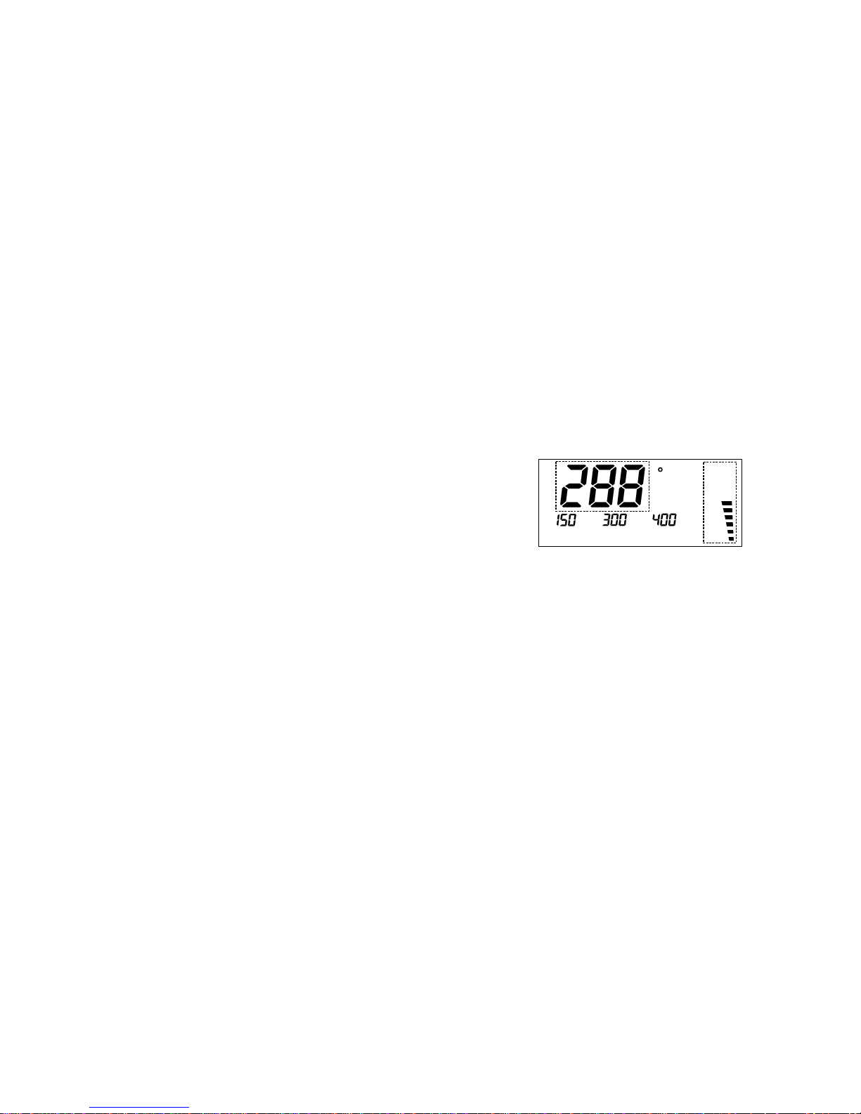
was switched off the last time. The LCD shows the current actual
temperature in the main display section and the „Power” bar-chart
(which can be disabled) indicates the heat being supplied to the
soldering iron; (see Figure 1). As soon as the set point temperature is
reached, the soldering iron is maintained constant at this temperature.
Figure 1
C
Power
3. Adjusting the set point temperature with the „+” / „-” keys
The set point temperature can be adjusted inter alia by means of the
„+” and „-” keys.
As soon as one of these keys is pressed, the main display section
(see Figure 1) changes to show the set point temperature. This set
point temperature can then be jogged up or down in steps of 1° each
time the key in question is pressed. If the key is pressed and held
down, the set point temperature is incremented / decremented initially
in 1° steps for the first 10 digits and then subsequently in 10° steps. As
soon as the desired value is reached, the key must be released.
The main display section, after approximately three seconds, switches
back to showing the current actual temperature.
4. Selecting one of the programmed set point temperatures
The feature with the programmed set point temperatures provides real
soldering convenience. For different soldering jobs the most suitable
temperatures can be selected quickly and conveniently at the push of
standby and automatic power-off functions. The standby / automatic
power-off timer can be adjusted in 5-minute steps up to a maximum of
9 hours and 55 minutes. On expiry of this programmed timeout the
LS 50 automatically sets the preprogrammed standby temperature or
switches off completely. The standby mode can of course be activated
and deactivated at any time at the push of a button.
The soldering iron on the LS 50 operates with 48 W. It can thus heat
up to the desired working temperature very quickly and with plenty of
power in reserve. The processor determines the current actual
temperature via the integrated temperature sensor and regulates the
power of the soldering iron accordingly. As and when necessary a
new soldering tip can be attached very easily and quickly by simply
undoing the screw connector.
Brief Summary of Instructions for Use
1. Set up the device and insert the soldering iron plug in the DIN socket
on the station.
2. Switch on by means of the ,,Power” switch.
3. Adjust the set point temperature as desired by pressing the „+”/„-”
keys.
4. You can select one of the programmed set point temperatures by
pressing the appropriate „T1” /„T2”/„T3”key.
5. You can modify a programmed set point temperature by pressing
and holding down the appropriate „T1” / „T2”/ „T3” key and, while
doing so, adjusting by means of „+” or „-”.
Instructions for Use
In order to ensure that the device is used properly and as intended,
please be sure, before using the device, to read through these
Operating Instructions and Safety Instructions carefully and completely.
1. Setting up
First the device must be set up at your workplace and connected to a
mains socket. The plug from the soldering iron must then be inserted
in the DIN socket located on the front of the station. The solder sponge
must be laid in the stand and moistened.
Page 5
98
C
Power
Standby
Standby
C
Power
Standby
Prog
C/FPower
C
Power
Standby
Prog
C/FPower
Figure 3
The device is shipped with the manual standby function disabled. If
you prefer to have this function enabled, the LS 50 must first be
switched to programming mode. To do so, press keys „T1”, „T2” and
„T3” together at the same time. When the LS 50 is in programming
mode, this is indicated by the ,,Prog” segment; (see Figure 4).
Figure 4
Now in programming mode the manual standby function can be
enabled by pressing key „T1". The arrow segment appears above this
key; (see Figure 5). Pressing „T1” again disables the function again
and the arrow segment disappears. After a period of three seconds
after the last time a key was pressed the LS 50 quits programming
mode automatically and returns to normal display.
Figure 5
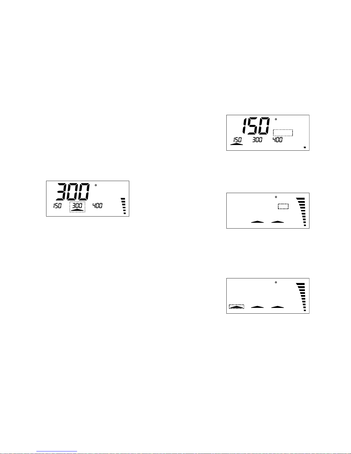
a button. The device is shipped with the following set point temperatures
already programmed: 150 °C, 300 °C, and 400 °C.
These programmed set point temperatures are indicated above the
keys „T1”, „T2” and „T3” in the display. When one of these keys is
pressed, the assigned temperature is used as the set point. After one
of these keys has been pressed, the main display section shows the
assigned temperature for approximately three seconds and then
switches back to showing the current actual temperature.
An arrow above one of these keys signals that the assigned programmed
temperature has been activated as set point; (see Figure 2).
Figure 2
C
Power
5. Modifying the programmed set point temperatures
If you prefer to have different set point temperatures programmed,
these can easily be modified. To do so, the key below the temperature
you wish to change (T1, T2, T3) must be pressed and held down.
While this key is held down, the assigned temperature can be adjusted
up or down by pressing the „+” / „-” key. As soon as you release the
keys, the new temperature value is saved.
6. Manual standby function
In jobs involving long pauses between soldering actions it makes good
sense to lower the temperature of the soldering iron. This reduces
energy consumption and saves wear on the soldering tip. To do so,
key „T1” can be reprogrammed as stand by key. Subsequently, when
this key is pressed, the soldering iron starts cooling down to the
programmed set point temperature „T1”. This is indicated in the display
by the ,,Standby” segment; (see Figure 3). And as soon as the key is
pressed again the previous set point temperature is re-activated.
Page 6
1110
8. Automatic power-off function
It is also possible to program the LS 50 so that the soldering iron, after
a programmable timeout, automatically switches off. The LS 50
indicates this by displaying „OFF” in the main display section. As soon
as any key is pressed, the device quits the power-off mode.
The device is shipped with the power-off function disabled. If you prefer
to have this function enabled, the LS 50 must first be switched to
programming mode. To do so, press keys „T1”, „T2” and „T3” together
at the same time. When the LS 50 is in programming mode, this is
indicated by the „Prog” segment; (see Figure 4). Now in programming
mode the power-off function can be enabled by pressing and holding
down key „T2”. The power-off timeout can now be adjusted in 5-minute
steps up to a maximum of 9 hours and 55 minutes by means of the
„+”/„-” keys; (see Figure 7).
Figure 7
If the power-off timeout is set to „0”, the power-off function is disabled
again and the timeout display disappears. After a period of three
seconds after the last time a key was pressed the LS 50 quits
programming mode automatically.
Notice: After programming the Automatic Power-Off time the
programmed data only becomes valid after switching the solder station
off and then back on.
9. Disabling the „power” bar-chart
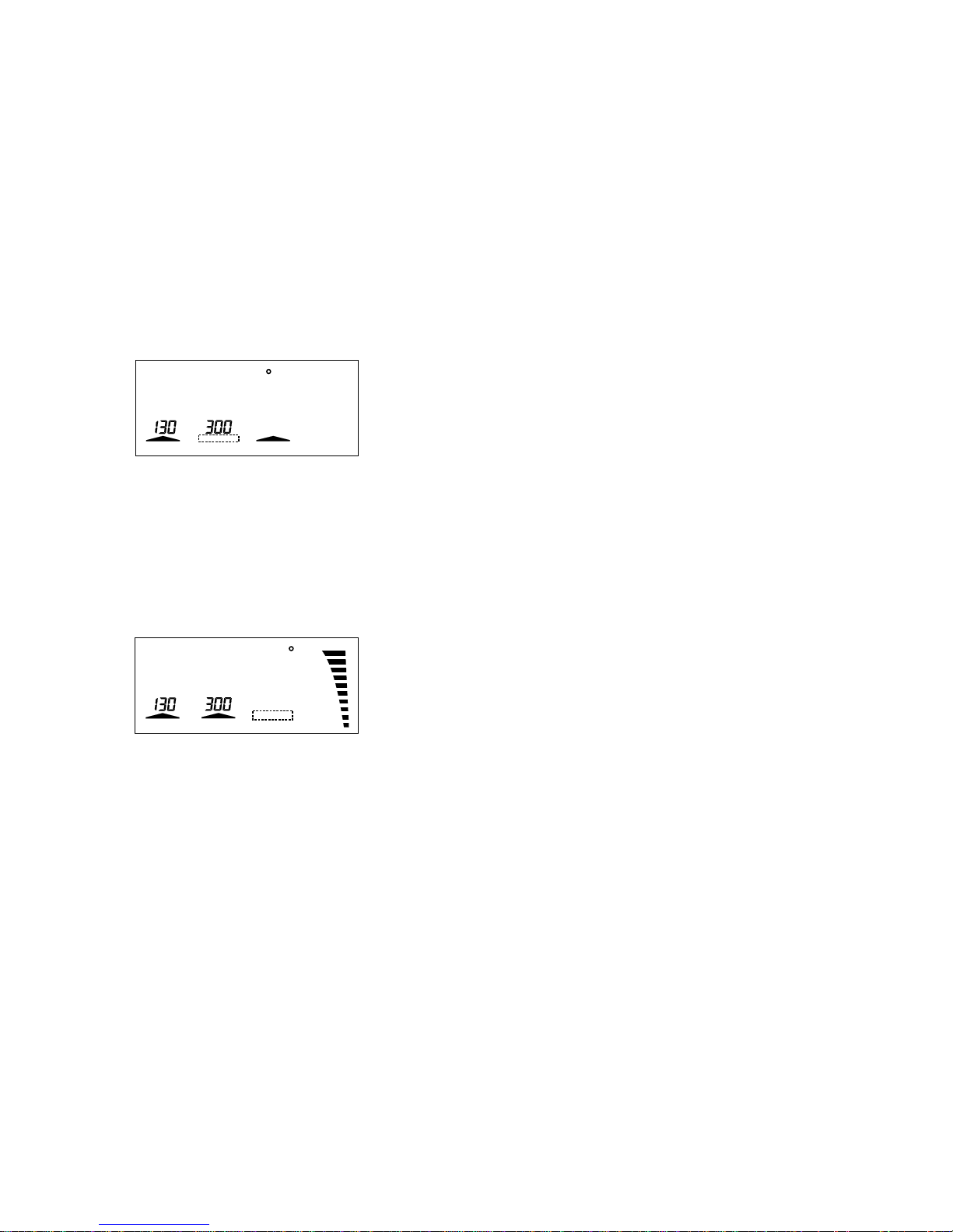
The „power” bar-chart display can be disabled. To do so, the LS 50
must first be switched to programming mode by pressing keys „T1”,
„T2” and „T3” together at the same time; (see Figure 4). Now in
programming mode the „power” bar-chart can be disabled by pressing
key „T2”. The arrow segment above this key disappears; (see Figure 8).
Pressing „T2” again re-enables the bar-chart display. After a period of
C
Power
Standby
Prog
C/FPower
7. Timer-controlled standby function
The timer-controlled standby function has the effect of lowering the
working temperature automatically after expiry of a programmable
timeout. This timeout is calculated from the last time a key was pressed.
If the standby period has been programmed e.g. as one hour, the
soldering station switches to standby mode exactly one hour after the
last time a key was pressed. In this condition, as soon as any key is
pressed, the soldering station quits standby mode again.
The device is shipped with the timer-controlled standby function disabled.
If you prefer to have this function enabled, the LS 50 must first be
switched to programming mode. To do so, press keys „T1”, „T2” and
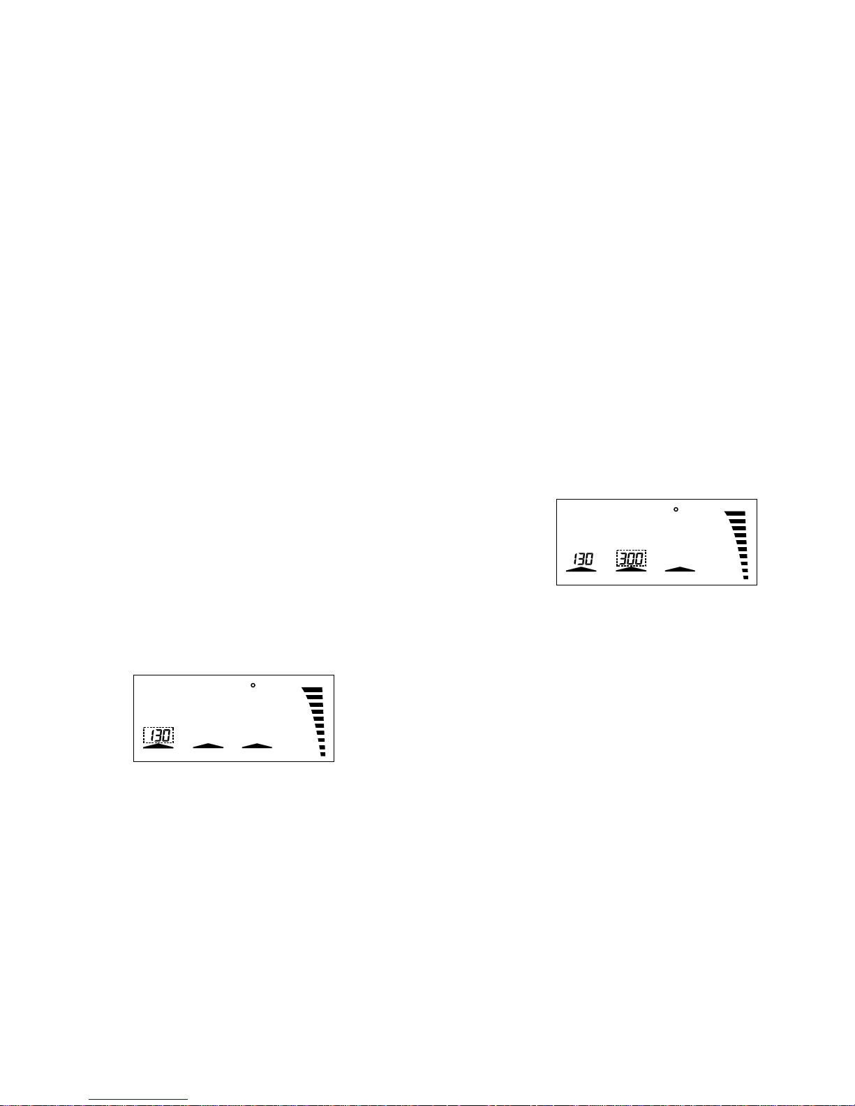
„T3” together at the same time. When the LS 50 is in the programming
mode, this is indicated by the „Prog” segment; (see Figure 4).
Now in programming mode the timer-controlled standby function can
be enabled by pressing and holding down key „T1”. The standby
timeout can now be adjusted in 5-minute steps up to a maximum of 9
hours and 55 minutes by means of the „+”/ „-” keys; (see Figure 6).
If the standby timeout is set to „0”, the timer-controlled standby function
is disabled again and the timeout display disappears.
After a period of three seconds after the last time a key was pressed
the LS 50 quits programming mode automatically.
Notice: After programming the standby time the programmed data only
becomes valid after switching the solder station off and then back on.
Figure 6
C
Power
Standby
Prog
C/FPower
Page 7
1312
For this purpose you should use a measuring unit with stable operation
up to a temperature of at least 350 °C.
In order to activate calibration mode, you must, during the switchingon process, press key „T1”. „CAL 20” appears in the display together
with the soldering iron temperature, which should correspond to room
temperature. If the soldering iron is still warm, you must first allow it to
cool down to room temperature before proceeding further.
Having ensured that the soldering iron has cooled down to
approximately 20 °C, you must confirm this by pressing key „T1”.
Now key „T2” must be pressed. In the display „CAL 350” appears. The
LS 50 begins to heat up the soldering iron to 350 °C. If there is a
discrepancy between the display on the connected temperature
measuring unit and the LS 50 display, the latter can now be calibrated
by pressing the „+” / „-” keys. If both displays agree, you should now
press key „T3”. This concludes the calibration process. The new
calibration data is saved to the non-volatile memory on the LS 50.
12. Potential equalization
For soldering work on critical components the potential at the soldering
tip should be adapted to the circuit potential by operating via the
„Potential Equalization” socket. The voltage difference must be no more
than maximum 42 V.
13. Attaching a new soldering tip
The soldering tip can be replaced very easily and quickly thanks to
the soldering irons quick-action screw connector. If the soldering iron
is cold, the screw connector can be undone directly on the shank. The
sleeve can then be moved forward and withdrawn. The soldering tip is
now freely accessible.
The soldering iron must never be operated without a soldering tip attached.
This would damage the heating element and the temperature sensor.
The soldering iron is shipped with the following soldering tip attached:
0.8 mm soldering tip.
The following alternative soldering tips are available:
●
1.6 mm soldering tip
●
3.2 mm soldering tip
F
Power
Standby
Prog
C/FPower
three seconds after the last time a key was pressed the LS 50 quits
programming mode automatically.
Figure 8
10. Switching over between
°C (Celsius) and °F (Fahrenheit)
If you prefer to have the temperature displayed in °F, the LS 50 must
first be switched to programming mode by pressing keys „T1”, „T2”
and „T3” together at the same time; (see Figure 4). Now in programming
mode the temperature displays can be switched over to °F by pressing
key „T3”. The arrow segment above this key disappears; (see Figure 9).
By pressing „T3” again the temperature displays can be switched back
to °C. After a period of three seconds after the last time a key was
pressed the LS 50 quits programming mode automatically.
Figure 9
C
Standby
Prog
C/FPower
11. Calibrating the temperature reading by software
The LS 50 is already adjusted in the production stage to a very high
level of precision. However if recalibration should prove necessary,
this can be performed using the integrated calibration mode.
Warning: As soon as calibration mode is activated, all previous
soldering iron data will be irrevocably deleted.
Before even starting the calibration process you must ensure that the
soldering iron temperature can be measured with sufficient accuracy.
Page 8

1514
conditions, or
- the device has been subjected to heavy stress during
transportation.
Before carrying out cleaning or maintenance on the device, please be
sure to observe the following Safety Instructions:
●
When opening covers or withdrawing parts, live electric components
may be exposed.
●
Therefore, before carrying out any maintenance or repair, the device
must be disconnected from all voltage sources.
●
Even after the device has been disconnected from all voltage
sources, it is always possible that capacitors in the device may still
be charged.
●
Repair may only be carried out by a specialist aware of the
associated risks and familiar with the relevant directives.
●
If it becomes necessary to change a fuse, please note that only
fuses of the type and rated current indicated may be used as
replacements.
●
Makeshift repair of the defective fuse or bridging the fuse holder
are not permitted.
●
The LS 50 is fitted with a slow-blowing fine-wire 1 A fuse. In the
event of a failure, this can be easily exchanged but before doing
so, the device must first be disconnected from the 230 V mains
voltage supply.
To access the fuse the fuse-holder on the underside of the device
must be unscrewed using a screw-driver turning in the direction
indicated by the arrow. Once this is open, the fuse can be removed
and replaced with a new one of the same type. Then carefully
screw the fuse cap back again into the fuse-holder.
Only after this whole process has been completed can the device
be returned to operation.
●
To clean the device use only a dry linen cloth. If the device is
unusually dirty, the cloth may be very slightly moistened. Never
use any cleaning agent that may contain solvents. Ensure that
absolutely no humidity is allowed to penetrate inside the device.
Handling
●
Never switch on your soldering station immediately after bringing
it from a cold room into a warm room. The resulting condensation
may in worst case circumstances actually lead to the device being
damaged beyond repair.
●
Allow the soldering station in its non-switched-on condition to first
attain ambient room temperature.
●
So long as the device is switched on, always ensure that the case
is sufficiently ventilated and never allow the device to be covered
up.
●
Place the soldering station on a flame-resistant, fire-retardant basepad in such a way that air can circulate freely in the case.
●
The soldering station must not be placed in a damp, humid location.
It must not be exposed to natural precipitation or splashing water,
to dust, or to prolonged direct sunlight.
●
Avoid subjecting the device to heavy mechanical stress. Do not
place the device on an uneven or unstable base. If the device falls
over, staff might be injured.
●
If you are using the original soldering iron stand LA 50, the soldering
iron must be inserted in the receptacle as far as it will go.
●
The soldering iron attains working temperatures in the range from
150 °C up to 450 °C. Contact with any of its metallic parts may
cause serious burns to people or animals.
Maintenance
●
Check the soldering station at regular intervals with regard to its
technical safety, e.g. Iooking for damage to the mains cable or the
case.
●
If you suspect that the device is no longer safe to use, it must be
kept switched off and secured against being switched on again
unintentionally. The mains plug must be withdrawn from the power
socket.
●
It can be assumed that the device is no longer safe to use if any of
the following applies:
- the device is visibly damaged,
- the device has ceased to function,
- the device has been stored for a long period under unfavourable
Page 9

16
Disposal
In the event that the LS 50 has become unusable, it must be disposed
of in accordance with the applicable statutory regulations.
Troubleshooting
You have, with this soldering station, acquired a product whose design
and construction are completely state-of-the-art and whose operation
is completely reliable.
Do not open the device yourself. It contains no parts needing
maintenance. In the event of failure please send the device to our
service centre. Opening the device yourself first involves the risk of
electric shock and second will automatically invalidate the warranty
for this product.
In the event of the soldering station becoming in any way defective, it
must be disconnected immediately from the mains power supply and
secured against being switched on again unintentionally.
Please ensure that the Safety Instructions are observed at all times.
Technical Data
Soldering temperature:........................................... 150 °C to 450 °C
Resolution: ................................................................................. 1 °C
Soldering iron: ................................................................. 24V / 48W
Power supply:........................................... 230 -240 V / 50Hz / 70VA
Dimensions, soldering station: ..... 110 x 120 x 135 mm (W x H x D)
Dimensions, soldering iron: ......................................... 200 x 30 mm
 Loading...