

Page 1

9
ELV Elektronik AG • Postfach 1000 • D-26787 Leer
Tel.: +49 (0)4 91/600 888 • Fax: +49 (0)4 91/6008-244
DCF Module FAZ 3000-DCF
Operating instructions
Order No.: 47014
Please read these instructions fully and completely before
initial commissioning; they contain information for the correct
use of this module.
Page 2

10
1st English Edition, August 2008,
Documentation © 2001 ELV Electronics Limited
All rights reserved. This handbook must not be reproduced in any
form, even in excerpts, or duplicated or processed using electronic,
mechanical or chemical procedures without written permission of
the publisher. This handbook may contain mistakes and printing
errors. The information in this handbook is regularly checked and
corrections made in the next issue. We accept no liability for technical mistakes or printing errors, or their consequences.
All trademarks and patents are acknowledged.
Printed in Hong Kong
Modifications due to technical improvements may be made without
prior notification.
47014 Y2001V1.01
Page 3

11
1. General ................................................................................. 12
2. Connection of the DCF module ......................................... 13
3. Reception control and conguration ................................ 14
4. FAZ 3000-DCF technical data ............................................ 16
5. Disposal of Waste Equipment ............................................ 16
Page 4

12
1. General
The DCF module is used to expand the FAZ 3000-Z and makes
possible the automatic synchronisation of the internal clock. The
DCF module receives the time signal, that is transmitted from
Mainflingen near Frankfurt and transmits the current time for
Germany. The transmitter operates on a frequency of 77.5 kHz and
can be received in a radius of approx. 2000 km. The time is sent
in coded form, with the time information being transmitted within
a minute.
Page 5
13
2. Connection of the DCF module
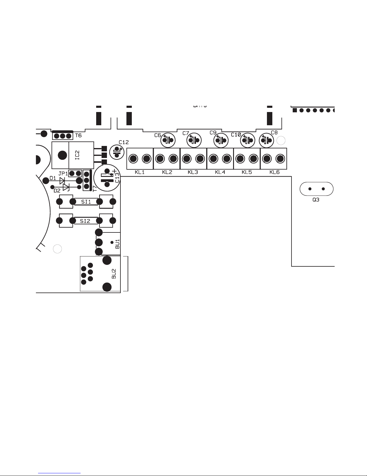
The connector lead of the DCF module is fed through the back of
the base station through square opening and placed in the BU2
sleeve until it engages.
Figure 1 shows the position of the individual connections.
Figure 1: Position of the sleeves
Page 6
14
3. Reception control and conguration
The DCF module is fitted with a connector lead and can therefore
be positioned independently of the base station. The module
should be installed at a distance of at least 0.5 m from the base
station, so that reception is not affected by the electronics of the
alarm base station.
In addition an adequate distance should be maintained to other
electrical devices, as for example televisions or electrical cables
that can also affect reception.
The DCF module incorporates an LED that monitors the reception.
The module should be positioned such that the LED illuminates
regularly every second. On the 59th second a pulse is received
indicating the start of a data packet and which should not be
interpreted as bad reception.
After the first reception pulse the base station releases the configuration menu for the DCF reception. Using the “DCF Configuration”
menu the DCF receiver can be switched manually active or passive.
It is also possible to check whether synchronisation has occurred.
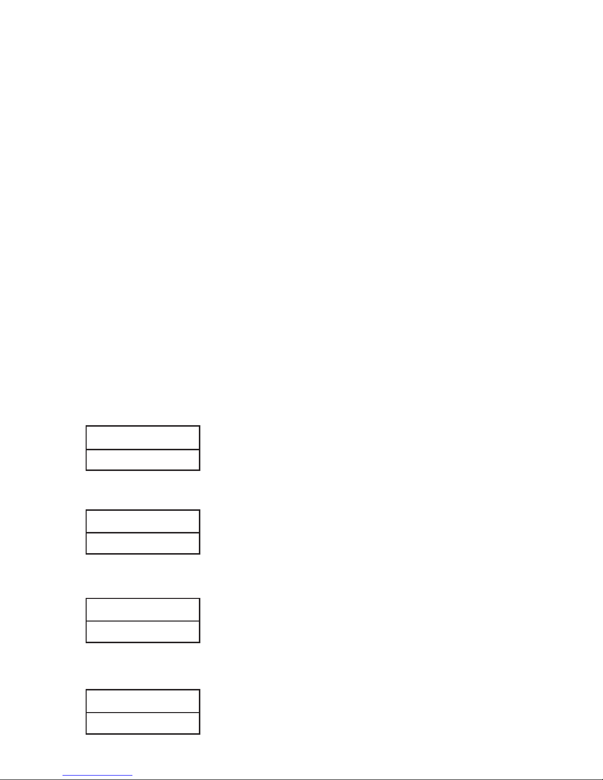
- Press the “Menu a/A” key (below left), and the following appears
troubles
- Use the “↓” and “↑” keys to select the “AZ Config” menu.
setup
- Press “OK” to access this menu, the following appears:
setup
Set time
- Use the “↓” and “↑” keys to select the “DCF Config” menu.
setup
DCF config
Page 7

15
- Press “OK” to access this menu, the following appears, for
example:
DCF activ
not synchr.
- Use the “↓” and “↑” keys to select the DCF reception manually
active or inactive.
- The lower display line shows whether synchronisation occurred
or not.
- Press “OK” to accept the changes.
- Press the “ C” to return to normal display.
After aligning the DCF receiver the following displays appear after
three minutes
DCF activ
synchron
If this is not the case then the positioning of the DCF module must
be re-checked and modified. In many cases it is sufficient to gently
turn the DCF module.
→
Page 8
16
ELV Elektronik AG • Postfach 1000 • D-26787 Leer
Tel.: +49 (0)4 91/600 888 • Fax: +49 (0)4 91/6008-244
4. FAZ 3000-DCF technical data
Operating voltage: ............................5 V from the alarm base station
Current consumption: ...............................................................10 mA
Dimensions (W x H x D): ......................................... 51 x 76 x 20 mm
5. Disposal of Waste Equipment by Users in
Private Households in the European Union
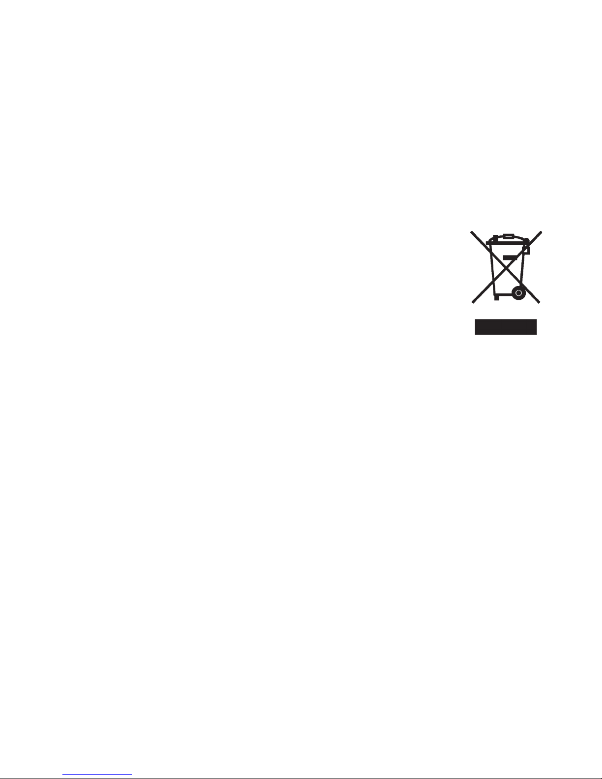
This symbol on the product or on its packaging indicates that this product must not be disposed of with
your other household waste. Instead, it is your responsibility to dispose of your waste equipment by handing
it over to a designated collection point for the recycling
of waste electrical and electronic equipment.
The separate collection and recycling of your waste
equipment at the time of disposal will help to conserve natural
resources and ensure that it is recycled in a manner that protects
human health and the environment.
 Loading...