

Page 1
Electronic thermostat
ETH eco
Opera tion an d display Gener al func tion
This electronic thermostat for radi ators can be used to
control ro om temperat ure on the basi s of time. The actu ator moves a valve, thereby allowing the a mount of heat
flowing to the he ating applia nce to be controlled. The
controlle r is co mpatible with all standard heating appl iance valves .
Insta llati on can be a chieve d in 3 easy st eps.
Step 1: Ins erti ng (replacing ) the bat teries
Remove the b atter y com-•
partme nt cover.
Insert 2 new Mignon bat-•
teri es (L R6/A A) in to the
batter y compart ment, ensuring they are the right
way round.
Reattac h the battery com-•
partme nt cover and click
into place.
New alka line bat teries have a life of approximately th ree
years. A battery symb ol (
) will indicate when the batteries nee d to be replaced. Af ter removing the ol d batteries, plea se wait appro -ximately 1 mi nute before in serting
the new ones. This device does not support operation with
recharg eable bat teries.
Never recha rge standard batte ries.
Doing so will p resent a risk of explosi on.
Do not throw the b atterie s into a fire.
Do not shor t-circui t batteries.
Used batteries should not be disposed
of with regular domestic waste. Instead,
they should be taken to your local batter y
disposal p oint.
Step 2: S etting the da te and time of day
The firmware version number will be displayed briefly once
you have inserted/rep laced the batteries and then you will be
automatic ally promp ted to set the date a nd time of day.
Use the set ting wheel ( B) to set •
the year (A).
Confirm wit h OK (C).•
Use the set ting wheel ( B) to set •
the month (A ).
Confirm wit h OK (C).•
Use the set ting wheel ( B) to set •
the day (A).
Confirm wit h OK (C).•
Use the set ting wheel ( B) to set •
the hour (A).
Confirm wit h OK (C).•
Use the set ting wheel ( B) to set •
the minute (A ).
Confirm wit h OK (C).•
The motor will star t moving back the cont rol pin while the
entries a re still bein g made.
If “IN S” is disp layed with a rotating “•
∏
” symb ol, this
indicates that the motor is still movin g back. Once the
device is ready for the actuator to be insta lled on the
valve, just “I NS” will appe ar on the disp lay.
The weekl y program and oth er sett ings can be cus-•
tomised prior to installation. To do this, press the m enu
button wh en “INS” i s shown on t he display. For furthe r
details, p lease see “4. Confi guration m enu”.
O n c e p r o g r a m m i n g i s c o m p l e t e , “ I N S ” w i l l r e a p p e a r o n t h e •
display and i nstallat ion (Step 3) ca n commenc e.
Step 3: I nstal ling th e elect ronic thermo stat
The actuato r can be in stall ed on all s tanda rd he ating
valves. There is n o need to drain away w ater or fid dle
around with the heating system befor e doin g thi s. Fir st,
you need to rem ove the old thermostat di al:
Turn the thermosta t di al anti- •
clockwi se as f ar as it will go (A).
Release the therma l ring of the •
thermos tat (B).
Remove the thermostat from •
the valve (C).
An adapte r will nee d to be use d
in the case of cer tain valv es.
Adapters for Danfos s valve s (RA, RAV, RAVL) are included in the scope of delivery. For details, please refer to the
adapter over view (see 18).
The adapte r must be plac ed •
on the valve and t urned unti l
it is secure ly seated.
In the case of the RAV a dapter, •
the extension su pplied must be
attache d to the valve tappet.
The RA a nd RAV a dapter s •
must, in addition, be secured
by me ans of th e bo lt an d nut
supplied.
The electr onic thermo stat can only be inst alled if “INS” is
showing on the display. Following installation, the actuator
will perf orm an adjus tment run so th at it can adapt to th e
valve. Durin g this proce ss, “ADA” will be displ ayed.
Place the act uator on the val ve.•
Tighten the u nion nut.•
“INS” will ap pear on the di splay, press th e OK button.•
The actuato r will perfo rm an adjust ment run (“ADA” will •
appear on t he display, oper ation not pos sible).
After that, the ac tuator will be ready for operatio n (Auto •
mode).
If the adjustment run was in itiated prior to install ation, or if an erro r message wil l be displayed (F1, F2,
F3); pres s OK to move the moto r back to the “INS”
position.
1. Setti ng the weekly pr ogram
The weekly program al lows y ou to set up to 3 sepa rate
heating periods (7 switc hing times) fo r e ach day of the
week. Programming is p erform ed in relation to the selected days , for which temp eratures m ust be stored fo r a
period fr om 00:00 to 23:59.
Pr es s a nd ho ld dow n t he me nu bu tt on fo r m or e th a n 3 s ec on ds .
“PRO” will app ear on the dis play.•
Confirm wit h OK.•
“DAY” will appear on the display. The set ting wheel can •
be used to select an ind ividual day of the week , all working days, the we ekend or the enti re week (example
shows worki ng days selec ted).
Confirm wit h OK.•
The first setting time will appear on •
the display (0:00). T his cannot be
changed. In addition, the display
shows bars for every other switching inter val.
Confirm wit h OK.•
Set the temp erature t hat is to be •
maintain ed from 0:00 onwards (example shows 17.0°C).
Confirm wit h OK.•
The next switching time appears on •
the dis play (exa mple shows 6:0 0).
Use the setting wheel to set the time.
Confirm wit h OK.•
Then, se lect a temperatu re for the •
selecte d switching tim e.
Keep repeating this process until you have finished storing •
temperat ures for the p eriod fro m 0:00 to 23:59.
After all 7 switching times have been selecte d, 23:59 will •
appear on t he display as e nd time.
Confirm wit h OK.•
In Auto mode, the temperature can be modified at any time
via the set ting wheel. The modifi ed temper ature will then
be retaine d until the next program c hangeover.
2. Week ly prog ram: Ex ample s
The electro nic th ermo stat allows you to sto re up to 3
heating periods (7 switching times) with individual temperature set tings for each day of the week. The facto ry setting con sists of two heat ing phas es (from 6:00 until 9:00
and f rom 17:00 until 23:00 respe ctively) for every single
day of the week:
From 00:00 to 06:00 17.0°C
From 06:00 to 09:00 21.0°C
From 09:00 to 17:00 17.0°C
From 17:00 to 23:00 21.0°C
From 23:00 to 23:59 17.0°C
To represent the switching periods, the display shows
bars for ever y other switching inter val. In this example, no bars are sh own for the interval from 0:0 0 to
6:00. Bar s are only show n on the display for the intervals f rom 6:00 to 9:00 a nd from 17:00 to 23:00.
If a room also needs to be heated at around noon, the correspondi ng progra m might look li ke this:
Monday to Sunday
From 00:00 to 06:00 16.0°C
From 06:00 to 09:00 22.0°C
From 09:00 to 12:00 17.0°C
From 12:00 to 14:00 20.0°C
From 14:00 to 17:30 17.0°C
From 17:30 to 23:30 21.0°C
From 23:30 to 23:59 16.0°C
If you have a hom e office a nd on ly wan t it to be hea ted
during the day on working days , you can program the following time s:
Monday to Friday
From 00:00 to 08:30 17.0°C
From 08:30 to 17:00 21.0°C
From 17:00 to 23:59 17.0°C
Saturday and Sunday
From 00:00 to 23:59 15.0°C
3. Oper ating modes
To s wit ch be twe en the 3 o pe rat in g mo de s d esc ri be d b elo w,
press the men u button bri efly (these ope rating modes can
only be sele cted following instal lation/S tep 3):
Holida y function• ( ): Set a temp erature th at is to be
maintain ed until a fixed p oint in time.
Manu: • Manual operation – The te mperature is se t manu-
ally using t he setting w heel.
Auto: • We e k l y p r o g r a m – T h e t e m p e r a t u r e i s c o n t r o l l e d a u to -
maticall y in accorda nce with the stored week ly progra m.
Please read th is manual ca refully in ord er to help you put
the device into op eration. Kee p the manual han dy so you
can refer to it a t a later date!
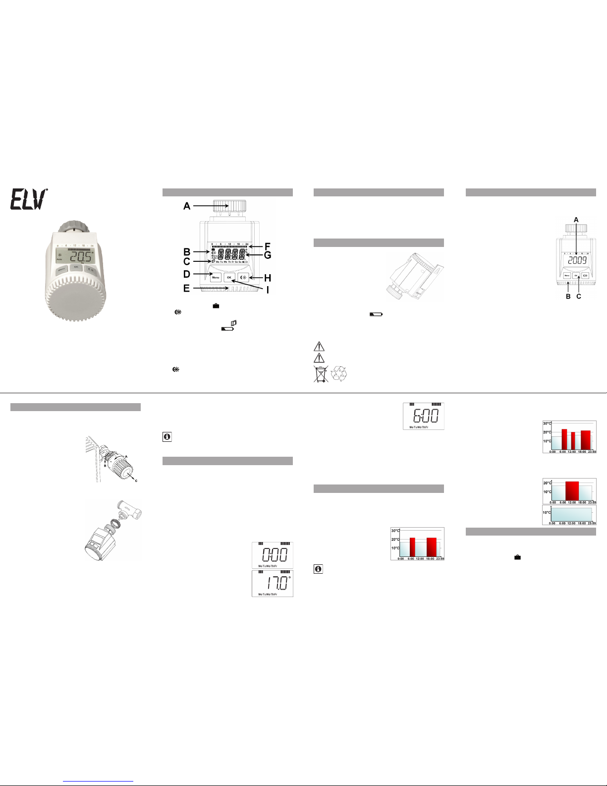
A Thermal rin g
B Holiday function (
), set-b ack/comf ort temperatur e
(
), manual oper ation (Manu), automatic oper ation
(Auto)
C “Window open” symbol (
), day of the we ek, “bat-
tery empt y” symbol (
)
D Menu but ton: Press and hold down the button for more
than 3 seco nds to open the c onfigurat ion menu
E Set ting wheel: For making adjustme nts (e.g. temperature)
F Switchin g period s set within we ekly progr am
G Current temper ature setting , time and date indicator,
menu items , function s
H
bu tt on: For sw itc hi ng b et we en s et- ba ck a nd co m-
fort temp erature s
I OK button: For c onfirming/saving
5
2
6
3
7
4
8
ELV Elekt ronik AG · P.O.Box 1000 · D-26 787 Leer
Page 2
4. Config uration men u
The configuration menu can be used to modify settings.
To ac cess t his m enu, press and hold down the m enu
button (for more than 3 seconds).
PRO: For setting the wee kly program (s ee Section “1 •
Setting th e weekly pr ogram”)
DAT: For modifying the time o f day and date•
POS: For quer ying the actuator’s curre nt position•
DST: Automati c switchover at the start or end of daylight •
saving time c an be deact ivated.
AER: For s etting the “window op en” temperatu re and •
time s o tha t the temperature is automatica lly re duced
in the event of ven tilation
TOF: For settin g the offse t temperat ure•
RES: For restor ing the factory sett ings•
Use the setting wheel to select menu items and the OK button to confirm your choice. Press the menu button again to
return to the previous level. After 65 seconds without anything happening, the menu will close automatically.
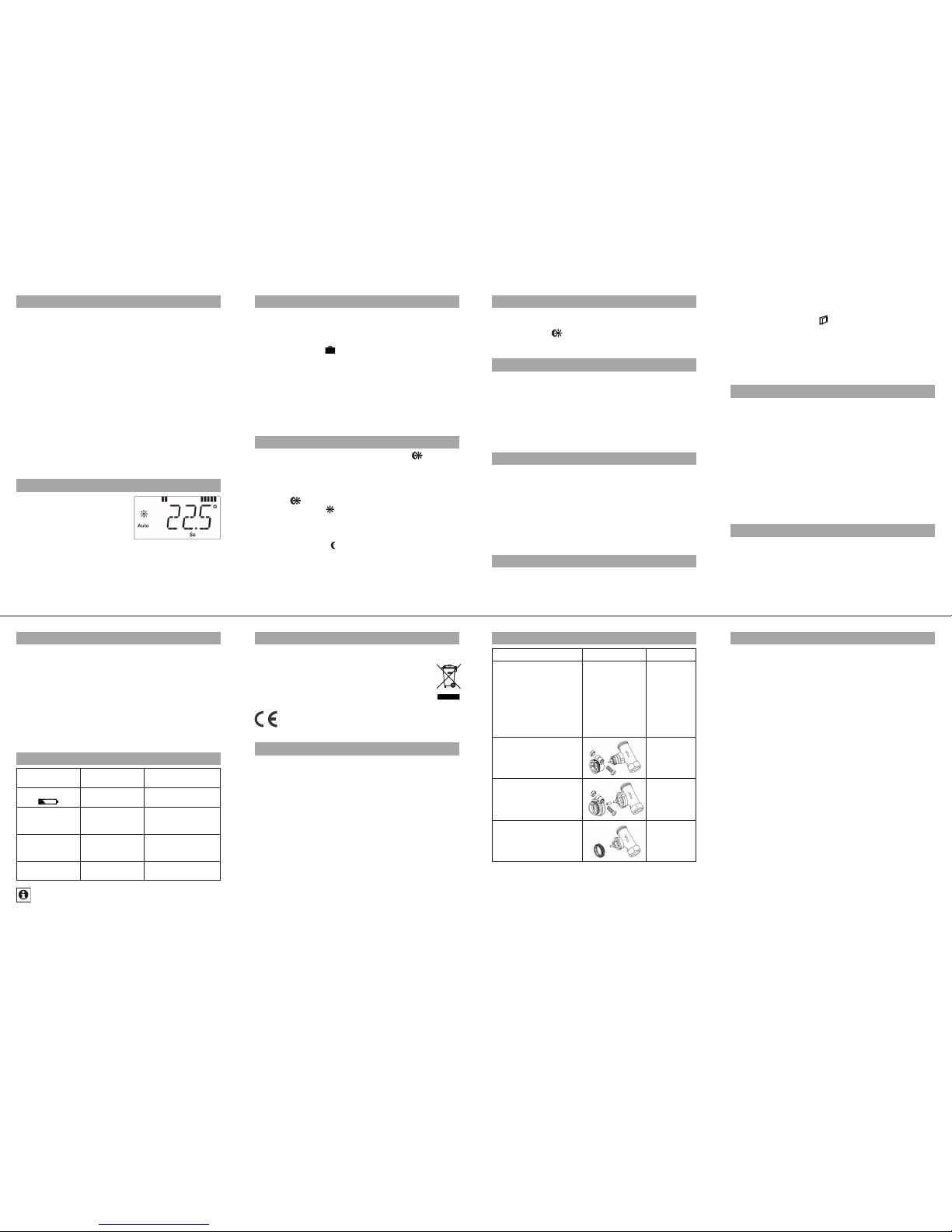
5. Disp lay content dur ing normal ope ratio n
Du rin g no rma l op er ati on,
the foll owin g are displa yed:
switchi ng per iods, opera ting
mod e, temp erat ure s et tin g
and day of the wee k.
The bars i ndicatin g the weekly program’s switc hing perio ds are shown for every other
time inte rval. Fo r an example, p lease refer to “2. Weekly
program: E xamples”.
6. Sett ing the holid ay funct ion
If you want a fixed tempera ture to be maintain ed for a set
period of time while you are on ho liday or du ring a par ty,
you can make us e of the Holiday f unction.
Press and re lease the me nu button repeatedly u ntil the •
suitcase sy mbol (
) appears on the disp lay.
Use the se tting wh eel to se t the end of the time period •
during whi ch the tempe rature is to be m aintaine d.
Press the OK b utton to con firm.•
Then use th e setting wh eel to set the d ate.•
Press the OK b utton to con firm.•
Use the se tting wheel to set the temperature; press OK to •
confirm. Th e display wil l flash to confir m your settings.
The set temperature will remain in force until the specified
time. Afte r that, the act uator will ado pt Auto mode.
7. Comfort a nd set-ba ck temperatu res
The comfo rt/set- back tempe rature bu tton (
) provides
an easy a nd conveni ent way of switching between these
two temperatures. The factory settings are 21.0°C and
17.0°C respe ctively. To adapt them, p roceed a s follows:
Press and hold down the c omfort /set-back temper ature •
button (
) for more than 3 second s.
The sun symbol ( •
) will a ppear on the display along
with the cur rent comfo rt tempe rature.
Use the settin g wheel to modif y the tempera ture; press •
OK to confirm.
The moon symbo l ( •
) will appea r together with the setback tempe rature.
Use the settin g wheel to modif y the tempera ture; press •
OK to confirm.
The temperature can even be modified in Auto mode at any
time by using this button. The new settin g will be retained
until the pro gram’s next switc hing time.
8. Chil d-pro of lock /Operating in hibit
Operati on can be inhi bited.
To activate/dea ctivate the operating inhibit, briefly press •
the Menu and
buttons at t he same time .
Once the fu nction is active, “LOC ” will appe ar on the dis play.•
To deactivate the fu nction, pre ss both buttons again .•
9. Sett ing the heati ng break
If the heating is being switched off for the summer, you can
save battery power. This involves op ening the valve up fully.
Limesca le protecti on measur es remain i n place.
To ac tivate the heating break, turn the setting wheel •
clockwi se d uring manual oper ation (Manu) until “ ON”
appear s on the displa y.
To terminate the heating break, quit manual ope ration •
(Manu) or turn the se tting whe el anticlo ckwise.
10. Sett ing frost prote ction mode
If you do not want the room to be hea ted, the valve can
be closed. It will only be o pened ag ain if there i s a risk of
freezing due to fro st. Lime scale pr otection m easures remain in plac e.
To activate frost protect ion mode, turn the setting wheel •
anticlockwise during m anual operation (Manu) until “OFF”
appear s on the display.
To terminate frost prote ction mode, quit manual oper a-•
tion (Manu) o r turn the set ting wheel clockwi se.
11. “Window op en” func tion
In the event of a significant drop in temperatu re, the actuator can automatically detect w hether the room is being
ventilated. To save on heating costs , the temperature is
th en a ut oma ti ca lly re duc ed for a s pec ifi c ti me per io d (f ac tory sett ing: 15 minutes). While thi s function is ac tive, the
“window ope n” symbol (
) appears on the disp lay.
Press and hol d d own the menu button for more than •
3 seconds .
Use the set ting wheel to s elect the “AER” m enu item.•
Confirm wit h OK.•
Use the se tting wh eel to set the tempe rature an d time. •
To deactivate the fu nction, sel ect a time of “ 0”.
12. Set ting th e offset tempe rature
The temperature is measured at the heating appliance
itself, wit h the resu lt that ot her par ts of the r oom may be
warmer o r colder than this. To allow for this, you can set
a temper ature of fset of ±3 .5°C. If, for ex ample, a te mperature of 18°C is measured somewhere within th e roo m
instead o f the 20°C set, it m eans tha t an off set of -2.0°C
needs to be c onfigured.
Press and hol d d own the menu button for more than •
3 seconds .
Use the set ting wheel to s elect the “ TOF” menu item .•
Confirm wit h OK.•
Use the set ting wheel to m odify the te mperature.•
Press the OK b utton to con firm.•
13. Resto ring th e factor y settings
You can reset the actuator to its initial state manually. This
will clear a ll the setti ngs that have be en made manually.
Press and hol d d own the menu button for more than •
3 seconds .
Use the set ting wheel to s elect the “ RES” menu ite m.•
Confirm wit h OK.•
“CFM” will app ear on the display; pres s OK to confirm.•
14. Intend ed use
The elec troni c the rmostat has b een designe d for the
purpose of controlling a standar d heatin g applia nce valve. Th e devi ce m ay onl y be operated i ndoors and must
be prote cted fr om the effects of damp and dust, as well
as solar ra diation and s ources of radiant hea t.
Using the dev ice for a purpose or in a manner oth er than
that desc ribe d in th is op erating manua l constitu tes a
breach of the “inten ded use” and shall inval idate the warranty and a ny liabilit y claims. Th e same shall a pply in the
event of any c onversion or modificatio n work. The devices
are intende d exclusively for domest ic use.
15. Trouble shooti ng and mainten ance
Error c ode on
displ ay
Problem Remedy
Batter y symbol
(
)
Batter y power
too low
Replace b atterie s
F1
Valve actuato r
sluggish
Check ins tallatio n,
inspect h eating
valve
F2
Adjustin g range
too large
Check
actuator
fastening
F3
Adjustin g range
too small
Check hea ting
valve
At 12:00 every Saturday, the actuator perfor ms a
weekly desc aling functio n to prevent valve calcifica tion. “CAL” will appear o n the display.
16. Inst ructi ons for disposa l
Do n ot d ispos e of the de vice with reg ular dom estic
waste.
Electronic equipment must be disposed of at local
collection points for waste electronic equipment in
complian ce with local directive s governing waste
electri cal and ele ctronic e quipment .
The CE sign is a free trade sign ad dressed exclusively to the authorit ies and does not warr ant
any proper ties.
17. Safety ins truct ions
The device s concern ed are not inten ded for chil dren and
must not be used as toys. Do not leave packaging material lying around, as chi ldren might be temp ted to play with
it, which is extremel y dangerous. Do not open the device:
it does n ot contai n any comp onents th at need to be serviced by the user. In the event of an error, pl ease r eturn
the device to ou r servic e department.
Issue 1 Eng lish 02/2010
Documen tation © 2010 ELV Elektronik AG
All right s reserved.
90669, V1.2, w ww.elv.com
19. Technica l propertie s
Supply volt age: 3 V
Max. current consumption:
100 mA
Batteri es: 2x Mignon ba tteries ( LR6/AA)
Batter y life: Approx. 3 yea rs
Display: LC disp lay
Housing di mensions: 63 x 66 x 92 mm ( W x H x D)
Connect ion: M30 x 1.5
We reser ve the right to mak e any tech nical c hange s
that co nstit ute an improvem ent to th e device .
9
13
10
14
11
15
12
16
18. Adap ter over view
Manufacturer Figure Adapter
Heimeier, MNG , Jun-
kers, Lan dis&Gyr
“Duodyr ”, Honeywell-
Braukma nn, Oventrop,
Schlöss er, Simplex,
Valf Sanayii, M ertik
Maxitro l, Watts,
Wingenro th (Wirofl ex),
R.B.M., Tie mme, Jaga
No adapter
required
Danfoss R A
Included
in scope of
supply
Danfoss R AV
Included
in scope of
supply
Danfoss R AVL
Included
in scope of
supply
Other a dapters avail able as access ories .
 Loading...