

Page 1
1
Bedienungsanleitung
Operating Manual
ETH comfort300
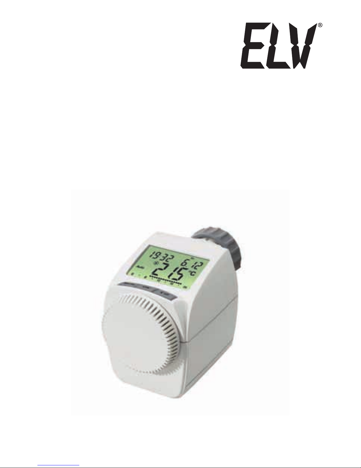
Funk-Elektronik-Thermostat
für Heizkörper (S. 2)
Radio electronic thermostat
for radiators (p. 20)
Bedienungsanleitung
ELV Elektronik AG · PF 1000 · D-26787 Leer
Page 2

2
Inhaltsverzeichnis
1. Bedienung und Display ................................................3
2. Bestimmungsgemäßer Einsatz ....................................4
3. Sicherheitshinweis .......................................................4
4. Entsorgungshinweis .....................................................4
5. Allgemeine Funktion ....................................................5
6. (Schritt 1) Batterien einlegen (wechseln)......................5
7. (Schritt 2) Datum und Uhrzeit einstellen ......................6
8. (Schritt 3) Energiespar-Regler montieren .....................7
9. (Schritt 4) Diebstahl-/Sabotageschutz montieren ........8
10. Wochenprogramm einstellen .......................................9
11. Wochenprogramm: Beispiele .....................................10
12. Betriebsmodi .............................................................11
13. Konfigurationsmenü ...................................................11
14. Display-Inhalt im Normalbetrieb ................................12
15. Anlernen von Funkkomponenten ...............................12
16. Ablernen von Funkkomponenten...............................12
17. Betrieb mit Wandthermostat .....................................13
18. Urlaubsfunktion einstellen .........................................13
19. Komfort- und Absenktemperatur ...............................14
20. Kindersicherung/Bediensperre ..................................14
21. Heizpause einstellen ..................................................14
22. Frostschutzbetrieb einstellen .....................................15
23. Fenster-auf-Funktion .................................................15
24. Offset-Temperatur einstellen......................................16
25. Werkseinstellungen wieder herstellen........................16
26. Fehlerbehebung und Wartung ...................................17
27. Adapterübersicht .......................................................18
28. Hinweise zum Funkbetrieb ........................................19
29. Technische Eigenschaften .........................................19
Lesen Sie diese Anleitung sorgfältig, um das Gerät in Betrieb zu nehmen. Bewahren Sie die Anleitung zum späteren Nachschlagen auf.
1. Ausgabe Deutsch 08/2010
Dokumentation © 2010 ELV Elektronik AG.
Alle Rechte vorbehalten.
92311, V1.0, www.elv.com
Page 3
3
A
B
C
D
E
F
G
H
I
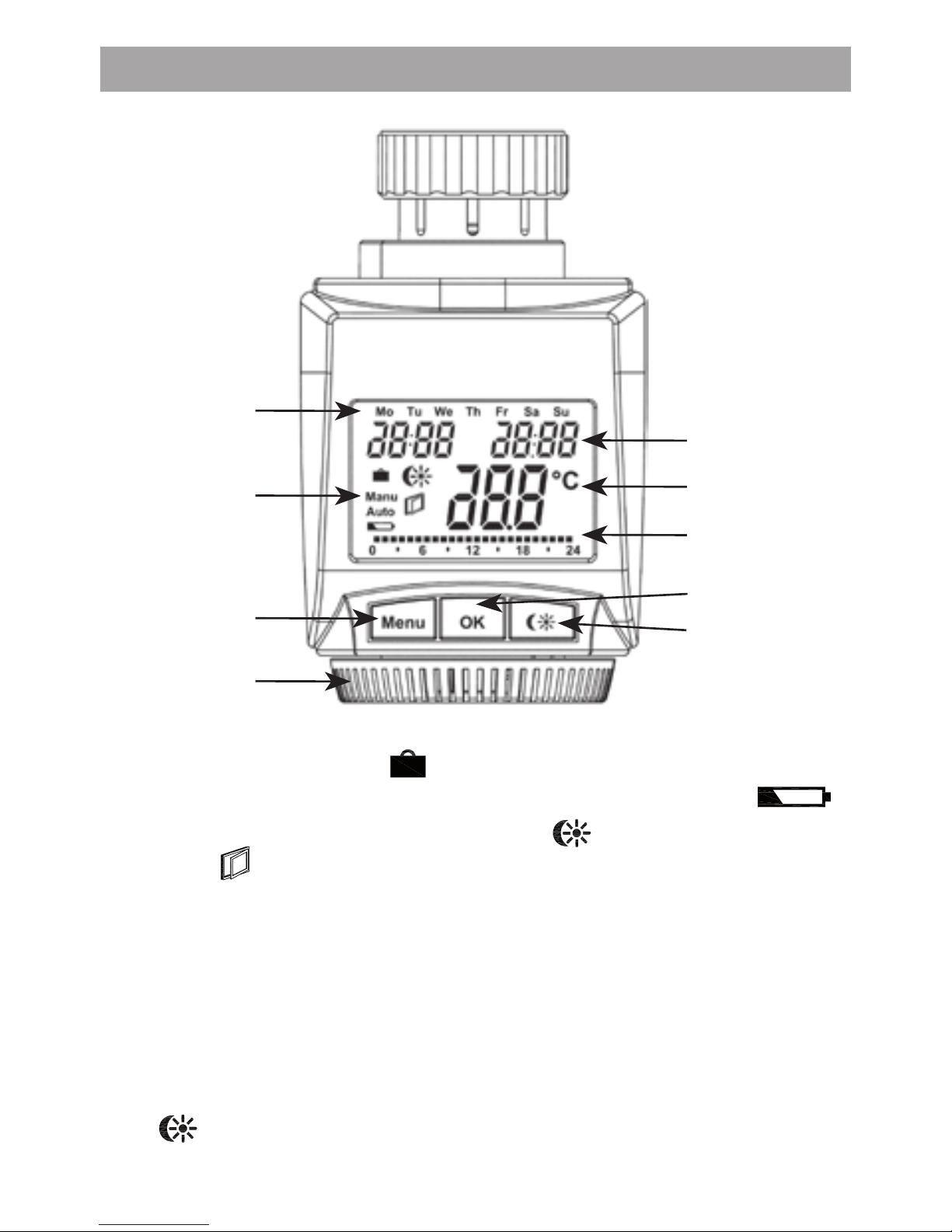
1. Bedienung und Display
A Wochentag
B Urlaubsfunktion (
), Manueller Betrieb (Manu), Au-
tomatikbetrieb (Auto), Batterie-leer-Symbol (
),
Absenk-/Komforttemperatur (
), Fenster-auf-Sym-
bol (
)
C Menü-Taste: Taste länger als 3 Sekunden drücken zum
Öffnen des Konfigurationsmenüs
D Stellrad: Einstellungen vornehmen (z. B. Temperatur)
E Zeit- und Datumsanzeige, Menüpunkte, Funktionen
F Temperaturanzeige, aktuelle Solltemperatur
G eingestellte Schaltzeiträume im Wochenprogramm
H OK-Taste: zum Bestätigen/Speichern, Anlernen
I
-Taste: Umschalten zwischen Absenk- und Kom-
forttemperatur
Page 4

4
2. Bestimmungsgemäßer Einsatz
Der Energiespar-Regler dient zum Regulieren eines gängigen Heizkörper ventils. Betreiben Sie das Gerät nur in Innenräumen und vermeiden Sie den Einfluss von Feuchtigkeit, Staub sowie Sonnen- oder Wärmebestrahlung.
Jeder andere Einsatz als in dieser Bedienungsanleitung
beschrieben ist nicht bestimmungsgemäß und führt zu
Garantie- und Haftungsausschluss. Dies gilt auch für Umbauten und Veränderungen. Die Geräte sind ausschließlich
für den privaten Gebrauch gedacht.
3. Sicherheitshinweise
Die Geräte sind keine Spielzeuge, erlauben Sie Kindern
nicht damit zu spielen. Verpackungsmaterial nicht achtlos
liegen lassen, dies kann für Kinder zu einem gefährlichen
Spielzeug werden. Öffnen Sie das Gerät nicht, es enthält
keine durch den Anwender zu wartenden Teile. Im Fehlerfall schicken Sie das Gerät an den Service.
4. Entsorgungshinweis
Gerät nicht im Hausmüll entsorgen!
Elektronische Geräte sind entsprechend der
Richtlinie über Elektro- und Elektronik-Altgeräte
über die örtlichen Sammelstellen für ElektronikAltgeräte zu entsorgen!
Das CE-Zeichen ist ein Freiverkehrszeichen, das
sich ausschließlich an die Behörden wendet und
keine Zusicherung von Eigenschaften beinhaltet.
Page 5
5
5. Allgemeine Funktion
Der Energiespar-Regler für Heizkörper regelt zeitgesteuert
die Raumtemperatur. Der Stellantrieb bewegt ein Ventil, um
den Wärmezustrom am Heizkörper zu steuern. Der Regler passt auf alle gängigen Heizkörperventile. Das große
beleuchtete Display dient zur komfortablen Bedienung.
Über einen Funkempfänger kann das Gerät Befehle von
angelernten Systemkomponenten empfangen. Durch die
Verwendung von Baby-Zellen wird eine Wartung nahezu
unnötig. Der Sabotage- und Diebstahlschutz verhindert
ein unbefugtes Demontieren.
Die Montage erfolgt in 4 einfachen Schritten.
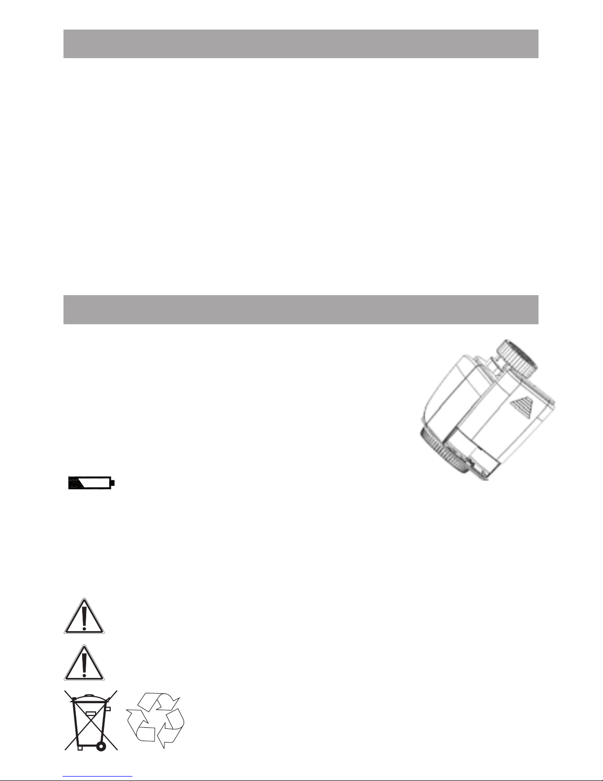
6. (Schritt 1) Batterien einlegen (wechseln)
Batte• riefachdeckel abziehen
2 neue LR14-Batterien (Baby/C) pol-•
ungsrichtig in das Batteriefach einlegen
Batteriefachdeckel wieder aufsetzen •
und einrasten
Die Lebensdauer neuer Alkali-Batterien
beträgt ca. fünf Jahre. Ein Batteriesymbol
(
) weist darauf hin, dass die Batterien auszutauschen sind. Vor dem Wechseln der Batterien
muss der Diebstahl-/Sabotageschutz demontiert werden.
Nach Entnahme der Batterien sollte bis zum Einlegen der
neuen Batterien ca. 1 Minute gewartet werden. Ein Betrieb
mit Akkus ist nicht möglich.
Normale Batterien dürfen niemals aufgeladen
werden. Es besteht Explosionsgefahr.
Batterien nicht ins Feuer werfen!
Batterien nicht kurzschließen!
Verbrauchte Batterien gehören nicht in
den Hausmüll! Entsorgen Sie diese in
Ihrer örtlichen Batteriesammelstelle!
Page 6
6
A
C
B
D
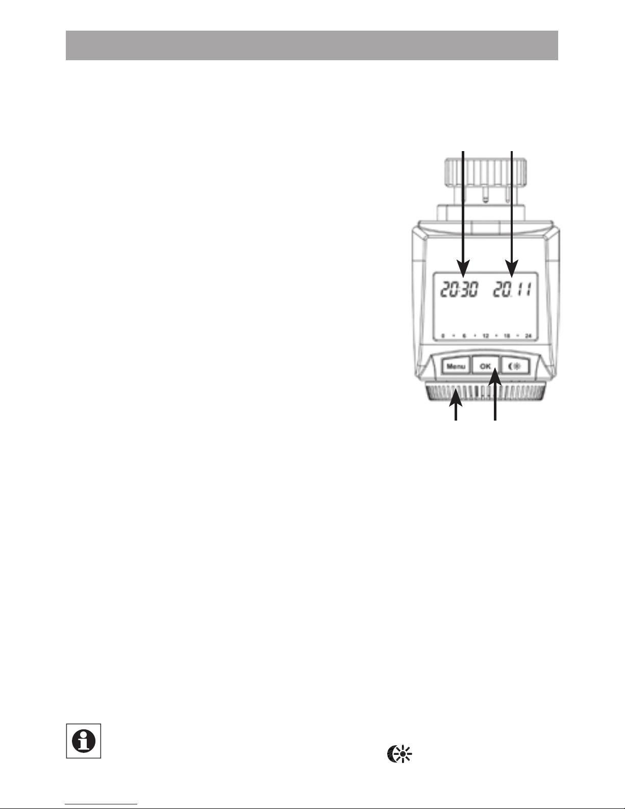
7. (Schritt 2) Datum und Uhrzeit einstellen
Wenn Batterien eingelegt oder ausgetauscht werden, wird
nach kurzer Anzeige der Firmware-Versionsnummer automatisch Datum und Uhrzeit abgefragt.
Jahr (B) mit Stellrad (C) einstellen•
Mit OK (D) bestätigen•
Monat (B) mit Stellrad (C) einstellen•
Mit OK (D) bestätigen•
Tag (B) mit Stellrad (C) einstellen•
Mit OK (D) bestätigen•
Stunde (A) mit Stellrad (C) einstellen•
Mit OK (D) bestätigen•
Minute (A) mit Stellrad (C) einstellen•
Mit OK (D) bestätigen•
Während der Eingaben fährt der Motor den Steuerstift
bereits zurück.
Die Anzeige „InS“ mit drehendem „•
∏
“ weist darauf
hin, dass der Motor noch zurückfährt. Sobald der Stellantrieb am Ventil montiert werden kann, steht nur „InS“
im Display.
Das Wochenprogramm und andere Einstellungen •
können vor der Montage angepasst werden. Drücken
Sie dazu die Menü-Taste, während in der Anzeige „InS“
steht. Mehr Details finden Sie unter „13. Konfigurationsmenü“.
Nach abgeschlossener Programmierung steht erneut „InS“ •
im Display und die Montage (Schritt 3) kann erfolgen.
Während „InS“ im Display steht, kann bereits vor der
Montage durch kurzen Druck der
-Taste die Anlern-
funktion aktiviert werden.
Page 7
7
8. (Schritt 3) Energiespar-Regler montieren
Der Stellantrieb kann auf alle gängigen Heizungsventile
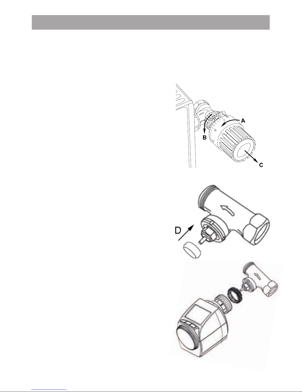
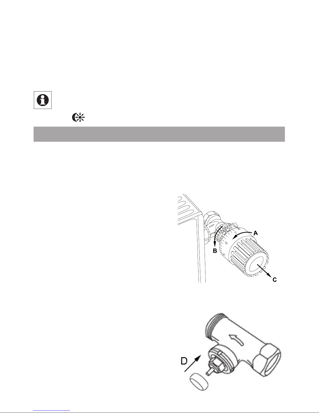
montiert werden. Ein Ablassen von Wasser oder ein Eingriff ins Heizungssystem sind dabei nicht notwendig. Zuerst ist der alte Thermostatkopf zu entfernen:
Thermostatkopf bis zum End- •
anschlag nach links drehen (A)
Befestigung des Thermos-•
tatkopfes lösen (B)
Thermostatkopf vom Ventil •
abziehen (C)
Der beiliegende Stützring dient
bei kleinen Ventilanschlüssen
zur stabileren Befestigung des
Energiespar-Reglers.
• Stecken Sie den Stützring auf
den Ventilanschluss (D) auf. Ist
der Ventilanschluss so groß,
dass der Stützring nicht aufgesteckt werden kann, ist die
Stabilität ausreichend und der
Stützring wird nicht benötigt.
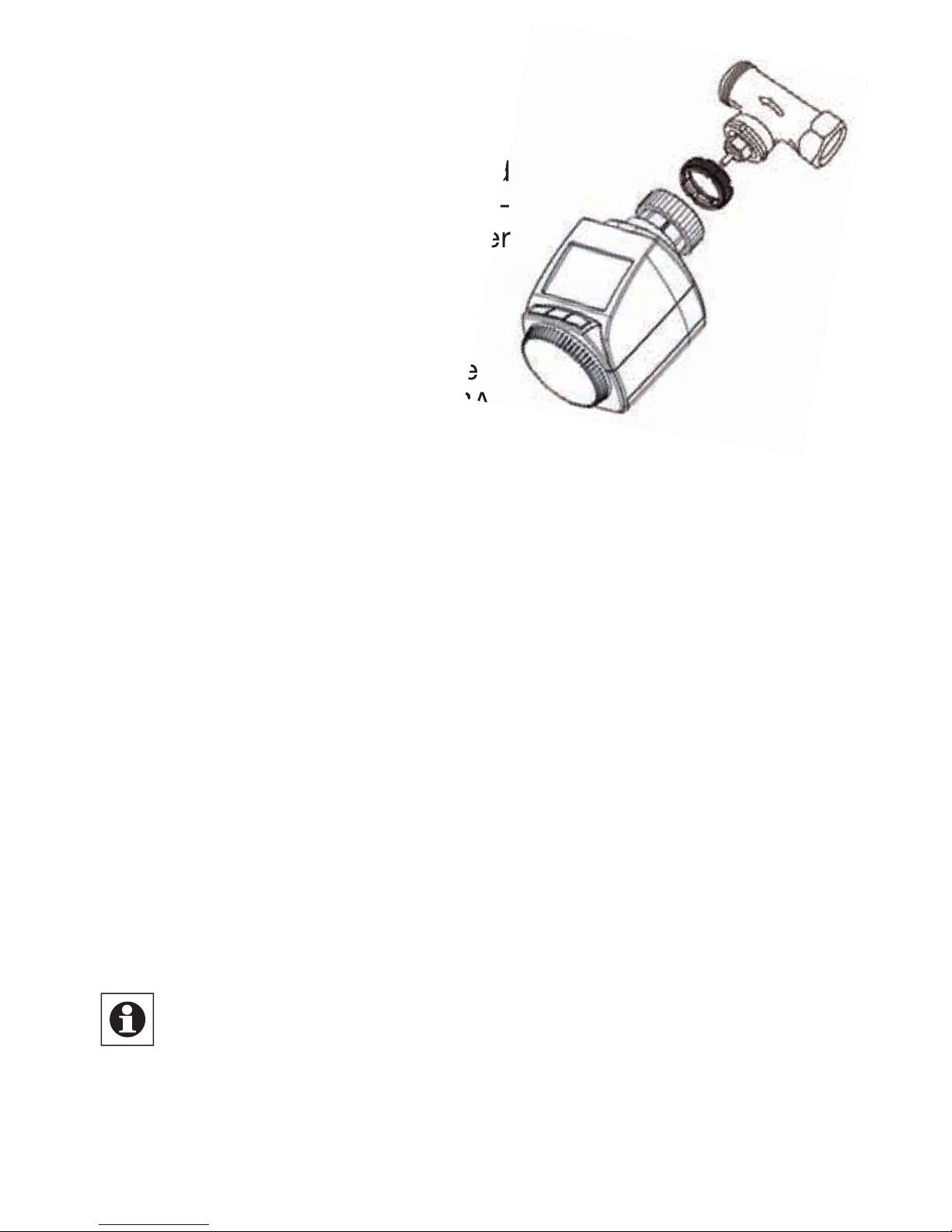
Für einige Ventile ist ein Adapter zu verwenden. Adapter
für Danfoss-Ventile (RA, RAV,
RAVL) liegen bei. Details bitte
der Adapterübersicht (siehe 27)
entnehmen.
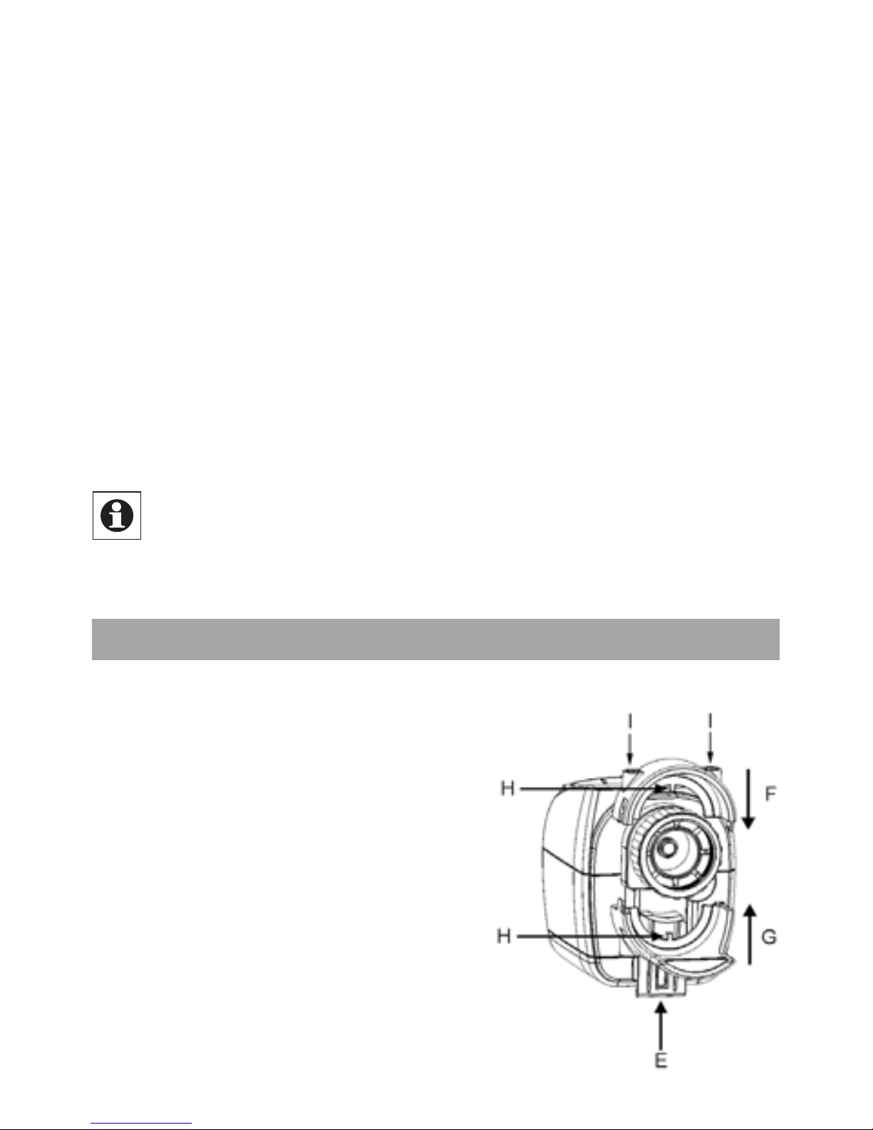
Der Adapter ist vollständig auf •
das Ventil aufzurasten. Um
die Adapter RA und RAV weit
genug auseinanderbiegen zu
können, muss ggf. ein Schraubendreher verwendet werden.
Page 8
8
Beim RAV Adapter ist die mitgelieferte Verlängerung •
auf den Ventilstößel zu stecken.
Die Adapter RA und RAV sind zusätzlich mit der mit-•
gelieferten Schraube und Mutter zu befestigen.
Damit der Energiespar-Regler montiert werden kann, muss
im Display „InS“ stehen. Nach der Montage führ t der Stellantrieb zur Anpassung ans Ventil eine Adaptierfahrt durch.
Währenddessen wird „AdA“ angezeigt.
Stellantrieb auf Ventil setzen•
Überwurfmutter festziehen•
Im Display steht „InS“, OK-Taste drücken•
Der Stellantrieb führt eine Adaptierfahrt durch (im Display •
erscheint „AdA“, keine Bedienung möglich).
Danach ist der Stellantrieb betriebsbereit (Auto-Modus)•
Wurde die Adaptierfahrt vor der Montage eingeleitet
bzw. wird eine Fehlermeldung (F1, F2, F3) angezeigt,
drücken Sie OK und der Motor fährt zurück zur Position „InS“.
9. (Schritt 4) Diebstahl-/Sabotageschutz montieren
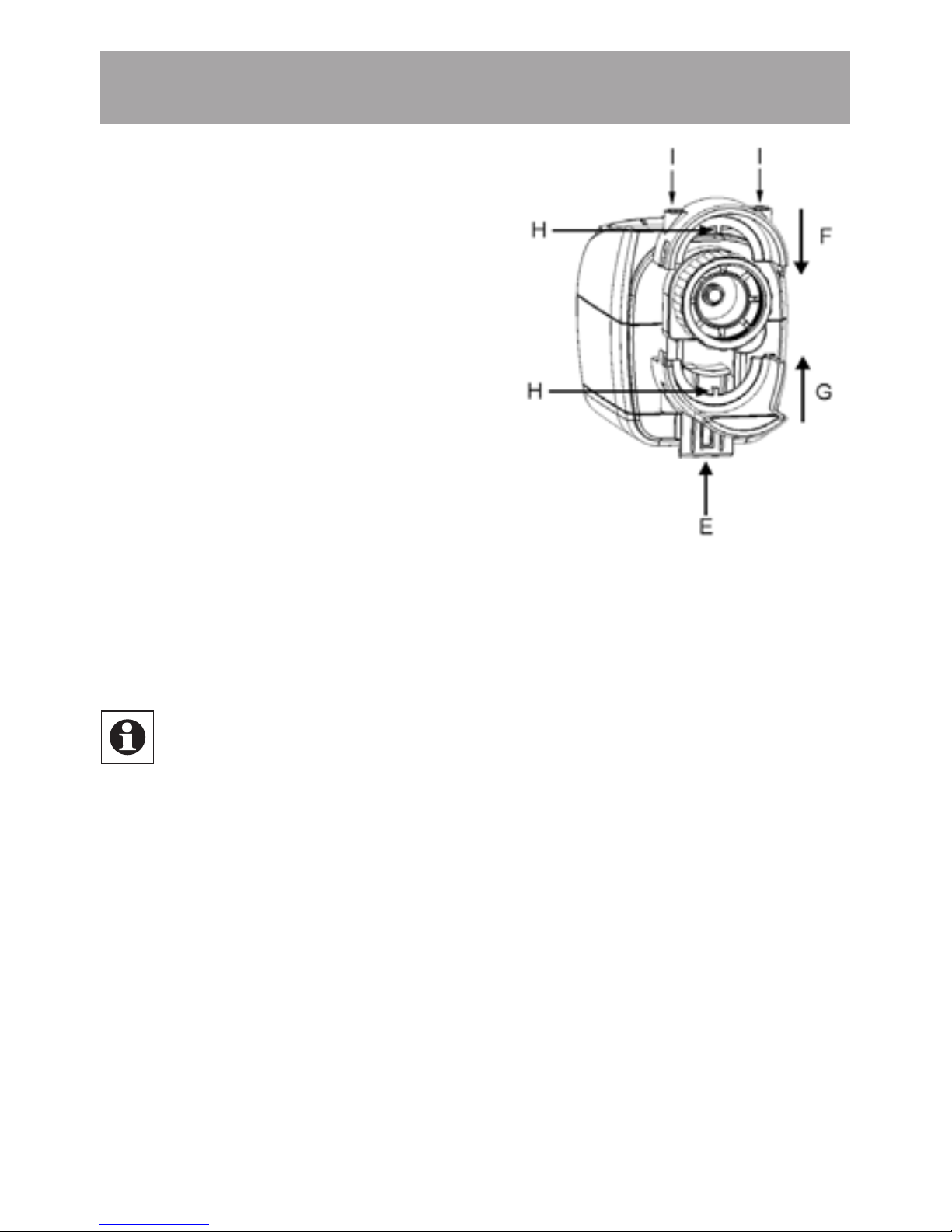
Der Diebstahl-/Sabotageschutz
verhindert das einfache Abbauen
und Stehlen des Funk-Energiespar-Reglers und der Batterien.
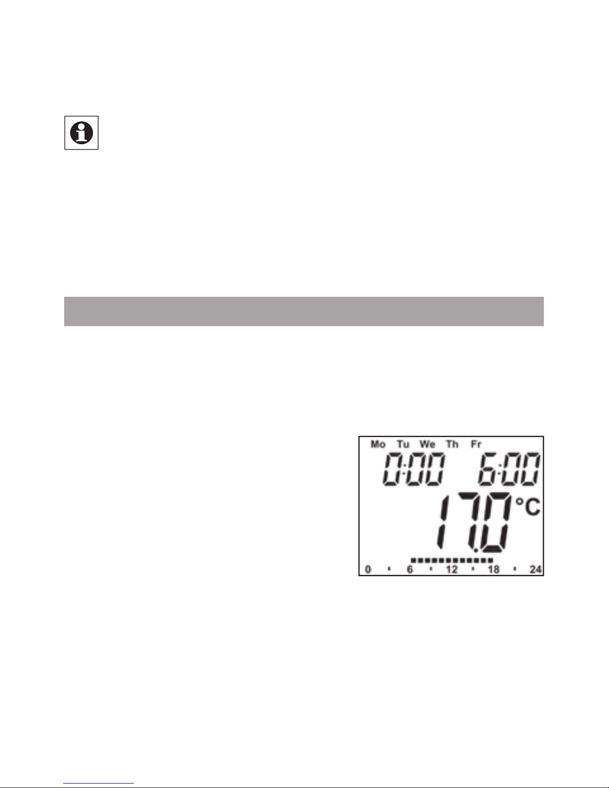
• Sabotageschutz von unten in
die Führung schieben und einrasten lassen (E). Hiermit wird
das Öffnen des Batteriefachs
verhindert.
• Ober- (F) und Unterschale (G)
auf die Überwurfmutter stecken
und einrasten lassen. Die Stege
(H) der Schalen müssen in die
Page 9
9
Zwischenräume des Flansches greifen.
• M3-Innensechskantschrauben einführen (I) und an der
Gegenseite mit Muttern befestigen.
Die Ober- und Unterschale können in beliebigen Positionen montiert werden.
Die etwas längere Unterschale hat die Aufgabe, das
Abdrehen des Funk-Energiespar-Reglers zu verhindern. Sie ist so lang, dass sie beim Drehen des Anschlusses gegen das Ventil stößt.
Die Unterschale sollte so angebracht sein, dass sie
bei einem versuchten Losdrehen des Reglers möglichst bald blockiert.
10. Wochenprogramm einstellen
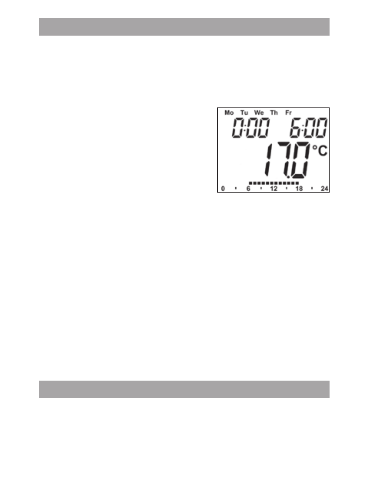
Im Wochenprogramm lassen sich für jeden Wochentag separat bis zu 3 Heizphasen (7 Schaltzeitpunkte) einstellen.
Die Programmierung erfolgt für die ausgewählten Tage,
wobei für einen Zeitraum von 00:00 bis 23:59 Temperaturen
hinterlegt werden müssen.
Menü-Taste länger als 3 Sekun-•
den drücken
Im Display erscheint „Pro“.•
Mit OK-Taste bestätigen•
Im Display erscheint „dAy“. Mit •
dem Stellrad sind ein einzelner Wochentag, alle Werktage,
das Wochenende oder die gesamte Woche auswählbar
(Bsp. Werktage).
Mit OK-Taste bestätigen•
Mit dem Stellrad den ersten Zeitabschnitt einstellen •
(Bsp. 0:00 bis 6:00).
Mit OK bestätigen•
Danach ist für den ausgewählten Zeitabschnitt die ge-•
wünschte Temperatur auszuwählen (Bsp. 17.0°C).
Page 10
10
Mit OK bestätigen•
Dieser Vorgang ist zu wiederholen, bis für den Zeitraum •
von 0:00 bis 23:59 Temperaturen hinterlegt sind.
Im Auto-Modus kann die Temperatur über das Stellrad jederzeit verändert werden. Die geänderte Temperatur bleibt
dann bis zum nächsten Programmwechsel erhalten.
11. Wochenprogramm: Beispiele
Mit dem Energiespar-Regler können für jeden Wochentag
bis zu 3 Heizzeiten (7 Schaltzeitpunkte) mit individueller
Temperaturvorgabe hinterlegt werden. Werkseitig sind
zwei Heizphasen von 6:00 bis 9:00 Uhr und von 17:00 bis
23:00 Uhr für alle Wochentage gleich hinterlegt:
ab 00:00 bis 06:00 17.0°C
ab 06:00 bis 09:00 21.0°C
ab 09:00 bis 17:00 17.0°C
ab 17:00 bis 23:00 21.0°C
ab 23:00 bis 23:59 17.0°C
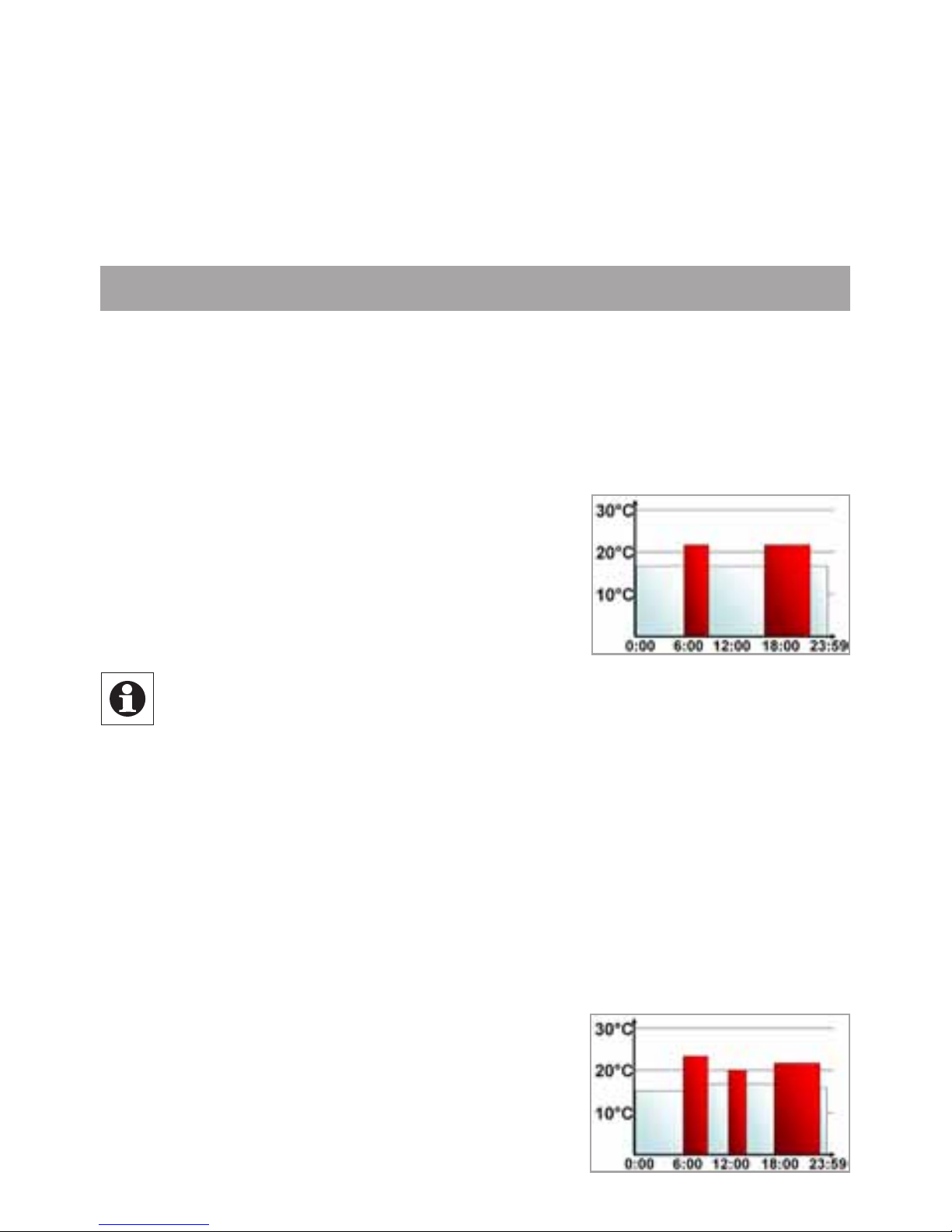
Im Display werden Balken für Zeitschalträume für jedes zweite Zeitintervall angezeigt. Bei diesem Beispiel werden keine Balken für das Intervall 0:00 bis
6:00 eingeblendet. Nur für die Intervalle 6:00 bis 9:00
und 17:00 bis 23:00 erscheinen Balken im Display.
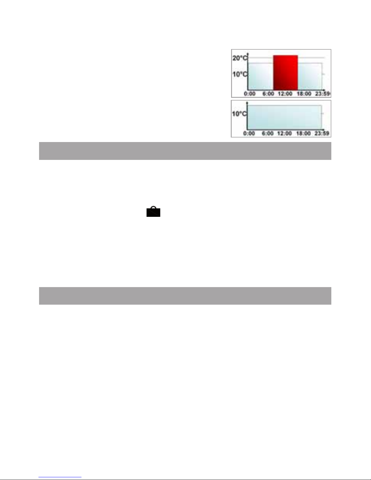
Soll ein Raum auch zur Mittagszeit beheizt werden, kann
eine Programmierung wie folgt aussehen:
Montag bis Sonntag
ab 00:00 bis 06:00 16.0°C
ab 06:00 bis 09:00 22.0°C
ab 09:00 bis 12:00 17.0°C
ab 12:00 bis 14:00 20.0°C
ab 14:00 bis 17:30 17.0°C
ab 17:30 bis 23:30 21.0°C
ab 23:30 bis 23:59 16.0°C
Page 11
11
Haben Sie zu Hause ein Büro und möchten dies nur tagsüber an Werktagen heizen, könnten Sie die folgenden Zeiten programmieren:
Montag bis Freitag
ab 00:00 bis 08:30 17.0°C
ab 08:30 bis 17:00 21.0°C
ab 17:00 bis 23:59 17.0°C
Samstag bis Sonntag
ab 00:00 bis 23:59 15.0°C
12. Betriebs-Modi
Mit kurzem Druck der Menü-Taste kann zwischen den folgenden 3 Betriebsmodi gewechselt werden (die BetriebsModi sind erst nach der Installation/Schritt 3 auswählbar):
Urlaubsfunktion• ( ) : Einstellen einer Temperatur, die
bis zu einem fixen Zeitpunkt gehalten werden soll.
Manu: • Manueller Betrieb - die Temperatur wird manuell
über das Stellrad eingestellt
Auto: • Wochenprogramm - automatische Temperaturre-
gelung gemäß hinterlegtem Wochenprogramm
13. Konfigurationsmenü
Im Konfigurationsmenü lassen sich Einstellungen ändern.
Das Menü lässt sich über einen langen Tastendruck (länger
als 3 Sekunden) der Menü-Taste aufrufen.
Pro: Einstellung des Wochenprogramms (siehe Abschnitt •
„10. Wochenprogramm einstellen“)
dAt: Ändern von Uhrzeit und Datum•
POS: Abfrage der aktuellen Position des Stellantriebs•
dSt: Die automatische Umschaltung zwischen Sommer- •
und Winterzeit kann deaktiviert werden.
AEr: Fenster-auf-Temperatur und –Zeit für die automati-•
sche Temperaturabsenkung beim Lüften einstellen
Page 12
12
tOF: Offset-Temperatur einstellen•
rES: Werkseinstellungen wieder herstellen•
UnL: Ablernen aller angelernten Funkkomponenten •
Menüpunkte werden mit dem Stellrad ausgewählt und mit
OK bestätigt. Ein erneuter Druck der Menü-Taste führt zur
vorherigen Ebene zurück. Nach 65 Sekunden Inaktivität
schließt sich das Menü automatisch.
14. Display-Inhalt im Normalbetrieb
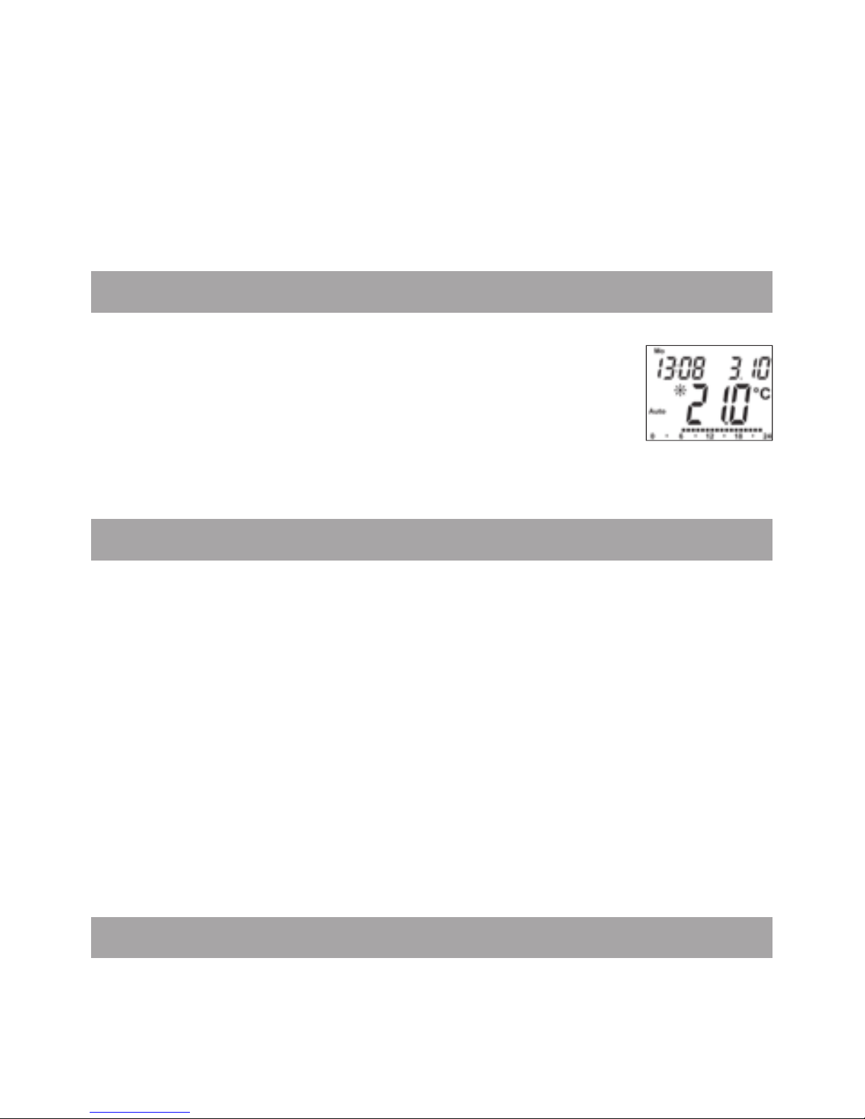
Im Normalbetrieb werden Wochentag, Uhrzeit, Datum, Betriebsmodus, Soll-Temperatur
und Schaltzeiträume angezeigt.
Die Balken für Schaltzeiträume des Wochenprogramms werden für jedes zweite Zeitintervall angezeigt.
(Beispiel unter „11. Wochenprogramm: Beispiele“).
15. Anlernen von Funkkomponenten
Am Stellantrieb können bis zu 4 Systemkomponenten wie
Fernbedienung und Fensterkontakt sowie 1 Wandthermostat angelernt werden.
Drücken Sie die OK-Taste länger als 3 Sekunden.•
Es wird die verbleibende Anlernzeit angezeigt (30 Sek.)•
Jetzt muss das anzulernende Gerät ein Funksignal sen-•
den (z.B. Tastendruck einer Fernbedienung).
Danach wechselt das Display zur Normalansicht.•
Der Stellantrieb reagiert danach auf Funkbefehle angelernter Geräte. Beim Empfang von Fensterkontakt oder
Fernbedienung leuchtet das Display kurz auf.
16. Ablernen von Funkkomponenten
Am Stellantrieb angelernte Komponenten können mit der
Funktion Unlearn „UnL“ wieder abgelernt werden. Dabei
werden alle Funkkomponenten gleichzeitig abgelernt.
Page 13

13
Die Menü-Taste länger als 3 Sekunden drücken•
Mit dem Stellrad den Menüpunkt „UnL“ auswählen•
Mit OK-Taste bestätigen•
Es erscheint „ACC“ im Display, mit OK bestätigen•
17. Betrieb mit Wandthermostat
Soll der Stellantrieb zusammen mit einem Wandthermostat betrieben werden, muss dieser angelernt werden (siehe Abschnitt 15). Nach erfolgreichem Anlernen erscheint
„ECF“ im Display, am Stellantrieb kann keine Einstellung
mehr vorgenommen werden und er reagiert nicht mehr auf
angelernte Fernbedienungen oder Fensterkontakte.
Wird für 60 Min. kein Funksignal vom Wandthermostat
empfangen, verlässt der Stellantrieb den ECF-Modus.
Bis zum nächsten Empfang regelt er autark gemäß Wochenprogramm weiter.
Soll ein Wandthermostat „abgelernt“ werden, müssen Sie
die Batterien im Stellantrieb neu einlegen (ca. 1 Minute
warten). Nach Eingabe von Datum und Uhrzeit kann, vor
Auslösen der Adaptierfahrt, über die Menü-Taste das Ablernen, wie in Abschnitt 16 erklärt, durchgeführt werden.
18. Urlaubsfunktion einstellen
Wenn während eines Urlaubs oder einer Par ty für einen be stimmten Zeitraum eine feste Temperatur gehalten werden
soll, kann die Urlaubsfunktion genutzt werden.
Die Menü-Taste ist so oft kurz zu drücken, bis im Display •
das Koffersymbol (
) erscheint.
Über das Stellrad ist die Uhrzeit einzustellen, bis zu der •
die Temperatur gehalten werden soll.
Bestätigung durch die OK-Taste•
Mit dem Stellrad ist danach das Datum einzustellen•
Bestätigung durch die OK-Taste•
Page 14
14
Mit dem Stellrad die Temperatur einstellen, mit OK be-•
stätigen. Die Anzeige blinkt zur Bestätigung.
Die eingestellte Temperatur bleibt bis zum vorgegebenen
Zeitpunkt bestehen. Danach geht der Stellantrieb in den
Auto-Modus. Funkbefehle von Fensterkontakt und Fernbedienung werden weiterhin ausgeführt.
19. Komfort- und Absenktemperatur
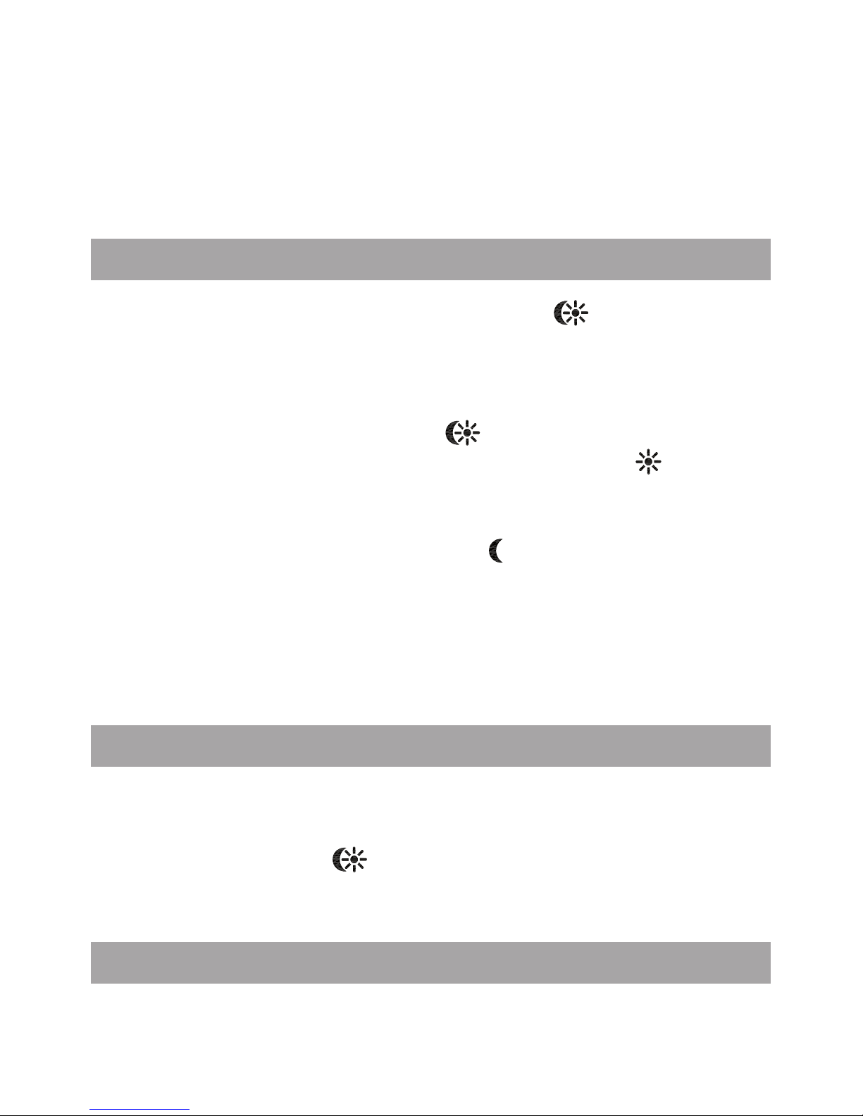
Die Taste Komfort-/Absenktemperatur (
) dient zur komfortablen und einfachen Umschaltung zwischen diesen
beiden Temperaturen. Werkseitig liegen diese bei 21.0°C
und 17.0°C. Sie können wie folgt angepasst werden.
Die Komfort-/Absenktaste ( •
) lange gedrückt halten.
Im Display erscheinen das Sonnensymbol ( •
) und die
aktuelle Komforttemperatur.
Temperatur mit Stellrad verändern, mit OK bestätigen.•
Es erscheinen Mondsymbol ( •
) und Absenktemperatur.
Temperatur mit Stellrad verändern, mit OK bestätigen.•
Auch im Auto-Modus kann die Temperatur über die Taste jederzeit geändert werden. Diese bleibt dann bis zum
nächsten Schaltzeitpunkt des Programms erhalten.
20. Kindersicherung / Bediensperre
Die Bedienung kann gesperrt werden.
Um die Bediensperre zu aktivieren/deaktivieren, sind die •
Tasten Menu und
gleichzeitig kurz zu drücken.
Nach Aktivierung erscheint „LOC“ im Display.•
Zur Deaktivierung beide Tasten erneut drücken.•
21. Heizpause einstellen
Ist die Heizung im Sommer abgeschaltet, können die Batterien geschont werden. Dazu wird das Ventil ganz ge-
Page 15

15
öffnet. Der Verkalkungsschutz wird weiter durchgeführt.
Funkbefehle von Fensterkontakt oder Fernbedienung werden nicht mehr ausgeführt.
Um die Heizpause zu aktivieren, ist das Stellrad im ma-•
nuellen Betrieb (Manu) so lange nach rechts zu drehen,
bis im Display „On“ erscheint.
Zum Beenden ist der manuelle Betrieb (• Manu) zu verlas-
sen oder das Stellrad nach links zu drehen.
22. Frostschutzbetrieb einstellen
Wenn der Raum nicht geheizt werden soll, kann das Ventil
geschlossen werden. Nur bei Frostgefahr wird das Ventil
geöffnet. Der Verkalkungsschutz wird weiter durchgeführt.
Funkbefehle von Fensterkontakt oder Fernbedienung werden nicht mehr ausgeführt.
Um den Frostschutzbetrieb zu aktivieren, ist das Stell-•
rad im manuellen Betrieb (Manu) so lange nach links zu
drehen, bis im Display „OFF“ erscheint.
Zum Beenden ist der manuelle Betrieb (• Manu) zu verlas-
sen oder das Stellrad nach rechts zu drehen.
23. Fenster-auf-Funktion
Der Stellantrieb regelt beim Lüften die Temperatur, um
Heizkosten zu sparen. Währenddessen wird im Display
das Fenster-auf-Symbol (
) angezeigt.
Ohne Fensterkontakt: Der Stellantrieb erkennt eine stark
absinkende Temperatur durchs Lüften automatisch. Fenster-auf-Temperatur und -Zeit sind einstellbar.
Mit angelerntem Fensterkontakt: Die Temperatur wird
nur während der Fensteröffnung heruntergeregelt. Die
Fenster-auf-Temperatur ist einstellbar.
Die Menü-Taste länger als 3 Sekunden drücken•
Mit dem Stellrad den Menüpunkt „AEr“ auswählen•
Mit OK-Taste bestätigen•
Page 16

16
Temperatur/Zeit lassen sich mit dem Stellrad einstellen. •
Abschließend mit OK-Taste bestätigen.
Ohne angelernten Fensterkontakt lässt sich diese Funk-•
tion durch Zeitauswahl „0“ deaktivieren.
24. Offset-Temperatur einstellen
Da die Temperatur am Heizkörper gemessen wird, kann es
woanders im Raum kälter oder wärmer sein. Um dies anzugleichen, kann ein Temperatur-Offset von ±3.5°C einge stellt werden. Werden z.B. 18°C anstatt eingestellter 20°C
gemessen, ist ein Offset von -2.0°C einzustellen.
Die Menü-Taste länger als 3 Sekunden drücken•
Mit dem Stellrad den Menüpunkt „tOF“ auswählen•
Mit OK-Taste bestätigen•
Die Temperatur mittels des Stellrads verändern.•
Bestätigung erfolgt durch die OK-Taste•
25. Werkseinstellungen wieder herstellen
Der Auslieferungszustand des Stellantriebs kann manuell
wieder hergestellt werden. Dabei gehen alle manuell vorgenommenen Einstellungen verloren.
Die Menü-Taste länger als 3 Sekunden drücken•
Mit dem Stellrad den Menüpunkt „rES“ auswählen•
Mit OK-Taste bestätigen•
Es erscheint „ACC“ im Display, mit OK bestätigen•
Page 17
17
26. Fehlerbehebung und Wartung
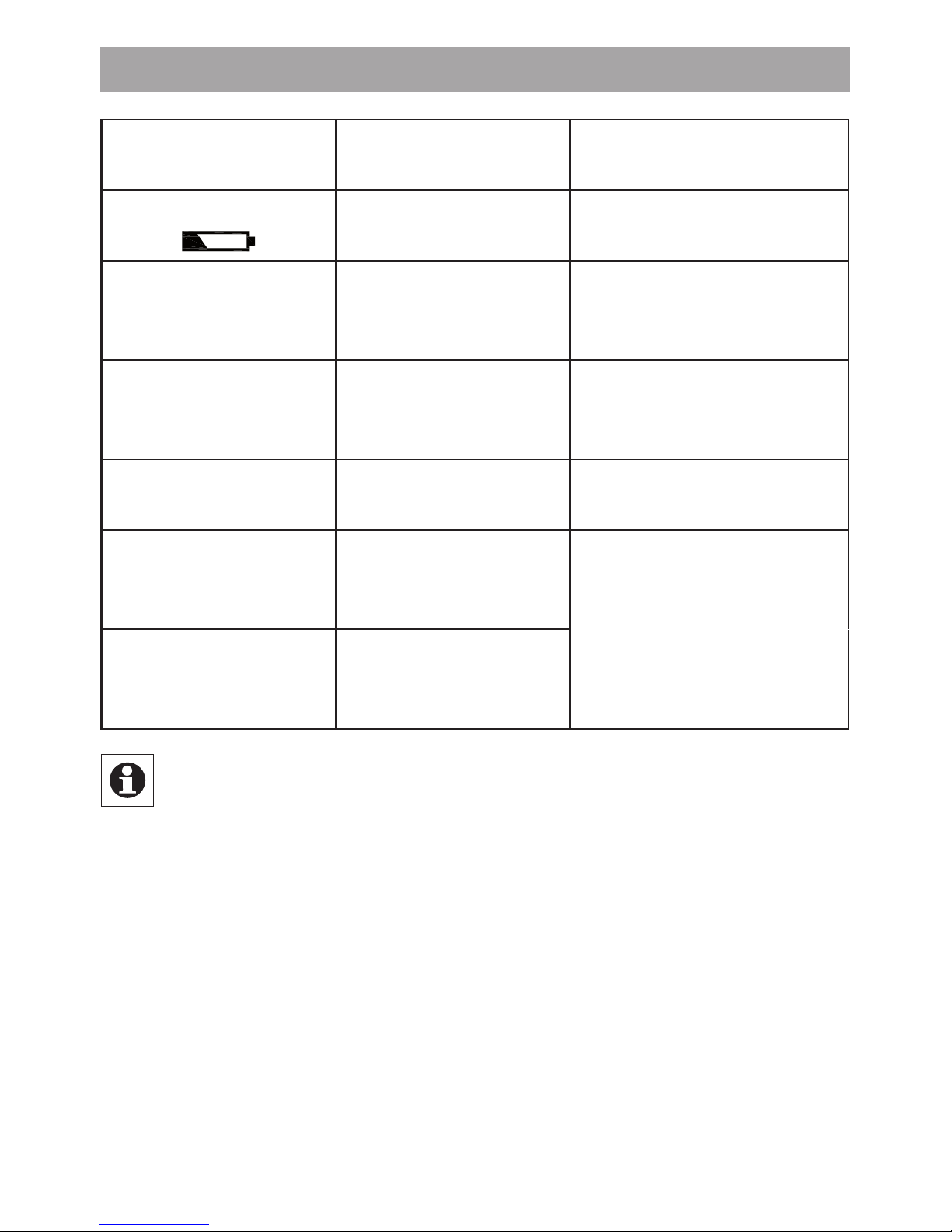
Fehlercode im
Display
Problem Behebung
Batteriesymbol
(
)
Batterieleistung
zu gering
Batterien
austauschen
F1
Ventilantrieb
schwergängig
Installation prüfen,
Heizungsventil
überprüfen
F2
Stellbereich
zu groß
Befestigung
des Stellantriebs
überprüfen
F3
Stellbereich
zu klein
Heizungsventil
überprüfen
F4
Bereits 1 Wand-
thermostat an-
gelernt
Geräte ablernen
F5
Bereits 4 Funk-
komponenten
angelernt
Einmal wöchentlich am Samstag, um 12:00 führt der
Stellantrieb zum Schutz vor Ventilverkalkung eine
Entkalkungsfahrt durch. Dabei erscheint „CAL“ im
Display.
Page 18
18
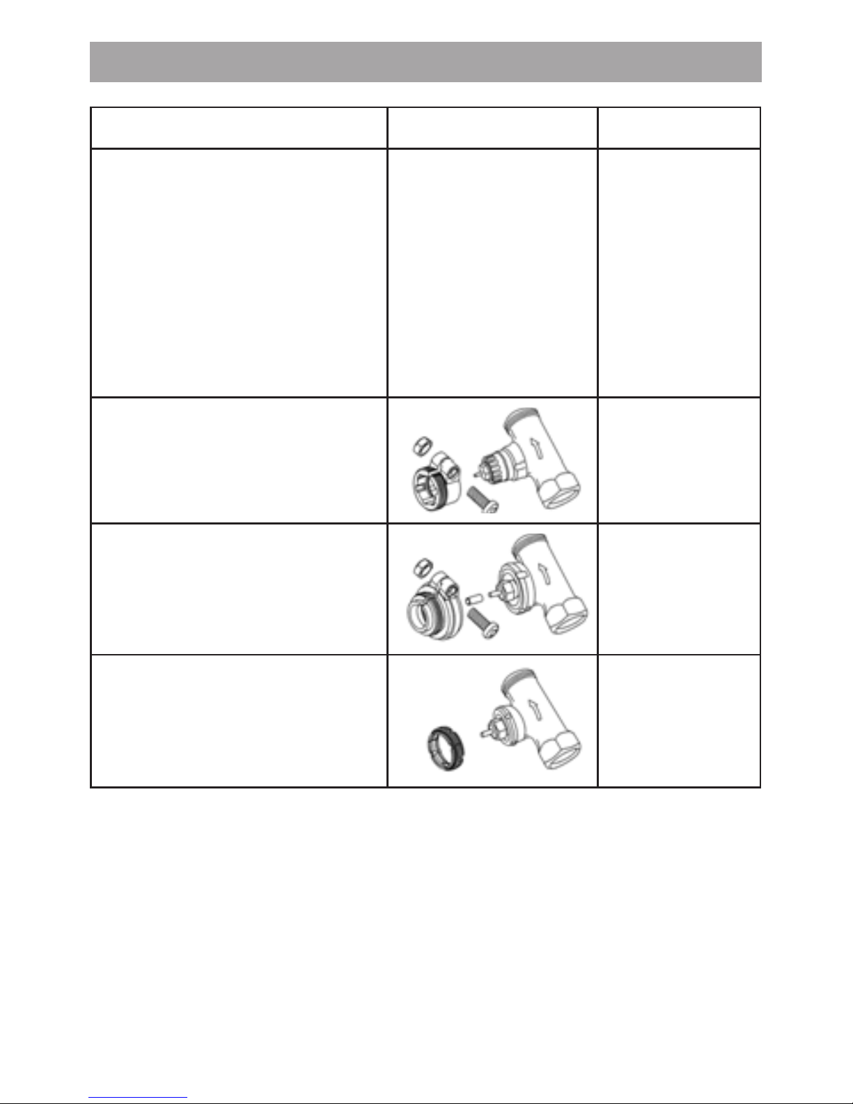
27. Adapterübersicht
Hersteller Abbildung Adapter
Heimeier, MNG,
Junkers,
Landis&Gyr „Duodyr“,
Honeywell-Braukmann,
Oventrop, Schlösser,
Simplex, Valf Sanayii,
Mertik Maxitrol, Watts,
Wingenroth (Wiroflex),
R.B.M., Tiemme, Jaga
kein
Adapter
erforderlich
Danfoss RA
liegt bei
Danfoss RAV
liegt bei
Danfoss RAVL
liegt bei
Weitere Adapter sind als Zubehör erhältlich.
Page 19

19
28. Hinweise zum Funkbetrieb
Die Funk-Übertragung wird auf einem nicht exklusiven
Übertragungsweg realisiert, weshalb Störungen nicht
ausgeschlossen werden können.
Störeinflüsse können u. a. durch Schaltvorgänge, Elek tromotoren oder auch defekte Elektrogeräte hervorgerufen
werden. Die Reichweite in Gebäuden kann stark von der
im Freifeld abweichen. Außer der Sendeleistung und den
Empfangseigenschaften der Empfänger spielen Umwelteinflüsse wie Luftfeuchtigkeit neben baulichen Gegebenheiten eine wichtige Rolle.
Hiermit erklärt die ELV Elektronik AG, dass sich dieses
Gerät in Übereinstimmung mit den grundlegenden Anforderungen und den anderen relevanten Vorschriften der
Richtlinie 1999/5/EG befindet. Die vollständige Konformitätserklärung finden Sie unter www.elv.de.
29. Technische Eigenschaften
Versorgungsspannung: 3 V
Max. Stromaufnahme: 100 mA
Batterien: 2x LR14-Batterie (Baby/C)
Batterielebensdauer: ca. 5 Jahre
Display: LC-Display
Empfängerfrequenz: 868,3 MHz
Gehäuseabmessung: 63 x 70 x 99 mm (B x H x T)
Anschluss: M30 x 1,5
Umgebungstemperatur: +5 bis +55°C
Max. Oberflächentemperatur: +90°C (am Heizkörper)
Linearer Hub: 4,2 mm
Federkraft: max. 80 N
Technische Änderungen, die zur Verbesserung
dienen, sind vorbehalten.
Page 20

20
Table of contents
1. Operation and display................................................21
2. Intended use ..............................................................22
3. Safety instructions .....................................................22
4. Instructions for disposal ............................................22
5. General function ........................................................23
6. (Step 1) Inserting (replacing) the batteries .................23
7. (Step 2) Setting the date and time of day ..................24
8. (Step 3) Installing the energy-saving controller..........25
9. (Step 4)
Mounting the anti-theft/tamper
protection device....... ................................................27
10. Setting the weekly program .......................................28
11. Weekly program: Examples .......................................28
12. Operating modes .......................................................30
13. Configuration menu ...................................................30
14. Display content during normal operation ..................31
15. Teaching in wireless components ..............................31
16. Teaching out wireless components ...........................32
17. Operation with a wall thermostat ...............................32
18. Setting the holiday function .......................................33
19. Comfort and set-back temperatures .........................33
20. Child-proof lock/Operating inhibit .............................34
21. Setting the heating break ...........................................34
22. Setting frost protection mode ....................................34
23. „Window open“ function ............................................35
24. Setting the offset temperature ...................................35
25. Restoring the factory settings ....................................36
26. Troubleshooting and maintenance ............................37
27. Adapter overview .......................................................38
28. Information about radio operation .............................39
29. Technical properties ...................................................39
Please read this manual carefully in order to help you put the device
into operation. Keep the manual handy so you can refer to it at a
later date!
Issue 1 English 08/2010
Documentation © 2010 ELV Elektronik AG. All rights reserved.
98265, V1.0, www.elv.com
Page 21
21
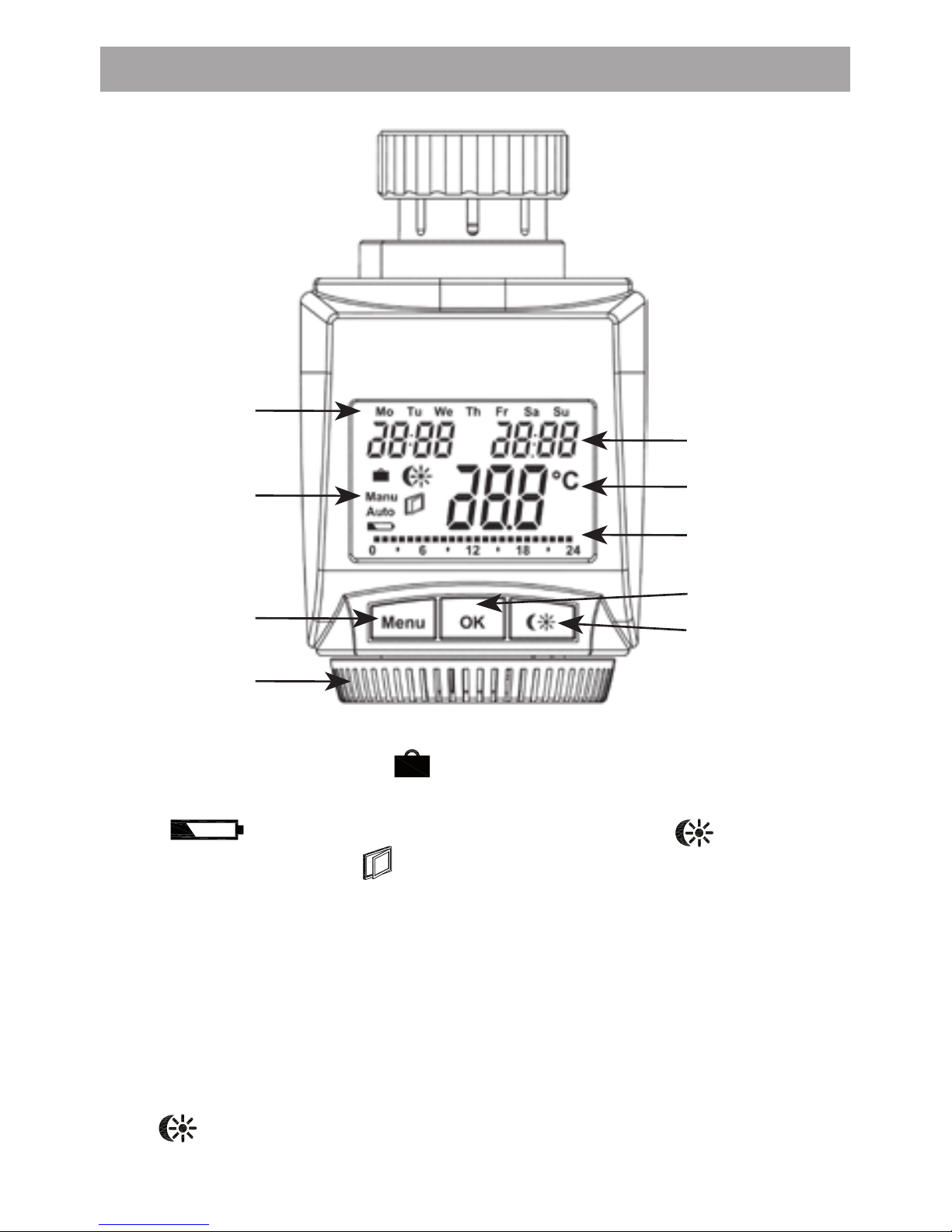
1. Operation and display
A Day of the week
B Holiday function (
), manual operation (Manu), au-
tomatic operation (Auto), “battery empty” symbol
(
), set-back/comfort temperature ( ), “window
open” symbol (
)
C Menu button: Press and hold down the button for more
than 3 seconds to open the configuration menu
D Setting wheel: For making adjustments (e.g. temperature)
E Time and date indicator, menu items, functions
F Current temperature setting
G Switching periods set within weekly program
H OK button: For confirming/saving, teaching in
I
button: For switching between set-back and com-
fort temperatures
A
B
C
D
E
F
G
H
I
Page 22

22
2. Intended use
The energy-saving controller has been designed for the
purpose of controlling a standard heating appliance valve. The device may only be operated indoors and must
be protected from the effects of damp and dust, as well
as solar radiation and sources of radiant heat.
Using the device for a purpose or in a manner other than
that described in this operating manual constitutes a
breach of the “intended use” and shall invalidate the warranty and any liability claims. The same shall apply in the
event of any conversion or modification work. The devices
are intended exclusively for domestic use.
3. Safety instructions
The devices concerned are not intended for children and
must not be used as toys. Do not leave packaging material lying around, as children might be tempted to play with
it, which is extremely dangerous. Do not open the device:
it does not contain any components that need to be serviced by the user. In the event of an error, please return
the device to our service department.
4. Instructions for disposal
Do not dispose of the device with regular
domestic waste.
Electronic equipment must be disposed of at local
collection points for waste electronic equipment in
compliance with local directives governing waste
electrical and electronic equipment.
The CE sign is a free trade sign addressed exclusively to the authorities and does not warrant any
properties.
Page 23
23
5. General function
This energy-saving controller for radiators can be used to
control room temperature on the basis of time. The actuator moves a valve, thereby allowing the amount of
heat flowing to the heating appliance to be controlled.
The controller is compatible with all standard heating
appliance valves. The large illuminated display ensures
user-friendly operation. A wireless receiver allows the
device to receive commands from taught-in system components. The use of BABY cells means that the unit is
practically maintenance-free. The anti-tamper and theft
protection device prevents unauthorised dismantling.
Installation can be achieved in 4 easy steps.
6. (Step 1) Inserting (replacing) the batteries
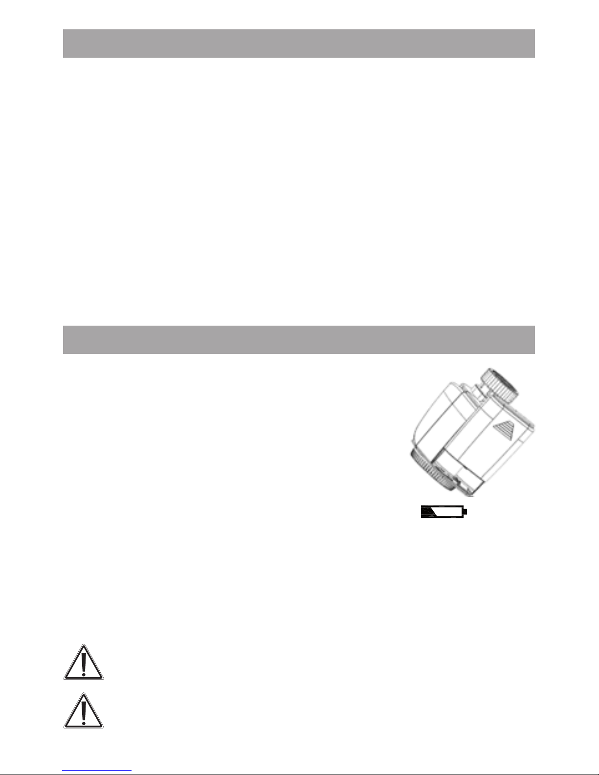
Remove the ba• ttery compartment cover.
Insert 2 new LR14 batteries (Baby/C) into •
the battery compartment, ensuring they
are the right way round.
Reattach the battery compartment cover •
and click into place.
New alkaline batteries have a life of approximately five years. A battery symbol (
) will indicate when the batteries need to be replaced. Before
changing the batteries, you must remove the anti-theft/
tamper protection device. After removing the old batteries, please wait approximately 1 minute before inserting
the new ones. This device does not support operation with
rechargeable batteries.
Never recharge standard batteries.
Doing so will present a risk of explosion.
Do not throw the batteries into a fire.
Do not short-circuit batteries.
Page 24
24
Used batteries should not be disposed of
with regular domestic waste. Instead, they
should be taken to your local battery dis-
posal point.
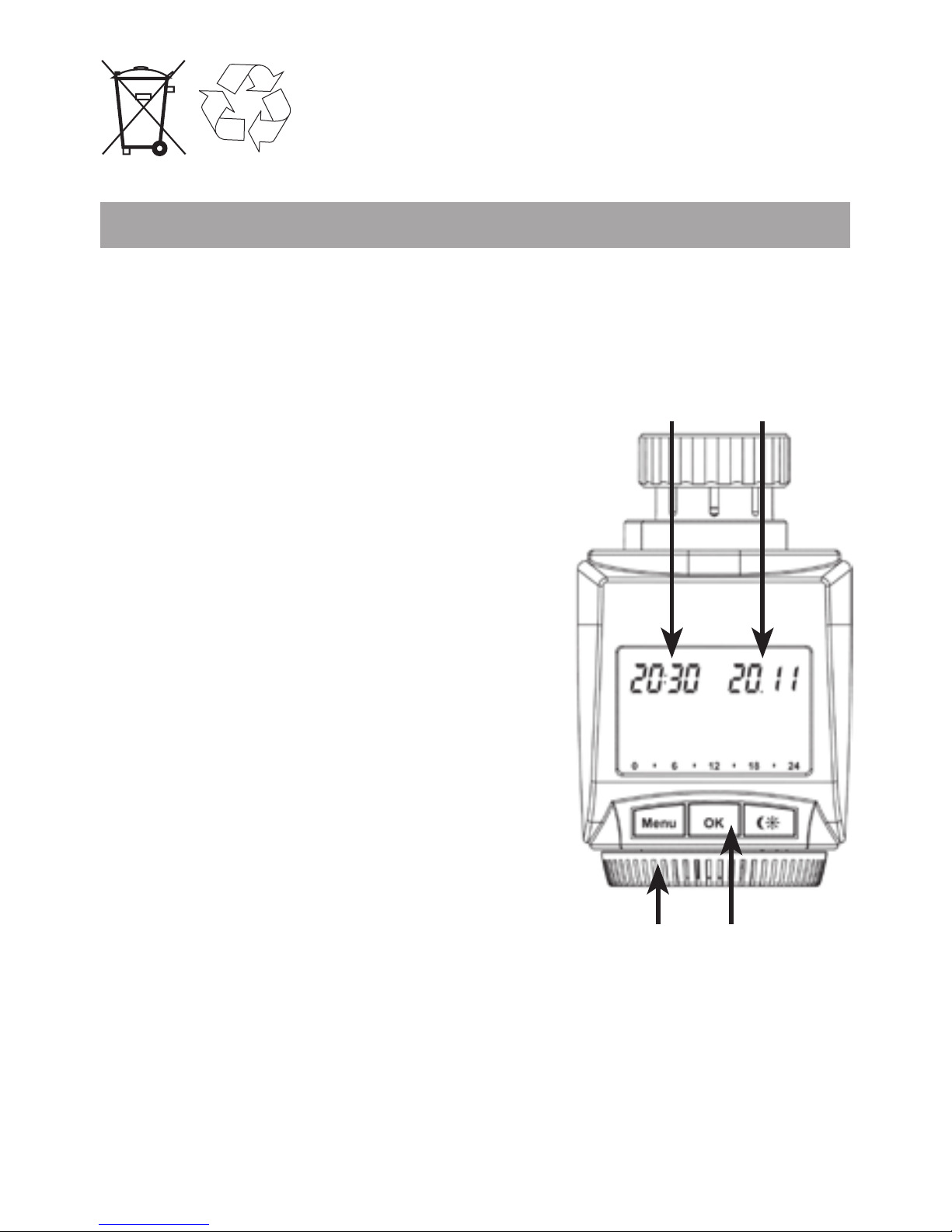
7. (Step 2) Setting the date and time of day
The firmware version number will be displayed briefly once
you have inser ted/replaced the batteries and then you will be
automatically prompted to set the date and time of day.
Use the setting wheel (C) •
to set the year (B).
Confirm with OK (D).•
Use the setting wheel (C) •
to set the month (B).
Confirm with OK (D).•
Use the setting wheel (C) •
to set the day (B).
Confirm with OK (D).•
Use the setting wheel (C) •
to set the hour (A).
Confirm with OK (D).•
Use the setting wheel (C) •
to set the minute (A).
Confirm with OK (D).•
The motor will start moving back the control pin while the
entries are still being made.
If “InS” is displayed with a rotating “•
∏
” symbol, this
indicates that the motor is still moving back. Once the
device is ready for the actuator to be installed on the
valve, just “InS” will appear on the display.
A
C
B
D
Page 25
25
The weekly program and other settings can be cus-•
tomised prior to installation. To do this, press the menu
button when “InS” is shown on the display. For further
details, please see “13. Configuration menu”.
Once programming is complete, “InS” will reappear on •
the display and installation (Step 3) can commence.
When “InS” is visible on the display, you can activate
the teach-in function prior to installation by pressing
the
button briefly.
8. (Step 3) Installing the energy-saving controller
The actuator can be installed on all standard heating
valves. There is no need to drain away water or fiddle
around with the heating system before doing this. First,
you need to remove the old thermostat dial:
Turn the thermostat dial anti-•
clockwise as far as it will go (A).
Release the thermal ring of the •
thermostat (B).
Remove the thermostat from •
the valve (C).
The support ring supplied helps
to fasten the energy-saving controller in a more stable position if
the relevant valve connections are only small.
• Attach the support ring to the
valve connection (D). If the valve
connection is too large to attach
the support ring to it, the stability
is already sufficient and the support ring is not required.
Page 26
26
An adapter will need to be used
in the case of certain valves.
Adapters for Danfoss valves
(RA, RAV, RAVL) are included
in the scope of delivery. For details, please refer to the adapter
overview (see 27).
The adapter must be fully •
latched onto the valve. You
may find it necessary to use
a screwdriver to bend the RA
and RAV adapters far enough
apart.
In the case of the RAV adapter, the extension supplied •
must be attached to the valve tappet.
The RA and RAV adapters must, in addition, be secured •
by means of the bolt and nut supplied.
The energy-saving controller can only be installed if “InS” is
showing on the display. Following installation, the actuator
will perform an adjustment run so that it can adapt to the
valve. During this process, “AdA” will be displayed.
Place the actuator on the valve.•
Tighten the union nut.•
“InS” will appear on the display, press the OK button.•
The actuator will perform an adjustment run (“AdA” will •
appear on the display, operation not possible).
After that, the actuator will be ready for operation (Auto mode).•
If the adjustment run was initiated prior to installation, or if an error message will be displayed (F1, F2,
F3); press OK to move the motor back to the “InS”
position.
Page 27
27
9. (Step 4) Mounting the anti-theft/
tamper protection device
The anti-theft/tamper protection device prevents the radio
energy-saving controller and
its batteries from simply being
removed and stolen.
• Push the anti-tamper protection device into the guide from
below until it engages (E). The
battery compartment can now
not be opened.
• Attach the upper shell (F) and lower
shell (G) to the union nut until they engage. The bars (H) on the shells must slot
into the flange spaces.
• Insert the M3 hexagon socket-head screws (I) and fasten them on the other side with nuts.
The upper shell and lower shell can be mounted in
any position.
The purpose of the lower shell, which is slightly longer,
is to prevent the radio energy-saving controller from
any attempts to remove it by unauthorised persons by
twisting it off. It is long enough to make contact with
the valve when the connection is rotated.
The lower shell should be attached in such a way
that it can as respond as quickly as possible to any
attempts to twist off the controller.
Page 28
28
10. Setting the weekly program
The weekly program allows you to set up to 3 separate
heating periods (7 switching times) for each day of the
week. Programming is performed in relation to the selected days, for which temperatures must be stored for a
period from 00:00 to 23:59.
Press and hold down the menu •
button for more than 3 seconds.
“Pro” will appear on the display.•
Confirm with OK.•
“dAy” will appear on the display. •
The setting wheel can be used
to select an individual day of the
week, all working days, the weekend or the entire week
(example shows working days selected).
Confirm with OK.•
Use the setting wheel to set the first time segment (ex-•
ample shows 0:00 to 6:00).
Confirm with OK.•
Then, select the required temperature for the selected •
time segment (example shows 17.0°C).
Confirm with OK.•
Keep repeating this process until you have finished stor-•
ing temperatures for the period from 0:00 to 23:59.
In Auto mode, the temperature can be modified at any time
via the setting wheel. The modified temperature will then
be retained until the next program changeover.
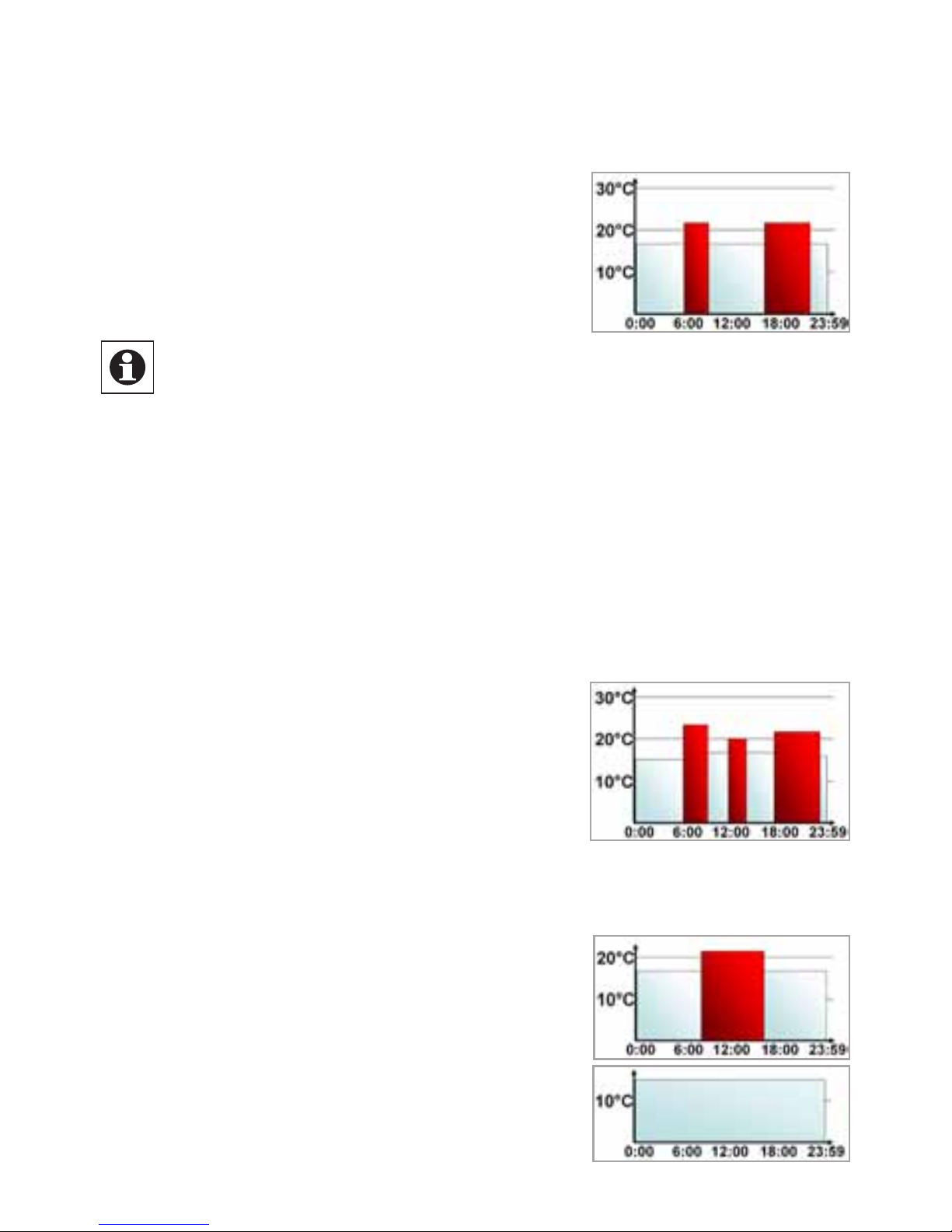
11. Weekly program: Examples
The energy-saving controller allows you to store up to 3
heating periods (7 switching times) with individual temperature settings for each day of the week. The factory set-
Page 29
29
ting consists of two heating phases (from 6:00 until 9:00
and from 17:00 until 23:00 respectively) for every single
day of the week:
From 00:00 to 06:00 17.0°C
From 06:00 to 09:00 21.0°C
From 09:00 to 17:00 17.0°C
From 17:00 to 23:00 21.0°C
From 23:00 to 23:59 17.0°C
To represent the switching periods, the display shows
bars for every other switching interval. In this example, no bars are shown for the interval from 0:00 to
6:00. Bars are only shown on the display for the in-
tervals from 6:00 to 9:00 and from 17:00 to 23:00.
If a room also needs to be heated at around noon, the corresponding program might look like this:
Monday to Sunday
From 00:00 to 06:00 16.0°C
From 06:00 to 09:00 22.0°C
From 09:00 to 12:00 17.0°C
From 12:00 to 14:00 20.0°C
From 14:00 to 17:30 17.0°C
From 17:30 to 23:30 21.0°C
From 23:30 to 23:59 16.0°C
If you have a home office and only want it to be heated
during the day on working days, you can program the following times:
Monday to Friday
From 00:00 to 08:30 17.0°C
From 08:30 to 17:00 21.0°C
From 17:00 to 23:59 17.0°C
Saturday and Sunday
From 00:00 to 23:59 15.0°C
Page 30

30
12. Operating modes
To switch between the 3 operating modes described below, press the menu button briefly (these operating modes
can only be selected following installation/Step 3):
Holiday function• (
): Set a temperature that is to be
maintained until a fixed point in time.
Manu: • Manual operation – The temperature is set manu-
ally using the setting wheel.
Auto: • Weekly program – The temperature is control-
led automatically in accordance with the stored weekly
program.
13. Configuration menu
The configuration menu can be used to modify settings.
To access this menu, press and hold down the menu
button (for more than 3 seconds).
Pro: For setting the weekly program (see Section “10 •
Setting the weekly program”)
dAt: For modifying the time of day and date•
POS: For querying the actuator’s current position•
dSt: Automatic switchover at the start or end of daylight •
saving time can be deactivated.
AEr: For setting the “window open” temperature and time •
so that the temperature is automatically reduced in the
event of ventilation
tOF: For setting the offset temperature•
rES: For restoring the factory settings•
UnL: For teaching out all taught-in wireless components •
Use the setting wheel to select menu items and the OK button to confirm your choice. Press the menu button again to
return to the previous level. After 65 seconds without anything happening, the menu will close automatically.
Page 31

31
14. Display content during normal operation
During normal operation, the following are displayed: day of the week, time of day, date, operating mode, temperature setting and switching periods.
The bars indicating the weekly program’s switching periods are shown for every other time interval. For an example, please refer to “11. Weekly program: Examples”.
15. Teaching in wireless components
The actuator supports the teaching in of up to 4 system
components (e.g. remote control and window contact plus
1 wall thermostat).
Press and hold down the OK button for more than 3 •
seconds.
The remaining teach-in time will be displayed (30 seconds).•
The device being taught-in now needs to send a wireless •
signal (e.g. press button on remote control).
The display will then switch to the normal view.•
Once this has been done, the actuator will respond to wireless commands from taught-in devices. Whenever the actuator receives a signal from a window contact or remote
control, the display will light up briefly.
Page 32

32
16. Teaching out wireless components
Components that have been taught in on the actuator
can be taught out again using the “UnL” (Unlearn) function. All wireless components are taught out at once with
this function.
Press and hold down the menu button for more than •
3 seconds.
Use the setting wheel to select the “UnL” menu item.•
Confirm with OK.•
“ACC” will appear on the display; press OK to confirm.•
17. Operation with a wall thermostat
If the actuator is going to be operated in conjunction with
a wall thermostat, this thermostat will need to be taught in
(see section 15). Once it has been taught in, “ECF” will appear on the display. No further settings can then be made
on the actuator and it will no longer respond to taught-in
remote controls or window contacts.
If no wireless signal is received from the wall thermostat
for a period of 60 minutes, the actuator will exit ECF
mode.
It will then assume control of the temperature, which it will
continue to regulate in accordance with the weekly program until the next wireless signal is received.
To teach out a wall thermostat, you must reinsert the batteries in the actuator (wait for approx. 1 minute). Once you
have entered the date and time of day, you can use the
menu button (before the adjustment run is initiated) to perform the teach-out process as described in section 16.
Page 33
33
18. Setting the holiday function
If you want a fixed temperature to be maintained for a set
period of time while you are on holiday or during a party,
you can make use of the Holiday function.
Press and release the menu button repeatedly until the •
suitcase symbol (
) appears on the display.
Use the setting wheel to set the end of the time period •
during which the temperature is to be maintained.
Press the OK button to confirm.•
Then use the setting wheel to set the date.•
Press the OK button to confirm.•
Use the setting wheel to set the temperature; press OK to •
confirm. The display will flash to confirm your settings.
The set temperature will remain in force until the specified time. After that, the actuator will adopt Auto mode.
Wireless commands from the window contact and remote
control will continue to be executed.
19. Comfort and set-back temperatures
The comfort/set-back temperature button (
) provides
an easy and convenient way of switching between these
two temperatures. The factory settings are 21.0°C and
17.0°C respectively. To adapt them, proceed as follows:
Press and hold down the comfort/set-back temperature but- •
ton (
) for more than 3 seconds.
The sun symbol ( •
) will appear on the display along
with the current comfort temperature.
Use the setting wheel to modify the temperature; •
press OK to confirm.
The moon symbol ( •
) will appear together with the setback temperature.
Use the setting wheel to modify the temperature; •
press OK to confirm.
Page 34

34
The temperature can even be modified in Auto mode at any
time by using this button. The new setting will be retained
until the program’s next switching time.
20. Child-proof lock/Operating inhibit
Operation can be inhibited.
To activate/deactivate the operating inhibit, briefly press •
the Menu and
buttons at the same time.
Once the function is active, “LOC” will appear on the •
display.
To deactivate the function, press both buttons again.•
21. Setting the heating break
If the heating is being switched off for the summer, you
can save battery power. This involves opening the valve
up fully. Limescale protection measures remain in place.
Wireless commands from the window contact or remote
control will no longer be executed.
To activate the heating break, turn the setting wheel •
clockwise during manual operation (Manu) until “On”
appears on the display.
To terminate the heating break, quit manual operation •
(Manu) or turn the setting wheel anticlockwise.
22. Setting frost protection mode
If you do not want the room to be heated, the valve can
be closed. It will only be opened again if there is a risk of
freezing due to frost. Limescale protection measures remain in place. Wireless commands from the window contact or remote control will no longer be executed.
Page 35

35
To activate frost protection mode, turn the setting wheel •
anticlockwise during manual operation (Manu) until “OFF”
appears on the display.
To terminate frost protection mode, quit manual opera-•
tion (Manu) or turn the setting wheel clockwise.
23. “Window open” function
If the room is being ventilated, the actuator controls the
temperature to save on heating costs. While this function is active, the “window open” symbol (
) appears
on the display.
Without window contact: The actuator will automatically detect a significant drop in temperature due to ventilation. You can set your own “window open” temperature and time.
With taught-in window contact: The temperature will
only be reduced during the time that the window is left
open. You can set your own “window open” temperature.
Press and hold down the menu button for more than •
3 seconds.
Use the setting wheel to select the “AEr” menu item.•
Confirm with OK.•
Use the setting wheel to set the temperature/time. •
Then press OK to confirm.
Without a taught-in window contact, this function can •
be deactivated by selecting a time of “0”.
24. Setting the offset temperature
The temperature is measured at the heating appliance itself, with the result that other parts of the room may be
warmer or colder than this. To allow for this, you can set
a temperature offset of ±3.5°C. If, for example, a temperature of 18°C is measured somewhere within the room
Page 36

36
instead of the 20°C set, it means that an offset of -2.0°C
needs to be configured.
Press and hold down the menu button for more than •
3 seconds.
Use the setting wheel to select the “tOF” menu item.•
Confirm with OK.•
Use the setting wheel to modify the temperature.•
Press the OK button to confirm.•
25. Restoring the factory settings
You can reset the actuator to its initial state manually. This
will clear all the settings that have been made manually.
Press and hold down the menu button for more than •
3 seconds.
Use the setting wheel to select the “rES” menu item.•
Confirm with OK.•
“ACC” will appear on the display; press OK to confirm.•
Page 37
37
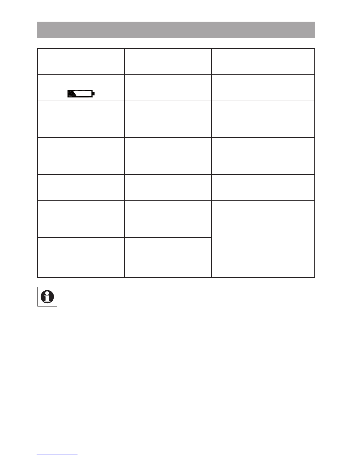
26. Troubleshooting and maintenance
Error code on
display
Problem Remedy
Battery symbol
(
)
Battery power
too low
Replace batteries
F1
Valve actuator
sluggish
Check installation,
inspect heating
valve
F2
Adjusting range
too large
Check
actuator
fastening
F3
Adjusting range
too small
Check heating
valve
F4
1 wall thermo-
stat already
taught in
Teach out devices
F5
4 wireless com-
ponents already
taught in
At 12:00 every Saturday, the actuator performs a
weekly descaling function to prevent valve calcification. “CAL” will appear on the display.
Page 38
38
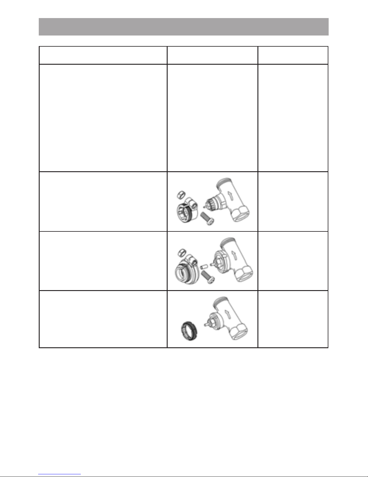
27. Adapter overview
Manufacturer Figure Adapter
Heimeier, MNG,
Junkers,
Landis&Gyr „Duodyr“,
Honeywell-Braukmann,
Oventrop, Schlösser,
Simplex, Valf Sanayii,
Mertik Maxitrol, Watts,
Wingenroth (Wiroflex),
R.B.M., Tiemme, Jaga
No adapter
required
Danfoss RA
Included
in scope of
supply
Danfoss RAV
Included
in scope of
supply
Danfoss RAVL
Included
in scope of
supply
Other adapters available as accessories.
Page 39

39
28. Information about radio operation
Radio transmission is performed on a non-exclusive transmission path, which means that there is a possibility of
interference occurring.
Switching operations, electric motors or faulty electric de vices are some of the reasons why interference may occur. The range of transmission within buildings can deviate
greatly from open air distances. Besides the transmitting
power and the reception characteristics of the receiver,
environmental influences such as humidity and local structures also play an important role.
ELV Elektronik AG hereby declares that this device conforms with the essential requirements and other relevant
regulations of Directive 1999/5/EC. The full declaration of
conformity is provided at www.elv.de.
29. Technical properties
Supply voltage: 3 V
Max. current consumption:
100 mA
Batteries: 2x LR14 batteries (Baby/C)
Battery life: Approx. 5 years
Display: LC display
Receiver frequency: 868.3 MHz
Housing dimensions: 63 x 70 x 99 mm (W x H x D)
Connection: M30 x 1.5
Ambient temperature: +5 to +55°C
Max. surface temperature: +90°C (of radiator)
Linear travel: 4.2 mm
Spring force: max. 80 N
We reserve the right to make any technical changes
that constitute an improvement to the device.
Page 40

40
Bedienungsanleitung
ELV Elektronik AG · PF 1000 · D-26787 Leer
 Loading...