

Elura Black label Series, Black label B6.5Z.2 Instructions Manual
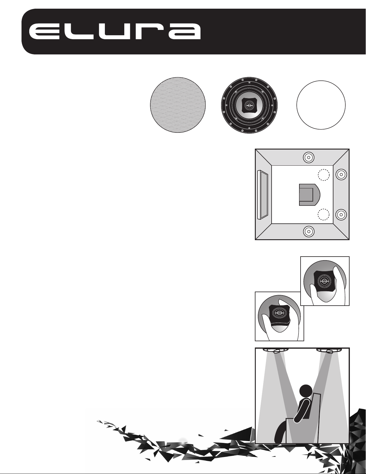
model B6.5Z.2
black label series
2-way In-Ceiling Speaker System
Speaker with magnetic baffle and
self-contained mounting clamps
FIG. 1
Congratulations on choosing an Elura InCeiling Loudspeaker. Like all Elura products,
great care has been taken in their design.
Their combination of advanced engineering
and state-of-the-art materials will provide
you with years of listening pleasure, while
blending smoothly into your home’s decor.
Before you get started, it is a good idea to
identify all the parts and hardware (See FIG. 1).
Magnetic grille with white
inner scrim cloth
Where To Place Your In-Ceiling Speakers
Placement can make all the difference in how your speakers sound, and how easy
they will be to install. Carefully consider where your speakers should be positioned.
optimum performance, speakers should be mounted to the left and right of the
For
main listening area and a minimum of 8 to 10 feet apart (See Fig. 2). Avoid mounting
speakers in stud cavities containing electrical wiring, heating ducts, water pipes, etc.
Make sure the ceiling materials are sturdy enough to support the weight of the
speakers.
Adjustable Tweeters (FIG. 3)
The tweeter in your Elura speaker may be adjusted, allowing you to tailor the speaker
to better fit the listening area. The overall smoothest response is achieved with the
tweeter facing straight out; however, you may find the sound more pleasing by
aiming tweeters toward a particular listening area. To adjust the tweeter, grasp the
outside of the tweeter plate and gently pivot it toward the listening area.
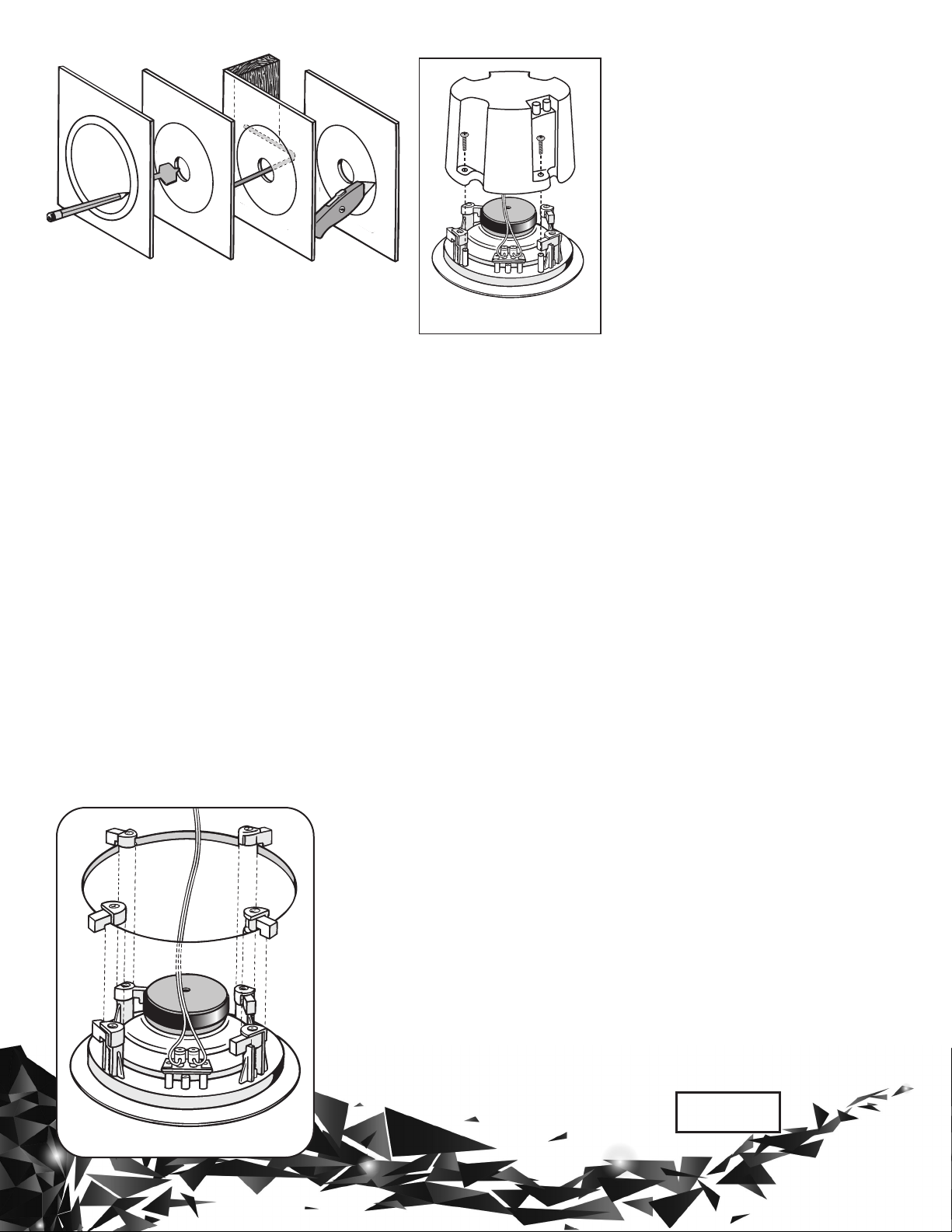
Speaker Installation In Existing Construction (See Fig. 4 on
back) Once you have selected the location for your speakers, you are ready to install
them. You will need the following:
• Stud Finder • Drill & Drill Bits • Wire Cutter/Strippers • Speaker Wire
• Pencil • Phillips Screwdriver • Utility Knife or Drywall Saw • Masking Tape
NOTE: (See Fig. 5 on back) If you plan to use the optional back can enclosure,
you need to attach it now (refer to back can manual for installation instructions).
Elura recommends the use of 16-gauge wire minimum. For wire options consult your
retailer or custom audio contractor.
1. Elura Speakers are designed to be installed in the ceiling or wall area between
studs. Using a stud finder, make sure you are between two studs. Tape the supplied
template to the wall and lightly trace around it with a pencil.
2. Cut the hole using your drywall saw. You may want to start with a small hole in the
center of the outline. This will allow you to check for any obstructions that may exist behind the desired location. CAUTION: Be certain electrical wiring, water pipes or heating
ducts do not interfere in the planned installation areas prior to drilling or cutting the wall.
3. Run speaker wire from your amplifier or speaker switching device to speaker location.
4. Carefully remove the grille and set it aside where it won’t get bent. If you like the
standard white finish of your speakers, skip to step 5, but if you want your speakers
to blend in with a colored wall or
ceiling, now is the time to paint
your speaker’s perforated grille.
Remove the inner grille scrim
cloth before painting.
Cutout template
1
FIG. 2
Elura ceiling speakers can be used as rear
surround channels
by mounting them
(1) on each side of,
(2) just behind, or
(3) in back of the
viewing position.
1
FIG. 3
Pivoting
tweeter
3
2
2
3
Continued on reverse
Warranty
All Elura products come with a limited
lifetime liability warranty. This warranty
includes parts and labor repairs on all
components found to be defective in
material or workmanship under normal
conditions of use. This warranty shall
not apply to products which have been
abused, modified or disassembled.
FIG. 4
Continued from front
(Grille painting hint: Use a paint roller
that is nearly out of paint to first paint
the inside of the grille, then the outside. This will avoid paint filling the
grille perforations.)
5. Attach the wire to the input terminals on the rear of the speaker.
Remember to maintain proper
polarity with the amplifier by
attaching the positive (+) lead to the
red terminal and the negative (-) lead
to the black terminal.
6. See Fig. 6. With the speaker wire
attached to the speaker, slide the
speaker up inside the cutout hole.
Center the speaker in the cutout hole
and turn the four locking screws
clockwise until the speaker is drawn
up snugly to the wall board from behind, clamping the speaker in place.
Try to tighten each screw equally.
Replace the speaker grille by gently
placing it over the speaker until the
magnets “grab” hold of the grille.
FIG. 5
Optional back can
New Construction
1. Determine speaker locations and
mark them on your plans for future
reference.
2. If possible, run speaker wires after
HVAC and electrical wiring is in place.
3. Secure speaker wires in place
along the run with insulated staples
only and be careful not to pierce the
wire’s insulation. Allow a bit of slack for
expansion of building materials.
4. Needless to say, the actual
speakers should not be installed until
the wall board is in place. In the
meantime, leave several feet of wire
coiled up and secured at the back
side of the mounting hole.
5. To complete the installation follow
steps 2 through 5 above.
Operational Check
After making all connections, it’s a
good idea t
working properly. Turn on your surround or stereo system making sure
the volume control is turned down
and that the balance control is in the
center position. Activate a musical or
movie source such as FM, a CD or
DVD player. Gently turn up the volume, you should hear sound coming
from your new speakers. If no sound
is heard from any or all speakers,
switch off the system immediately
and check for open or loose connections, wrong polarity or shorts, or
improper source selection.
o make sure everything is
A speaker that fails under conditions
other than those covered will be re-
paired at the current price of parts and
labor in effect at the time of repair. Such
repairs are warranted for 90 days from
the day of reshipment to the BUYER. If
the unit is delivered by mail, customers
agree to insure the unit or assume the
risk of loss or damage in transit.
Under no circumstances will a unit be
accepted without a return authorization
number. The warranty is in lieu of all
other warranties expressed or implied,
including without limitations, any other
implied warranty or fitness or merchantability for any particular purpose,
all of which are expressly disclaimed.
Proof of sale may be required in order to
claim warranty.
Specifications
• Max. Power Handling: 5 - 70 Watts
• Sensitivity: 91dB @ 1 watt/1 meter
• Freq. Response: 55 Hz-20,000 Hz
• Driver Complement: 61/2˝ (165mm)
compression molded mineral filled
polymer cone woofer with rubber
surround
1
liquid-cooled PEI dome tweeter
• Nominal Impedance: 8 ohms
• Overall Dimensions: 9.25˝ (diameter)
round x 4.23˝ D (235mm x 107mm)
• Required Ceiling Cutout: 8.25˝
(diameter) round (210mm)
mm) zero-diffraction, pivoting,
/2˝ (13
www.elura.audio
FIG. 6
MSTR
 Loading...