

Page 1

User’s Guide for MBUser’s Guide for MB--350U(350U(--485M)485M)
Ver. 1.2
ELT SENSOR
Page 2

Ø INDEX
I. Hardware
1 Packing List
II. ELT_WSD emulation Program
2 Installation
3 Front Panel Display
1 Connection with PC
2 Monitoring
3 CO2 Level Setting Change
4 Warning Level (CO₂)
5
Specifications
6 Calibration
7
Cautions
III. RS-485 Protocol (Sending only)-Option
1 H/W Interface
2 Data Packet
1
Page 3
Hardware
I.
1 Packing List
2 Installation
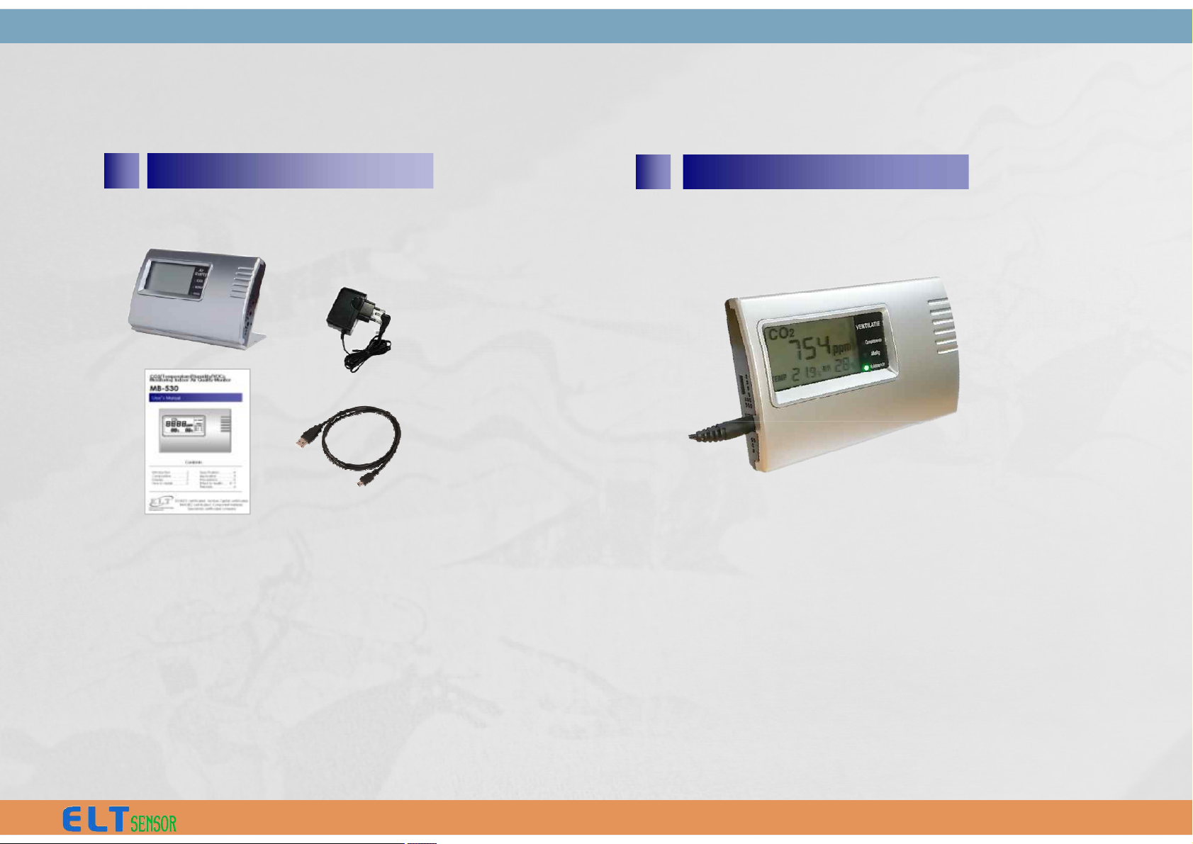
1. Main Body/Holder
2. 2. AC/DC 12V Adaptor
3. Manual
4. USB Cable
• Connect power jack to main body.
(Requiring 2 minutes stabilizing time)
• USB cable is available for connection to Computer
and ELT_WSD program enables alarm range setting
and measured data save on Computer.
2
Page 4
Description
Product Air Quality Monitor (CO2,Temp,Humidity)
CO2 range
/ Resolution / Accuracy
NDIR sensor 0 ~ 9,999 ppm /
/ 1ppm / 30ppm ± 3%
Warming up 6 Sec.(for output), 5 Min.(for accuracy)
Temperature
/ Accuracy
± 0.3 ℃ typical (-40℃ ~ 80℃)
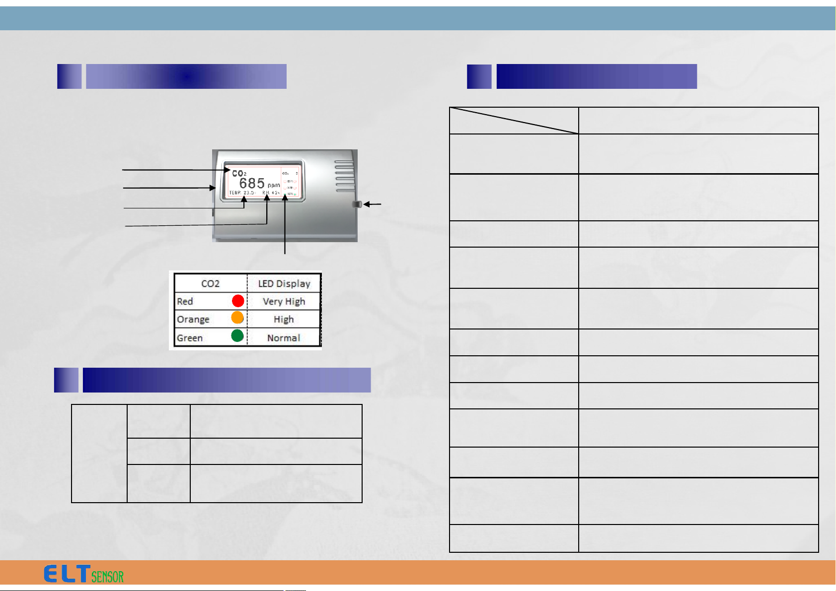
§ MB-350U(-485M) Model
CO2 (ppm)
Mini USB port
TEMP. (℃)
R.H. (%)
CO2 Level LED Display
Alarm On/Off
Switch
5
Specifications
3 Front Panel Display
Humidity
/ Accuracy
± 2% RH typical (0~ 99% RH)
Power Supply DC 12V/1A AC/DC Adaptor
Current Consumption Normal : 90mA, Peak : 416mA
Alarm CO2 Level LED display / Melody
Operating Condition 0 ~ 50℃ / 0 ~ 95%
Storage Temp. -30℃ ~ 70℃
Dimension
(main body)
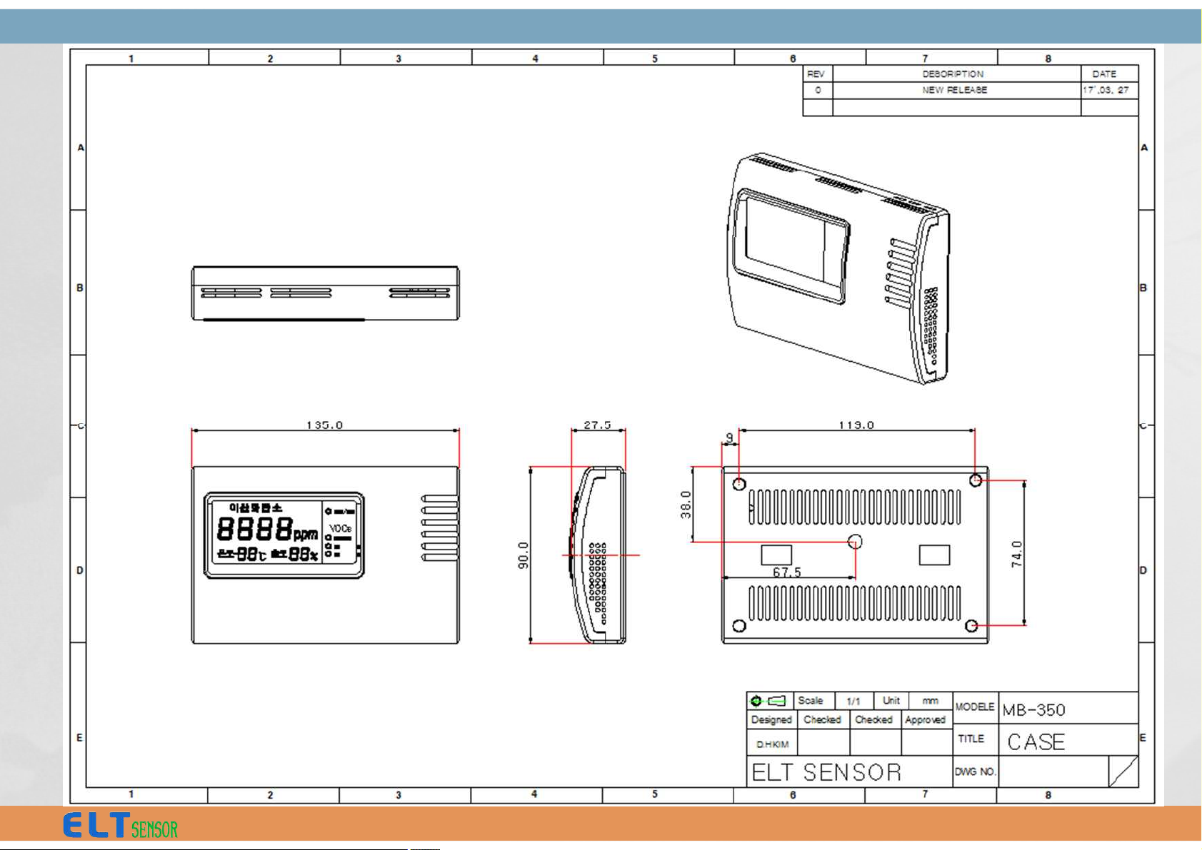
135.0 x 90.0 x 28.0 mm (W*H*D)
Certificate CE, ROHS
CO2
LED
Very
High
≥ 1,400 ppm
High 1,000 ~ 1,400 ppm
Normal < 1,000 ppm
4
Warning Level (CO₂)
3
Page 5
4
Page 6
7 Cautions
Please keep followings to prevent damage
and malfunction of product.
1) Use provided adaptor. When using other
adaptors, make sure to use proper rating
and standard product. It may causes
damage and measurement error.
6 Calibration
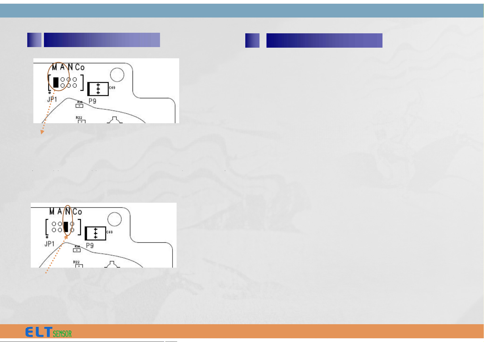
‘M’ : Manual re-calibration during 10 minutes
in fresh air (or 400ppm CO2gas) - MCDL
‘A’ : Automatic calibration mode – ACDL
2) Do not disassemble, modify or repair the
products.
3) Avoid shock, vibration, direct sun light.
None: Factory calibration operation mode
(for Green house and other Agricultural
usage)
‘A’ : Automatic calibration mode – ACDL
(Monthly auto calibration , For HVAC, ventilation usage)
‘Co’ : Not available (don’t care)
5
Page 7
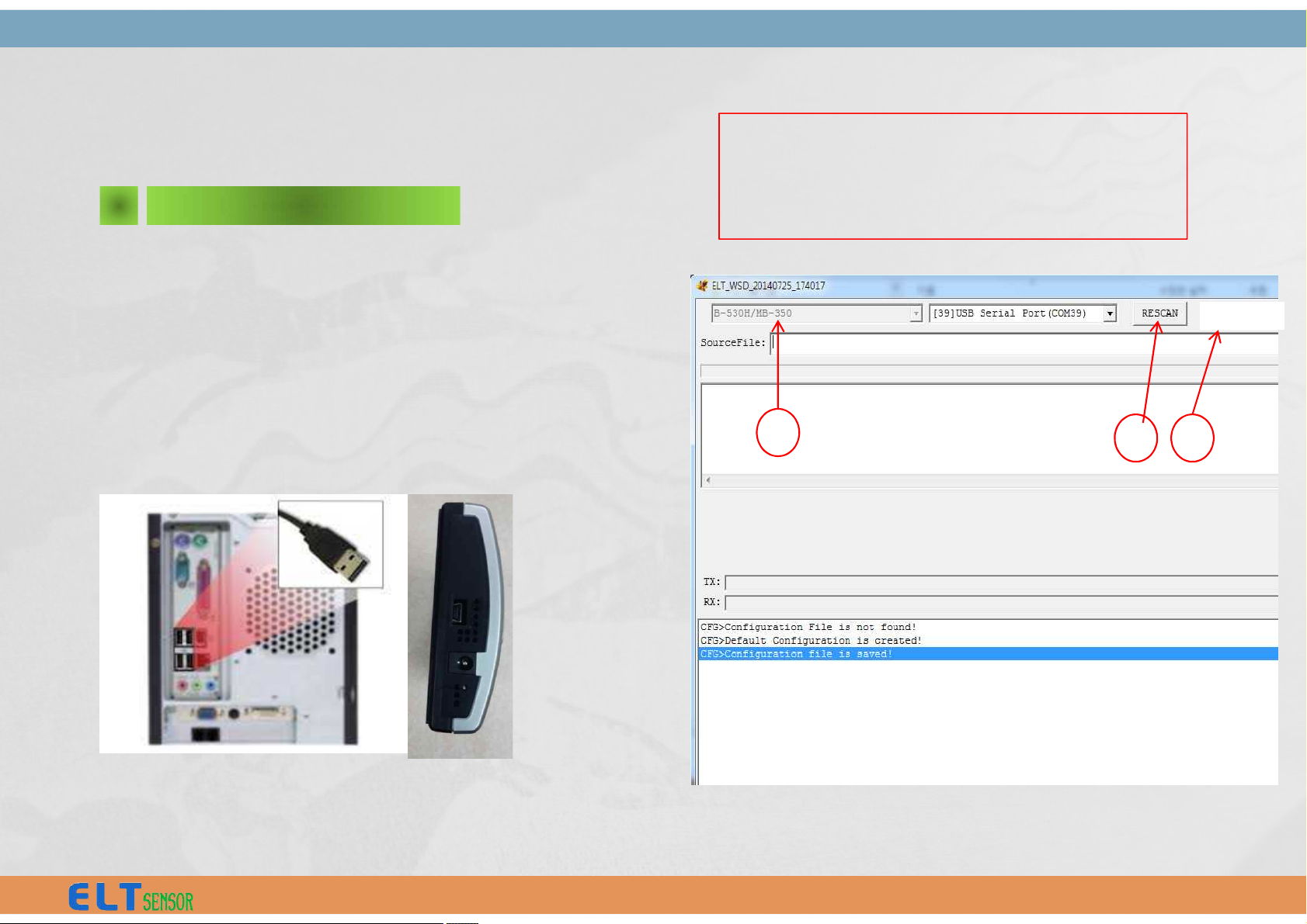
ELT-WSD program is developed for customer to change the CO2
Alarm range of MB-350 with
USB 2.0 interface of PC.
Execute "ELT_WSD_MB-350.exe" with mini-USB cable connected
between PC and MB-350, of which 12V Power (12V AC/DC Adapter)
should be provided.
ELT_WSD emulation Program
II.
1 Connection with PC
① Select model “B-530H/MB-350”
② Press "RESCAN" button and
(auto) select USB Serial Port (COM xx)
③ Select 19,200 bps
1
2 3
19200bps
6
Page 8
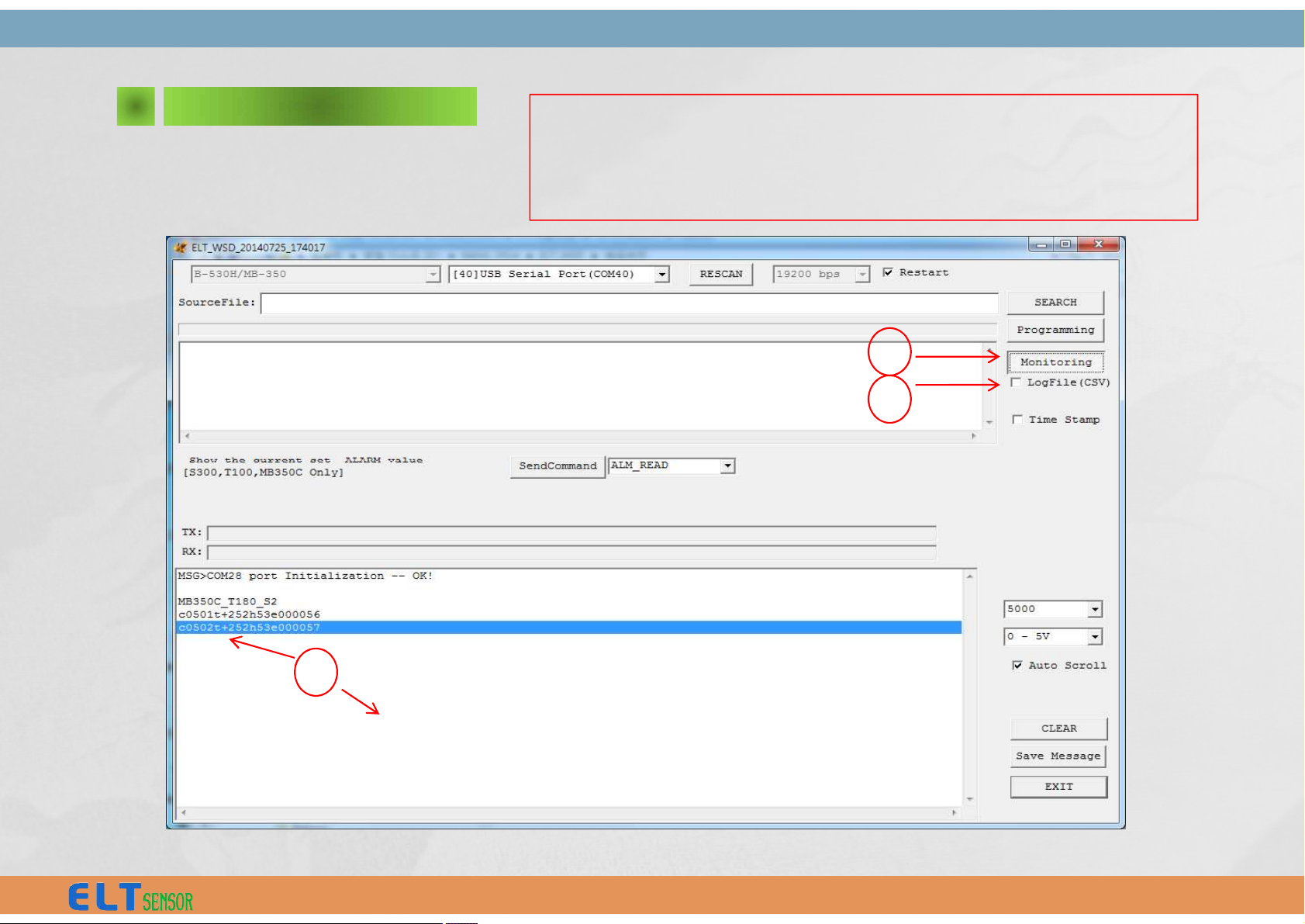
2 Monitoring
4
④ Press “Monitoring”
⑤ Check “ v “ LogFile(CSV) for save (the monitor data
file saved to sub directory of ELTWSD_EK100 program)
⑥ View and analysis the Monitoring data
5
v
c0502t+252h53e000057 ⇒ c 0502 t+252 h53 e000057
® CO2 , 502ppm , temp +25.2°C , humidity 53% , e: option (not available)
6
7
Page 9
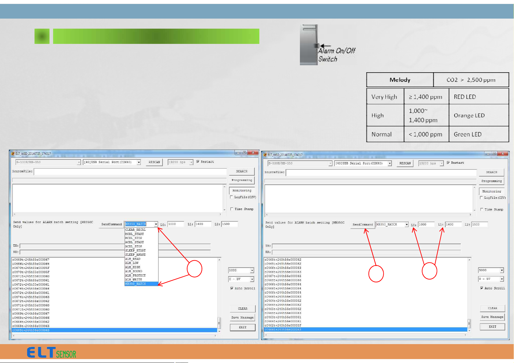
As the ‘Monitoring’ Button is pressed.
① Select "MB350_BATCH" of ‘Send Command’ menu
② Type in ‘ppm’ value for CO2 Level , the default values are L0 : 1000 ppm, L1 : 1400ppm, L2 : 2500ppm
(Low ) : (High ) : (Very High )
[GREEN] < L0 < [ORANGE] < L1 < [RED]
③ Click Box "Send Command“ so that changed Alarm Level L0 & L1 & L2 to be fixed.
CF) L2 (Sound Alarm range) is deactivated.
3 CO2 Level Display Settings
l Melody Warning
- MUTE : Press the switch for 0.5 sec.
- Off/On : Press the switch for 3 sec.
1
2
3
8
Page 10
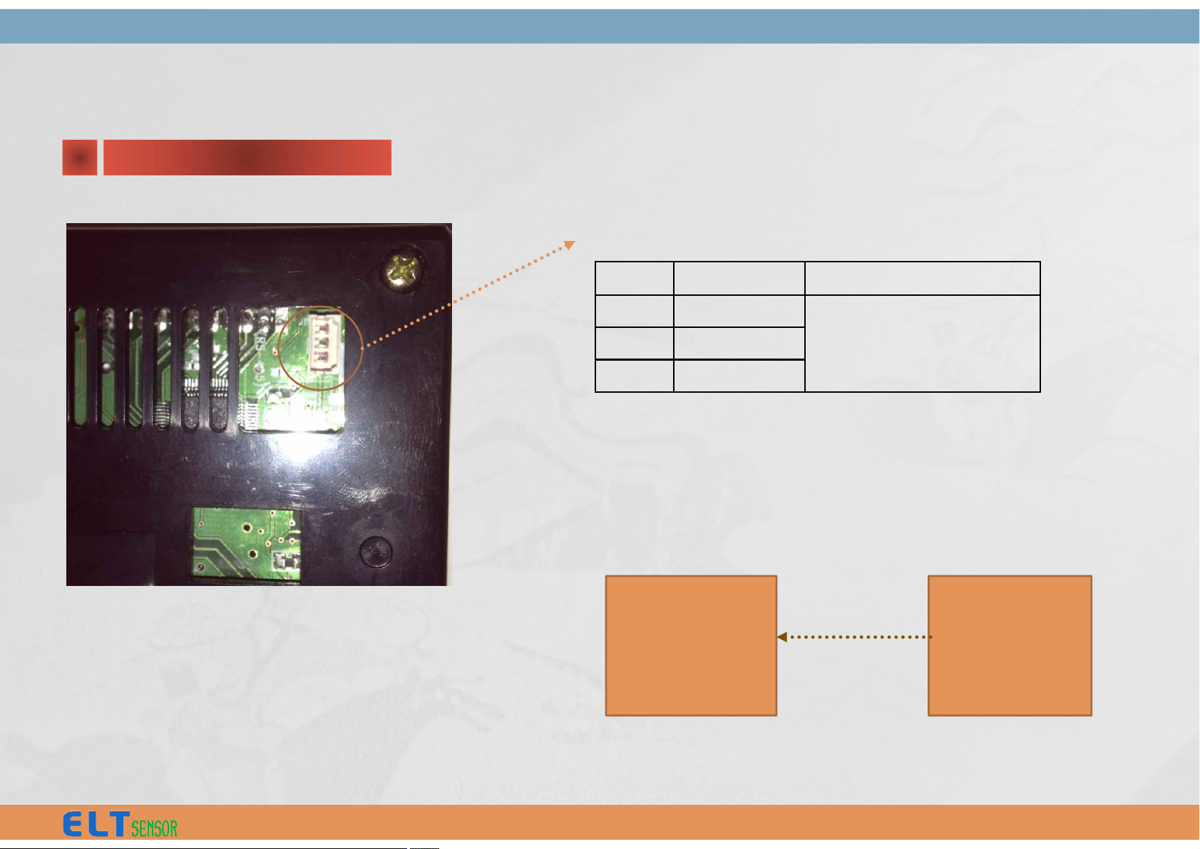
1 H/W Interface
Pin No
Pin Name
Note
1
485A
3 Wire / Master mode only.
2
485B
3
GND
A. Pin Connection: 3 pin Connector (CN1)
RS-485 Protocol (Sending only with Fixed ID)
II.
Slave
MB-350-485
:
:
MB-350-U-485
Master
* Reply delay : 10mS
B. Data Handshaking Sequence
Slave sends data to host upon request via RS485 line.
9
Page 11

STX
ID
CONF
CO2
TEMP
HUMD
VOC
CSUM
ETX
0xFA
0xF0
0xFF
(fixed)
-
MSB
LSB
MSB
LSB
-
Field
Byte
Name
Value
STX
B0/B1
Start Code
0xFA 0xF0
IDB2ID
0xFF (fixed)
CONF
B3
Device Configuration
If bit is set, corresponding sensor is installed.
Bit 0 : VOCs sensor
Bit 1 : Humidity sensor
Bit 2 : Temperature sensor
2 Data Packet
If bit is set, corresponding sensor is installed.
Bit 0 : VOCs sensor
Bit 1 : Humidity sensor
Bit 2 : Temperature sensor
Bit 3 : CO2 sensor
Bit 4 ~ Bit 7 : 0x00
CO2
B4/B5
CO2 Concentration, PP
M
2 byte integer value
If reading is 450 then actual CO2 concentration is 450ppm
TEMP
B6/B7
Temperature, ℃
2 byte integer value
Temp = value/10
If reading is -103 then actual temperature is -10.3 ℃.
HUMD
B8
Humidity, %
1 byte integer value
Temp = value
If reading is 75 then actual, humidity is 75%.
VOCs
B9
VOCs
0x00 : Normal, 0x10 : High, 0x40 : Very High
CSUM
B10
Checksum
Check Sum = Low byte of sum (B0 + B1 … + B9)
ETX
B11
End of code
0x05
10
Page 12

 Loading...