

Page 1
ELTROPLAN-REVCON
Operating instructions
Power feedback unit
REVCON
SVCS
Power range 7 ... 33kW
Rated voltage 400V
V 2.0 As of 03/10
Page 2

Contents
1 Preface and general information .......................................................................................... 3
1.1 About these Operating Instructions ..................................................................................... 3
1.1.1 Terminology used .......................................................................................................... 3
1.1.2 Type determinator ......................................................................................................... 4
1.2 Scope of delivery ................................................................................................................. 4
1.3 Legal regulations.................................................................................................................. 5
1.4 EC-Directives / Declaration of conformity .......................................................................... 6
1.4.1 What is the purpose of EC-Directives? ......................................................................... 6
1.4.2 What is the meaning of the CE-mark? .......................................................................... 6
1.4.3 EC-Low-Voltage Directive ........................................................................................... 6
1.4.4 EC-Directive Machinery ............................................................................................... 8
2 Safety information ............................................................................................................. 10
2.1 General safety information ................................................................................................ 11
2.2 Safety-responsible persons ................................................................................................ 15
2.3 Usage as directed ............................................................................................................... 15
2.4 Layout of the safety information ....................................................................................... 16
2.5 Residual hazards ................................................................................................................ 16
2.6 General instructions ........................................................................................................... 17
3 Technical data .................................................................................................................... 27
3.1 Characteristics .................................................................................................................... 27
3.2 General data / application conditions................................................................................. 28
3.3 Rated data .......................................................................................................................... 29
3.3.1 Power feedback unit .................................................................................................... 29
3.3.2 Current load ................................................................................................................. 30
3.3.4 Fuses and wire cross sections ...................................................................................... 34
3.3.4.1 Series fuses .............................................................................................................. 34
3.3.4.2 Internal fuses ............................................................................................................ 35
3.3.5 RFI-filter ..................................................................................................................... 36
3.3.6 SKS-module ................................................................................................................ 36
4 Installation ......................................................................................................................... 37
4.1 Mechanical installation ..................................................................................................... 37
4.1.1 Important hints ........................................................................................................... 37
4.2 Dimensions ........................................................................................................................ 38
4.2.1 Power feedback unit .................................................................................................... 38
4.2.2 RFI-filters .................................................................................................................... 41
ELTROPLAN-REVCON page 1
Page 3

Contents
4.3 Electrical installation ......................................................................................................... 43
4.3.1 Operator’s safety ......................................................................................................... 43
4.3.2 Protection of the power feedback unit ........................................................................ 43
4.3.3 Mains types / Mains characteristics ............................................................................ 44
4.3.4 Specifications of the used wires ................................................................................. 44
4.4 Connection ........................................................................................................................ 45
4.4.1 Power connection ....................................................................................................... 45
4.4.1.1 Wiring schematic ..................................................................................................... 47
4.4.2 Fan supply ................................................................................................................... 49
4.4.3 Control wires .............................................................................................................. 49
4.4.4 Control functions ........................................................................................................ 49
4.5 Application example ......................................................................................................... 53
4.6 Installation of a power feedback unit in a CE-typical drive system .................................. 54
4.6.1 Installation .................................................................................................................. 55
4.6.2 Connection of a RFI-filter .......................................................................................... 56
4.6.3 Design of an EMC-conformal cabinet ........................................................................ 57
4.6.4 Remarks ...................................................................................................................... 58
4.6.5 Installation of control wires ........................................................................................ 59
5 Commissioning .................................................................................................................. 60
5.1 First powering up .............................................................................................................. 60
6 Configuration .................................................................................................................... 61
7 Troubleshooting and fault elimination .............................................................................. 64
7.1 LED-messages ................................................................................................................... 65
8 Service ............................................................................................................................... 66
9 Appendix ........................................................................................................................... 67
9.1 Options .............................................................................................................................. 67
9.2 REVCON Product overview ............................................................................................. 69
9.3 Contact .............................................................................................................................. 70
Seite 2 ELTROPLAN-REVCON
Page 4

Preface and general information
1 Preface and general information
1.1 About these Operating Instructions
• These Operating Instructions help you to work properly on and with the
power feedback units REVCON SVCS. They contain safety information
which must be observed and information which are necessary for an undisturbed operation of the units together with the exploitation of all the advantages of the system.
• All persons who work on and with the power feedback units REVCON
SVCS, must have the Operation instructions available and observe all
relevant notes and instruction.
• The Operating Instructions must always be in a complete and perfectly
readable state.
1.1.1 Terminology used
Power feedback unit
For „Power feedback unit REVCON SVCS“ in the following the term
„Power feedback unit“ is used.
Controller
For the frequency inverter which is used together with the power feedback unit
in the following the term „Controller“ is used.
Drive system
For a drive system with power feedback units, controller and other components
of the drive system in the following the term „Drive system“ is used.
ELTROPLAN-REVCON page 3
Page 5

Preface and general information
1.1.2 Type determinator
SVCS 33 - XXX - 1 - 230 V AC
for up to 50% duty cycle
Auxiliary voltage e. g. 230V
Number of fans
Mains voltage e. g. 400 (3 x 400V AC)
max. feedback power e. g.33 (33 kW)
Including SKS-R
SVCS = Power feedback unit
1.2 Scope of delivery
• 1 Power feedback unit REVCON
• 1 Operating Instructions
After receipt of delivery, check immediately whether the scope of supply
matches with the accompanying papers. We do not accept any liability for deficiencies claimed subsequently.
Claim
• visible transport damage immediately to the forwarder .
• visible deficiencies/incompleteness immediately to ELTROPLAN
REVCON.
page 4 ELTROPLAN-REVCON
Page 6
Preface and general information
•
•
1.3 Legal regulations
Labelling Nameplate CE-mark Manufacturer
Power feedback units REVCON SVC are
unequivocally marked by the contents of
Conforms the EC Low
Voltage Directive
the nameplate.
Patent rights
The power feedback unit REVCON
is protected in Germany and Europe by patents :
Patent-No.: DE 3938654C1 and Patent-Nr.: 90123584.6-2207.
Patent infringements become prosecute.
Application
as directed
Power feedback unit REVCON
SVC
• Must only be operated under the conditions prescribed in these instructions.
• Are components
– to feedback electrical energy.
– used for installation into a machine.
– used for assembly together with other components to from a machine.
• Are electric units for the installation into control cabinets or similar enclosed operating hous-
ing.
• Comply with the requirements of he Low-Voltage Directive
• Are not machines for the purpose of the Machinery Directive
• Are not to be used as domestic appliances, but only for industrial purpose.
Drive systems with power feedback unit REVCON
SVC
• Comply with the EMC-Directive if they are installed according to the guidelines of CE-typical
drive systems.
• Can be used
– on public and non-public mains.
– in industrial as well as residential and commercial premises.
• The user is responsible for the compliance of this application with the EC directives .
Liability
The information, data and notes in these Operating Instructions met the state of the art at the
time of printing. Claims referring to power feedback units which have already been supplied
cannot be derived from information, illustrations and descriptions given in these Operation Instructions.
• The specifications, processes and circuitry described in these Operating Instructions are for
guidance only and must be adapted to your own specific application. ELTROPLAN-REVCON
does not take responsibility for the suitability of the process and circuit proposals.
• The indications given in these Operating Instructions describe the features of the product with-
out warranting them.
• ELTROPLAN-REVCON does not accept any liability for damage and operating interference
caused by:
– disregarding these instructions
– unauthorized modifications to the power feedback unit
– operating errors
– improper working on and with the power feedback unit
Warranty
Warranty conditions: see sales and delivery conditions of ELTROPLAN-REVCON GmbH.
• Warranty claims must be made immediately after detecting defects or faults.
• The warranty is void in all cases where liability claims cannot be made.
Disposal Material recycle disposal
Metal
Plastic
l
l
Printed-board assemblies -
ELTROPLAN-
REVCON
Edisonstraße 3
D-59199 Bönen
-
-
l
ELTROPLAN-REVCON page 5
Page 7

Preface and general information
1.4 EC-Directives / Declaration of conformity
1.4.1 What is the purpose of EC-Directives?
The EC-Directives have been drawn up by the European council to define
common technical standards and certification procedures within the European
Community. At the moment there are 21 EC-Directives for product sectors.
The directives are or will be converted in national laws by the member states.
If a certificate is conferred in one member state, it is valid in all other member
states automatically.
The directives only describe the basic standards. The technical details are or
will be described in harmonized European standards.
1.4.2 What is the meaning of the CE-mark?
After an conformity-assessment-procedure the harmony with the standards of
the EC-Directives certified by fixing the CE-mark. Within the EC there are no
trading obstacles for a CE-marked product.
Power feedback units with CE-mark themselves are compliant with the LowVoltage Directive only. . For observing the EMC Directive recommendations
are made.
1.4.3 EC-Low-Voltage Directive
(73/23/EEC)
Modified by: CE – Marking Directive (93/68/EEC)
General:
• The Low-Voltage Directive is valid for all electrical equipment which is
used at a nominal voltage between 50V and 1000V AC and between 75V
and 1500V DC together with customary environment conditions. Excluded
is e.g. the use of electrical equipment in explosive areas and electrical
components of lifts for persons or material.
• Aim of the Low-Voltage Directive is to put only those products into com-
merce which don’t endanger the safety of persons and animals as well as
the preservation of material assets.
page 6 ELTROPLAN-REVCON
Page 8
Preface and general information
EC-declaration of conformity
According to the EC-Low Voltage Directive /73/23/EEC)
Modified by: CE – Marking Directive (93/68/EEC)
The power feedback units REVCON SVC have been developed, designed and
manufactured in accordance with the above mentioned EC-Directive and in
sole responsibility of
ELTROPLAN-REVCON Elektrotechnische Anlagen GmbH,
Edisonstraße 3, D-59199 Bönen
Considered standards:
Standard
DIN VDE 0160 5.88 +A1 / 4.89 +A2 / 10.88
PRDIN EN 50178
Class VDE 0160 / 11.94
DIN VDE 0100 Guidelines for the desing of
EN 50529 IP type of protection
DIN EN 50081 Part 2 3.94 Basic standard noise emission
DIN EN 50082 Part 2 3.85 Basic standard noise emission
Equipement of power installations with
electronic components
power installations
ELTROPLAN-REVCON page 7
Page 9

Preface and general information
1.4.4 EC-Directive Machinery
(89/392/EEC)
Modified by: 1. modification guideline (91/368/EEC)
2. modification guideline (93/44/EEC)
CE – marking guideline (93/68/EEC)
General:
As defined by the machinery guideline a „machine“ is a unit of combined
components or devices, from which at least one has moving parts, and of handling devices, control and energy circuits and so on, which have been combined for a specific application (like treating, moving, processing of a material).
page 8 ELTROPLAN-REVCON
Page 10

Preface and general information
EC-declaration of the manufacturer
In the sense of the EC-Directive Machinery (89/392/EEC)
modified by: 1. Modifying Directive (91/368/EEC)
2. Modifying Directive (93/44/EEC)
CE – Labelling Directive (93/68/EEC)
The power feedback units REVCON SVC have been developed, designed and
manufactured in accordance with the above mentioned EC Directive in exclu-
sive responsibility of
ELTROPLAN-REVCON Elektrotechnische Anlagen GmbH,
Edisonstraße 3, D-59199 Bönen
When installing the machines, commissioning (i.e. the staring of operation as
directed) the power feedback units is prohibited until it is proven that the ma-
chine corresponds to the regulations of the EC Directive 89/392/EEC (Machin-
ery Directive).
ELTROPLAN-REVCON page 9
Page 11

Safety information
2 Safety information
Safety and application notes
for controller
1. General
During operation, power feedback unit may have, according to
their type of protection, live, bare, in some cases also movable or
rotating parts as well as hot surfaces.
Non –authorized removal of required cover, inappropriate use, incorrect installation or operation, creates the risk of severe injury to
persons or damage to material assets.
Further information can be obtained from the documentation.
All operations concerning transport, installation and commissioning as well as maintenance must be carried out by qualified,
skilled personnel (IEC 364 and CENELEC HD 384 or DIN VDE
0100 and IEC-Report 664 or DIN VDE 0110 and national regulations for the preventions of accidents must be observed).
According to this basic safety information qualified skilled personnel are persons who are familiar with the erection, assembly,
commissioning and operation of the product and who have the
qualifications necessary for their occupation .
2. Application as directed
Power feedback units are components which are designed for installation in electrical systems or machinery.
When installing in machines, commissioning of the power feedback unit (i.e. the starting of operation as directed) is prohibited
until it is proven, that the machine corresponds to the regulations
of the EC Directive 83/392/EEC (Machinery Directive); EN
60204 must be observed.
Commissioning (i.e. starting operation as directed) is only allowed
when there is compliance with the EMC-Directive89/336/EEC.
The power feedback units meet the requirements of the LowVoltage Directive 73/23/EEC. The harmonized standards of the
prEN 50178/DIN VDE 0160 series together with EN 604391/DIN VDE 0660 part 500 and EN 60146/DIN VDE 0558 are applicable for the power feedback unit. The technical data and information on the connection conditions must be obtained from the
nameplate and the documentation and must be observed in all
cases.
3. Transport, Storage
Notes on transport, storage and appropriate handling must be observed
The power feedback unit has to protected from inadmissible
stress. In particular during transport and handling no components
are allowed to be bend and / or isolating distances may not be altered. The units are equipped with electrostatic sensitive devices,
which may be damaged by improper handling. Therefore it has to
be avoid to get in contact with electronic components. If electronic components are damaged mechanically the unit must not be
put into operation, as it cannot be ensured, that all relevant standards are observed. Climatic conditions must be observed according to prEN 50178
(to : Low-Voltage Directive 73/23/EEC)
4. Erection
The devices must be erected and cooled according to the regulations of the corresponding documentation.
The power feedback units must be protected from inappropriate
loads. Particularly during transport and handling, components
must not be bent and / or isolating distances must not be changed.
Touching of electronic components and contacts must be avoided.
Power feedback units contain electro-statically sensitive components which can easily be damaged by inappropriate handling.
Electrical components must not be damaged or destroyed mechanically (health risk are possible!).
5. Electrical Connection
When working on live power feedback units, the valid national
regulations for the prevention of accidents (e.g. VBG 4) must be
observed. Before any installation or connection works, the pant
has to be switched off and to be secured properly.
The electrical installation must be carried out according to the appropriate regulations (e.g. cable cross-sections, fuses, PEconnection). More detailed information is included in the documentation. When using the power feedback unit with controllers
without safe separation from the supply line (to VDE 0100) all
control wiring has to be include in further protective measures
(e.g. double insulated or shielded, grounded and insulated) .
Notes concerning the installation in compliance with EMC – such
as screening, grounding, arrangement of filters and laying of cables – are included in the chapter installation of this documentation. These notes must be also observed in all cases for power
feedback units with the CE-mark. The compliance with the required limit values demanded by the EMC legislation is the responsibility of the manufacturer of the system or machine.
6. Operation
Systems where power feedback units are installed, if applicable,
have to be equipped with additional monitoring and protective devices according to the valid safety regulations e.g. law on technical tools, regulations for the prevention of accidents, etc. .
After disconnecting the power feedback unit from the supply voltage, live parts of the power feedback unit and power connections
must not be touched immediately, because of possibly charged
capacitors. For this, observe the corresponding labels on the drive
controllers.
During operation, all covers and doors must be closed.
7. Maintenance and service
The manufacturer’s documentation must be observed.
This safety information must be kept!
The product-specific safety and application notes in
these Operating Instructions must also be observed!
page 10 ELTROPLAN-REVCON
Page 12

Safety information
2.1 General safety information
• These safety regulations are not entitled to completeness. In case of ques-
tions please contact our technicians.
• When commissioning the power feedback units is compliant with the state
of the art. The power feedback unit generally allows safe operation.
• The statements of this manual describe the attributes of the products with-
out guaranteeing them.
• The power feedback unit may expose persons, the power feedback units it-
self and other material to danger, if
– non qualified personal works at and with the power feedback unit.
– The power feedback units is used in opposite to its purpose.
• Power feedback units have to be projected in a way, that they fulfil their
function and don’t expose persons to danger, if they are mounted correctly
and are used in accordance with their purpose. This applies also for the in-
terplay with the whole plant.
• The units, operational data and circuit details described in this manual
have to be understood analogously and have to be checked for transferabil-
ity to each application.
• For the reasons of personal safety, the observance of the EMC-regulations
and for the regular cooling the operation of the device is only allowed
with a closed cover of the housing and with mounted flanges!
•
• Use the drive system only in flawless condition.
•
Modifications of the power feedback units without consultation of a
REVCON-technician are not allowed generally.
ELTROPLAN-REVCON page 11
Page 13

Safety information
•
The warranty given by us expires, if the unit is modified or (even partially)
dismantled or if it is used in contradiction to our instructions.
•
The constructor of the plant, who has to know the technical guidelines,
bears the responsibility for the correct selection and arrangement of the
electrical components.
•
Putting into operation of the power feedback unit is only admissible at
VDE-conform nets of electrical power supply. Non observance may dam-
age the device!
•
In accordance with the corresponding standards and guidelines the opera-
tion on even for a short time over-compensated networks (cosϕ≤1) respec-
tively on un-choked compensation-units is not admissible. If this is done
nevertheless, overvoltages will occur (caused by oscillating currents),
which may damage all connected components, especially electronic units
like controllers and power feedback units.
•
To low powered or unloaded generators and to regulating transformers it is
never allowed to feed back power without a previous consultation of our
application department. Otherwise unintended voltage rises / excess volt-
ages are generated, which may damage or destroy REVCON and com-
bined units!
• Before operating at nets without reference to neutral ground additional
safety measures (e.g. installation of over voltage suppressors like MOV’s)
have to be done. If necessary, please ask for technical support by our tech-
nicians.
• An undisturbed operation of the power feedback unit is only probable, if
the following instructions are observed. If these instructions are not ob-
served, tripping of the unit and damages may occur.
♦ Pay attention to the correct values of mains and DC-bus voltage.
♦ Separate power and control wires (> 15cm)
♦ Use shielded or twisted control wires. Connect both ends of the
shield to ground!
page 12 ELTROPLAN-REVCON
Page 14

Safety information
♦ When using the digital input devices, only use suitable switching de-
vices, whose contacts are able to switch the connected voltages.
♦ Connect the housings of drive, controller and power feedback unit to
ground carefully. Connect shields of power cables to ground at both
ends with as big surface as possible (remove lacquer)!
♦ Connect the cabinet or the plant by a star-shaped network to ground
(ground loops have to be avoided!)
• The power feedback unit has been designed for a fixed connection to
mains only. Especially when using RFI-filter leakage current values>
3,5mA may occur. The cross section of the earthing conductor must be al
least 10mm² copper, or a second conductor has to be connected in parallel
(star shaped grounding network).
• If components are used, which have no electrical separated inputs / outputs
it is necessary to equalize the potentials (e.g. by a equalizing wire). If this
is not observed, these components may be damaged by equalizing currents.
• When carrying out an insulations test in accordance with VDE0100/part
620 the device has to be disconnected to avoid damage to the power semi-
conductors. This procedure corresponds with the standard, as each device
performs a high voltage test in accordance with VDE 0160 (EN 50178) in
the course of final testing after manufacturing.
ELTROPLAN-REVCON page 13
Page 15

Safety information
• A standard fault-current circuit breaker (sensitive on peak currents) is not
allowed to be used as the only protective measure when using controller
and power feedback unit Caused by a DC-component in the mains current
a controller with 3-phase input voltage may prevent a fault-current circuit
breaker from tripping in case of a earth fault. In accordance with VDE
0160 a fault-current circuit breaker is not allowed to be used as the only
protective measure. In dependence on the kind of network (TN, IT, TT)
further protective measures in accordance with VDE 0100 part 410 are
necessary. For a TN-network this may be an over current protection, for a
IT-network a insulation supervision with pulscode-measurment. For all
kind of networks protective insulation (-transformer) may be used, if re-
quired power and length of wires allow that. When selecting a fault current
circuit breaker the following measures have to be considered:
♦ The fault current circuit breaker has to be compliant with the VDE
0664 standard.
♦ The tripping current should be 300mA or more, to prevent a prema-
ture tripping caused by the leakage current of the controller. In de-
pendence on the load, the length of the motor cables and the usage of
a RFI-filter the leakage current may even be much higher.
Faults current circuit breaker, which are sensitive to all kinds of leakage
currents, grant a good protection and are suitable as the only protection
measurement for one ore three phase controllers. The connection instruc-
tions of the manufacturer has to be observed.
page 14 ELTROPLAN-REVCON
Page 16

2.2 Safety-responsible persons
User
• User is any natural or legal entity, who uses the drive system or by whom
order the drive system is used.
• The user respectively his security officer have to grant
– that all relevant regulations, instructions and laws have to be observed
– that only qualified personnel works with or at he drive system
– that the relevant manual is available for the personnel during any works.
– that non-qualified personnel is prohibited to work on the drive system.
Qualified personnel
Qualified personnel are persons who are, based on their education, experience,
instruction and knowledge about standards and guidelines, regulations for the
Safety information
prevention of accidents and the situation in the plant, authorized by the safety
officer of the plant to execute the necessary works and are able to recognize
possible dangers and to avoid them.
(Definition of qualified personnel in accordance with IEC 364)
2.3 Usage as directed
Power feedback units are electrical drive components, which are directed to be
installed in electrical plants or machines. They have to be used only for drive
systems with infinity variable speed controls of 3-phase asynchronous or per-
manent magnet motors. The usage with other electrical loads is not permitted
and may damage the devices. The power feedback unit may only be connected
to symmetrical networks. Non-observance may damage the devices.
ELTROPLAN-REVCON page 15
Page 17
Warning of hazardous
FFFF
STOP
STOP
Safety information
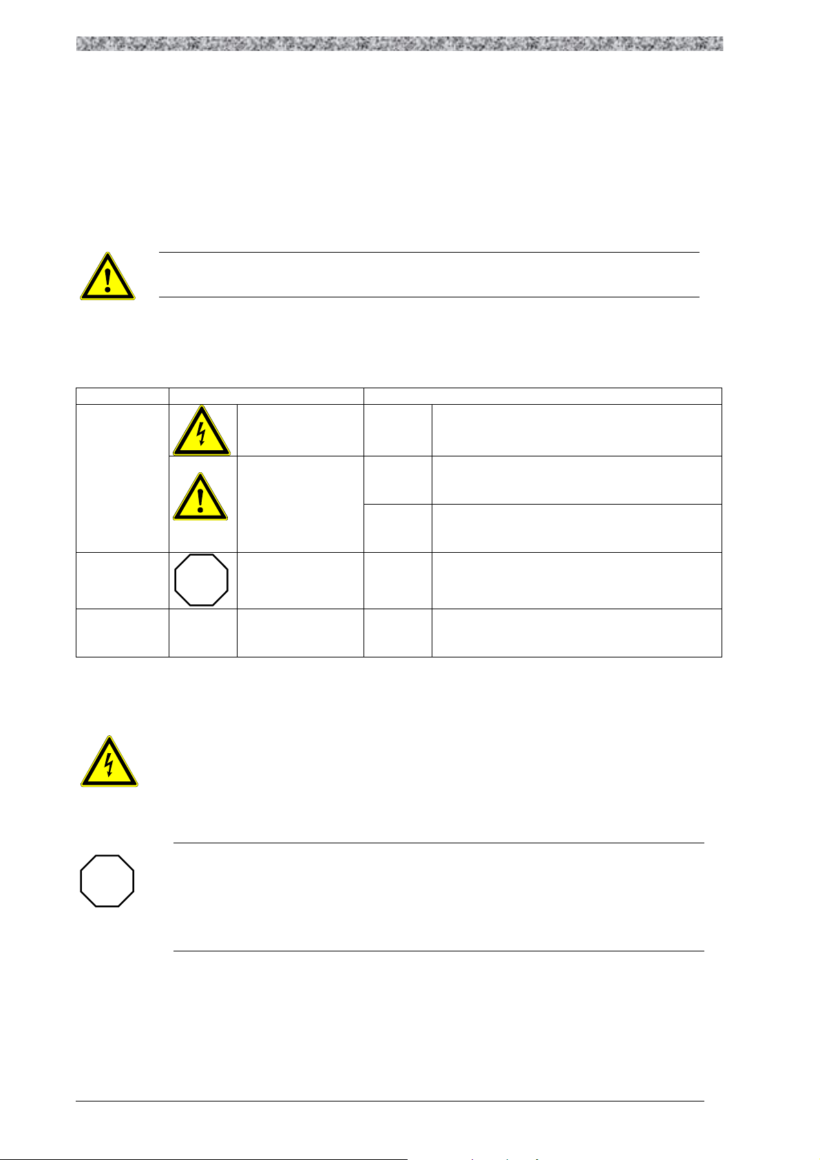
2.4 Layout of the safety information
• All safety notes have a uniform layout:
- The icon characterizes the type of danger.
- The signal word characterizes the severity of danger.
- The note describes the danger and suggests how to avoid the danger.
Signal word
Note
Icons used Signal words
Warning of
danger to
persons
Warning of
danger to material
electrical voltage
Warning of a general
danger
Danger!
Warning!
Caution!
Stop!
Warns of impending danger.
Consequences if disregarded:
Death or very severe injuries.
Warns of potential, very hazardous situation.
Possible consequences if disregarded:
Death or very severe injuries.
Warns of potential, hazardous situation.
Possible consequences if disregarded:
Light or minor injuries.
Warns of potential damage to material.
Possible consequences if disregarded:
Damage of the drive system or its environment.
Other notes
2.5 Residual hazards
Operator’s safety
After mains disconnections, the power terminals + and – remain live for
several minutes.
Protection of the device
Cyclic connection and disconnection of the supply voltage at terminals L1, L2
und L3, may overload the internal input current limitation:
Allow at least 1 minute between disconnection and reconnection.
Note!
This note designates general, useful notes.
If you observe it, handling of the power feedback
unit / drive system is made easier.
page 16 ELTROPLAN-REVCON
Page 18

2.6 General instructions
By these information to erectors and users of a plant hints on properties and
directions concerning the power feedback unit are given. These hints are not
entitled to completeness.
Special features in comparison towards a chopper
Unlike a braking resistor a power feedback device isn't a constant sink, but it's
dependent on the momentary characteristics of the supplying net. Commutation
brake downs and voltage-flicker in the net have an considerable effect to the
backward current of the device. In case of a short time voltage brake down the
Safety information
backward current has to rise correspondingly to feedback the demanded power-
amount. Does the level of the supply voltage sink for a longer time, the maxi-
mum feedback power is reduced.
If only one phase fails, the device is able to work on, but the current in the two
remaining conductors will rise up to 150% of the normal level.
ELTROPLAN-REVCON page 17
Page 19
(
)
i
REVCON
®
-
type
Power
DC-
capacitance
SVC
7-
45kW
100µF
70-
135kW
200µF
160-200kW
420µF
Safety information
Length of the DC-connection
The maximum inductivity of the DC-connection between output B6 bridge of
the inverter and the power feedback device mustn't exceed a certain level, as
this inductivity inducts an additional voltage to the DC-bus, when the IGBT’s
are switched off . To avoid an overload to the components of the power feed-
back unit, this additional voltage must not exceed 100V. Resulting from this
and other relevant characteristics of the power feedback unit (DC-capacity and
absolute maximum value of the grid current) the maximum inductivity
L
=
max
or equal than the sum of the DC-bus inductivity of the frequency inverter and
the conductor inductivity of the DC connection. The DC-bus inductivity of the
2
UC
∆⋅
GL
2
ˆ
can be calculated. This inductivity always has to be higher
frequency inverter has only to be considered, if it is placed between the inverter
B6 bridge and the power feed-back unit. The cables, which are normally used
for power applications, have an inductance per unit length of about 0,6µ H/m. If
the values of the input capacitance C, the during power backfeeding maximum
allowed rise of the DC-voltage ∆UGL =100V, the top level of the AC-current of
the device (=2xI
DC-bus ´choke L
be calculated with the following equation:
), the inductance per unit length L´ and the inductance of the
eff
are known the maximum longitude of the conductors can
ZKD
2
UC
l
max
∆⋅
=
2
ˆ
Li
⋅
L
ZKDGL
−
′
′
L
Typical capacitance of the DC-connection inside the power feedback unit :
Table 2.6.1
Example:
C=200µF, ∆UGL=100V, i=271A, a=80mm, r=8,5mm, µ0=1,257.10-6 H/m ⇒
l
=26m
max
For longer DC-Bus-wires additional capacitors have to be installed (please get
in contact with our application-department if the occasion arrises).
page 18 ELTROPLAN-REVCON
Page 20
Safety information
REVCON
0,4kV
G
STOP
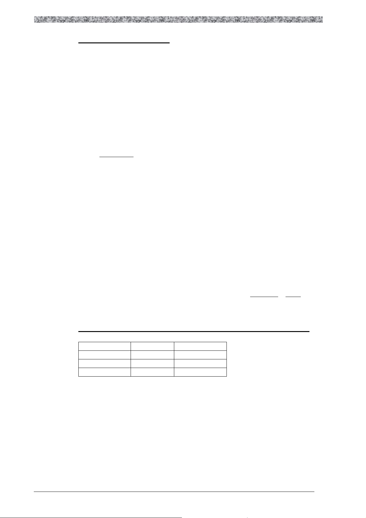
Operation on a generator
The usage of a power feedback unit within an island network (e.g. with an
diesel generator) is possible, but there are restrictive regulations concerning the
power limits.
100kVA
R
20kW
M
20kW
FU
M
Figure 2.6.1
Within a network, that is assembled like in figure 2.6.1, there are two addi-
tional restrictions: First the power of the motor connected to the inverter must
be lower than half of the nominal power of the generator. Second the total
amount of the power of the two other loads must be more than double of the
backfeed-power.
If these conditions aren't checked up a change from motory to generatory op-
eration may result in load shocks. These shocks are too dynamic for the voltage
regulator of the generator. The regulator reacts with an overshoot and as a re-
sult of this with an over voltage within the island network.
STOP!
Over voltages may cause serious damages to the connected frequency in-
verter and /or to the power feedback unit and to the other loads.
ELTROPLAN-REVCON page 19
Page 21
REVCON
Safety information
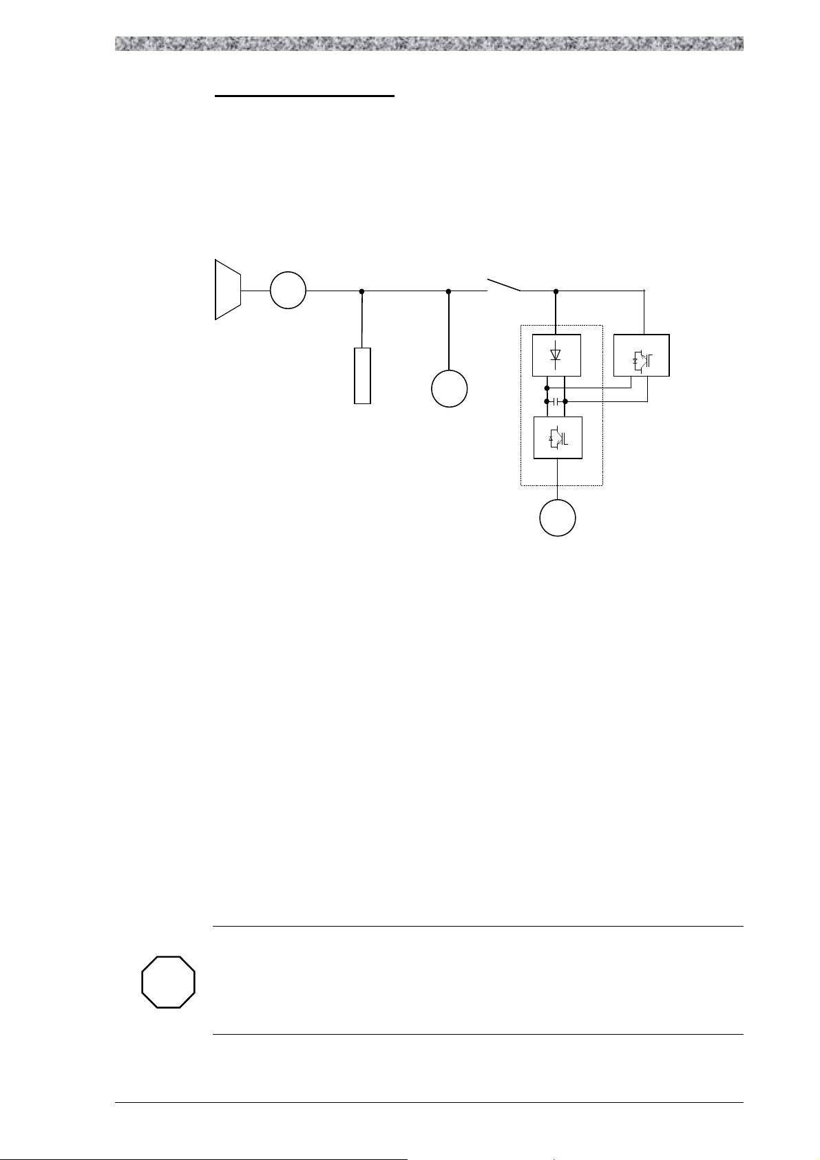
Operation on a transformer
If only a few loads operate within a network section the connected transformer
must be able to transport the in this section not used power back to the next
voltage level without producing a not allowed voltage increase inside the sec-
tion. Therefore the nominal power of the transformer has to be one and a half
higher than the backfed power out of the section, so that also the harmonic and
reactive components of the current can be transmitted. In the network section
displayed in figure 2.6.2 these conditions are checked up, even if the other
loads are switched off.
Is the backfed power in the order of the nominal power of the transformer, it's
impedance voltage has to be small enough (max. 6%) to limit the voltage in-
crease in the section.
The operation of the power feedback unit in combination with an adjusting
transformer (e.g. in the case of a braked slip-ring induction motor) is only al-
lowed, if the quotient ratio of feedback-power and nominal power is much
smaller than one
10kV
100kVA
Tr
0,4kV
20kW
R
M
20kW
M
FU
60kW
Figure 2.6.2
page 20 ELTROPLAN-REVCON
Page 22
Safety information
REVCON
Not allowed!
STOP
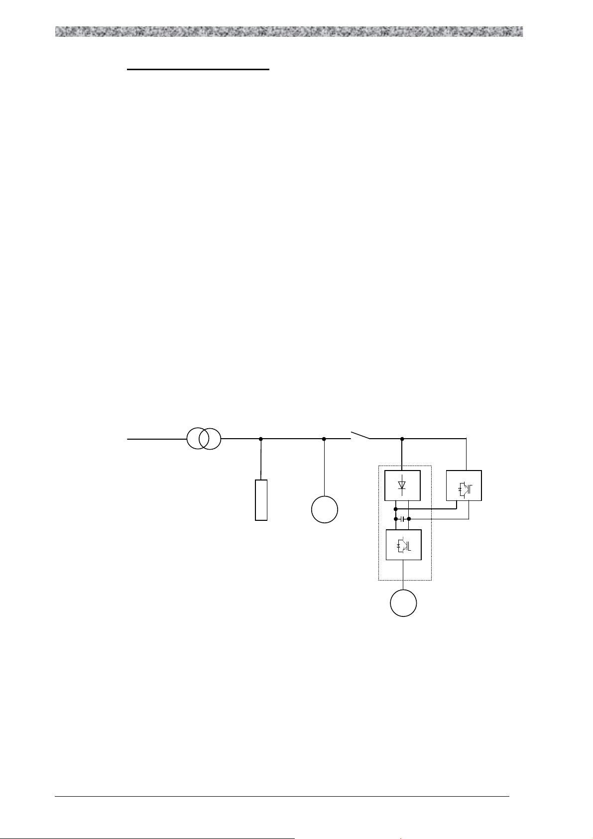
Placing of the commutation choke
If the frequency converter is connected to an external commutation choke, the
connection of the power feedback unit has to be done at it's network terminals
(figure 2.6.3). Is the connection done at the load terminals of the commutation
choke it's inductivity prevents the synchronising to the supplying net and the
induction voltage of the choke when it is switched of under load may result in
damages to the power feedback device.
STOP!
Over voltages may cause serious damages to the connected frequency in-
verter and /or to the power feedback unit and to the other loads.
Figure 2.6.3
FU
M
60kW
The same things apply to the also non-admissible pre-connection of further
commutation chokes.
ELTROPLAN-REVCON page 21
Page 23

∆U ∆U ∆U ∆U ∆U ∆U ∆
U
I
REVCON
Safety information
Line and contact resistances
The values of current carrying capacity of conductors refer to the most often
used copper conductors. Concerning to it's higher specific resistance
aluminium conductors must have greater dimensions.
Regardless of which conducting materials is used, the contact terminals of the
conductors have to be low resistive and their number has to be reduced to the
necessary minimum.
Too much or too high resistive terminals may result in a unsafe voltage magni-
fication during the power feedback operation.
Supplying
network
Figure 2.6.4
FU
M
Proceeding from a stable network with e.g. 400V nominal voltage and a back-
ward current of 80A, at a bad made terminal of 100mW a voltage of 8V is
dropped (A good made terminal has got a resistance of ca 1 mW.). During
backfeed operation at seven serial terminals at the net switch there results an
voltage of 456V.
page 22 ELTROPLAN-REVCON
Page 24

STOP
Safety information
STOP!
Over voltages may cause serious damages to the connected frequency in-
verter and /or to the power feedback unit and to the other loads.
Current capacity of copper conductors for frequency inverters and power
feedback operation
conductor cross section
(mm²) per phase
conductor radius
(mm)
fuse
(A)
max. permanent
current (A)
16 2,3 63 46
25 2,8 80 59
35 3,3 100 73
50 4,0 125 90
70 4,7 160 106
95 5,5 200 140
120 6,2 250 206
185 7,7 315 250
2x120 2x6,2 400 300
2x150 2x6,9 500 390
2x185 2x7,7 630 485
3x185 3x7,7 800 570
3x240 3x8,7 1000 740
4x240 4x8,7 1250 920
These values are based on a cable length of 100m and a maximum voltage drop of 5V..
Table 2.6.2
ELTROPLAN-REVCON page 23
Page 25

Supplying network
false
REVCON
Safety information
Connection of further loads
The connection of further loads ( e.g. cabinet ventilation or climatisation)
parallel to the frequency inverter / power feedback unit at a common circuit
breaker like in figure 2.6.5 is not allowed. If it's done nevertheless, in case of
tripping of the circuit breaker the connection to the network ( energy sink and
synchronising element for the power feedback unit) misses. The IGBT's now
switch the DC-voltage directly to the other loads. The resulting nearly rectan-
gular "net"-voltage drives a current through the loads, which level and form
depends on their impedance. Is the power consumption of the loads to small,
the DC-voltage and also the output voltage of the power feedback unit rises
during the backfeed operation. This increased voltage may damage all con-
nected components.
Figure 2.6.5
wrong
FU
M
60kW
M
page 24 ELTROPLAN-REVCON
Page 26

Safety information
Supplying network
REVCON
FFFF
STOP
STOP!
Over voltages may cause serious damages to the connected controller and
/or to the power feedback unit and to the other loads.
Figure 2.6.6
M
FU
FU
M
M
FU
60kW
TIP!
Same things apply to the structure like in figure 2.6.6. Even in this case it is
necessary to place a circuit breaker in each backfeeding current circuit.
ELTROPLAN-REVCON page 25
Page 27

Safety information
Unchoked compensation plants and resonance rise
Compensation plants are used in the centre of the power supply of a company.
Disturbances or damages at these plants have effects on the power supply and
may result in interrupted production processes.
Although this is no longer state of the art, many compensation plants are in op-
eration without any choking. The problems which result from a usage of such
an unchoked compensation plant are manifold:
- direct resonance
- resonance rise
- switching transients or
- impairments of centralized ripple systems
The fact, that a company produces back effects to the power supply is not the
only reason for the creation of resonance. Decisive for the risk, to generate a
resonance is the compensation power at the medium voltage transformer. The
higher this power is, the higher is the risk of resonance. The second important
factor is the harmonic load of the medium voltage level. This harmonic load is
transmitted via the transformer and causes effects on the low voltage level.
Most often the limits were exceeded for the 5th harmonic component.
page 26 ELTROPLAN-REVCON
Page 28

3 Technical data
3.1 Characteristics
• Small compact housing
• Braking power of controller is fed back into mains
• Power range 4kW to 350KW
• Up to 4 units can be paralleled (more on request)
• DC-bus coupling of several controllers possible
• IGBT power modules with high efficiency and high service reliability
• Self synchronising
• Overload protection during backfeeding operation
• Supervision of mains voltage, phase sequence and temperature
Technical data
• High efficiency
• High dynamic braking processes are possible
• User-friendly commissioning – no adjustment necessary
• Including buit in harmonic filter SKS-R
ELTROPLAN-REVCON page 27
Page 29

Technical data
3.2 General data / application conditions
Area Values
Permissible temperature range* During transport of the unit: -25°C...+70°C (to VDE 0160)
During storage of the unit: -25°C...+55°C (to VDE 0160)
During operation of the unit: 5°C... +40°C without power derating
40°C...+55°C with power derating
Humidity class* Humidity class F without condensation ( 5% - 85% relative humidity)
Installation height h*
H ≤ 1000 m a.m.s.l. without power derating
1000 m a.m.s.l. < h 4000 m a.m.s.l. with power derating
Air pressure* 86kPa – 106kPa to VDE0875 part 11 and prEN55082
Degree of pollution VDE 0110 Part 2 degree 2
Noise immunity EN 61000-4-4 degree 4
EN 61000-4-2 degree 3
EN 50082-2 criterion A
Insulation strength Overvoltage category III according to VDE 0110
Packaging DIN 55468 for transport packaging materials
Type of protection IP 20
Approvals CE: Low-Voltage Directive
*climatic conditions according to class 3K3 (EN 50178 Part 6.1)
page 28 ELTROPLAN-REVCON
Page 30

3.3 Rated data
3.3.1 Power feedback unit
REVCON type
Nominal range of the
interlinked mains voltage
Tolerance of the
interlinked mains voltage
Mains frequency
Overload capability
SVC(S) 400V
UN[V]
UN[V]
fN[Hz]
Technical data
380 ≤ UN ≤ 415
342 ≤ UN ≤ 456
50 ± 2 %
ca. 1,2 x Irms (dynamic)
Efficiency
Power factor*3
Total harmonic distortion*
3
η[%]
cosϕ
THDI
Ca. 96 % (4 % therm. losses)
∼ 1
< 16%
[%]
*1 need of airflow
m³ / h
a) SVCS 7-400, 13-400, 22-400, : 200
b) SVCS 33-400 : 350
Power derating
[%/K]
[%/m]
40°C < Ta < 55°C ⇒ 3%/K
1000m a.m.s.l.< h ≤4000m a.m.s.l. ⇒ 5%/1000m
Table 3.3.1.1
*1 depending on the size of the unit ( nominal power and nominal voltage)
2
*
3
*
alternative case-type with minor changed dimensions
at nominal current
ELTROPLAN-REVCON page 29
Page 31

FFFF
Technical data
3.3.2 Current load
Nominal voltage 400V
AC
REVCON ® - Typ
SVCS 7-400-1-0 11 A 13 A
SVCS 13-400-1-0 20 A 24 A
SVCS 22-400-1-0 32 A 38 A
SVCS 33-400-1-0 48 A 58 A
Table 3.3.2.1
max. current I
rms
NOTE!
To calculate the correct value of regenerating power it is necessary to note, that
the real momentary regenerating power is dependent on the real existing main
circuit voltage at any time. To calculate the regenerative power the following
DC
max. current I
formula should be used:
P = U
eff
· I
· √3 · cosϕϕϕϕ (during regenerative operation : cosϕ = 1)
eff
The maximum possible regenerative power is calculated based on the momen-
tary rms mains voltage and the maximum rms current of the respective device.
Example:
Model SVC(S) 45 with rated feedback power of 45kW , maximum rated rms
current 65A (refer to technical data), nominal mesh voltage rating e.g. 400V.
From that results: P=400V x 65A x √3=45033W, that’s about 45,0kW
If the momentary rms mains voltage is only 395V or even lower for a short
time, the maximum possible regenerative power is reduced as well:
P = 395V x·65A x √3 = 44470W, that’s about 44,5kW.
page 30 ELTROPLAN-REVCON
Page 32

Technical data
3.3.3 Allowed operating data with max. braking power
− Devices of product line REVCON® SVCS 7-XXX-1-... without forced cooling have an al-
lowed operating duration of 100%.
− Devices of product line REVCON® SVCS 13-XXX-1-... without forced cooling have an
allowed operating duration of 50% (referring to a cycle time of 10 min.). With forced cool-
ing they have an allowed operating duration of 100%.
− Devices of product line REVCON® SVCS 22-XXX-1-... with forced cooling have an al-
lowed switch on duration time of 50% (referring to a cycle time of 10 min.).
− For the devices from product line REVCON® SVCS 33-XXX-1-... the following thermal
limited load graphs are valid.
ELTROPLAN-REVCON page 31
Page 33

REVCON
Technical data
3.3.3.1 Thermal limited load graphs
By means of these thermal limited load graphs you can find out the max. switch-on-time depending on the needed braking power. The curves are valid for a max. cooling air temperature
of 35°C (95°F).
Example of an application:
10
min
braking
time
100 % constant power: 26 kW
9
8
7
SV(C
45-XXX-1-...
))))
33 kW
6
5
4
2
3
1
2
1
2
0
0 1 2 3 4 5 6 7 8 9 10 11
Diagram
3.3.3.1.1
1
intermission time
45 kW
min
Example : necessary braking power : 33 kW
braking duration : 2 min.
time between two brakes : 5 min.
Evaluation: In this case the point of intersection of braking time and intermission time is
below
the thermal limited power graph in the allowed area (with forced cooling).
Remark: Without forced cooling, the intermission time is 8 minutes.
Example : necessary braking power : 45 kW
braking duration : 3 min.
time between two brakes : 3 min.
Evaluation: In this case the point of intersection of braking time and intermission time is
above
the thermal limited power graph. That means this operation cycle is not allowed.
Remark: In case of an intermission time of e.g. 3,5 min. this operation cycle would be
allowed again.
page 32 ELTROPLAN-REVCON
Page 34

Thermal limited load graphs:
REVCON
SV(C) 33-XXX-1-...
Technical data
10
min
100 % constant power with fan: 21,5 kW
9
braking
time
8
7
6
5
4
3
2
1
0
0 1 2 3 4 5 6 7 8 9 10 11
Diagram 3.3.3.1.2
27 kW with fan
33 kW with fan
27 kW without fan
33 kW without fan
intermission time
min
ELTROPLAN-REVCON page 33
Page 35

SVCS
7-
400-1-0 Siba 50 179 06 20A 660V 10*38mm
CS M5
25mm²
SVCS
13-
400-1-0 Siba 50 124 06 30A 690 V 14x51mm
CS M6
35mm²
SVCS
22-
400-1-0 Siba 50 124 06 50A 690 V 14x51mm
CS M6
35mm²
SVCS
33-
400-1-0 Siba 50 140 06 80A 690 V 22x58mm
CS M6
35mm²
Technical data
3.3.4 Fuses and wire cross sections
The power feedback unit is connected to mains supply via the terminals L1-L3 at the
commutation choke and PE at the heatsink. Mains fuses must be designed according to the
current load capacity of the supply wire.
3.3.4.1 Series fuses
Semiconductor fuses have to be connected in series with the power feedback unit as following
tables (refer to figure 4.4.1.1.1 position 1). The listed manufacturer is recommended, but natu-
rally also comparative fuses of other manufacturer (e.g. Jean Müller, Ferraz, Bussmann) are
suitable.
REVCON ® - type
max. fuse AC
Table 3.3.4.1.1
ES ≅ end sleeve for strands
CS ≅ cable socket with drill hole for M6 / M8 / M10
* at the copper lug of the commutation choke.
** at the fuse holder respective disconnector
Connection terminal and max.
cross section of the supply line *
page 34 ELTROPLAN-REVCON
Page 36

Technical data
SVCS
7-
400-1-0 Siba 50 124 06
2
0A 690 V 14x51mm
ES 10mm²
SVCS
13-
400-1-0 Siba 50 124 06 50A 690 V 14x51mm
ES 10mm²
SVCS
22-
400-1-0 Siba 50 140 06 63A 690 V 22x58mm
ES 35mm²
SVCS
33-
400-1-0 Siba 50 140 06 80A 690 V 22x58mm
ES 35mm²
STOP
3.3.4.2 Internal fuses
The power feedback unit is equipped with semiconductor fuses according to the following ta-
bles (refer to figure 4.4.1.1.1. position 7). The listed manufacturer is recommended, but natu-
rally also comparative fuses of other manufacturer (e.g. Jean Müller, Ferraz, Bussmann) are
suitable.
Table 3.3.4.2.2
REVCON ® - type
Stop!
If semiconductor fuses (figure 4.4.1.1.1 position 1 and 7) trip, please get in
contact with ELTROPLAN-REVCON immediately, as possibly further protec-
tive measures have tripped. If internal fuses are exchanged, please verify, that
only the original types are used for replacement.
Warning!
Before replacing a fuse, switch off all voltages!
DC-fuses
(use fast acting semiconductor fuses only)
Connection terminal and max. cross
section of the supply line **
ELTROPLAN-REVCON page 35
Page 37

Technical data
3.3.5 RFI-filter
To observe the EMC-rules. In accordance with figure 4.4.1.1.1 a radio fre-
quency interferences filter class A can be preconceived to the REVCON unit.
In tables 3.3.5.1 to 3.3.5.5 the power feedback units are assigned to the corre-
sponding RFI-filter types.
REVCON ® - type
SVC(S) 7-400-1-0 RF-SVC 7-400 1
SVC(S) 13-400-1-0 RF-SVC 13-400 1
SVC(S) 22-400-1-0 RF-SVC 22-400 1
SVC(S) 33-400-1-0 RF-SVC 33-400 1
Table 3.3.5.1
Order designation for filter
Case type
3.3.6 SKS-module
To decrease the low frequency harmonic back effects to mains a filter module
REVCON SKS-R is built into the power feedback unit .
page 36 ELTROPLAN-REVCON
Page 38

4 Installation
4.1 Mechanical installation
4.1.1 Important hints
• Use the power feedback units as build-in devices only!
• Observe free spaces!
- Several power feedback units in one cabinet may be installed next to
each other without spacing.
- Keep a horizontal distance of at least 70mm to other components and to
the cabinet walls.
Installation
- Keep a vertical distance of at least 150mm to other components and to
the cabinet walls.
• Ensure that there are no obstacles in the way of the cooling air input and output.
• If the cooling air is polluted (dust, dirt swirl, grease, aggressive gas ) so that the
function of the power feedback unit may be impeded
- Take sufficient countermeasures, e.g. separate cooling air, mounting of
air filters, periodical cleaning.
• Do not exceed the ambient temperature permissible during operation.
Provided mounting position
The power feedback unit has been designed for vertical wall mounting (± 15°)
only. Mounting is allowed only on a flat surface without using any kind of spac-
ers. This kind of mounting is necessary to guarantee the right way for the cooling
air. A power loss of 3 % from the max. nominal power rating has to be calculated.
Air-temperature may not exceed 40 °C near the unit. Air-in- and air-out-openings
at the top and the bottom of the unit may not be concealed by installation materials
such as cable ducts or other equipment. Keep a distance of min. 15 cm to the air-
in- and air-out-openings and a distance of min. 7 cm to beside mounted parts or
cabinet-walls.
ELTROPLAN-REVCON page 37
Page 39

Installation
4.2 Dimensions
4.2.1 Power feedback unit
REVCON ®
Type
SVCS 7-400-1-0 500 - 245 272 315 - 260 80 -- -- 25
SVCS 13-400-1-0 500 - 245 272 315 - 260 80 -- -- 30
SVCS 22-400-1-0 500 - 245 272 315 - 260 80 -- -- 35
SVCS 33-400-1-0 700 - 245 272 315 - 260 80 -- -- 40
Table 4.2.1.2
.
H
(mm)
H1
(mm)
H2
(mm)
B
(mm)
B1
(mm)
T
(mm)
T1
(mm)
e
(mm)
f1
(mm)
f2
(mm)
f3
(mm)
weight
(kg)
page 38 ELTROPLAN-REVCON
Page 40

4.2.1.1 Dimension diagrams
1. SVCS 7-400-... to SVCS 22-400...
Installation
ELTROPLAN-REVCON page 39
Page 41

Installation
2. SVCS 33-400-...
f2
Cooling airflow out
f2
Cooling airflow in
REVCON
H
7
f1
all cableinputs from bottom
B
B
f
1
T
e
1
page 40 ELTROPLAN-REVCON
Page 42

Installation
4.2.2 RFI-filters
The radio interference filter of case-type 1 and 2 are mounted in footprint-housings, which
could be placed between cabinet-wall and power feedback unit.
The radio interference filter of case-type 3 and 4 are mounted in housings, which should be
placed beside the power feedback unit.
The power feedback units were fixed with screws M6 , the RFI-filter with screws M8.
4.2.2.1 Dimension diagrams
1. Diagram Case 1
ELTROPLAN-REVCON page 41
Page 43

Installation
2. Diagram Case 2
3. Diagram Case 3
page 42 ELTROPLAN-REVCON
Page 44

4.3 Electrical installation
STOP
4.3.1 Operator’s safety
Danger!
After mains disconnection, the DC-bus terminals of the power feedback unit
remain live for several minutes! The exact time, till this voltage has decreased
to a not dangerous value is dependent on the used controller and has to run
down before any service operations or similar activities are started.
The exact values have to be cross checked with the documentation of the con-
troller.
Installation
Replace defective fuses by the regular types (chapter 3.3.3.2) only and without
any live voltage.
4.3.2 Protection of the power feedback unit
Stop!
The power feedback units contain electrostatic sensitive devices (ESSD).
During working at the terminals the personnel has to observe the rules of the
international standard IEC 747-1 chapter 9. Basically before starting the works
the personnel has to free itself from electrostatic voltages:
Discharge yourself by touching the PE-screw of the housing or another
grounded surface in the cabinet.
ELTROPLAN-REVCON page 43
Page 45

Installation
4.3.3 Mains types / Mains characteristics
Observe the restrictions in accordance to the respective mains type!
If you want to run power feedback units at mains types, which are not listed in
the table below please consult our technicians.
VDE conformal
mains type
With grounded star point
Operation of the
power feedback unit
Allowed
With isolated star point After consulting the manufacturer and
possible modification of the unit allowed
With grounded active wire After consulting the manufacturer allowed
Table 4.3.3.1
4.3.4 Specifications of the used wires
• The used wires have to be compliant with the specifications on site ( e.g.
UL or UL-c)
• The regulations about the minimum cross section of PE-wires have to be
observed!
• The effectiveness of a screened wire is dependant on
Remark
Observe the technical
data of the unit
- a good screen connection
- a low screening impedance:
Use screens tin- or nickel-plated copper screens only!
- the swamp factor of the screen mesh:
at least 70% to 80% with a swamp angle of 90°
• Protect the mains wires of the power feedback unit with the provided wire
protection fuses.
page 44 ELTROPLAN-REVCON
Page 46

4.4 Connection
STOP
After removing the lateral screws and the cover of the housing the connection
terminals are accessible. The wires should be passed through the metal glands
in the flange sheet.
Stop!
When picking up the cover don’t damage the wires, which lead to the display!
4.4.1 Power connection
Fusing (also refer to chapter 3.3.4)
Installation
• The specifications of chapter 3.3.4 (fuses and wire cross sections) are rec-
ommendations and refer to the operation
– in cabinets and machines
– installation in cable ducts
– max. ambient temperature +40°C.
• When choosing the cross section of the wire the voltage drop under load
should be considered (refer to chapter 3.4)
• Protection of the wires at mains side (L1, L2, L3):
– by commercial wire protection fuses.
– fuses have to be compliant with the relevant standards on site.
– rated voltage of the fuses have to be compliant with the voltage on site.
• Protection of the power feedback unit at mains side (L1, L2, L3):
– by commercial semiconductor fuses.
– fuses have to be compliant with the relevant standards on site.
– rated voltage of the fuses have to be compliant with the voltage on site.
• Protection of the power feedback unit at DC side (+UG, -UG):
– fuses are part of the power feedback unit (refer to chapter 3.3.4.2).
The erector/user of the plant bears the responsibility for the observance of
further relevant standards (e.g.: VDE 0113, VDE 0289 and so on).
ELTROPLAN-REVCON page 45
Page 47

FFFF
Installation
Connection
• All connections should be as short and low-impedance as possible.
• For the observance of the EMC-guideline (in accordance to actual stan-
dards like VDE 0160 and EN 50178) screened wires have to be used.
• Connect the mains supply wires at the terminals L1, L2, L3 (at the mains
choke) of the power feedback unit. Only three phase connection is allowed.
• A defined phase sequence (clockwise rotation field) must be observed at
the main circuit connection of the power unit. The power feedback unit is
equipped with a phase-sequence control unit. In case of an incorrect rota-
tion field an error message is displayed via LED as follows: "rotation field
failure" or "phase failure". In this case two phases, connected to the power
unit, have to be exchanged.
• Connect the earthing wire of the supply cables to the earthing screw of the
power feedback unit.
• The wires for the DC-bus coupling between controller and power feedback
unit have to be connected to the DC-fuse holder. It is absolutely necessary
to observe the correct polarity.
Tipp!
Interchanging of + (PLUS) and – (MINUS) avoids the correct function of the
power feedback unit.
page 46 ELTROPLAN-REVCON
Page 48

4.4.1.1 Wiring schematic
Controller
radio inter
-
ference filter
3
PE U V W
L1 L2 L3
c
ontrol
8 11 12
X2
X2
1
operation
+24 V
-
OFF
RESET
7
4
5
8
PE
N
L3
230V
L1
N
L1
L2
1
2
3
Installation
6
1
N
PE
L1 L2 L3
+
REVCON SVCS...(type)
- -
Error
2
relay
4
ext.
+
M
~
Figure 4.4.1.1.1 Wiring schematic of the power feedback unit REVCON SVC(S) and one ore more
Remark:
This is an wiring example. Special features of a application (e.g. installation of a PLC) may
require modifications of the wiring of the terminals X2.1 ... X2.12 .
ELTROPLAN-REVCON page 47
controllers
Page 49

Installation
Legend for figure 4.4.1.1.1 (REVCON
SVCS)
1. Fusing in accordance with controller manual.
2. It is not allowed to connect any other devices except the frequency inverter and the
power feedback unit behind the main magnetic switch.
Danger
If this is not observed, you take the risk that, in the case of switching off the
mains during feed back the power, the voltage in that sector may rise up to a
dangerous level. This may destroy the connected devices and perhaps also the
inverter and/or the power feedback unit. To avoid such situation, the power
feedback unit is equipped with an overvoltage switch off, but nevertheless this
hint should be observed!
3. Fusing in accordance with power feedback unit manual. This may be left our, if at
position 1 semiconductor fuses or full range fuses are used and if after 1 the cross
section of the wires is not reduced.
4. Cross section in accordance with the relevant VDE-rules.
5. Fusing (230 V supply, <2A current input) in accordance with DIN VDE 0298 or
short circuit proof wiring.
6. Design of the mains choke in accordance with controller manual (possibly not
applicable, if already installed inside the controller).
7. At these terminals one ore more controllers (even with different power ratings)
may be attached, like it shown in figure 4.5.1. Even if several controllers are at-
tached, the wires have to be as short and low impedance as possible!
8. The „ON“ or „RESET“ signal may be initiated via terminals 9 and 10 or 11 and 12:
Terminals 9 and 10: potential free contact (short time contact)
Terminals 11 and 12: positive pulse (12-24 V DC); practicable e.g. via PLC
(terminal 11 +, terminal 12 -).
page 48 ELTROPLAN-REVCON
Page 50

Installation
4.4.2 Fan supply
Some power feedback units are equipped with two terminals (blue terminal =
neutral [N] , grey fuse terminal = phase [L]) for the supply of the internal
fan(s). The fuse inside the fuse terminal is installed for internal wire protection
and of the following type 2A medium 500V 5x30mm.
4.4.3 Control wires
• Connect the control wires to the terminal row X2 at the control board of
the power feedback unit.
• Don’t parallel control wires to interfering power wires.
• Connect the screening of the control wires with an as big as possible sur-
face to the metal cable glands of the flange.
4.4.4 Control functions
The control terminal strip is placed on the control board and is indicated with
X2. It is fitted with a plug-in device for easy handling (see figure 4.4.4.2).
The control board must always be designed for the respective main circuit volt-
age. Therefore the main circuit voltage (230 V, 380 V - 415 V, 440 V - 480 V,
500 V or 690 V) must be declared with every order. This is also necessary for a
possible exchange of the device.
From the control terminal strip the operating condition or rather the collective
error can be connected to extern. There is also the possibility to execute the ex-
ternal reset or the switch-functions and to connect them with the controller or
the PLC.
ELTROPLAN-REVCON page 49
Page 51

X1
X2 X4
X3 X5
X5
X8
Installation
Space diagram of the control board REV 1.4.X
J4
terminal X3
connection to
driver board
terminal X5, X8
option
TR1
TR6
L4
TR4
J5 J3
J6
REVCO N
V. 1.4.3
J7
J8
TR2
J1
LD5
LD3
LD4
LD2
LD1
TR3
TR5
terminal X1
synchronisation to
mains supply
Figure 4.4.4.1
page 50 ELTROPLAN-REVCON
terminal X2
terminal X4
connection to
type of
control board
(example)
signalling board
LED-messages
green: operation
1. red: phase failure
2. red: U
orange: overtemperature
yellow: collective error
/ overcurrent
CE
ext. messages
and controlling
Page 52

Terminal usage:
8
external
OFF
ON/RESET
terminal 5 and 6 intern connected
to the temperature supervision
collective error
relay
X2
1
2
3
4
5
6
7
Installation
9
10
11
12
Figure 4.4.4.2
Terminals 1-4 (refer to figure 4.4.4.2)
These terminals are contacted to two potential free (SELV) relay contacts (one
NOC and one NCC) with a maximum current load of 5 A AC or 3 A DC. It is
not allowed to connect other voltage types than SELV!
In figure 4.4.4.2 the relay is displayed in rest position.
The relay toggles, if:
+
-
ELTROPLAN-REVCON page 51
1.) power supply is o.k.,
2.) no error present,
and after perhaps an ON-signal has been released.
If an OFF-signal has been released, an collective error is display as the relay
toggles.
Page 53

Installation
Terminals 5 and 6
These terminals are already used for the internal temperature supervision of the
heat sink.
Terminals 7 and 8
(use screened wires only, max length)
OFF-signal
These terminals may be used for an external OFF-signal (NOC, short time
contact) to stop the power feedback unit.
Note!
The OFF-signal stops the backfeeding immediately. If this is done in regen
mode, the controller would trip because of too high DC-bus voltage right
afterwards.
Terminal 11 and 12
(used screened wires only)
These terminals may be used for an external ON-signal (external voltage 12 –
24V DC [e.g. from PLC], short time pulse) to start / reset the power feedback
unit.
(connect „Plus“ to terminal 11, „Minus“ to terminal 12)
page 52 ELTROPLAN-REVCON
Page 54

4.5 Application example
Installation
figure 4.5.1
Within greater plants several power feedback units may be coupled. Figure
4.5.1 shows an example of a windage plant with some possible combinations.
The operation of several inverters at one common DC-bus allows to reduce the
amount of power feedback units. On the other hand several power feedback
units may be coupled to transmit more power. It's also possible to drive several
motors at one inverter, as they react, seen from the DC-bus (and that's, what the
power feedback unit sees), like one big motor.
To proportion such a plant it is important to look at the worst case. The maxi-
mum feedback power of the power feedback unit has to be higher as or , at a
minimum, equal to the total amount of the braking power of the connected mo-
tors.
ELTROPLAN-REVCON page 53
Page 55

•
•
•
•
•
Installation
4.6 Installation of a power feedback unit in a
CE-typical drive system
General
Assembly
Filters
Screening
Earthing
The user is responsible for the compliance of his application with the EC directives.
- If you observe the following measure you can be sure that the drive system will not
cause any power-feedback-unit-caused EMC problems, i.e. comply with the EMC
Directive when running the machine.
- If devices which do not comply with the CE requirement concerning noise immunity
EN 500082-2 are operated close to the power feedback unit, these devices may be interfered electromagnetically by the power feedback units.
Connect the power feedback unit and the RFI-filter to the grounded mounting plate with a
wire of large cross section as possible:
– Mounting plates with conductive surfaces (zinc-coated or stainless steel) allow per-
manent contact.
– Varnished boards should not be used for installation in accordance with EMC.
• If you use several mounting plates:
– Connect as much surface of the mounting plates as possible (e.g. with copper bands)
• Ensure the separation of power and control cables.
• Cable guides as close as possible to the reference potential. Unguided cables have the same
effect as aerials.
Use RFI filters which are assigned to the power feedback unit.
RFI filters reduce impermissible high frequency interference to a permissible value.
Metallic cable glands ensure a big-surface connection between screen and housing
• If the screened wire are interrupted at relays or terminals:
- Connect the screens of the wires with a big surface to the mounting plate.
• If the mains wires between RFI-filter and power feedback unit are longer than 300mm:
- Use screened mains wires
- Connect the screen direct at the controller / power feedback unit and at the RFI-filter to
the mounting plate.
• Screen the control wires:
- Connect the screens on the shortest possible way to their terminals.
All metallic conduction components (power feedback unit, controller,
RFI-filter) have to be connected to one common earthing point (PE-bus bar).
• Observe the in the safety guidelines defined minimum cross sections:
- For EMC not the cross section, but the surface of a wire and the contact to the mount-
ing plate is important for the function.
page 54 ELTROPLAN-REVCON
Page 56

Installation
Power feedback units are electrical units for usage in industrial and commercial
plants. In accordance with the EMC guideline 89/336/EEC it is not obligate to
mark these units, as in the sense of the EMC guideline and the EMC law they
are components to be mounted by an competent electromechanical engineer
and cannot be used stand alone. The proof of the observance of the protective
aims of the EMC guideline has to be carried out by the erector / user of the ma-
chine / plant. If the by ELTROPLAN-REVCON released RFI-filters are used
and the following measures and installation guidelines are observed, the adher-
ence to the prescribed data is cleared.
In combination with the related RFI-filter the power feedback unit has been de-
signed for the usage in ambients of the limit class „A“ („B“ on request).
Definition in accordance with basic standard:
• EN50081-2 for emission
• EN50082-2 for immision
4.6.1 Installation
Appropriate design of pant and cabinet.
To avoid noise incoupling lay
a) mains/supply wires
b) motor wires of controllers / servo amplifiers
c) control- and data wires (small voltage range < 48 V)
with a distance of at least 15 cm between each other.
To obtain low resistive HF-connections, grounding, screening and other metal-
lic connections (e. g. mounting plates, mounted units) have to be done with a as
big as possible surface to metallic ground. Use grounding and potential equali-
sation wires with as big cross section as possible (min. 10mm²) or thick
grounding tapes.
ELTROPLAN-REVCON page 55
Page 57

Installation
Use copper or tinned copper screened wires only, as steel screened wires are
not suitable for high frequency applications. Connect the screen with metal
clamps or metal glands to the equalisation bars or PE-connections. Don’t
elonger the screen with single wires!
If external RFI-filters are use, these have to be mounted not more than 30cm
away from the noise source and with a very good, low resistive based contact.
Inductive switching units (relay, magnetic contactor and so on) have to be
equipped with varistors, RC-circuits or suppressor diodes always.
All connections have to be as short as possible and must lay as close to the
ground potential as possible, as free hovering wires act like aerials.
Avoid wire loops in all wires. Connect unused wires to ground at both ends.
If unscreened wires are used, intertwist the pairs to attenuate unsymmetrical
noise.
4.6.2 Connection of a RFI-filter
The following figure shows mounting and connection of an external RFI-filter.
Filtered wire to controller
Gefilterte Leitung zum
Frequenzumrichter
Funkentstörfilter flächig
RFI-filter connect to mounting
plate with big surface
mit der Montageplatte
verbunden
Potential equalisation to
Potentialausgleich zur
building ground
Gebäudeerde
Mains wire
Netzleitung
Screen busbar connected to mounting
Schirmschiene aus Kupfer, flächig
plate with big surface
mit der Motageplatte verbunden
Additional grounding bond
Zusätzliches Masseband
Mounting plate
Montageplatte
Connected protective wire
Schutzleiter angeschlossen
page 56 ELTROPLAN-REVCON
Page 58

4
8
3
6
Installation
4.6.3 Design of an EMC-conformal cabinet
7
14
1
12
15
14
5
6
9 10
16
2
7
11
4
17
9
13
1. Cabinet 8. DC-bus wiring
2. Wiring between RFI-filter with power feedback unit (DC)
and controller 9. Mounting plate (common star point)
3. RFI-filter 10. Potential equalisation
4. mains supply wire 11. additional earthing wire
5. Wiring between RFI-filter 12. power feedback unit
and power feedback unit: 13. mains connection
cross section in accordance with fusing 14. PLC
or short circuit proof! 15. Controller
6. motor wiring 16. mains fuses
7. control wiring 17. mains magnetic switch
ELTROPLAN-REVCON page 57
Page 59

Installation
4.6.4 Remarks
Generally a system should be divided in an area for power electronics and an
area for control electronics. This is not only important, if the system is
mounted in one cabinet, but even also if it is spread over several cabinets. As
of the strong noise emission of the power wires it is recommended to mount a
screening wall. This wall must have a low resistive contact to the frame or the
mounting plate (remove lacquer!).
The installed power feedback unit and the connected RFI-filter must form an
integrated whole, i.e. they have to be connected via the mounting plate without
an isolating lacquer.
The connection wire between power feedback unit and RFI-filter must be
screened. At both ends the screen has to be connected to ground. The wire
should not be longer than 300mm.
The mounting plate of the power feedback unit should be the star point for the
whole grounding and screening of the machine or plant. If the drive or other
components of the plant cause interference, the HF connection of these compo-
nents is bad. This could be improved by an additional potential equalisation.
By using RFI-filters the leakage current is increased. As the leakage current is
higher than 3,5 mA, one of the following conditions must be fulfilled:
-
Cross section of the protective wire must be at least 10 mm² CU.
-
Supervision of the protective wire by an module, which trips in case of
an fault.
-
Install a second wire in parallel to the protective wire via separate ter-
minals. This wire must be conformal with VDE 0100 / part 540.
page 58 ELTROPLAN-REVCON
Page 60

4.6.5 Installation of control wires
The screen of digital signal wires, which are not connected to terminals, has to
be connected to the screen bars to decrease the impedance of the screen.
The screen of digital signal wires, which are connected to terminals, has to be
connected with as big surface as possible to ground.
If the screen is grounded via a single wire, the noise discharge is getting worse
by 70%.
Installation
For screen connection commercial cable clamps are suitable.
If unscreened signal wires are used, install only twisted pair wires.
ELTROPLAN-REVCON page 59
Page 61

STOP
STOP
Installation
5 Commissioning
Stop!
Prior to initial switch-on of the power feedback unit check the wiring for com-
pleteness, short-circuit and earth fault.
Stop!
If the wiring is not correct, a non-intended operation of controller and/or power
feedback unit is possible.
5.1 First powering up
1. Switch on mains supply :
- The power feedback unit is ready for operation after ca. 1s
2. Check the readiness for service of the power feedback unit:
– If only the green LED is on:
power feedback unit is ready for service.
– If beside the green LED also other LED’s are on:
A disturbance is present. Before proceeding with commission-
ing, re move the disturbance (refer to chapter 7 "Troubleshoot-
ing”).
3. Check the readiness for service of the controller:
– Proceed in accordance with the controller manual.
page 60 ELTROPLAN-REVCON
Page 62

6 Configuration
The coding of the jumpers enables different driving possibilities and different
internal functions in accordance to specific error messages.
In the following different definitions are explained which result from the spe-
cific possibilities of coding!
a) „Autostart“
Autostart means that the device is starting with a delay-time of about 1 sec. af-
ter connecting mains voltage automatically ("automatically switch-on").
Coding via jumper, see figure 4.4.4.1:
Configuration
J1 closed : Autostart
If the unit should not start automatically despite the phase failure control is dis-
abled, during the switch on process the terminals 7 and 8 have to be bridged till
4 s after switching on. To start the backfeeding afterwards a short impulse has
to be given on the RESET input.
b) „Switch on“ - „Switch off“
„Switch off“ means that the driving of the semiconductors and the power feed-
back will be interrupted. A braking operation of the frequency inverter with
power feedback is no longer possible.
„Switch-on“ is the activation of driving the semiconductors.
c) „Storage“
The unit is equipped with an error storage where special failures can be as-
signed to. Stored error messages have to be confirmed by RESET or interrup-
tion of mains supply. "Storage" always leads to a "switch-off" and to a collec-
tive-error-relay tripping.
ELTROPLAN-REVCON page 61
Page 63

STOP
Configuration
d) Reset
After the failure is removed, a stored error has to be reset by pushing the
RESET-button or rather by switching-off and on again the main circuit voltage
(3-ph.)
Stop!
A reset in case of too high DC-bus voltage during the braking operation is
not recommend. If it is done nevertheless, the power semiconductors are
exposed to increased stress, which may lead to accelerated aging.
e) „Phase failure“
The phase-failure-supervision monitors the mains supply in all 3 phases.
In case of a breakdown of one phase the unit stays still in function, but with
reduced feedback power.
The power feedback unit reacts in different ways on phase failures. One possi-
bility is the "2 phase operation", the other one let the system get out of opera-
tion and the collective-error-relay signals the failure.
Coding via jumper, see figure 4.4.4.1.1:
J3 J5 J6 J7 phase-failure-supervision
— 0 0 — sensitive, error storage "ON" 0 Jumper open
— — — — insensitive, error storage "ON" — Jumper closed
0 X X — off, but error storage "ON" X Jumper random
0 X X 0 off, error storage "OFF"
Remark: Jumper J7 is only existing from version 1.4.2 of the control board. Error stor-
age "ON" means that the error "phase failure" is shown via LED until you con-
firm. Error storage "OFF" how-ever means that the error "phase failure" is
shown via LED only as long as the failure is really existing.
page 62 ELTROPLAN-REVCON
Page 64

STOP
Configuration
STOP!
Pull off the jumper J3 is only allowed by interrupting the pulses of the
frequency inverter or of the power feedback unit in the case of switching
off the mains by series interrupting devices like contactors, main switches
or any others. This is necessary to stop the power feedback to prevent a
dangerous voltage rise on devices in the sector where the power is
switched-off. The Jumper J7 should only be removed in the case of
Jumper J3 is removed. Otherwise when the phase-failure-supervision is
active a "phase failure" will only be shown as long as the failure is existing
(no error storage).
f) Overvoltage supervision
Since the control board version 1.4.3 the device has an overvoltage supervision
for the mains which switches off the device in the case of a voltage level of
approximately 1,15 x UN and above. As an error message the error code 3 will
be shown (see chapter 7.1). For the differentiation of the error messages phase
failure and overvoltage you have the possibility to deactivate the phase-failure-
supervision by removing the jumper J3 on the control board. If after that a
switch-off with the indication via the red and yellow LED (error code 3) hap-
pens, an overvoltage will be the reason of the switch-off then.
J3 J5 J6 J7 J8 LED Message evaluation (overvoltage)
— X X — — Green 1.red yellow overvoltage a/o phase failure/commutation error
— X X 0 — green — yellow overvoltage
0 X X — — green 1.red yellow overvoltage a/o phase failure/commutation error
0 X X 0 — green — yellow overvoltage
0 X X 0 — green 1.red yellow constant phase failure
Remark:
0 Jumper open
— Jumper closed
X Jumper random
Standard adjustment of the device
Autostart and no switching off in case of phase failure
ELTROPLAN-REVCON page 63
Page 65

STOP
Troubleshooting and fault elimination
7 Troubleshooting and fault elimination
The four LED's in the cover of the power feedback unit display the operating
condition. For easier visibility during service and first powering up similar
LED's are placed on the control board. Unlike to the cover on the control board
there are separate orange and green LED’s, whose function in the cover are
served by a bicolour (green/orange) LED.
Stop:
If the power feedback unit trips during a retardation, it must not be reset until
the end of the retardation and until the DC-bus voltage has fallen to normal
values.
To avoid any kind of problems you can block the impulse-release of the in-
verter by connecting the collective-error-relay-contact of the power-feedback-
unit with the corresponding connection of the frequency inverter.
UCE-tripping:
The power feedback unit trips by the UCE-protective-circuitry, if the specific
maximum current of the device is exceeded. The principle of this protective-
circuitry implies that for a short time (less than one millisecond) the IGBT is
stressed over its specification for normal operation. For an single case this
means no problem for the power feedback unit. However, if the over current
cut off arises often or even periodically, the high power semiconductors will
age very rapidly and fail premature.
The cause of periodical UCE cut offs may be over load, under voltage in the
network, a defective or oscillating controller, an oscillating reference input or a
wrong design of the plant.
page 64 ELTROPLAN-REVCON
Page 66

7.1 LED-messages
Troubleshooting and fault elimination
LED-
Display
Error code:
1
2
3
4
5
6
7
8
9
10
11
12
13
Table 7.1.1
LED - display Evaluation
operation phase-
green
failure
red
UCE over-
red
temp.
orange
yellow
X
X
X*
X
X* X
X
X
X X
X
X
X X X
X* X X X* X
X
X X
error
At first starting
Ready to operate
(after approx. 1s)
Ready for operation, but no power feedback
⇒ check the DC-fuses
X
System has been switched off,
X
(external OFF)
⇒ reset necessary
Overvoltage has been detected (J8 closed) ⇒ after grid voltage has
X
declined to its nominal value, reset necessary
Rotary field orientation incorrect
X
or one phase is missing
X
error code 7 and 8
X
Several errors have been detected
simultaneously
System off, at least two phases
lost
X
During operation
System in operation
overtemperature of the heat sink
⇒ error-message is not resetable as
long as the temperature is too high
Error code 3
⇒ heat sink temperature declined to
normal and the error is resetable.
System has been switched off,
(external OFF)
⇒ reset necessary
Phase failure has been detected
⇒ reset necessary
Overcurrent has been detected
⇒ reset necessary
Overcurrent and phase failure have
been detected simultaneously .
Several errors have been detected
simultaneously
System off, at least two phases lost
With option IFP: I²t-tripping
⇒ reset necessary
Voltage breakdown during commutation but without tripping as jumper 3
and 7 are open (chapter 6e)
⇒ operation possible, mains supply
improvement recommended
ELTROPLAN-REVCON page 65
Page 67

STOP
Wartung
8 Service
The power feedback unit is maintenance-free, if the provided application con-
ditions are observed (refer to chapter 3.2).
If the cooling air is polluted, the cooling air input may be blocked. Therefore
check the power feedback unit periodically (depending on the degree of pollu-
tion approx. every 4 weeks).
Stop!
Don’t use sharp or tapering objects like knife or screw driver to clean the
cooling air input.
Clean the cooling air input with a vacuum cleaner.
page 66 ELTROPLAN-REVCON
Page 68

9 Appendix
9.1 Options
1. Fuse holder with fuses for mains supply
In accordance with table 3.3.3.1.1-5 for the power feedback unit the following
fuses are available:
Appendix
REVCON ® - type
Order designation
Case type
SVC(S) 7 to SVC(S) 135 SH SVC(S) ZZZ-XXX
SVC(S) 140 to SVC(S)
SH SVC(S) ZZZ-XXX
A
B
200
ZZZ ≅ rated power of the power feedback unit
XXX ≅ rated voltage of the power feedback unit
2. Option IL (Isolating lacquer)
To protect the electronic components of the power feedback unit from
pollution of the cooling air, all printed circuit boards may be coated with an
isolating lacquer. This option improves the service reliability, but it doesn’t
release the user from the duty to observe the in chapter 3.2 specified
application conditions.
3. Overvoltage-suppressor
If the power feedback unit (as well as a controller) is connected to ungrounded
mains supply, it only may be run, either if it is connected via an isolating trans-
former or if the plant is protected by overvoltage suppressors. But also with
grounded mains supply it may be useful to install overvoltage suppressors, if it
is possible, that voltage peaks occur. For choosing the best overvoltage
suppressor for your specific application, please get in contact with one of our
technicians.
4. RFI-filter
For technical data concerning the RFI-filter refer to chapter 3.3.4 (type over-
view), 4.2.2 (dimensions) and 4.6.2 (connection).
ELTROPLAN-REVCON page 67
Page 69

STOP
Appendix
5. External operating an signalling panel
When mounting the device inside a cabinet it is possible to mount a operator
panel in the door of the cabinet by using the external operating and signalling
panel. The external operating and signalling panel contains the complete dis-
play (LED’s) of all running and failure messages of the power feedback unit
and also the ON / RESET push button switch.
The connection to the power feedback unit has to be done with a (shielded) flat
cable to the socket X4 of the control board (refer to figure 4.4.4.1).
Note:
The connection of the external operating and signalling panel to the power
feedback unit has no influence on the operating and error messages of the
LED’s placed on the control board. In this case both displays are active on the
same time.
In case of simultaneous usage of the external operating and signalling panel
and the ON/OFF function via the control terminal X2 the switch off signal al-
ways has priority, independent of the ON-RESTE push button switch.
Stop:
Don’t put an external voltage to the socket X4 of the control board or to the
external operating and signalling panel. This may damage the device.
page 68 ELTROPLAN-REVCON
Page 70

9.2 REVCON Product overview
1. REVCON SVC(S)
Power feedback unit for short time operation
(Crane plants, discontinuous centrifuges, etc.)
2. REVCON SVC(S)D
Power feedback unit for continuous backfeed operation
(Motor test plants, automatic staircases, wind power plants, lifts, etc.)
3. REVCON DCV
Power feed and feedback unit
For multiple motor applications with dynamic load changes [4Q])
4. REVCON OSKM
Appendix
Harmonic current compensation module
(for reducing the harmonic load of electrical power supply networks)
5. REVCON PFU
Power feedback unit for regenerative power plants. In combination with a
permanent excited generator no controller is necessary! (wind-/water power
plants etc.)
6. REVCON HSTV
Boost chopper for generating an increased DC-bus voltage, which enables the
controller to drive the motor with full torque and increased speed
7. REVCON EDC
Power feed module for multiple controller without generatory mode
8. REVCON SKS
Filter module for generating of sinewave mains currents (THD I 8-15% de-
pending on controller and load). May connected to REVCON SVC(S),
SVC(S)D, DCV, CDCV and PFU and to the most commercial controllers!
All products are available for 400V mains voltage, most of them as well for 230V,
460V, 500V and 690V! Depending on the product power from 4 up to 200kW may be
transmitted. Most of the products may be connected in parallel, so that a power up to
1MW is possible!
ELTROPLAN-REVCON page 69
Page 71

Appendix
9.3 Contact
Eltroplan-REVCON Elektrotechnische Anlagen GmbH
Edisonstraße. 3
D-59199 Bönen
Phone +49 (0)2383 920 22 22
Fax +49 (0)2383 920 22 66
E-Mail info@REVCON.de
Web www.REVCON.de
< S
UBJECT TO CHANGE WITHOUT NOTICE
03/10
page 70 ELTROPLAN-REVCON
>
Page 72

Appendix
A
application conditions ................................................. 28
C
cable glands ................................................................... 54
CE-mark ........................................................................ 6
compensation plants ................................................ 12, 26
connection .............................................................. 45, 46
contact .......................................................................... 70
control functions .......................................................... 49
controller .................................................................. 3, 12
cooling air ..................................................................... 37
current load............................................................ 30, 51
D
dimensions .................................................................... 38
drive system ....................................................... 3, 11, 15
CE-typical ................................................................ 54
drive systems ................................................................... 5
E
EC-Directives .................................................................. 5
Efficiency ...................................................................... 29
ESDS ............................................................................. 43
F
fan supply ..................................................................... 49
filtering ......................................................................... 54
free spaces ..................................................................... 37
fuses
serial .......................................................................... 67
G
generator .................................................................. 12, 19
O
operating and signalling board, external ....................... 68
operator’s safety .................................................... 16, 43
overvoltage suppressor .................................................. 67
P
patents rights ................................................................... 5
personnel
qualified .................................................................... 10
power feedback unit ...................................................... 3
product overview ......................................................... 69
protection of the device ............................................... 16
Q
qualified personnel ...................................................... 15
R
rated data ..................................................................... 29
readiness for service ...................................................... 60
RFI-filter ................................................................ 36, 41
S
safety information ........................................... 10, 11, 16
screening ................................................................. 49, 54
service........................................................................... 66
SKS-module ................................................................. 36
standards ............................................................. 7, 45, 46
T
terminal usage ............................................................... 51
transport .................................................................. 10, 28
transport damage ............................................................. 4
troubleshooting ....................................................... 60, 64
type determinator .......................................................... 4
I
Icons .............................................................................. 16
isolating lacquer ............................................................ 67
L
low-voltage directive ........................................... 6, 10, 28
M
machinery guideline ........................................................ 8
Mains frequency ............................................................ 29
mains terminals ............................................................. 34
mains types ................................................................... 44
mounting position .......................................................... 37
U
UL ........................................................................... 44, 45
user ................................................................................ 15
V
voltage, external ............................................................ 68
W
warranty .................................................................. 5, 12
wires
screened .................................................................... 44
wiring schematic.......................................................... 47
ELTROPLAN-REVCON page 71
 Loading...