

Page 1
Gerätehandbuch
Product Manual
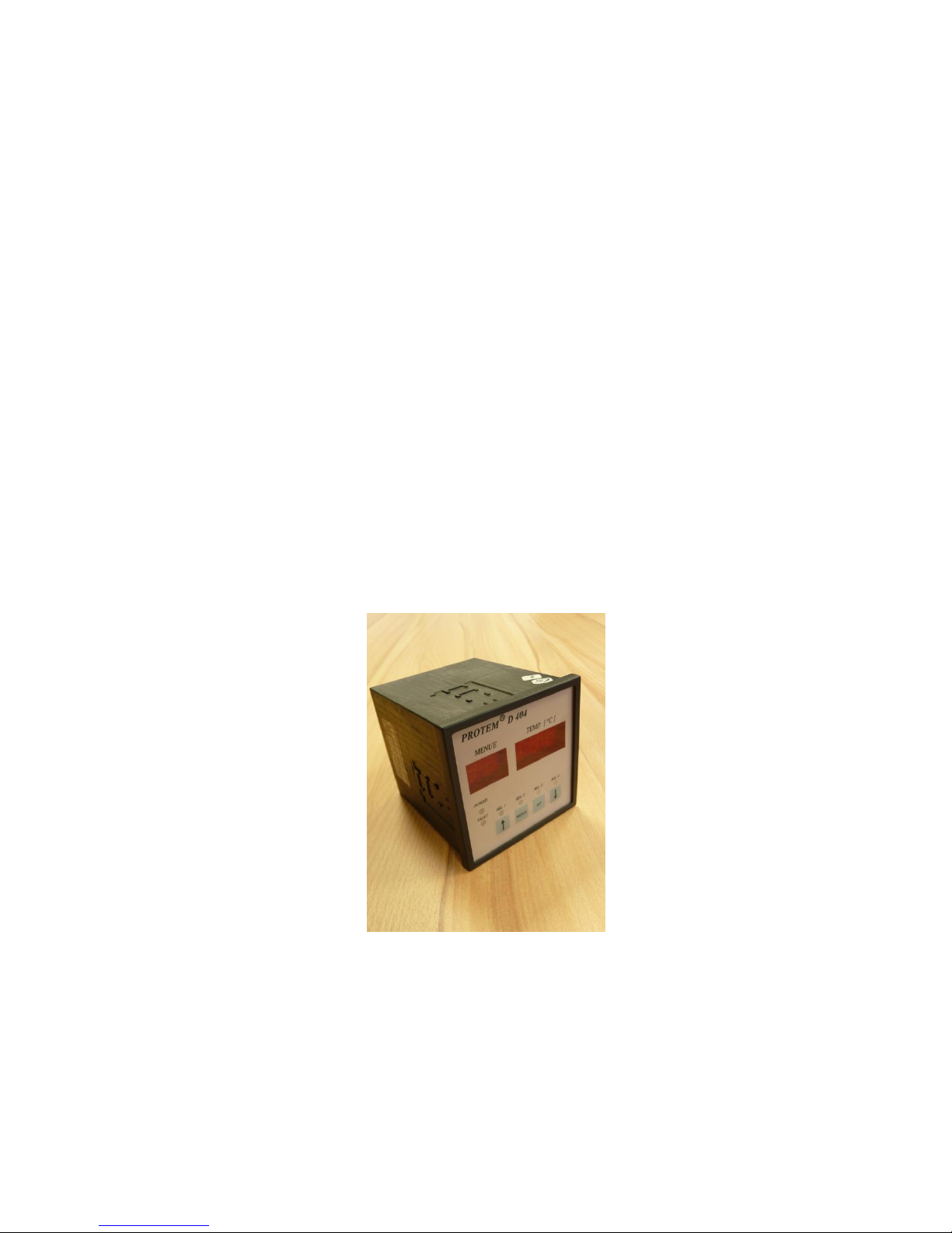
PROTEM
D 404
Version 2.6
Page 2

PROTEM® D 404 2
PROTEM D 404
Inhaltsverzeichnis
1.0 Sicherheitshinweise............................................................................................... 4
2.0 Technische Daten ................................................................................................. 5
3.0 Menüpunkte .......................................................................................................... 9
3.1 Wechsel zwischen den Menüpunkten ................................................................ 10
3.2 Aktuelle Temperatur ........................................................................................... 10
3.3 Maximale Temperatur ........................................................................................ 10
3.4 Eingabe von Daten ............................................................................................... 11
3.5 Eingabe der Zeitfunktionen ................................................................................ 11
4.0 DIP-Schalter S 501 .............................................................................................. 12
4.1 DIP-Schalter S 502 .............................................................................................. 14
5.0 Anschlussbelegungen ........................................................................................... 16
5.1 Anschlussbelegung Teststecker .......................................................................... 18
6.0 RS 232 Bedienung und Protokoll ....................................................................... 19
6.1 Allgemeines ......................................................................................................... 19
6.1.1 Terminalsoftware für DOS ................................................................................. 20
6.1.2 Terminalsoftware für Windows ......................................................................... 20
Page 3

PROTEM® D 404 3
PROTEM D 404
Table of Contents
1.0 Safety instructions ............................................................................................... 21
2.0 Technical data ..................................................................................................... 22
3.0 Menu items ........................................................................................................... 26
3.1 Change between the menu items ........................................................................ 27
3.2 Actual temperature ............................................................................................. 27
3.3 Maximum temperature ....................................................................................... 27
3.4 Input of data ......................................................................................................... 28
3.5 Input of time functions ........................................................................................ 28
4.0 DIP-Switch S 501 ................................................................................................. 29
4.1 DIP-Switch S 502 ................................................................................................. 31
5.0 Connections .......................................................................................................... 33
5.1 Connections table of the test plug ...................................................................... 35
6.0 RS 232 operation.................................................................................................. 36
6.1 General ................................................................................................................ 36
6.1.1 Software for DOS ................................................................................................ 37
6.1.2 Software for Windows ......................................................................................... 37
Page 4

PROTEM® D 404 4
1.0 Sicherheitshinweise
Vor der Inbetriebnahme der Temperaturüberwachungsgeräte PROTEM ist die vorliegende
Betriebsanleitung aufmerksam zu lesen. Sie enthält Informationen, die für einen störungsfreien
Betrieb unter Ausnutzung aller Vorteile des Gerätes notwendig sind.
Arbeiten am Gerät dürfen nur von autorisiertem Fachpersonal durchgeführt werden und
müssen unter Beachtung der einschlägigen Vorschriften des Elektrohandwerks erfolgen.
Mit diesen Sicherheitshinweisen wird kein Anspruch auf Vollständigkeit erhoben. Bei Fragen
und Problemen halten Sie bitte mit einem Techniker aus unserem Hause Rücksprache.
Die in diesem Gerätehandbuch dargestellten verfahrenstechnischen Hinweise und SchaltungsAusschnitte sind sinngemäß zu verstehen und auf Übertragbarkeit auf die jeweilige Anwendung
zu prüfen.
Die Angaben in diesem Gerätehandbuch beschreiben die Eigenschaften der Produkte, ohne diese
zuzusichern.
Page 5

PROTEM® D 404 5
2.0 Technische Daten
Spannungsversorgung 24... 250V AC/DC +/- 10% (DC ... 63 Hz)
Es muss keine Polarität berücksichtigt werden.
Überspannungskategorie III; Überspannungsspitzen bis 4.000 V
Leistungsbedarf ca. 10,5 VA
Vorsicherung für Gerät 1 A
Umgebungsbedingungen Verwendung in Innenräumen bis 2.000 m ü. NN
Umgebungstemperatur : - 20°C ... + 60°C
Verschmutzungsgrad : 2
Relative Luftfeuchte 5% - 85%, keine Betauung!
Lagertemperatur -25°C... +60°C
Transporttemperatur -25°C... +70°C
Schutzart IP20
Reinigung Die Gehäusefront kann mit einem mit Wasser
angefeuchteten Lappen gereinigt werden.
Messkreise 4 potentialfreie Messeingänge
Messfühler je Messkreis kann ein PT100 (Zweileiterausführung) oder
ein PT100 (Dreileiterausführung)eingesetzt werden.
Messbereich PT100 -28°C bis +200°C (-20 bis +190°C)
(Die Schaltpunkte des jeweiligen Relais sind innerhalb
dieses Bereiches frei wählbar)
Page 6

PROTEM® D 404 6
Relaisausgänge Pro Messkreis steht ein Relaisausgang zur Verfügung.
Jeder Relaisausgang ist mit einem potentialfreien Öffner
und einem potentialfreien Schließer versehen.
Die Ein-, Ausschaltpunkte sind für jedes Relais frei zu
programmieren.
Über die Software kann jedes Relais mittels einer
Zeitfunktion als abfall- oder anzugverzögertes Relais
programmiert werden.
Relaisdaten: Kontaktbelastung:
8 A 250 V AC (cos phi = 1,0)
3 A 250 V AC (cos phi = 0,4)
5 A 30 V DC (0 ms)
Lebensdauer: 107 Schaltspiele (mechanisch)
105 Schaltspiele (elektrisch)
ACHTUNG! Bei Betreiben eines Relaiskontaktes auf
berührungsgefährlichem Potential sind auch die anderen
Relaiskontakte als berührungsgefährlich anzusehen!
Sammelstörungsrelais Das Sammelstörungsrelais zeigt über einen potentialfreien
Schließerkontakt jede der nachfolgenden
Gerätestörungen
an.
1. Netzspannung fehlt
2. Temperaturfühler gebrochen
3. Programmierter Schaltpunkt vom Temperaturfühler
( PT100) erreicht
Zeitfunktionen Für die Relaisausgänge 1 bis 4 stehen zwei Zeitfunktionen
(Abfall-, Anzugsverzögerung) zur Verfügung.
Es kann für jeden Messeingang separat zwischen den Zeiten
0 ... 255 Sekunden und 10 ... 2550 Sekunden gewählt
werden.
Maximale Toleranz Zeitbereich 1 = 1 Sekunde
Maximale Toleranz Zeitbereich 2 = 10 Sekunden
Display Das Gerät ist mit einer 5-stelligen 7-Segment LED-Anzeige
ausgestattet.
LED Anzeigen 4 rote LED´s zeigen den Relaisstatus von Relais 1 bis 4 an.
Die gelbe LED zeigt eine Sammelstörung oder Netzausfall
an und die grüne LED zeigt Netzspannung OK an.
Max. Wert Speicher Ein EEPROM im Gerät speichert alle maximalen
Temperaturen nichtflüchtig ab.
Page 7

PROTEM® D 404 7
RS232 Interface Über ein eingebautes RS232 Interface können mit einem PC
oder einem Terminal Daten vom Gerät abgefragt werden.
Die Daten werden auf Anforderung gesendet (siehe Kapitel
6 für die Protokollbeschreibung).
Technische Daten der Schnittstelle:
Serielle Schnittstelle mit TXD-, RXD- und GNDAnschluss.
Übertragungsrate 9600 Baud, 8Bit, Non-Parity und 1
Stopbit (fest eingestellt).
Diese Funktion steht im Notstrombetrieb nicht zur
Verfügung!
20mA Ausgang Über einen Stromausgang ( 0 - 20 mA) können die 4
gemessenen Temperaturen und die 4 maximalen
Temperaturen angezeigt werden.
Technische Daten Ausgang:
Stromausgang 4 ... 20 mA
Toleranz maximal 0,5 mA vom Endwert
Diese Funktion steht im Notstrombetrieb nicht zur
Verfügung!
Teststecker Über einen Teststecker können Funktionen mittels eines
Testgerätes überprüft werden. Die Belegung des
Teststeckers ist in Kapitel 5.1 gezeigt.
Gehäuseabmessungen 96 mm x 96 mm x 120 mm (B x H x T)
Türausschnitt nach
DIN 43700 92
+0,8
mm x 92
+0,8
mm
Anschlussklemmen 2,5 mm² steckbar (Relaisausgänge und Spannungs-
versorgung) 1,5 mm² steckbar (Fühleranschlüsse)
Page 8

PROTEM® D 404 8
Achtung: EMV-Maßnahmen
Werden die Temperaturüberwachungsgeräte vom Typ PROTEM® in Anlagen eingesetzt, die
den EMV-Vorschriften entsprechen müssen, ist die Installation so vorzunehmen, dass die Anlage
den EMV-Richtlinien entspricht.
Hinweise zur EMV-gerechten Installation sind beim Hersteller erhältlich.
Page 9

PROTEM® D 404 9
3.0 Menüpunkte
Die Anzeige des Gerätes ist in zwei Spalten aufgeteilt. Auf der linken Seite befindet sich die
Menüspalte und auf der rechten Seite die Datenspalte. Die einzelnen Datenwerte sind in
nachfolgender Tabelle aufgelistet:
Änderung
Hersteller
Hersteller
Änderung
Datum
Programm
Menüpunkt
Daten
Programm
Datum
01
Aktuelle Temperatur an Fühler 1
02
Aktuelle Temperatur an Fühler 2
03
Aktuelle Temperatur an Fühler 3
04
Aktuelle Temperatur an Fühler 4
05
Maximaltemperatur an Fühler 1
06
Maximaltemperatur an Fühler 2
07
Maximaltemperatur an Fühler 3
08
Maximaltemperatur an Fühler 4
P 10
Anzugstemperatur aktives Relais Fühler 1
100° C
11
Abfalltemperatur aktives Relais Fühler 1
90° C T 12
Anzugstemperatur Sammelstörungsrelais Fühler 1*
150° C 13
Abfalltemperatur Sammelstörungsrelais Fühler 1*
145° C
100
14
Abfallverzögerungszeit aktives Relais Fühler 1
000 sek.
(Logik)
15
Anzugsverzögerungszeit aktives Relais Fühler 1
000 sek.
P
20
Anzugstemperatur aktives Relais Fühler 2
110° C 21
Abfalltemperatur aktives Relais Fühler 2
100° C T 22
Anzugstemperatur Sammelstörungsrelais Fühler 2 *
150° C 23
Abfalltemperatur Sammelstörungsrelais Fühler 2 *
145° C
100
24
Abfallverzögerungszeit aktives Relais Fühler 2
000 sek.
(Logik)
25
Anzugsverzögerungszeit aktives Relais Fühler 2
000 sek.
P
30
Anzugstemperatur aktives Relais Fühler 3
120° C 31
Abfalltemperatur aktives Relais Fühler 3
118° C T 32
Anzugstemperatur Sammelstörungsrelais Fühler 3 *
150° C 33
Abfalltemperatur Sammelstörungsrelais Fühler 3 *
145° C
100
34
Abfallverzögerungszeit aktives Relais Fühler 3
000 sek.
(Logik)
35
Anzugsverzögerungszeit aktives Relais Fühler 3
000 sek.
40
Anzugstemperatur aktives Relais Fühler 4
40° C P 41
Abfalltemperatur aktives Relais Fühler 4
35° C 42
Anzugstemperatur Sammelstörungsrelais Fühler 4 *
150° C T 43
Abfalltemperatur Sammelstörungsrelais Fühler 4 *
145° C
44
Abfallverzögerungszeit aktives Relais Fühler 4
000 sek.
100
45
Anzugsverzögerungszeit aktives Relais Fühler 4
000 sek.
* Anmerkung:
Die programmierten Schaltpunkte vom Menüpunkt 11 bzw. 21 bzw. 31 bzw. 41 müssen
mindestens 2°C unter denen vom Menüpunkt 10; 20, 30, 40 liegen.
Die programmierten Schaltpunkte vom Menüpunkt 13 bzw. 23 bzw. 33 bzw. 43 müssen
mindestens 2°C unter denen vom Menüpunkt 12, 22, 32, 42 liegen.
Page 10

PROTEM® D 404 10
3.1 Wechsel zwischen den Menüpunkten
Der Wechsel zu einem neuen Menüpunkt in der Anzeige erfolgt, indem zunächst die Taste
"Menü" betätigt wird . Ein Blinken der beiden Ziffern zeigt an, dass die Auswahl aktiv ist. Nun
kann mit den Tasten "Auf" bzw. "Ab" der Menüpunkt gewechselt werden (die Tasten sind mit
entsprechenden Pfeilen gekennzeichnet). Ist der Bediener am gewünschten Menüpunkt
angelangt, muss durch nochmaliges Betätigen der Taste "Menü" die Auswahl abgeschlossen
werden. Die Ziffern der Anzeige blinken nicht mehr und eine eventuelle Änderung der
angezeigten Daten kann jetzt vorgenommen werden.
3.2 Aktuelle Temperatur
Wenn einer der Menüpunkte für die jeweilige aktuelle Temperatur aktiviert wurde, erscheint in
der Datenanzeige folgende Meldung.
LED Display
- PT100 Fühler Temperatur in °C z.B. 125
- Kein Fühler Meldung no
Hinweis:
Die oben aufgelistete Anzeige "Kein Fühler" erscheint bei Aktivierung eines solchen Fühlers in
allen weiteren zugeordneten Menüpunkten des aktiven Fühlers.
Beispiel:
Wurde beim Fühlerkreis 1 die Funktion „Kein Fühler“ ausgewählt, erscheint die Meldung "no"
unter den Menüpunkten 01, 05, 10, 11, 12 und 13. Die Punkte 14 bis 15 zeigen weiterhin die
jeweilige Anzugs- oder Abfallzeit an. Dies gilt ebenso für alle anderen Fühlereingänge, jedoch
unter den jeweils zugeordneten Menünummern.
3.3 Maximale Temperatur
Die Menüpunkte 05 bis 08 sind die jeweiligen MaxWert-Speicher der einzelnen Fühler. Hier
wird der Spitzenwert der gemessenen Temperatur angezeigt. Der Wert wird im EEPROM
abgespeichert, so dass er unverlierbar ist und jederzeit abgefragt werden kann. Ein Rücksetzen
dieses Speichers erfolgt, indem der Menüpunkt aktiviert und anschließend die Taste "Set"
betätigt wird. Die Anzeige schaltet nun auf den momentan aktuellen Temperaturwert am
jeweiligen Fühler zurück.
Page 11

PROTEM® D 404 11
3.4 Eingabe von Daten
Ab Menüpunkt 10 aufwärts erlaubt das System eine Dateneingabe. Die Änderung der Daten
erfolgt, indem bei nichtblinkender Menünummer der jeweilige Wert mit den Tasten "Auf" und
"Ab" verändert wird. Dies geschieht entweder in Einer-Schritten bei einmaligem Betätigen der
jeweiligen Taste oder im Schnelldurchlauf bei Festhalten der jeweiligen Taste. Ein Blinken der
Datenanzeige zeigt an, dass der Vorgabewert verändert wurde und nun erst bestätigt werden
muss. Wenn der gewünschte Wert eingestellt ist, wird die Eingabe mit der Taste "Set"
abgeschlossen. Sollte eine Änderung vorgenommen worden sein, muss diese zwingend mit
"Set" bestätigt werden, da ansonsten kein anderer Menüpunkt mehr angewählt werden kann (bei
blinkender Anzeige muss immer eine Bestätigung erfolgen).
3.5 Eingabe der Zeitfunktionen
Bei der Eingabe von Zeitfunktionen ist darauf zu achten, dass bei Aktivierung einer
Anzugsverzögerungszeit die jeweilige Abfallverzögerungszeit auf Null gesetzt werden muss.
Dies gilt auch für den umgekehrten Fall.
Beispiel:
Wenn unter Menüpunkt 15 eine Zeit eingestellt wurde, muss die Zeit unter Menüpunkt 14 auf
Null gesetzt werden und umgekehrt.
Dies ist wichtig, da das System im Falle einer Doppelfunktion (Abfall- und Anzugsverzögerung)
immer die Abfallverzögerungszeit als aktive Zeitfunktion erkennt.
Die Einstellung der zwei verschiedenen Zeitbereiche (1... 255 Sekunden und 10 ... 2550
Sekunden) erfolgt, indem bei blinkender Anzeige und dem jeweils gültigen Menüpunkt für die
Zeitauswahl die Taste "Set" betätigt wird. Im LED Display leuchtet dann der Dezimalpunkt
hinter der Einer-Stelle der Zeitangabe auf. Die Umschaltung vom ersten Zeitbereich in den
zweiten Zeitbereich erfolgt jeweils für die einzelnen Fühler.
Beispiel:
Wenn für Fühler 1 der zweite Zeitbereich (10 ... 2550 Sekunden) unter Menüpunkt 14
ausgewählt wurde, so ist diese Zeit automatisch auch für den Menüpunkt 15 ausgewählt.
Page 12

PROTEM® D 404 12
4.0 DIP-Schalter S 501
Mit dem DIP Schalter S 501 kann folgende Funktion selektiert werden.
I
II
III
IV
Kanal
Kanal
1 2 3 4 5 6 7 8 Schalternummer
ON
ON x x x x x x
Fühler 1 = kein Fühler
ON
OFF x x x x x x
Fühler 1 = PT100 Einzelbetrieb
I
OFF
OFF x x x x x x
Fühler 1 = PT100 Logik
x x
ON
ON x x x x
Fühler 2 = kein Fühler
x x ON
OFF x x x x
Fühler 2 = PT100 Einzelbetrieb
II x x
OFF
OFF x x x x
Fühler 2 = PT100 Logik
x x x x
ON
ON x x
Fühler 3 = kein Fühler
x x x x
ON
OFF x x
Fühler 3 = PT100 Einzelbetrieb
III x x x x
OFF
OFF x x
Fühler 3 = PT100 Logik
x x x x x x
ON
ON
Fühler 4 = kein Fühler
x x x x x x
ON
OFF
Fühler 4 = PT100 Einzelbetrieb
IV
x x x x x x OFF
OFF
Fühler 4 = PT100 Logik
ON Schalter in ON Stellung
OFF Schalter in OFF Stellung
x Schalterstellung ohne Einfluss
Hinweis zur Funktion PT100 Logik:
Alle Fühlereingänge, die mit der Schalterstellung PT100 Logik erkannt werden, besitzen die
nachfolgend erklärte Funktion. Die jeweiligen Relais der einzelnen Kanäle sind mit einer
logischen Verknüpfung an die aktivierten Fühler versehen. Das heißt, wenn beispielsweise zwei
Kanäle in Stellung Logik stehen, dann gelten die eingestellten Schaltschwellen für beide
Eingänge. Für das Einschalten des jeweiligen Relais gilt, dass die Temperatur des PT100(1)
ODER PT100(2) größer ist als die eingestellte Temperatur. Für das Ausschalten des jeweiligen
Relais gilt, dass die Temperatur des PT100(1) UND PT100(2) kleiner ist als die eingestellte
Temperatur. Diese Verknüpfung kann mit allen vier Fühlern in beliebiger Kombination
vorgenommen werden.
Beispiel:
- Fühler 1 (PT100 Logik eingestellt)
Einschaltschwelle 30°C; Ausschaltschwelle 20°C;
- Fühler 2 (PT100 Logik eingestellt)
Einschaltschwelle 40°C; Ausschaltschwelle 30°C;
- Fühler 3 (PT100 Logik eingestellt)
Einschaltschwelle 50°C; Ausschaltschwelle 40°C;
Ablauf :
Die Temperatur steigt langsam am Fühler 1 auf 60°C;
- Temperatur >= 30°C Relais 1 schaltet EIN
- Temperatur >= 40°C Relais 2 schaltet EIN (Relais 1 ist weiter eingeschaltet)
- Temperatur >= 50°C Relais 3 schaltet EIN (Die beiden anderen bleiben eingeschaltet)
Page 13

PROTEM® D 404 13
Das gleiche gilt für die beiden anderen Kanäle.
Beim Ausschalten gilt die umgekehrte Reihenfolge. Allerdings muss hierbei die Temperatur an
allen Kanälen kleiner als die Abschaltschwelle sein, um das jeweilige Relais auszuschalten.
Hier gilt z.B. - Relais 3 = AUS = Fühler 1 UND Fühler 2 UND Fühler 3 40°C
Die Funktion der Schaltschwelle Sammelstörungsrelais ist wie beim PT100 Normalbetrieb
ausgelegt.
Beispiel:
Die Kombination der Fühler ist die gleiche geblieben, jedoch die Temperaturschwellen für das
Sammelstörungsrelais liegen für Fühler 1 bis 4 bei EIN 150°C und AUS 145°C.
Ablauf :
Temperatur an Fühler 1 steigt auf 150°C; die Temperatur an Fühler 2 und 3 liegt bei 45°C;
- Temperatur Fühler 1 = 130°C Relais 1, 2 und 3 sind EIN
- Temperatur Fühler 1 150°C Relais 2 und 3 sind EIN; Relais 1 schaltet AUS
Sammelstörungsrelais schaltet EIN
Hinweis!
Änderungen der DIP-Schalter-Einstellungen
am Schalter S 501 und S 502 werden erst beim
nächsten Einschalten wirksam. Zuvor muss die
Versorgungsspannung solange abgeschaltet werden,
bis die Kondensatoren entladen sind.
(Die grüne und die gelbe LED müssen erloschen sein!)
Page 14

PROTEM® D 404 14
4.1 DIP-Schalter S 502
Mit dem DIP Schalter S502 kann die jeweilige Eingangsbeschaltung (Vorwiderstände) jedes
Messeinganges selektiert werden (siehe nachfolgende Tabelle).
I
II
III
IV
Kanal
Kanal
1 2 3 4 5 6 7 8 Schalternummer
ON x x x x x x x Vorwiderstand, PT100 Fühler 1 "Ein"
OFF x x x x x x x Vorwiderstand, PT100 Fühler 1 "Aus"
I x ON x x x x x x
Parallelwiderstand PT 100 Fühler 1 "Ein"
x OFF x x x x x x
Parallelwiderstand PT 100 Fühler 1 "Aus"
x x ON x x x x x Vorwiderstand, PT100 Fühler 2 "Ein"
x x
OFF x x x x x Vorwiderstand, PT100 Fühler 2 "Aus"
II x x x ON x x x x
Parallelwiderstand PT 100 Fühler 2 "Ein"
x x x OFF x x x x
Parallelwiderstand PT 100 Fühler 2 "Aus"
x x x x
ON x x x Vorwiderstand, PT100 Fühler 3 "Ein"
x x x x
OFF x x x Vorwiderstand, PT100 Fühler 3 "Aus"
III x x x x x ON x x
Parallelwiderstand PT 100 Fühler 3 "Ein"
x x x x x
OFF x x
Parallelwiderstand PT 100 Fühler 3 "Aus"
x x x x x x
ON
x
Vorwiderstand, PT100 Fühler 4 "Ein"
x x x x x x
OFF
x
Vorwiderstand, PT100 Fühler 4 "Aus"
IV x x x x x x x ON
Parallelwiderstand PT 100 Fühler 4 "Ein"
x x x x x x x
OFF
Parallelwiderstand PT 100 Fühler 4 "Aus"
ON Schalter in ON Stellung
OFF Schalter in OFF Stellung
x Schalterstellung ohne Einfluss
Mit dem Schalter S 502 selektiert der Anwender zu dem jeweiligen Fühler die entsprechende
Eingangsbeschaltung (Hinzuschalten eines Vorwiderstandes im PT100 Betrieb). Im Falle einer
Parallelschaltung der Fühlereingänge mit dem angeschlossenem PT100 müssen bei den
parallelgeschalteten Eingängen diese Widerstände ausgeschaltet werden.
Beispiel:
An Fühler 1,2 und 3 soll ein PT 100 (Dreileiteranschluss), und an Fühler 4 kein Element
angeschlossen, sondern eine zweite Relaisfunktion für Fühler 1 belegt werden. In diesem Fall
müsste die Schalterstellung wie folgt aussehen:
- Fühler 1 PT100
Schalter 1 ON
Schalter 2 OFF
- Fühler 2 PT 100
Schalter 3 ON
Schalter 4 OFF
- Fühler 3 PT 100
Schalter 1 ON
Schalter 2 OFF
- Fühler 4 parallel an Fühler 1
(die Anschlüsse „2“ von Fühlereingang 1 und „11“ von Fühlereingang 4 werden gebrückt)
Schalter 1 OFF
Schalter 2 OFF
Page 15

PROTEM® D 404 15
Parallelschaltung der Fühlereingänge (Beispiel)
Zweite Relaisfunktion (Rel. 4) in
Abhängigkeit von Fühlereingang „1“
Zweite, dritte und vierte Relaisfunktion
(Rel. 2,3,4) in Abhängigkeit von Fühlereingang „1“
Zweite Relaisfunktion (Rel. 4) in
Abhängigkeit von Fühlereingang „1“
Zweite, dritte und vierte Relaisfunktion
(Rel. 2,3,4) in Abhängigkeit von Fühlereingang „1“
PT100 Dreileiterfühler
PT100 Zweileiterfühler
1 2 3 4 6 7 8 9 10
11
12
12
10 9 7
6 5 4 3 1
PT100 Dreileiterfühler
1 2 3 4 6 7 8 9 10
11
12
5
PT100 Zweileiterfühler
12
10 9 7 6 4 3 1
2 8 11
5
2 8 11
5
1 2 3 4 5 6 87
ON
OFF
S 502
1 2 3 4 5 6 87
ON
OFF
S 502
1 2 3 4 5 6 87
ON
OFF
S 502
1 2 3 4 5 6 87
ON
OFF
S 502
IV
III
II
I
Page 16

PROTEM® D 404 16
5.0 Anschlussbelegungen
Rückansicht Gerät:
1 2 3 4 5 6 7 8 9 10 11 12
13 14 15
21 22 23 24 25 26 27 28
31 32 33 34 35 36 37 38 39 40
1 2 3 4 5 6 7 8
S501
S502
Teststecker
Fühleranschlüsse
1 2 3 4 5 6 7 8
Relaiskontaktbelegung
Relais 1 Öffnerkontakt Klemme 31 und 32
Relais 1 Schließerkontakt Klemme 33 und 34
Relais 2 Öffnerkontakt Klemme 35 und 36
Relais 2 Schließerkontakt Klemme 37 und 38
Relais 3 Öffnerkontakt Klemme 21 und 22
Relais 3 Schließerkontakt Klemme 23 und 24
Relais 4 Öffnerkontakt Klemme 25 und 26
Relais 4 Schließerkontakt Klemme 27 und 28
Sammelstörungsrelais Schließerkontakt Klemme 39 und 40
Achtung!
Kontakt 39-40 schließt nach Anlegen der Versorgungsspannung und öffnet im
Fehlerfalle (Drahtbruch/Kurzschluss) oder bei fehlender Versorgungsspannung.
Versorgungsanschluss
Die Versorgungsspannung wird an die Klemmen 13 und 15 angeschlossen (die Polarität muss
nicht beachtet werden).
Page 17

PROTEM® D 404 17
Fühleranschlüsse
PT100 Dreileiterfühler
PT100 Zweileiterfühler
1 2 3 4 6 7 8 9 10
11
12
5
1 2 3 4 6 7 8 9 10
11
12
5
Page 18

PROTEM® D 404 18
5.1 Anschlussbelegung Teststecker
Die nachfolgende Aufstellung zeigt die Belegung der 25poligen D-Sub-Buchsenleiste.
Belegung Teststecker:
Pin 1 - nicht belegt
Pin 2 - TXD Anschluss RS 232 Interface
Pin 3 - RXD Anschluss RS 232 Interface
Pin 4 - nicht belegt
Pin 5 - nicht belegt
Pin 6 - nicht belegt
Pin 7 - GND RS232 Interface
Pin 8 - Anschluss 2 Fühler 1
Pin 9 - Anschluss 1 Fühler 2
Pin 10 - Anschluss 3 Fühler 2
Pin 11 - Anschluss 2 Fühler 3
Pin 12 - Anschluss 1 Fühler 4
Pin 13 - Anschluss 3 Fühler 4
Pin 14 - nicht belegt
Pin 15 - - Pol Stromausgang
Pin 16 - + Pol Stromausgang
Pin 17 - nicht belegt
Pin 18 - nicht belegt
Pin 19 - nicht belegt
Pin 20 - Anschluss 1 Fühler 1
Pin 21 - Anschluss 3 Fühler 1
Pin 22 - Anschluss 2 Fühler 2
Pin 23 - Anschluss 1 Fühler 3
Pin 24 - Anschluss 3 Fühler 3
Pin 25 - Anschluss 2 Fühler 4
Hinweis: Der Stromausgang ist nicht massebezogen und darf nur mit einem Shuntwiderstand
100 oder einem Drehspulmessgerät belastet werden ( I
max
= 20mA bei U
max
= 2V)!
Page 19

PROTEM® D 404 19
6.0 RS232 Bedienung und Protokoll
6.1 Allgemeines
Das Gerät ist für den Kommunikationsbetrieb über eine RS232 Schnittstelle ausgelegt. Der
Anschluss erfolgt mittels der beigestellten Datenleitung (die Pinbelegung ist in Zeichnung 6.1
dargestellt). Es können mit einem einfachen Protokoll Daten vom System abgefragt werden. Die
Datenübertragungsrate ist dem Kapitel "Technische Daten" zu entnehmen.
Die Datenabfrage kann mit jedem PC oder einem Standardterminal erfolgen. Bei Verwendung
eines PCs muss eine geeignete Terminalsoftware geladen werden z.B. das PROTEM® D404
Terminalprogramm für MS-DOS® ab Version 5.0 oder für Microsoft® WindowsTM ab Version 3.0.
Die PROTEM® D404 - Software ist menügeführt und auf 3,5“ Diskette erhältlich.
Abbildung 6.1 Schnittstellenleitung PROTEMPC
Das Protokoll zur Datenabfrage besteht aus 5 Befehlen, die nacheinander zum Gerät geschickt
werden müssen. Die Syntax der Befehle für DOS und Windows ist zwar gleich, durch die
unterschiedlichen Zeichensätze (ASCII und ANSI) unterscheidet sich jedoch die Schreibweise
der Befehle. Die Kommandos und die Gerätekennung sind in beiden Fällen gleich.
Kommando
Funktion
A
Aktuelle Temperatur Fühler 1
B
Aktuelle Temperatur Fühler 2
C
Aktuelle Temperatur Fühler 3
D
Aktuelle Temperatur Fühler 4
E
Maximale Temperatur Fühler 1
F
Maximale Temperatur Fühler 2
G
Maximale Temperatur Fühler 3
H
Maximale Temperatur Fühler 4
I
Relaisstatus Relais 1 bis 4
J
Automatischer Messprogrammdurchlauf
Nachdem die Befehle zum Gerät geschickt worden sind, erscheint unmittelbar im Klartext die
angeforderte Information auf dem Bildschirm.
Page 20

PROTEM® D 404 20
6.1.1 Benutzung der Terminalsoftware für DOS
1.Befehl ^B Start of Text (Taste STRG + B betätigen)
2.Befehl ^B Start of Text (Taste STRG + B betätigen)
3.Befehl Kommando (siehe Kommandos)
4.Befehl D Gerätekennung (möglich sind "A" bis "Z", hier als
Beispiel "D" gewählt)
5.Befehl CR oder ^M End of Text (Taste Return betätigen)
Beispiel:
Es wurde die "Aktuelle Temperatur Fühler 1" angefordert mit den Befehlen ^B ^B A D ^M.
Wenn z. B. die Temperatur 25°C beträgt, dann erscheint auf dem Bildschirm D025 als Antwort.
Die gewählte Gerätekennung (hier "D") wird immer zu Beginn der Antwort mitgeschickt, damit
man die Antwort eindeutig dem entsprechenden Gerät zuordnen kann.
6.1.2 Benutzung der Terminalsoftware für Windows
1.Befehl STX Start of Text (hexadezimal 02)
2.Befehl STX Start of Text
3.Befehl Kommando (siehe Kommandos)
4.Befehl D Gerätekennung (möglich sind "A" bis "Z", hier als
Beispiel "D" gewählt)
5.Befehl CR End of Text (hexadezimal 0D)
Beispiel:
Es wurde die "Aktuelle Temperatur Fühler 1" angefordert mit den Befehlen STX STX A D CR.
Wenn z. B. die Temperatur 25°C beträgt, dann erscheint auf dem Bildschirm D025 als Antwort.
Die gewählte Gerätekennung (hier "D") wird immer zu Beginn der Antwort mitgeschickt, damit
man die Antwort eindeutig dem entsprechenden Gerät zuordnen kann.
Microsoft und MS-DOS sind eingetragene Warenzeichen und Windows ist ein Warenzeichen der Microsoft Corporation in den vereinigten Staaten und anderen
Ländern.
Page 21

PROTEM® D 404 21
1.0 Safety instructions
Before commissioning temperature supervision module PROTEM it is important to read this
manual carefully. It is intended to give all information for an undisturbed operation together with
the exploitation of all advantages of the system. With regard to this product manual in hand
please consider that this is an English translation if the German original test. In case of doubt and
for legal reasons, the German original is valid in any case.
Only authorised specialists are allowed to work at the device in consideration of all
relevant regulations of the electrical industry. The guarantee given by us expires if the unit
is changed or (even partially) dismantled or if it is used in contradiction to our instructions.
These safety regulations are not entitled to completeness. In case of questions or problems please
contact our technicians.
The units, operational data and circuit details described in this manual have to be understood
analogously and have to be checked for transferability to each application.
The statements of this manual describe the product attributes without guaranteeing them.
Page 22

PROTEM® D 404 22
2.0 Technical data
Power supply 24... 250V AC/DC +/- 10% (DC ... 63 Hz)
There is no need to heed polarity.
Over voltage category III; voltage peaks up to 4.000 V
Power consumption approx. 10,5 VA
Serial fuse for unit 1 A
Ambient conditions operation up to 2.000 above sea level
ambient temperature range : - 20°C ... + 60°C
pollution factor : 2
Relative humidity 5% - 85%, not dewy!
Storing temperature -25°C... +60°C
Transport temperature -25°C... +70°C
Type of protection IP20
Cleaning The front panel can be cleaned with a moistened cloth.
Measuring circuits 4 potential free measuring inputs
Measuring sensors For each measuring circuit you can optionally use a PT100
(two wire type) or a PT100 (three wire type). The choice of
the respective measuring sensor can be done via DIP-switch
at the rear side of the device. Any combinations you like
between the four measuring circuits are possible.
Measuring range PT100 -28°C to +200°C (-20 to +190°C)
(The switching points of the respective relays are free
eligible within this measuring range)
Relay output For each measuring circuit there is one relay output
available. Every relay output is equipped with a potential
free break contact and a potential free make contact.
The switch on and switch-off points are free programmable
for each relay.
Via software you can programme each relay as a timer with
operate lag or with release lag.
Page 23

PROTEM® D 404 23
Relay characteristics Contact load:
8 A 250 V AC (cos phi = 1,0)
3 A 250 V AC (cos phi = 0,4)
5 A 30 V DC (0 ms)
Life : 107 switches (mechanical)
105 switches (electrical)
ATTENTION When operating one relay contact with a
touching-dangerous potential, also the other contacts must
be handled like touching-dangerous!
Collective error relay The collective error relay indicates each of the following
failures of the device by a potential free make contact:
1. missing of power supply
2. broken temperature sensor
3. programmed switch point of the temperature sensor
(PT100) has been reached.
Time functions For the outputs of relay 1-4 there are two time functions
(operate lag of release lag) available.
For each measuring input you can choose between the times
0 ... 255 seconds or 10 ... 2550 seconds separately.
Maximum tolerance of time range 1 : 1 second
Maximum tolerance of time range 2 : 10 seconds
Display The device is equipped with a 5-digit 7 segment display.
LED indication 4 red LED´s indicate the relay status from relay 1 to relay 4.
1 yellow LED indicates a collective error or a missing line
voltage.
1 green LED indicates line voltage is OK.
Max. value memory An EEPROM inside the device stores all maximum
temperatures.
RS232 Interface With the help of an installed RS 232 interface and by using
a PC You ca interrogate terminal data from the device. The
data will be sent on request. See chapter 6 for the protocol
description.
Technical data of the interface:
Serial bus with TXD-, RXD- and GND-connection.
Transmission rate 9600 Baud, 8 Bit, Non-Parity and
1 Stop Bit (fix).
This function isn’t available during standby generating!
Page 24

PROTEM® D 404 24
20mA output Via current output ( 0 - 20 mA) the 4 measured tempera-
tures and the 4 maximum temperatures can be indicated
Technical date of the output:
Current output 0 ... 20 mA
max. tolerance 0,5 mA of the final value
This function isn’t available during standby generating!
Test plug Function can be checked via a test plug. For a description of
the test plug see chapter 5.1.
Case dimensions Panel instrument 96 mm x 96 mm x 120 mm
Connecting terminals 2,5 mm² pluggable (power connection)
1,5 mm² pluggable (sensor connection)
Page 25

PROTEM® D 404 25
Attention: EMC-Measures
If the temperature supervision devices PROTEM® are used in plants, where the EMC-rules have
to be observed, the installation of the unit has to done in accordance with these rules.
Hints for a EMC-conform installation can be obtained from the manufacturer.
Page 26

PROTEM® D 404 26
3.0 Menu items
The display of the device is shared into two columns. The left column shows the menu field and
the right on shows the data filed. The individual data values are listed up in the following table:
1. Mod.
Producer
Producer
1. Mod.
Date
Program
Menu item
Data
Program
Date
01
Current temperature at sensor 1
02
Current temperature at sensor 2
03
Current temperature at sensor 3
04
Current temperature at sensor 4
05
Maximum temperature at sensor 1
06
Maximum temperature at sensor 2
07
Maximum temperature at sensor 3
08
Maximum temperature at sensor 4
P 10
Temperature to operate active relay sensor 1
100° C
11
Temperature to release active relay sensor 1
90° C T 12
Temperature to operate collective relay sensor 1 *
150° C 13
Temperature to release collective relay sensor 1 *
145° C
100
14
Release lag time relay sensor 1
000 sec.
(logic)
15
Operate lag time relay sensor 1
000 sec. P 20
Temperature to operate active relay sensor 2
110° C 21
Temperature to release active relay sensor 2
100° C T 22
Temperature to operate collective relay sensor 2 *
150° C 23
Temperature to release collective relay sensor 2 *
145° C
100
24
Release lag time relay sensor 2
000 sec.
(logic)
25
Operate lag time relay sensor 2
000 sec.
P 30
Temperature to operate active relay sensor 3
120° C 31
Temperature to release active relay sensor 3
118° C T 32
Temperature to operate collective relay sensor 3 *
150° C 33
Temperature to release collective relay sensor 3*
145° C
100
34
Release lag time relay sensor 3
000 sec.
(logic)
35
Operate lag time relay sensor 3
000 sec. 40
Temperature to operate active relay sensor 4
40° C P 41
Temperature to release active relay sensor 4
35° C 42
Temperature to operate collective relay sensor 4 *
150° C T 43
Temperature to release collective relay sensor 4 *
145° C
44
Release lag time relay sensor 4
000 sec.
100
45
Operate lag time relay sensor 4
000 sec.
* Remark:
The programmed switching points of menu item 11, 21, 31 respectively 41 must be at least 2°C
below the switching points 10, 20, 30, 40.
The programmed switching points of menu item 13, 23, 33 respectively 43 must be at least 2°C
below the switching points 12, 22, 32, 42.
Page 27

PROTEM® D 404 27
3.1 Change between menu items
For changing to a new menu item in the display you must push the button "Menu" first. Flashing
of the two menu numbers shows you that the choice is active. Now you can change the menu
item by using the keys "up" respectively "down" (the keys are marked with corresponding
arrows). If the desired menu item obtained the user has to complete the choice by pushing the
key "Menu" again. Now the menu numbers will stop flashing. A possible modification of the
indicated data can be made now.
3.2 Actual temperature
If one of the menu points for the respective actual temperature has been activated, a different
report according to the sensor type appears in the data display.
LED display
- PT100 sensor temperature in °C e.g. 125° C
- no sensor indicator no
Note!
The indication "no sensor" appears by activating such a sensor type in all further assigned menu
items of the active sensor.
For example:
If you have selected the function “no sensor” at sensor 1, the message ”no” appears in the
display for menu items 01, 05, 10, 11, 12 and 13. The items 14 to 15 still indicate the respective
operate lag time or the respective release lag time. This is also valid for all other sensor inputs,
but under the respective assigned menu numbers.
3.3 Maximum temperature
The menu item 05 to 08 are the respective maximum-value memories of the individual sensors.
At these menu items the peak value of the measured temperature will be indicated. The value
will be stored in the EEPROM so that it can't get lost and you can always poll this value. A reset
of the memory can be done by activating the menu item and pushing the button "Set". Then the
display switches to the actual temperature value of the respective sensor.
Page 28

PROTEM® D 404 28
3.4 Input of data
From menu item 10 upwards the system allows data input. The change of data follows by
pushing the "up" and "down" keys during the menu numbers are not flashing. This can be done
either step-by-step (by pushing the key once) or by the high-speed search (while keeping the key
pushed). A plashing of the display indicates that the given value has been modified. The input
must be completed by pushing the key "Set". Otherwise you are not able to change to an other
menu item. Every time when the display is flashing you must first push the "Set" key before you
can change to an other menu item.
3.5 Input of time functions
At the input of time functions you have to pay attention to the following:
You have to note that you must set the release lag time to zero by activating an operate lag time.
This is also valid for the reverse case.
Example :
If a time value is adjusted in menu item 15 the time in menu item 14 must be set to zero (proceed
analogous for the reverse case).
This is very important, because in case of a double-function (operate lag and release lag
together) the system always recognises the release lag as it's active time function.
The adjustment of the two different time ranges (1... 255 seconds and 10 ... 2550 seconds) can be
happen by pushing the "Set" key during the display is flashing and the menu item for time choice
is active. At the LED display the decimal dot is shining at the first place of the time display. A
switch from the short time interval to the long time interval happens for the respective sensors.
Example:
If the long time interval has been selected for sensor 1 within menu item 14, then it is also
relevant for the sensor 1 within menu item 15.
Page 29

PROTEM® D 404 29
4.0 DIP-Switch S 501
By the DIP switch S 501 you can select the respective type of sensor (refer to following table).
I
II
III
IV
channel
Channel
1 2 3 4 5 6 7 8 Switch number
ON
ON x x x x x x
Sensor 1 = no Sensor
ON
OFF x x x x x x
Sensor 1 = PT100 single operation
I
OFF
OFF x x x x x x
Sensor 1 = PT100 Logic
x x
ON
ON x x x x
Sensor 2 = no Sensor
x x
ON
OFF x x x x
Sensor 2 = PT100 single operation
II x x
OFF
OFF x x x x
Sensor 2 = PT100 Logic
x x x x ON
ON x x
Sensor 3 = no Sensor
x x x x ON
OFF x x
Sensor 3 = PT100single operation
III
x x x x OFF
OFF x x
Sensor 3 = PT100 Logic
x x x x x x
ON
ON
Sensor 4 = no Sensor
x x x x x x
ON
OFF
Sensor 4 = PT100 single operation
IV
x x x x x x OFF
OFF
Sensor 4 = PT100 Logic
ON switch in ON position
OFF switch in OFF position
x switch position without effect
Information about the PT100 logic function:
All sensor inputs, which are recognised by the switch position PT100 logic, have the in the
following described function. The relays of the respective channels are equipped with a logical
combination with the active sensor. So if for two channels the logical function is active, the
adjusted thresholds are valid for both channels. The relay switches on, if the temperature of
PT100(1) OR PT100(2) is higher than the adjusted temperature. It switches off, if the
temperatures of PT100(1) AND PT100(2) are lower than the adjusted temperature. This logical
operation can be done with all of the four sensors in any combination.
Page 30

PROTEM® D 404 30
Example 1:
- Sensor 1 (PT100 logic active)
Switch on threshold 30°C; switch off threshold 20°C;
- Sensor 1 (PT100 logic active)
Switch on threshold 40°C; switch off threshold 30°C;
- Sensor 1 (PT100 logic active)
Switch on threshold 50°C; switch off threshold 40°C;
Sequence:
The temperature rises slowly at sensor 1 to 60°C;
- temperature >= 30°C Relay 1 switches ON
- temperature >= 40°C Relay 2 switches ON (Relay 1 stays ON)
- temperature >= 50°C Relay 3 switches ON (both other relays stay ON)
The same is valid for the other two channels.
When switching off, the order is inverted, if the temperature in all channels is lower than the
switch off threshold for the respective relay.
E.g.: - Relay 3 = OFF = sensor 1 AND sensor 2 AND sensor 3 40°C
The function of the threshold of the collective error relay the same as standard operation with the
PT 100.
Example 2:
The combination of the sensors is the same , but the temperature thresholds for the collective
error relay now are set to ON 150°C and OFF 145°C for sensor 1 to 4.
Sequence:
The temperature at sensor 1 rises to 150°C; the temperature at the sensor 2 and 3 is constant at
45°C;
- temperature sensor 1 = 130°C Relay 1, 2 and 3 are ON
- temperature sensor 1 150°C Relay 2 and 3 are ON; Relay 1 switches OFF
collective error relay switches OFF
Changes of the DIP-switches S501 and S502 take
only effect when the supply voltage was switched off
and the capacitors were discharged.
(Green and yellow LED must be extinct!)
Page 31

PROTEM® D 404 31
4.1 DIP-Switch S 502
By the DIP switch S502 you can select the respective input circuit (series or parallel resistors) of
each measuring input (refer to the following table).
I
II
III
IV
channel
Channel
1 2 3 4 5 6 7 8 switch number
ON X x x x x x x series resistor, PT100 sensor 1 "On"
OFF X x x x x x x series resistor, PT100 sensor 1 "Off"
I x ON x x x x x x
parallel resistor PT 100 sensor 1 "On"
x OFF x x x x x x
parallel resistor PT 100 sensor 1 "Off"
x X ON x x x x x series resistor, PT100 sensor 2 "On"
x X
OFF x x x x x series resistor, PT100 sensor 2 "Off"
II x X x ON x x x x
parallel resistor PT 100 sensor 2 "On"
x X x OFF x x x x
parallel resistor PT 100 sensor 2 "Off"
x X x x
ON x x x series resistor, PT100 sensor 3 "On"
x X x x
OFF x x x series resistor, PT100 sensor 3 "Off"
III x X x x x ON x x
parallel resistor PT 100 sensor 3 "On"
x X x x x
OFF x x
parallel resistor PT 100 sensor 3 "Off"
x X x x x x
ON
x
series resistor, PT100 sensor 4 "On"
x X x x x x
OFF
x
series resistor, PT100 sensor 4 "Off"
IV x x x x x x x ON
parallel resistor PT 100 sensor 4 "On"
x x x x x x x
OFF
parallel resistor PT 100 sensor 4 "Off"
ON switch in ON position
OFF switch in OFF position
x switch position without effect
With the switch S 502 the user selects the corresponding input circuit for the respective sensor
(e.g.: adding a series resistor in PT100 operation). If several sensor inputs are connected in
parallel with one PT 100, at these inputs the resistors have to be switched off.
Example:
At sensor 1,2 and 3 a PT 100 (three wire type) and at sensor 4 no sensor, but a second relay
function for sensor 1 are connected. In this case the switch mode has to be like follows:
- Sensor 1 PT100
Switch 1 ON
Switch 2 OFF
- Sensor 2 PT 100
Switch 3 ON
Switch 4 OFF
- Sensor 3 PT 100
Switch 1 ON
Switch 2 OFF
- Sensor 4 parallel to sensor 1
(the terminals „2“ of sensor input 1 and „11“ of sensor input 4 have to be bridged)
Switch 1 OFF
Switch 2 OFF
Page 32

PROTEM® D 404 32
Parallel connection of the sensor inputs (example)
Second relais function (rel. 4)
in addiction to sensor input „1“
Second, third and fourth relais function
(rel. 2,3,4) in addiction to sensor input „1“
Second relais function (rel. 4)
in addiction to sensor input „1“
Second, third and fourth relais function
(rel. 2,3,4) in addiction to sensor input „1“
PT100 2-wire sensor
PT100 2-wire sensor
1 2 3 4 6 7 8 9 10
11
12
12
10 9 7 6 5 4 3 1 PT100 3-wire sensor
1 2 3 4 6 7 8 9 10
11
12
5
PT100 2-wire sensor
12
10 9 7 6 4 3 1
2 8 11
5
2 8 11
5
I
II
III
IV
1 2 3 4 5 6 87
ON
OFF
S 502
1 2 3 4 5 6 87
ON
OFF
S 502
1 2 3 4 5 6 87
ON
OFF
S 502
1 2 3 4 5 6 87
ON
OFF
S 502
Page 33

PROTEM® D 404 33
5.0 Connections
Rear view of the device:
1 2 3 4 5 6 7 8 9 10 11 12
13 14 15
21 22 23 24 25 26 27 28
31 32 33 34 35 36 37 38 39 40
1 2 3 4 5 6 7
8
S501
S502
Sensor connection
1 2 3 4 5 6 7
8
Power Supply
Relay contact occupation
Relay 1 break contact Terminal 31 und 32
Relay 1 make contact Terminal 33 und 34
Relay 2 break contact Terminal 35 und 36
Relay 2 make contact Terminal 37 und 38
Relay 3 break contact Terminal 21 und 22
Relay 3 make contact Terminal 23 und 24
Relay 4 break contact Terminal 25 und 26
Relay 4 make contact Terminal 27 und 28
Collective Error relay make contact Terminal 39 und 40
Attention!
The contact 39-40 is closed after connecting the power supply under normal
conditions and will be opened when:
1. missing power supply
2. broken wire or short circuit in the measuring circuit
3. programmed switch-point reached (exceeded temperature)
Power supply
The power supply has to be connected to the terminals 13 and 15 without heeding the
polarity.
Page 34

PROTEM® D 404 34
Sensor connection
PT100 3-wire sensor
PT100 2-wire sensor
1 2 3 4 6 7 8 9 10
11
12
5
1 2 3 4 6 7 8 9 10
11
12
5
Page 35

PROTEM® D 404 35
5.1 Terminal occupation of the test plug
The following list shows the connection of the 25-Sub-D connector of the test plug.
Test plug:
Pin 1 - not connected
Pin 2 - TXD RS 232 Interface
Pin 3 - RXD RS 232 Interface
Pin 4 - not connected
Pin 5 - not connected
Pin 6 - not connected
Pin 7 - GND RS232 Interface
Pin 8 - Connection 2 Sensor 1
Pin 9 - Connection 1 Sensor 2
Pin 10 - Connection 3 Sensor 2
Pin 11 - Connection 2 Sensor 3
Pin 12 - Connection 1 Sensor 4
Pin 13 - Connection 3 Sensor 4
Pin 14 - not connected
Pin 15 - minus pole current output
Pin 16 - plus pole current output
Pin 17 - not connected
Pin 18 - not connected
Pin 19 - not connected
Pin 20 - Connection 1 Sensor 1
Pin 21 - Connection 3 Sensor 1
Pin 22 - Connection 2 Sensor 2
Pin 23 - Connection 1 Sensor 3
Pin 24 - Connection 3 Sensor 3
Pin 25 - Connection 2 Sensor 4
Remark: the current output is not related to ground and it is only allowed to use it with a shunt
resistor 100 or with a magnet moving coil instrument ( I
max
= 20mA at U
max
= 2V)!
Page 36

PROTEM® D 404 36
6.0 RS232 operation and protocol
6.1 General
The device is designed for communication via the RS232 interface. The connection can be done
by the added cables (the terminal occupation is shown in figure 6.1). With a simple record you
can read the data from the system. The data-transfer rate is shown in chapter1 (technical data).
The data interrogation can happen an any kind of PC or standard terminal. By using a PC, you
must have a software like a terminal program of DOS 5.0 or higher or you can use Microsoft
Windows 3.0 or 3.1. The PROTEM D404 Software is available on a 3,5’’ disk and is guided via
menu.
Figure 6.1 interface cable PROTEMPC
The record for interrogate the data includes 5 instructions, which must be send to the device
serially. The syntax of the instructions for DOS and Windows are the same, but caused by the
different character sets (ASCII and ANSI) the spelling is different. The command and the device
identification are the same in both matters.
Command
Function
A
Actual temperature sensor 1
B
Actual temperature Sensor 2
C
Actual temperature Sensor 3
D
Actual temperature Sensor 4
E
Maximum temperature Sensor 1
F
Maximum temperature Sensor 2
G
Maximum temperature Sensor 3
H
Maximum temperature Sensor 4
I
Relay status relay 1 to 4
J
Auto run measure program
After sending the commands the return-message is readable on the screen.
Page 37

PROTEM® D 404 37
6.1.1 Use of the terminal software for DOS
1.instruction ^B Start of Text (Push key Control + B)
2.instruction ^B Start of Text (Push key Control + B)
3.instruction command (see commands)
4.instruction D Device identification ( "A" to "Z" are possible,
"D" has been chosen here)
5.instruction CR or ^M End of Text (Push Return Key)
Example:
The command for the actual temperature ^B^BAD^M has been send. As answer on the screen
you can see the letters D0 25 if the temperature is 25°C. The code D at the beginning of the
answer is send every time to distinguish between the different devices.
6.1.2 Use of the terminal software for Windows
1.instruction STX Start of Text (hexadecimal 02)
2.instruction STX Start of Text
3.instruction command (see commands)
4.instruction D Device identification ( "A" to "Z" are possible,
"D" has been chosen here)
5.instruction CR End of Text (hexadecimal 0D)
Example:
The command for the actual temperature STX STX A D CR has been send. As answer on the
screen you can see the letters D0 25 if the temperature is 25°C. The code D at the beginning of
the answer is send every time to distinguish between the different devices.
Page 38

PROTEM® D 404 38
_________________________________________________________
ELTROPLAN ELEKTROTECHNISCHE ANLAGEN GMBH
Edisonstr. 3, 59199 Bönen, Tel.: 02383/92022-0, Fax: 02383/92022-67
________________________________________________________________________________________
 Loading...