

Page 1
ELTRONIKA sp. z.o.o.
Ul. Warszawska 41 lok.7
05-092 Łomianki
[email protected]
www.eltronika.com
- Polska: +48 22 751 97 44
- Česká republika: +420 228 880 487
- Slovensko: +421 904 540 707
1
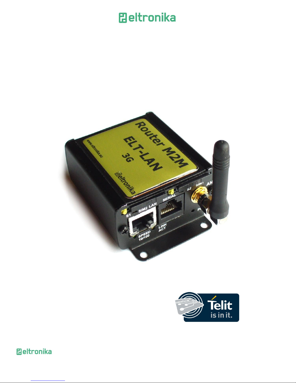
ELT-LAN
Preliminary User Manual
Date: 3-Nov-15
Page 2

ELTRONIKA sp. z.o.o.
Ul. Warszawska 41 lok.7
05-092 Łomianki
[email protected]
www.eltronika.com
- Polska: +48 22 751 97 44
- Česká republika: +420 228 880 487
- Slovensko: +421 904 540 707
2
1 Contents
ELT-LAN .................................................................................................................................... 1
Preliminary User Manual ...................................................................................................... 1
1 Contents .............................................................................................................................. 2
2 Overview ............................................................................................................................. 5
3 Trademarks ......................................................................................................................... 5
4 Package ............................................................................................................................... 6
4.1 Box ............................................................................................................................... 6
4.2 Complete package contents ........................................................................................ 7
4.3 Modem version ............................................................................................................ 8
5 General presentation .......................................................................................................... 9
5.1 Front panel .................................................................................................................. 9
5.2 Back panel .................................................................................................................... 9
5.3 External connections ................................................................................................. 10
5.3.1 Interfaces and connectors .................................................................................. 10
5.3.1.1 GSM antenna connector ............................................................................. 10
5.3.1.2 Modem serial port, either full RS232/RS485 .............................................. 10
5.3.1.3 RJ-45 connector .......................................................................................... 10
5.3.1.4 Power supply connector ............................................................................. 11
5.3.1.5 Audio I/O ..................................................................................................... 11
5.3.1.6 20-pin connector ......................................................................................... 12
5.3.2 SIM card holders................................................................................................. 13
5.4 Product sticker ........................................................................................................... 13
6 Basic features and services ............................................................................................... 14
7 Using the modem .............................................................................................................. 15
7.1 Setting up the modem ............................................................................................... 15
7.1.1 Inserting SIM card(s) .......................................................................................... 15
7.1.2 Connecting antenna ........................................................................................... 16
7.1.3 Connecting power supply cable ......................................................................... 17
7.1.4 Connecting UTP cable with RJ-45 ....................................................................... 17
7.2 Modem configuration ................................................................................................ 18
Page 3

ELTRONIKA sp. z.o.o.
Ul. Warszawska 41 lok.7
05-092 Łomianki
[email protected]
www.eltronika.com
- Polska: +48 22 751 97 44
- Česká republika: +420 228 880 487
- Slovensko: +421 904 540 707
3
7.2.1 Setting up the connection .................................................................................. 18
7.2.2 Modem status page............................................................................................ 18
7.2.3 Local network ..................................................................................................... 20
7.2.4 GSM network / WiFi network ............................................................................ 21
7.2.5 Connection control ............................................................................................. 23
7.2.6 Ports configuration ............................................................................................. 24
7.2.7 TCP/IP forwarding .............................................................................................. 25
7.2.8 VLAN ................................................................................................................... 26
7.2.9 Static routes ....................................................................................................... 26
7.2.10 Dynamic DNS ...................................................................................................... 27
7.2.11 Access control .................................................................................................... 28
7.2.12 Open VPN ........................................................................................................... 30
7.2.13 Ipsec static/Ipsec mobile .................................................................................... 31
7.2.14 Generating SSL certificates ................................................................................. 35
7.2.15 N2N ..................................................................................................................... 37
7.2.16 CARP ................................................................................................................... 37
7.2.17 NTRIP configuration page ................................................................................... 38
7.2.18 SMS Actions ........................................................................................................ 39
7.2.19 GPIO .................................................................................................................... 40
7.2.20 CAN ..................................................................................................................... 43
7.2.21 Time .................................................................................................................... 43
7.2.22 Syslog .................................................................................................................. 44
7.2.23 User files ............................................................................................................. 45
7.2.24 Backup and restore ............................................................................................ 46
7.2.25 Discard changes .................................................................................................. 47
7.2.26 Save settings ....................................................................................................... 47
7.3 System logs description ............................................................................................. 47
7.4 Firmware update ....................................................................................................... 49
7.5 Eltronika Device Manager ......................................................................................... 50
8 Troubleshooting ................................................................................................................ 52
8.1 No communication with the modem ........................................................................ 52
Page 4

ELTRONIKA sp. z.o.o.
Ul. Warszawska 41 lok.7
05-092 Łomianki
[email protected]
www.eltronika.com
- Polska: +48 22 751 97 44
- Česká republika: +420 228 880 487
- Slovensko: +421 904 540 707
4
8.2 Modem answers but there is no internet connection .............................................. 52
9 Technical characteristics ................................................................................................... 53
9.1 Mechanical characteristic .......................................................................................... 53
9.2 Housing (dimension diagram) ................................................................................... 53
9.3 Electrical characteristic .............................................................................................. 54
9.3.1 Power supply ...................................................................................................... 54
9.3.2 RF characteristics................................................................................................ 54
9.3.2.1 Frequency ranges ........................................................................................ 54
9.3.2.2 WiFi characteristics : ................................................................................... 56
9.3.2.3 External antenna ......................................................................................... 56
9.4 Environmental characteristic ..................................................................................... 56
10 Terminal architecture .................................................................................................... 57
11 Safety recommendations .............................................................................................. 58
11.1 General Safety ........................................................................................................... 58
11.2 Care and Maintenance .............................................................................................. 59
11.3 Responsibility ............................................................................................................. 59
12 Accessories .................................................................................................................... 60
12.1 Accessories critical for using modem ........................................................................ 60
12.2 Additional accessories ............................................................................................... 60
12.2.1 Directional antennas .......................................................................................... 60
12.2.2 Omnidirectional antennas .................................................................................. 62
13 On-line support ............................................................................................................. 63
14 Certifications ................................................................................................................. 66
14.1 Conformity Assessment Issues .................................................................................. 66
14.2 Declatarions of conformity ........................................................................................ 66
14.3 National restrictions .................................................................................................. 68
15 List of Acronyms ............................................................................................................ 69
Page 5

ELTRONIKA sp. z.o.o.
Ul. Warszawska 41 lok.7
05-092 Łomianki
[email protected]
www.eltronika.com
- Polska: +48 22 751 97 44
- Česká republika: +420 228 880 487
- Slovensko: +421 904 540 707
5
2 Overview
This document contains full ELT-LAN modem description and gives information
about installation and using it.
ELT-LAN terminal is a small terminal-modem powered by Telit. This modem
supports GSM/GPRS/EDGE/UMTS/HSPA/LTE and is dedicated for users seeking for
easy and mobile Internet access. Internet connection is easily available and configurable
via internet browser without any need of installing software or drivers for the device.
3 Trademarks
TELIT and the Stylized T Logo are registered in Trademark Office. All other product or
service names are the property of their respective owners.
Copyright © Telit Communications S.p.A. 2011.
Page 6
ELTRONIKA sp. z.o.o.
Ul. Warszawska 41 lok.7
05-092 Łomianki
[email protected]
www.eltronika.com
- Polska: +48 22 751 97 44
- Česká republika: +420 228 880 487
- Slovensko: +421 904 540 707
6
4 Package
4.1 Box
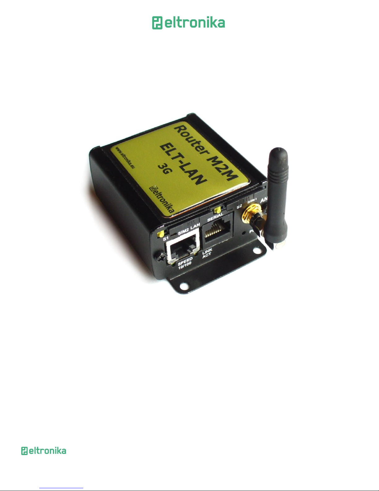
Original box contains below product .
We can find product sticker on the box. It matches modems sticker that is placed
on the device. This proves that your modem is original product. More information about
stickers in chapter 5.4 Product sticker.
Page 7
ELTRONIKA sp. z.o.o.
Ul. Warszawska 41 lok.7
05-092 Łomianki
[email protected]
www.eltronika.com
- Polska: +48 22 751 97 44
- Česká republika: +420 228 880 487
- Slovensko: +421 904 540 707
7
4.2 Complete package contents
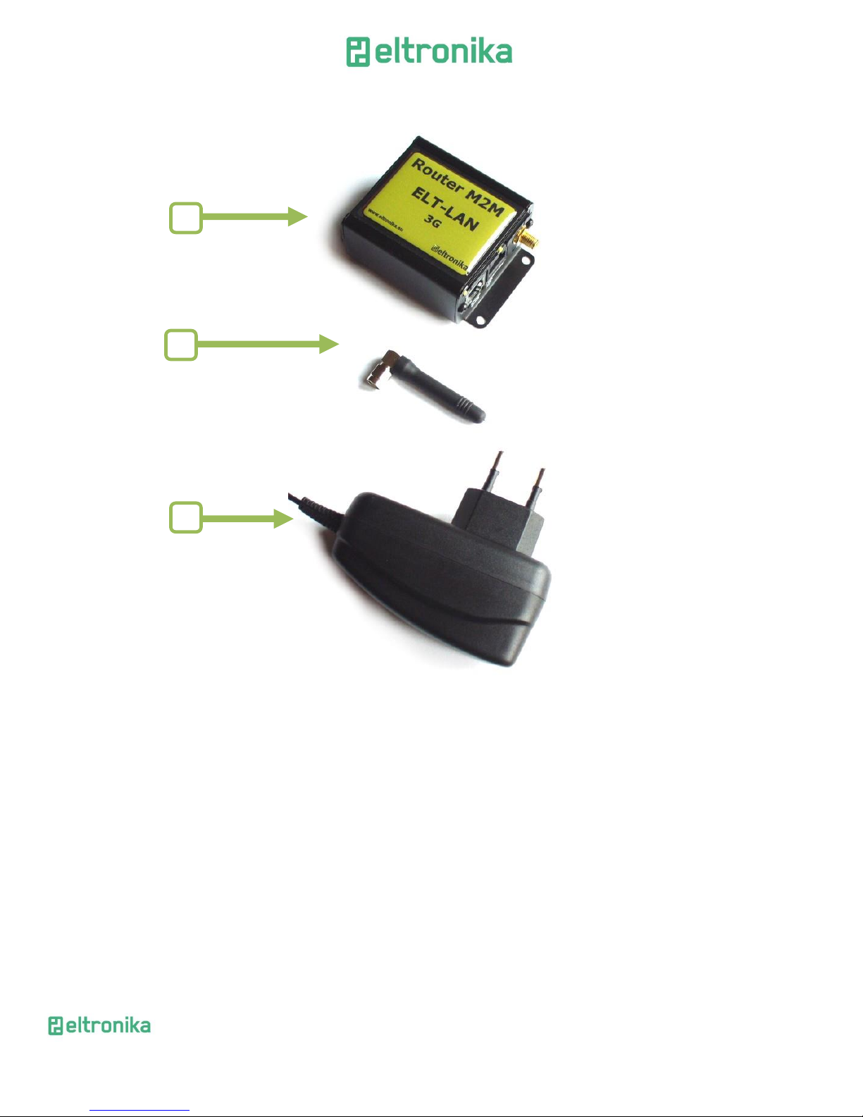
Complete package contains:
A. ELT-LAN modem
B. Antenna GSM (via SMA)
C. Power supply adapter
A
B
C
Page 8
ELTRONIKA sp. z.o.o.
Ul. Warszawska 41 lok.7
05-092 Łomianki
[email protected]
www.eltronika.com
- Polska: +48 22 751 97 44
- Česká republika: +420 228 880 487
- Slovensko: +421 904 540 707
8
4.3 Modem version
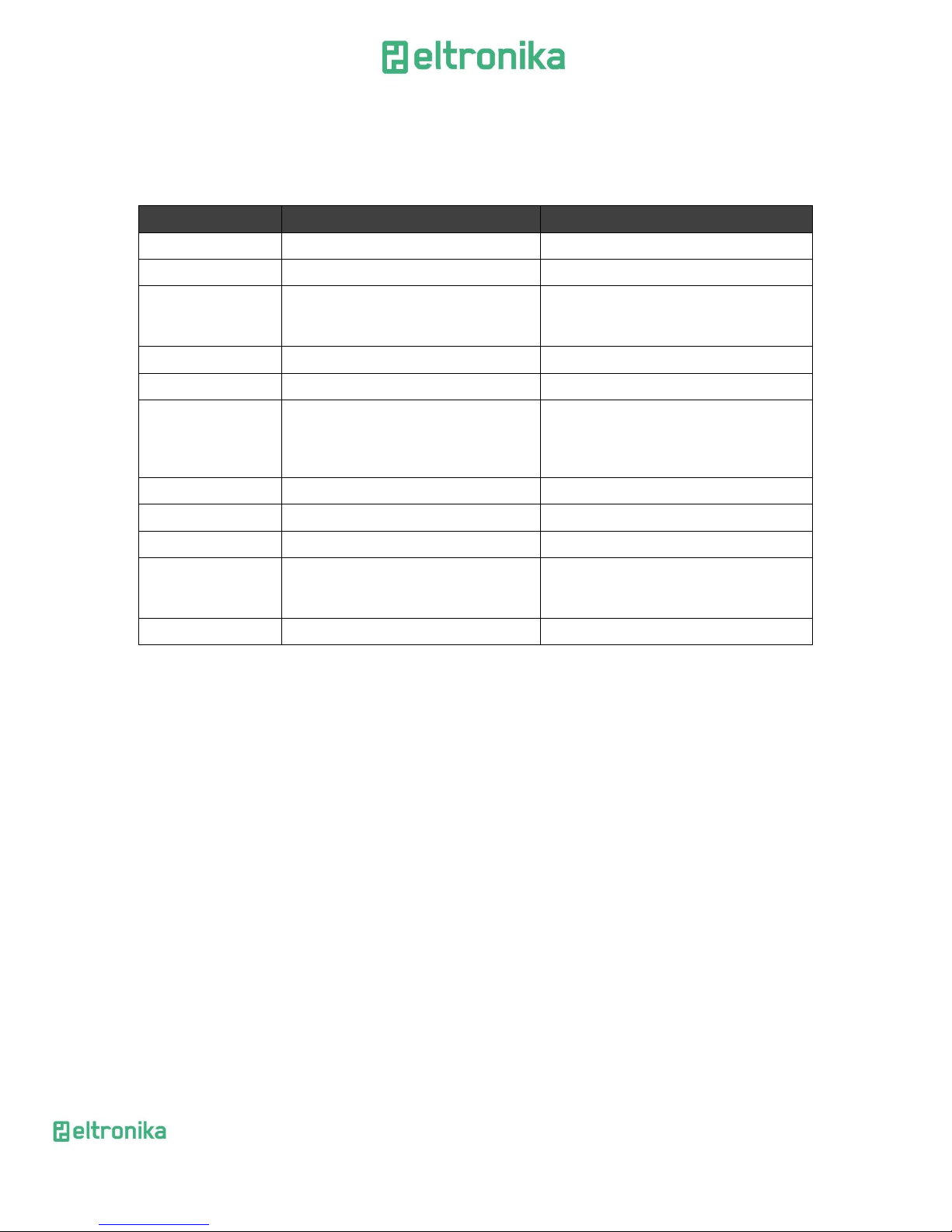
There are many ways to upgrade your ELT-LAN modem. List below shows typical
configuration and different combinations (versions) of this terminal.
Option
Typical
Option
Power supply
6-30V
-
CPU
IMX286 450MHz
IMX286 450MHz
Memory
128MB RAM, 512MB MicroSD card
(part used for Linux system, the size of
SD card can be changed in the future)
-
RS232
Systems console
Second RS485, instead of RS232
RS485
1
2
I/O connectors
-
4 digital inputs, 4 digital outputs, ADC
output, 2 analog inputs, I2C, CAN
interface, 3.3V output power supply,
audio I/O, miniUSB 2.0
Connection
HSPA+ (GSM, GPRS, EDGE)
UMTS, LTE
SIM
Extractable
Built-in
Dual SIM - Option unavailable
Audio codec
-
Mono microphone. Stereo input LINE IN,
Stereo output LINE OUT, or Speaker
output SPK OUT
LAN
Ethernet 10/100Mbps
WiFi modem
Modem port configuration depends on central module used.
Page 9
ELTRONIKA sp. z.o.o.
Ul. Warszawska 41 lok.7
05-092 Łomianki
[email protected]
www.eltronika.com
- Polska: +48 22 751 97 44
- Česká republika: +420 228 880 487
- Slovensko: +421 904 540 707
9
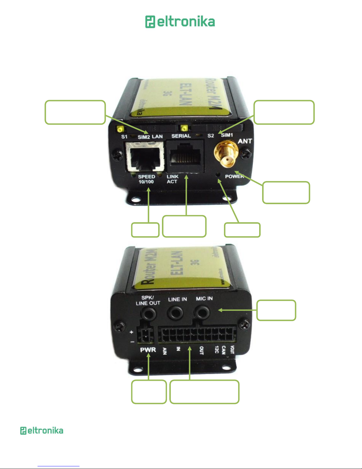
5 General presentation
5.1 Front panel
5.2 Back panel
Power
supply
SMA antenna
connector
RJ-45 (RS232
or RS485)
RJ-45
MASTER SIM card
holder
Power LED
Optional 20-pin
connector*
Audio I/O
lines*
*available as option
SLAVE SIM card
holder*
Page 10
ELTRONIKA sp. z.o.o.
Ul. Warszawska 41 lok.7
05-092 Łomianki
[email protected]
www.eltronika.com
- Polska: +48 22 751 97 44
- Česká republika: +420 228 880 487
- Slovensko: +421 904 540 707
10
5.3 External connections
5.3.1 Interfaces and connectors
5.3.1.1 GSM antenna connector
SMA antenna connector placed on front panel is used to connect external GSM. To
establish connection with GSM network an external antenna must be used. Type of
antenna depends on GSM coverage. In good circumstances (level of received signal is
high) use antenna which is attached in the package. If range of GSM is low or none, an
outdoor directional/omnidirectional or indoor (for instance in place where GSM range is
sufficient) antenna should be used.
Note: If there is no antenna connected to SMA connector, the connection with GSM network
is impossible.
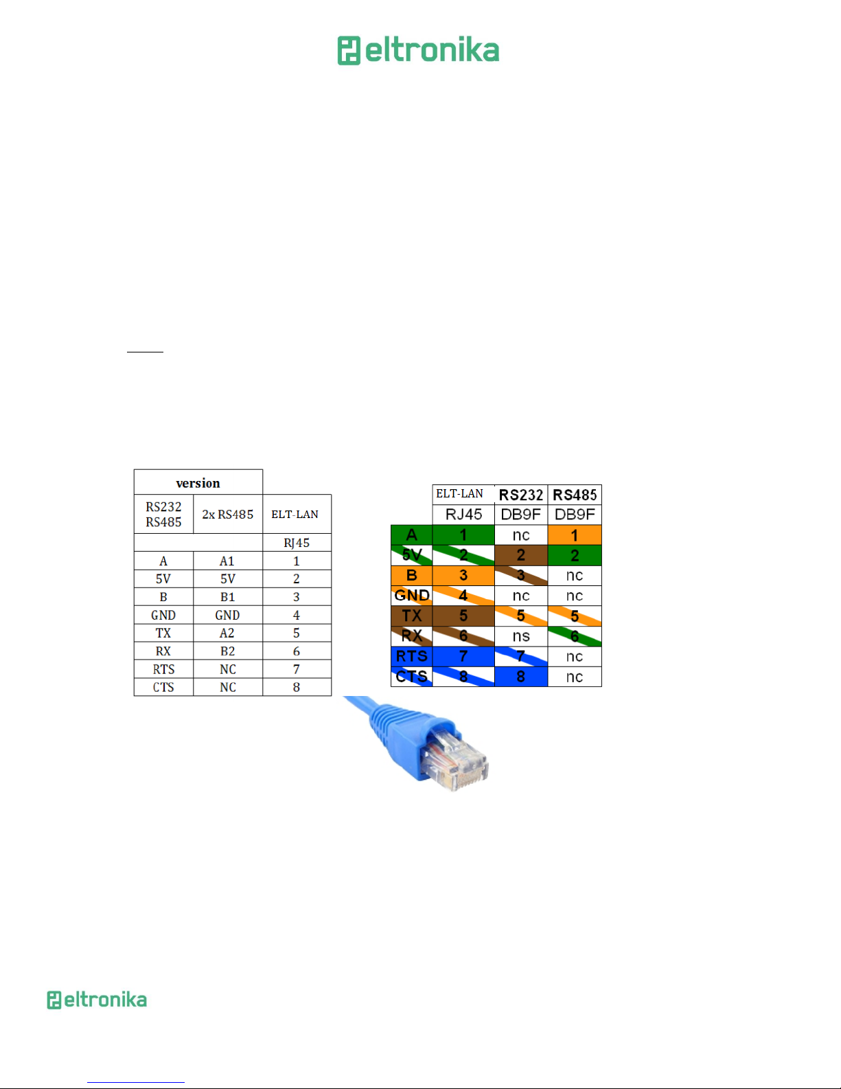
5.3.1.2 Modem serial port, either full RS232/RS485
Serial RS232/RS485 (through RJ-45 connector) is placed on front panel of
modem and it can be configured for special use as an option for customer.
5.3.1.3 RJ-45 connector
RJ-45 connector is placed on front panel of ELT-LAN modem and used for
communication with PC or laptop to plug cable for Ethernet. In order to start
configuration pages of modem plug UTP cable between RJ-45 of modem and RJ-45 of
your computer. Configuration pages are available in the web browser under IP address
specified on the modem (default address is 192.168.1.234).
Page 11

ELTRONIKA sp. z.o.o.
Ul. Warszawska 41 lok.7
05-092 Łomianki
[email protected]
www.eltronika.com
- Polska: +48 22 751 97 44
- Česká republika: +420 228 880 487
- Slovensko: +421 904 540 707
11
5.3.1.4 Power supply connector
In the ELT-LAN modem power supply 6V..30V care must be taken to ensure
“clean” power supply input and especially to avoid short transients on power supply
lines originating from inductive load switching. Otherwise internal module may be
permanently damaged.
5.3.1.5 Audio I/O
Audio Input and Output lines are available as option. There are three lines
available:
SPK/LINE OUT – external speaker or line out
LINE IN
MIC IN –microphone plug
Page 12
ELTRONIKA sp. z.o.o.
Ul. Warszawska 41 lok.7
05-092 Łomianki
[email protected]
www.eltronika.com
- Polska: +48 22 751 97 44
- Česká republika: +420 228 880 487
- Slovensko: +421 904 540 707
12
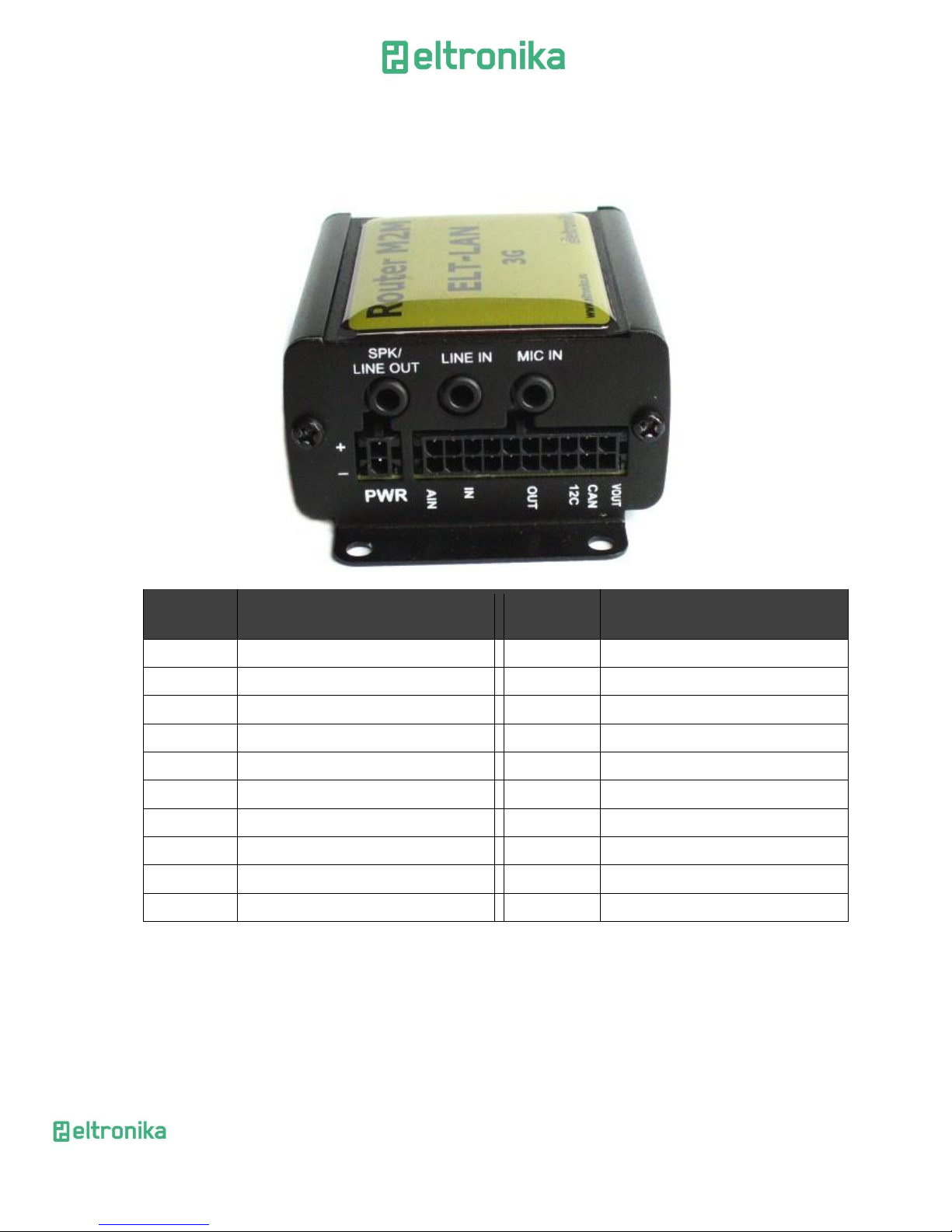
5.3.1.6 20-pin connector
ELT-LAN is available with 20pin connector as an option. Detailed description is
shown below.
PIN*
Upper row
Function
PIN*
Lower row
Function
1
ADC IN1
2
ADC IN2
3
DAC OUT
4 GND (not main supply input)
5
GND (not main supply input)
6 GND (not main supply input)
7
IN1
8
IN2 9 IN3
10
IN4
11
OUT1
12
OUT2
13
OUT3
14
OUT4
15
I2C SDA
16
I2C SCL
17
CAN L
18
CAN H
19
GND (not main supply input)
20
+3.3V output, 75mA max.
GND – ground. Do not connect directly with minus of power supply input.
1 19
2 20
Page 13
ELTRONIKA sp. z.o.o.
Ul. Warszawska 41 lok.7
05-092 Łomianki
[email protected]
www.eltronika.com
- Polska: +48 22 751 97 44
- Česká republika: +420 228 880 487
- Slovensko: +421 904 540 707
13
5.3.2 SIM card holders
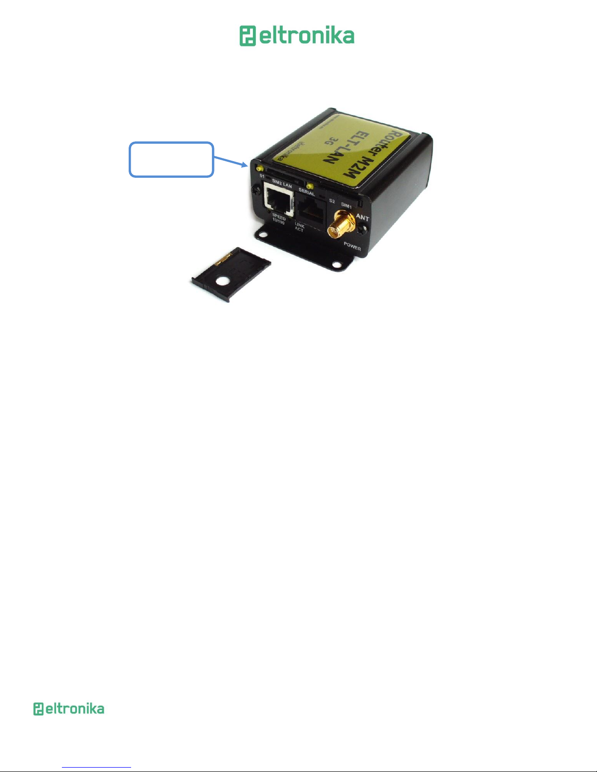
SIM card holders are placed in front panel of ELT-LAN. To insert SIM card into the
extractable holder push yellow button and take holder out. Place SIM card as show in
the picture. To operate the module in a GSM network, it is necessary to insert at least
one SIM card obtained from the network operator.
5.4 Product sticker
A production sticker includes the following information:
Product serial number
the CE marking
the 15-digit bar code
the model signature (ELT-LAN)
Push yellow
button to open
Page 14
ELTRONIKA sp. z.o.o.
Ul. Warszawska 41 lok.7
05-092 Łomianki
[email protected]
www.eltronika.com
- Polska: +48 22 751 97 44
- Česká republika: +420 228 880 487
- Slovensko: +421 904 540 707
14
6 Basic features and services
Basic features and available services are contained in table below.
Feature /
service
Description
Supported
bands
All variants:
• GSM 900 Class 4 (2W)
• DCS 1800 Class 1 (1W)
• EDGE 900MHz Class E2 (0.5W)
• EDGE 1800MHz Class E2 (0.4W)
HSPA+ variant:
• WCDMA FDD B1, B2, B4, B5, B8 Class 3 (0.25W)
UMTS variant:
• WCDMA FDD B1, B8 Class 3 (0.25W)
LTE variant:
• WCDMA FDD B1, B5, B8 Class 3 (0.25W)
• LTE FDD B3, B7, B20 Class 3 (0.2W)
Data features
HSPA+ (downlink 21 Mbit/s, uplink 5,76 Mbit/s)
UMTS (downlink 7,2 Mbit/s, uplink 5,76 Mbit/s)
EDGE (Multi-slot class 10, max BR downlink 236,8 Kb/s)
GPRS (Multi-slot class 10, max BR downlink 85,6 Kb/s)
CSD (Max BR 14,4 Kb/s)
Embedded protocols: TCP/IP, UDP/IP, SSL, HTTP, HTTPS, FTP, SMTP, POP3, IBM MQTT
Class B GSM 07.10 multiplexing protocol
WiFi
Standard:
• 802.11b/g/n, 802.3, 802.3u
Date rate
• up to 150 Mbps
Power supply
Nominal voltage range: 6V-30V
Maximum continuous (average) supply power: 5W
Peak (momentary) supply current: 1 A
Interfaces
(typical
version)
GSM antenna connector: SMA
1x SIM Card: 1.8V, 3V standards
RS232 and RS485 via RJ-45
RJ-45 connector (x2)
miniUSB (OTG)
power supply connector
Options*
Dual SIM
I/O interfaces (CAN, 3.3V output,)
Audio I/O
WiFi antenna connector: SMA
Other
Max. Dimensions: 83 x 60 x 34 mm (w/ connectors)
Min. -20°C Max. 45°C
*options, depending on customer’s request
Page 15
ELTRONIKA sp. z.o.o.
Ul. Warszawska 41 lok.7
05-092 Łomianki
[email protected]
www.eltronika.com
- Polska: +48 22 751 97 44
- Česká republika: +420 228 880 487
- Slovensko: +421 904 540 707
15
7 Using the modem
7.1 Setting up the modem
To set the modem, do the following steps:
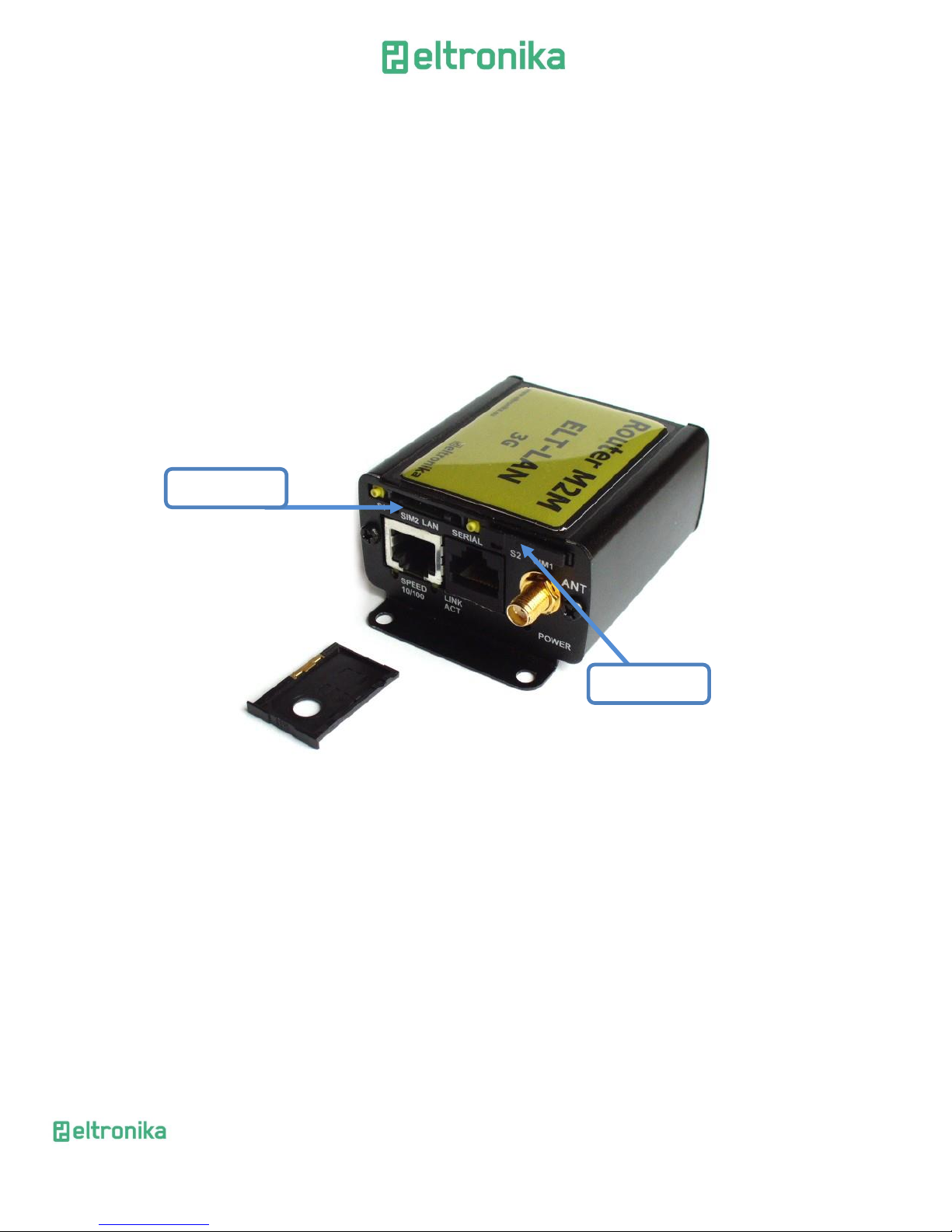
7.1.1 Inserting SIM card(s)
Push yellow button place on front panel and take SIM holder drawer out.
Place SIM card(s) in the holder(s) as shown in the picture:
*modems are available with one or two SIM cards
Master SIM
Slave SIM*
Page 16
ELTRONIKA sp. z.o.o.
Ul. Warszawska 41 lok.7
05-092 Łomianki
[email protected]
www.eltronika.com
- Polska: +48 22 751 97 44
- Česká republika: +420 228 880 487
- Slovensko: +421 904 540 707
16
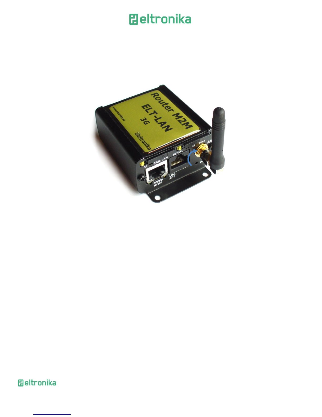
7.1.2 Connecting antenna
Connect the GSM antenna to the SMA connector, or both GSM and GPS in
optional versions of the modem.
Page 17
ELTRONIKA sp. z.o.o.
Ul. Warszawska 41 lok.7
05-092 Łomianki
[email protected]
www.eltronika.com
- Polska: +48 22 751 97 44
- Česká republika: +420 228 880 487
- Slovensko: +421 904 540 707
17
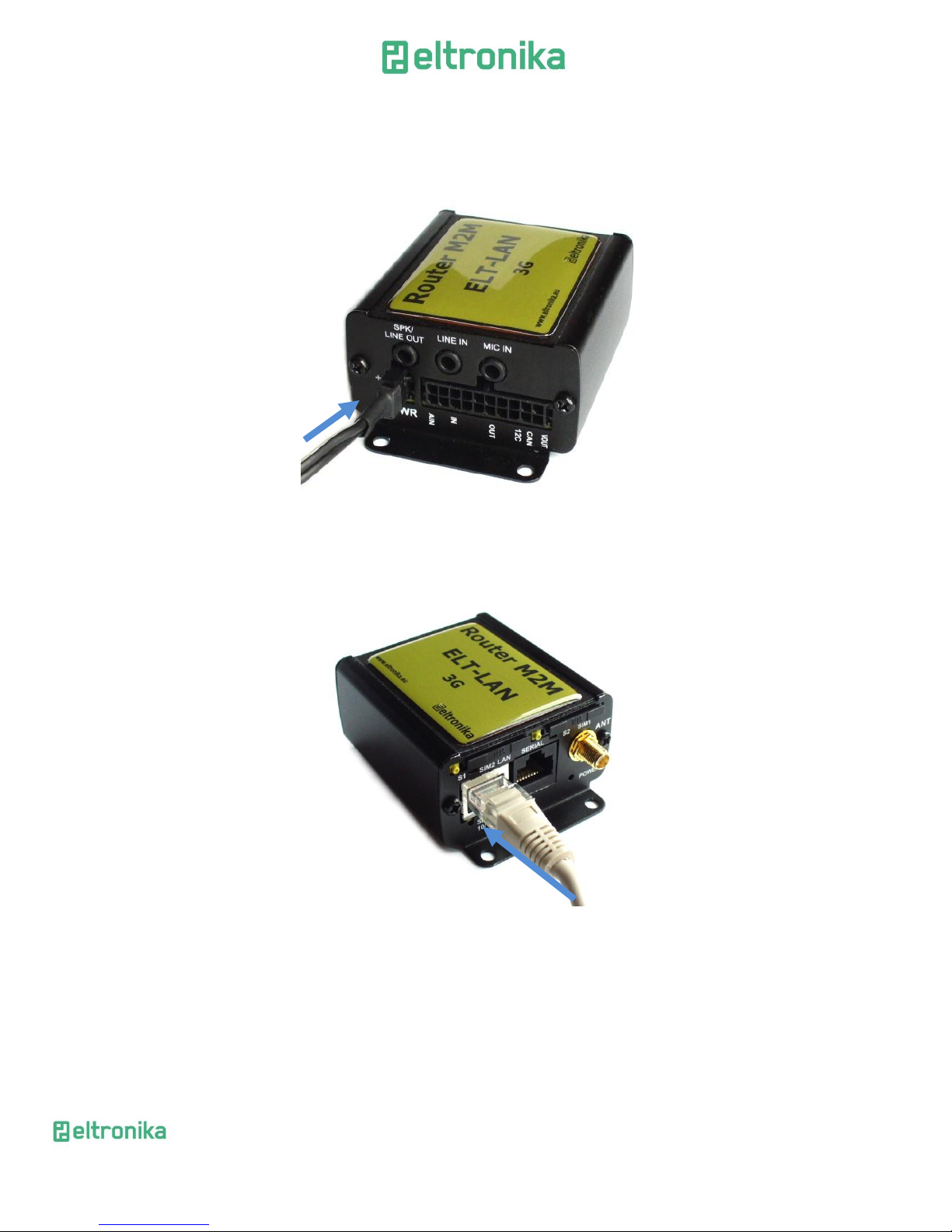
7.1.3 Connecting power supply cable
Connect power supply cable into power supply connector
7.1.4 Connecting UTP cable with RJ-45
Plug UTP or similar cable to RJ-45 plug.
Page 18

ELTRONIKA sp. z.o.o.
Ul. Warszawska 41 lok.7
05-092 Łomianki
[email protected]
www.eltronika.com
- Polska: +48 22 751 97 44
- Česká republika: +420 228 880 487
- Slovensko: +421 904 540 707
18
7.2 Modem configuration
Modem is configured via web browser making it portable and easy to use. Modem
configuration is described below in following sections. Modem settings are divided into
sections which allows user to easily find option needed. When switching tabs settings
are automatically saved in modem cache, to save settings permanently and apply them
click Save Settings in menu. You can also discard changes by choosing appropriate
option from the bottom of the menu.
WARNING: Cache is cleared on modem reset or pulling the power cable out.
WARNING: Not all tabs are available on every modem version.
7.2.1 Setting up the connection
After you connect all necessary cables (see 7.1 Setting up the modem) you can set
up connection. Connect UTP cable to your computer and go to Internet protocol TCP/IP
properties (Network connections -> Local Area Connection ->Internet protocol
TCP/IP-> Properties) and set your IP address as 192.168.1.x. Please read how to
change TCP/IP settings of your network card in this thread (for Windows 7):
http://windows.microsoft.com/en-us/windows/change-tcp-ip-
settings#1TC=windows-7
Now modem will connect your computer and its configuration page can be seen
by going to default IP address in your browser 192.168.1.234.
7.2.2 Modem status page
Go to your web browser and put IP address 192.168.1.234. You will be asked for
username and password. By default it is:
Username: admin
Password: 12345
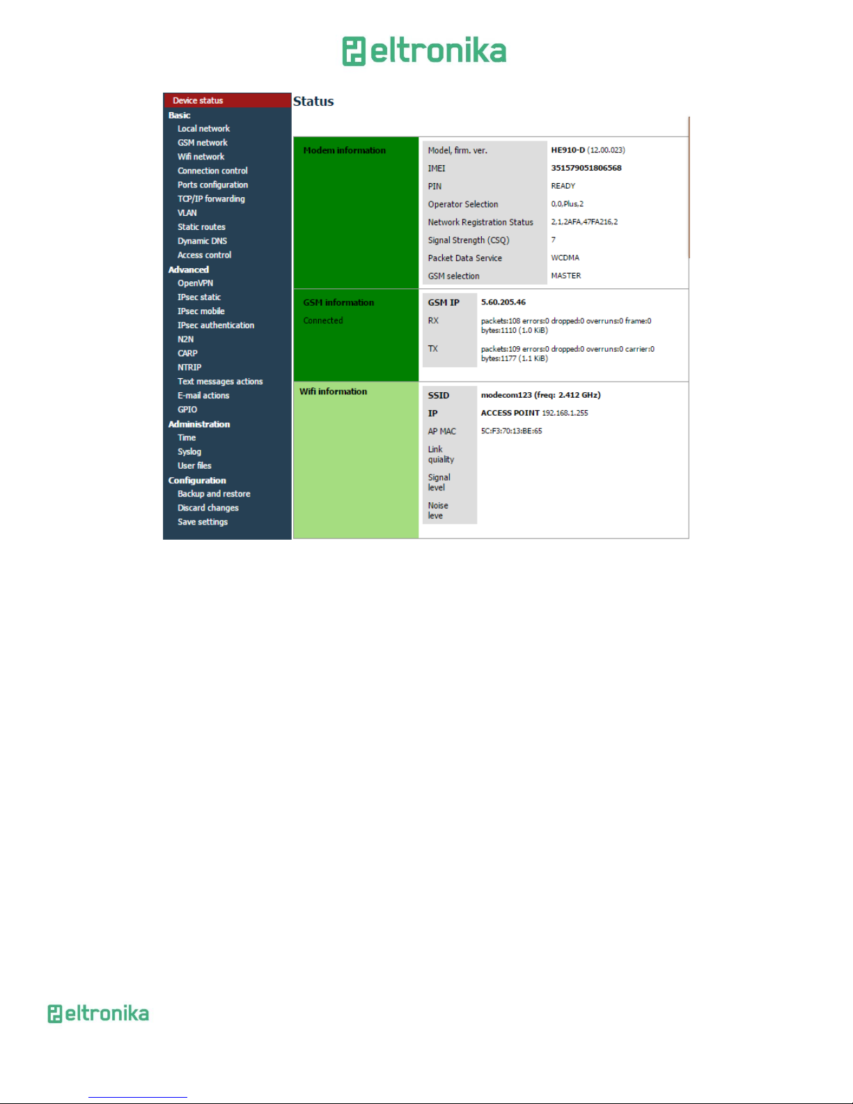
If everything is configured correctly you should see following screen:
Page 19
ELTRONIKA sp. z.o.o.
Ul. Warszawska 41 lok.7
05-092 Łomianki
[email protected]
www.eltronika.com
- Polska: +48 22 751 97 44
- Česká republika: +420 228 880 487
- Slovensko: +421 904 540 707
19
This is Status page of your modem. Here you can see if modem is
connected/disconnected from net and its parameters and parameters of PPP
connection.
Page 20
ELTRONIKA sp. z.o.o.
Ul. Warszawska 41 lok.7
05-092 Łomianki
[email protected]
www.eltronika.com
- Polska: +48 22 751 97 44
- Česká republika: +420 228 880 487
- Slovensko: +421 904 540 707
20
7.2.3 Local network
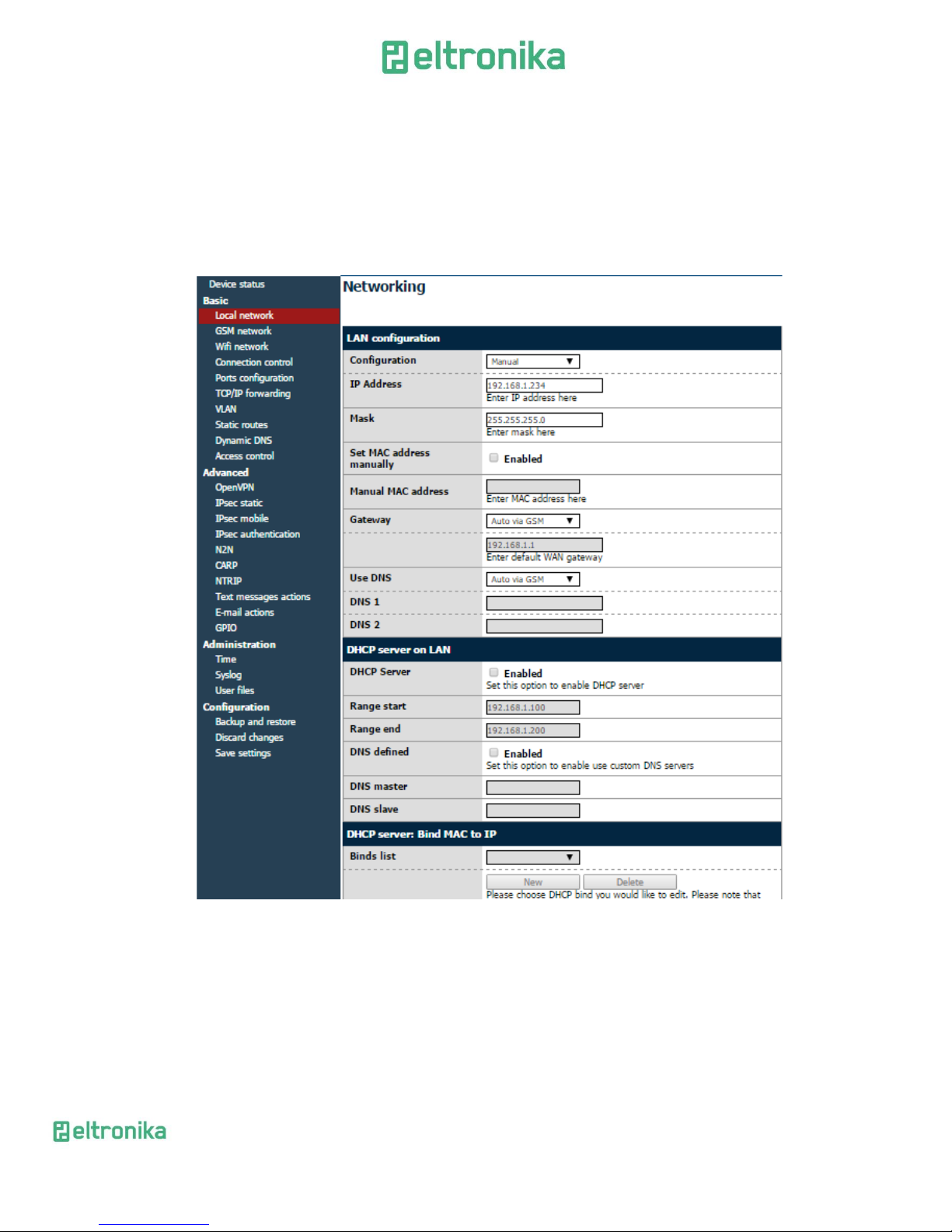
On LAN configuration page you can find essential parameters needed for LAN
connection. Here you can set IP Address (or set it to be downloaded via DHCP), mask,
default gateway, DNS addresses. Last two options can be entered manually or
downloaded automatically via GSM or DHCP. Modem can also work as DHCP server-you
can define its range and set list of IP-MAC binds.
Page 21
ELTRONIKA sp. z.o.o.
Ul. Warszawska 41 lok.7
05-092 Łomianki
[email protected]
www.eltronika.com
- Polska: +48 22 751 97 44
- Česká republika: +420 228 880 487
- Slovensko: +421 904 540 707
21
7.2.4 GSM network / WiFi network
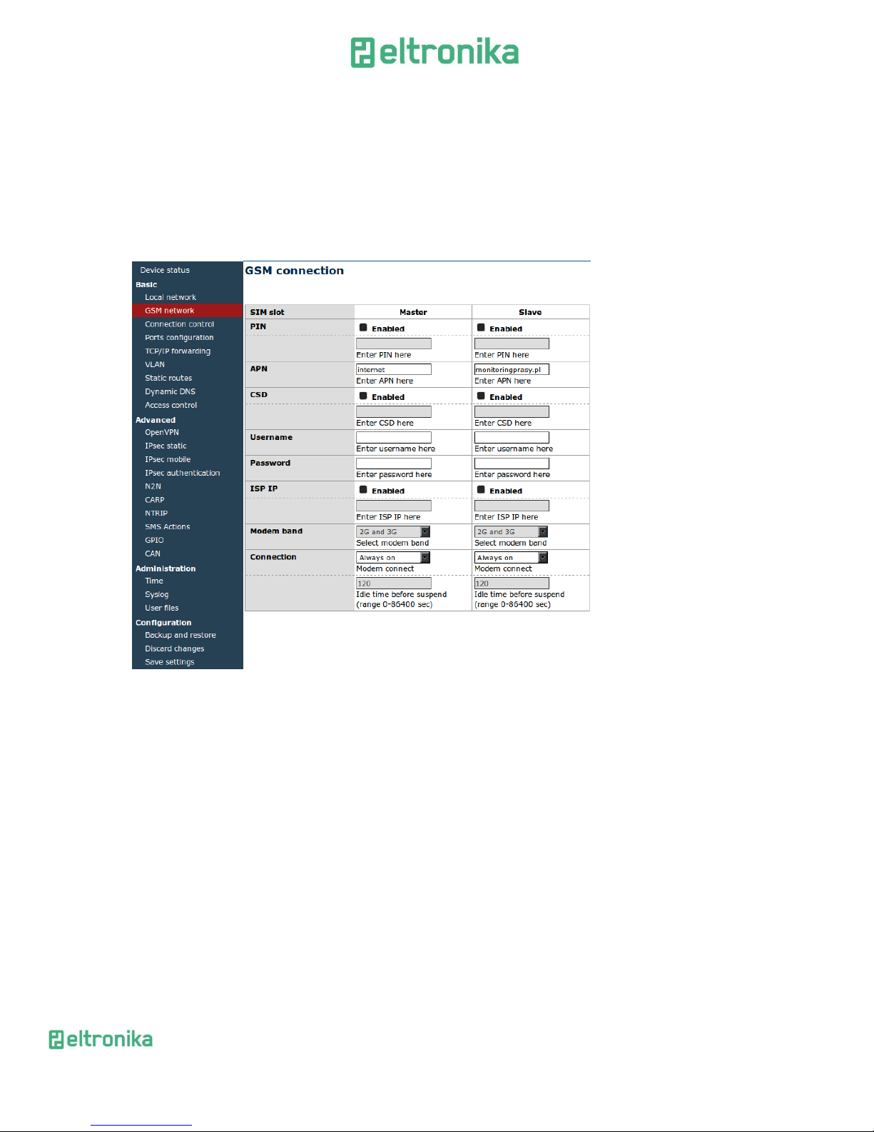
On ISP Master page you can define internet connection parameters (APN,
username, password, CSD, ISP IP and Modem band) for one or two SIM cards (depending
on modem version). To use internet you should know those parameters - they are
essential for getting access to internet. The parameters should be ensured by your
mobile network provider. You can find them by contacting your GSM network provider
or visiting its website.
To enter the PIN for SIM card you need to mark “Enable” field and then fill the
field below with correct PIN. Outgoing calls are made always on MASTER SIM card.
Page 22
ELTRONIKA sp. z.o.o.
Ul. Warszawska 41 lok.7
05-092 Łomianki
[email protected]
www.eltronika.com
- Polska: +48 22 751 97 44
- Česká republika: +420 228 880 487
- Slovensko: +421 904 540 707
22
WiFi
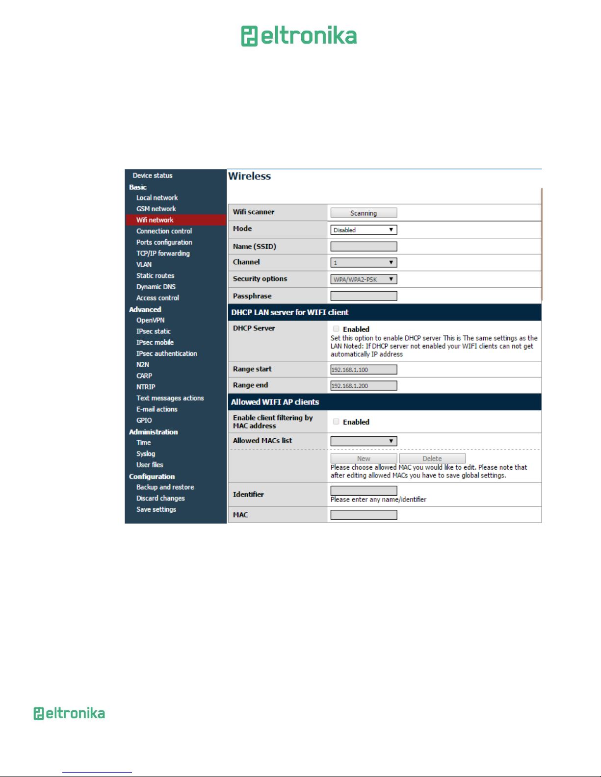
“WiFi network” tab is available only in ELT-LAN with WiFi option. In this menu
you can set parameters of your WiFi connection. To scan all available networks please
use “Scanning” button. You will redirect to a page with a list of networks. You can set a
WiFi mode (Access point or Station), fill a name and password of selected network. You
can also enable DHCP server and AP clients.
Page 23
ELTRONIKA sp. z.o.o.
Ul. Warszawska 41 lok.7
05-092 Łomianki
[email protected]
www.eltronika.com
- Polska: +48 22 751 97 44
- Česká republika: +420 228 880 487
- Slovensko: +421 904 540 707
23
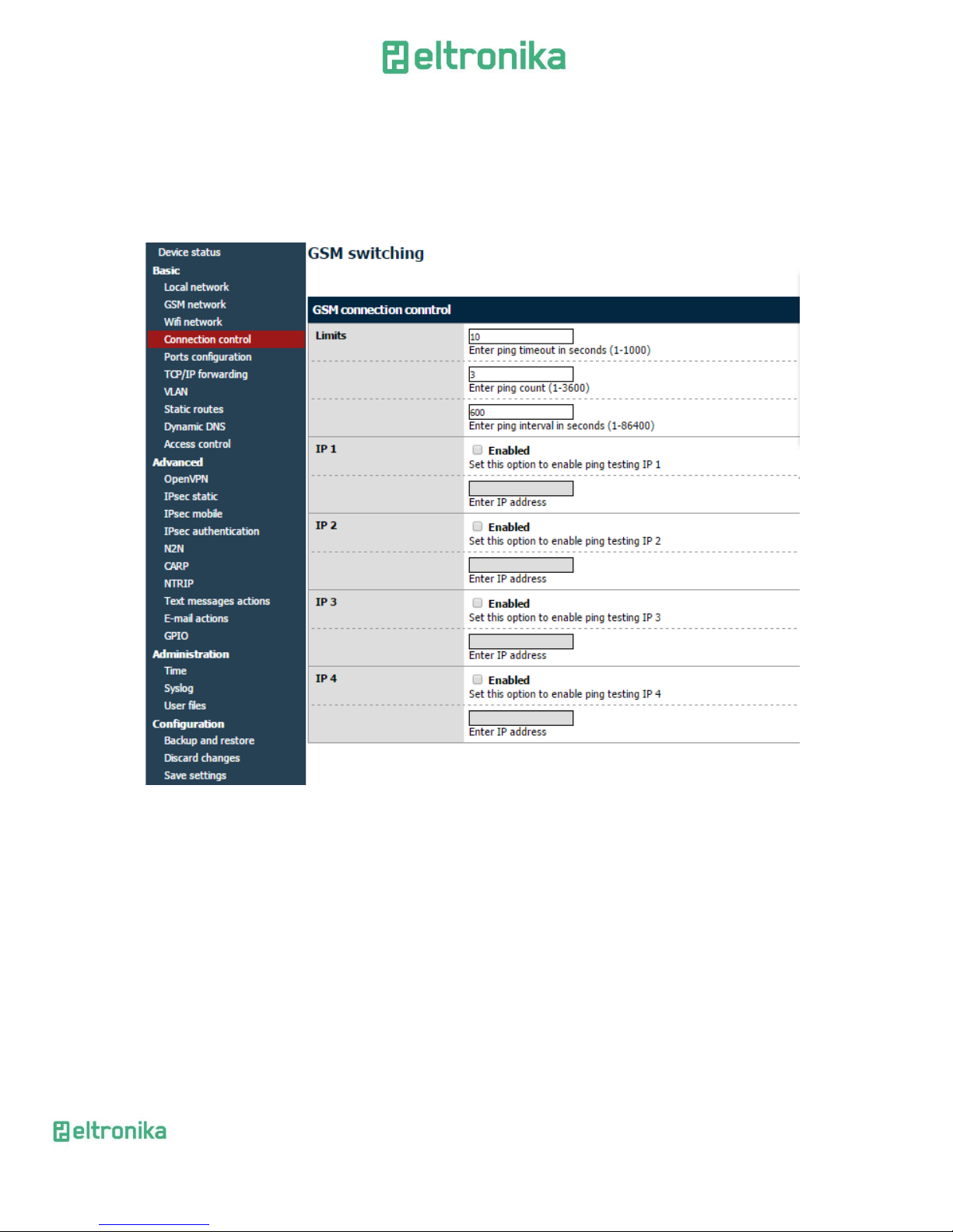
7.2.5 Connection control
Here you can set parameters of switching between two SIM cards. You can define
time for ping and ping counter for 4 IP addresses you choose. In example (picture) here
after 3 pings that take 10 seconds each card will change from Master to Slave or
opposite.
Page 24
ELTRONIKA sp. z.o.o.
Ul. Warszawska 41 lok.7
05-092 Łomianki
[email protected]
www.eltronika.com
- Polska: +48 22 751 97 44
- Česká republika: +420 228 880 487
- Slovensko: +421 904 540 707
24
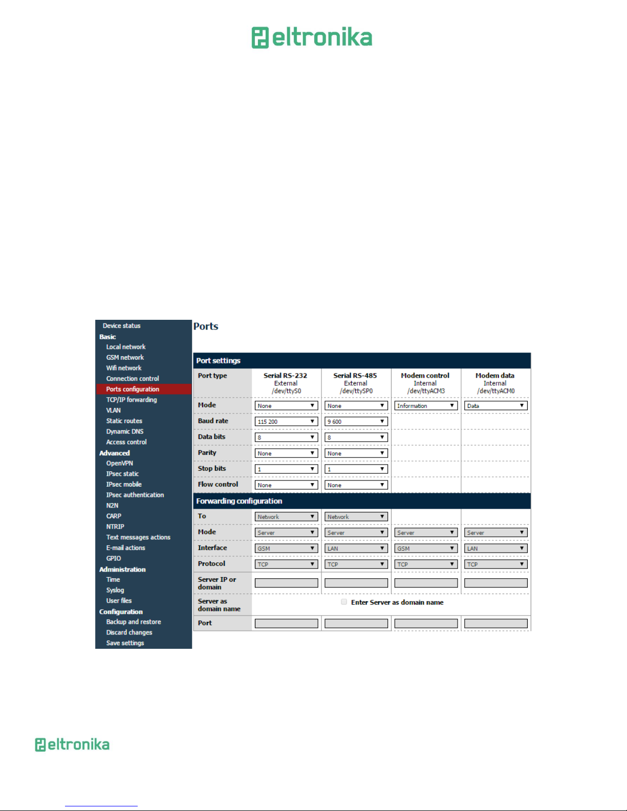
7.2.6 Ports configuration
You are able to set port settings under RS232/RS485 Port page. There are 3
configurable ports: /dev/ttyS0, /dev/ttyACM0 and /dev/ttyS1 or /dev/ttyUSB0
(depending on modem version).
Every port can be set to different mode. On /dev/ttyS0 you can set terminal,
ModBus gateway or NTRIP mode. Two other ports can work as modem port (modem
control and modem data) or SMS receiving port (see also: SMS Actions section).
Every port can also be set to forwarding mode that allows user to forward it to
TCP/UDP port (as server or client). Port /dev/ttyS0 can also be forwarded to modem
control or modem data port-in that case no other mode can be set on that port.
Setting certain modes on /dev/ttyS0 and /dev/ttyS1 (LTE modem variant only)
enables setting port parameters: baud rate, data bits, parity checking and protocol. If
parameter is inactive that means that user can't control it in currently set mode.
Page 25
ELTRONIKA sp. z.o.o.
Ul. Warszawska 41 lok.7
05-092 Łomianki
[email protected]
www.eltronika.com
- Polska: +48 22 751 97 44
- Česká republika: +420 228 880 487
- Slovensko: +421 904 540 707
25
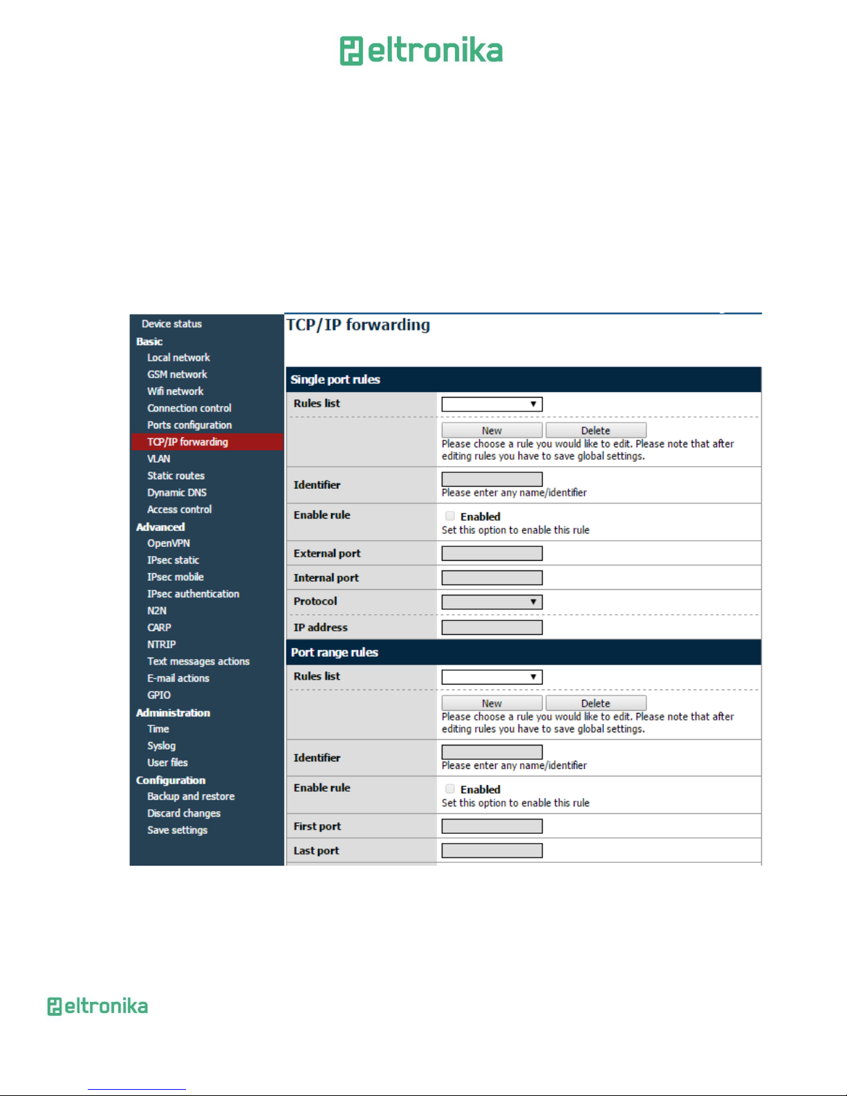
7.2.7 TCP/IP forwarding
You can forward single port or port ranges onto certain IP address To add new
rule for single port, enter TCP/IP Forwarding tab. In Single port rules section click
button New and enter all necessary information: identifier, check Enabled field, enter
external and internal port, choose protocol (TCP or UDP) and enter IP address. When
adding new rule or switching tab, currently edited rule is automatically saved. You can
delete it (or any other rule) by pressing Delete button. After changes click Save Settings
to save whole configuration. You can edit port range rules in the same way in Port range
rules section. You can also set IP address of demilitarized zone in DMZ section.
Page 26
ELTRONIKA sp. z.o.o.
Ul. Warszawska 41 lok.7
05-092 Łomianki
[email protected]
www.eltronika.com
- Polska: +48 22 751 97 44
- Česká republika: +420 228 880 487
- Slovensko: +421 904 540 707
26
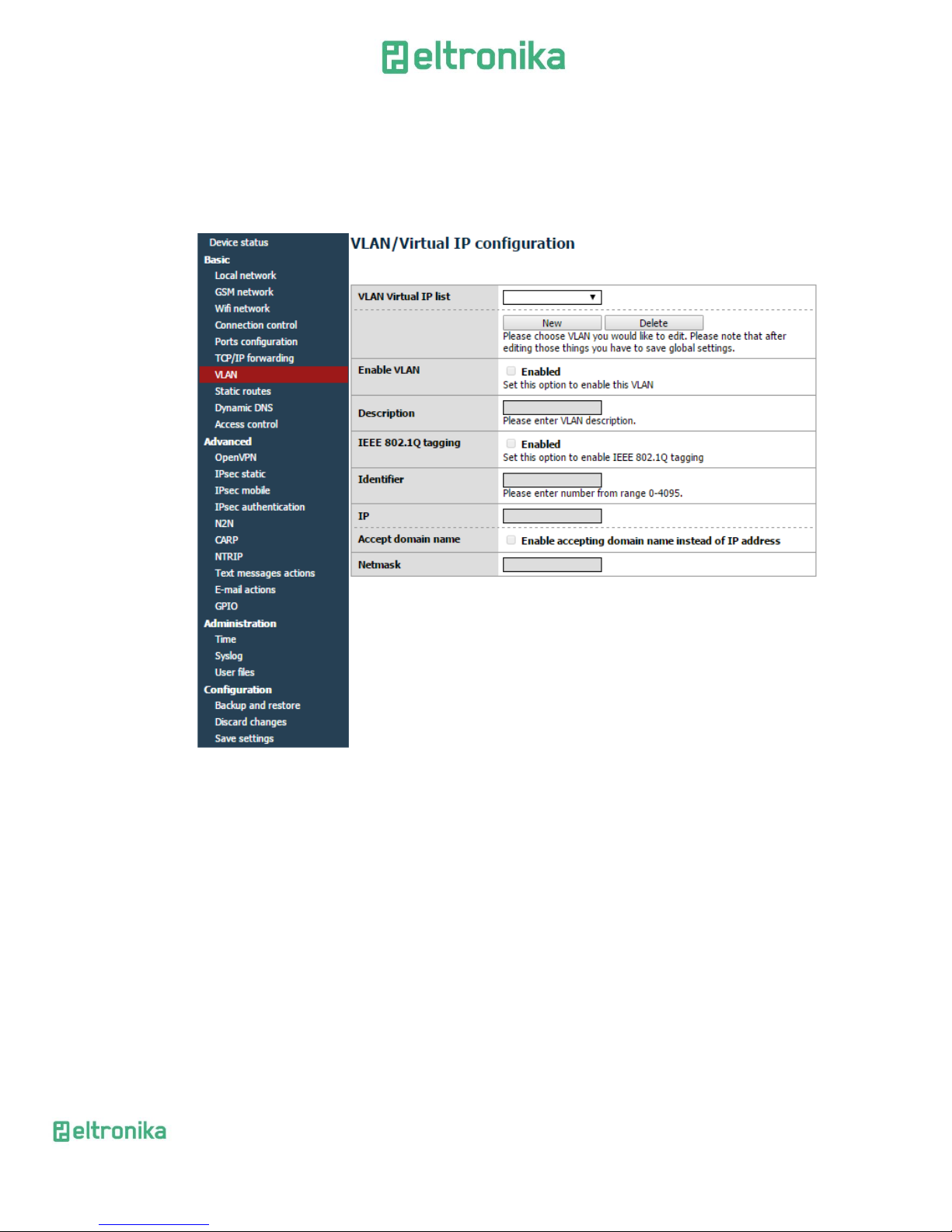
7.2.8 VLAN
VLAN tab enables user to create virtual IP addresses. You can define IP, netmask
and identifier from range 0-4095. If you enable IEEE 802.1Q tagging Virtual IP becomes
part of VLAN.
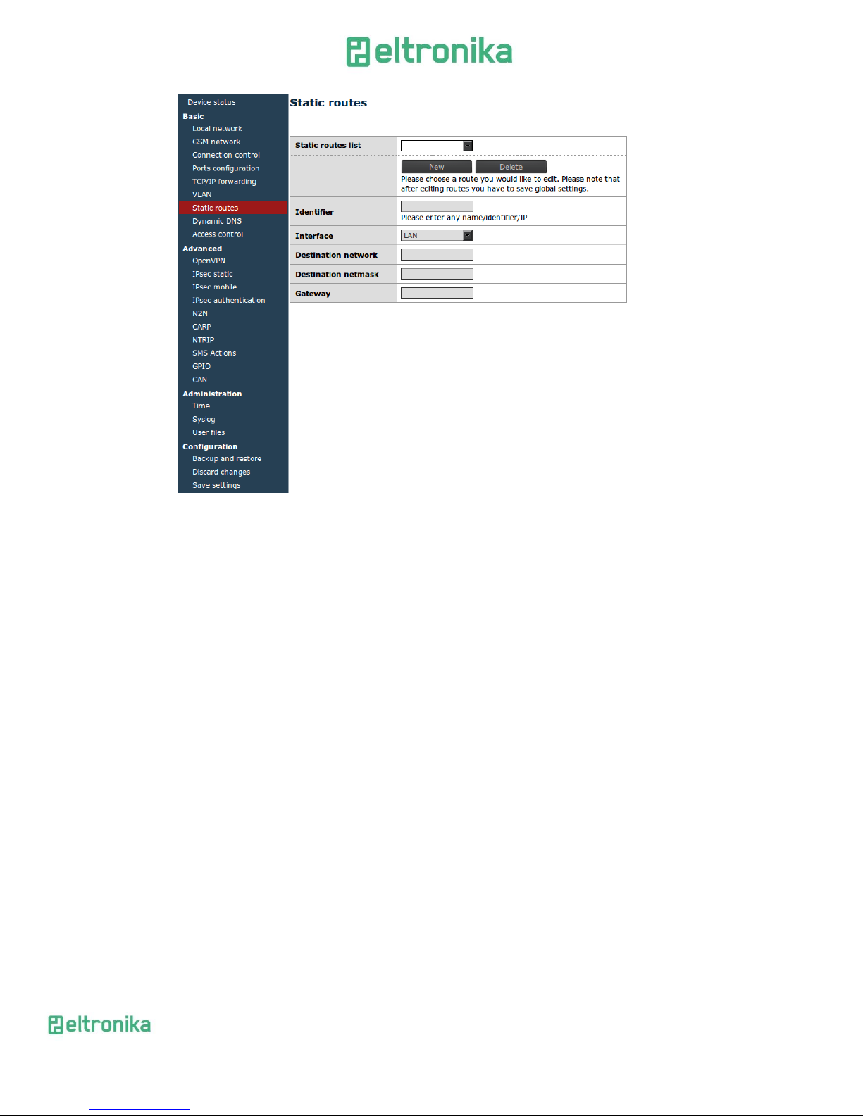
7.2.9 Static routes
Under static routes tab you can define your own routings. Please click Add new
button to add new routing. Enter identifier (used only to distinguish routings in www
configuration), choose interface, enter destination network, netmask and gateway.
Page 27
ELTRONIKA sp. z.o.o.
Ul. Warszawska 41 lok.7
05-092 Łomianki
[email protected]
www.eltronika.com
- Polska: +48 22 751 97 44
- Česká republika: +420 228 880 487
- Slovensko: +421 904 540 707
27
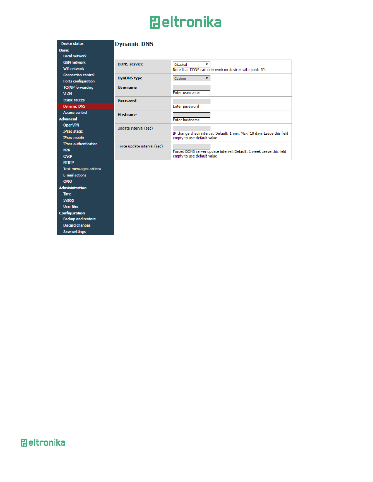
7.2.10 Dynamic DNS
Dynamic DNS is a service which allows user to make your device available under
specific www address regardless of its IP changes. In order to do that you must create an
account on one of web pages that are supported by ELT modem (currently DynDNS.org
or No-IP.com). After creating account, please enter necessary information in Dynamic
DNS tab of www configuration: your service provider, in case of DynDNS its type,
username, password, host name and two intervals. Update interval is time between two
checks whether IP address had changed. Forced update interval is time between
updating IP data regardless of IP change. Please last two fields empty to use default
value if you're not sure what to input there.
Page 28
ELTRONIKA sp. z.o.o.
Ul. Warszawska 41 lok.7
05-092 Łomianki
[email protected]
www.eltronika.com
- Polska: +48 22 751 97 44
- Česká republika: +420 228 880 487
- Slovensko: +421 904 540 707
28
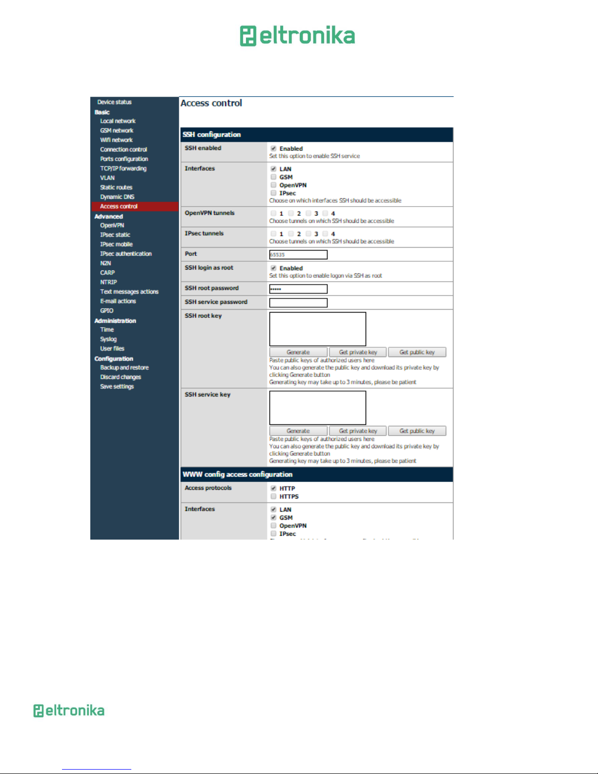
7.2.11 Access control
First section of Access Control tab allows you to configure SSH protocol. You can
turn it on or off, set on which port and interfaces (also OpenVPN and IPsec tunnels) it
should be accessible. You can also toggle logging via SSH as root and change/delete
passwords/keys for root and service user. Remember to save whole configuration after
changing password by pressing Save Configuration button from main menu. Deleting
password means that it won't be needed to log on. When logging via SSH, key
authentication has higher priority than password. That means that user with authorized
key won't be prompted for a password and user without key will be able to login using
password. You can paste multiple keys into SSH root key and SSH service key fields.
ATTENTION: Service account is used to upgrade firmware. Turning SSH off will
disable firmware upgrades.
You can generate necessary keys directly on modem. Press the Generate button
and wait for a while-the process can take few minutes. You should not change settings or
switch tabs then. After the generation the message will be displayed. Public key will be
automatically pasted into the keys field (if the field wasn't empty before pressing the
button, its contents will be saved, the newly generated key will appear first on the list).
From now you will be able to download private and public keys by pressing Get private
Page 29
ELTRONIKA sp. z.o.o.
Ul. Warszawska 41 lok.7
05-092 Łomianki
[email protected]
www.eltronika.com
- Polska: +48 22 751 97 44
- Česká republika: +420 228 880 487
- Slovensko: +421 904 540 707
29
key and Get public key buttons. To login using the key under Linux, you have to
download private key, change its name to id_rsa and put it in /home/user/.ssh folder.
In WWW config access section you can toggle HTTP/HTTPS access www
configuration and change ports and interfaces (OpenVPN and IPsec tunnels also) on
which they will be available. You can also change password for www configuration (the
change will be immediate, no saving configuration is needed). For security reasons
disabling both HTTP and HTTPS is not possible.
Page 30

ELTRONIKA sp. z.o.o.
Ul. Warszawska 41 lok.7
05-092 Łomianki
[email protected]
www.eltronika.com
- Polska: +48 22 751 97 44
- Česká republika: +420 228 880 487
- Slovensko: +421 904 540 707
30
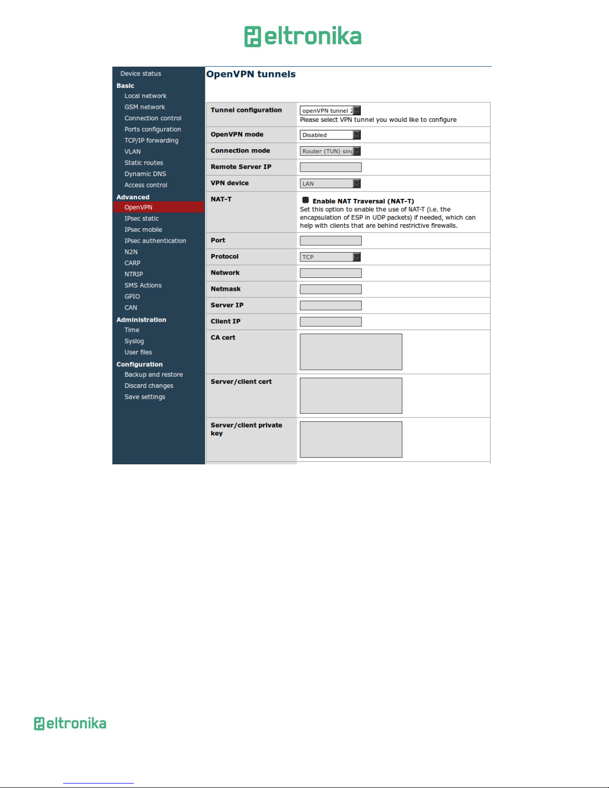
7.2.12 Open VPN
You can connect your modem to a VPN network or create your own one using
OpenVPN software. It is possible to create up to four VPN connections (tunnels). To view
and change settings of any of tunnels select it from Tunnel configuration list under
OpenVPN tab. Then choose if modem should be server or client and connection type: tun
or tap. Tun connection can be single- or multiclient. Depending on what you choose
here, you will later need to enter client/server IP addresses or network and netmask.
If the device should be server, please enter port on which it should listen for
connections (the default VPN port is 1194, remember to open the port you chose under
the firewall tab). Next, please select network device on which the connection should be
held: eth (external RJ45 port) or ppp (connection via mobile network). It is also
necessary to choose network protocol: TCP or UDP (use the second option if you are not
sure what to choose). For tun mode user should also enter server and client IPs
(we advise you to use addresses from 10.x.x.x pool). For tap mode please enter VPN sub
network address and net mask (for example 10.1.0.0 and 255.255.255.0). In most cases,
your device will reserve first IP address from the pool (that is 10.1.0.1 if you are using
10.1.0.0 network).
If the device is set into client mode, in addition to settings same as those for
server, you should input VPN server's IP in Remote Server IP field and its listening port
in the Port field.
After filling in all necessary information user should fill in four certificate fields.
The certificates should be generated on any PC (see VPN online help for more
information). The contents of files should be pasted into appropriate fields of
configuration. You can improve security of your VPN connection by entering TLS key
into the TLS key field on every device in VPN network.
The last setting is toggling LZO compression (we advise you to enable it to
improve network communication) and adding extra configuration parameters in
Additional configuration field.
Page 31
ELTRONIKA sp. z.o.o.
Ul. Warszawska 41 lok.7
05-092 Łomianki
[email protected]
www.eltronika.com
- Polska: +48 22 751 97 44
- Česká republika: +420 228 880 487
- Slovensko: +421 904 540 707
31
7.2.13 Ipsec static/Ipsec mobile
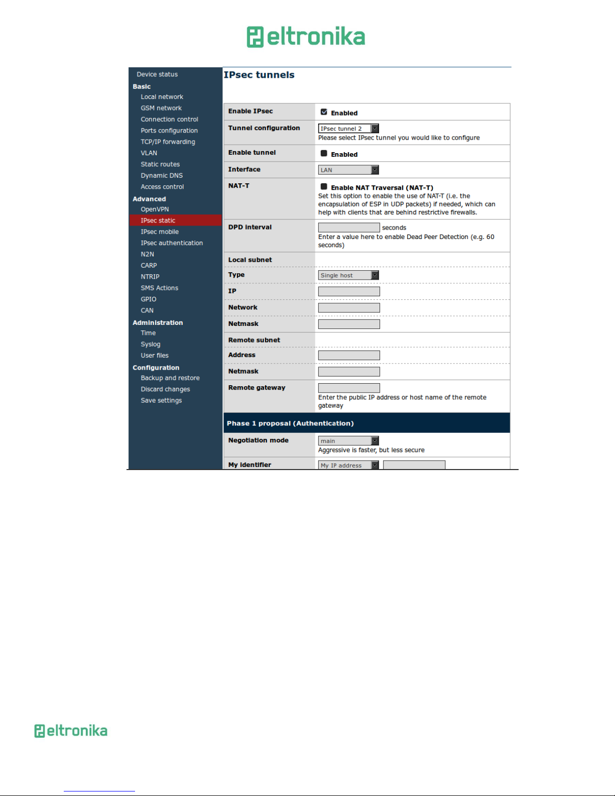
IPsec is group of internet protocols that enables user to create safe connection
between devices. To configure such connection on ELT modem you need to go through
three tabs of configuration: Tunnels, Mobile Clients, Keys and Certificates. First of all,
you need to enable IPsec under Tunnels tab. Below this option there is a combo box that
enables you to switch between different tunnel configurations. If you want to enable
specific tunnel, please select Enable tunnel checkbox. Then specify network interface on
which the connection will be held. It is impossible to discuss all ways to create IPsec
connection, so we have described sample configuration below.
Page 32

ELTRONIKA sp. z.o.o.
Ul. Warszawska 41 lok.7
05-092 Łomianki
[email protected]
www.eltronika.com
- Polska: +48 22 751 97 44
- Česká republika: +420 228 880 487
- Slovensko: +421 904 540 707
32
Let's say we want to connect two ELT modems with following IP numbers:
123.45.67.1, 123.45.67.2. First option, DPD interval is time after which the connection is
closed if the other device is not responding. You can put any value here, we will enter
3600 seconds. Then you have to choose local subnet that will be available on remote
side of the connection. It can be single host, network or LAN subnet. Let's say we will be
connecting more devices later so we choose network. On first modem we enter following
settings: IP=192.168.36.1, Network=192.168.36.0 and Netmask=255.255.255.0. The IP
must be set properly according to the network and netmask. Next step is entering
remote subnet. The local subnet on first device must match remote subnet on the second
device and vice versa. We have specified local subnet on second modem with following
settings: IP=192.168.35.1, Network=192.168.35.0, Netmask=255.255.255.0, so on the
first modem we enter following remote subnet: Address=192.168.35.0,
Netmask=255.255.255.0. After specifying local and remote subnets, you should enter
remote gateway which should be other device's IP. In our case we enter 123.45.67.2 on
first modem and 123.45.67.1 on second one.
Afterwards we have to define first phase of the proposal. We choose negotiation
mode-aggressive is less secure, but faster than main. Next setting is device's identifier.
The most common setting is My IP address for PSK authentication and RSA Cert subject
for RSA certificates. Now, please choose encryption, hash algorithm and DH key groupthey must be the same on both sides of connection. Blowfish encryption is usually the
fastest and AES is the slowest but most secure. You can optionally set lifetime of phase 1
or leave the field blank to use default value. The most important setting of phase 1 is
choosing authentication method: Pre-shared key is like password, you have to enter the
same key on both sides. More sophisticated authentication method is using RSA
certificates, but you need to generate certificate and key for every device. You have two
options here: either input other device's certificate in Peer certificate field or add CA
certificate (we will cover that topic later).
Page 33
ELTRONIKA sp. z.o.o.
Ul. Warszawska 41 lok.7
05-092 Łomianki
[email protected]
www.eltronika.com
- Polska: +48 22 751 97 44
- Česká republika: +420 228 880 487
- Slovensko: +421 904 540 707
33
In the second phase of proposal please specify the protocol (ESP is authentication
with encryption, AH is authentication only), encryption algorithm, hash algorithm and
PFS key group. Please note that you can choose multiple algorithms, but at least one
should match on both sides of the connection. The last setting is phase 2 lifetime (leave
field empty for using default value).
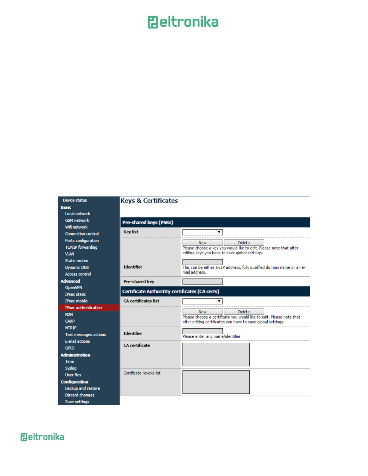
After configuring all settings remember to save configuration. The configuration
of IPsec connection is finished unless you chose to authenticate with RSA certificates
and CA certificate. In that case click on Keys and Certificates tab. Here you can add
multiple Pre-shared keys and CA certificates. Adding both is similar, so we will explain
only adding CA certificates. To add new one, please click on Add new button. Specify
Identifier (which is used only for distinguish them in www configuration), paste CA
certificate and certificate revoke list. Last field is optional and lets you ban users that
shouldn't be allowed to join your network anymore.
Page 34
ELTRONIKA sp. z.o.o.
Ul. Warszawska 41 lok.7
05-092 Łomianki
[email protected]
www.eltronika.com
- Polska: +48 22 751 97 44
- Česká republika: +420 228 880 487
- Slovensko: +421 904 540 707
34
IMPORTANT: After filling in fields click Save button and then save whole
configuration by clicking Save settings. If you want to delete certificate, choose it from
the list, click Delete button and then save whole configuration.
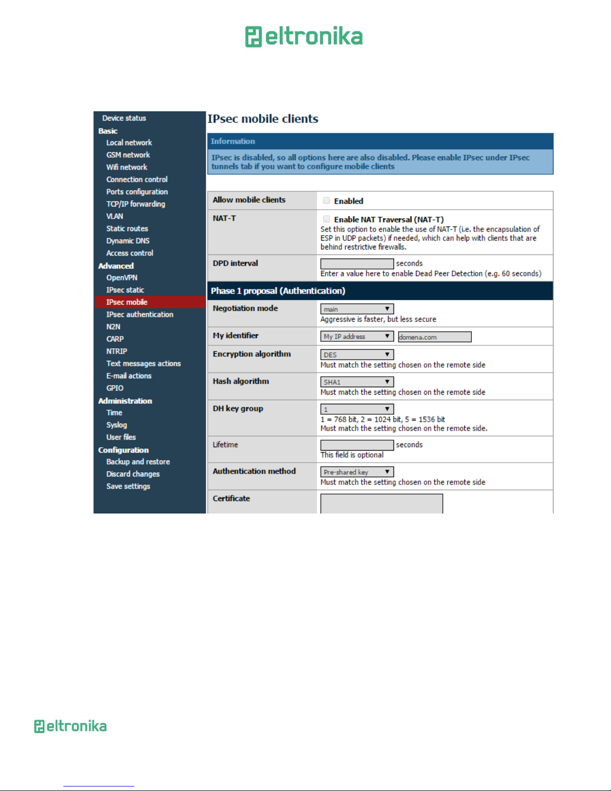
It is possible to create IPsec connection with non-static-IP-devices. In order to do
this please click Mobile clients tab. Configuration is similar to the tunnel configuration,
but there are less settings (for example there is no PSK field-you should add pre-shared
keys for mobile clients in Keys and Certificates tab).
IMPORTANT: When configuring IPsec connection you will sometimes want to
add custom routing. This topic is covered in next section.
Page 35

ELTRONIKA sp. z.o.o.
Ul. Warszawska 41 lok.7
05-092 Łomianki
[email protected]
www.eltronika.com
- Polska: +48 22 751 97 44
- Česká republika: +420 228 880 487
- Slovensko: +421 904 540 707
35
7.2.14 Generating SSL certificates
In order to use SSL authentication creating few files and copying them into
adequate fields under OpenVPN or IPsec tabs of www configuration is needed. This can
be done using PC with Linux and openssl installed. There is also Windows version of
software available at http://gnuwin32.sourceforge.net/packages/openssl.htm.
At first we need to create folder, in which all our keys and certificates will be
stored. Let's say it will be ~/keys. We create two files in it: list of certificates and file
enumerating them:
touch index.txt
echo 00 > serial
and subdirectories, where the certificates and keys will be stored:
mkdir private certs newcerts crl
In order to create certificates, the certificate authority (CA) is needed . It is ,,main''
certificate used to create other certificates. After creating private CA key:
openssl genrsa -des3 -out private/cakey.pem 1024
Warning: please remember the CA password!
The CA certificate is generated:
openssl req -new -x509 -days 365 -key private/cakey.pem -out cacert.pem
When creating a certificate user has to provide some information like country,
state/province, city, company name, e-mail address and common name. The last field is
most important, it has to be unique for every device.
After creating CA certificate generation of certificate for every device used is needed.
At first the private key is generated:
openssl genrsa -des3 -out private/device1key.pem
Then we generate certificate request:
openssl req -new -key private/device1key.pem -out device1req.pem
Here user has to enter country, state etc. again. They can be the same as before except the
common name.
Certificate authority signs the certificate:
openssl ca -notext -in device1req.pem -out device1cert.pem
If certificate will be used on ELT modem, password on private key has to be disabled:
openssl rsa -in private/device1key.pem -out private/device1key.pem_nopass
Page 36
ELTRONIKA sp. z.o.o.
Ul. Warszawska 41 lok.7
05-092 Łomianki
[email protected]
www.eltronika.com
- Polska: +48 22 751 97 44
- Česká republika: +420 228 880 487
- Slovensko: +421 904 540 707
36
The whole process is repeated for every device (unique common names and
filenames have to be unique for different devices!).
If IPsec protocol will be used, certain fields in www configuration under
Ipsec/Tunnels tab have to be filled in. Content of device1cert.pem file should be pasted
into the Certificate field and contents of device1key.pem_nopass into the Key field.
Peer Certificate field can be filled with another device's certificate file or left empty. In
this case the CA certificate has to be provided under Keys and Certificates tab. Contents
of cacert.pem file should be inserted there.
If the OpenVPN protocol will be used, under OpenVPN tab content of cacert.pem
has to be pasted into CA cert field, content of device1cert.pem into Server/Client cert
field and device1key.pem_nopass into Server/Client private key field. The DiffieHellman parameters file has to be created for VPN connection:
openssl dhparam -out dh1024.pem 1024
And its content should be copied into DH PEM field. This file is common for all
devices in VPN network.
Page 37
ELTRONIKA sp. z.o.o.
Ul. Warszawska 41 lok.7
05-092 Łomianki
[email protected]
www.eltronika.com
- Polska: +48 22 751 97 44
- Česká republika: +420 228 880 487
- Slovensko: +421 904 540 707
37
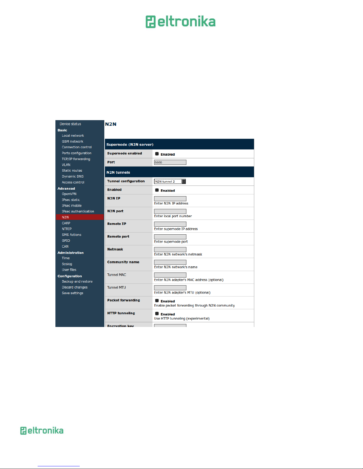
7.2.15 N2N
N2N is application that enables user to create secure subnetworks like OpenVPN
and IPsec, but it is based on P2P connections. User can configure modem to host N2N
server (just enable the option and choose port on which it will be available) and up to
four tunnels. To configure tunnel choose N2N IP address, local and remote port, netmask
and remote IP address. You have to input community name and key (all members of
N2N network should have same community name and key. Rest of parameters should be
used only by experienced users.
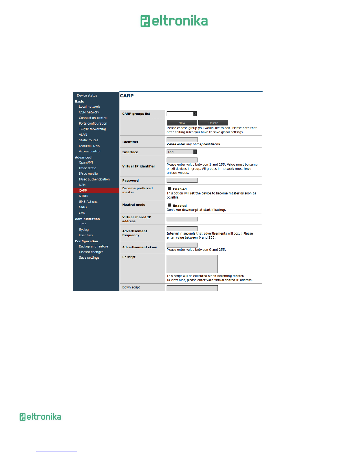
7.2.16 CARP
CARP is a network protocol that allows many devices to be connected into
redundancy group which will be available as one device on chosen network address. For
example you can choose devices that have IPs 192.168.1.2 and 192.168.1.3 to be
available on 192.168.1.115. If one device will stop working, the other one will serve
users at shared address. Device that is currently active on shared address is called
master and other devices are called backup.
Page 38
ELTRONIKA sp. z.o.o.
Ul. Warszawska 41 lok.7
05-092 Łomianki
[email protected]
www.eltronika.com
- Polska: +48 22 751 97 44
- Česká republika: +420 228 880 487
- Slovensko: +421 904 540 707
38
If you want to configure CARP, please choose network interface on which CARP
client will be available and choose group identifier that will be same on all devices in
group-it has to be number from 1 to 255. Enter virtual shared IP address. Advertisement
frequency and skew regulate how often devices will be contacting each other.
Remember to define up script and down script that will set/delete routings when
becoming master/backup.
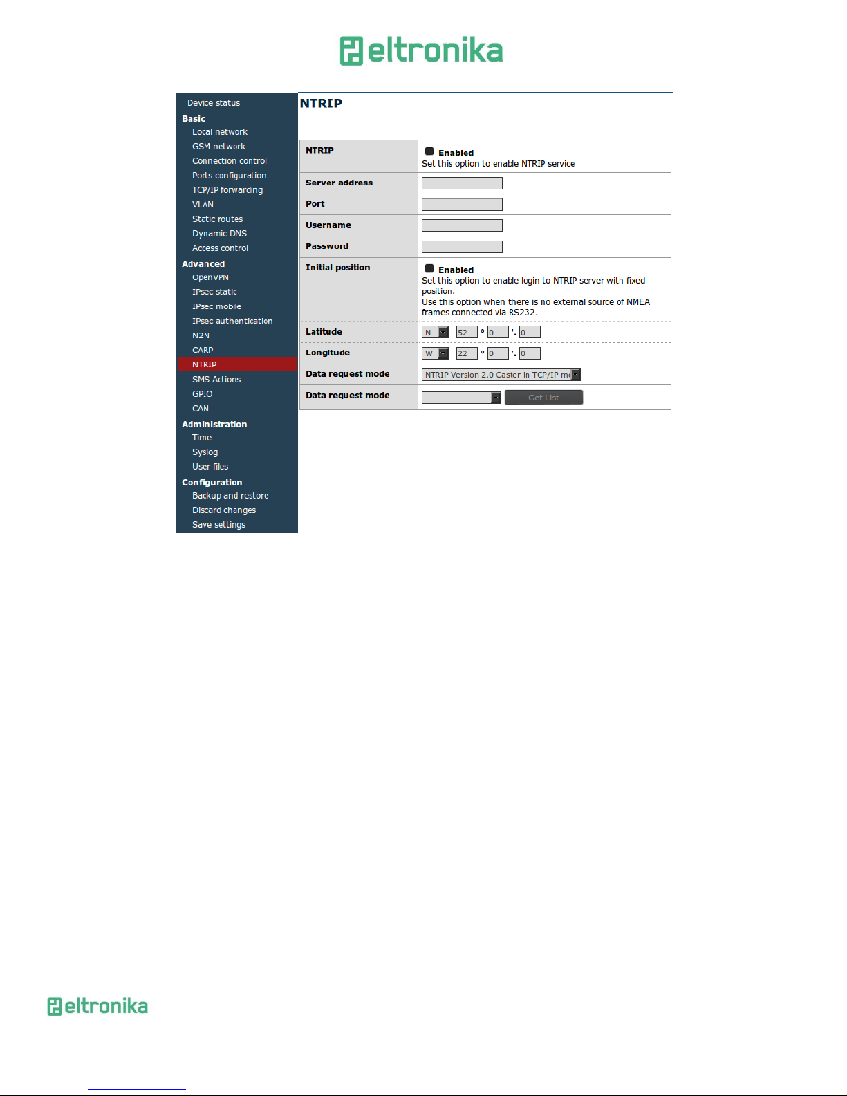
7.2.17 NTRIP configuration page
One of /dev/ttyS0 port modes is communication with external device using
NTRIP protocol. If you decide to use it, it is necessary to set the mode under RS232 Port
configuration page. Then, enter settings in NTRIP page. Server address, port and initial
position fields are necessary. Username and passwords are optional.
It is also possible to choose data request mode. After entering required data,
please click Get List button to download data streams list from the server – it may take a
while, please be patient. After downloading the list please select one of data streams.
Attention: Entering initial position is necessary to login to NTRIP server if no
external device sending NMEA frames is connected to the S0 port.
Page 39
ELTRONIKA sp. z.o.o.
Ul. Warszawska 41 lok.7
05-092 Łomianki
[email protected]
www.eltronika.com
- Polska: +48 22 751 97 44
- Česká republika: +420 228 880 487
- Slovensko: +421 904 540 707
39
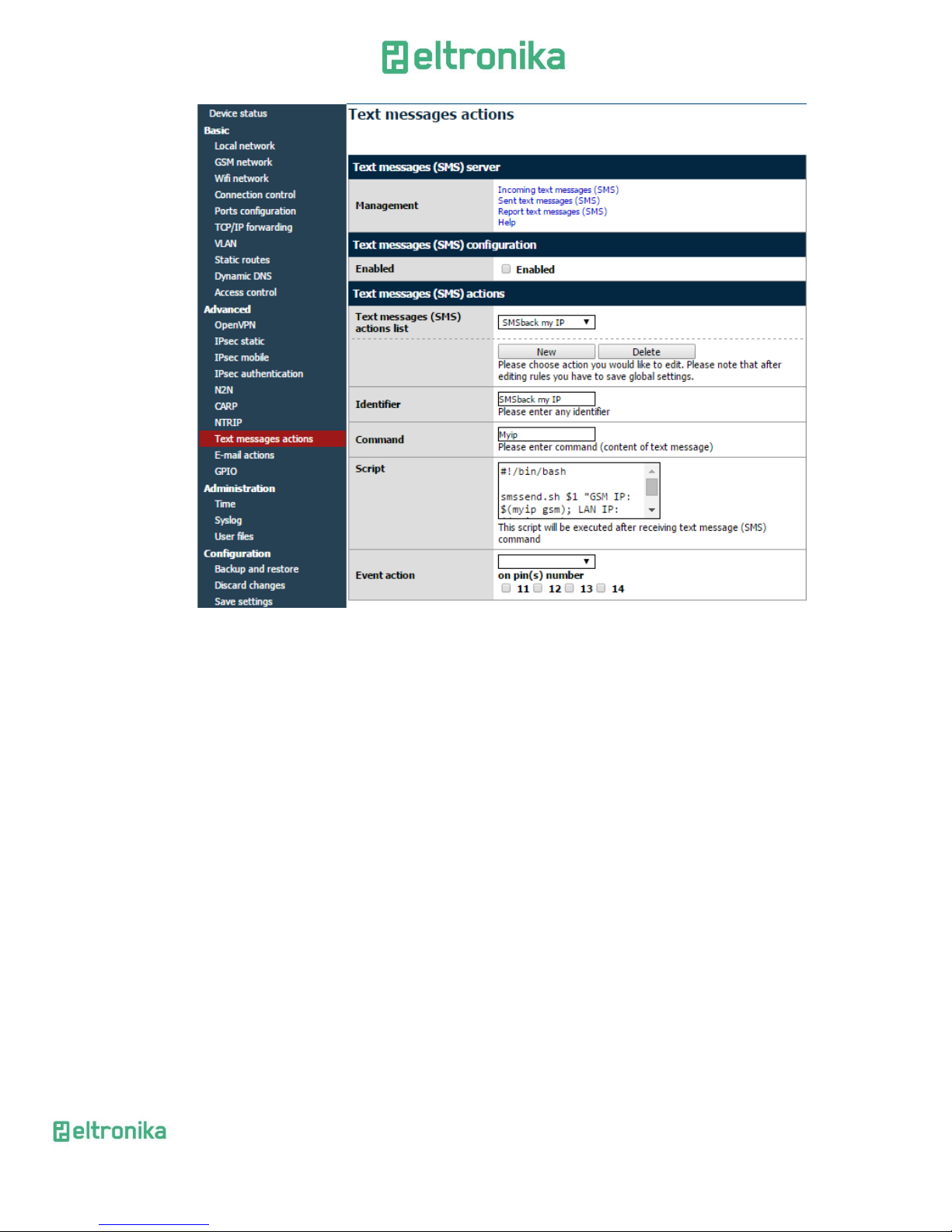
7.2.18 SMS Actions
SMS Actions tab allows user to define shell scripts that will be executed every
time modem receives SMS with specified content.
To enable this option ensure that global SMS Actions checkbox is enabled and you
have set one of available ports into SMS receiving mode under Ports configuration tab.
Then click New button, enter any identifier and command-sms content that will trigger
action. You can write any shell script you want and/or set GPIO action to be executed.
Page 40
ELTRONIKA sp. z.o.o.
Ul. Warszawska 41 lok.7
05-092 Łomianki
[email protected]
www.eltronika.com
- Polska: +48 22 751 97 44
- Česká republika: +420 228 880 487
- Slovensko: +421 904 540 707
40
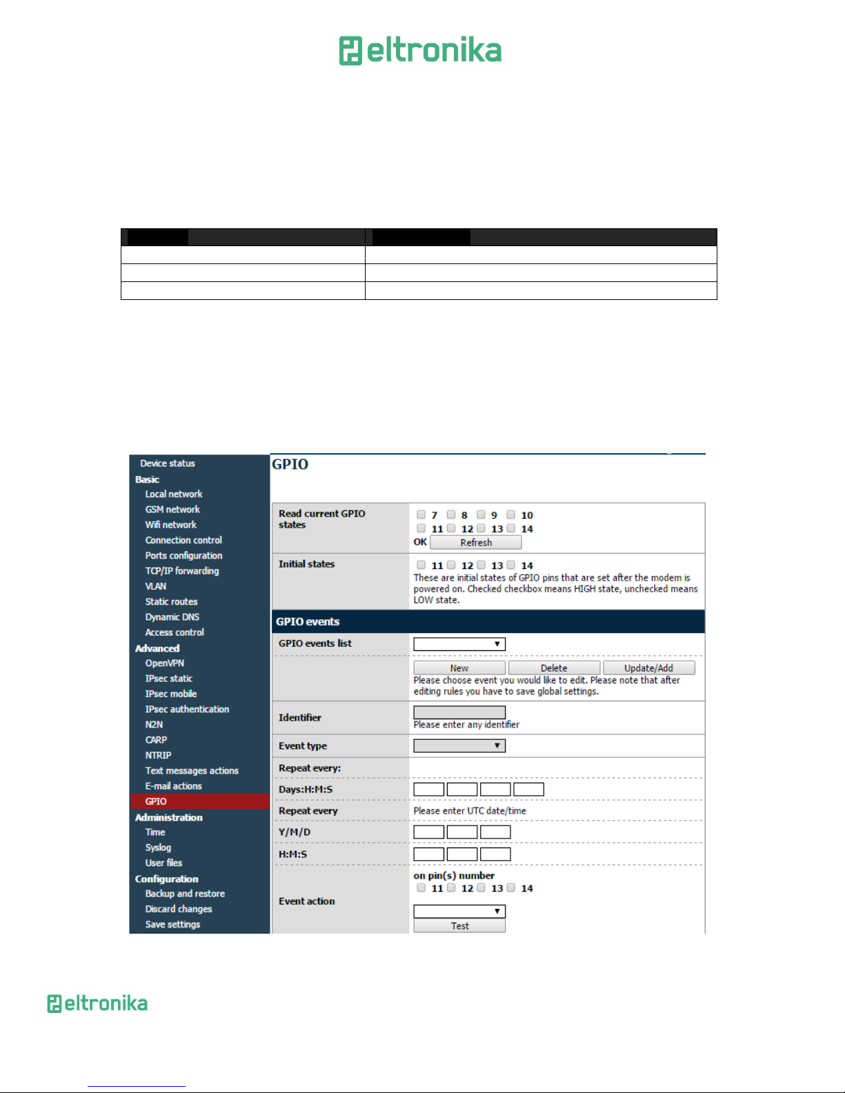
7.2.19 GPIO
Settings under GPIO tab in www configuration enable user to configure external
input and output GPIO ports. When switching tab to GPIO current pin states is read
automatically into eight fields in upper section of the webpage. In whole configuration
the following convention is used: the unchecked field represents low state and checked
field represents high state. Successful read of GPIO pins states is indicated by ,,OK''
status. In case of error ,,ERROR!'' is displayed. If pins state update is needed, please click
Refresh button.
To set initial states of output pins use checkboxes 11,12,13 and 14. They are set
when the modem is powered up and when the GPIO configuration is changed and saved.
Section GPIO events allows user to create unlimited number of events on which
the state of output pins will be changed. In order to create a new event, click New button
and then fill out all necessary fields. The identifier is used to distinguish events. It can be
any character string. The event type determines if an event is executed only once (One
time) or with determined frequency (Regular). In case of one time event enter UTC date
and time of the event. Make sure that real time clock is set correctly on the device. In
case of regular event specify time interval between two [consecutive] event executions.
Finally choose pin or pins used for the event and what action should be taken (setting
high state, setting low state or switching states). Let's assume pins 11,13 was selected
Page 41
ELTRONIKA sp. z.o.o.
Ul. Warszawska 41 lok.7
05-092 Łomianki
[email protected]
www.eltronika.com
- Polska: +48 22 751 97 44
- Česká republika: +420 228 880 487
- Slovensko: +421 904 540 707
41
and action set to ,,Set HIGH state''. As result at entered time of the event high state will
be set on pins 11,13 and on pins 12,14 no action will be taken (previous state will be
preserved). An event execution can be also directly tested by clicking Test (current GPIO
states will be refreshed automatically).
There is also a possibility to manually operate GPIO pins using HTTP GET
<device_ip>/actions/gpio_action.php request. The following parameters can be
used:
Parameter
Accepted values
cmd
readall, read, write
pins
Any combination of pins 7-14 separated by commas
state
H, L, I, S (high, low, input, switch states)
The readall command requires no additional parameters. However, read and
write requires setting pins parameter. write requires setting state parameter. Please
keep in mind that you are not able to set state on input pins. Parameters should be
provided in webpage address after ‘?’ character typical for complex GET requests.
Parameter and its values are separated with = character, i.e. ,,parameter=value'' . Each
pair of parameter and value are separated from another with & character (see
examples).
Page 42

ELTRONIKA sp. z.o.o.
Ul. Warszawska 41 lok.7
05-092 Łomianki
[email protected]
www.eltronika.com
- Polska: +48 22 751 97 44
- Česká republika: +420 228 880 487
- Slovensko: +421 904 540 707
42
Examples of usage are shown below.
Prints current state of all ports:
192.168.1.234/actions/gpio_action.php?cmd=readall
Prints current state of physical output number 14:
192.168.1.234/actions/gpio_action.php?cmd=read&pins=14
Sets low state on physical outputs number 11 and 12 (On successful execution no text is
printed):
192.168.1.234/actions/gpio_action.php?cmd=write&pins=11,12&state=L
Page 43
ELTRONIKA sp. z.o.o.
Ul. Warszawska 41 lok.7
05-092 Łomianki
[email protected]
www.eltronika.com
- Polska: +48 22 751 97 44
- Česká republika: +420 228 880 487
- Slovensko: +421 904 540 707
43
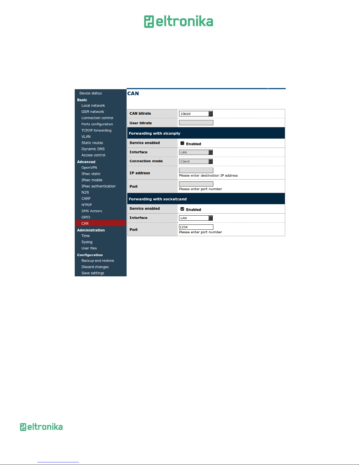
7.2.20 CAN
If you have modem with CAN interface you can configure it under CAN tab. You
can set the baudrate and set forwarding CAN frames to TCP using slcanpty or
socketcand.
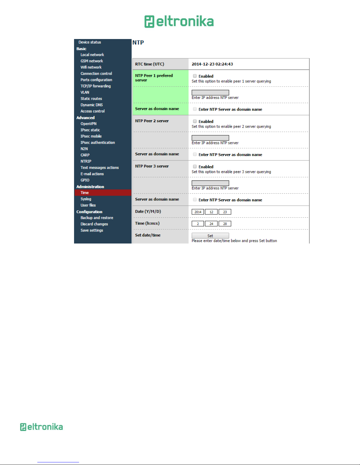
7.2.21 Time
Here you can manually set hardware clock or input IP of NTP server to
synchronize time automatically
Page 44
ELTRONIKA sp. z.o.o.
Ul. Warszawska 41 lok.7
05-092 Łomianki
[email protected]
www.eltronika.com
- Polska: +48 22 751 97 44
- Česká republika: +420 228 880 487
- Slovensko: +421 904 540 707
44
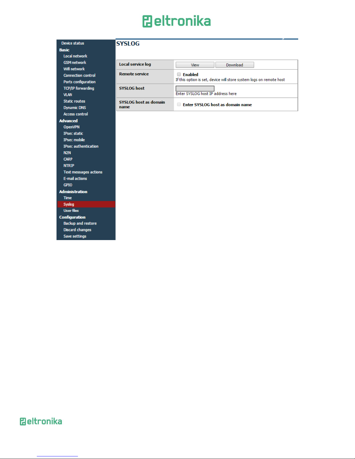
7.2.22 Syslog
Here you can define how modem should save your logs. Modem has internal
memory that get overwritten when it reaches its end. You can also save logs on your
computer by clicking download (manually). It is also possible to get remote access to
logs by enabling Remote service and setting SYSLOG host.
Page 45
ELTRONIKA sp. z.o.o.
Ul. Warszawska 41 lok.7
05-092 Łomianki
[email protected]
www.eltronika.com
- Polska: +48 22 751 97 44
- Česká republika: +420 228 880 487
- Slovensko: +421 904 540 707
45
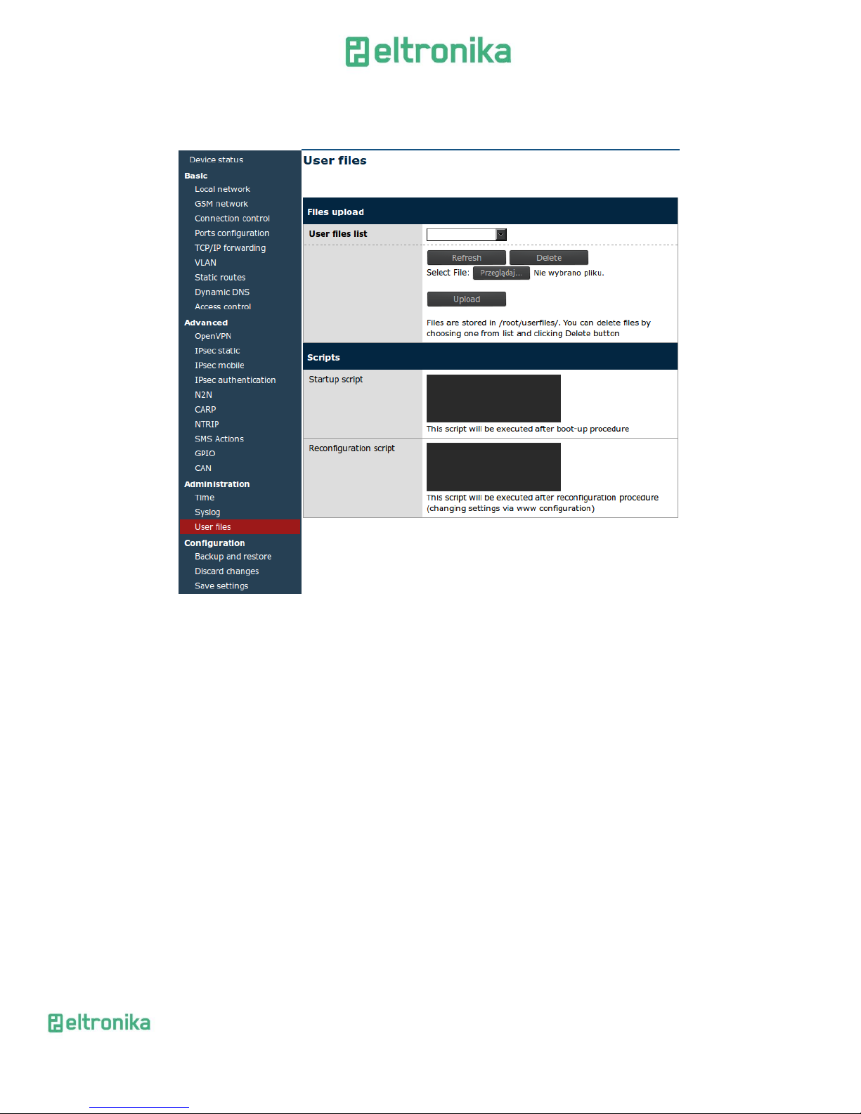
7.2.23 User files
You can upload to the modem your own scripts and executable files and set them
to be used in certain situations (e.x. when the VPN connection is established or at
modem startup). Under User files tab there is a list of user files. It is refreshed
automatically after selecting tab, it can be also manually refreshed by pressing Refresh
button. To delete file, select it from the list and press Delete button. To upload file, click
Upload new button. You will be redirected to separate site. Choose file by pressing
Browse... button and commit your choice by clicking Upload. After upload you will be
informed if the whole operation was successful or the error message will be displayed.
Use link to return to the main page of www configuration. All files are stored with rights
for file execution, so they can be used in scripts.
Below the file upload panel there are two fields, where you can write scripts.
Startup script will be executed after startup procedure of modem and Reconfiguration
script every time you click Save Configuration button in www configuration. You can
write your scripts in Bash or PHP, but remember to use special header for scripts
((#!/bin/bash lub #!/usr/bin/php). You can execute uploaded user files, they are stored
in /root/userfiles.
Page 46
ELTRONIKA sp. z.o.o.
Ul. Warszawska 41 lok.7
05-092 Łomianki
[email protected]
www.eltronika.com
- Polska: +48 22 751 97 44
- Česká republika: +420 228 880 487
- Slovensko: +421 904 540 707
46
WARNING: Binary files uploaded to modem should be compiled for processor
installed in modem!
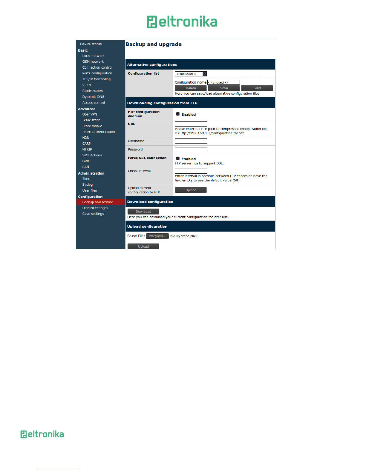
7.2.24 Backup and restore
Under backup and restore tab user can:
Save/load alternative configurations
Configure FTP client to periodically check FTP server for latest
configuration
Download/Upload backup configuration
Page 47
ELTRONIKA sp. z.o.o.
Ul. Warszawska 41 lok.7
05-092 Łomianki
[email protected]
www.eltronika.com
- Polska: +48 22 751 97 44
- Česká republika: +420 228 880 487
- Slovensko: +421 904 540 707
47
7.2.25 Discard changes
Discard current changes in configuration which were not saved yet.
7.2.26 Save settings
To save your settings click save setting and wait until message will show up to
confirm your configuration data was saved.
7.3 System logs description
This paragraph shows structure of typical System log with some basic errors:
01/01/0000:00:30 rbmtx syslogd 1.4.1: restart.
01/01/0000:00:31 rbmtx Start: RBMTX - FIRM:141226 – modem and firmware info
01/01/0000:00:35 rbmtx supervisor[560]: SIM Holder open/closed – SIM holder
open/closed by software
01/01/0000:00:36 rbmtx supervisor[560]: Modem init 1 – first initialization try
01/01/0000:01:09 rbmtx supervisor[560]: Init /dev/ttyS1 – port initialization
01/01/0000:01:10 rbmtx supervisor[560]: Init /dev/ttyACM0
Page 48

ELTRONIKA sp. z.o.o.
Ul. Warszawska 41 lok.7
05-092 Łomianki
[email protected]
www.eltronika.com
- Polska: +48 22 751 97 44
- Česká republika: +420 228 880 487
- Slovensko: +421 904 540 707
48
01/01/0000:01:13 rbmtx supervisor[560]: Modem is not registered on the GSM
network – modem is not able to log into network
01/01/0000:01:13 rbmtx supervisor[560]: Entering Modem is ready
01/01/0000:01:13 rbmtx supervisor[560]: Entering PIN OK – modem is ready for
connection
01/01/0000:01:13 rbmtx supervisor[560]: Entering PIN error code: - wrong PIN
message
01/01/0000:01:14 rbmtx login[811]: unable to change tty `/dev/ttyS0' for user `root'
01/01/0000:01:14 rbmtx login[811]: ROOT LOGIN on `ttyS0'
01/01/0000:01:20 rbmtx pppd[901]: pppd 2.4.5 started by root, uid 0 – connection
01/01/0000:01:21 rbmtx chat[903]: timeout set to 2 seconds
01/01/0000:01:21 rbmtx chat[903]: send (AT)
01/01/0000:01:21 rbmtx chat[903]: expect (OK)
01/01/0000:01:21 rbmtx chat[903]: AT
01/01/0000:01:21 rbmtx chat[903]: OK
01/01/0000:01:21 rbmtx chat[903]: send (ATZ0)
01/01/0000:01:21 rbmtx chat[903]: expect (OK)
01/01/0000:01:21 rbmtx chat[903]: ATZ0
01/01/0000:01:21 rbmtx chat[903]: OK
01/01/0000:01:21 rbmtx chat[903]: send (AT)
01/01/0000:01:21 rbmtx chat[903]: abort on (NO DIALTONE)
01/01/0000:01:21 rbmtx chat[903]: abort on (ERROR)
01/01/0000:01:21 rbmtx chat[903]: abort on (NO ANSWER)
01/01/0000:01:21 rbmtx chat[903]: abort on (BUSY)
01/01/0000:01:21 rbmtx chat[903]: expect (OK)
01/01/0000:01:21 rbmtx chat[903]: AT
01/01/0000:01:21 rbmtx chat[903]: OK
01/01/0000:01:21 rbmtx chat[903]: send (ATZ0)
01/01/0000:01:21 rbmtx chat[903]: abort on (NO CARRIER)
01/01/0000:01:21 rbmtx chat[903]: timeout set to 30 seconds
01/01/0000:01:21 rbmtx chat[903]: expect (OK)
01/01/0000:01:21 rbmtx chat[903]: ATZ0
01/01/0000:01:21 rbmtx chat[903]: OK
01/01/0000:01:21 rbmtx chat[903]: send (AT)
01/01/0000:01:21 rbmtx chat[903]: expect (OK)
01/01/0000:01:21 rbmtx chat[903]: AT
01/01/0000:01:21 rbmtx chat[903]: OK
01/01/0000:01:21 rbmtx chat[903]: send (AT+CGDCONT=1,"ip","example.apn")
01/01/0000:01:22 rbmtx chat[903]: clear abort on (ERROR)
01/01/0000:01:22 rbmtx chat[903]: send (dddATD*99#)
01/01/0000:01:23 rbmtx supervisor[560]: pppd check loop:1
01/01/0000:01:25 rbmtx chat[903]: expect (CONNECT)
01/01/0000:01:25 rbmtx chat[903]: AT+CGDCONT=1,"ip","example.apn"
Page 49

ELTRONIKA sp. z.o.o.
Ul. Warszawska 41 lok.7
05-092 Łomianki
[email protected]
www.eltronika.com
- Polska: +48 22 751 97 44
- Česká republika: +420 228 880 487
- Slovensko: +421 904 540 707
49
7.4 Firmware update
This chapter describes in few steps how to make upgrade of your modems
firmware. Actual number of your modems firmware can be found here:
http://x.x.x.x/firmware.php where x.x.x.x is ip adres of your modem (by default it is
192.168.1.234).
You need following files for upgrade and test your upgrade:
plink.exe (putty)
pscp.exe (putty)
service.key (private key)
servicekey.ppk (private key generated for putty)
upgrade.bat (upgrade scrypt)
upload_img.bat (copy .bin file to modem scrypt)
upgrade_20110301.bin (name depends on upgrade date)
Follow next steps to upgrade your firmware:
To start upgrade you need first to upload file upgrade_20110301.bat on your modem
to do this start file upload_img.bat with parameters: file and ip of modem.
upload_img.bat upgrade_20101001.bin 192.168.1.234
Can be done directly in Windows OS (remember about ‘:’ sign in the end)
pscp -scp -i servicekey.ppk -P 65535 [email protected]:
In Linux OS it should be similar:
scp -i service.key -P 65535 upgrade.bin service@IP:
You can start upgrade procedure by starting file
upgrade.bat 192.168.1.234
or on Windows OS:
plink -ssh -i servicekey.ppk -P 65535 [email protected] upgrade
and on Linux OS:
ssh -i service.key -p 65535 [email protected] upgrade
You can also use commands like reboot, delusblog, help, for example to reboot
system:
plink -ssh -i servicekey.ppk -P 65535 [email protected] reboot
Page 50
ELTRONIKA sp. z.o.o.
Ul. Warszawska 41 lok.7
05-092 Łomianki
[email protected]
www.eltronika.com
- Polska: +48 22 751 97 44
- Česká republika: +420 228 880 487
- Slovensko: +421 904 540 707
50
7.5 Eltronika Device Manager
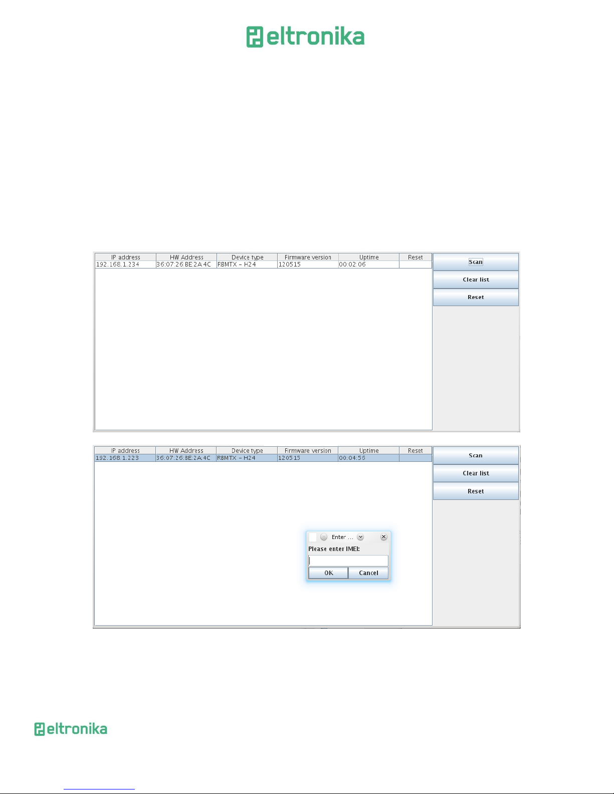
Eltronika Device Manager is an application which allows you to find ELT-LAN
modems in local area network (LAN) and then restore factory settings by entering their
IMEI number. It is particularly useful when you forgot IP number of device and you can't
access it by terminal on serial port.
The installation process is pretty simple-you launch .exe file and choose path
where to unpack the application. The main window of program consists of table-list of
devices available on your network and buttons: Scan, Clear List, Reset and About. First
you need to scan the network for devices. It takes few seconds to list all the devices.
Please also keep in mind that it takes a while to boot modem so it won't respond
immediately after you turn it on.
Page 51
ELTRONIKA sp. z.o.o.
Ul. Warszawska 41 lok.7
05-092 Łomianki
[email protected]
www.eltronika.com
- Polska: +48 22 751 97 44
- Česká republika: +420 228 880 487
- Slovensko: +421 904 540 707
51
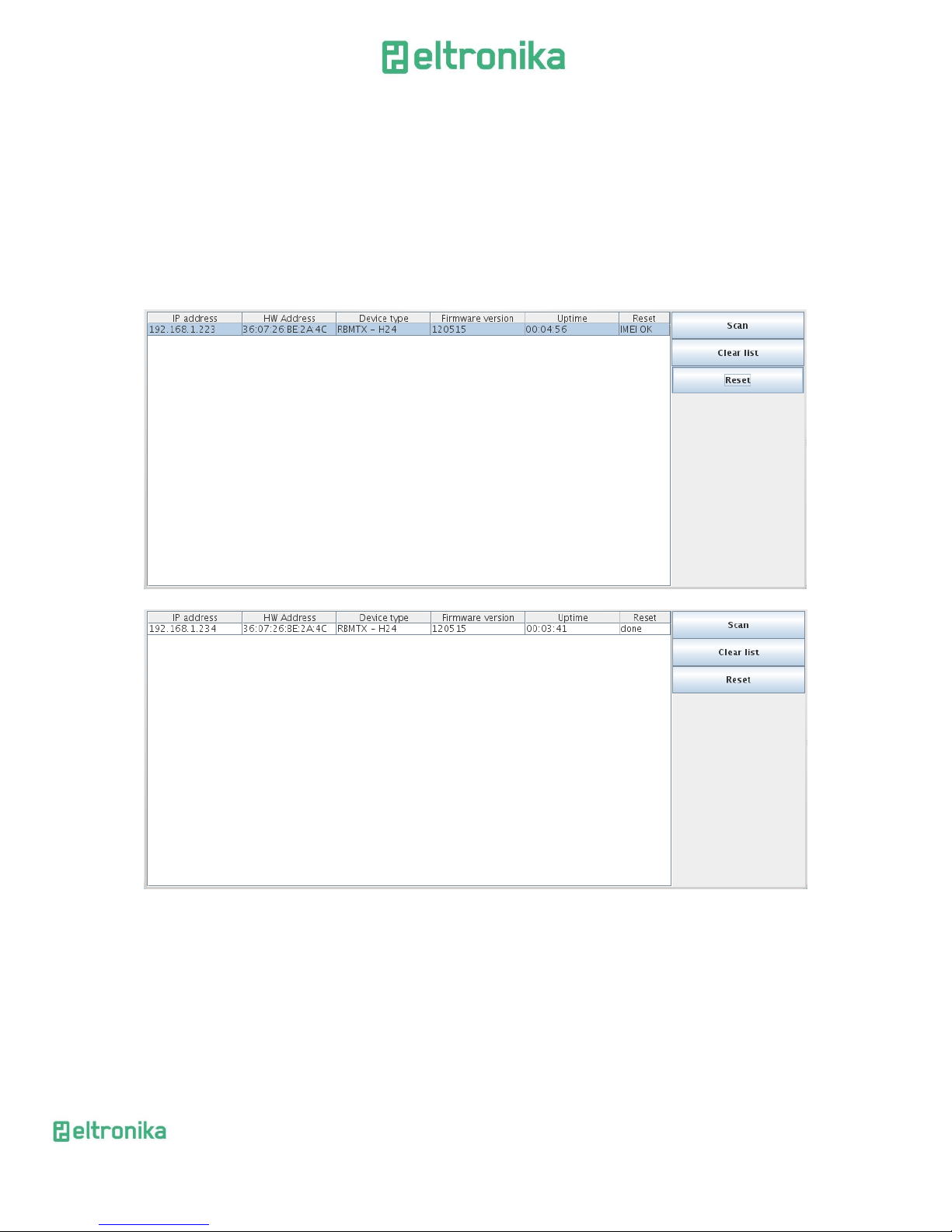
When the scan is complete you can see list of available devices in the table. You
can review information like IP address, MAC address, device name, firmware version
and uptime. If you want to restore factory settings on any device on the list, click the
Reset button and enter IMEI. Program will send special packet to all devices, but only the
one with IMEI you have entered will be affected. If the IMEI is correct and the factory
settings have been restored you should see ,,IMEI OK'' in one of cells of last column. This
device will now reset to load new settings and after about 1-2 minutes it will confirm
that whole operation was successful - you should see then that ,,IMEI OK'' will change to
,,done''.
Page 52

ELTRONIKA sp. z.o.o.
Ul. Warszawska 41 lok.7
05-092 Łomianki
[email protected]
www.eltronika.com
- Polska: +48 22 751 97 44
- Česká republika: +420 228 880 487
- Slovensko: +421 904 540 707
52
8 Troubleshooting
8.1 No communication with the modem
If there is no communication with the modem do the following steps:
Check all external connections of the modem
Verify if power supply is correct
Check if TCP/IP parameters are correct
Check if any firewall is not blocking connection with the modem
8.2 Modem answers but there is no internet connection
If there is no internet connection do following:
Check if antenna is connected properly
Check if you have reception of GPRS/EDGE/HSPA signal in your area (on
website of GSM provider
Check if you configured your modem with proper parameters provided by
your network provider (they should match in order to connect to internet)
In case you do not have internet access contact your provider in order to
get internet access
Page 53
ELTRONIKA sp. z.o.o.
Ul. Warszawska 41 lok.7
05-092 Łomianki
[email protected]
www.eltronika.com
- Polska: +48 22 751 97 44
- Česká republika: +420 228 880 487
- Slovensko: +421 904 540 707
53
9 Technical characteristics
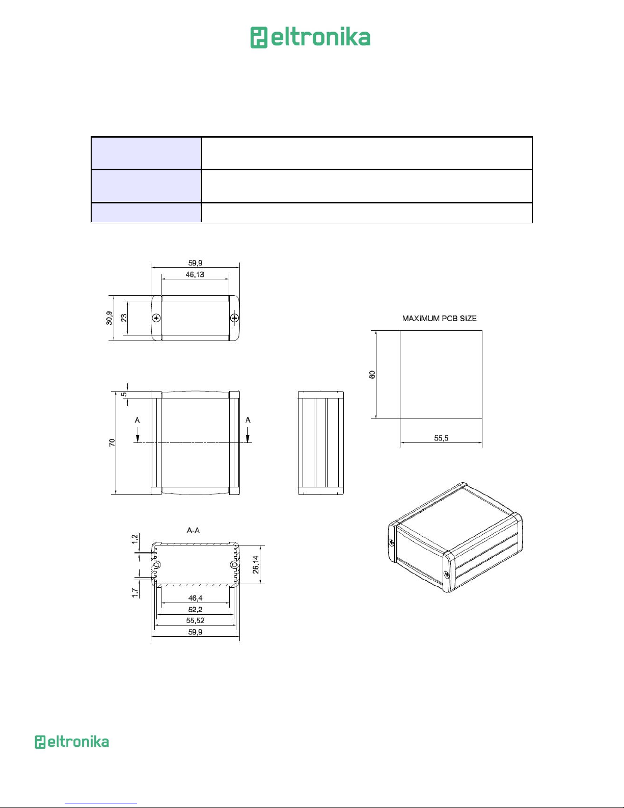
9.1 Mechanical characteristic
Max. dimensions
70 x 59,9 x 30,9 mm (w/o connectors)
80 x 59,9 x 30,9 mm (w/ connectors)
Weight
≈138,3 g (only modem w/o any external connection)
≈145,7g (modem w/ antenna)
Volume
≈129,56 cm3 (w/o connectors)
9.2 Housing (dimension diagram)
Page 54
ELTRONIKA sp. z.o.o.
Ul. Warszawska 41 lok.7
05-092 Łomianki
[email protected]
www.eltronika.com
- Polska: +48 22 751 97 44
- Česká republika: +420 228 880 487
- Slovensko: +421 904 540 707
54
9.3 Electrical characteristic
9.3.1 Power supply
Nominal voltage range: 6V..30V
Maximum continuous supply power: 5W
Peak (momentary) supply current: 2 A
9.3.2 RF characteristics
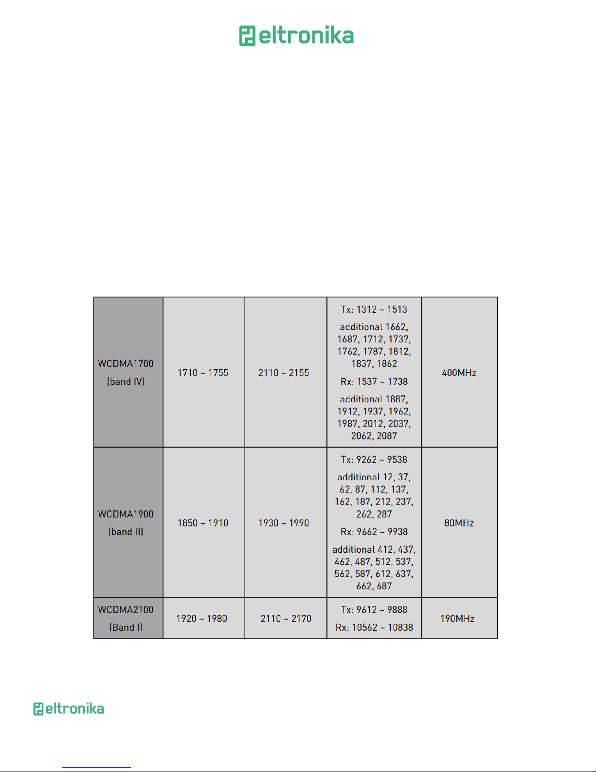
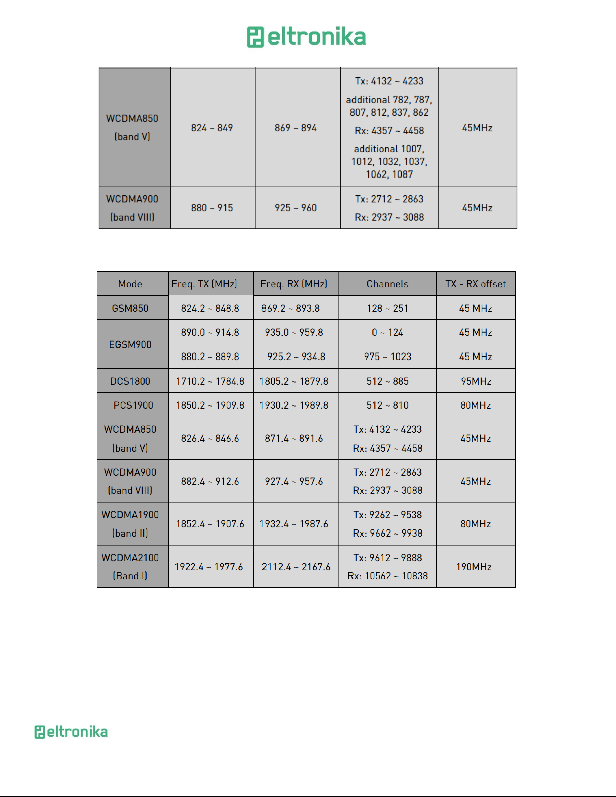
9.3.2.1 Frequency ranges
Range depends on the module that is used in your version of device and type of
network you choose to use.
HSPA+ variant :
Page 55
ELTRONIKA sp. z.o.o.
Ul. Warszawska 41 lok.7
05-092 Łomianki
[email protected]
www.eltronika.com
- Polska: +48 22 751 97 44
- Česká republika: +420 228 880 487
- Slovensko: +421 904 540 707
55
UMTS variant :
Page 56
ELTRONIKA sp. z.o.o.
Ul. Warszawska 41 lok.7
05-092 Łomianki
[email protected]
www.eltronika.com
- Polska: +48 22 751 97 44
- Česká republika: +420 228 880 487
- Slovensko: +421 904 540 707
56
9.3.2.2 WiFi characteristics :
Standards
802.11b/g/n, 802.3, 802.3u
Frequency band
2.4 Ghz
Output power
13 dBm@11n
17 dBm@11b
15 dBm@11g
tolerance ±2 dBm.
Data rates:
up to 150Mbps
9.3.2.3 External antenna
The external antenna is connected to the modem via SMA connector.
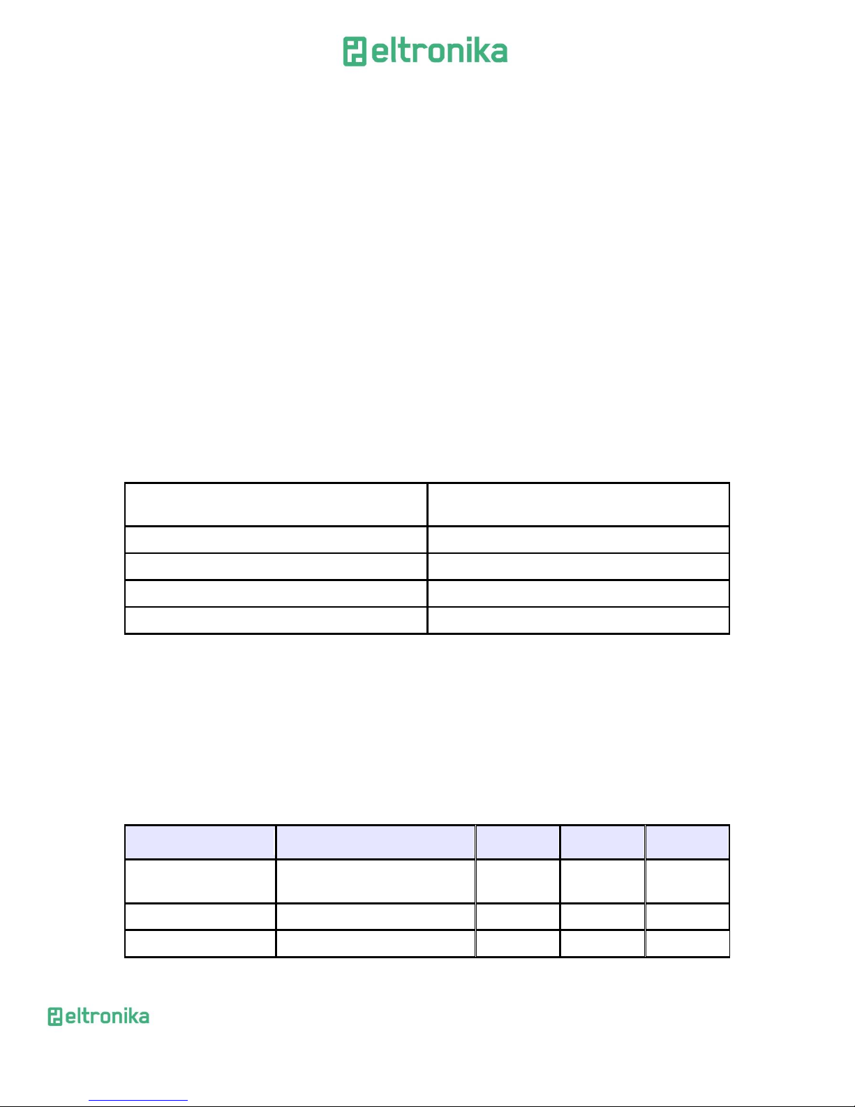
Antenna must have parameters as shown below in table.
Antenna frequency range
Supporting GSM, UMTS or LTE frequencies for
GSM or ISM 2.4 GHz for WIFI
Impedance
50 Ω
DC impedance
0 Ω
Gain
0 dBi w/o cable; 2dBi w/ cable
VSWR (with cable)
-10 dB
The antenna chosen for working with modem should best fit to circumstances of
environment it is used in. When the modem is placed in a room or somewhere where the
range of networks signal is too low, the outdoor or specific indoor antenna should be
used to increase it.
9.4 Environmental characteristic
Table below gives the environmental operating conditions of the inside module.
Attention! Exceeding the values may result in permanent damage to the module.
Parameter
Conditions
Min
Max
Unit
Ambient Operating
Temperature
-20
60
°C
Storage Temperature
-40
85
°C
Page 57
ELTRONIKA sp. z.o.o.
Ul. Warszawska 41 lok.7
05-092 Łomianki
[email protected]
www.eltronika.com
- Polska: +48 22 751 97 44
- Česká republika: +420 228 880 487
- Slovensko: +421 904 540 707
57
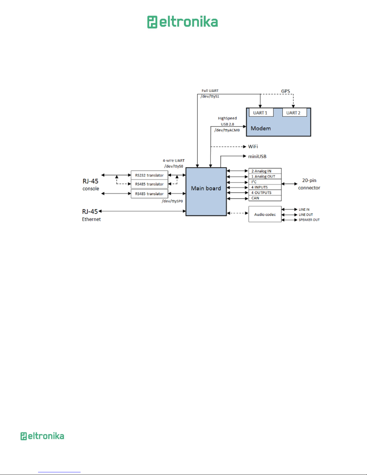
10 Terminal architecture
Diagram below shows simplified architecture of ELT-LAN. Features marked with
dotted lines are available as option.
Page 58

ELTRONIKA sp. z.o.o.
Ul. Warszawska 41 lok.7
05-092 Łomianki
[email protected]
www.eltronika.com
- Polska: +48 22 751 97 44
- Česká republika: +420 228 880 487
- Slovensko: +421 904 540 707
58
11 Safety recommendations
11.1 General Safety
Please follow safety regulations regarding the use of radio equipment due to the
possibility of radio frequency interference. Read given advices carefully.
Switch off GSM terminal when:
in an aircraft – using cellular telephones in aircraft may endanger the
operation of the aircraft; it is illegal
at a refuelling point
in any area with potentially explosive atmosphere which could cause an
explosion or fire
in hospitals and any other places where medical equipment is in use
Respect restrictions on the use of radio equipment in any area or place where it is
signalized that using cellular telephony is forbidden or dangerous.
Using GSM modem close to other electronic equipment may also cause
interference if the equipment is inadequately protected. It may lead to damage or failure
of GSM modem or the other equipment.
Page 59

ELTRONIKA sp. z.o.o.
Ul. Warszawska 41 lok.7
05-092 Łomianki
[email protected]
www.eltronika.com
- Polska: +48 22 751 97 44
- Česká republika: +420 228 880 487
- Slovensko: +421 904 540 707
59
11.2 Care and Maintenance
The ELT-LAN terminal is an electronic product that should be treated with care.
Please follow suggestions shown below due to using modem for many years.
Do not expose terminal to any extreme circumstances like high
temperature or high humidity
Do not keep modem in dirty and dust places
Do not disassemble the modem
Do not expose the modem to any water, rain or steam
Do not drop, shake or knocking your modem
Do not place your modem close to magnetic devices – credit cards, etc
Use of third party equipment or accessories, not made or authorized by
Eltronika Electronics may invalid the warranty of modem and/or cause
failure or permanent damage of modem
Do not expose the modem to children under 3 years
11.3 Responsibility
The modem is under your responsibility. Please treat it with care, and respect
local regulations. This is not a toy – keep it out of the reach of children.
Try to use security features (PIN etc.) to block unauthorized use or theft.
Page 60
ELTRONIKA sp. z.o.o.
Ul. Warszawska 41 lok.7
05-092 Łomianki
[email protected]
www.eltronika.com
- Polska: +48 22 751 97 44
- Česká republika: +420 228 880 487
- Slovensko: +421 904 540 707
60
12 Accessories
The tables below shows recommended accessories for ELT-LAN terminal.
12.1 Accessories critical for using modem
Table below shows accessories critical for using modem. Without them usage of
modem is impossible.
Accessory
Description
Part no.
Power adaptor
6V … 30V
PS6V1500MA
Antenna
-
ANTDBSMRSMA
12.2 Additional accessories
Table below shows additional accessories that are not essential for modem usage,
but can be useful or needed.
Accessory
Description
Part no.
Directional antenna (1)
Directional antenna for GSM900
AK 5GSM/X
Directional antenna (2)
Directional antenna for GSM1900
AK 7/DCS-UMTS/10
Omnidirectional antenna (1)
Omnidirectional antenna
AK PN
Omnidirectional antenna (2)
Omnidirectional antenna
AK C1
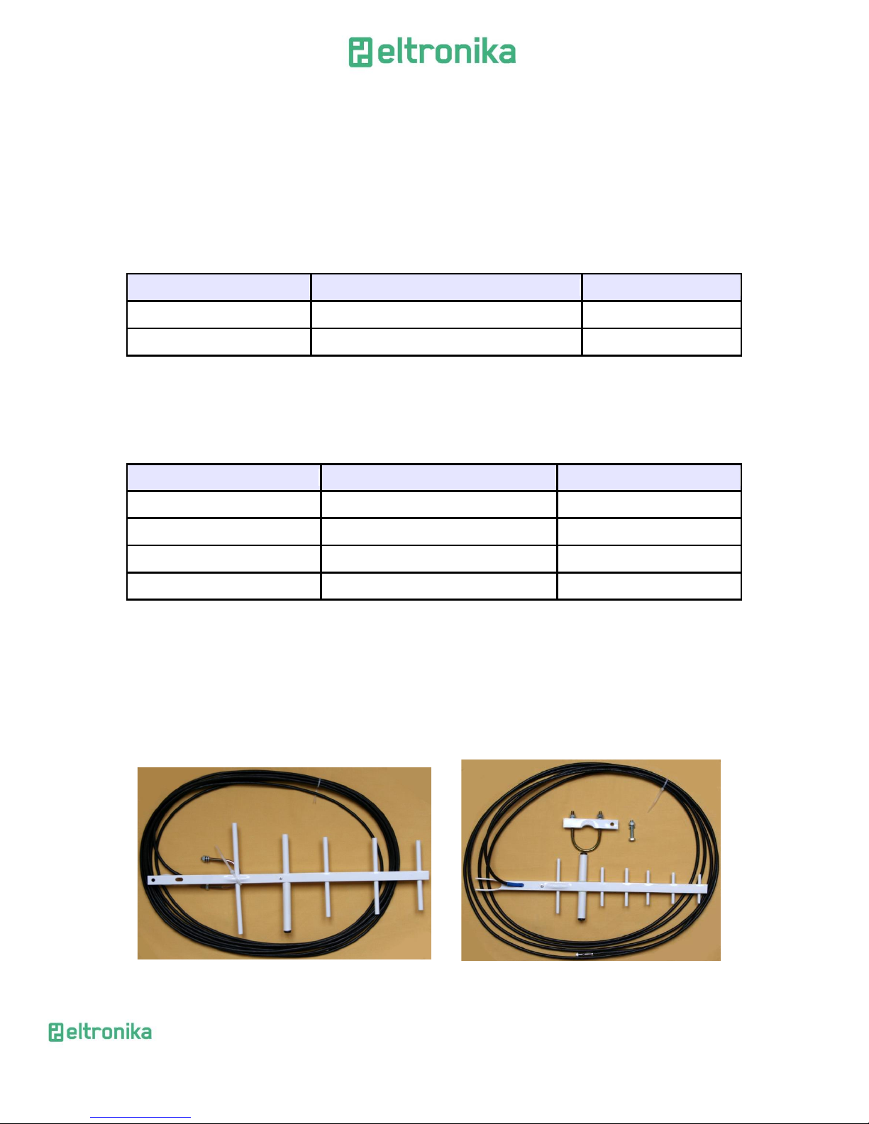
12.2.1 Directional antennas
Use directional (outdoor or indoor) antennas if signal range is too low or very
low. Directional antenna can increase signal level. Using the antenna cannot guarantee
sufficient range of signal – it depends on GSM coverage in place where modem is used. It
is better to use an antenna which works in higher frequency (GSM1900), but it depends
on if GSM1900 signal is transmitted in area of use – if not use antenna for lower
frequency (GSM900). If there is no GSM signal any antenna would help.
Directional antenna AK 5GSM/X Directional antenna AK 7/DCS-UMTS/10
Page 61
ELTRONIKA sp. z.o.o.
Ul. Warszawska 41 lok.7
05-092 Łomianki
[email protected]
www.eltronika.com
- Polska: +48 22 751 97 44
- Česká republika: +420 228 880 487
- Slovensko: +421 904 540 707
61
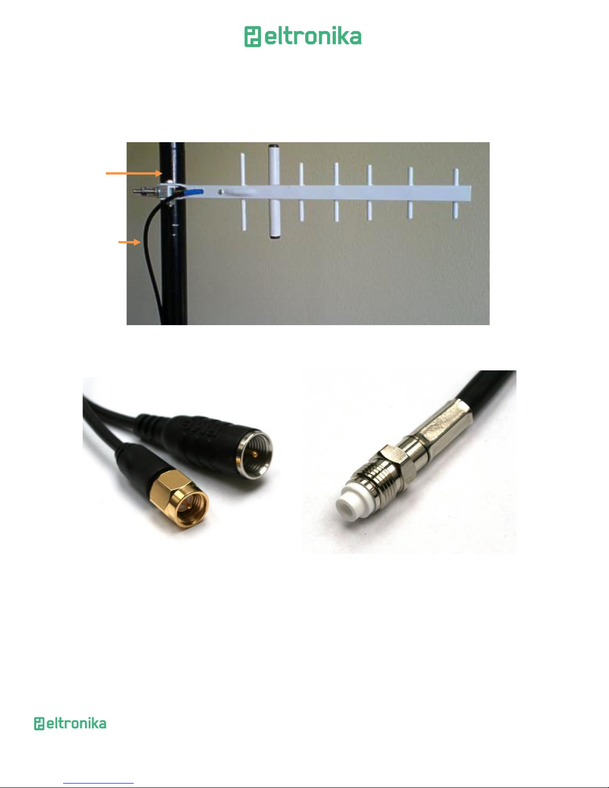
It is possible that there is no signal in buildings – the antenna in that cases can be mounted
on the roof or in a room where signal is sufficient. The antenna can be mounted on an aerial
mast (as shown in pictures below) or in other ways. All instructions of mounting an antenna
should be given by antenna producer.
If directional antenna is connected by FME connector (shown in picture) You can
use FME – SMA converter:
FME – SMA converter FMA connector male
Aerial
mast
Cable is
connected
to modem
Page 62
ELTRONIKA sp. z.o.o.
Ul. Warszawska 41 lok.7
05-092 Łomianki
[email protected]
www.eltronika.com
- Polska: +48 22 751 97 44
- Česká republika: +420 228 880 487
- Slovensko: +421 904 540 707
62
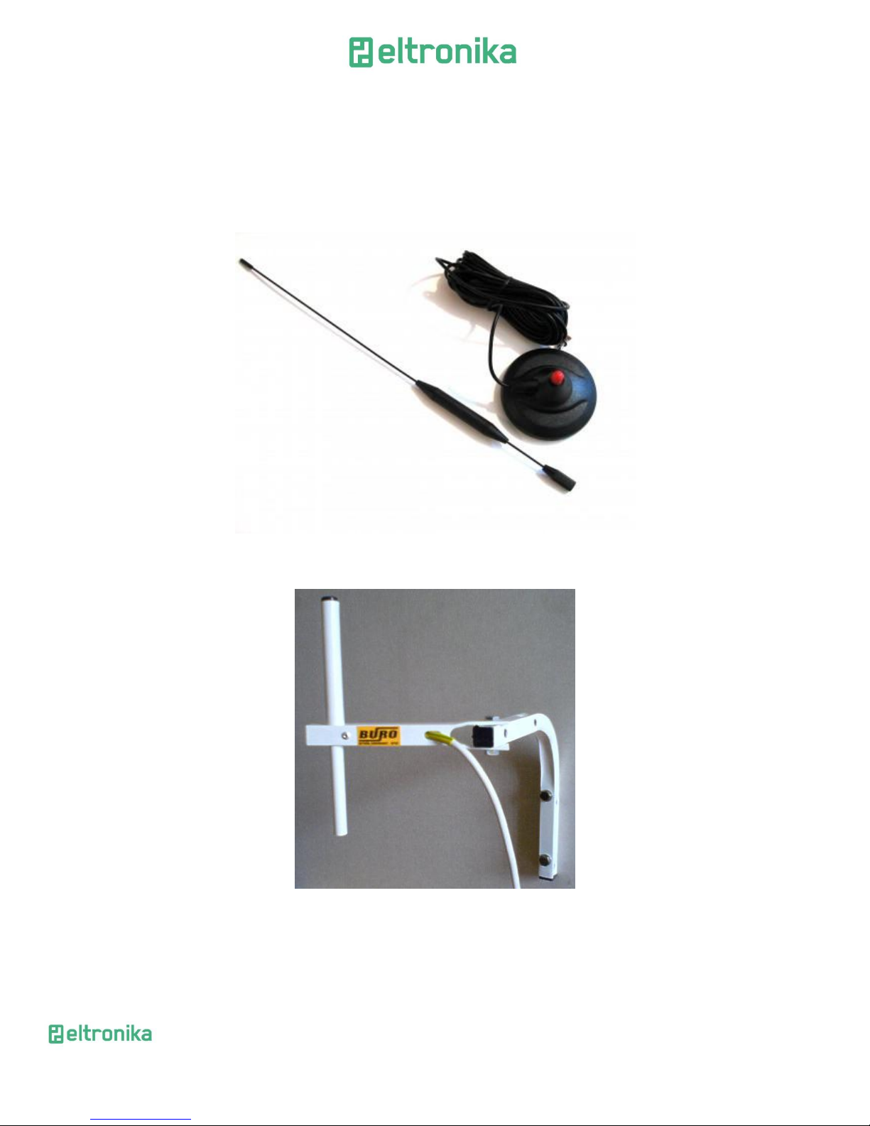
12.2.2 Omnidirectional antennas
In case of weak coverage you can also use omnidirectional antennas. The signal
gain of omnidirectional antenna is lower than directional antenna. Still, in most cases
this is enough to get proper reception. You can use magnetic base or wall handle
antennas, they differ in way of mounting – see pictures below.
AK PN antenna with magnetic base
AK C1 antenna with wall handle
Page 63

ELTRONIKA sp. z.o.o.
Ul. Warszawska 41 lok.7
05-092 Łomianki
[email protected]
www.eltronika.com
- Polska: +48 22 751 97 44
- Česká republika: +420 228 880 487
- Slovensko: +421 904 540 707
63
13 On-line support
Eltronika provides a range on on-line support which includes:
the latest version of this document
the latest drivers for ELT-LAN
technical support
This information can be found on our web sites at:
www.eltronika.com .
For further information You can contact us at:
email: [email protected]
Technical support:
Tel. +48 22 751 9744
Email: [email protected]
READ CAREFULLY
Be sure the use of this product is allowed in the country and in the
environment required. The use of this product may be dangerous and has to be avoided
in the following areas:
• Where it can interfere with other electronic devices in
environments such as hospitals, airports, aircrafts, etc
• Where there is risk of explosion such as gasoline stations,
oil refineries, etc
It is responsibility of the user to enforce the country regulation and the
specific environment regulation.
Page 64

ELTRONIKA sp. z.o.o.
Ul. Warszawska 41 lok.7
05-092 Łomianki
[email protected]
www.eltronika.com
- Polska: +48 22 751 97 44
- Česká republika: +420 228 880 487
- Slovensko: +421 904 540 707
64
Do not disassemble the product; any mark of tampering will compromise
the warranty validity.
We recommend following the instructions of the hardware user guides for
a correct wiring of the product. The product has to be supplied with a stabilized voltage
source and the wiring has to be conforming to the security and fire prevention
regulations.
The product has to be handled with care, avoiding any contact with the
pins because electrostatic discharges may damage the product itself. The same cautions
have to be taken for the SIM, checking carefully the instruction for its use. Do not insert
or remove the SIM when the product is in power saving mode.
The system integrator is responsible of the functioning of the final
product; therefore, care has to be taken to the external components of the module, as
well as of any project or installation issue, because the risk of disturbing the GSM
network or external devices or having impact on the security. Should there be any doubt,
please refer to the technical documentation and the regulations in force.
Every module has to be equipped with a proper antenna with specific
characteristics. The antenna has to be installed with care in order to avoid any
interference with other electronic devices and has to guarantee a minimum distance
from the people (20 cm). In case of this requirement cannot be satisfied, the system
integrator has to assess the final product against the SAR regulation.
1. The unit does not provide protection from lightning and surge. For outdoor
installation use outdoor nonmetallic case safety approved according UL 50. Additionally
you should provide protection from lightning and over voltage according National code.
2. Be sure the use of this product is allowed in the country and in the
environment required. The use of this product may be dangerous and has to be avoided
in the following areas: Where it can interfere with other electronic devices in
environments such as hospitals, airports, aircrafts, etc. Where there is risk of explosion
such as gasoline stations, oil refineries, etc. It is responsibility of the user to enforce the
country regulation and the specific environment regulation. Do not disassemble the
product; any mark of tampering will compromise the warranty validity. We recommend
following the instructions of the hardware user guides for a correct wiring of the
product. The product has to be supplied with a stabilized voltage source and the wiring
has to be conforming to the security and fire prevention regulations. The product has to
be handled with care, avoiding any contact with the pins because electrostatic
discharges may damage the product itself. Same cautions have to be taken for the SIM,
checking carefully the instruction for its use. Do not insert or remove the SIM when the
product is in power saving mode. The system integrator is responsible of the functioning
of the final product; therefore, care has to be given to the external components of the
unit, as well as of any project or installation issue, because the risk of disturbing the GSM
network or external devices or having impact on the security. Should there be any doubt,
please refer to the technical documentation and the regulations in force. Every unit has
Page 65

ELTRONIKA sp. z.o.o.
Ul. Warszawska 41 lok.7
05-092 Łomianki
[email protected]
www.eltronika.com
- Polska: +48 22 751 97 44
- Česká republika: +420 228 880 487
- Slovensko: +421 904 540 707
65
to be equipped with a proper antenna with specific characteristics. The antenna has to
be installed with care in order to avoid any interference with other electronic devices
and has to guarantee a minimum distance from the body (20 cm/8”). In case this
requirement cannot be satisfied, the system integrator should assess the final product
against the SAR regulation. The European Community provides some Directives for the
electronic equipment introduced on the market. All the relevant information available
on the European Community website:
http://europa.eu.int/comm/enterprise/rtte/dir99-5.htm
The text of the Directive 99/05 regarding telecommunication equipment is
available, while the applicable Directives (Low Voltage and EMC) are available at:
http://europa.eu.int/comm/enterprise/electr_equipment/index_en.htm
Page 66
ELTRONIKA sp. z.o.o.
Ul. Warszawska 41 lok.7
05-092 Łomianki
[email protected]
www.eltronika.com
- Polska: +48 22 751 97 44
- Česká republika: +420 228 880 487
- Slovensko: +421 904 540 707
66
14 Certifications
14.1 Conformity Assessment Issues
The ELT-LAN has been assessed in order to satisfy the essential requirements
of the R&TTE Directive 1999/05/EC (Radio Equipment & Telecommunications
Terminal Equipments) to demonstrate the conformity against the harmonised
standards with the final involvement of a Notified Body.
14.2 Declatarions of conformity
The ELT-LAN product is in conformity with the following
standards or other normative documents:
Name: Industrial GSM/UMTS router
Model: ELT-LAN-Ux1
Name: Industrial GSM/UMTS router
with WiFi
Model: ELT-LAN-Ux1.X.W.X.X
R&TTE 1999/5/EC
RF spectrum use (R&TTE art. 3.2):
EN 301 511 V9.02
EN 301 908-1 V5.2.1
EN 301 908-2 V5.2.1
EMC (R&TTE art. 3.1b):
EN 301 489-1 V1.9.2
EN 301 489-7 V1.3.1
EN 301 489-24 V1.5.1
EN 55022
Health & Safety (R&TTE art. 3.1a):
EN 60950-1
Reference standard(s):
R&TTE 1999/5/EC
RF spectrum use (R&TTE art. 3.2):
EN 301 511 V9.02
EN 301 908-1 V5.2.1
EN 301 908-2 V5.2.1
EN 300 328
EN 301 489-3
EMC (R&TTE art. 3.1b):
EN 301 489-1 V1.9.2
EN 301 489-7 V1.3.1
EN 301 489-24 V1.5.1
EN 55022
Health & Safety (R&TTE art. 3.1a):
EN 60950-1
Page 67
ELTRONIKA sp. z.o.o.
Ul. Warszawska 41 lok.7
05-092 Łomianki
[email protected]
www.eltronika.com
- Polska: +48 22 751 97 44
- Česká republika: +420 228 880 487
- Slovensko: +421 904 540 707
67
Name: Industrial
GSM/UMTS/HSPA+router
Model: ELT-LAN-Hx1
Name: Industrial GSM/UMTS/HSPA
router with WiFi
Model: ELT-LAN-Hx1.X.W.X.X
R&TTE 1999/5/EC
RF spectrum use (R&TTE art. 3.2):
EN 301 511 V9.02
EN 301 908-1 V5.2.1
EN 301 908-2 V5.2.1
EMC (R&TTE art. 3.1b):
EN 301 489-1 V1.9.2
EN 301 489-7 V1.3.1
EN 301 489-24 V1.5.1
EN 55022
Health & Safety (R&TTE art. 3.1a):
EN 60950-1
R&TTE 1999/5/EC
RF spectrum use (R&TTE art. 3.2):
EN 301 511 V9.02
EN 301 908-1 V5.2.1
EN 301 908-2 V5.2.1
EN 300 328
EN 301489-3
EMC (R&TTE art. 3.1b):
EN 301 489-1 V1.9.2
EN 301 489-7 V1.3.1
EN 301 489-24 V1.5.1
EN 55022
Health & Safety (R&TTE art. 3.1a):
EN 60950-1
Page 68
ELTRONIKA sp. z.o.o.
Ul. Warszawska 41 lok.7
05-092 Łomianki
[email protected]
www.eltronika.com
- Polska: +48 22 751 97 44
- Česká republika: +420 228 880 487
- Slovensko: +421 904 540 707
68
Name: Industrial
GSM/UMTS/HSPA+/LTE router
Model: ELT-LAN-Lx1
Name: Industrial
GSM/UMTS/HSPA+/LTE router
with WiFi
Model: ELT-LAN-Lx1.X.W.X.X
R&TTE 1999/5/EC
RF spectrum use (R&TTE art. 3.2):
EN300 440-2 V1.4.1
EN 301 511 V9.02
EN 301 908-1 V6.2.1
EN 301 908-2 V5.4.1
EN 301 908-13 V5.2.1
EMC (R&TTE art. 3.1b):
EN 301 489-1 V1.9.2
EN 301 489-3 V1.6.1
EN 301 489-7 V1.3.1
EN 301 489-24 V1.5.1
EN 55022 Class B
Health & Safety (R&TTE art. 3.1a):
EN 60950-1
R&TTE 1999/5/EC
RF spectrum use (R&TTE art. 3.2):
EN 300 440-2 V1.4.1
EN 301 511 V9.02
EN 301 908-1 V6.2.1
EN 301 908-2 V5.4.1
EN 301 908-13 V5.2.1
EN 300 328
EN 301 489-3
EMC (R&TTE art. 3.1b):
EN 301 489-1 V1.9.2
EN 301 489-3 V1.6.1
EN 301 489-7 V1.3.1
EN 301 489-24 V1.5.1
EN 55022 Class B
Health & Safety (R&TTE art. 3.1a):
EN 60950-1
14.3 National restrictions
This device is intended for use in all EU countries (and other
countries following the EU directive 1999/5/EC) without any
limitation except for the countries mentioned below:
Norway
This subsection does not apply for the geographical area within a radius of 20 km
from the centre of Ny-Ålesund
Page 69
ELTRONIKA sp. z.o.o.
Ul. Warszawska 41 lok.7
05-092 Łomianki
[email protected]
www.eltronika.com
- Polska: +48 22 751 97 44
- Česká republika: +420 228 880 487
- Slovensko: +421 904 540 707
69
15 List of Acronyms
ACM
Accumulated Call Meter
ASCII
American Standard Code for Information Interchange
AT
Attention commands
CB
Cell Broadcast
CBS
Cell Broadcasting Service
CCM
Call Control Meter
CLIP
Calling Line Identification Presentation
CLIR
Calling Line Identification Restriction
CMOS
Complementary Metal-Oxide Semiconductor
CR
Carriage Return
CSD
Circuit Switched Data
CTS
Clear To Send
DAI
Digital Audio Interface
DCD
Data Carrier Detected
DCE
Data Communications Equipment
DRX
Data Receive
DSR
Data Set Ready
DTA
Data Terminal Adaptor
DTE
Data Terminal Equipment
DTMF
Dual Tone Multi Frequency
DTR
Data Terminal Ready
EMC
Electromagnetic Compatibility
ETSI
European Telecommunications Equipment Institute
FTA
Full Type Approval (ETSI)
GPRS
General Radio Packet Service
GSM
Global System for Mobile communication
HF
Hands Free
IMEI
International Mobile Equipment Identity
IMSI
International Mobile Subscriber Identity
IRA
Internationale Reference Alphabet
ITU
International Telecommunications Union
IWF
Inter-Working Function
LCD
Liquid Crystal Display
LED
Light Emitting Diode
Page 70
ELTRONIKA sp. z.o.o.
Ul. Warszawska 41 lok.7
05-092 Łomianki
[email protected]
www.eltronika.com
- Polska: +48 22 751 97 44
- Česká republika: +420 228 880 487
- Slovensko: +421 904 540 707
70
LF
Linefeed
ME
Mobile Equipment
MMI
Man Machine Interface
MO
Mobile Originated
MS
Mobile Station
MT
Mobile Terminated
OEM
Other Equipment Manufacturer
PB
Phone Book
PDU
Protocol Data Unit
PH
Packet Handler
PIN
Personal Identity Number
PLMN
Public Land Mobile Network
PUCT
Price per Unit Currency Table
PUK
PIN Unblocking Code
RACH
Random Access Channel
RLP
Radio Link Protocol
RMS
Root Mean Square
RTS
Ready To Send
RI
Ring Indicator
SAR
Specific Absorption Rate (e.g. of the body of a person in an electromagnetic field)
SCA
Service Center Address
SIM
Subscriber Identity Module
SMD
Surface Mounted Device
SMS
Short Message Service
SMSC
Short Message Service Center
SPI
Serial Protocol Interface
SS
Supplementary Service
TIA
Telecommunications Industry Association
UDUB
User Determined User Busy
USSD
Unstructured Supplementary Service Data
Page 71
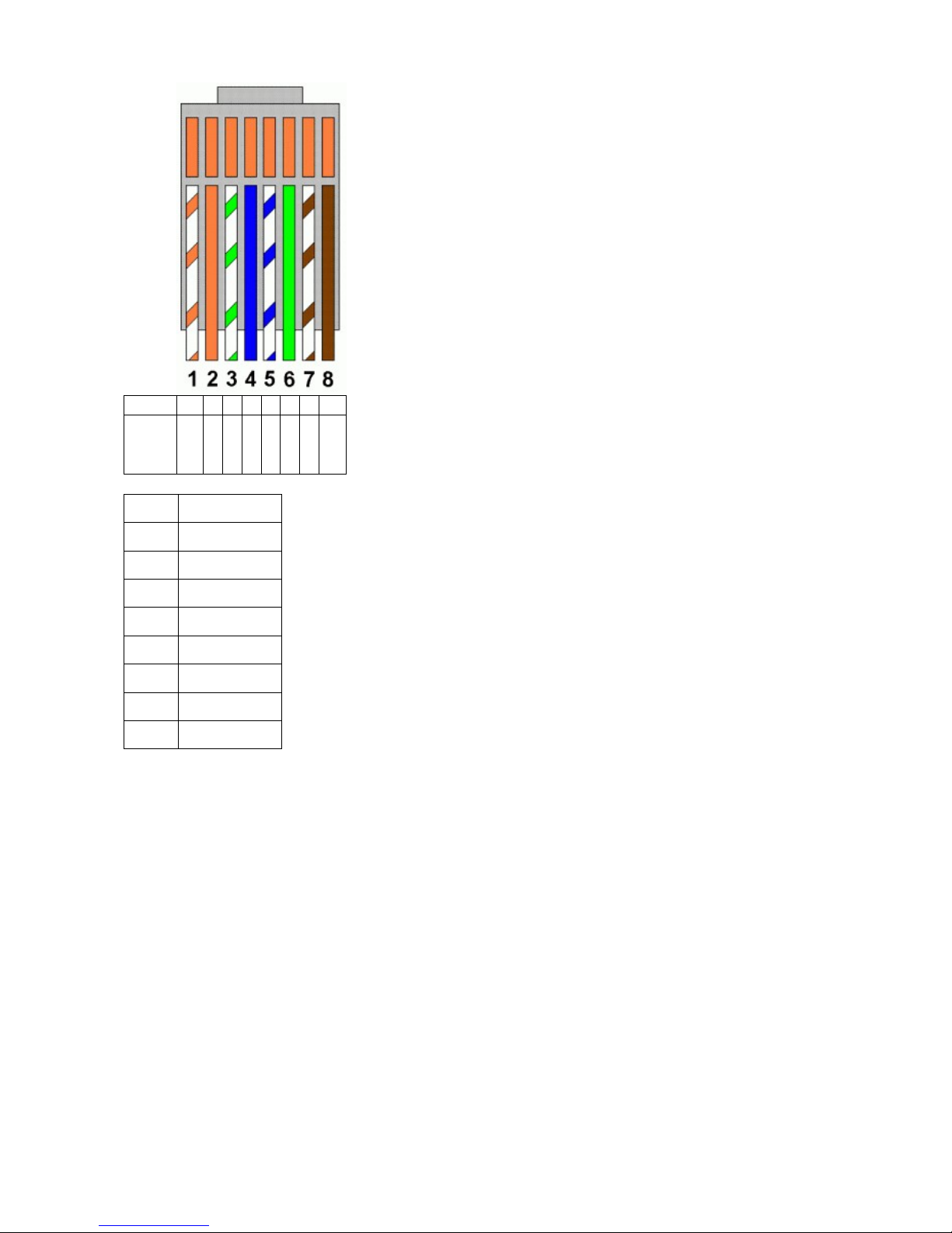
PIN 1 2 3 4 5 6 7 8
Signal
RS4
85 +
5V RS
48
5 -
G
N
D
RS
23
2
T
X
RS
23
2
R
X
RS
23
2
RT
S
RS2
32
CTS
PIN Signal
1 RS485 +
2 5V
3 RS485 -
4 GND
5 RS232 TX
6 RS232 RX
7 RS232 RTS
8 RS232 CTS
RJ45 RS232 RS485 Pinout
 Loading...