

Page 1
3M MAXSecure
Printer Module
Maintenance Manual
Manual No. 980286-001 Rev. A
Page 2

Page 3

FOREWORD
This manual contains service and repair information for 3M MAXSecure Printer Modules manufactured by the
3M Corporation,St. Paul, Minnesota. The contents include maintenance, diagnosis and repair information.
TECHNICAL SUPPORT
For technical support, users should first contact the distributor that originally sold the product—phone +1 (800)
344 4003 to locate the nearest 3M Distributor.
COPYRIGHT NOTICE
This document contains information proprietary to 3M Corporation. This document and the information
contained within is copyright by 3M Corporation and may not be duplicated in full or in part by any person
without prior written approval of 3M..
While every effort has been made to keep the information contained within current and accurate as of the date of
publication, no guarantee is given or implied that the document is error-free or that it is accurate with regard to
any specification.
This information is not intended as a license to practice or infringe on the patents of this company or others. 3M
Corporation reserves the right to modify, update or revise this information at any time without notice.
TRADEMARKS
3M MAXSecure is a service mark, and 3M is a registered trademark of 3M Corporation. All other marks are
trademarks or registered trademarks of their respective holders.
FCC NOTICE:
This equipment has been tested and found to comply with the limits of a Class A digital device, pursuant to Part
15 of the FCC Rules. These limits are designed to provide reasonable protection against harmful interference
when the equipment is operated in a commercial environment. This equipment generates, uses and can radiate
radio frequency energy and, if not installed and used in accordance with the instructions, may cause harmful
interference to radio communications. However, there is no guarantee that interference will not occur in a
particular installation. Operation of this equipment in a residential area is likely to cause harmful interference in
which case the user will be required to correct the interference at their own expense.
CSA NOTICE:
This equipment does not exceed Class A limits per radio noise emissions for digital apparatus set out in the Radio
Interference Regulation of the Canadian Department of Communications. Operation in a residential area may
cause unacceptable interference to radio and TV reception requiring the owner or operator to take whatever
steps are necessary to correct the interference.
Ce matériel ne dépasse pas les limites de Classe A d’émission de bruits radioélectriques pour les appareils
numériques telles qu’établies par le ministère des Communications du Canada. L’exploitation faite en milieu
résidentiel peut entraîner le brouillage des réceptions radio et télé, ce qui obligerait le propriétaire ou l’opérateur
à prendre les dispositions nécessaires pour en éliminer les causes.
iiiiii
Page 4

Page 5

TABLE OF CONTENTS
CHAPTER 1 GENERAL DESCRIPTION
1.1 PRINTER MODULE DESCRIPTION ..................1-1
1.1.1 Clear CardMaterial Feed, Shear,and Flip-Over ··············1-3
1.1.2 Print Station ·······························1-3
1.1.3 White CardFeeder Station ························1-4
1.1.4 Card AssemblerStation··························1-5
1.2 OPTIONS AND ACCESSORIES ....................1-5
1.3ABOUTTHISMANUAL........................1-5
1.4 CAUTIONARY NOTES.........................1-6
1.5 PACKAGING CONSIDERATIONS ...................1-9
1.6 PREPARING A STATIC-SAFE WORK AREA...............1-9
1.7 ENVIRONMENTAL AND SHOCK PROTECTION . . . ........1-9
CHAPTER 2 INSTALLATION AND OPERATION
2.1 INSTALLATION ............................2-2
2.1.1 Unpacking ································2-2
2.1.2 Location Concerns ····························2-3
2.1.3 Adding theLaminator and DieCutter ···················2-3
2.1.4 Attaching Cables ·····························2-4
2.1.5 Cable Diagrams ·····························2-5
2.2 OPERATION..............................2-6
2.2.1 Controls andIndicators ··························2-6
2.2.2 LCD MessagesRelated to PrinterModule ·················2-7
2.2.3 LCD MessagesRelated to LaminatorModule ···············2-7
2.2.4 LCD MessagesRelated to EncoderModule ················2-8
2.2.5 LCD MessagesRelated to Adjustments,Testing, and MicrocodeDownloads 2-8
2.2.6 LCD MessagesRelated to Cleaning ····················2-8
2.2.7 Print HeadLatch and ReleaseLevers ···················2-9
2.2.8 Ribbon Installation ···························2-10
2.2.9 Card Media ·······························2-11
2.2.10 Clear CardMaterial Loads ·······················2-11
2.2.11 White CardFeeder Loading ······················2-12
2.2.12 Two- versesThree-Layer Selection ···················2-13
CHAPTER 3 THEORY OF OPERATION
3.1 COLOR FUNDAMENTALS ......................3-1
3.2 PRINTER INTRODUCTION ......................3-5
3.3 CIRCUITRY ..............................3-8
Page 6

CHAPTER 4 TROUBLESHOOTING
4.1 DIAGNOSING BASIC PRINTER PROBLEMS ..............4-2
4.2 DIAGNOSING COMPUTER INTERFACE PROBLEMS .........4-5
CHAPTER 5 REPLACEMENT PROCEDURES
5.1 REQUIRED TOOLS ..........................5-2
5.2 PART REPLACEMENTS ........................5-3
5.2.1 Case Removal ······························5-3
5.2.2 White CardFeeder Station Removal ···················5-4
5.2.3 White CardFeeder Station Replacements ·················5-5
5.2.4 Upper ClearCard Station Removal ····················5-6
5.2.5 Upper ClearCard Station ComponentReplacements ···········5-7
5.2.6 Lower ClearCard Station Removal ····················5-8
5.2.7 Lower ClearCard Station Components ··················5-9
5.2.8 Card AssemblyStation Removal·····················5-10
5.2.9 Card AssemblyStation Component Replacements············5-11
5.2.10 Print HeadReplacement ························5-12
5.2.11 Fan Replacement ···························5-17
5.2.12 Ribbon SensorReplacement ······················5-18
5.2.13 Cleaning RollerSpring Clip Replacement················5-19
5.2.14 Front BeltRemovals ··························5-20
5.2.15 Printer StationRemoval ························5-21
5.2.16 Printer StationMotors and RearBelts and Sensors ···········5-22
5.2.17 Ribbon SupplySpindle and ClutchReplacements ···········5-24
5.2.18 Ribbon TakeUp Spindle Replacements ················5-26
5.2.19 Print StationCard Sensor ·······················5-28
5.2.20 CPU Boardand Socketed ICRemovals·················5-29
5.2.21 Extension PCBACircuit Board andSocketed IC Replacements ·····5-30
5.2.22 Clear CardStation Controller BoardReplacements ···········5-31
5.2.23 Power SupplyReplacements ······················5-32
5.2.24 Operator PanelReplacement ·····················5-33
CHAPTER 6 MAINTENANCE AND ADJUSTMENTS
6.1 CLEANING MATERIALS ........................6-2
6.2 CLEANING ..............................6-2
6.2.1 Print HeadCleaning ···························6-3
6.2.2 Replacing CleaningRoller Sheath ·····················6-4
6.2.3 Cleaning Card-Feedand Card-Transport Rollers ·············6-5
6.3 ADJUSTMENTS ............................6-6
6.3.1 Print HeadResistance ··························6-6
6.3.2 Peel BarAdjustment ···························6-6
6.3.3 Image Centering ·····························6-8
6.3.4 Pressure RollerPosition ·························6-10
6.3.5 Stepper BeltTension Adjustment ····················6-11
6.3.6 Front BeltTension Adjustments ·····················6-14
iv
Page 7

APPENDIX A TEST SOFTWARE
A.1 INSTALLATION ............................A-1
A.2 OPERATION .............................A-1
A.2.1 Launching theCard Printer TestSoftware ················A-2
A.2.2 Changing theCOM Port ·························A-3
A.2.3 Operating inTerminal Mode ·······················A-4
A.2.4 Typical SubList ·····························A-5
A.2.5 Typical PotAdjustment Selection ·····················A-6
A.2.6 Downloading Firmware ·························A-7
TABLE OF FIGURES
Figure 2-1. Packaging Materials .......................2-2
Figure 2-2. Laminator Installation.......................2-3
Figure 2-3. Cables. .............................2-4
Figure 2-4. Cable Wiring. ..........................2-5
Figure 2-5. Printer Controls and Indicators. .................2-6
Figure 2-6. Print Head Latch and Release Levers. ..............2-9
Figure 2-7. Ribbon Installation. ......................2-10
Figure 2-8. Clear Card Material Loads....................2-11
Figure 2-9. White Card Hopper Loading. .................2-12
Figure 2-10. Card Layer Selection Lever...................2-13
Figure 3-1. 3M MAXSecure Card Path. ...................3-7
Figure 3-2. Block Diagram. .........................3-9
Figure 4-1. Problems Duplicated by a Test Print. ..............4-2
Figure 4-2. Interface Diagnostic Flow. ....................4-5
Figure 5-1. Case Fasteners. .........................5-3
Figure 5-2. White Card Feed Station Removal. ...............5-4
Figure 5-3. White Card Feeder Components. ................5-5
Figure 5-4. Upper Clear Card Station Removal. ...............5-6
Figure 5-5. Upper Clear Card Station Replaceable Components. ......5-7
Figure 5-6. Lower Clear Card Station. ....................5-8
Figure 5-7. Lower Clear Card Station Components. .............5-9
Figure 5-8. Card Assembly Station Removal. ................5-10
Figure 5-9. Card Assembly Station Components...............5-11
Figure 5-10. Print Head Upper Fastener Removal. .............5-12
Figure 5-11. Print Head Assembly Fasteners.................5-13
Figure 5-12. Print Head Assembly Parts. ..................5-14
Figure 5-13. Print Head Connectors.....................5-15
Figure 5-14. Properly positioned Print Head. ...............5-16
Figure 5-15. Fan Replacement. ......................5-17
Figure 5-16. Ribbon Sensor. ........................5-18
Figure 5-17. Cleaning Roller Spring Clip...................5-19
v
Page 8

Figure 5-18. Front Belt Removals. .....................5-20
Figure 5-19. Printer Station Removal. ...................5-21
Figure 5-20. Printer Station Rear Parts....................5-23
Figure 5-21. Supply Spindle Assembly....................5-25
Figure 5-22. Ribbon Take Up Spindle. ...................5-27
Figure 5-23. Printer Station Card Sensor...................5-28
Figure 5-24. CPU Board...........................5-29
Figure 5-25. Extension PCBA. .......................5-30
Figure 5-26. Clear Card Station Controller Board. .............5-31
Figure 5-27. Power Supply Removal. ...................5-32
Figure 5-28. Operator Panel Board Removal. ...............5-33
Figure 6-1. Cleaning Materials........................6-2
Figure 6-2. Print Head Cleaning. ......................6-3
Figure 6-3. Changing the Upper Cleaning Roller ..............6-4
Figure 6-4. Card Transport Rollers. .....................6-5
Figure 6-5. Peel Bar Fasteners. .......................6-7
Figure 6-6. Lower Clear Card Feeder Pressure Roller Adjustment. .....6-10
Figure 6-7. Stepper Motor Fasteners. ...................6-11
Figure 6-8. Stepper Motor Belt Tensioning Fixture..............6-12
Figure 6-9. Stepper Belt Tensioning. ....................6-13
Figure 6-10. Front Belt Tension Adjustments. ...............6-14
vi
Page 9
CHAPTER 1
GENERAL DESCRIPTION
1.1 PRINTER MODULE DESCRIPTION
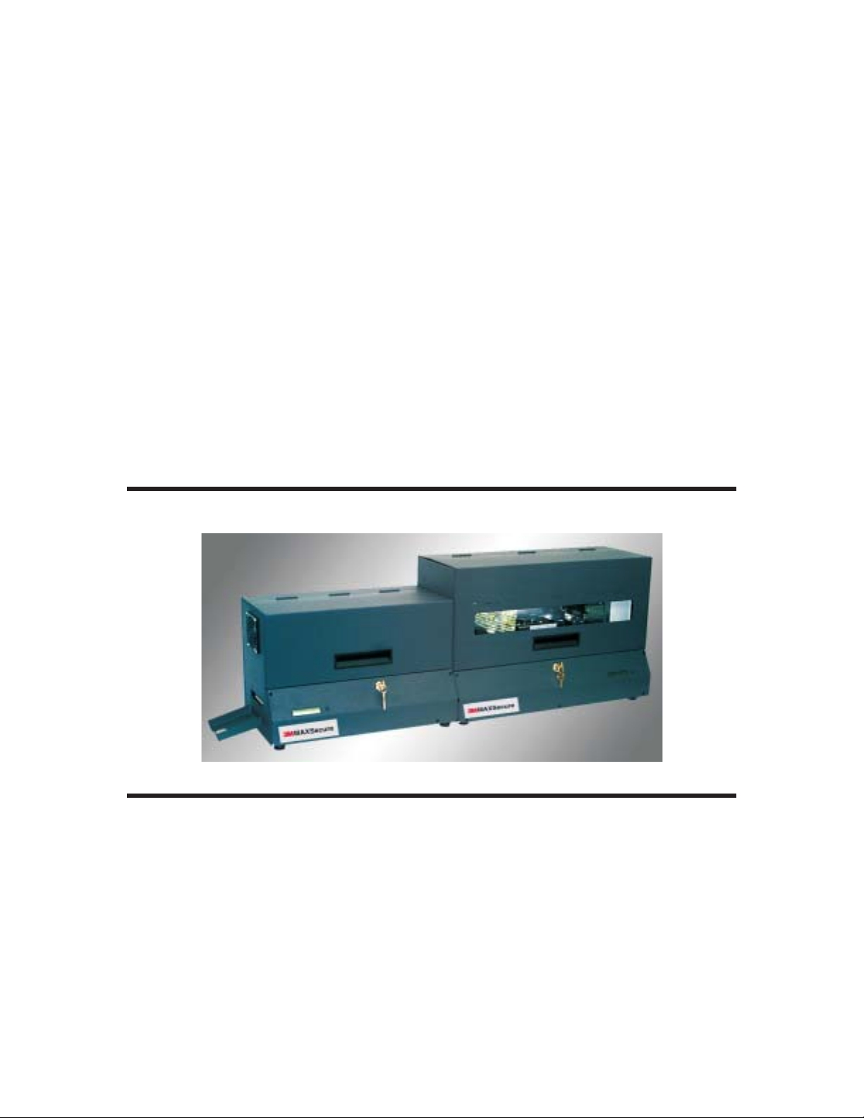
3M MAXSecure Printer Modules can operate as stand-alone card imaging devices or, as shown
above, become part of a larger system that can also include a 3M Lamination and Die Cutter
Module. 3M MAXSecure can also include a Magnetic Stripe Encoder Module (not shown).
3M MAXSecure can produce either two- or three-layer cards composed of either a Clear Card
and a White Card or a white card sandwiched between two Clear Cards. Clear Card imaging
occurs first. A Clear Card can receive full color CMY (cyan, magenta, yellow) and/or black resin
imaging. Imaging on the White Card can occur next. The White Card can receive Kr (Black
Resin) monochrome images. A second Clear Card serves to prolong card life and protect any
image placed on the White Card. Notably, an image placed on the White Card ends up on the
side opposite the Clear Card image. Security imprints appear on the side of the White Cards that
980286-001 Rev. A 1-1
Page 10
CHAPTER 1
GENERAL DESCRIPTION
receive no image by the Printer Module. On the finished cards, however, these images underlie
the Clear Card image.
After imaging, the Printer Module assembles and delivers a Clear and White Card to the
Laminator and Die Cutter Module. For three-layer cards, a second Clear Card follows. An
attached Laminator and Die Cutter Module fuses the Clear and White Card material and die
cuts the result to a standard credit/debit/etc card size.
Because the image on the Clear Card faces the White Card, scratches and ultraviolet radiation
have little affect on this image. Resin images offer substantial resistance to wear factors without
needing added protection, but for three-layer cards, an additional Clear Card maximizes wear
resistance. These features result in cards that can accept a fair amount of abuse and, with
reasonable treatment, can remain in service for 10 years.
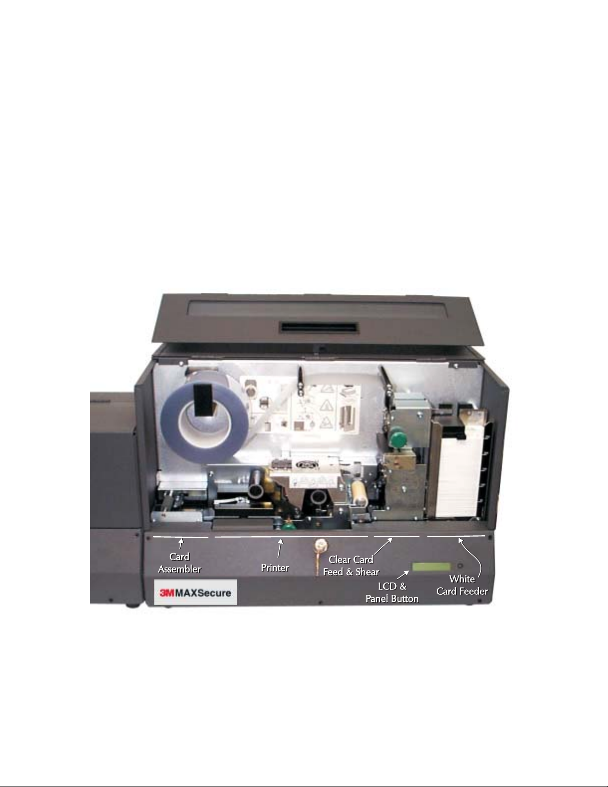
Figure 1-1 shows the Printer Module assemblies visible with the cover raised.
Figure 1-1. Major Assemblies
1-2
980286-001 Rev. A
Page 11

CHAPTER 1
GENERAL DESCRIPTION
1.1.1 Clear Card Material Feed, Shear, and Flip-Over
The upper part of this assembly contains a motor and a shear. The middle part has two
sensors—one for signaling the shear point and another to sense splices. The lower part
implements flip-overs of a second Clear Card.
All three parts of the assembly have rollers that move the material, due either to a manual
advance or by a motor powered drive roller. Clear Card material feeds off of a roll and into a slot
in the top of this assembly and then down vertical card guides.
The motor moves card-sized segments beyond the shear. A shear occurs when an associated
sensor detects material. As more media enters the upper part, the sheared segment enters either
the flip-over or the horizontal card guides. The assembly ultimately delivers Clear Cards to the
horizontal drive rollers.
Only one Clear Card surface has a bonding agent. So that the bonding material on the second
Clear Card can face the White Card, a solenoid-operated gate directs Clear Cards for a flip-over
before directing their entry into the horizontal guides.
Rolls of Clear Card material contain splices that require operator removals. A sensor in the
guides detects the splices, which results in related LCD messages to the operator.
1.1.2 Print Station
The printer first receives a Clear Card segment. Associated color imaging results from multiple
passes across the Print Head. Because the imaging occurs on the side opposite the viewed side,
Clear Cards receive mirrored images.
A motor-driven cam controls the position of the Print Head. Imaging occurs with a card and the
ribbon sandwiched between the lowered Print Head and the platen roller below. Card
transports not related to imaging occur with the Print Head raised sufficiently to allow freer
movement of cards, typically at faster rates.
Ribbon, having dye- and sometimes resin-coated panels, feeds from the supply to the take-up
spindles. During imaging, the coated side contacts the card, and the non-coated side contacts
the Print Head. Incremental ribbon advances accompany associated incremental advances of a
card across the Print Head. Card increments correspond to 300 dpi (dots-per-inch) image
resolution, which duplicates the density of elements across the Print Head.
Each dot imaged occurs from a ribbon dye transfer due to heat produced by an associated Print
Head element. For color, each element can produce 32 different heat levels, which correspond
to 32 different dye densities. When dots get superimposed on other dots to produce a
YMC-blended color, 32K combinations become possible. This imaging process is typically
called Dye Sublimation.
Resin imaging occurs at only one dot density. Resin, while excellent for bar codes and other solid
imaging, only responds well when transferred using a single temperature. An associated Print
Head element is either fully on or completely off. Solid imaging occurs for all internally
generated bar codes, text, and graphic elements. Users wishing to produce gradients of gray
while using resin imaging must resort to dithering and deliver an associated bit map. Because
980286-001 Rev. A 1-3
Page 12

CHAPTER 1
GENERAL DESCRIPTION
dithering creates a pixel (picture element) using a small dot matrix, reduced picture resolution
results. This resin imaging process is called Thermal Transfer. In contrast, users can create 32
levels of gray using YMC blends without loosing any image resolution.
By the time a card is fully imaged, a whole set of ribbon panels is used. Users can obtain ribbon
media in several configurations, each offering a cost optimization for a particular set of card
design requirements. For example, YMC ribbons cover the need for only Clear Card color
imaging without resin. The need for YMCKr ribbons occurs when resin imaging, of say bar
codes, must alsoappear, YMCKrKr ribbons serve those instances when black resin imaging must
occur on both the Clear and White cards.
After completion of the Clear Card imagingand the card moves to the Card Assembler Station, a
White Card feed occurs. The feed injects the White Card directly into the horizontal card guides.
White Cards can only receive black resinimages. Also, as stated previously, imaging depends on
a remaining unused Kr ribbon panel. A second Clear Card, when used, receives no image.
A standard feature of all 3M Card printers lets users print bar-codes using any of the 10
printer-resident formats. An associated image results from entry of a single command line,
where a related set of parameters precedes the data. Data refers to the alphanumeric string that a
bar code reader decodes when scanning the card. Associated parameters format the bar code,
specify size and position, and determine whether or not an associated text string appears under
the bar code.
Sensors in the Printer assembly include one that detects incremental advances of the ribbon,
one that detects the presence of a card entering the horizontal card guides,and one that finds the
yellow ribbon panel following an operator initialization. All synchronized card and ribbon
movement within the Printer Station depends on these sensors. Two microswitches form
sensors that signalwhen the PrintHead has reachedan either fullyup or fullydown position.
Motors in the Printer assembly include a stepper for precise control of card positioning in the
card path and dc motors to advance ribbon and raise and lower the Print Head.
1.1.3 White Card Feeder Station
This assembly delivers White Cards placed in the Feeder to the horizontal card guides of the
Printer assembly. Included are a dc motor that powers two feed rollers and a Card Gate that lets
only one card feed at a time. White Card thickness for two-layer cards measures 0.022 inches,
while those used for three-layer cards measures 0.015 inches.
Cards easily pass through a gate opening one and one-half times the card thickness without
allowing multiple feeds or rubbing against the upper restraint. When cards fail to feed, a user
typically finds acard with excessivewarping. The frontpanel LCD indicatesOUT OF CARDSif a
card fails to appear at the Printer assembly before a related time out occurs.
1-4
980286-001 Rev. A
Page 13

CHAPTER 1
GENERAL DESCRIPTION
1.1.4 Card Assembler Station
After imaging, a Clear and a White Card come together in the Card Assembler. The card path
deepens here, so that a White Card can rest on top of a Clear Card. The assembly includes a
motor, a solenoid, and two sensors. After these card components come to rest in this assembly,
as signaled by the lower of the two sensors, the solenoid-coupled roller raises to push the cards
against the motor-powered drive roller. The powered roller then delivers these two layers to the
exit opening of the Printer Module. An attached Laminator and Die Cutter Module would sense
this event and draw the cards into its card path. The upper sensor signals the presence of cards at
the output. Until these cards are taken away, no new cards should enter for card assembly. An
attached Laminator and Die Cutter Module waits for a second Clear Card, in instances where
the Layer Lever is set to 3 Layer.
The sensors can detect two error conditions. The CLEAR AT EXIT error signals that a second
Clear Card has entered the assembly instead of the expected White Card. The WHITE AT EXIT
error signals that a second White Card has entered the assembly prior to removal of a previously
assembled set.
1.2 OPTIONS AND ACCESSORIES
A Full Complement of Card and Ribbon Supplies—distributors of 3M Products stock these
items in order to assure that 3M MAXSecure users can obtain supplies that consistently produce
the best possible results.
1.3 ABOUT THIS MANUAL
3M Products has directed the Information contained in this manual at returning Printer module
functions to normal operation in the shortest time possible. With this in mind, service personal
should focus on items listed in the recommended spares list. Avoid lower level replacements
whenever possible. Service personnel should keep a log of the repairs made in support of the
concept of continuous product improvement. Chapters include: General Description,
Installation and Operation, Theory of Operation, Troubleshooting, Part Replacement
Procedures, and Maintenance and Adjustments. Appendix A describes software developed for
testing 3M MAXSecure printers.
Follow the instructions as closely as possible. When unsure of any procedure, please contact
either a 3M Products Service Representative (contact 3M Product Management for nearest
representative) or 3M Products Technical Support at 1-800-344-4003 or 805-578-1800.
3M Products stocks all commonly used replacement parts for 3M MAXSecure printers. A list of
the recommended spares appears in this Chapter. For depot repairs, contact 3M Product Sales
to place orders and to establish a program for bulk purchases and credited returns of warranted
parts.
980286-001 Rev. A 1-5
Page 14
CHAPTER 1
GENERAL DESCRIPTION
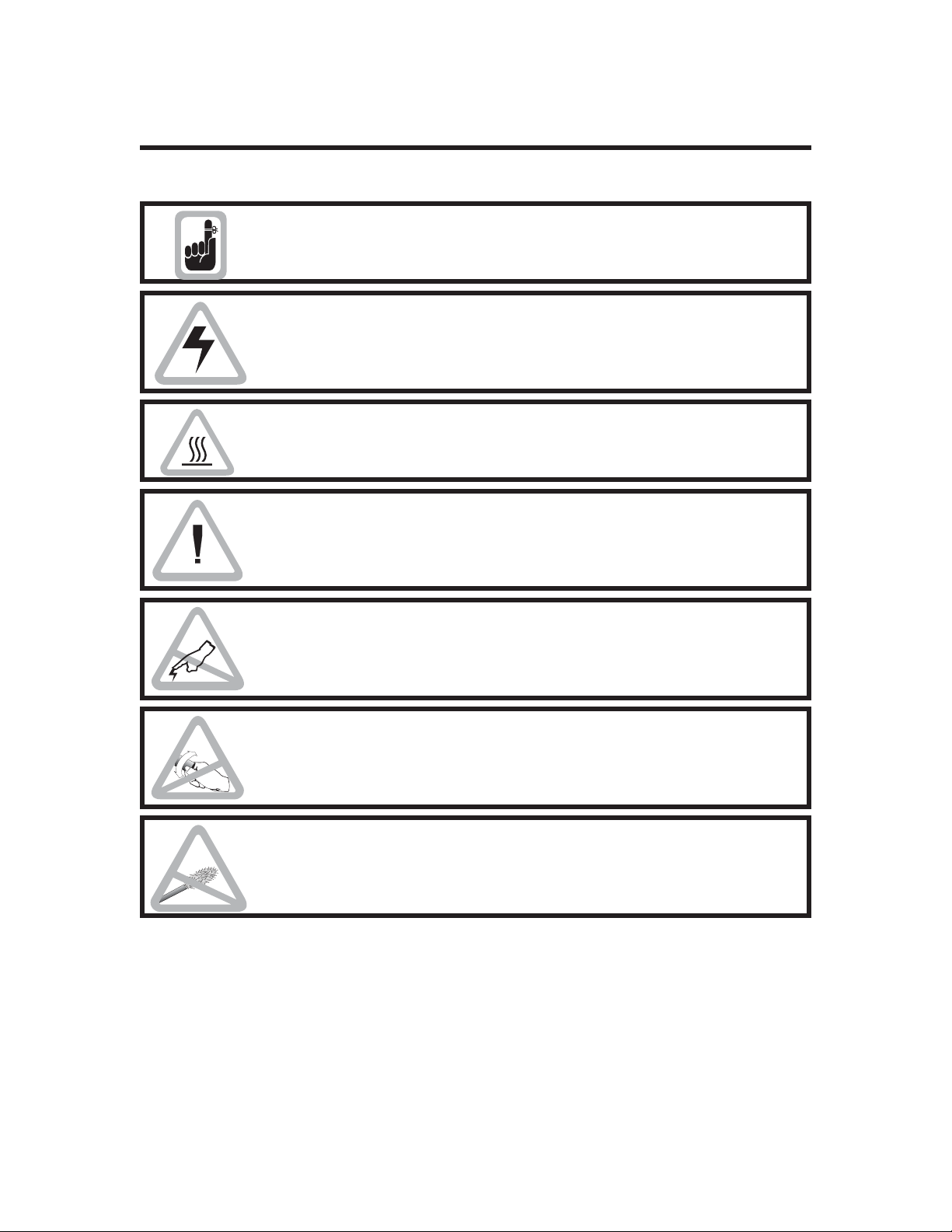
1.4 CAUTIONARY NOTES
Exercise reasonable care when servicing the printer, as follows:
Other than prescribed operator maintenance, only qualified personnel
should remove the case or otherwise attempt to repair this equipment. 3M
Products offers training to those wishing to service this equipment.
Servicing personnel must avoid touching exposed circuitry. Inputs to the
Power Supply operate at power line voltages. Any removal of protective
insulation can expose dangerous voltages. Always remove the power cord
when effecting repairs.
During printing, the Print Head operates at an elevated temperature.
Exercise caution when touching the parts on or near these areas.
Servicing Personnel should avoid any rough handling of the printer or its
component parts. The Print Head in particular requires careful handling.
Never lower the Print Head onto any object other than the card and
ribbon media.
An electrostatic discharge (ESD) of energy can damage or destroy the print
head and other electronic Printer Module components. People can acquire
such charges while moving around. ESD problems increase as the
humidity drops.
Users should not twist the Ribbon Take Up spindle manually. Doing so
unnecessary stresses the associated belt. Any slack left after a ribbon
installation gets removed during the initialization produced by pressing the
panel button.
To avoid deposits, clean only with fiber free Cleaning Swabs and
99-percent or better pure alcohol.
1-6
980286-001 Rev. A
Page 15

Part Replacement Spares
CHAPTER 1
GENERAL DESCRIPTION
Recommended Quantity
(Per 100 Printers)
A/R
5
5
5
5
5
5
10
1
3
1
1
9
A/R
A/R
A/R
A/R
A/R
2
2
1
A/R
2
2
2
1
2
15
10
2
5
1
2
1
2
10
2
2
2
2
2
5
2
2
2
5
10
2
Item Part No.
Lock Set for Enclosure
Kit, Print Engine
Kit, White Card Feeder
Kit, Clear Material Cutter
Kit, Clear White Material Entry Assembly
Kit, Printer Exit
Kit, Electronics, Printer
Kit, Roller, Card Feeder
Kit, Power Supply Fuse (Set of 10)
Kit, Main Circuit Board, Printer
Kit, Head Up/Down Sensor Switch
Kit, Cleaning Roller Clip
Kit Pressure Roller (Set of 5)
Kit, M4 x 8, Flat Head Phillips Screws (Set of 100)
Kit, M4 x 8, Pan Head Phillips Screws (Set of 100)
Kit, Printer Enclosure (Light Gray)
Kit, Printer Enclosure (Dark Gray)
Kit, Rubber Foot, Base
Kit, Printer Input/Output Extension Board
Kit, Printer AC Power and Filter
Kit, AC Power Switch (Set of 5)
Kit, Forcep, Curved
Kit, Solenoid
Kit, Ribbon Sensor
Kit, Ribbon Spindles
Kit, Clear Material Shear
Kit, Clutch Assembly
Kit, Exit Pressure Roller Assembly
Kit, Upper Cleaning Roller
Kit, Power Supply Assembly 120/240 Auto Ranging
Kit, DC Motor
Kit, Stepper Driver IC (L6219 at U12)
Kit, Flag Sensor
Kit, DC Motor Driver IC
Kit, Cleaning Roller Bearing
Kit, Ribbon Take Up O-Ring Belt
Kit, Rear Main Drive 0.08P, 40Deg, 63T
Kit, Belt, 0.080P, 40Deg, 88T x 3(1/8)
Kit, Belt, 0.080P, 40Deg, 63T x 3(1/8) (Set of 5)
Kit, Front Right Encoder Roller Drive, Belt 50T x 3 (1/8)
Kit, Front Left Encoder Roller Drive, Belt 95T x 3 (1/8)
Kit, Cam, Printhead Lift
Kit, PCBA, LCD Display
Kit, Timing Belt, 105T x 1/8 (Feeder)
Kit, Fan, Print Head
Kit, Stepper Motor
Kit, Replacement Print Head—Style 2
Kit, Knob, Max
105901-067
105901-203
105901-205
105901-207
105901-208
105901-063
105901-233
105901-226
105901-013
105901-218
105901-018
105901-019
105901-029
105901-032
105901-033
105901-211
105901-212
105901-037
105901-042
105901-050
105901-051
105901-052
105901-055
105901-057
105901-058
105901-231
105901-241
105909-005
105909-010
105909-020
105909-021
105909-024
105909-026
105909-028
105909-033
105909-038
105909-040
105909-043
105909-044
105909-045
105909-046
105909-058
105909-089
105909-098
105909-099
105901-230
105909-112
105901-087
980286-001 Rev. A 1-7
Page 16

CHAPTER 1
GENERAL DESCRIPTION
Spare Accessories
Recommended
Quantity
(Per 100 Printers)
A/R
A/R
A/R
A/R
A/R
A/R
A/R
A/R
A/R
10
A/R
A/R
A/R
Kit, Cleaning Core
Interface Cable
Power Cord (Domestic)
Power Cord (Europe)
Kit, Feeder, Weight
Kit, Cleaning Card
User’s Guide
Windows Drivers (NT and 95)
Kit, Cleaning Swab
Kit, Ribbon Take Up Core
Kit, Cleaning Core Spindle Assembly
Kit, Foam and Box (Printer or Laminator)
Kit, Maintenance Manual
Item Part No.
105901-001
300055-001
300020-001
300020-002
105901-036
105901-056
980279-001
105901-047
105909-057
105909-035
105901-061
105901-054
105901-227
1-8 980286-001 Rev. A
Page 17

CHAPTER 1
GENERAL DESCRIPTION
1.5 PACKAGING CONSIDERATIONS
The factory cartons include a printer placed inside a protective ESD (Electrostatic Discharge)
bag and suitable form-fitting foam cushions. Testingof this packaging hasconfirmed its ability to
withstand the forces required by equipment transporters. If any other shipping materials are
used, related shipping damage may not be covered by the warranty. If necessary, order
replacement factory-approved shipping materials from a 3M MAXSecure distributor.
1.6 PREPARING A STATIC-SAFE WORK AREA
To avoid component damage while performing troubleshooting and repair procedures, service
personnel should prepare a static-safe working area. This area should include a properly
grounded, conductive, cushioned mat to rest the Printer Module on and a conductive wrist strap
to ground the servicing technician. (Most electronic supply stores carry ESD protective devices.
For a local supplier, contact 3M Corporation at 1-800-328-1368 or 512-984-1800).
1.7 ENVIRONMENTAL AND SHOCK PROTECTION
Avoid extremes of temperature and humidity or mishandling. These conditions can damage
most electronic equipment.
When moving the printer from a cool, dry location to a warmer, more humid location, allow the
printer to temperature stabilize for at least 30 minutes before opening the protective ESD bag.
Otherwise, moisture can condense on the surface of many components. Moisture can degrade
performance or even damage some components.
Avoid rough handling. Careful handling can avoid possible mechanical damage that might
otherwise result from dropping or impacting the printer on a hard surface.
980286-001 Rev. A 1-9
Page 18

CHAPTER 1
GENERAL DESCRIPTION
1-10 980286-001 Rev. A
Page 19

CHAPTER 2
INSTALLATION AND OPERATION
This chapter includes information on the following:
• Unpacking
• Attaching a Laminator and Die Cutter
• Printer Module Cables
•
Printer Controls and Indicators
•
Ribbon Installation
•
Clear Card Installation
•
White Card Installation
Similar descriptions also appear in the associated User’s Guide and other manuals shipped with
the printer. The intent here is to make this manual as complete as possible for the targeted
service provider. Operations related to software applications and the Windows Driver do not
appear in thismanual. Installation andoperation of theTest Software appearsin Appendix A.
980286-001 Rev. A 2-1
Page 20

CHAPTER 2
INSTALLATION AND OPERATION
2.1 INSTALLATION
2.1.1 Unpacking
Figure 2-1 shows the packaging materials used to ship the Printer Module.
Note that customers should keep these materials on hand forfuture shipping needs. The product
warranty may not cover a printer damaged during shipment using other shipping materials. If
necessary, users should order replacements before shipping the Printer Module.
Figure 2-1. Packaging Materials
2-2
980286-001 Rev. A
Page 21

CHAPTER 2
INSTALLATION AND OPERATION
2.1.2 Location Concerns
Users should avoidlocations with heavy concentrations of airborne contaminates. Until ready to
use, keep Clear Card material and White Cards in their cartons. Such care also applies to
Cleaning Roller Sheaths. Handle all ribbon and card media in a way that avoids contamination.
Fingerprints and other such contaminants can lower image quality. Select a location that offers
easy access to all sides and unrestricted air flow for ventilation. Avoid locations that experience
extremes in temperature and/or humidity.
2.1.3 Adding the Laminator and Die Cutter
Figure 2-2 shows how the Printer Module and Laminator and Die Cutter fasten together.
CAUTION: To avoid damage, separate the Modules prior to any move to a new location.
Step 1. As shown, align the left side of the Printer Module with he right side of the
Laminator and Die Cutter Module.
Step 2. Lift the Laminator and Die Cutter Module to engage the hooks with the Printer
Module slots. Make sure that the pin on the Laminator Module aligns with the slot
in the Printer Module.
Figure 2-2. Laminator Installation.
980286-001 Rev. A 2-3
Page 22

CHAPTER 2
With ferrites at each end.
INSTALLATION AND OPERATION
2.1.4 Attaching Cables
Figure 2-3 shows the Rear Panel of the Printer Module. This panel has the following:
Power ON-OFF Switch
•
Power Connector
•
Parallel Port DB-25 Connector (e.g., LPTx)
•
Module Interconnect DB-9 Connector
•
Figure 2-3 shows the cables to the host computer and the cable that interconnects the Printer
Module to a Laminator and Die Cutter Module. The internal power supply automatically adjusts
to most of the outlet voltages encountered world wide. Always connect the Power Cable last.
Figure 2-3. Cables.
2-4
980286-001 Rev. A
Page 23

2.1.5 Cable Diagrams
Figure 2-4 shows the cable wiring.
CHAPTER 2
INSTALLATION AND OPERATION
HOST
STROBE
DATA 0
DATA 1
DATA 2
DATA 3
DATA 4
DATA 5
DATA 6
DATA 7
ACK/
BUSY
PAPER ERR.
READY
INIT
ERROR/
N/A
N/A
N/A
SIG. GND
SIG. GND
SIG. GND
SIG. GND
SIG. GND
SIG. GND
SIG. GND
DB-25
Pin No.
1
2
3
4
5
6
7
8
9
10
11
12
13
14
15
16
17
18
19
20
21
22
23
24
25
DB-25
Pin No.
1
2
3
4
5
6
7
8
9
10
11
12
13
14
15
16
17
18
19
20
21
22
23
24
25
PRINTER
MODULE
STROBE
DATA 0
DATA 1
DATA 2
DATA 3
DATA 4
DATA 5
DATA 6
DATA 7
ACK/
BUSY
PAPER ERR.
READY
INIT
ERROR/
N/A
N/A
N/A
SIG. GND
SIG. GND
SIG. GND
SIG. GND
SIG. GND
SIG. GND
SIG. GND
Female DB-25 to Male DB-25
PRINTER
MODULE
N/A
RxD
TxD
DTR
GND
DSR
RTS
CTS
RI
DB-9
Pin #
1
2
3
4
5
6
7
8
9
DB-9
Pin #
1
2
3
4
5
6
7
8
9
LAMINATE
MODULE
N/A
RxD
TxD
DTR
GND
DSR
RTS
CTS
RI
Female DB-9 to Male DB-9
Figure 2-4. Cable Wiring.
980286-001 Rev. A 2-5
Page 24

CHAPTER 2
INSTALLATION AND OPERATION
2.2 OPERATION
2.2.1 Controls and Indicators
Figure 2-4 shows the Push Button and LCD (liquidcrystal display) that appear on thefront of the
Printer Module as well as the rear-panel-mounted Power Switch. As shown, the LCD
communicates operational status to users.
After ribbon installation, users press and hold the Panel Button for about three seconds or until
hearing the ribbon begin to advance. This initialization positions a yellow panel for subsequent
printing. Users also press and can immediately release the button to proceed after correcting an
error condition. For example, the system can sense a card jam and suspend operation but
cannot sense the removal and discarding of the offending card. Until a user presses the Panel
Button, system operation remains suspended and waits for this signal to resume.
The Panel Button can also initiate Test Prints. To initiate a Test Print, hold the Panel Button
pressed while turning power on. Resulting Test Prints contain information on the configuration
of the associated printer. Test Prints also offer an easy-to-obtain printer output for servicing
personnel that wish to see image anomalies or the effect produced by a printer adjustment.
Figure 2-5. Printer Controls and Indicators.
2-6
980286-001 Rev. A
Page 25

CHAPTER 2
INSTALLATION AND OPERATION
2.2.2 LCD Messages Related to Printer Module
LCD Message Description
INITIALIZING Power-On Initialization in progress
READY Ready to Receive Commands
PRINTING Printer Busy
CLEAR FEEDER ERR No Response from Clear Card Feeder During Power-ON Checks
WAIT TEMPERATURE Print Head Cool-Down in Progress
REMOVE SPLICE Clear Card Splice Detected—Removal at Card Assembly Station Required
OUT OF CLEAR Install Clear Card Roll
OUT OF WHITE More White Cards Required
OUT OF RIBBON New Ribbon Required
SELECT WHITE Wrong Layer Selection for White Cards in Hopper
CLEAR AT EXIT Attempt to Place 2nd Clear in Exit
WHITE AT EXIT Attempt to Place 2nd White in Exit
EXIT FAILURE Error Sending Cards to Laminator
MECHANICAL ERR Card Jam Sensed
DOWNLOADING Printer Receiving Data
CLEAR TURN ERROR Error During Flip-Over of Third Layer
CUTTER ERROR Error at Clear Card Cutter
CLEAR AT ENTRY Remove Clear at Cleaning Roller
WHITE AT ENTRY Remove White Card at Cleaning Roller
SELF TEST Test Print in Process
2.2.3 LCD Messages Related to Laminator Module
LCD Message Description
WARMING UP Printer Waiting for Laminator
LAMINATOR BUSY Printer Waiting for Laminator
WAIT LAMINATOR Error Reprint Wait–Laminate Finishing
LAMINATOR ERR Error During Lamination
980286-001 Rev. A 2-7
Page 26

CHAPTER 2
INSTALLATION AND OPERATION
2.2.4 LCD Messages Related to Encoder Module
LCD Message Description
ENCODER BUSY Encoder is Busy; Printer Waiting to Send Card
ENCODING ERR Error During Encoding
WAIT ENCODER Error Reprint Wait–Encoder Finishing
CARD ENCODER A Card is in the Encoder
NO CARD ENCODER No Cards in Encoder
MAGNETIC ERROR Communications Error Between Printer and Encoder
CLEAN MAG HEAD Clean Magnetic Encoder
2.2.5 LCD Messages Related to Adjustments, Testing, and Microcode Downloads
LCD Message Description
COMMAND ERROR Command Not Recognized by Printer
PARAMETERS ERROR Command Received has Imporper Parameters
REMOVE CLEAR Can appear During Improper Sensor Adjustment
ERR NO SPLICE Cannot Detect Splices due to Sensor Adjustment
NO ACCESS Printer Password Required for Command Sent
FLASH ERROR Error Detected During Firmware Download
KEY TO EXIT Offers Exit Opportunity During Testing—Press Button
2.2.6 LCD Messages Related to Cleaning
LCD Message Description
CLEANING PRINTER Time to Clean Printer—Press Panel Button when Ready to Begin
REMOVE RIBBON Remove the Ribbon Before Continuing
REMOVE CARD Cleaning Card at Exit Requires Removal
NO CLEANING CARD Place New Cleaning Card at Clear Material Load Point
REMOVE CLEAR Remove Cleaning Card
CLEANING CUTTER
A Clear Card Shear Cleaning/Sharpening Sequence is Running (Follows Splice
Removal After OUT OF CLEAR Message)
2-8 980286-001 Rev. A
Page 27

CHAPTER 2
INSTALLATION AND OPERATION
2.2.7 Print Head Latch and Release Levers
Figure 2-6 shows the Latch and Release levers for the Print Head. Users open the Cover and
raise the Print Head for Cleaning Procedures and Ribbon Loading. The Print Head and Cover
must both remain down for card imaging and other printer operations.
Users should keep the cover closed as much as possible to reduce the exposure of internal
components to airborne contaminants. Any contaminants that find their way onto cards
traveling along the card path have a good chance of adversely affecting print quality.
Figure 2-6. Print Head Latch and Release Levers.
980286-001 Rev. A 2-9
Page 28

CHAPTER 2
INSTALLATION AND OPERATION
2.2.8 Ribbon Installation
Refer to Figure 2-7, and proceed as follows:
Step 1. Open the Cover, raise the Print Head, and remove any ribbon and ribbon core
still remaining in the printer.
Step 2. To prepare a new ribbon for installation, undo the tape keeping the ribbon
from unraveling. Then, rest both the ribbon and an empty core on end, on a flat
surface, and touching. Tape the loose ribbon end onto the empty core, and wind
some ribbon onto the core. For extra cores, order Part Number 105909-035. Users
needing to switch back and forth between different kinds of ribbons will need more
than the spare shipped with the printer.
Step 3. Push a prepared ribbon and ribbon core onto the supply and takeup spindles,
respectively. Note that the ribbon feeds off the top of the Supply Spindle and onto
the top of the Take-Up Spindle. This is very important. Damage to the Print Head
can occur if the ribbon side with dye ever contacts the Print Head. Therefore, be
very sure to install the ribbon properly.
Step 4. Latch down the Print Head, and close the printer cover.
Step 5. Remove any unfinished card from the exit mechanism.
Step 6. Press the Panel Button to initialize.
Do Not Twist
Figure 2-7. Ribbon Installation.
2-10
Hot
ESD Sensitive
980286-001 Rev. A
Page 29

INSTALLATION AND OPERATION
2.2.9 Card Media
3M Products offers the following Card media:
Description Part Number
Kit containing Clear Card roll and White Cards for 2-Layers
Kit containing Clear Card roll and White Cards for 3-Layers
104523-055
104523-060
2.2.10 Clear Card Material Loads
Refer to Figure 2-8, and proceed as follows:
Step 1. Place a roll of Clear Card Material onto the holder such that the loose end
feeds from the bottom of the roll.
Step 2. With power on, feed the loose end through the two sets of guide rollers and
then into the top of the Clear Card Feed Station. When sensed, the Printer Module
automatically advances the material to a point below the Shear.
CHAPTER 2
Figure 2-8. Clear Card Material Loads.
980286-001 Rev. A 2-11
Page 30

CHAPTER 2
INSTALLATION AND OPERATION
2.2.11 White Card Feeder Loading
Refer to Figure 2-9, and proceed as follows:
Step 1. Park the Card Weight at the top of the White Card Feeder.
Step 2. Place cards in the Input Tray. Note that cards can stick together for various
reasons, and users should effect a shuffle-like action on the stack prior to placing
cards into the White Card Feeder. Note that Magnetic Stripes, if present, should
face up and be nearer the back of the Feeder than the front. Preprinted Secure
Card imaging must face down.
Step 3. Place the Card Weight on top of the cards. Note that the Card Weight
increases the gripping of the Card Feed Rollers. Also, note that any accumulation
of contaminants on the Card Feed Rollers can lead to card feed slippage. Clean the
Card Feed Rollers when signaled by the LCD or after experiencing card feed
failures.
Figure 2-9. White Card Hopper Loading.
2-12
980286-001 Rev. A
Page 31

CHAPTER 2
INSTALLATION AND OPERATION
2.2.12 Two- verses Three-Layer Selection
Figure 2-10 shows the lever that sets the Printer Module for either two- or three-layer operation.
Be sure that the lever setting matches with the card thickness selected for use, as follows:
2-Layer Setting requires 0.022-inch card thicknesses.
•
3-Layer Setting requires 0.015-inch card thicknesses.
•
Figure 2-10. Card Layer Selection Lever.
980286-001 Rev. A 2-13
Page 32

CHAPTER 2
INSTALLATION AND OPERATION
2-14 980286-001 Rev. A
Page 33

CHAPTER 3
THEORY OF OPERATION
This chapter includes three major topics:
• Color Fundamentals
• Printer Module Card Path Elements
• Circuit Description
3.1 COLOR FUNDAMENTALS
Color refers to the hues seen in the visual spectrum. This spectrum consists of all the colors seen
in a rainbow or by the dispersal of white light through a prism. The extremes of this spectrum are
red (the longest wavelength perceivable) and violet (the shortest wavelength perceivable). The
remaining orange, yellow, green, etc., shades lie between the red and violet extremes.
Spectrums above and below the visual are called ultra violet and infrared, respectively.
Saturated colors are colors in their purest state. This means they contain no white (as in pastels)
or black (contrast reduction) components. A so-called trained observer can discern about 450
pure shades. If these colors are diluted by black, the ability to discern shades diminishes.
However, white dilution increases the number of colors discernible.
980286-001 Rev. A 3-1
Page 34

CHAPTER 3
THEORY OF OPERATION
When computers get involved in the color process such things as memory capacity and data
3
compression become factors. Fifteen-bit color yields 32x10
each pixel in the desired image. Twenty-four bit color yields 16x10
9
yields 4x10
shades. Note that the memory required for images expands substantially with the
shades and a requires 15-bits for
6
shades. Thirty-two bit color
number of shades. Compression attempts to reduce the memory requirements. Some
compression schemes only attempt to identify repeating colors. Others, such as JPEG, can treat
various amounts of change as if they were the same repeating colors. Carried to an extreme, a
posterized result would occur, and the color changes would step unnaturally.
In the color printing process, particular shades of color derive by mixing quantities of the basic
colors cyan, magenta, yellow, and sometimes black (usually referred to as CMY or
CMYK—where K designates black). When users choose some other color definition from their
application—e.g., hue saturation intensity (HSI) or red green blue (RGB)—a conversion to
CMY/CMYK must take place to support a printer. Mixing occurs at the level of each pixel. Pixels
serve as the basic elements of images. Pixels can comprise either one dot (the smallest printable
element) or a small matrix of dots, depending on the methodology used to form the images.
Offset printing and Dye Sublimation can produce a substantial range of colors within just one
dot. Color Monitors produce their range of colors using a red, green, and blue (RGB) three-dot
matrix. Scanners and digital cameras employ charge-coupled devices (CCDs) that deliver RGB
outputs.
Thermal Transfer and most Ink Jet printers produce their range of colors using larger dot
matrixes—typically up to four-by-four or equivalent dots—where each dot color can be a
fundamental (CMY), or the combination of fundamentals (RGB and black). Therefore, these
particular devices limit their dot colors to cyan, magenta, yellow, red, green, blue, black, and the
media color (usually white). The color perceived results from the optical mixing of the eight
possible color components contained in the matrix.
With eight dot colors possible, a four-by-four dot matrix can produce in excess of 4 billion
8
)
combinations ((4x4
). However, as long as the color components remain the same, the dots in
a matrix can be shuffled into any pattern without changing the color perceived. For example, a
matrix containing all-white dots except for one red dot produces the same shade of pink no
matter where in the matrix the red dot lies. Therefore, a matrix containing n dots can produce
each color in n different ways. Thismakes a four-by-four matrix capable of producing more than
8
268 million different shades ((4 x 4)
/16 + white). For monochrome printing, which is the only
matrix-based printing that users might want to apply to a 3M MAXSecure printer, this same
2
)
matrix can produce 16 different gray shades plus white ((4x4
/16 + white).
Mixing of dot colors in Offset Printing and Dye Sublimation occurs by controlling the amount of
each dye or ink that gets applied to each dot. Mixing in monitors occurs from control of beam
intensity, with three beams acting on the individual phosphors applied to CRTs (cathode ray
tubes).
Of all thesemethods, Dye Sublimationproduces the best quality printouts, because as is the case
for all 3M MAXSecure printers, each dot can have the full range of 15-bit color (32K shades) at
full 300 dpi resolution. In fact, even with resolutions equal, Dye Sublimation still has an
advantage over offset printing. Dye Sublimation creates a dot color by varying the density of the
CMY dyes. Offset printing creates a dot color by varying the diameter of the CMYK ink dots,
3-2
980286-001 Rev. A
Page 35

CHAPTER 3
THEORY OF OPERATION
which can make individual dots more observable and subject to moiré pattern generation. With
Dye Sublimation, users achieve essentially the continuous-tone quality of photographs.
Moiré patterns can become a factor when users generate either print files or hard copy
separations for offset printing. Users should ask the people that do their offset printing which
separation angles best reduce these patterns before risking a distorted result. Many applications
offer Print dialog options for these settings.
All the non Dye Sublimation print methods work because people perceive individual dot colors
only to the point the dots remain individually discernible. At sizes or distances where individual
dots cannot be seen, optical mixing occurs. To see individual dot intensities or colors, view the
monitor or printed page using an eye loupe or other such magnifier. Not all images require high
dot densities. The need for high dot density decreases as the viewing distance increases. For
example, a large roadside sign may require separations screened at only four lines-per-inch.
Note that press men use lines per inch, because of the screens used to vary dot size, and
computer users use dots per inch, but both refer to picture resolution.
Because a monitor and a printer produce color using different methods, users can expect
somewhat different results. A monitor uses an additive process, meaning a particular color
derives from intensity control. For example, a color moves toward the green by intensifying
excitation of green phosphors. Printed images, on the other hand, use a subtractive process.
These images display their color through reflected light—unlike monitors, which become a light
source created by excitation of phosphors. To create a particular printed color, the process must
subtract (that is, filter out and not reflect) the spectrum parts of the source illumination that do
not contribute to the color desired.
The light reflected off of the surface of a white card passes through the colored dyes deposited on
the surface of the card, both going and coming. The dyes used to form printed images serve as
filters of light that would otherwise reflect off of what is typically a white print media. In printed
images, complete filtration (or what serves as the maximum subtraction capability), results in
black. The absence of filtration results in the media color. In monitors, maximum beam
intensities (maximum additions) result in white, and minimum intensities produce black.
Because light reflected from print media depends on ambient lighting, users may get darker
images from a printer than they see on a monitor, particularly a monitor with a high intensity
setting.
Print illumination (generally from room or outdoor lighting) affects color for all printed images.
When a light source emits less in certain parts of the visual spectrum, a print illuminated by this
source by necessity reflects less of the associated colors. This is true even though the
corresponding light reflecting capability remains inherent in the print. Imagine, for example, the
effect of placing a color filter in front of a light source. Only the visual spectrum parts passed by
this filter reaches the print. Viewers can sometimes see subtle effects of this by observing the
same print under sunlight, incandescent lights, and fluorescent lights.
Sunlight radiates fairly evenly over the entire visual spectrum, having only a slight increase at the
center. Incandescent lights radiate far more on the red side than on the blue side of the visual
spectrum. Fluorescent lights radiate differently depending on their phosphor blends. Such
classifications as “Cool Light” and “Warm Light” refer to blue-rich and red-rich enhancements,
respectively.
980286-001 Rev. A 3-3
Page 36

CHAPTER 3
THEORY OF OPERATION
When close concern for color is important in displaying prints, users should find a similar
ambient setting for a color check. If a color is closely related to identifying a printed feature, users
may find themselves dealing with this level of concern, with skin tones typically offering the
greatest challenge. However, most applications tend to require a less critical evaluation. Usually,
what looks good in one setting tends also to look good in another setting, despite any subtle
differences in ambient lighting.
In scientific terms, the question “How white is my source?” is resolved by a side-by-side
comparison between a source in question and a heated black body radiator. The term “black
body” refers to a material that produces no color other than that which results from heating.
Imagine such a material first appearing reddish and then gradually appearing white hot followed
by bluish white as its temperature increases. These are the whites to which comparisons are
made. In the Graphic Arts industry, the following standards for white exist:
Region Black Body Temperature
US. 5000°K
Europe 6500°K
Note that a color image created for a U.S. print media will appear different when printed on a
European print media. Any white media used will have measurable color spectrum
characteristics that can accent or attenuate particular colors. Consider, for example, what might
happen to an image printed on a media having a bluish tinge.
Color is very much a function of the device either sensing or producing the color. A computer
monitor, for example,can produce very bright images, typically brighter than those produced by
a television set. A television set typically can produce a broader range of colors than can a
monitor. Television manufactures emphasize color range over brightness; monitor
manufacturers emphasize brightness over color range. While the forgoing compromises
generally hold true, each device manufacturer, in fact, takes a different perspective when
deciding which formulations to use in the red, green, and blue CRT phosphors.
Further complications arise with the addition of a color scanner to a system. These devices also
differ between manufacturers. WYSIWYG (what you see is what you get) from scanner to
monitor to printer gets complicated because of different device color ranges (Gamuts) and by
the different color systems used. A printed color outside the range of a scanner cannot make it to
a monitor. Users that attempt to use a computer application to edit an image received from a
scanner may add colors beyond the range of their printer. Notably, some applications issue
gamut warnings. Both monitors and scanners use the RGB system, while color printers use the
CMY/CMYK system.
An important concern is how a device handles colors beyond its range. If a device just
substituted the best color available, objects filled with blends, starting from inside the gamut and
ending at some point beyond the gamut, would loose their desired appearance. For example,
an object blending from say an orange to a red beyond the red range would abruptly stop
blending at the point the device could no longer produce a deeper shade of red. The remaining
blend would then have the same color. Some devices avoid this effect by compressing (re
mapping) the gamut. While compression maintains the desired effect, too much compression
produces posterizing. When this occurs, color changes appear unnaturally abrupt in some parts
of the image.
3-4
980286-001 Rev. A
Page 37

CHAPTER 3
THEORY OF OPERATION
3.2 PRINTER INTRODUCTION
3M MAXSecure color imaging requires three passes of a Clear Card media across the Print
Head. Clear Card media shuttles back and forth across the print head during this process. The
ribbon feeds between the image head and the card media and during printing advances from its
supply to its take-up reels in step with the advancing print media.
Heat, when generated at an image head element, transfers ribbon dye in a measured quantity
onto the print media. In color printing, the ribbon advances from one color panel to the next
between each imaging pass. A card exits to the Card Assembler following the last pass.
Monochrome printing for each black resin image requires additional passes.
3M MAXSecure printers employ an image head with a single row of 672 print head elements,
300 to the inch. Note that the capability for card coverage exceeds the needs of a standard card
size by 0.115 inch, or about 34 dots. This excess supports both programmable centering and full
bleed imaging. Each element can generate 32 different heat levels for color and a single heat
level for monochrome.
Figure 3-1 shows two views of a 3M MAXSecure Printer Module. Refer to the upper view for
components that transport the card and ribbon media and the labeling of major components.
Refer to the lower view for elements that sense media positions.
Motors and Solenoids
Printer Stations have two dc motors: one for the ribbon take up, and another to drive the cam
that raises and lowers the print head. For the required imaging precision, a stepper motor drives
the rollers that transport card media. A dc motor in the White Card Feeder and a steppper motor
in the Clear Card Feeder insert related card media. Another dc motor in the Card Assembler
station delivers card components to the exit slot.
Timing belts couple the upper two sets of rollers in the Upper Clear Card Feed and Shear
Station, including the related Manual Advance Knob. Timing belts also couple the two rollers in
the White Card Feed Station. Also note that the Printer Station stepper powers a set of rollers in
the Lower Clear Card Feed and Shear Station. An associated timing belt extends stepper drive
across the two stations.
A solenoid exists in the Card Assembler. When this solenoid releases, card components raise to
engage the upper roller, where dc motor drive can transport cards to the exit slot. At this point,
cards await theirremoval, either manuallyor by anattached Laminator andDie Cutter Module.
An additional solenoid in the Clear Card and Shear Station directs Clear Cards either directly to
the horizontal card guides or to the lower section for a flip-over. The second Clear Card of a
three-layer card transitions through the lower section.
980286-001 Rev. A 3-5
Page 38

CHAPTER 3
THEORY OF OPERATION
Sensors
During a print cycle, LED-Photo transistor sensors monitor the positions of the cards and the
advance of the ribbon. Note that two types exist—a beam interrupt type and a beam reflection
type. Switch sensors also exist that operate off of the cam that raises and lowers the Print Head.
These switches sense completion of head-up and head-down transitions.
Two ribbon sensors exist. One ribbon sensor can receive a beam reflection through the yellow
ribbon panels. Users can initialize the ribbon to these positions by pressing the Panel button.
This ribbon panel sensor also senses out-of-ribbon conditions. Operating in association with the
Flag sensor, the need for ribbon advance corrections is sensed. The number of flag slots counted
verses the sensing of the yellow panel for each colorimage produced serves as the basis forthese
corrections. As more ribbon accumulates on the Take Up spindle, a reduction in the amount of
take up occurs to keep line advances sufficiently even.
Three sensors exist in the Clear Card Feed and Shear Station—two sense reflections off of the
Clear Card material and one senses transmissions through the Clear Card material. Properly
setup, the transmission sensor can signal the presence of a splice. The reflection sensor signals
when a shear should occur to produces a card segment. The upper reflection sensing sensor
signals the presence (or absence) of Clear Card material in the card path.
Two more reflective sensors appear in the lower part of the Clear Card and Shear Station. The
upper-most sensor signals the need to switch from Clear Card Station drive to Printer Station
drive. The lower-most sensor signals the need to reverse Printer Station drive. As this drive
continues, the Clear Card enters the horizontal card path with its bonding agent facing down.
Note that the previous Clear Card entered the horizontal card path with its bonding agent facing
up, and a White Card entered between the two Clear Cards with its security imprints facing
down.
Two Card Assembly Station sensors exist—an upper beam interrupt type and a lower beam
reflection type. The upper sensor indicates when cards appear at the output slot. The lower
sensor produces a reflective signal that indicates the presence of a White Card. These sensors
can also signal errors caused by too many cards in the Card Assembly Station.
3-6
980286-001 Rev. A
Page 39

Manual
Advance Knob
Clear Card Feed
Rollers
Card
Path
Exit
Solenoid
CARD ASSEMBLER
STATION
Ribbon
Take Up
Stepper-Driven
Transport Rollers
Print Head
PRINTER
STATION
Ribbon
Supply
Platen
Roller
Print Head
Up/Down
Cam
Clear Card
Shear
Cleaning
Roller
Clear
Card
Material
Sensor
CLEAR CARD FEED
AND SHEAR STATION
Card Path
Solenoid
Clear Card
Flip-Over
Card Path
White Card
Feeder Rollers
WHITE CARD
FEED STATION
Select
Flag
Sensor
Head Up/Dn
Switch
Sensors
Input
Sensor
Cut
Sensor
Clear Reverse
Top Sensor
Clear Reverse
Bottom Sensor
Splice
Sensor
Card at
Output
Sensor
Card(s) in
Assembler
Sensor
Ribbon
Sensor
Figure 3-1. 3M MAXSecure Card Path.
980286-001 Rev. A 3-7
Page 40

CHAPTER 3
THEORY OF OPERATION
3.3 CIRCUITRY
As shown in Figure 3-2, the printer has the following circuits:
Print Head Circuitry
•
Motor Control Circuitry
•
Status Circuitry
•
Host and Module Interconnect Ports
•
Operator Panel Circuitry
•
If possible, spend some time with this figure. The intent is to offer another perspective to
descriptions given in other parts of the manual.
Printer Modules havethree printed circuit boards—a Main CPU board, an Extension board, and
a second Processor board that controls Clear Material feeds. The figure depicts soldered-in
circuit blocks without shading. The lighter shading indicates socketed ICs. The darker shading
indicates external assemblies connected to the circuit boards by cabling.
The Microcontroller determines all operations through data and address busses and control
signals. Flash memory contains the associated micro-code. Note also that the Address bus
primarily serves transfers involving the Flash and DRAM chips. Most other data transfers occur
with a chip enable or other Microcontroller signal.
Two types of status are collected—sensor and parameter. Analog comparators receive inputs
from the LED-Photo transistor detectors. The D/A Converter allows the Microcontroller to
trigger an integration signal sent to the comparators placed on the Extension board.
Comparators operate using single-slope integration as a basis for checking sensor levels.
Single-slope integration times the interval between the start of a sawtooth wave and the point an
analog comparator switches state.
Motors exist in two types—dc, and stepper. The solenoid and all dc motors, including the one in
the Shear, receive 24-volt dc power. This same supply powers a dc-to-dc converter that delivers
5-volt power to the remaining circuitry.
Print data, still in compressed bit-map form, enters the RAM. After reception, the Microcontroller
sends the data to the Print Head Drive circuitry. Decompression occurs after the Microcontroller
retrieves data and before its delivery to the Print Head Drive circuitry.
Word-by-word, the data shifts into the 672 print head registers that feed theelements of the print
head. Print Head registers receive the data in two serial streams from the Print Head Drive
circuitry. For Clear Card color printing, the Microcontroller loads the 672 registers five times,
each time followed by a different pulse width that enables delivery of data to the Print Head
elements. Each pulse width produces a different heat for those elements that have received an
active data bit. Each element can, therefore, deposit up to 32 different dye densities on a card for
each of the ribbon panel colors. When expanded to include all ribbon panels, 32K possibilities
exist. This process continues for each line of imaging and through all panels of the installed color
ribbon. In contrast, monochrome imaging only employs one pulse width per line of imaging.
3-8
980286-001 Rev. A
Page 41

Operator Control
and Display
MICROCONTROLLER
CHAPTER 3
THEORY OF OPERATION
Clock
(32 MHz)
LCD
Messages
DB-9 (Encod.)
DB-9 (Lam.)
DB-25
Head Up
Head Down
Print Head
Voltage
Vdd
Print Head
Thermistor
Initialize and
Error Clear
Serial Port Driver
(Module
Parallel
Port
Register
Status
• Card
• Ribbon
• Flag
• Head
Parameter
Status
Data Bus
(16-bits)
Control
Signals
Address
Bus
Stepper
Print
Head
Drive
Printer
Drive
DC
Motor
Drive
FLASH
DRAM
PHASE1
PHASE2
PHASE3
PHASE4
Print
Head
Assembly
Printer
Stepper
White
Feed
Head
Up/Dn
Ribbon
CLEAR FEED PCBA
Status
• Clear Loaded
• Cut Clear
• Splice
EXTENSION PCBA
Status
• Clear Rev. Top
• Clear Rev.
Bottom
• 2-Layer
• 3-Layer
• Clear Out
• White Out
Printer
Stepper
Drive
Microcontroller
Control
Registers
D/A
Converter
(REF.)
PHASE1
PHASE2
PHASE3
PHASE4
dc Motor
and
Solenoid
Drive
Clear
Stepper
Path Sel.
Solenoid
Shear
Exit
Feed
Exit
Solenoid
Figure 3-2. Block Diagram.
980286-001 Rev. A 3-9
Page 42

CHAPTER 3
THEORY OF OPERATION
A Parallel cable extends the data bus of the Main CPU board to the Extension board.
Centronics™ (i.e., LPTx) port signals from the Main CPU board serve as a Host I/O. A serial
(RS-232C) port interconnects the Printer Module with a Laminator and Die Cutter Module.
Another serial port interconnects the Printer Module with the Encoder Module. An associated
Receiver/Transmitter IC contains a charge pump, so that serial signals can have ±10-volt
swings.
A serial data line and an associated clock line transfers data to the Clear Card Controller. After
reception of commands from the CPU Board Controller, this controller opperates indepently to
control the feeding of Clear Card Material. The material feeds through control of a stepper
motor. Card path selection occurs through control of a solenoid. Signaling key points in the feed
process are the Clear Loaded, Cut Clear, and Splice sensors. A single line back to the CPU
Board Controller signals completion of an operation.
The Microcontroller monitors the Card Sensor during card feeds. Once a card reaches the Card
Sensor, the Stepper Motor takes over card positioning control. Pulses sent to the Stepper
produce accurate bi-directional step increments that position the cards for printing and delivery
to the Card Assembler Station.
Users press the button on the front of the printer to advance a multiple-panel ribbon to the point
imaging can begin. The Ribbon Sensor produces a signal at the yellow panel in support of this
positioning.
Printing requires an advancing ribbon and a Print Head lowered to the surface of the card, both
resulting from associated dc-motor drives. The motor that lowers and raises the Print Head
drives a cam that works against a spring-loaded Print Head. Limit switches indicate the Head Up
and Head Down conditions. During printing, the spring maintains the required downward
pressure of the Print Head on the ribbon and card.
3-10
980286-001 Rev. A
Page 43

CHAPTER 4
TROUBLESHOOTING
Typically, troubleshooting begins with an attempt to relate a problem to an associated
component or system function. In this phase, servicing personnel may attempt to duplicate the
problem and then use various means to test for a malfunction or improper system setup.
This chapter hopes to aid in this process by presenting Flow diagrams that lead to some areas
related to an observed problem. Those with replacement components on hand can often speed
up the repair process by swapping related components. This process either narrows the
possibilities or eliminates the problem. Trial-and-error works particularly well with easily
accessible components, such as those accessible by opening the cover or removing the rear
case.
Only a symptom-related list of possibilities appears. When the suggestions presented fail to
effect a repair, CPU and Extension Board replacements, if not prescribed, should nevertheless
be tried. Also, check for broken or disconnected cables and any loss of either ac or dc power.
Beyond this, 3M Products offers Technical Support and factory repair as options.
980286-001 Rev. A 4-1
Page 44

CHAPTER 4
TROUBLESHOOTING
4.1 DIAGNOSING BASIC PRINTER PROBLEMS
Figure 4-1 shows a diagnostic flow diagram designed to reproduce problems related to card
images and card transports. Two tables follow that offer associated details and section
references.
Diagnosing Basic
Printer Step 1
Turn Power On
Check for Print
Anomalies
LOOK FOR:
No Image
Faint Image
Artifacts
Horizontal Line(s)
Vertical Lines
Sticking Ribbon
Washout
Ribbon Sheared
Image Off Center
CMYK Not Aligned
Abrupt Color Change
LCD
Message
Appears?
Ye s
Cycle Power
With Panel
Button Pressed
Test Card
Emerges?
No
NoYe s
Check Power,
Fuse, Cord, etc.
Check Card
LOOK FOR:
No Clear Card Feed
No Shear
No White Card Feed
Multiple Card Jam
Partial Wht. Card Feed
Stall at Cleaning Roller
Stall Past Platen Roller
Transport
Path
Figure 4-1. Problems Duplicated by a Test Print.
4-2
980286-001 Rev. A
Page 45

Problems Associated with Print Anomalies
Symptom Possible Causes
No Image
Faint Image
Artifacts Particles on Feed or Transport Rollers
Horizontal Lines Dirty or Damaged Print Head Element
Multiple
Evenly-Spaced
Horizontal Lines
Vertical Lines Stepper Transport Belts Too Tight
Sticking Ribbon Peel Bar Adjustment
Washout Peel Bar Adjustment
Sheared Ribbon Image Not Centered
Image Off Center X- and Y-Offset Values
CMYK Not
Aligned
Abrupt Color
Change
CPU Board
Head Up/Dn Motor
Switch Sensors
Low Print Head Voltage
Dirty Print Head
CPU Board Print Head Registers
Erratic Card Feed due to Belt Tension
or dirty rollers
Initialization
Flag Sensor
Clutch Pads
Ribbon Take-Up Motor/O-Ring
CHAPTER 4
TROUBLESHOOTING
References
Adjustment
or Cleaning
6.2.1
6.2.3
6.2.1 5.2.10
6.3.5
6.3.2
6.3.2
6.3.3
6.3.3
6.3.5, 6.3.6
6.2.3
Replace-
ment
5.2.20
5.2.16
5.2.16
5.2.23
5.2.20
2.2.1
5.2.16
5.2.17
5.2.16
980286-001 Rev. A 4-3
Page 46

CHAPTER 4
TROUBLESHOOTING
Problems Associated with Card Transport Failures
Symptom Possible Causes
Clear Card Material Not Below Shear
No Clear Card
Feed
No Cut and Clear
Card Material
Feeds Past Cut
Point
No White Card
Feed
Multiple Card Jam
Partial Card Feed
Stall at Cleaning
Roller
Stall in Printer
Station
LED Indicates SPLICE
Clear Card Feed Station Rollers Dirty
Clear Card Feed Motor, Belt, or pulleys
Clear Station PCBA or IC
Lower Clear Card Feed Station Sensor
Card Weight Not on Card Stack
Warped White Card
Dirty Card Feed Roller
Card-Feed Motor
Card-Feed Belt
Layer Lever Set for 3-Layers
Card Sensor
Card Sensor Adjustment
Layer Lever Set for 2-Layers
Card Weight Not in Place
Rear Stepper Motor or a Transport Belt
Card Sensor
Broken Belt or Slipping Pulley
Card Sensor
Cleaning Roller not or improperly Installed
Card Transport Belt
References
Adjustment
or Cleaning
2.2.10
2.2.2
6.2.3
2.2.11
6.2.3
2.2.12
Appendix A
2.2.12
2.2.11
6.3.5
6.3.5, 6.3.6
6.2.2
Replacement
5.2.6, 5.2.7
5.2.22
5.2.7
5.2.3
5.2.3
5.2.16
5.2.19
5.2.14, 5.2.16
5.2.19
5.2.13
5.2.14, 5.2.16
4-4 980286-001 Rev. A
Page 47

CHAPTER 4
TROUBLESHOOTING
4.2 DIAGNOSING COMPUTER INTERFACE PROBLEMS
Figure 4-2 shows a flow diagram that checks the interface to the computer. For additional
information, see:
Cabling—
•
Theory—
•
Replacements—
•
Diagnosing Interface
Connect Printer to PC,
Prepare Printer with
Ribbon and Cards, and
Tu rn Po we r On
Issue Commands
Using Either:
WindCard
·
Windows Driver
·
Test Software
·
Printer
Responds?
Repair/Replace:
I/O Cable
·
CPU Bd. Cable
·
CPU Bd.
Ÿ
Figure 4-2. Interface Diagnostic Flow.
No
Ye s
Interface
Is OK
980286-001 Rev. A 4-5
Page 48

CHAPTER 4
TROUBLESHOOTING
4-6 980286-001 Rev. A
Page 49

CHAPTER 5
REPLACEMENT PROCEDURES
This chapter consists of part replacement procedures for thoseitems either found or suspected of
malfunctioning. These procedures cover the items checked during the troubleshooting
presented in the previous chapter. However, this manual does not cover all components and
only represents an attempt toward identifying a potential set of components. As a result,
servicing personal may discover additional items that warrant procedures.
3M Products encourages servicing personal to reportthese and any other problems in support of
continuous product improvement, publication of Tech Notes, and revision of this manual. For
servicing beyond the scope of this and the other 3M Max Secure publications, 3M Products
offers factory repair and Technical Support assistance as options.
As with all well-designed products, most parts should remain operational well beyond a typical
product life. Therefore, product abuse may cause most failures. In this regard, the operating
environment most likely acts as the prime factor influencing card-image quality, with airborne
particles the chief cause of problems. Servicing personnel should advise users to adjust cleaning
frequency to the rate airborne particles accumulate inside the printer and make sure that
someone at the site understands the use of the various cleaning materials. Users should replace
the outer sheath of the Cleaning Roller on a regular basis and anytime image problems appear.
Also, users should not ignore the CLEANING message for extended periods. Users should plan
a shut-down for cleaning as soon as possible.
Descriptions show how the various components fasten to the printer and the best sequence for
their removal. This makes the procedures reversible, meaning installation of a new component
typically occurs by reversing of the removal procedure.
980286-001 Rev. A 5-1
 Loading...