

Page 1

User’s Guide
P500 and P600
1997 Eltron International Inc.
User’s Manual No. 980179-001 Rev. A
Page 2

Page 3

FOREWORD
This manualcontains installation and operation information for the Privilege Series card printers
manufactured by EltronInternational Incorporated, Simi Valley, California.
RETURN MATERIALS AUTHORIZATION
Before returning any equipment to Eltronfor in-warranty or out-of-warranty repair, contact RepairAdministrationfora Return MaterialsAuthorization(RMA)number.Repacktheequipment in
the originalpacking material and mark the RMA number clearly on theoutside. Ship theequipment, freight prepaid,to the address listed below:
Eltron Repair Administration, USA
41 Moreland Road
Simi Valley, CA. 93065
Phone: +1 (805) 579-1800
FAX: +1 (805) 579-1808
Label Printers: Card Printers:
Eltron International, Europe Eltron International, Europe
Eltron House Zone Indutrielle, Rue d'Amsterdam
Molly Millars Lane 44370 Varades, France
Wokingham RG41 2QZ England Phone: +33 (0) 240 097 070
Phone: +44 (0) 1189 770 300 FAX: +33 (0) 240 834 745
FAX: +44 (0) 1189 895 762
COPYRIGHT NOTICE
This document containsinformation proprietaryto EltronInternational Incorporated.This document and the information contained within is copyrighted by Eltron International Incorporated
and maynot be duplicated in fullor in partby any person without written approval from Eltron.
While every effort has beenmade tokeep theinformation containedwithin currentand accurate
as ofthe date of publication, no guarantee isgiven or impliedthat the document is error-free or
thatitisaccurate with regard toanyspecification.Eltronreservestherightto make changes,forthe
purpose of productimprovement, at any time.
TRADEMARKS
Privilege, Privilege P500 and Privilege P600 are service marks. PrivilegeCard is a trademarkof
PrivilegeCard,S. A., asubsidiaryofEltronInternationalIncorporatedand Eltron isatrademarkof
Eltron International Incorporated.Windows andMS-DOS areregistered trademarksof Microsoft
Corp. All othermarks are trademarks or registered trademarks of their respective holders.
980179-001 Rev. A iii
Page 4

WARRANTY INFORMATION
We Need To Hear From You!
To Establish Your Warranty Period And Provide Access To Technical Support,
Send Us Your Product Registration Card Today!
Eltronwarrantsthemechanism, control electronicsandpowersupply,undernormaluse and service, to be free from defects inmaterial andworkmanship fora periodof twelve(12) monthsfrom
the dateof purchaseby theend user.Eltron warrants the print headand Laminatorhead, under
normal useand service,to befree from defects in materialand workmanshipfor a period of one
yearor 40,000passes(whichever occursfirst)from thedateof purchasebythe enduser.Proof of
purchaseor productregistrationisrequired. Ifproofof purchase orproductregistration cannot be
established,shipment datetothe originalbuyer(dealer ordistributor)will beusedto establishthe
warranty period.
Failureto exercise cautiontoprotect the equipmentfromelectrostatic dischargedamage,adverse
temperatureandhumidityconditions or physicalabusemayvoidthewarranty.Failure to useonly
Eltron approved media may void the warranty. Eltron will, at it’s option, repair or replace the
equipment or any parts which are determined to be defective within this warranty period, and
which are returnedto Eltron F.O.B. factory of origin.
The warranty set forth above is exclusive and no other warranty, whether written or oral, is expressed or implied. Eltron specifically disclaims the implied warranties of merchantability and fitness for aparticular purpose.
FCC NOTICE:
This equipment hasbeen tested and foundto comply with the limits of a Class B digital device,
pursuant to Part15 ofthe FCC Rules.These limitsare designedtoprovide reasonableprotection
against harmful interferencewhen theequipment isoperated in acommercial environment.This
equipment generates, uses and can radiateradio frequencyenergy and,if notinstalled andused
in accordance with the instructions, may cause harmful interference to radio communications.
However, there isno guaranteethat interference willnot occurin aparticularinstallation. Operationof thisequipmentin aresidentialarea islikelyto causeharmfulinterference inwhichcase the
user will berequired to correct the interference at his own expense.
INDUSTRY CANADA NOTICE:
This device complieswith Industry Canada ICS-003 class B requirements.
Cet equipement estconforme a l’ICS-003 classe B de la norm Industrielle Canadian
iv 980179-001 Rev. A
Page 5

Icon Descriptions
Indicatesamechanicalhazard,suchas one associated with moving parts, capable of resulting in equipment damage or personal injury.
Indicates an electrical hazard, such as an exposedvoltagepoint, capableofcausing electrical shock and personal injury if touched.
Indicates information of particular interest that
requires consideration in the associated context.
Indicatesapartthatcan operate at anelevated
temperature capable of causing pain or a burn
if touched.
Indicates an area where an electrostatic discharge (ESD) can cause component damage.
Use a grounding wrist band.
Indicatesthatfiberdeposits from fibrouscleaning materials (e.g., cotton swabs) can reduce
print quality.
Indicates that exposure to dust and other airborne particles can contaminate the printer
and reduce print quality.
Indicates that except for card and ribbon loading and maintenance, the cover must remain
closed.
980179-001 Rev. A v
Page 6

ELTRON INTERNATIONAL, INC.
declaresthat the
déclareque le
bescheinigt,daß dasGerät
declaraque el
dichiarache
P500 Card Printer
P600 Card Printer
isin conformancewiththe requirements oftheEuropean CouncilDirectiveslistedbelow:
estconforme auxspécificationsdes directives del'UnionEuropéenne ci-dessous:
dernachstehend angeführtenDirektivendes EuropäischenRats:
cumple
conlos requisitosdelas Directivas delConsejoEuropeo, segúnlalista siguiente:
èconforme allespecifichedelle sequenti direttivedell’UnioneEuropea:
89/336/EEC EMC Directive
92/31/EE EMC Directive
73/23/EEC Low Voltage Directive
Onthe approximationofthe lawsof MemberStatesrelating toElectromagneticCompatibility andProductSafety.
Baséessur lalégislation desEtatsmembres relativeà lacompatibilitéélectromagnétique età lasécurité desproduits.
Ü
berdie AnnäherungderGesetze der Mitgliedsstaateninbezug aufelektromagnetischeVerträglichkeit und
Basadoen
laaproximación delas leyesdelos PaísesMiembros respectoala Compatibilidadelectromagnética
Basatesulla legislazionedeglistati membrirelativa allacompatibilitáelettromagnetica ealla securezza deiprodotti.
Thisdeclaration isbasedupon compliance oftheproduct tothefollowingstandards:
Cettedéclaration reposesurla conformité duproduitaux normessuivantes:
DieseErklärung basiertdarauf,daß das Produktdenfolgenden Normen entspricht:
Estadeclaración sebasaen el cumplimientodelproducto conlassiguientes normas:
Questadichiarazione sibasasulla conformitá delprodottoalle normesequenti:
Produktsicherheitentspricht.
ylas Medidasdeseguridad relativasal producto.
EN 55022-A, CISPR 22RF Emissions Control
EN 500082-1 IEC 801Immunity to Electromagnetic Dicturbances
EN 60950 IEC 950 Product Safety
vi 980179-001 Rev. A
HughGagnier, President
ELTRONINTERNATIONAL, Inc.
41Moreland Road
SimiValley, CA93065-1692 U.S.A.
Page 7

Table of Contents
Getting Started .......................1
Introduction ..........................1
Unpacking Privilege Card Printers ...............4
Check List ...........................5
Installation ...........................7
Upgrading to Expanded Memory ...............13
Expanded Memory Board Installation .............15
Operation ..........................17
Major Components ......................17
Controls & Indicators .....................18
Ribbon Preparation ......................20
Ribbon Loading ........................21
Handling the Media ......................25
Card Gate Adjustment .....................26
Printer Access and Usage ...................30
Printing ............................31
Adjustments ..........................32
Physical Processes .......................33
Cleaning The Printer......................37
Cleaning Stationary Card Path Items .............40
Cleaning the Card-Feed Roller.................41
Cleaning the Upper and Lower Cleaning Rollers........42
Print Head Cleaning ......................44
Cleaning the Transport and Platen Rollers ...........45
Cleaning Laminator Rollers ..................49
Magnetic Card Stripe Encoder ................51
Introduction ..........................51
Media Loading Orientation ..................52
Ensuring Data Reliability....................52
Encoding ...........................53
When to Clean the Encoder ..................55
Cleaning the Encoder .....................55
Adjustments ..........................55
Smart Card Contact Station .................57
Introduction ..........................57
Media Loading Orientation ..................58
Adjustments ..........................58
Smart Card Chip Interface ...................59
Media Jams ..........................60
980179-001 Rev. A vii
Page 8

Appendix A
Trouble Shooting ......................61
Other Support Resources ...................64
Parallel Interface Cable Wiring.................65
Supported Card Media and Ribbon ..............65
Printer Features and Options .................68
Appendix B
Supplies and Accessories ..................71
Accessories ..........................71
Print Ribbons .........................72
Special Ribbons ........................72
Card Media ..........................73
Miscellaneous Supplies ....................73
Installable Options .......................73
Appendix C
Windows Card Printer Driver ................75
Installation of Printer Drivers..................75
Using the Windows 95 Driver .................83
Using The Windows 3.1 Driver ................92
Glossary ...........................101
viii 980179-001 Rev. A
Page 9

Getting Started
Eltron
Privilege Multiple-
Station Card Printers
Thissectioncontainsinformation ontheinstallation of Eltron’s P500 and P600 Privilege
Multiple-Station card printers.
Introduction Eltron’s Privilege Series card printers offer a
low cost, high quality solution to those requiring computer-controlled printing and encoding of credit card style plastic cards. Card
applications include personalized identification, access control, visitor, membership, promotion and luggage card, badges and tags.
1
980179-001 Rev. A 1
Page 10

Getting Started
Features
• 300 dots-per-inch print resolution for crisp,
clear printing.
• High resolution color dye sublimation technology supporting 32.7K colors for photo
quality imaging, along with:
Monochrome thermal transfer technology
for solid imaging of Bar Codes, Text and
Graphic Objects, each producable from
command parameters, making related bit
map downloads unnecessary.
• A Bar Code command thatcanproduceencodedcardprinting inanyof 10 residentbar
codeformats,and aTextcommand thatcan
produce text using 2 resident fonts.
• A 3-Track Magnetic Stripe Encoder option
that writes and then read-verifies data,
supporting cards with high- or lowcoercivity magnetic stripes. P500s can have
either up- or down-facing stripe encoders.
• P500s have Windows™ design and print
user software and a Windows™ printer control driver that supports True Type fonts.
• Efficiently designed to fit in minimum footprint,with asee-through coverthat offersusers a view of the process while offering
protection from exposure to environmental
contaminants.
• Produces duplex (two-sided) Prints on either plain or preprinted plastic card materials.
2
980179-001 Rev. A
Page 11

Getting Started
Models All printers have parallel printer ports. P500s
Include WindCard™ Classic Software. Printers
may be ordered in any of the following standard configurations:
Model No. Description
P500CF
120385-001
P600
120284-001
Option
No.’s
104525-001 •
104674-001 • •
104674-002 • •
104674-003 • •
104674-004 • •
300020-001 120V
300020-002 230V
Color Printer withLaminator
Multiple Station ColorPrinter
Options
Expanded Mem-
ory (P500)
Low Coercivity
Encoder
High Coercivity
Encoder
Encodes Down-
facing Stripe
Encodes Up-
facing Stripe
Power Cord
980179-001 Rev. A 3
Page 12
Getting Started
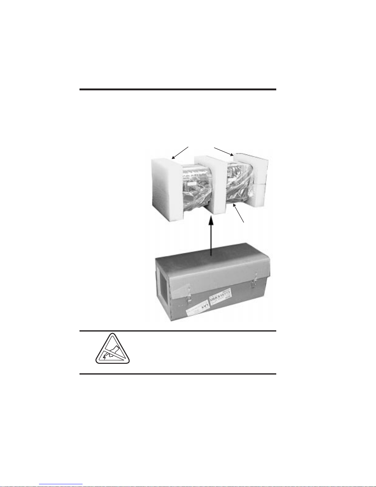
Unpacking
Privilege Card
Printers
Packing Materials
Supply Kit:
Supply Kit:
• Printer Cable
• Printer Cable
• Power Cord
• Power Cord
• Manuals
• Manuals
• Card Weight
• Card Weight
• Card Catcher
• Card Catcher
• Software (P500)
• Software (P500)
Printers ship in a carton and protective bag.
Keep all packing material in case the need to
move or reship the printer arises.Avoidtouchingtheelectricalconnectorstoprevent electrostatic discharge damage while setting up the
printer.
Foam End
Foam End
Cushons
Cushons
Printer in
Printer in
Shipping Bag
Shipping Bag
4
Thedischargeof electrostaticenergythat accumulates on the surface of the human body or
other surfaces can damage or destroy the
print head or other electronic components
used in this device.
980179-001 Rev. A
Page 13

Getting Started
When unpacking the Privilege card printer
(and card media), be aware that a clean and
nearly dust free environment is required for
properoperation andstorage.Theprintquality
can be effected by dust, body oils and acids
(i.e., finger prints) and exposure to other foreignmaterialsduringunpacking orhandlingof
the printer and media.
Check List Your PrivilegeCard Printershipswiththeitems
listed below:
• Printer (Check for proper Model):
• Interface Cable
• Power Cord
980179-001 Rev. A 5
Page 14

Getting Started
• Card Feeder Weight
• Card Catcher
• Manuals:
- Printer User’s Guide
• Software
• CD-ROM
- WindCard Software
- Windows Driver(s)
Ifanyitems aremissing,contact yourdealerfor
replacement parts.
6
980179-001 Rev. A
Page 15
Getting Started
Cardmedia,ribbon, andsuppliesare available
from yourEltrondistributororcallELTRONat
(800) 344-4003 for the distributor nearest
you.Refer toAppendixBforcompletesupplies
ordering information.
Installation The following sections serve as a guide to
printer,WindCard™software,andWindows™
card printer driver installations.
Step Ê
Unpacking
Step Ë
Attach Power
Figure 1-1
Printer
Rear Panel
With help from another person, remove the
printer from the carton and protective plastic
bag.
AC power supplied to Privilege card printers
must be current limited to 16-amps or less using an associated circuit breaker or other such
electrical device.
Place the printer in a clean, dust free loca-
tion that allows easy access to all sides of the
printer. Never operate the printer while it rests
on a side or upside down.
Set the AC power switch to the OFF (0) position.
980179-001 Rev. A 7
AC Power Switch:
AC Power Switch:
1 = ON
1 = ON
O = OFF
O = OFF
Page 16

Getting Started
Power Switch
Connection
Figure 1-2
Positions
Switch OFF Switch ON
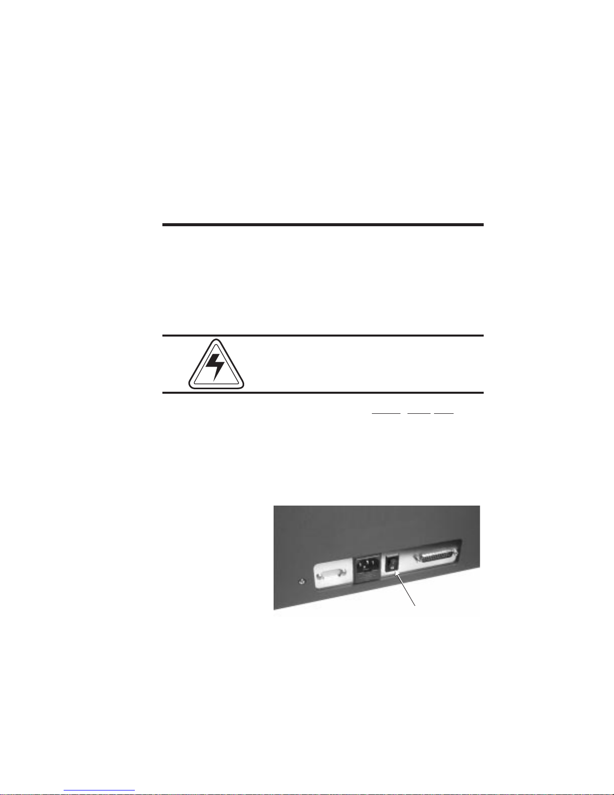
Never operate the printer in a location where
the operator, computer, or printer can get wet.
Personal injury could result.
Attach the AC power cord to the AC power receptacle in the rear of the printer.
Figure 1-3
Power
Attach the AC power cord to a grounded electricaloutlet ofthe propervoltageandplugtype.
Figure 1-4
AC Outlet
Connection
8
980179-001 Rev. A
Page 17
Getting Started
Step Ì
Attach Interface
Cable
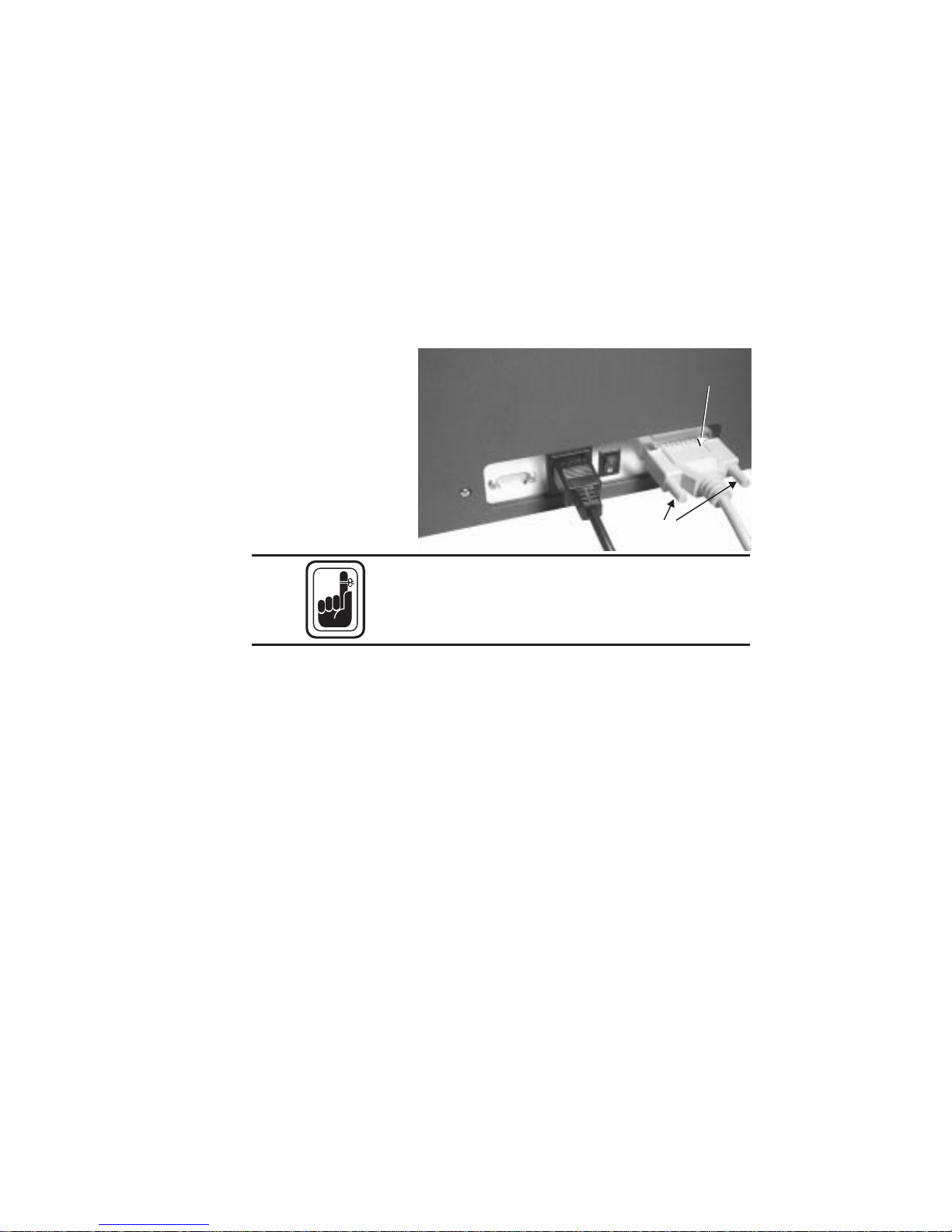
Figure 1-5
Interface
Cable
Attachandsecurethesupplied DB-25 (female)
to DB-25 (male) parallel printer cable between
the parallel port of the host computer and the
parallel interface connector on the back of the
printer.
Interface
Interface
Cable
Cable
Secure
Secure
Connector
Connector
Intermittent or unpredictable operationmay
occur from unsecured connectors.
See Appendixes A and B for cable specifications and ordering information.
Step Í
Applying Power
Setthepowerswitchto ON (1). Notethatmessagesappearon the LCDscreensasthe printer
cycles through the power-on sequence. Also
note that READY appears at the end of the sequence. If theseeventseitherfailtooccuror an
ERROR message appears instead of READY,
refer to Appendix A - Trouble Shooting.
980179-001 Rev. A 9
Page 18

Getting Started
Step Î
Windows™ 3.1
Software
Installation
Startthehostcomputer.AfterDOShasloaded,
start Windows™. Insert the WindCard™ diskette into a floppy disk drive. From the Windows™ Program Manager‘s File pull-down
menu, select R
un....
Enter A:SETUP (or B:SETUP if you placed
the diskette in drive B). Press the Enter key.
10
Follow the installation instructions on the
screen to install the software.
Refer to Section 2, Operation, for information
on loading cards and ribbons and for initializing the printer for operation.
980179-001 Rev. A
Page 19

Getting Started
See Appendix C for loading WindCard™ software into other operating platforms and the
Windows™ Printer Driver file.
980179-001 Rev. A 11
Page 20

Getting Started
12 980179-001 Rev. A
Page 21

Getting Started
Upgrading to
Expanded Memory
Users can field upgrade P500 printers to include ExpandedMemory.P600salreadyhave
thismemory.Onlythe CPUboardofModule 1
(the Print Station board) exhibits improved
performance with the Expanded Memory installed. The Memory Extension Board plugs
intotheCPU boardof Module 1. Accesstothis
board requires removal of the rearprintercase
assembly.
Avoid unnecessary risks! Removal of the
RearCase ofthe printerexposes CircuitBoards
thatcontainalithium batteries. These batteries
operate for long periods of time and, replacements may never become necessary. Anyone
replacing these batteries subjects his or herself
to the following risk:
WARNING:
• A Danger of Explosion exists if a
battery is incorrectly replaced.
• Replace only with the same or
equivalent type recommended by the
manufacturer.
• Dispose of used batteries according
to the manufacturer’s instructions.
980179-001 Rev. A 13
Case removal exposes circuit points that, if
touched with power on, can present a hazard.
Therefore, never remove any case
component without first unplugging the
Power Cord.
Page 22
Getting Started
Case Removal
Step 
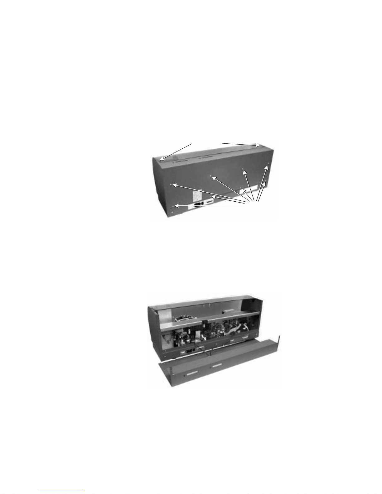
Figure 1-6
Screws Holding Rear
Case
Case Removal
Step ·
Using a one-millimeter Allen wrench, remove
the two screws holding the top of the case.
Then, using amediumPhillipsscrewdriver,remove the eight screws that secure the back of
the case.
Remove Allen
Remove Allen
Screws
Screws
Remove
Remove
Philips
Philips
Screws
Screws
Without letting the rear case move backward
fromitspositionwhilesecured, lifttherear case
straight up. Wires attached to the switches and
LCDs restrict how far the rear case can separate from the printer. Therefore, after freeing
therearcasefrom the printer,resttherear case
at a position that does not stress the wires.
Figure 1-7
Rear Case Removed
14
980179-001 Rev. A
Page 23

Getting Started
Case Removal
Step 3
Figure 1-8
Bracket Removal
Expanded Memory
Board Installation
Removal of the upper Phillips screws frees a
bracket. First note the proper position of this
bracket, and then remove the bracket. If
replaced improperly, the rear case screws cannot be refastened.
The addition of an Expanded Memory board
in Module 1 of a P500 allows the host computer to download all image data in a continuous stream, instead of the single color
downloadsfollowed byassociated printingthat
occur without this addition. Multiple-card
printing occurs much faster with this option installed. Rear case removal gives access for this
upgrade.
980179-001 Rev. A 15
Before touching any of the circuit components
on either the printer or the Expanded Memory
board,be sureto dischargeany staticchargeby
touching the metal chassis. Better yet, wear a
grounding wrist band.
Page 24

Getting Started
Installing the
Memory Board
Step 
Figure 1-9
Expanded Memory
Installation
Plug the Expanded Memory Board into the
two connectors on the upper right section of
theCPU boardof Module1. Matchtheconnectorssuchthat the ExpandedMemoryboardremains confined within the boundaries of the
CPU board, not oriented to extend over the
edge.
Installing the
Memory Board
Step ·
16
Replacethebracketand printer casebyreversing the steps performed during their removal.
980179-001 Rev. A
Page 25
2
Operation
This section contains information on the operation of the Privilege card printer.
Major
Components
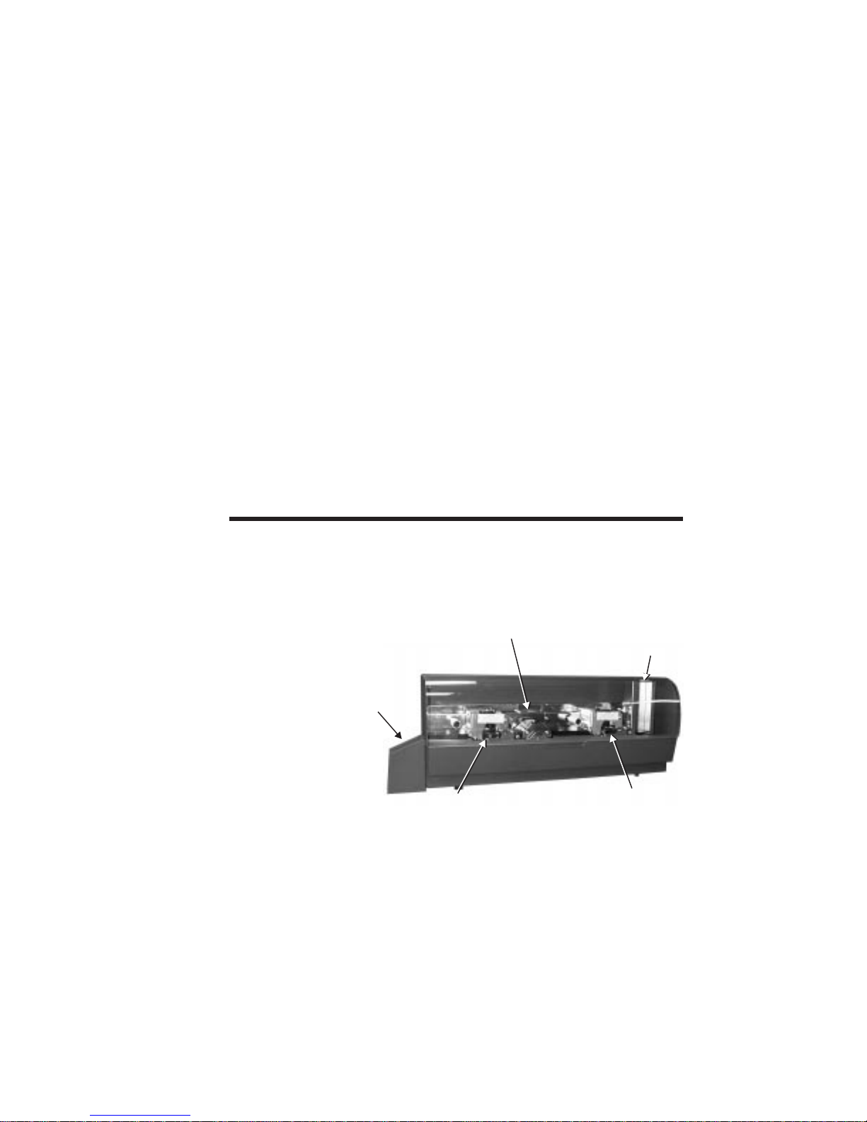
Figure 2-1 shows a P600 Card Printer. Note
that both models have similar
appearances—except,the P500hasaLaminatorwhere theP600 hasasecondPrintStation.
Card-Feed
Figure 2-1
Card-Flip
Major Components
Card
Card
Catcher
Catcher
Print or
Print or
Lamination
Lamination
Station
Station
980179-001 Rev. A 17
Card-Feed
Hopper
Hopper
Print
Print
Station
Station
Page 26
Operation
Controls &
Indicators
The Power
Switch
Figure 2-2
Printer Controls
and Indicators
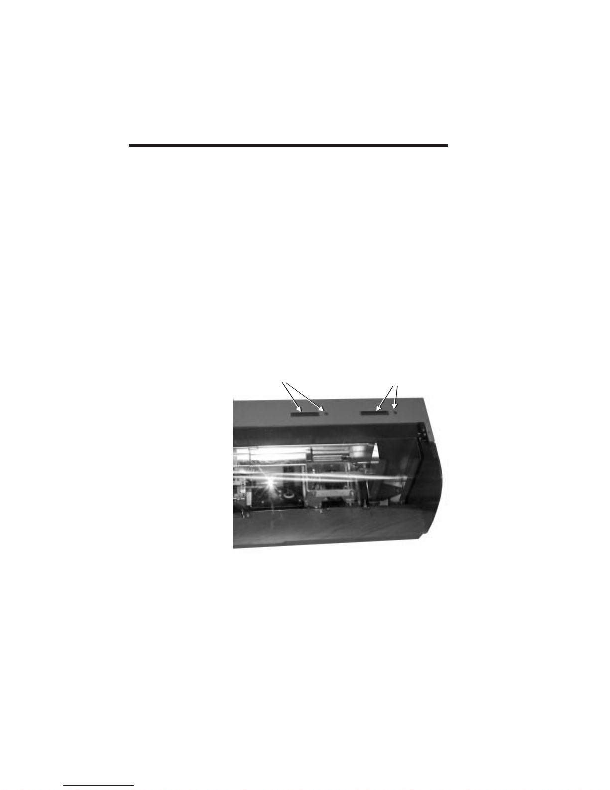
All the card printer controls and indicators, except for the power switch, reside on the top of
the printer.
The POWER SWITCH is located on back
panel of the printer. Placing the switch in the
ON (1) position applies power to the printer.
Placingtheswitchin the OFF(0)positionturns
off the printer. See Figures 1-1 and 1-2 in Section 1.
The POWER SWITCH also works in conjunction with the Panel Button. See the
Panel Button on the following pages.
Module-2 LCD
Module-2 LCD
and Button
and Button
Module-1 LCD
Module-1 LCD
and Button
and Button
18 980179-001 Rev. A
The following LCD messages can appear:
Page 27

Operation
REPORTING LCD
LCD MESSAGES DESCRIPTIONS
Module 1 Print
Station
Module 2 Print
Station (P600)
INITIALIZING Printer Initializing • • •
WARMING UP P500 Laminator Wait •
READY Ready to Print • • •
PRINTING Printing in Progress • •
LAMINATING Lamination in Progress •
OUT OF RIBBON New Ribbon Required • • •
OUT OF CARD More Cards Required • • •
COMMAND ERROR Command/Parameter Error • • •
MECHANICAL ERROR Mechanical Problem • • •
ENCODING ERROR Read Verify Error • •
READING ERROR Error Reading Mag.Stripe • •
ROTATION ERROR Card-Flip Error •
TEMPERATURE ERROR Laminator Temp. Wait •
COVER OPEN To Proceed, Close Cover • • •
Module 2 Lami-
nation Station
980179-001 Rev. A 19
See Appendix A for troubleshooting tips.
Page 28

Operation
Ribbon
Preparation
Figure 2-3
Ribbon and
Empty Core
Ribbon
Preparation
Step 1
Ribbon
Preparation
Step 2
Both the Print Stations and the P500 Lamination Station require the same pre-installation
ribbon preparations. To prepare a ribbon, the
taped end must be refastened to an empty
core. Eltron recommends the following:
Lamination
Print
Place both the ribbon and an empty core on
end, next to one another, and touching. For
Lamination ribbons, the notched end of the
empty core must face up.
Untape the end that fastens the ribbon end to
the roll while leaving the tape attached on the
supply side.
20
Ribbon
Preparation
Step 3
Figure 2-4
Ribbon
Preparation
Unwind enough ribbon to reach the empty
coreandtapetheend down. If boththeribbon
rollandthe emptycoreare kept touchingwhile
the tape is refastened, ribbon should be centered on thecore.Animproperlypreparedribboncanresultin wrinkling in theprinterduring
ribbon advances.
980179-001 Rev. A
Page 29

Operation
Ribbon
Preparation
Wind one or two turns of ribbon onto the ribbon core.
Step 4
Ribbon Loading Ribbon loading involves the placement of the
prepared ribbon onto the Supply and Take-up
spindles.Similarprocedures applytoPrint Stations and Laminators, as follows:
Ribbon Loading
Lift open the cover.
Step 1
Figure 2-5
Raising the Cover
Ribbon Loading
Step 2
Press down on the Print/Lamination Head Release Latch to raise the Print Head. The Print
Head springs upward when released.
Press Here
Figure 2-6
Raising the Print
Press Here
to Raise
to Raise
Print Head
Print Head
Head
980179-001 Rev. A 21
Page 30
Operation
DO NOT TOUCH the Print Head or nearby
electronic components. Discharged electrostatic energy from a person’s body or from
equipment can damage or destroy print heads
and other printer components.
Atthis pointconsider interruptingribbon installation to perform a cleaning, as described further on in this section. At the very least, wash
off any buildup on the Cleaning Rollers.
Ribbon Loading
Step 3
Using a prepared ribbon, unroll a comfortable
amount from the supply side to span the distance between the Supply and Take Up spindles. Then, at the same time, slide the Supply
and Take Up Cores onto their respective spindles.
Make suretopushbothfullyontothespindles.
Also make very sure that the ribbon comes off
ofthetop oftheSupply Spindleandfeeds onto
the top of the Take Up Spindle.
Note that for proper seating the take-up
cores of Lamination Ribbons have a slot
that must align with a screw on the takeup spindle.
Take extra care when installing a Print Station
ribbon. Printing with a reversed ribbon can
damage the Print Head or make an extensive
cleaning necessary.
22
980179-001 Rev. A
Page 31

Figure 2-7
Laminator Take Up
Ribbon Core
Alignment
Align Notch with
Align Notch with
Spindle Screw
Spindle Screw
Operation
Ribbon Loading
Step 4
Figure 2-8
Ribbon Path
Push down the Latch-Down lever until an
audible click occurs at the latched-down
position.
Supply
Supply
Take Up
Take Up
Spindle
Spindle
Spindle
Spindle
980179-001 Rev. A 23
Page 32

Operation
Figure 2-9
Latching Down
Print Head
Press Here to
Press Here to
Latch Down
Latch Down
Print Head
Print Head
24 980179-001 Rev. A
Page 33

Operation
Ribbon Loading
Step 5
Initialize ribbon—after changing or replacing
ribbons or following a Mechanical Error. Use
the button closest to the Station getting new
ribbon or reporting an error. To initialize:
Color Ribbon-Press andholdthe PanelButton until ribbon advances. Ribbon should stop
with the Print Head between a clear and a yellow panel.
Black Plus Overlay Ribbon - Press and
hold the Panel Button until the ribbon advances.The ribbonshould stopwith anoverlay
panel centered at the print head.
Monochrome Ribbon - No initialization required.
Hologram Ribbon - No initialization required for ribbons that have no hologram
placement requirements and no index marks.
P500 Lamination Ribbon - Press and hold
the left panel button until ribbon advances.
Only ribbons with die-cut panels require Initialization. Ribbon should stop with a black indexmarklocated totheright oftheLamination
Head.
980179-001 Rev. A 25
Handling
the Media
Maintain a clean and nearly dust free environment in media storage areas. Dust, body oils
and acids (e.g., finger prints) and other foreign
materials encountered while unpacking or
handling of the printer and media can have an
adverse affect on card images.
Page 34

Operation
Cards just removed from the media packaging
typically have accumulated an electrostatic
charge. Electrostatic charges can cause cards
to stick together, making card feeds difficult.
Card shuffling can reduce some of this adhesive force. However, avoid bending the card
mediaortouchingthecard surfacesthat willreceive images.
DO NOT set unprinted cards on dust or lint
carrying surfaces, i.e., table tops, cloth, computers, etc..
DO NOT place media with magnetic stripes
on or near magnetic sources, such as: monitors, non-electronic phones, paper clip holders, speakers, etc.
26
Card Gate
Adjustment
The Card Gate serves to meter card feeds so
that onlyonecardfeedsata time. If more than
one card feeds, a card jam occurs. Each card
thickness requires a different Card Gate opening. Never intermix cards with different thickness in the Card Feed Hopper. Only use
0.030-mil cards in P500s
980179-001 Rev. A
Page 35

Figure 2-10
Card Hopper
Card
Card
Weight
Weight
Cards
Card Gate
Card Gate
Adjustment
Adjustment
Card Feed
Card Feed
Rollers
Rollers
Operation
Card Feed
Card Feed
Opening
Opening
Prevent Media Jams!
Adjusting the Card Feeder is critical for proper
mechanical operation of the printer.
980179-001 Rev. A 27
Page 36

Operation
Card Gate
Adjustment and
Media Loading
Step 1
Figure 2-11
Card Gate
Adjustment
Placeasinglecard of the desiredthicknessinto
theCardFeeder. OpentheCardGate(turn the
gate adjustment knob clockwise) until the end
of the card can fit under the gate.
Gate too High
Gate too Low
28
Gate About Right
980179-001 Rev. A
Page 37

Operation
Card Gate
Adjustment and
Media Loading
Step 2
Card Gate
Adjustment and
Media Loading
Step 3
Card Gate
Adjustment and
Media Loading
Step 4
With asinglecardendjustunderthe gate, turn
theadjustment knobcounterclockwisetolower
the gate to the point the gate just contacts the
card. Note that any further lowering pivots the
otherendofthecard off of the rightfeedroller.
Turn the knob clockwise a quarter turn to add
some space between the gate and the card.
Placeasecondcardon top of the first.Without
bending or deforming the cards, try to slide
both cards through the gate, If only the lower
card fits, the adjustment should suffice. If both
cards fit under the gate, either lower the gate
slightly or repeat the previous steps.
Add cards of the same thickness to the Card
Feed hopper sufficient for the printing needs
and place the Card Weight on top of the stack.
During the first few print cycles, watch for card
jams or feed failures. Alternately, send a Card
Feed command to check for proper feeds, as
follows:
From the Windows Driver (See Appendix C),
type:
ME↵
where:
↵ = Enter
From WindCard (See WindCard manual), Select Printer Tools. In the Printer Tools dialog
box Enter:
ME↵
980179-001 Rev. A 29
Page 38

Operation
Printer
Access and
Usage
The printer requires at least three (3) inches of
free space around all sides for access to printer
controls, card input, and card output.
Do Not Operate Printer with Cover
Open.
To maintain a clean printing environment and
to prevent ESD damage, keep the cover of the
printer closed except during maintenance and
media loading procedures. An interlock prevents card flips with the cover open.
With a fixed amount of space available, the
maximum number of cards the Card Feed
hopper can hold varies as a function of card
thickness, as follows:
• 100 of the 30-mil (0.762 mm) cards
• 150 of the 20-mil (0.508 mm) cards
Note that P500s can only laminate 30-mil
cards.
30
980179-001 Rev. A
Page 39

The Card Catcher tray begins spilling cards
onto the surface below after collecting the following:
• 50 of the 30-mil (0.762 mm) cards
• 75 of the 20-mil (0.508 mm) cards
Figure 2-12
Card Catcher
Tray
Printing When theribbonandcardmedia areloadedas
previously described, and the printer power is
on, the card printer is ready to print.
Operation
Printing requires the WindCard™software, (a
Windows™softwareprogram),theWindows™
printer driver, or direct printer command level
programming through the printer interface.
980179-001 Rev. A 31
Page 40

Operation
Printing a Test
Card
Figure 2-13
Color Printer
Test Card
The printerprintsaTestCardiftheRight
(Module 1) Panel Button is pressed and
held in while printer power is turned on. The
button can be released when SELF TEST appears on the LCD. Remember to synchronize
the ribbon for any color printing.
P500s print and then laminate. The informa-
tionthatappearsonthe cardappliesto Module
1.P600sprintonbothsides—eachmoduleimages a different surface. Module 1 information
appears on one side, and Module 2 information appears on the other.
P500 Print Sta-
P500 Print Sta-
tion Test Card
tion Test Card
P500 Lamination
P500 Lamination
Station Test Card
Station Test Card
P600 Station
P600 Station
Test Card
Test Card
Adjustments The card printers have no user adjustable fea-
32
tures except for the card gate adjustment, see
preceding pages.
980179-001 Rev. A
Page 41

Operation
Protect Your Factory Warranty!
Neglect in performing recommended cleaning
procedures canvoidyourwarranty,ascanimproper packaging and shipping.
Other than the recommended cleaning procedures described in this manual, only allow
Eltronfactoryauthorizedtechnicians to service
Privilege printers.
NEVER loosen,tighten,adjust,bend, etc. any
part or cable inside the printer.
The only user adjustable features of the Privilegecardprinters are madeinsoftware (orprogramming) and the card feeder gate
adjustment.
Physical Processes A sensor signals when the feederrollersdeliver
a card to the card transport rollers. Cleaning
Rollers remove dust or lint, and transport rollers accurately position the cards for printing,
lamination (P500), Smart Card Contact Station docking (optional), and magnetic stripe
encoding (also optional).
980179-001 Rev. A 33
The print and laminator head(s) lower to the
surface of the card for printing or lamination.
Printing occurs with ribbon movement and
card movement synchronized. After the completion of operations at one station, cards
moveon tothe nextstation.Cardsejectafterall
specified card operations have occurred.
Page 42

Operation
Color Dye
Sublimation
Gray-Scale Dye
Sublimation
Resin Thermal
Transfer
Color imaging involves three passes of cards
underaprinthead.Yellow, magenta,and cyan
dyes diffusefromcorrespondingribbonpanels
onto the cards in measured quantities for each
dotofa300dpi matrix. Each ribbonpanelcan
produce 32 dye densities on a dot-by-dot basis. Therefore, the range of colors for each dot
is 32.7K.
Gray scale imaging involves a single pass of
cards under the print head. Measured quantities of black dye diffuse from the ribbon onto
the cards on a dot-by-dot basis. Each card dot
can have 32 different densities.
Monochrome ribbons and the monochrome
panels of multiple-panelribbonsproducesolid
imaging by transferring a very durable resin
material onto cards. Resin either transfers or
not on a dot-by-dot basis. Unlike dye sublimation,noin-betweenconditionsexisttoproduce
a gray scale within each dot. Particularly Bar
Codes,but alsoText, Lines,and Rectanglesoften get composed using solid images. Also
Thermal Transfer ribbons come in a variety of
colors other than black. However, bar code
readers need black bar codes.
Overlay Varnish
Thermal Transfer
34
Ribbons with Dye Sublimation panel(s) typically also have an Overlay Varnish Thermal
Transfer panel. These include YMCKrO,
YMCKrOKr, and KsO ribbons. Both color and
gray-scale dyes fade withexposuretoultravioletradiation.Acoating of overlayvarnishgives
images a much longer life. Notably, only dye
sublimation images require this protection.
Resin images hold their color without the protection of overlay varnish. P500 Overlaminate
ribbons with die-cut patches or transfer mate-
980179-001 Rev. A
Page 43

Operation
rial also deposit a card coating that adds ultraviolet protection and an even longer card life
than overlay varnish.
Print Sequence For P500 printers without Expanded Memory,
the typical print sequence for YMCKrO Ribbons proceeds as follows:
• Printerribbonsynchronizes totheyellow(Y)
ribbon panel prior to printing. If not, press
the RESET button to re-synchronize.
• Card-feed rollers deliver a card to the transport rollers, which accurately position cards
for all subsequent printer operations.
• Data for Yellow (Y) imaging downloads.
• Yellow Printing occurs.
• Card moves back, and ribbon advances to
next panel.
• Download, print, return card, and synchronize steps occur for ribbon panels Magenta
(M), Cyan (C), Black Resin and Overlay.
• For duplex (two-sided) card printing, cards
move to the card-flip, where the lower side
transfers to an up-facing side. P500 cards
return againtothe print headofthefirst station for a repeat of the imaging sequence.
Often, only black resin (say for a bar code)
gets applied on the second side. The
YMCKrOKr ribbon offers an economical
choice for those with this requirement.
• After imaging, P500s send the cards to the
Laminator station through the Card-Flip.
There, either a diecutpatchoralamination
material is applied to the up-facing side.
P500s only support single-side lamination
using the included software. However, the
980179-001 Rev. A 35
Page 44

Operation
Card-Flip can present either side to the
Laminator.
• When these processes end, along with any
Smart Card programming or Magnetic
Stripe encoding, a card ejects.
Data downloading is the only difference between a P500 with Expanded Memory and
one without. The extra memory makes possiblereceptionofanuninterruptedstring of data
commands prior to any imaging. With all necessary data resident in printer memory, imagingspeedincreases.Asignificant improvement
occurs for multiple copy printing.
Becauseoftheirdualprintstations,P600soffer
a great deal of versatility in choosing their operations. Users should explore the possibilities
by selecting the command sequence that best
suits their requirements. After mapping out
planned imaging, decide which ribbons best
suit these requirements. Then, decide where
the ribbons should be installed for best performance. Finally, refer to the Programmer’s
manual for commands that implement the desired operation. Remember to integrate any
Smart Card docking or magnetic stripe encoding into the command sequence.
36
980179-001 Rev. A
Page 45

Operation
Cleaning The
Printer
For quality card images keep the printer dust
and lint free. Any particles left on mechanisms
inthecardpathcan migrate onto cardsandinterfere with both YMC dye sublimation and
resin thermal transfer. These ribbon materials
cannot penetrate particles left on the cards.
Thefrequencyofcleaning requiredvaries,depending on the print environment and the usage.
Never use a shop air compressor to blow
away particles in the printer. Air compres-
sors can contain rust-inhibiting oil and may
have ineffective moisture traps. Oil and moisture adversely affect print quality, and when
sprayed,mayspreadcontaminatesthroughout
the printer.
Also canned air requires a very careful usage.
Avoid directing an air stream in a way that
distributesparticlesfromareas having asignificant particle contamination.
Anyvacuum usedmusthaveitsoutflowwellfiltered and directed away from the printer.
Never attempt to vacuum particles off of the
PrintHead,asdamage to delicateimagingelements can result.
980179-001 Rev. A 37
Page 46

Operation
Eltron offers the following items for cleaning
the printer:
• Disposable, Clean Non-fibrous (foam)
swabs with alcohol filled handle for head
cleaning and suitable for roller cleaning
• An alcohol filled, felt pen suitable for roller
cleaning
Bend to Break
Bend to Break
and Release Fluid
and Release Fluid
• A Cleaning Kit comprised of a spray can of
alcoholand apackage ofcleaning cardssuitable for a general cleaning but required for
Magnetic Encoder head cleaning.
38
Cleaningproductsfor the Privilegecardprinter
areavailabledirectlyfrom your Eltrondistributor or call Eltron at (800) 344-4003 for the
distributor nearest you.
980179-001 Rev. A
Page 47

Operation
Alternate cleaning materials can include the
following:
• Foam swabs (never use cotton or any other
fibrous material.)
• 99% pure or better Isopropyl Alcohol for
moistening swabs
• Clean Running Water (Used for Upper
Cleaning Roller only).
Card Path
Elements
Figure 2-14
Media Path
The following figure shows the elements in the
cardpaththatrequire a periodic cleaning.Procedures follow for the following items:
• Card Guides, Smart Card Contact Station,
and Magnetic Encoder Read-Write heads.
• Card Feed Roller
• Cleaning Rollers
• Print Head
• Transport and Platen Rollers
Card Input Hopper
Card Feed
Cleaning
Rollers
Ribbon
Supply
Rollers
Card-Flip
Assembly
Magnetic
Encoder
(Option)
To Module 2
Card Flip
Card
Path
Shroud
Card
Catcher
Ribbon
Take Up
Transport
and Platen
Rollers
Print Head
PeelBar
Smart Card
Station
(Option)
Module 1
Laminator (P500) or
Print Station (P600)
980179-001 Rev. A 39
Card
Cooling
(P500)
Head Up/Down
Cam (2 places)
Module 2
Card-
Flip
Rollers
Page 48

Operation
When To Clean Cleaning frequency varies with different envi-
ronments. Typically, cleanings that follow ribbon depletion keep the card printer operating
properly. Ifnot,considereitheranotherprinter
location or a more frequent cleaning.
Cleaning
Stationary Card
Path Items
Using the
Cleaning Kit
Step 1
Using the
Cleaning Kit
Step 2
Using the
Cleaning Kit
Step 3
Using the
Cleaning Kit
Step 4
Items in the card path that cannot be reached
directly require a cleaning using the alcoholmoistened cards of the Cleaning Kit. Encoder
Read-Writeheads requirethis kindofcleaning.
Remove the ribbon from both the Supply and
Take Up spindles. See Ribbon Loading in this
section.
Moisten a Cleaning Card by spraying with alcohol. Saturate the card, but if alcohol drips
from the card, blot away the excess.
Place the moistened Cleaning Card in the InputTray,topped withthecard weight.Ifnecessary, adjust the Card Gate for the card
thickness. (Since this procedure calls for only
one card, you can open the gate as much as
you like.)
Send the Cleaning Card through the printer
several times without enabling printing. Dependingon thesetup, useoneofthefollowing:
40
Where:
= Space
↵ = Enter
EntryiseitherviaWindCard™ (see manual) or
The Windows Driver (see Appendix C).
980179-001 Rev. A
Page 49

Operation
The following command shuttles a Cleaning
Card from the Input Hopper to the Card
Catcher:
ME↵
For best results, shuttle a card five or more
times.
Cleaning the
Card-Feed Roller
Cleaning the
Feeder Rollers
Step 1
Cleaning the
Feeder Rollers
Step 2
Figure 2-15
Card-Feed Rollers
CardFeedRollersthatfail to grip thecardscan
impede the even delivery of cards to the transport rollers. To clean the Card-Feed Rollers,
proceed as follows:
Remove any cards from the Card Hopper.
Clean the rollers using a Swab or Cleaning
Pen. To gain access to initially unexposed areas, cycle the roller by applying the printer
power while holding the Panel Button on for
three (3) seconds (see Test Card sequence in
preceding description) Let the roller air dry for
two (2) or more minutes.
Card-Fee d
Card-Fee d
Rollers
Rollers
980179-001 Rev. A 41
Page 50

Operation
Cleaning the
Upper and Lower
Cleaning Rollers
Cleaning the
Cleaning Rollers
Step 1
Figure 2-16
Upper Cleaning
Roller
Upper
Upper
Cleaning
Cleaning
Roller
Roller
Spring
Spring
Clip
Clip
These rollers receive cards fed from the Input
Hopper and Card Flip. The upper roller has a
coating that collects any loose particles on the
surface of cards. Note that these rollers exist in
Module 1 just after the Card Feed Hopper and
in Module 2 just after the Card Flip.
Remove any cards from the printer. Open the
printer cover. To free an Upper Cleaning
Roller, gently pull the Spring Clip clear of the
Upper Cleaning Roller pin. Then, remove the
Upper Cleaning Roller.
Cleaning the
Cleaning Rollers
Step 2
42
Clean the Upper Cleaning rollers with running
water. Then allow the rollers to air dry without
resting the rubberized part on a surface.
980179-001 Rev. A
Page 51

Operation
Cleaning the
Cleaning Rollers
Step 3
Figure 2-17
Lower Cleaning
Roller
Cleaning the
Cleaning Rollers
Step 4
Use a swab or cleaning pen on the Lower
Cleaning Rollers. Cycle the rollers by applying
the printer power while holding the Panel Button on for three (3) seconds to expose initially
unexposed areas. This is the Test Card sequence described in Controls and Indicators,
Section 2.
Reinstall the Upper Cleaning Roller. First slide
the shaft pin into the hole in the chassis opposite the Spring Tab.
DO NOT
touchtherollersurfacethat contacts
the media.
Snaptheoppositeshaftpinoftherollerinto the
hole on the Spring Tab.
Without touching the body of the roller, make
suretherollerlocksin place.Toavoidcontamination, always hold the roller by the metal
ends.
980179-001 Rev. A 43
Page 52

Operation
Print Head
Cleaning
Print Head
Cleaning
Step 1
During printing, the ribbon(s) isolate the Print
Head(s) from the cards. Therefore, the ribbon
has the greatest influence on Print Head contamination. An improperly installed ribbon,
with thedyeandresincoatingsfacing the Print
Head can cause permanent damage. No
amount of cleaning can remove dye or resin
fused onto delicate Print Head elements.
Turn the printer power OFF. Open the cover,
raise the print head, and remove the ribbon
from both spindles. See Ribbon Loading, in
this Section.
The print head should only be cleaned with a
solution of 99% pure Isopropyl Alcohol and a
clean non-fibrous (foam) swab.
Avoid touching the Print Head elements. The
release of Static charges can damage the Print
Head elements and Internal circuits.
44 980179-001 Rev. A
Page 53

Operation
Print Head
Cleaning
Step 2
Figure 2-18
Cleaning
Print Head
Gently rub an alcohol-moistened swab across
the print head from the front to the back of the
printer. Do Not Soak the Print Head.
Allowtheprintheadto dryfor 2minutesbefore
reloading the ribbon and core.
Initiate a Test Card sequence. See Printing a
Test Card in this section.
Cleaning the
Transport and
Platen Rollers
Cleaning Platen
and Transport
Rollers
Step 1
980179-001 Rev. A 45
Along with the Cleaning Rollers, these rollers
movethecardsbetween the InputHopperand
CardCatcher.ExceptforthePlaten, these rollers operate in pairs—a lower drive roller and
an upper pinch roller that holds cards against
the drive roller.
Open the Cover, and unlatch and raise the
Print andLaminationHeads,Removeanyribbon. Note that all associated instructions appear in previous descriptions.
Page 54

Operation
Cleaning Platen
and Transport
Rollers
Step 2
Figure 2-19
Encoder Shroud
Shroud
Shroud
Fasteners
Fasteners
Remove the Shrouds that cover the associated
transport rollers. Note that two screws hold
each Shroud in place.
In the following steps, cycle the rollers to reach
initially unexposed areas by applying the
printer power while holding the Panel Button
pressed for three (3) seconds. This is the Test
CardsequencedescribedinControls and Indicators in this section.
46
In the following steps, avoid touching the Print
Head. A static discharge can damage delicate
PrintHead elementsas wellasinternalcircuits.
980179-001 Rev. A
Page 55

Operation
Cleaning Platen
and Transport
Rollers
Step Ì
Figure 2-20
Encoder Transport
Rollers
Encoder
Encoder
Rollers
Rollers
Cleaning Platen
and Transport
Rollers
Step Í
Using an alcohol-moistened Swab or a Felt
Pen, clean the two sets of rollers exposed with
removal of the Shrouds. Note that these appear under both Shrouds in P600s.
Using an alcohol-moistened Swab, clean the
Cooling Station Roller (P500 only).
Figure 2-21
Cooling Station
Rollers
Cooling
Cooling
Station
Station
Rollers
Rollers
980179-001 Rev. A 47
Page 56

Operation
Cleaning Platen
and Transport
Rollers Step Î
Figure 2-22
Platen Roller
Cleaning Platen
and Transport
Rollers
Step Ï
Using an alcohol-moistened Swab, clean the
Platen Roller.
Using an alcohol-moistened Swab, clean the
roller pair under the Print Head
Figure 2-23
Print Station Rollers
Print
Print
Station
Station
Rollers
Rollers
48
980179-001 Rev. A
Page 57

Operation
Cleaning Platen
and Transport
Rollers
Step Ð
Figure 2-24
Card-Flip Rollers
Card-Flip
Card-Flip
Rollers
Rollers
Cleaning Platen
and Transport
Rollers
Step Ñ
Using an Alcohol-moistened Swab, clean the
Card-Flip Rollers.
Replace the Encoder Shroud (see Step 2), install,Ribbon,placecardsin theInputTray,and
print some Test Cards. Inspect the cards for
Print Anomalies. If Anomalies appear, refer to
Appendix A, Troubleshooting.
Cleaning
Laminator Rollers
Cleaning
Laminator Rollers
Step Ê
980179-001 Rev. A 49
The Lamination head has two rollers—an upper heated roller and a lower pressure roller.
Turn off power, open the cover, and unlatch
andraisetheLaminator head. Thisissimilarto
the Ribbon Loading described in Section 1.
Page 58

Operation
Afterturningoffpower,waitaboutfiveminutes
before cleaning the Laminator rollers. The upper Laminator roller generates a substantial
amount of heat with power switched on.
Cleaning
Laminator Rollers
Step Ë
Figure 2-25
Laminator Rollers
Upper Roller
Lower Rolle r
Using an alcohol-moistened swab, clean both
Laminator rollers. The upper roller can be
turned manually to reach initially unexposed
areas. The lower roller can be turned using the
sameprocedure thatproduces testcards. (Turn
on power while hold in the Laminator button
for three seconds) Immediately turn off power
to avoid heating the upper roller.
50
980179-001 Rev. A
Page 59

3
Magnetic Card Stripe Encoder
This section has information on the additional
operation and maintenance requirements of
an Eltron Privilege Series card printer with an
optionalMagneticCardStripeEncoder. Eltron
offers models for recording on either low- or
high-coercivity magnetic card stripes.
Introduction The general operation of a printer with an en-
coder option nearly duplicates that of models
without this option. P600 Encoders can reside
ineitherModule1orModule2, justpastaPrint
Station. P500 Encoders always reside in Module 1. Encoder installations exist for either upor down-facing magneticstripesinbothP500s
and P600s.
Only use cards with flush magnetic stripes.
Never use pasted-on stripes.
980179-001 Rev. A 51
Page 60

Magnetic Card Stripe Encoder
Media Loading
Orientation
Figure 3-1
Magnetic Stripe
Position
PrinterswithMagneticEncoderscan havetheir
read/write heads positioned either above or
below the path traveled by the cards. All
configurations must have the magnetic stripes
placed closest to the rear of the printer. However, check the configuration to determine
whether the magnetic stripe should face up or
face down. Improper hopper loads produce
read errors.
Position Stripe
Position Stripe
Toward Back
Toward Back
(and typically facing
(and typically facing
down, but check
down, but check
configuration)
configuration)
Ensuring Data
Reliability
52
A read verify pass is always performed on all
encoded cards to guarantee data integrity.
Either Software (WindCard™) or command
programming controls the Write and Readverify data processes.
980179-001 Rev. A
Page 61

Magnetic Card Stripe Encoder
Encoding With data downloaded, printers with Magnetic
Encoders can encode all three magnetic stripe
tracks simultaneously. Encoders also support
nonstandard track densities and bits per track.
Aftersettingread/writeparameters,downloads
to track buffers occurs, as follows:
where:
= Escape
= Space
↵ = Return
&Btrack#data↵
Initiationofsimultaneousthree-trackmagnetic
stripe encoding then occurs, as follows:
&E*↵
AProgrammer’s manualdescribes allthe com-
mands including those related to the Encoder
(see Appendix B).
The following shows three examples that enter
data. initiate encoding, and set up read/write
parameters that can be sent from either the
Windows™ driver or directly using DOS (e.g.,
COPYfilenameLPT1)orviaa TextEditor and
itsPrint facility(with PrivilegeDriverselected):
Example 1. Download Data and Encode Card:
Direct Control Windows Driver
&B1JOHN DOE↵ ~C0&B 1 JOHNDOE
&B2555-46-5389↵ ~C0&B 2 555 465389
&B34789↵ ~C0&B 3 4789
&E*↵ ~C0&E*
980179-001 Rev. A 53
Page 62

Magnetic Card Stripe Encoder
Example 2. Set Read/Write Parameters, Enter Data, Encode
Stripe, and Eject:
Command Result
&D175↵ Sets track-1density to 75 bpi
&D375↵ Sets track-3density to 75 bpi
&CDEW1a3↵ Sets to encode track 1 with5-bit
&CDER1q3↵ Sets toread 5-bit characters on track
&B112345↵ Enters 12345 intrack-1 buffer
&B254321↵ Enters 54321 intrack-2 buffer
&B309876↵ Enters 09876 intrack-3 buffer
&E*↵
ME↵ Ejects card fromprinter
characters
1
Encodes three tracksusing buffer
data, and positionscard for printing
Example 3. Reset to ANSI/ISO:
Command Result
&CDEW1A↵ Resets track-1 encodesto ANSI/ISO
&CDER1Q↵ Resets track-1 reads for ANSI/ISO
&CDEW2B↵ Resets track-2 encodesto ANSI/ISO
&CDER2R↵ Resets track-2 reads for ANSI/ISO
&CDEW3C↵ Resets track-3encodes to ANSI/ISO
&CDER3S↵ Resets track-3 readsfor ANSI/ISO
std.
std.
std.
std.
std.
std.
54 980179-001 Rev. A
Page 63

Magnetic Card Stripe Encoder
When to Clean
the Encoder
Cleaning the
Encoder
The Read/Write Head and drive rollers of the
Encoder require a periodic cleaning to maintain error-free encoding.
The encoder should be cleaned when:
• A “General Cleaning” is performed on the
printer.
• The printer’s Drive Rollers are cleaned.
• Write and Read verify process has failed on
morethanonecard. See AppendixA,Trouble Shooting.
Turn OFF printer power.
Remove all card media and both the Supply
andTakeUpspools fromtherespectiveribbon
spindles.
Use the Cleaning Kit procedure described in
Section 2.
Adjustments Privilege card printers with Magnetic Card
Stripe Encoders have no related user adjustments.
980179-001 Rev. A 55
Page 64

Magnetic Card Stripe Encoder
Protect Your Factory Warranty!
Neglect in performing recommended cleaning
procedures can lead to problems not covered
in the warranty.
Other than the recommended cleaning procedures described in this manual, only allow Eltron factory authorized technicians to service
these printers
NEVER loosen,tighten,adjust,bend, etc. any
part or cable inside of the printer.
The only user adjustable features of the Privilegecardprinters are madeinsoftware (orprogramming) and the card feeder gate
adjustment.
56 980179-001 Rev. A
Page 65

4
Smart Card Contact Station
This section contains information on the additional operations of card printers with Smart
Card contact stations.
Introduction Smart Cards (ISO7816) have built-in microcir-
cuits. Card memory can store fingerprints,
voice recognition patterns, medical records
and other such data. Printers can have docking
stations installed that can interface with Smart
Card circuits. Smart Card programming hardwareconnectstoaDB-9 connector on the rear
panel. Configurations with this option respond
to commands that position the cards at the
docking station, as follows:
980179-001 Rev. A 57
Command
MS
OS value
Allotherprinter operations remainthesame as
those for other Privilege models.
Result
Moves card to Contact
Station
introduces offset of
value dots from Station default (96)
Page 66

Smart Card Contact Station
Do not position printing over Smart Card contacts.
Media Loading
Orientation
Figure 4-1
Card Contact
Position
Orient the cardswiththeSmartCardChipfacing up and such that the edge closest to the
contacts feeds first.
Up-Facing
Up-Facing
Chip Contacts
Chip Contacts
Adjustments No adjustments exist for Privilege printers with
58
Smart Card programming stations other than
theCardFeederGateAdjustment described in
section 2.
980179-001 Rev. A
Page 67

Smart Card Contact Station
Protect Your Factory Warranty!
Neglect in performing recommended cleaning
procedures canvoidyourwarranty,ascanimproper packaging and shipping.
Other than the recommended cleaning procedures described in this manual, only allow
Eltronfactoryauthorizedtechnicians to service
these printers.
NEVER loosen,tighten,adjust,bend, etc. any
part or cable inside of the printer.
The only user adjustable features of these card
printers are made in software (or programming)andthecardfeeder gateadjustment(see
Section 2).
Smart Card
Chip Interface
When a command to the parallel printer interface sends a card to the Smart Card Programming station, the printer connects the Smart
Card Chip contacts to the female DB-9 connector on the rear of the printer. An attached
external Smart Card Programmer uses the
DB-9 as an interface to Smart Card chip connections.
Figure 4-2
Host Computer
Smart Card
Smart Card
Contacts Interface
980179-001 Rev. A 59
Smart Card
Contact
Contact
Interface
Interface
Host Computer
Interface
Interface
Page 68

Smart Card Contact Station
DB-9 Pins
Smart Card
Contact Points
1 C1 (Vcc)
2 C2 (Reset)
3
C3 (Clock)
4 C4 (RFU)
5 C5 (GND)
6 C6 (Vpp)
7 C7 (I/O)
8 C8 (RFU)
9
(GND when chip is at station)
Media Jams Always remove the bottom card of a two-card
jam first. Never pull the top card out of the
printer. Instead, sequence the printer power
with only the top card remaining (the last card
toentertheprintpath). Remove all othercards
from the path and card feeder.
60
Damagemay occurto thecontacts attheSmart
Card chip programmer station if the top (last)
card is not ejected by the printer.
980179-001 Rev. A
Page 69

Common Printing
Problems Trouble
Shooting Guide
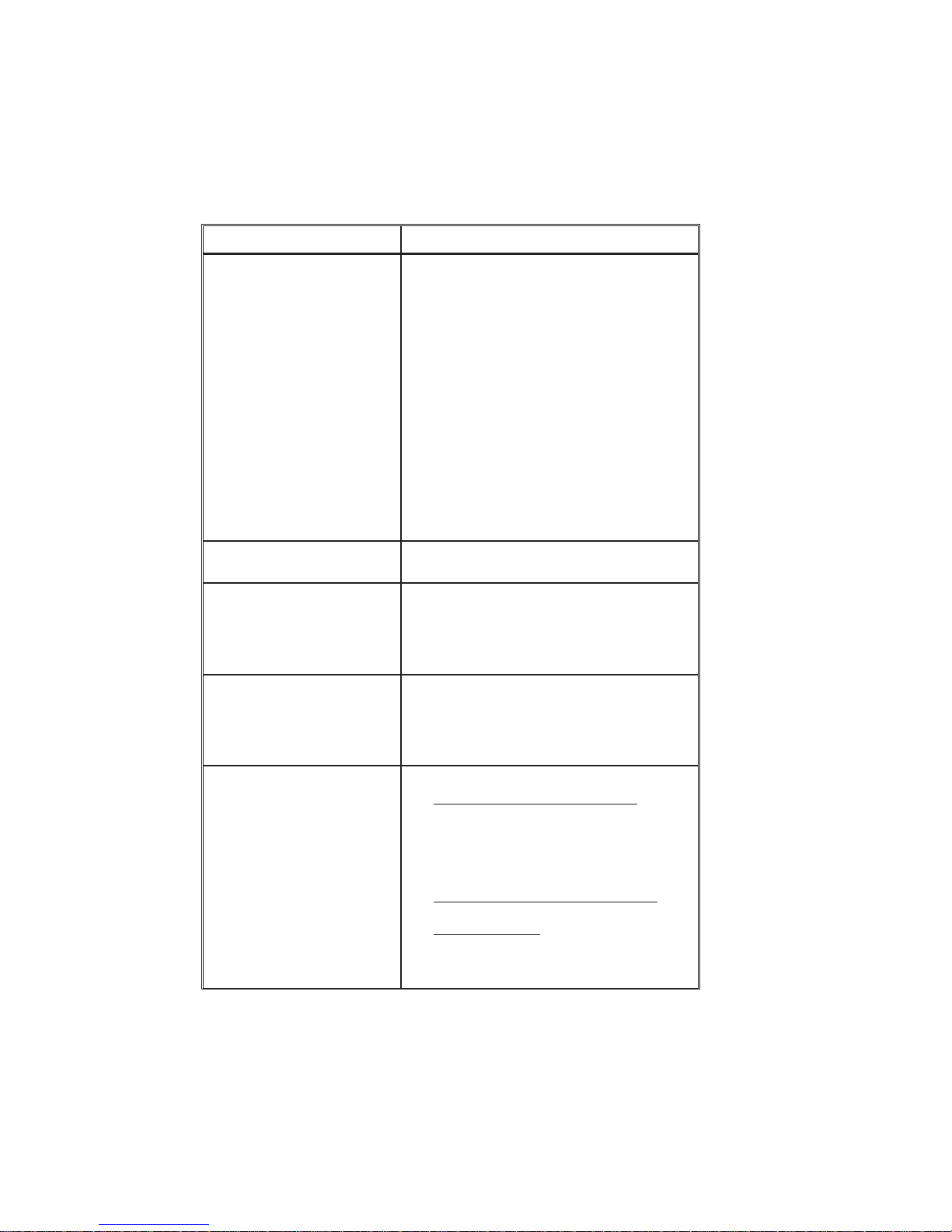
Problem Solution or Reason
Appendix A
Trouble Shooting
The following lists some common issues that
can confront users experiencing problems
when using Eltron Privilege Series card
printers.
No messages appear on LCD.
An LCD indicates WAIT
TEMPERATURE
Printing appears faded or exhibits poor quality.
Parallel “Scratch Lines”, missing image parts
1. Power Switch OFF (O position)
to ON (1 position).
2. Power Not connected
the Printer to the outlet power.
3. Tripped Breaker
panel supplying power outlet.
1. Too Cold
Head has not yet stabilized within proper
operating range.
2. Too Hot
Head has exceeded a proper operating
temperature—typically due to high volume
printing.
1. Clean the print head.
2. Adjust the contrast and intensity in software
or with programming.
3. Verify value of related Print Head Resistance does not apply to current print head.
Print a Test Card, and compare value with
label on related print head.
1. Check ribbon
2. Clean Print Head
3. Call technical support
: Associated Print or Lamination
: Associated Print or Lamination
: Check AC cord from
: Check the Fuse/Breaker
: Set switch
980179-001 Rev. A 61
Page 70
Appendix A
Problem Solution or Reason
An LCD indicates
COMMAND ERROR
An LCD indicates
OUT OF RIBBON
Cards are present, but LCD indicates
OUT OF CARD
An LCD indicates
READING ERROR
An LCD indicates
MECHANICAL ERROR
Errors Using Windows Driver:
1. Printer Command Coding Error:
Clear command error by pressing related
Panel Button.
2. Ribbon Error:
Press Panel button; note card ejects, if present, and ribbon re synchronizes
3. Feeder Error (empty):
Press Panel Button; note that last command
repeats using another card.
4. Magnetic Stripe Write Error:
Press Panel Button; note that card ejects
and command repeats with another card
5. Other Errors:
Press Panel Button; note that any card
present ejects and error indications cease
6. Check the programming command syntax.
1. Replace used ribbon.
2. Check for broken ribbon
Card Feed Problem:
1. Card Gate adjusted too low
2. Card Weight not in place.
3. Cards or Card-Feed rollers contaminated
with oily deposit and require cleaning
Encoder Command Coding Error:
1. Verify command syntax
2. Call technical support
3. Check card Hopper for proper stripe
position
Mechanical Error:
1. Card Jam - Nonmagnetic Encoder
Open cover, remove related upper cleaning
roller, empty feeder, pull jammed cards out.
Replace upper cleaning roller and run Test
Card
RESET. Cycle power off and on.
2. Card Jam - Magnetic Encoder Models
See Section 3, Clearing Media Jams.
3. Card Not Feeding
printer. Release Print Head latch and run
Test Card
RESET, Cycle power off and on.
completely through
:
:
62 980179-001 Rev. A
Page 71

Problem Solution or Reason
Appendix A
LCD indicates
COVER OPEN
Printer cuts (melts) through the
transferribbon.The ribbonisadvancing at the same rate as the
card media.
Ribbon breaks during resynchronization of the color ribbon panel.
Voids on printed card, varies
from panel to panel.
Voids on printed card, same for
all card panels
Close the cover so that card flips can occur
1. Reinstall the ribbon.
2. Synchronize the ribbon panels by pressing
the related Panel button until the ribbon
starts advancing.
3. Verify proper (or default) print settings in
software.
4. Verify the proper ribbon/panel combination
are selected in the software or programming sent to the printer.
5. Verify that the print heat (resistor) is set to
the correct level in the WindCard software,
Windows color printer driver or by programming commands sent to the printer.
Print a Test Card and note the resistance/heat setting. Verify the card values
match those that appear on the print head
label. (See following illustration.)
1. Raise the related Print Head and synchronize the ribbon. The previous print process
may have been interrupted during the print
process.
1. Clean the Cleaning Roller
2. Complete all cleaning procedures
1. Check Card surfaces for smoothness,
flatness or edge burrs If necessary, get new
cards.
2. Use approved media.
980179-001 Rev. A 63
Print Head
Print Head
Label
Label
Page 72

Appendix A
Other Support
Resources
First attempt a repair using the forgoing table,
Then, if necessary, contact the dealer that sold
you the printer.
Eltron International also offers a variety of information and user support services, as follows:
• Internet:
http://www.eltron.com
ftp://ftp.eltron.com
e-mail:
Label Printers: techsup@eltron.com
Card Printers: privsup@eltron.com
Europe: eurosup@eltron.com
Singapore: asiasup@eltron.com
Latin America: latinsup@eltron.com
• BBS: +1 (805) 579-3445
TheBBSsupports dataratesup to 28.8BPS
with No Parity, 8 data bits, and 1 stop bit
(n,8,1). Communications software should
haveanANSITerminalMode (not MS Windows Terminal) such as Q-Modem.
64
• CompuServe e-mail: 102251,1164
• Customer Service: +1 (800) 344-4003
For the name of a dealer in your area.
• Technical Support FAX:
U.S.A.: +1 (805) 579-1808
Asia: +65 73 38 206
Europe: +44 (0) 1189 895 762
Latin America: +1 (847) 584 2725
For your assistance and support with Eltron
printers and software.
980179-001 Rev. A
Page 73

Appendix A
Parallel Interface
Cable Wiring
The following diagram shows the cable wiring
required to use the printer’s parallel interface.
HOST
STROBE
DATA 0
DATA 1
DATA 2
DATA 3
DATA 4
DATA 5
DATA 6
DATA 7
ACK/
BUSY
PAPERERR.
READY
INIT
ERROR/
N/A
N/A
N/A
SIG. GND
SIG. GND
SIG. GND
SIG. GND
SIG. GND
SIG. GND
SIG. GND
DB-25
Pin No.
1
2
3
4
5
6
7
8
9
10
11
12
13
14
15
16
17
18
19
20
21
22
23
24
25
DB-25
Pin No.
1
2
3
4
5
6
7
8
9
10
11
12
13
14
15
16
17
18
19
20
21
22
23
24
25
PRINTER
STROBE
DATA 0
DATA 1
DATA 2
DATA 3
DATA 4
DATA 5
DATA 6
DATA 7
ACK/
BUSY
PAPERERR.
READY
INIT
ERROR/
N/A
N/A
N/A
SIG. GND
SIG. GND
SIG. GND
SIG. GND
SIG. GND
SIG. GND
SIG. GND
Female DB-25 to Male DB-25
Supported Card
Media and Ribbon
Thecardprinterssupportawidevariety ofcard
media and ribbon types. The card media
should be matched to the ribbon type to avoid
ribbon burning, sticking and to achieve proper
dye sublimation. For optimum performance
and printer (Print Head) life
, always use Eltron
approved card media and ribbons.
980179-001 Rev. A 65
Page 74

Appendix A
Card Media
CR-80 credit card style cards (ISO 7810)
made of PVC (recommended) or Polyester
ABScardmaterials.Somecard manufacturing
processes use a thin, clear over-lamination.
Magnetic (Mag.) Stripe Card (ISO 7811)
Smart Card with ISO 7816 Chip, With AF-
NOR Chip, or a combination of the Magnetic
Stripeononesideandoneof theChipversions
on the other side.
Ribbons Eltron Privilegecardprintersrequire Eltron ap-
proved ribbons. Eltron’s resin thermal transfer
and die sublimation media are specifically designed for Privilege card printers. (See Appendix B.)
Thermal Transfer (Resin) -Allprintstations
can use Thermal Transfer ribbon. Resin offers
more durability than dye sublimation, with
greaterresistancetoscratchesand UV-induced
fading.
66
DyeSublimation- Printingrequiresdye sublimation ribbons with either black orCyan(C),
Magenta(M)andYellow (Y)panels.Theseribbons have Overlay varnish panels to add UV
protection and durability. Color ribbons have
blackthermaltransferresin panels forbarcode
and other solid imaging.
980179-001 Rev. A
Page 75

Appendix A
Radius 0.125 in (3.18mm)
3.375 in ± 0.010 in
(85.72mm ± 0.25mm)
Card Dimensions
2.125 in
± 0.002 in
(53.98mm
± 0.05mm)
Thickness
0.009 in to 0.034 in
(0.23mm to 0.84mm)
Magnetic Stripe Dimensions
0.218 in (5.54mm) Max.
0.623 in
(15.82mm) Min.
0.000 in to 0.115 in
(0.00mm to 2.92mm)
0.000 in to 0.115 in
(0.00mm to 2.92mm)
Smart Card Chip
0.221 in (5.62mm)max. gap
0.01 in
(2.54mm)
Min. gap
(8.25mm)
980179-001 Rev. A 67
C1
0.395 in
0.210 in
(3.54mm)
No-print Area
0.790 in
21.87mm
0.782 in (19.87mm)Min.
0.403 in (10.25mm)Max.
0.631 in
(7.54mm)
0.218 in (5.54mm)Max.
0.623 in (15.82mm)Min.
C1 - VCC(Supply Voltage)
C2 - RST(Reset Signal)
C1
C4
C3 - CLK(Clock)
C5
C4 - RFU
C5 - GND(Logic Ground)
C6 - VPP(Programming Voltage)
C8
C7 - I/O(Data Input/Output)
C8 - RFU
Page 76

Appendix A
Printer Features
and Options
The Privilege card printer series are part of Eltron’s personal and industrial printer family. A
Privilege card printer prints on standard credit
card size cards. These color printers can produce images using either dye sublimation
and/orthermaltransfer(monochrome)modes.
This list only serves as a reference. Consult the
latest Data Sheet.
PRIVILEGE SERIES CARD PRINTERS
Print Resolution
• 300 dots per inch (11.8 dot per millimeter)
Printing Technology
• Monochrome - Thermal Transfer
• Color - Dye Sublimation
Print Time
• Typically3secondspercard(monochrome)
• Typically 45 seconds per card (color)
Print Speed
• 0.5 ips
Font Support
• Arial 22 Bold and Arial 28 Normal
• True Type fonts with the WindCard™ or
Windows™ compatible printer driver to access Windows™ resident fonts.
Bar Code Symbologies
• Code 39 (3 of 9)
• Interleaved 2 of 5 (I-2/5)
• Standard 2 of 5 (2/5)
• EAN 8
• EAN 13
• UPC A
• MONARCH
• Code 128 subsets B with or without Check
Digit
• Code 128 Subset C with or without Check
Digit
68
980179-001 Rev. A
Page 77

Appendix A
Card Types - ISO Format
• CR-80 - ISO 7810
• Option; Magnetic Stripe - ISO 7811
• Option: Smart Card - ISO 7816
• PVC (recommended), PVC w/Polyester
core, ABS card materials
Magnetic Encoding - Option
• 3 tracks
• 3 Media Recording Densities:
Low Coercivity, 300 Oersteds
Medium Coercivity, 2750 Oersteds
High Coercivity, 4,000 Oersteds
• Supports recording formats: ITA, ABA and
Thrift.
Smart Card - Option
• Supports ISO 7816 Smart Card standards
Card Dimensions
• Thickness -
Monochrome - 10 mil to 40 mil
(0.254 mm to 0.762 mm)
Color - 20 mil to 30 mil
(0.508 mm to 0.762 mm)
• Standard Card Thickness:
0.020" (0.508 mm)
0.024" (0.610 mm)
0.030" (0.762 mm)
• Width - 3.375" (85.6 mm) typical
• Length - 2.125" (53.98 mm) typical
Card Feeder
• Stacks up to 150, 20 mil cards
• Stacks up to 100, 30 mil cards
Power Requirements
• 100/120//230/240 VAC, 50-60 Hz
Operating Temperature-
• 40 to 104 degree Fahrenheit (mono.)
• 60 to 86 degrees Fahrenheit (color)
980179-001 Rev. A 69
Page 78

Appendix A
Dimensions-
Without Card Catcher:
• 30.5 in W x 12.5 in H x 10.1in D
(775mm W x 320mm H x 258mm D)
With Card Catcher:
• 34.6 in W x 12.5 in H x 10.1 in D
(880mm W x 320mm H x 258mm D)
Weight
Basic Unit:
• 61.7 lb (28.1 kg)
Shipping:
• 72.7 lb (32.9 kg)
70
980179-001 Rev. A
Page 79

Appendix B
Supplies and
Accessories
ContactyourEltron dealerwhenplacinganorder for any of the following:
Accessories Accessories available for the Privilege card
printerarelistedbelow. Always refertotheELTRON part number when placing an order.
Description Part Number
Card Printer ParallelInterface Cable, 6’
(DB-25 male to DB-25 female)
Windows™ Printer Driver
WindCard™ Classic Software,and Manual
User’s Manual (thisManual)
Programmers Manual
Lapel Clip CardPunch 806503-001
Video Kit (camera,video board, 5-panel
ribbon, and 100of the 30-mil PVC cards)
300055-001
205585-001
105525-004
980179-001
980081-001
104522-001
980179-001 Rev. A 71
Page 80

Appendix B
Print Ribbons The following imaging ribbons are optimized
for use in Privilege card printers.
Special Ribbons
Ribbon
Types
Monochrome Resin RibbonsÀ
Black ABS ÁÂ800015-008
Black 3Â800015-001
Red 3Â800015-002
Green 3Â800015-003
Blue 3Â800015-004
Yellow 3Â800015-005
Gold 3Â800015-006
Silver 3Â800015-007
White 3Â800015-009
Multi-panel Ribbons forColor Printers À
YMCKrO 3 5 800015-040
YMCKrOKr à 6 800015-048
KrO 3 2 800015-060
KsO 3 2 800015-050
NOTES:
À Bar Codes require Black Resin printing .
Á Black ABS ribbon only used with ABS cards.
 Monochrome ribbons have no panel separations.
à Duplex printing when resin is required on both sides.
YMC - DenotesYellow, Magenta, Cyan colored panels.
Kr - DenotesBlack Resin panel
Ks - DenotesBlack Dye Sublimation panel
O - Denotestransparent Overlay varnish.
Print Ribbons
Mono. Color
No. of
Panels
Part No.
72 980179-001 Rev. A
Description Part Number
Overlaminate Ribbons (P500)
Clear for fullcoverage (100 cards) 800015-014
Clear for SmartCard coverage (100
cards)
Clear for Mag.Stripe Card coverage (100
cards)
Holographic Overlay Varnish(P600)
Privilege Security Seal (350cards) 800015-011
800015-013
800015-012
Page 81

Card Media
Miscellaneous
Supplies
Appendix B
Only laminate 30-mil cards in P500 printers.
Description Part Number
Cards (PVC)
30 mil 800016-104
30 mil, LowCoercivity Stripe 800016-105
30 mil, HighCoercivity Stripe 800016-106
Heavy duty Cards(PVC w/Polyester Core)
30 mil 800017-101
30 mil, LowCoercivity Stripe 800017-102
30 mil, HighCoercivity Stripe 800017-103
Description
Drive Roller CleaningPens (12) 800105-001
Print Head CleaningSwabs (25) 104526-001
Take-up Ribbon Cores(10) 205581-001
ID Card LapelClips (100) 104527-001
Mag. Head CleaningKit 104531-001
Part
Number
Installable
Options
Description
Memory Expansion 104525-001
Replacement Print HeadKit 104540-001
980179-001 Rev. A 73
Part
Number
Page 82

Appendix B
74 980179-001 Rev. A
Page 83

Appendix C
Windows Card
Printer Driver
Those needingtoprintfromapplicationsother
thanWindCardmust firstinstalla printer driver
forthe cardprinter. TheCD-ROM shippedwith
the printer includes printer drivers for both
Windows 3.1 and Windows 95.
Installation of
Printer Drivers
Driver installation begins with insertion of the
CD-ROMintothe associated drive.Theexecutable file may or may not start automatically,
depending on the CD-ROM Auto Insert Notification check box setting within Windows.(See
Settings, Control Panel, System, Device Manager, CD-ROM.) If the Card Design Software
screen fails to appear within about 30 seconds
after CD insertion, a manual start can be used,
as follows:
For Windows 95:
1. Start the Windows Explorer and doubleclick on the drive letter designator for the
CD-ROM. (e.g., E:)
2. Next click on the Cdman folder.
3. Finally, double-click on the Cdman.exe
file.
980179-001 Rev. A 75
Page 84

Appendix C
For Windows 3.1:
1. Select File, Run...
2. From the Run dialog, select Browse.
3. Select the CD-ROM drive, the Cdman
folder, and double-click on Cdman.exe.
The screen that appears when the program
starts has flags for several nations and a small
button at the lower-left corner.
• Click on a flag to choose an associated lan-
guage.
• Clickonthe buttonin thelower-left cornerto
quit this software. Subsequent screens have
Back buttons that produce transitions back
toward this screen so that a quit path exists
fromany pointin theinstallationsequence.
76
980179-001 Rev. A
Page 85

Appendix C
In the screens that follow language selection,
choose the operating system (Windows 3.1 or
Windows 95), Windows Drivers, and then. Install PrinterDriver.Fromthispoint on, the dialogs differ betweenWindows95andWindows
3.1.
Note that the Install Printers Driver screen has
textthat specifiesthe DriversFolderasthelocation of the driver file to be installed. When requested,thepathto thedriverfilemust include
this folder, for example:
E:\driver\win95\oemsetup.inf
Windows 95
Sequence
When the Windows Printers dialog then appears, Double-click on Add Printer.
980179-001 Rev. A 77
Page 86

Appendix C
This produces first a screen that allows confirmation of driver installation. With confirmation, a screen then appears that allows the
installationof eithera networkorlocalprinter.
When the AddPrintersWizarddialogappears,
click on the Have Disk button.
This produces the Install From Disk dialog.
78 980179-001 Rev. A
Page 87

Appendix C
Asshown,Windowsoffers A: as thelocationof
the driver. However, a complete path to the
drivermust bespecified. Therefore,click onthe
Browse button to find the file.
This produces the Open dialog
In the example shown, E: has the CD, with a
Driverfolderthat hasawin95folder, andoemsetup.inf is targeted as the driver for installation. However, except for the driver folder, a
different path may be associated with the system setup in use.
980179-001 Rev. A 79
Click on the OK button to proceed. Also click
onOKinthe dialog that requestsinstallationof
an associated disk.
Atthispoint,the Add Printer Wizardreappears
with the Privilege Printer listed.
Page 88

Appendix C
Click Next to proceed through the remaining
Add Printer Wizard screens, and specify desired parameters. Note that, although selectable,P500 andP600printerscannotuseaCOM
port, limiting the choices to either LPT1 or
LPT2.
Windows 3.1
Sequence
For Windows 3.1, the Printers dialog appears
after the selection of Install Printer Driver.
Click on the Add» button.
80
980179-001 Rev. A
Page 89

Appendix C
In the next Printers dialog, select Install Unlisted or Updated Printer.
980179-001 Rev. A 81
Page 90

Appendix C
The Install Driver dialog appears, allowing entryofthe pathtothe associatedfile.Remember
that the needed file resides on the CD drive in
its driver folder. To find the file, click on the
Browse button. or click on the OK button after
replacingthe A:\—as inthefollowingexample:
WheretheE:may needtobereplaced with the
system CD drive designation used.
E:\driver\win3.1\oemsetup.inf
82 980179-001 Rev. A
Page 91

Appendix C
This produces the Add Unlisted or Updated
Printer dialog. Note that the List of Printers
includesP300andP400 Card Printersandnot
P500 and P600 Printers. At this software revision the P300 can be used. However, support
exists only for single side printing.
Click on OK and the printer driver installs and
appearsinthe Installed Printerslistinthe Printers dialog box.
Using the
Windows 95
Driver
Following driver installation, the Privilege
printer becomes a selectable device accessed
from the dialog that appears with selection of
File, Print… Therefore, users can send images
created in an associated application to the
printer for card imaging.
Print dialogs offer settings that reflect the
uniqueness of the selected driver. Like other
printers, Privilege printers have many operational parameters that a user can vary. Users
canaccess manyofthesesettingsbyclickingon
the Properties button. Applications can place
thisbuttoneitherinthe Print dialog or anassociated sub dialog.
980179-001 Rev. A 83
Page 92

Appendix C
To reach the following dialog, click on the
Properties button.
84
First, note the tabs at the top of this dialog.
Separate descriptions for each tab appear in
the following.
980179-001 Rev. A
Page 93

Appendix C
The Card tab has categories for ribbon selection, Card Orientation, Dithering Method, and
180° Rotation. Check boxes also exist that enableordisable aPreviewandMagneticEncoding Only operation, respectively.
Ribbon selection should duplicate the ribbon
installed in the card printer. Note, however,
thattheothersettingsinthisgroupingprescribe
variations on ribbon use.
Cardorientationsettingsallow the matching of
the card orientation to the print file image orientation.
Ditheringreferstotheformat usedtoblendcolors. Users should choose the format that produces the most pleasing results.
180° Rotation flips an image upside down. Either or both card side images can be flipped.
980179-001 Rev. A 85
Page 94

Appendix C
The Memory and Overlay tab has a check
box that can enable or disable the use of Expanded Memory, if installed. The remaining
settings apply to the application of an Overlay
Varnish. Note that varnish panels do not exist
onallribbons, onlyonthose withmultiplepanels.
The black area in this tab indicates where varnish gets applied. By changing the dot values
that appear to the right of this area, the area to
receive varnish can be changed. Note that the
cardoriginliesattheupper left corner and that
dot values correspond to 300 dots per inch.
Users can select preestablished varnish mapping for smart cards and magnetic stripe cards
by clicking on the radio buttons below the
black area. Further down appear selections
that implement importation of a bit map that
defines varnish mapping. Any bit map imported shouldbeblackandwhite,where black
prescribesvarnishand white prescribesnovarnish. Note that the initially all-black area
changes to reflect other selected mappings.
86 980179-001 Rev. A
Page 95
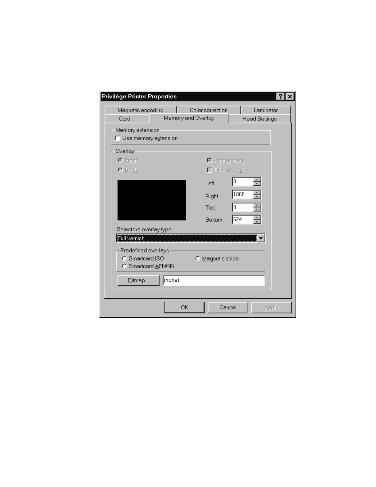
Appendix C
980179-001 Rev. A 87
Page 96

Appendix C
TheHeadSettingstabofferssliders thatcontrol the contrast and intensity related to each
print ribbon panel.
88 980179-001 Rev. A
Page 97

Appendix C
The Magnetic Encoding tab offers settings
that apply when the selected print file contains
encoding data (see Section 3 examples using
Windows driver). This tab then allows users to
specify which non-recording characters in the
document file specify Start of data and End of
data.Notethatdata for eachtrackrequiresthis
format and a track number must follow the
Start characters.
980179-001 Rev. A 89
Page 98

Appendix C
The Color Correction tab has sliders that allowscoloradjustmentsfor red,green,andblue
both intensity and contrast. These settings can
serve to make card images match corresponding monitor images.
90 980179-001 Rev. A
Page 99

Appendix C
The Laminator tab has settings related to the
Lamination Station in P500 card printers. This
tab allows enabling or disabling of lamination,
specification of the Lamination Station ribbon
type,thecardspeedthrough thelaminatorand
the lamination temperature.
980179-001 Rev. A 91
Page 100

Appendix C
Using The
Windows 3.1
Driver
The Privilege Windows 3.1 printer driver
allows control of several printer features when
printing from non-WindCard™ Windows™
software applications. These features are accessed through the “Printers” control panel in
the Program Manager “Main” group.
92
ForaPrivilege printer,selectPRIVXXX , where
XXX designates the desired installed driver.
Double “click” on the PRIVXXX or select
“Connect” to set the printer to the correct
printer port.
980179-001 Rev. A
 Loading...