

Eltron P310 Maintenance Manual

P310
Maintenance Manual
CP PARD RINTER RODUCTS
©2001 Zebra Technologies Corporation
Manual No. 980264-001 Rev. B

FOREWORD
This manual contains service and repair information for P310 Card Printers manufactured
by Zebra Technology Corporation, Camarillo, California. The contents include maintenance,
diagnosis and repair information.
TECHNICAL SUPPORT
For technical support, users should first contact the distributor that originally sold the
product—phone +1 (800) 344 4003 to locate the nearest Eltron Products Distributor. Eltron
Products offers the following:
U.S.A Europe Asia Latin America
Internet
e-mail
Compu
Serve
Phone
FAX
cardsup@eltron.com eurocardsup@eltron.com asiacardsup@eltron.com latincardsup@eltron.com
+805 578 1800 +33 (0) 2 40 09 70 70 +65 73 33 123 +1 847 584 2714
+1 805 579 1808
+44 (0) 1189 895 762
+33 (0) 2 40 09 70 70
http://www.eltron.com
ftp://ftp.eltron.com
102251,1164
+65 73 38 206 +1 847 584 2725
RETURN MATERIALS AUTHORIZATION
Before returning any equipment to Eltron for either in- or out-of-warranty repairs, contact
the Eltron Repair Administration for a Return Materials Authorization (RMA) number. Then
repackage the equipment, if possible using original packing materials, and mark the RMA
number clearly on the outside. Ship the equipment, freight prepaid, to one of the following
addresses:
For USA and Latin America: For Europe, Asia, and Pacific:
Zebra Technologies Corporation Zebra Technologies Corporation
Eltron Card Printer Products Eltron Card Printer Products
1001 Flynn Road Zone Industrielle Rue d’Amsterdam
Camarillo, CA 93012-8706, USA 44370 Varades, France
Phone: +1 (805) 579-1800 Phone: +33 (0) 2 40 09 70 70
FAX: +1 (805) 579-1808 FAX: +33 (0) 2 40 83 47 45
COPYRIGHT NOTICE
This document contains information proprietary to Zebra Technology Corporation. This
document and the information contained within is copyright by Zebra Technology
Corporation and may not be duplicated in full or in part by any person without prior written
approval of Zebra.
While every effort has been made to keep the information contained within current and
accurate as of the date of publication, no guarantee is given or implied that the document is
error-free or that it is accurate with regard to any specification.
iii

This information is not intended as a license to practice or infringe on the patents of this
company or others. Zebra Technology Corporation reserves the right to modify, update or
revise this information at any time without notice.
TRADEMARKS
Eltron is a trademark of Zebra Technology Corporation. All other marks are trademarks or
registered trademarks of their respective holders.
FCC NOTICE:
This equipment has been tested and found to comply with the limits of a Class A digital
device, pursuant to Part 15 of the FCC Rules. These limits are designed to provide
reasonable protection against harmful interference when the equipment is operated in a
commercial environment. This equipment generates, uses and can radiate radio frequency
energy and, if not installed and used in accordance with the instructions, may cause harmful
interference to radio communications. However, there is no guarantee that interference will
not occur in a particular installation. Operation of this equipment in a residential area is
likely to cause harmful interference in which case the user will be required to correct the
interference at his own expense.
CSA NOTICE:
This equipment does not exceed Class A limits per radio noise emissions for digital
apparatus set out in the Radio Interference Regulation of the Canadian Department of
Communications. Operation in a residential area may cause unacceptable interference to
radio and TV reception requiring the owner or operator to take whatever steps are necessary
to correct the interference.
Ce matériel ne dépasse pas les limites de Classe A d’émission de bruits radioélectriques pour
les appareils numériques telles qu’établies par le ministère des Communications du Canada.
L’utilisation faite en milieu résidentiel peut entraîner le brouillage des réceptions radio et
télé, ce qui obligerait le propriétaire ou l’opérateur à prendre les dispositions nécessaires
pour en éliminer les causes.
iv

Table of Contents
CHAPTER 1 GENERAL DESCRIPTION
PRINTER DESCRIPTION . . . . . . . . . . . . . . . . . . . . . . . . . . 1-1
Options · · · · · · · · · · · · · · · · · · · · · · · · · · · · · · · · · · · · · 1-2
Major Elements . . . . . . . . . . . . . . . . . . . . . . . . . . . . . . . 1-2
Card Feeder · · · · · · · · · · · · · · · · · · · · · · · · · · · · · · · · · · 1-2
Cleaning Roller · · · · · · · · · · · · · · · · · · · · · · · · · · · · · · · · · 1-3
Printer · · · · · · · · · · · · · · · · · · · · · · · · · · · · · · · · · · · · · 1-3
Smart Card Docking(Option) · · · · · · · · · · · · · · · · · · · · · · · · · · 1-3
Magnetic Stripe Encoder(Option) · · · · · · · · · · · · · · · · · · · · · · · · 1-4
ABOUT THIS MANUAL. . . . . . . . . . . . . . . . . . . . . . . . . . . 1-4
CAUTIONARY NOTES . . . . . . . . . . . . . . . . . . . . . . . . . . . 1-5
PACKAGING CONSIDERATIONS. . . . . . . . . . . . . . . . . . . . . . 1-6
PREPARING A STATIC-SAFE WORK AREA . . . . . . . . . . . . . . . . . 1-6
ENVIRONMENTAL AND SHOCK PROTECTION . . . . . . . . . . . . . . 1-6
CHAPTER 2 INSTALLATION AND OPERATION
INSTALLATION . . . . . . . . . . . . . . . . . . . . . . . . . . . . . . . 2-2
Unpacking · · · · · · · · · · · · · · · · · · · · · · · · · · · · · · · · · · · 2-2
Tape and PackingRemovals · · · · · · · · · · · · · · · · · · · · · · · · · · 2-3
Card Input HopperInstallation · · · · · · · · · · · · · · · · · · · · · · · · · 2-3
Card Catcher Installation · · · · · · · · · · · · · · · · · · · · · · · · · · · · 2-4
Cleaning Roller CartridgePreparation · · · · · · · · · · · · · · · · · · · · · · 2-4
Cleaning Roller TapeRemoval · · · · · · · · · · · · · · · · · · · · · · · · · 2-5
Cleaning Roller CartridgeInstallation · · · · · · · · · · · · · · · · · · · · · · 2-5
Location Concerns · · · · · · · · · · · · · · · · · · · · · · · · · · · · · · · 2-6
Attaching Cables · · · · · · · · · · · · · · · · · · · · · · · · · · · · · · · · 2-6
Parallel an SerialCableDiagrams · · · · · · · · · · · · · · · · · · · · · · · · 2-8
OPERATION . . . . . . . . . . . . . . . . . . . . . . . . . . . . . . . . 2-9
Controls and Indicators · · · · · · · · · · · · · · · · · · · · · · · · · · · · · 2-9
Front Panel LEDSignals· · · · · · · · · · · · · · · · · · · · · · · · · · · · · 2-9
Print Head ReleaseandLatch Levers· · · · · · · · · · · · · · · · · · · · · · 2-10
Ribbon Loading · · · · · · · · · · · · · · · · · · · · · · · · · · · · · · · · 2-11
Card Gate Adjustment · · · · · · · · · · · · · · · · · · · · · · · · · · · · · 2-12
Loading Card InputHopper · · · · · · · · · · · · · · · · · · · · · · · · · · 2-13
Starting the CleaningCycle · · · · · · · · · · · · · · · · · · · · · · · · · · 2-14
CHAPTER 3 THEORY OF OPERATION
COLOR FUNDAMENTALS . . . . . . . . . . . . . . . . . . . . . . . . . 3-1
PRINTING . . . . . . . . . . . . . . . . . . . . . . . . . . . . . . . . . 3-7
CARD PATH ELEMENTS . . . . . . . . . . . . . . . . . . . . . . . . . . 3-8
CIRCUIT DESCRIPTIONS . . . . . . . . . . . . . . . . . . . . . . . . . 3-10
Print Head Circuitry · · · · · · · · · · · · · · · · · · · · · · · · · · · · · · 3-12
v

Motor Control Circuitry · · · · · · · · · · · · · · · · · · · · · · · · · · · · 3-14
Status Circuitry · · · · · · · · · · · · · · · · · · · · · · · · · · · · · · · · 3-16
Serial and ParallelPortCircuitry · · · · · · · · · · · · · · · · · · · · · · · · 3-18
USB Port Circuitry(Optional) · · · · · · · · · · · · · · · · · · · · · · · · · 3-20
Magnetic Stripe EncoderCircuitry(Option)· · · · · · · · · · · · · · · · · · · 3-21
Smart Card Circuitry(Option) · · · · · · · · · · · · · · · · · · · · · · · · · 3-22
Operator Panel Circuitry · · · · · · · · · · · · · · · · · · · · · · · · · · · · 3-24
Power Regulator Circuitry · · · · · · · · · · · · · · · · · · · · · · · · · · · 3-24
CHAPTER 4 TROUBLESHOOTING
DIAGNOSING BASIC PRINTER PROBLEMS . . . . . . . . . . . . . . . . 4-2
DIAGNOSING COMPUTER INTERFACE PROBLEMS . . . . . . . . . . . . 4-4
CHAPTER 5 REPLACEMENT PROCEDURES
REQUIRED TOOLS . . . . . . . . . . . . . . . . . . . . . . . . . . . . . 5-2
PART REPLACEMENTS . . . . . . . . . . . . . . . . . . . . . . . . . . . 5-3
Rear Case Removal · · · · · · · · · · · · · · · · · · · · · · · · · · · · · · · 5-3
Front Case Removal · · · · · · · · · · · · · · · · · · · · · · · · · · · · · · 5-4
Bottom Plate Removal · · · · · · · · · · · · · · · · · · · · · · · · · · · · · 5-5
Power Supply Replacement · · · · · · · · · · · · · · · · · · · · · · · · · · · 5-6
Card Feeder PartRemovals · · · · · · · · · · · · · · · · · · · · · · · · · · · 5-7
Print Head Replacement · · · · · · · · · · · · · · · · · · · · · · · · · · · · 5-8
Fan Removal · · · · · · · · · · · · · · · · · · · · · · · · · · · · · · · · · 5-13
Ribbon Sensor Removal · · · · · · · · · · · · · · · · · · · · · · · · · · · · 5-14
Front Belt Removals · · · · · · · · · · · · · · · · · · · · · · · · · · · · · · 5-15
CPU and EncoderBoardReplacements · · · · · · · · · · · · · · · · · · · · 5-16
Rear Plate Removal · · · · · · · · · · · · · · · · · · · · · · · · · · · · · · 5-17
Daughter Board Removal · · · · · · · · · · · · · · · · · · · · · · · · · · · 5-18
Flag and HeadLatchSensor BoardReplacement. · · · · · · · · · · · · · · · 5-19
Rear Belt andO-RingRemoval · · · · · · · · · · · · · · · · · · · · · · · · · 5-20
Smart Card InterfaceBoardReplacement (Option) · · · · · · · · · · · · · · · 5-21
Encoder Head Replacement · · · · · · · · · · · · · · · · · · · · · · · · · · 5-24
Head Up-Down, Stepper,andRibbon TakeUp Motors · · · · · · · · · · · · · 5-28
Ribbon Supply SpindleandClutch Replacements · · · · · · · · · · · · · · · 5-30
Ribbon Take UpSpindleReplacements · · · · · · · · · · · · · · · · · · · · 5-32
CHAPTER 6 MAINTENANCE AND ADJUSTMENTS
CLEANING MATERIALS. . . . . . . . . . . . . . . . . . . . . . . . . . . 6-2
CLEANING . . . . . . . . . . . . . . . . . . . . . . . . . . . . . . . . . 6-2
Card Transport, Platen,andCleaning Rollers · · · · · · · · · · · · · · · · · · 6-2
Cleaning the PrintHead· · · · · · · · · · · · · · · · · · · · · · · · · · · · · 6-4
OBTAINING AND INSTALLING FIRMWARE UPDATES . . . . . . . . . . . 6-5
ADJUSTMENTS . . . . . . . . . . . . . . . . . . . . . . . . . . . . . . . 6-5
Stepper Belt Tension · · · · · · · · · · · · · · · · · · · · · · · · · · · · · · 6-6
vi

Print Head TiltAdjustments · · · · · · · · · · · · · · · · · · · · · · · · · · · 6-9
Print Head PeelBarPosition Adjustment · · · · · · · · · · · · · · · · · · · · 6-12
Image Centering· · · · · · · · · · · · · · · · · · · · · · · · · · · · · · · · 6-13
APPENDIX A TEST SOFTWARE
INSTALLATION. . . . . . . . . . . . . . . . . . . . . . . . . . . . . . . A-1
OPERATION . . . . . . . . . . . . . . . . . . . . . . . . . . . . . . . . A-1
Launching the CardPrinterTest Software · · · · · · · · · · · · · · · · · · · · A-2
Changing the COMPort · · · · · · · · · · · · · · · · · · · · · · · · · · · · A-4
Operating in TerminalMode · · · · · · · · · · · · · · · · · · · · · · · · · · A-5
Typical Sub List· · · · · · · · · · · · · · · · · · · · · · · · · · · · · · · · · A-6
Sensor Test Selection · · · · · · · · · · · · · · · · · · · · · · · · · · · · · · A-7
Table of Figures
Figure 1-1. Major Elements . . . . . . . . . . . . . . . . . . . . . . . . . 1-2
Figure 2-1. Packaging Materials . . . . . . . . . . . . . . . . . . . . . . . 2-2
Figure 2-2. Tape and Packing.. . . . . . . . . . . . . . . . . . . . . . . . 2-3
Figure 2-3. Card Input Cartridge Installation. . . . . . . . . . . . . . . . . 2-3
Figure 2-4. Card Output Hopper. . . . . . . . . . . . . . . . . . . . . . . 2-4
Figure 2-5. Cleaning Roller Installation. . . . . . . . . . . . . . . . . . . . 2-4
Figure 2-6. Cleaning Roller Cartridge Preparation.. . . . . . . . . . . . . . 2-5
Figure 2-7. Cleaning Roller Cartridge Installation. . . . . . . . . . . . . . . 2-5
Figure 2-8. Cables. . . . . . . . . . . . . . . . . . . . . . . . . . . . . . 2-6
Figure 2-9. USB Issues. . . . . . . . . . . . . . . . . . . . . . . . . . . . 2-7
Figure 2-10. Cable Wiring. . . . . . . . . . . . . . . . . . . . . . . . . . 2-8
Figure 2-11. Controls and Indicators . . . . . . . . . . . . . . . . . . . . 2-9
Figure 2-12. Print and Lamination Head Latch and Release Levers. . . . . 2-10
Figure 2-13. Ribbon Installation. . . . . . . . . . . . . . . . . . . . . . . 2-11
Figure 2-14. Card Gate Adjustment . . . . . . . . . . . . . . . . . . . . 2-12
Figure 2-15. Card Cartridge Loading. . . . . . . . . . . . . . . . . . . . 2-13
Figure 2-16. Cleaning Card Installation. . . . . . . . . . . . . . . . . . . 2-14
Figure 3-1. Card Path Elements.. . . . . . . . . . . . . . . . . . . . . . . 3-9
Figure 3-2. Printer Module Block Diagram. . . . . . . . . . . . . . . . . 3-11
Figure 3-3. Print Head Circuitry. . . . . . . . . . . . . . . . . . . . . . . 3-13
Figure 3-4. Motor Control Circuitry. . . . . . . . . . . . . . . . . . . . . 3-15
Figure 3-5. Status Circuitry. . . . . . . . . . . . . . . . . . . . . . . . . 3-17
Figure 3-6. Serial and Parallel Port Circuitry. . . . . . . . . . . . . . . . . 3-19
Figure 3-7. USB Port Circuitry.. . . . . . . . . . . . . . . . . . . . . . . 3-20
Figure 3-8. Magnetic Stripe Encoder Elements.. . . . . . . . . . . . . . . 3-21
Figure 3-9. Smart Card Circuitry.. . . . . . . . . . . . . . . . . . . . . . 3-23
Figure 3-10. Operator Panel Circuitry . . . . . . . . . . . . . . . . . . . 3-24
Figure3-11. Power Regulator Circuitry. . . . . . . . . . . . . . . . . . . 3-24
vii

Figure 4-1. Problems Duplicated by a Test Print. . . . . . . . . . . . . . . 4-2
Figure 4-2. Interface Diagnostic Flow.. . . . . . . . . . . . . . . . . . . . 4-4
Figure 5-1. Rear Case Fasteners. . . . . . . . . . . . . . . . . . . . . . . 5-3
Figure 5-2. Front Case Removal. . . . . . . . . . . . . . . . . . . . . . . 5-4
Figure 5-3. Bottom Plate Removal. . . . . . . . . . . . . . . . . . . . . . 5-5
Figure 5-4. Bottom Plate and Power Supply. . . . . . . . . . . . . . . . . 5-6
Figure 5-5. Card Feeder Rear . . . . . . . . . . . . . . . . . . . . . . . . 5-7
Figure 5-6. Print Head Upper Fasteners . . . . . . . . . . . . . . . . . . . 5-8
Figure 5-7. Print Head Ground Lug . . . . . . . . . . . . . . . . . . . . . 5-9
Figure 5-8. Print Head Assembly Removal . . . . . . . . . . . . . . . . . 5-10
Figure 5-9. Print Head Connectors. . . . . . . . . . . . . . . . . . . . . 5-11
Figure 5-10. Properly Positioned Print Head . . . . . . . . . . . . . . . . 5-12
Figure 5-11. Fan Replacement . . . . . . . . . . . . . . . . . . . . . . . 5-13
Figure 5-12. Ribbon Sensor Removal. . . . . . . . . . . . . . . . . . . . 5-14
Figure 5-13. Front Belts. . . . . . . . . . . . . . . . . . . . . . . . . . . 5-15
Figure 5-14. CPU and Encoder Boards. . . . . . . . . . . . . . . . . . . 5-16
Figure 5-15. Rear Plate Removals. . . . . . . . . . . . . . . . . . . . . . 5-17
Figure 5-16. Daughter Board. . . . . . . . . . . . . . . . . . . . . . . . 5-18
Figure 5-17. Flag and Head Latch Sensor Board.. . . . . . . . . . . . . . 5-19
Figure 5-18. Rear Belts and O-Ring. . . . . . . . . . . . . . . . . . . . . 5-20
Figure 5-19. Smart Card PWB . . . . . . . . . . . . . . . . . . . . . . . 5-21
Figure 5-20. Smart Card Solenoid Removal . . . . . . . . . . . . . . . . 5-22
Figure 5-21. Smart Card Docking Station . . . . . . . . . . . . . . . . . 5-23
Figure 5-22. Encoder Station Shroud. . . . . . . . . . . . . . . . . . . . 5-24
Figure 5-23. Encoder Head (Above-the-Card-Path). . . . . . . . . . . . . 5-24
Figure 5-24. Encoder Station Pressure Roller Rod. . . . . . . . . . . . . . 5-25
Figure 5-25. Encoder Head Pinch Roller Removal.. . . . . . . . . . . . . 5-26
Figure 5-26. Pressure Roller Rod Removal.. . . . . . . . . . . . . . . . . 5-27
Figure 5-27. Encoder Head Fasteners. . . . . . . . . . . . . . . . . . . . 5-27
Figure 5-28. Encoder Head Protective Tape.. . . . . . . . . . . . . . . . 5-28
Figure 5-29. Middle Panel Parts . . . . . . . . . . . . . . . . . . . . . . 5-29
Figure 5-30. Supply Spindle Assembly . . . . . . . . . . . . . . . . . . . 5-31
Figure 5-31. Ribbon Take Up Spindle . . . . . . . . . . . . . . . . . . . 5-33
Figure 6-1. Cleaning Swabs . . . . . . . . . . . . . . . . . . . . . . . . . 6-2
Figure 6-2. Card Transport Rollers. . . . . . . . . . . . . . . . . . . . . . 6-3
Figure 6-3. Print Head Cleaning. . . . . . . . . . . . . . . . . . . . . . . 6-4
Figure 6-4. Stepper Motor Fasteners. . . . . . . . . . . . . . . . . . . . . 6-6
Figure 6-5. Stepper Motor Belt Tensioning Fixture (Part No. 900116-001). . 6-7
Figure 6-6. Stepper Belt Tensioning. . . . . . . . . . . . . . . . . . . . . 6-8
Figure 6-7. Head Alignment Test Cards.. . . . . . . . . . . . . . . . . . . 6-9
Figure 6-8. Image Brightness Adjustment. . . . . . . . . . . . . . . . . . 6-10
Figure 6-9. Lower Print Head Fasteners. . . . . . . . . . . . . . . . . . . 6-11
Figure 6-10. Peel Bar Fasteners. . . . . . . . . . . . . . . . . . . . . . . 6-12
viii
CHAPTER 1
GENERAL DESCRIPTION
1.1 PRINTER DESCRIPTION
Eltron® Model P310 printers offer low cost solutions to those that need to print, encode
magnetic stripes, or program smart plastic cards. Eltron offers imaging ribbon varieties
that include dye sublimation color, dye sublimation black, thermal transfer monochrome
in various colors, and scratch-off gray. Dye sublimation ribbons include panels that
support the application of a clear protective varnish.
Standard P310 printers have a Card Feeder and Printer Station, supporting single-side
plastic card printing. Users can set the Card Feeder for the wide range of plastic card
thicknesses offered.
Software support exists for the selection, imaging, and positioning of two internal fonts
and eight bar code formats. This means that the units recognize associated software
commands. Users canavoidusingeither anapplication or the printer driver to imagethese
980264-001 Rev. B 1-1
CHAPTER 1
objects. For those who wish to create card graphics from their software applications, the
units ship withbothWindows 95/98and NT drivers. Both drivers support TrueTypefonts.
1.1.1 Options
Plastic card varieties include Smart Cards and cards with Magnetic Stripes. Because not
everyone may want to use associated capabilities, integration of related hardware is
offered as options. Encoders can place data on either high- or low-coercivity stripes. With
reference to the Card Loading, P310 Printers can be configured for either up- or
down-facing magnetic stripes. However, unless specified otherwise, P310 Printers ship
with the read/write heads positioned to encode down-facing stripes—printing always
occurs on the up-facing card surface.
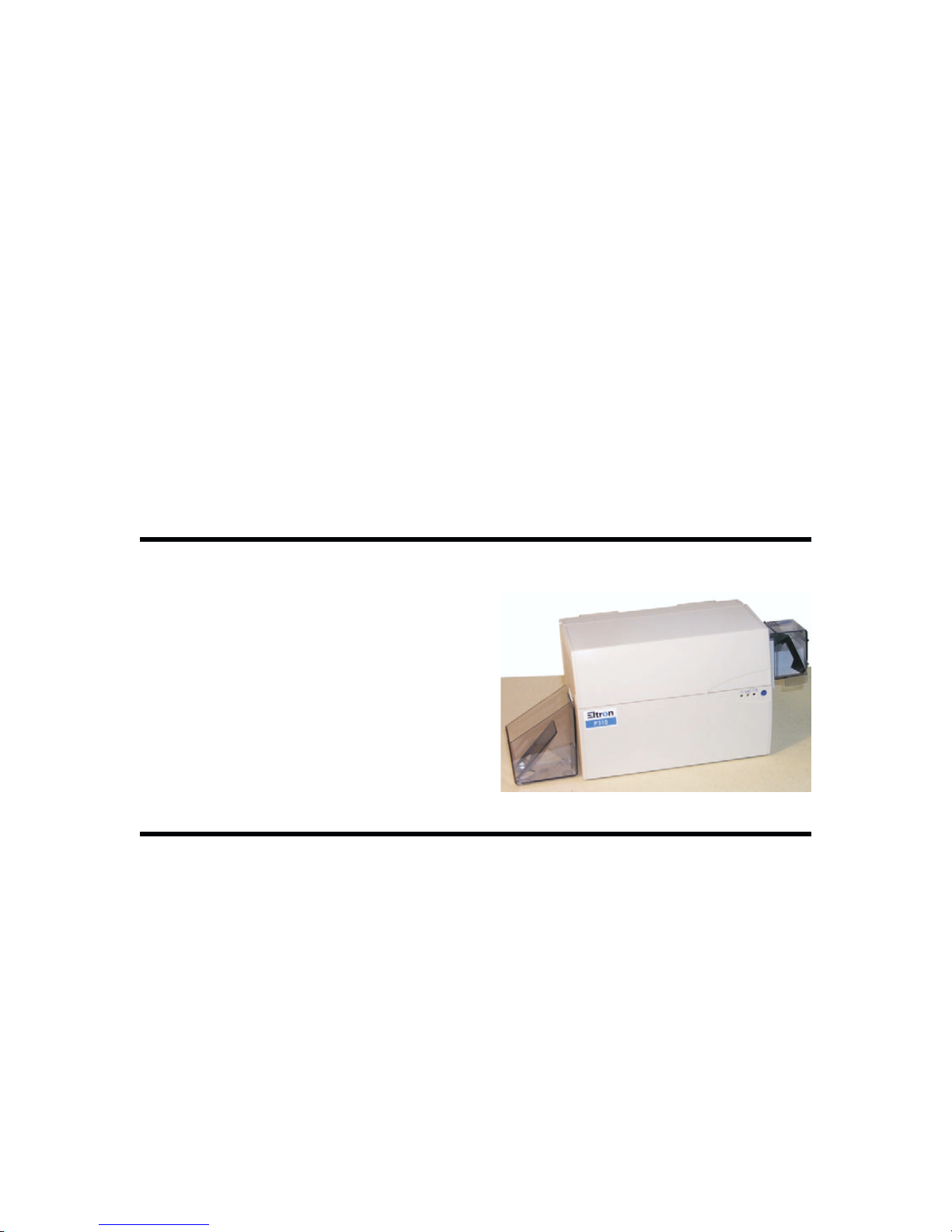
1.2 Major Elements
Figure 1-1 shows the Printer assemblies visible with the cover raised.
Figure 1-1. Major Elements
1.2.1 Card Feeder
With the Card Feeder set for a proper thickness, Cards placed in the Card Input Hopper
enter the printer oneat a time in response toCard Feed Commands. A manualCard Gate
adjustment lets users establish a suitable card thickness setting. Eltron Card Printer
Products offers cards in popular 0.02- and 0.03-inch thicknesses. However, users can
1-2 980264-001 Rev.B

CHAPTER 1
adjust the feeder for other thicknesses as well. The Card Feed Hopper, has an attached
Card Weight that positions itself on top of a stack of cards in the Hopper. This added
weight increases the grip of the card feed rollers and assures reliable card feeds throughout
cartridge-full to cartridge-empty conditions.
1.2.2 Cleaning Roller
Cards transitioning between the Card Input Hopper and the Printer (or Smart Card
Station) travel through a pair of rollers. Above one of these rollers resides a removable
cartridge that contains the CleaningRoller. A tacky surface on this rollercollects any lint or
other loose particles that may adhere to the underlying rollers due to contact with passing
cards. To maintain its ability to collect particles, users must periodically replace the
Cleaning Roller. Users should watch for evidence of particle buildup on the Cleaning
Roller or print anomalies having related characteristics.
1.2.3 Printer
Card imaging occurs as the cards transition through the Printer Station.For colorimaging,
the cards transition past the Print Head three times. Yellow, magenta, and cyan (YMC)
dyes transfer from ribbon panels onto the cards in amounts controlled by heat produced
by Print Head elements. Each of the 32K color possibilitiesresults from a particular mix of
the YMC dyes. The density of Print Head elements produces images with 300
dot-per-inch (dpi) resolution. One of the commonly used color ribbons also has panels
that can lay down black monochrome images and a protective clear coating, each in a
related additional pass across the Print Head.
Whereas the colorpanels of color ribbons laydown dye sublimation dyes, theblack panel
of these same ribbons deposits a thermal transfer resin (Kr) that only images at one heat
setting. While this essentially eliminates resin as a medium for gray scale, a capability
already made available by the YMC panels, resin serves as a particularly good choice for
text and bar codes. By ending the imaging sequence with a clear overlay coating (O),
cards receive added durability and a resistance to fading of the CMY dyes. In summary,
images produced using color ribbons typically have five panels (CMYKrO) and require a
corresponding five passes across the Print Head.
Ribbons also exist insingle-coated and two-panel varieties. Single-coated ribbons deposit
a resin. Users have a choice of many resin colors. Two-panel ribbon varieties have either
black dye (Ks) or Kr panels alternated with panels that lay down clear overlay coatings.
Being a dye, the Ks material supports gray-scale imaging, which offers users an ideal
means of producing black-and-white photo quality images.
While the forgoing describesthe major imaging ribbon types, readersshould check the list
of supplies for other varieties that can serve special imaging needs.
1.2.4 Smart Card Docking (Option)
At a Smart Card Station, Smart Card contacts connect to a DB-9 connector at the rear of
the Printer. This implementation supports the use of an external Smart Card
Programming device. Docking occurs with a card positioned under the contacts; after
which, a solenoid mechanism raises the card to make the connections.
980264-001 Rev. B 1-3

CHAPTER 1
1.2.5 Magnetic Stripe Encoder (Option)
Printers equipped with Magnetic Stripe Encoders fully support the encoding of cards with
magnetic stripes. This includes several encoding formats. Read-After-Write checking
occurs with each encoding to assure a reliable result. After receipt of related data,
encoding of all three tracks occurs in a single pass through the encoder. Encoding occurs
as the cards transition between the Print Station and the Card Catcher, where the
read/write heads and an associated card sensor reside.
1.3 ABOUT THIS MANUAL
Eltron Products has directed the Information contained in this manual at returning P310
printer functions to normal operation in the shortest time possible. With this in mind,
service personal should focus on items listed in their recommended spares list. Avoid
lower level replacements whenever possible. Service personnel should keep a log of the
repairs made in support of the concept of continuous product improvement. Chapters
include: General Description, Installation and Operation, Theory of Operation,
Troubleshooting, Part Replacement Procedures, and Maintenance and Adjustments.
Follow the instructions as closely as possible. When unsure of any procedure, please
contact either an Eltron Service Representative (contact Eltron Product Management for
nearest representative) orEltronTechnical Supportat 1-800-344-4003 or 805-578-1800.
Eltron Products stocks all commonly used replacement parts for P310 Printers. For depot
repairs, contact Eltron Sales to place orders and to establish a program for bulk purchases
and credited returns of warranted parts.
1-4 980264-001 Rev.B

1.4 CAUTIONARY NOTES
Exercise reasonable care when servicing P310 printers, as follows:
Other than prescribed operator maintenance, only qualified
personnel should remove the case or otherwise attempt to
repair this equipment. Eltron offers product training to those
wishing to service this equipment.
Servicing personnel must avoid touching exposed circuitry.
Inputs to the Power Supply operate at power line voltages. Any
removal of protective insulation can expose dangerous voltages.
Always remove the power cord while effecting repairs.
During operation, the Print Head operates at an elevated
temperature. Exercise caution when touching parts on or near
this area.
CHAPTER 1
Servicing Personnel should avoid any rough handling of the
Printers or their component parts. The icon to the left also
serves as an indicator alerting conditions of general concern to
users.
An electrostatic discharge (ESD) of energy can damage or
destroy the circuit components inside the Printer. People
acquire such charges while they move around. ESD problems
typically increase during periods of low humidity.
Users should not twist the Printer Ribbon Take Up Spindle
manually. Doing so unnecessarily stresses an associated belt.
Any slack left after a ribbon installation gets removed during an
initialization that occurs with the latch-down of the Print Head.
Particle contamination, such as dust, can reduce image quality
and produce excess wear to some printer components. Locate
Printers and print media in areas essentially contamination free.
To avoid fiber deposits, any Cleaning Swabs used must have
foam tips. Also, cleaning solution impurities can leave deposits.
Therefore, only use 99-percent pure or better alcohol.
980264-001 Rev. B 1-5

CHAPTER 1
1.5 PACKAGING CONSIDERATIONS
The factory-supplied shipping carton contains the Printer placed inside a protective ESD
(Electrostatic Discharge) bag and suspended in form-fitting end cushions made from a
foam material. These are the only materials approved for P310 shipments. Any shipping
damage may not be covered by either the product warranty or the carrier if the printer is
shipped with packaging materials that do not meet associated shipping standards. If
necessary, order replacement factory-approved shipping materials from a P310 printer
distributor.
1.6 PREPARING A STATIC-SAFE WORK AREA
To avoid component damage while performing troubleshooting and repair procedures,
service personnel should work in a static-safe area. Items under test should rest on a
properly grounded, conductive, and cushioned mat. Service personnel should wear a
conductive wrist strap. (Most electronic supply stores carry ESD protective devices. For a
local supplier, contact 3M Corporation at 1-800-328-1368 or 512-984-1800.)
1.7 ENVIRONMENTAL AND SHOCK PROTECTION
Avoid extremes of temperature and humidity or mishandling. These conditions can
damage most electronic equipment.
When moving the printer from a cool, dry location to a warmer, more humid location,
allow the printer to temperature stabilize for at least 30 minutes before opening the
protective ESD bag. Otherwise, moisture can condense on the surface of many
components. Moisture can degrade performance or even damage some components.
Avoid rough handling. Careful handling can avoid possible mechanical damage that
might otherwise result from dropping or impacting the printer on a hard surface.
1-6 980264-001 Rev.B

CHAPTER 2
INSTALLATION AND OPERATION
This chapter includes information on the following:
• Unpacking
• Installation
• Controls and Indicators
• Card and Ribbon Loading
Similar descriptions also appear in the associated User’s Guide and other manuals
shipped with the printer. The intent here is to make this manual as complete as possible
with a minimum of references to other manuals. Operations related to software
applications and the Windows Driver do not appear in this manual. Information on the
Test Software appears in Appendix A.
980264-001 Rev. B 2-1
CHAPTER 2
2.1 INSTALLATION
2.1.1 Unpacking
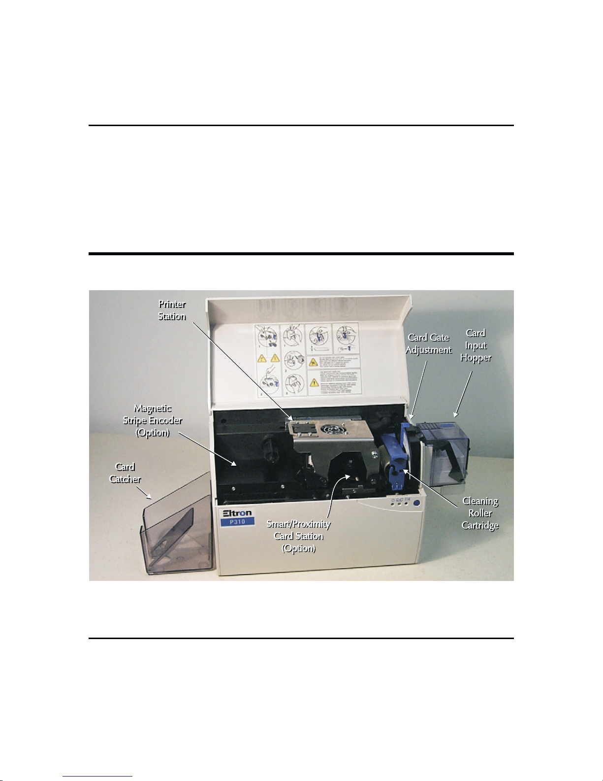
Figure 2-1 shows the carrier-approved packaging materials used for shipping and how
these items fit within inside and outside cartons.
Note that customers should keep these materials on hand for future shipping needs. The
product warranty may not cover a printer damaged during a shipment if the printer is
packaged using unapproved shipping materials. If necessary, users can order
replacements before shipping the Printer.
Figure 2-1. Packaging Materials
2-2 980264-001 Rev.B
CHAPTER 2
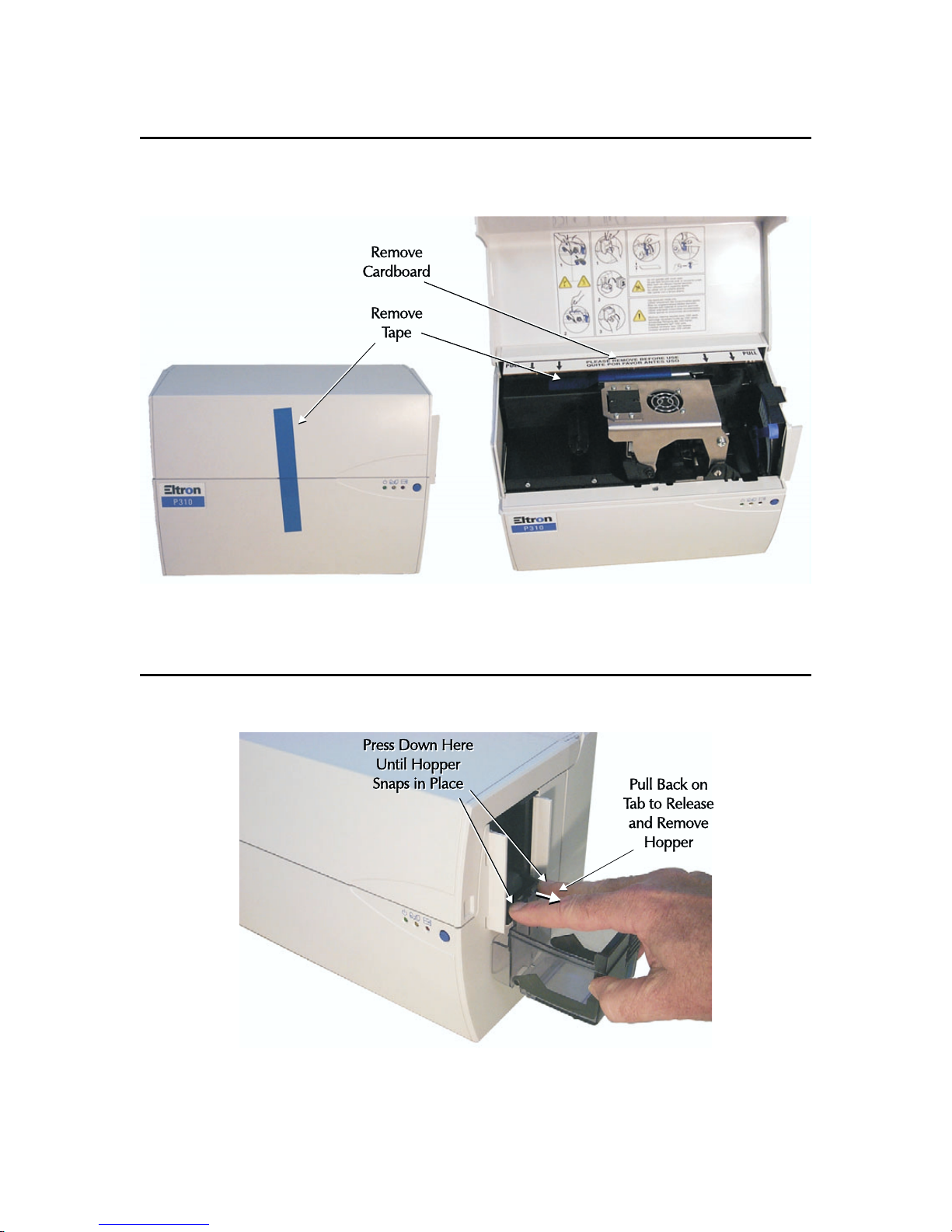
2.1.2 Tape and Packing Removals
Figure 2-2 shows the tape and packing material that requires removal prior to printer
operation.
Figure 2-2. Tape and Packing.
2.1.3 Card Input Hopper Installation
Figure 2-3 shows Installation of the Card Input Cartridge.
Figure 2-3. Card Input Cartridge Installation.
980264-001 Rev. B 2-3

CHAPTER 2
2.1.4 Card Catcher Installation
Figure 2-4 shows the installation of the Card Catcher.
Figure 2-4. Card Output Hopper.
2.1.5 Cleaning Roller Cartridge Preparation
Figure 2-5 shows how to install the Cleaning Roller into the Cleaning Roller Cartridge.
Figure 2-5. Cleaning Roller Installation.
2-4 980264-001 Rev.B
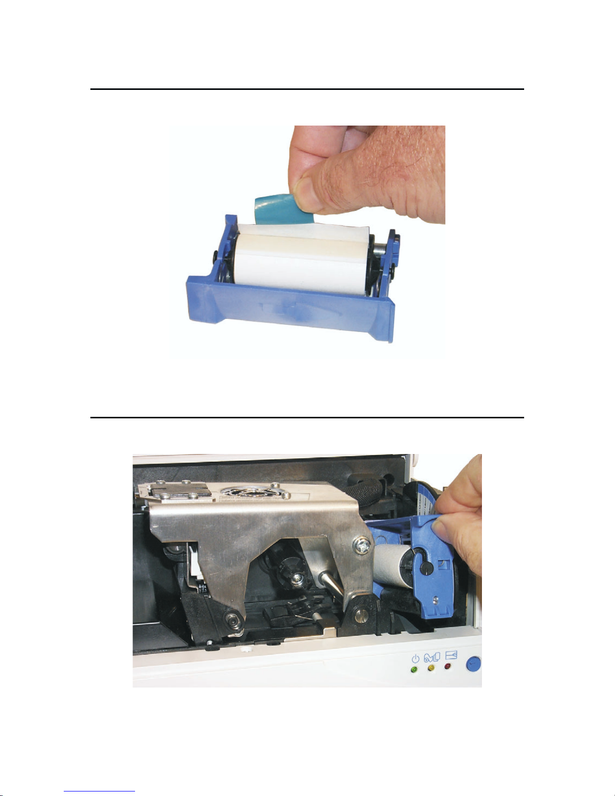
2.1.6 Cleaning Roller Tape Removal
Figure 2-6 shows removal of the tape protecting the tacky surface.
CHAPTER 2
Figure 2-6. Cleaning Roller Cartridge Preparation.
2.1.7 Cleaning Roller Cartridge Installation
Figure 2-7 shows where the Cleaning Roller Cartridge fits into the Printer.
Figure 2-7. Cleaning Roller Cartridge Installation.
980264-001 Rev. B 2-5
CHAPTER 2
2.1.8 Location Concerns
Users should avoid dusty locations. Until ready for use, keep ribbon and card media in their
cartons. Select a location that offers easy access to all sides plus an unrestricted air flow. Avoid
locations that experience extremes in temperature and/or humidity.
2.1.9 Attaching Cables
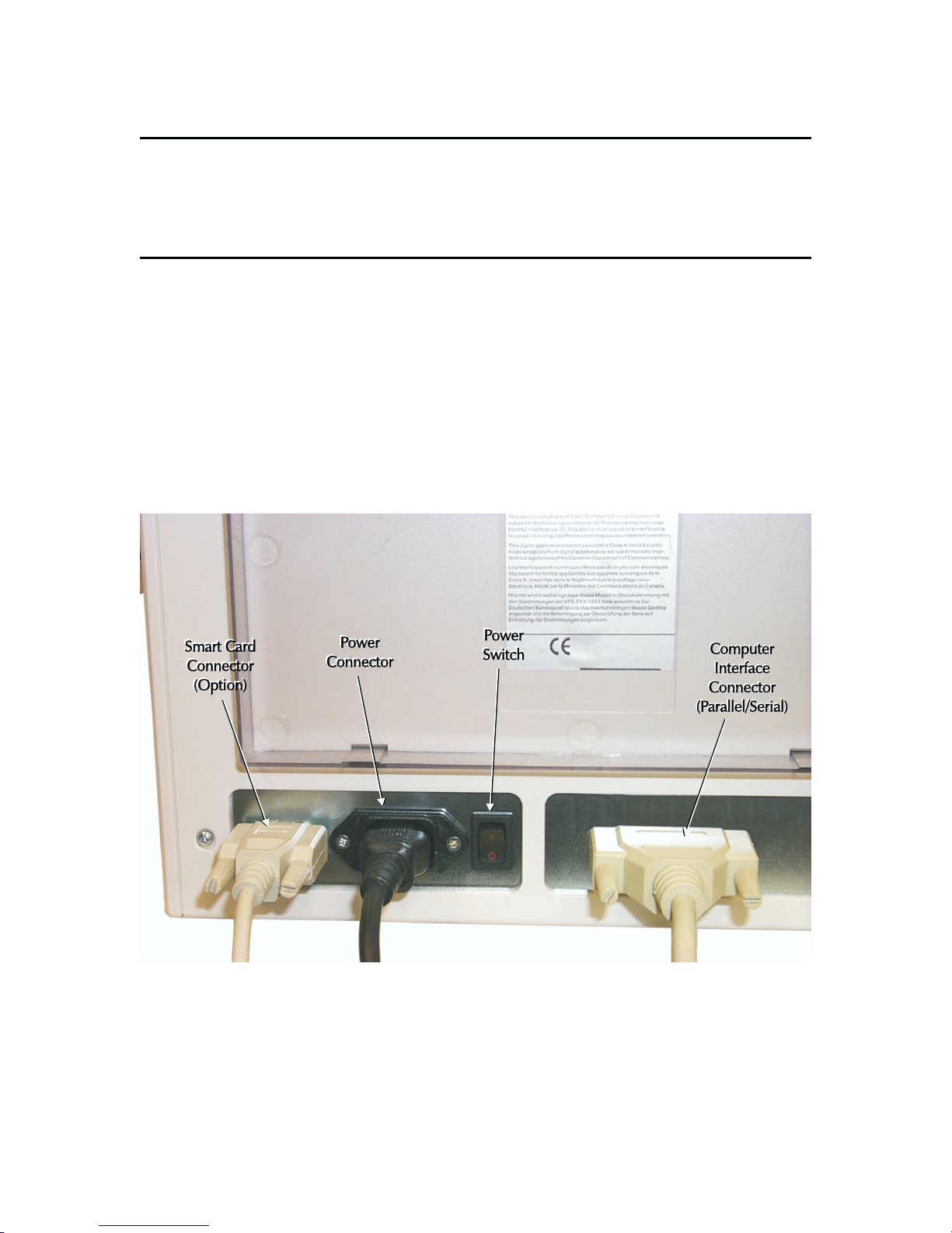
Figure 2-8 shows the Rear Panel of a Printer. This panel has the following:
Power ON-OFF Switch
•
Power Connector
•
Computer Interface Connector s
•
Smart Card Connector (Option)
•
The internal power supply automatically adjusts to most of the ac outlet voltages
encountered world wide. Always connect the Power Cable last.
Figure 2-8. Cables.
2-6 980264-001 Rev.B
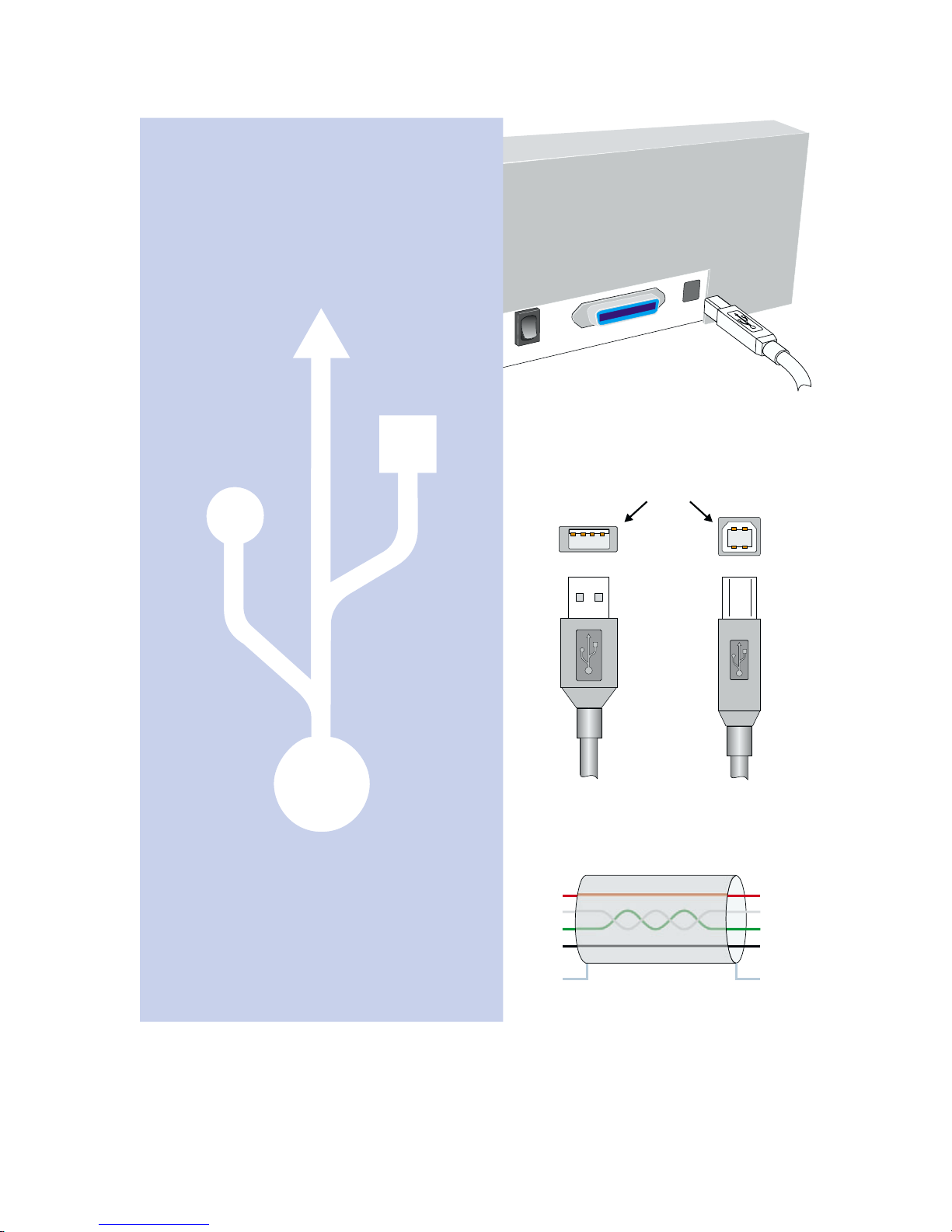
USB Concerns
(USB Specification Rev. 2.0)
1. USB-Equipped Host Computers have Hub
connection(s) and software that supports the
connections for up to 127 devices (either USB
Functions or USB Hubs), all hot swapable.
2. Hubs implement one connection path upstream
to, or toward, the Host and typically several Ports
for downstream Functions and/or other Hub
connections. Functions refer to Printers, Mice,
Keyboards, etc.
CHAPTER 2
3. USB Cables e have both A- and B-type
ach
connectors. The A connectors attach to upstream
devices, while the B connectors attach to
downstream devices. Hub loopback connections
(requiring an A-to-A cable) are not allowed.
4. System Software keeps track of the paths and path
parameters both to and from Functions (as Pipes).
System Software does not support more than five
Hubs, not counting the host, along any path.
5. A Pipe can operate at USB High Speed (480Mb/s),
USB Full Speed (12Mb/s), or USB Low Speed (1.5
Mb/s). Functions report needed parameters as part
of setup phases during operations (e.g., following
hot swaps).
6. USB Ports and Cables have a shield and four
conductors—two for data and two that can supply
5 volts to Bus-Powered Devices.
7. It is important to have cables that can support the
bandwidth requirements of a particular path.
Speed
Cables should not be used in paths that can
Low
also operate at High/Full Speeds.
8. Cable designers must meet specified requirements
for data integrity between devices by using
materials for the lengths offered. Extension
suitable
Cables can add factors that breach critical design
elements and should not be used.
VBus1
D+ 2
D- 3
Ground 4
Shield
A
3
4
2
End Views
1
Cable Wiring
B
2
3
1
4
1VBus
2D+
3D4 Ground
Shield
Figure 2-9. USB Issues.
980264-001 Rev. B 2-7
CHAPTER 2
2.1.10 Parallel an Serial Cable Diagrams
Figure 2-10 shows the cable wiring.
HOST
STROBE
DATA 0
DATA 1
DATA 2
DATA 3
DATA 4
DATA 5
DATA 6
DATA 7
ACK/
BUSY
PAPER ERR.
READY
INIT
ERROR/
N/A
N/A
N/A
SIG. GND
SIG. GND
SIG. GND
SIG. GND
SIG. GND
SIG. GND
SIG. GND
DB-25
Pin No.
1
2
3
4
5
6
7
8
9
10
11
12
13
14
15
16
17
18
19
20
21
22
23
24
25
DB-25
Pin No.
1
2
3
4
5
6
7
8
9
10
11
12
13
14
15
16
17
18
19
20
21
22
23
24
25
PRINTER
MODULE
STROBE
DATA 0
DATA 1
DATA 2
DATA 3
DATA 4
DATA 5
DATA 6
DATA 7
ACK/
BUSY
PAPER ERR.
READY
INIT
ERROR/
N/A
N/A
N/A
SIG. GND
SIG. GND
SIG. GND
SIG. GND
SIG. GND
SIG. GND
SIG. GND
HOST
N/A
RxD
TxD
DTR
GND
DSR
RTS
CTS
RI
Figure 2-10. Cable Wiring.
2-8 980264-001 Rev.B
FemaleDB-25toMaleDB-25
DB-9
Pin No.
1
2
3
4
5
6
7
8
9
DB-9
Pin No.
1
2
3
4
5
6
7
8
9
Female DB-9 to Male DB-9
PRINTER
MODULE
N/A
RxD
TxD
DTR
GND
DSR
RTS
CTS
RI
CHAPTER 2
2.2 OPERATION
2.2.1 Controls and Indicators
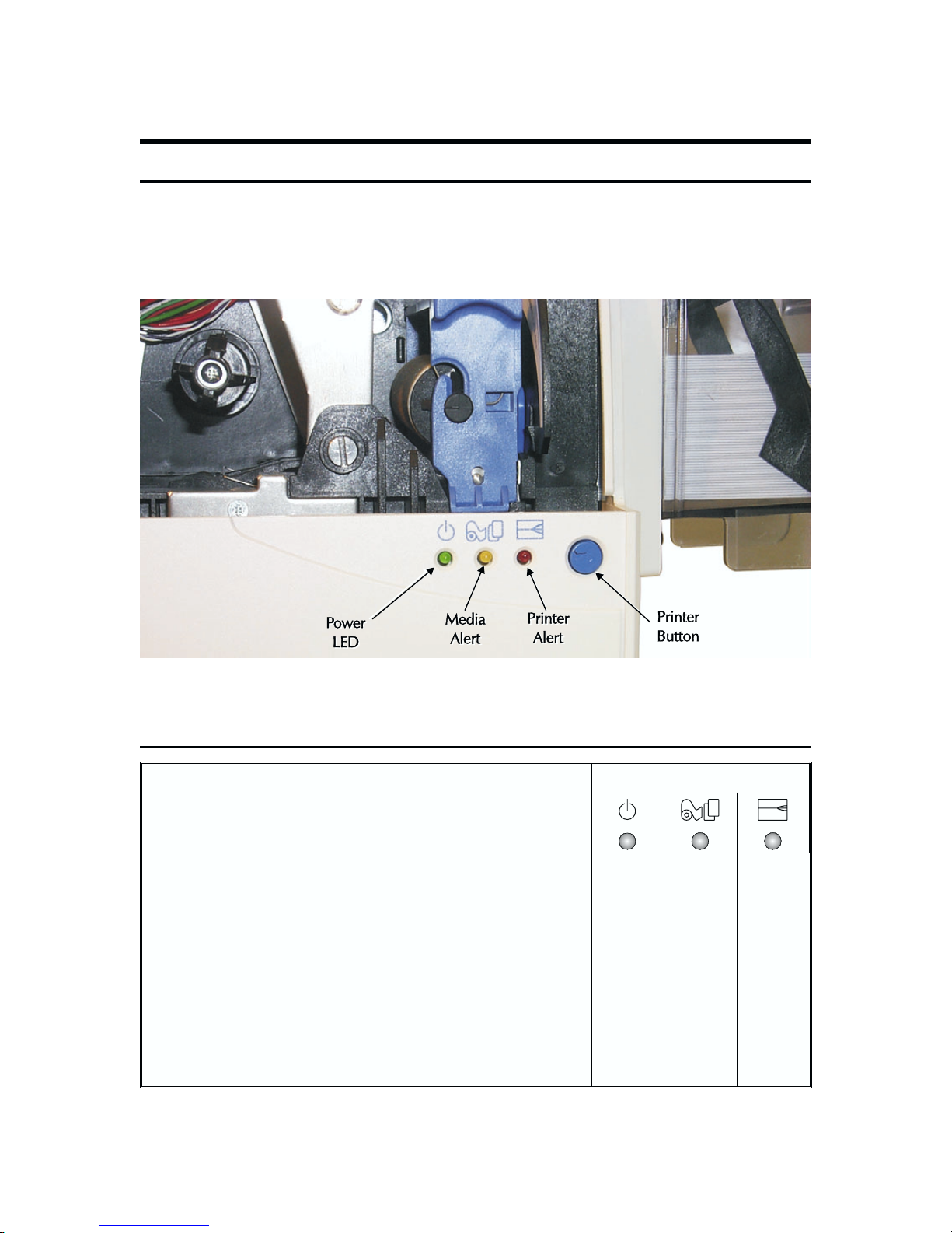
Figure 2-11 shows the push-button switch and LEDs (light emitting diodes) that appear on
the front of the Printer. The Power Switch resides on the rear. Users press the Printer
Button to reinitialize P310 printers. Users also press this button to signal when a user
intervention has corrected an Alert condition that has suspended operations.
Figure 2-11. Controls and Indicators
2.2.2 Front Panel LED Signals
LED Signals
Conditions
Power Off (Check Cord, Power Switch, etc.) Off Off Off
Processing Alert (Preparing to Print) Flashing Off Off
Card Alert (Check Card Feed Hopper) On On Off
Ribbon Alert (Check Ribbon) On Flashing Off
Printer Alert (CheckHeadDown, CardJam, Command Error) On Off On
Encoder Alert (Check Card Stripe Side, Command Error) On Off Flashing
Cleaning Alert (Time to Run Cleaning Card Sequence) On Flashing Flashing
Print Head Alert (Too Hot, Wait for Automatic Recovery) Flashing Flashing Flashing
980264-001 Rev. B 2-9
CHAPTER 2
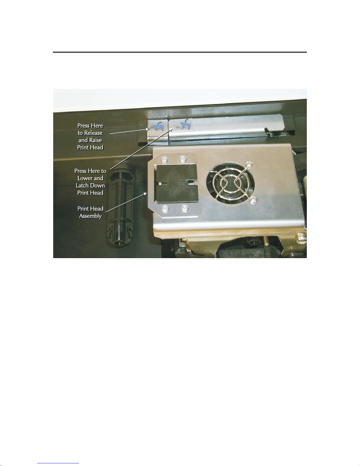
2.2.3 Print Head Release and Latch Levers
Figure 2-12 shows the Release and Latch levers for the Print Head. Users open the Cover
and raise the Print Head during manual Cleaning Procedures, removal of card jams, and
ribbon loads.
Figure 2-12. Print and Lamination Head Latch and Release Levers.
2-10 980264-001 Rev.B
CHAPTER 2
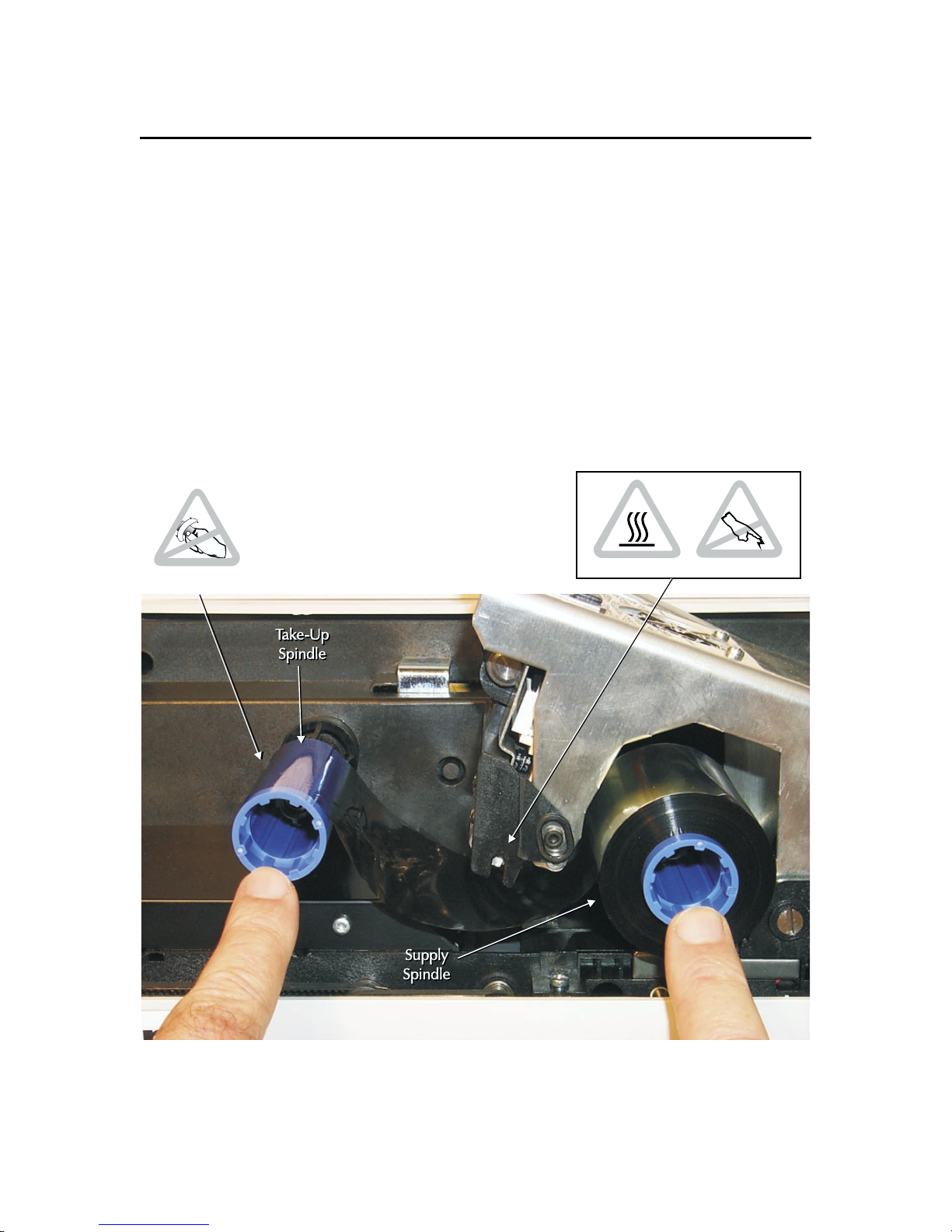
2.2.4 Ribbon Loading
Figure 2-13 shows the loading of ribbons. Note that by keeping the Power ON during
Ribbon Loads, a suspended operation resumes automatically with the Print Head
latch-down that completes Ribbon Loading.
Step 1. Remove the ribbon from its packaging and the material holding the supply
and take up rolls together.
Step 2. Unroll enough ribbon from the supply roll to bridge the space between the
supply and take up spindles of the printer.
Step 3. With the Print Head raised, slide the ribbon cores onto the spindles such that
ribbon travels off the top of the supply spindle and onto the top of the take up
spindle. NOTE: Eltron ribbon cores are keyed to assure a proper installation. To
avoid damage to delicate Print Head elements, make sure the dye-coated side of
any ribbons used faces away from the Print Head. Latch down the Print Head.
Do Not Twist
Hot
ESD Sensitive
Figure 2-13. Ribbon Installation.
980264-001 Rev. B 2-11
CHAPTER 2
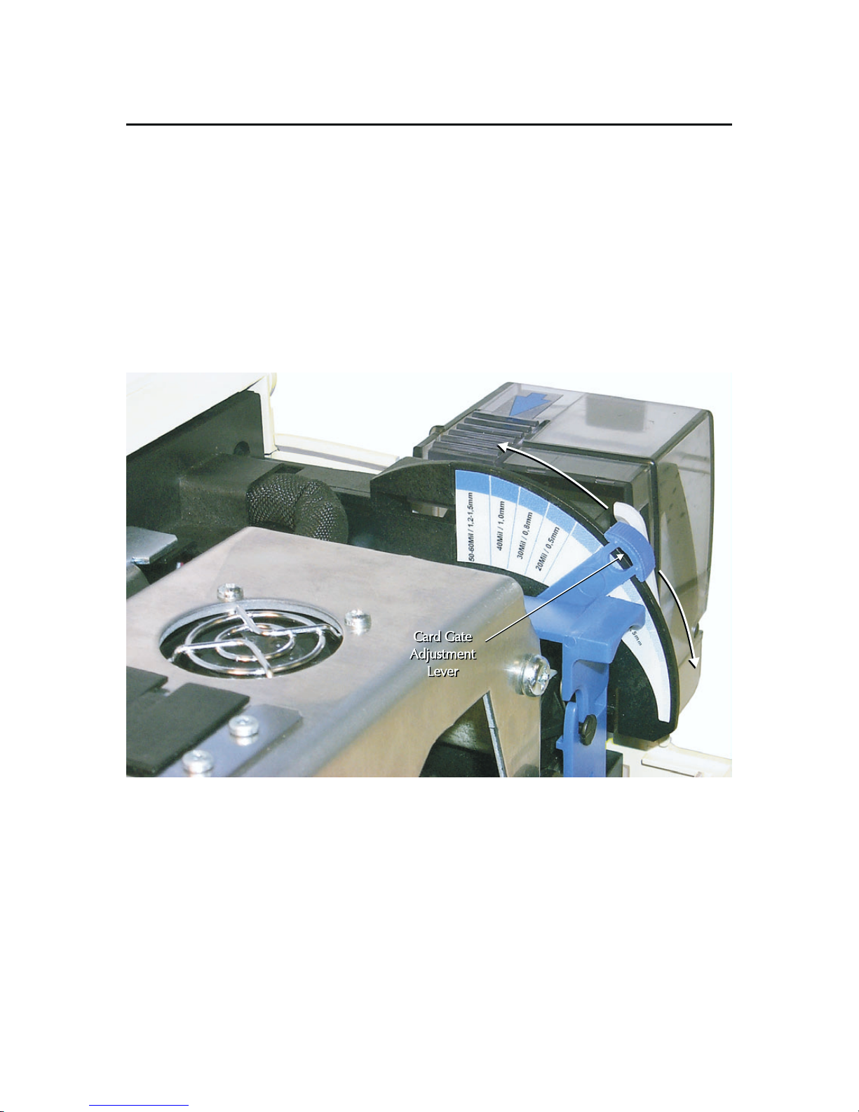
2.2.5 Card Gate Adjustment
Figure 2-14 shows the Card Gate Adjustment Lever with arrows that show the directions
of travel.
Step 1. Set the Card Gate Thickness Lever to match the thickness of the cards. Note
that lever positions closer to the back of the printer open the Card Feed Gate for
thicker cards.
Step 2. If during operation cards either fail to feed or multiple card feeds occur, check
the setting of the Card Gate Adjustment Lever. Increase the opening if cards fail to
feed, and decrease the opening if too many cards feed at the same time. Also,
avoid using warped cards. Warped cards can require Card Gate openings greater
than the one indicated for the card size loaded.
Figure 2-14. Card Gate Adjustment
2-12 980264-001 Rev.B
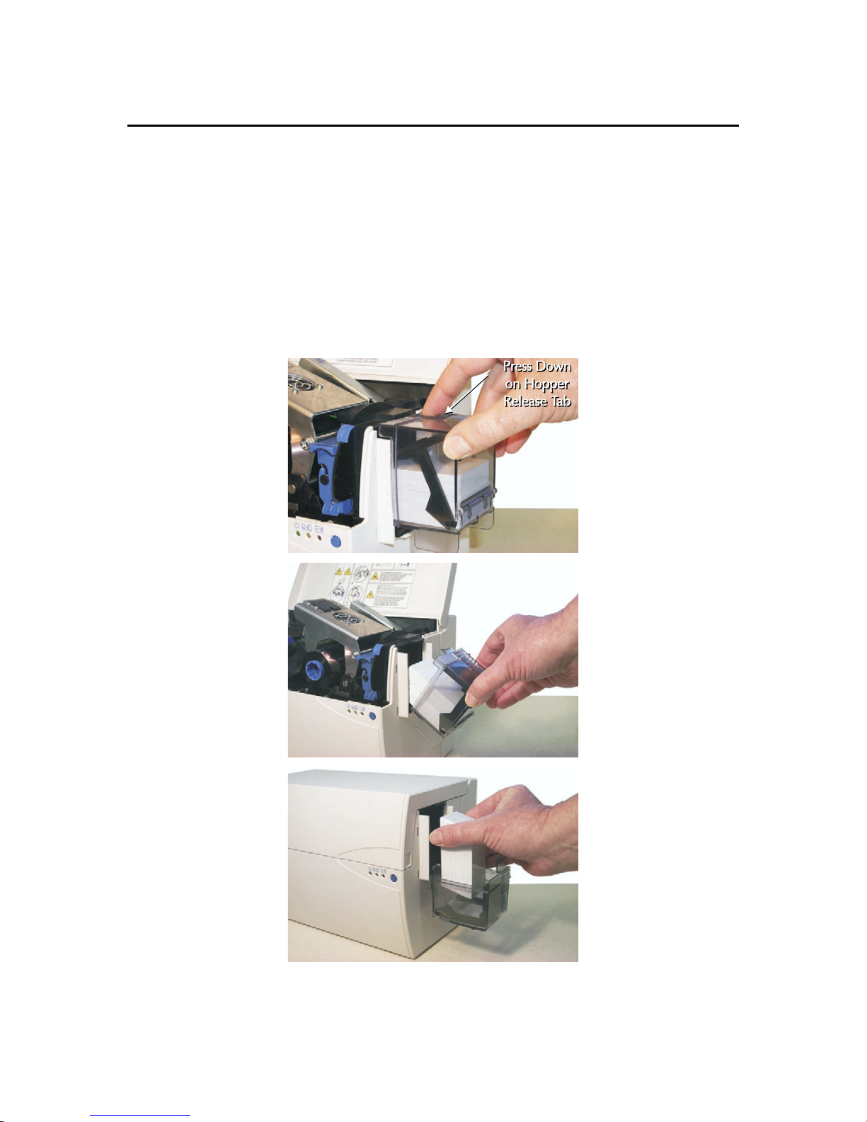
2.2.6 Loading Card Input Hopper
Figure 2-15 shows the Card Input Hopper actions necessary to replenish cards.
Step 1. Press down on Release Tab, and rotate Hopper to open position.
Step 2. Place cards in Hopper with printed side facing right (facing up with hopper
closed). Cards with Magnetic strips normally get installed with down-facing stripes,
but some Encoder installations support up-facing stripes for printing on side with
stripe. Encoder Errors occur when cards are loaded with their magnetic stripes
facing away from the read-write heads.
Step 3. Return Hopper to closed position.
CHAPTER 2
Figure 2-15. Card Cartridge Loading.
980264-001 Rev. B 2-13
CHAPTER 2
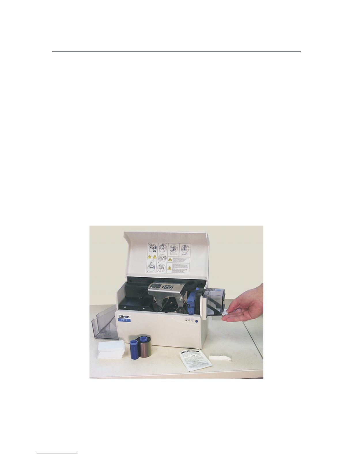
2.2.7 Starting the Cleaning Cycle
As noted in Section 2.2, theright twopanel LEDs flash when the time for aCleaning Cycle
arrives. Until performed, normal operations cannot continue. While the flashing occurs at
card count intervalsdetermined by a printer command(see Programmer's Manual), users
can initiate a Cleaning Cycleat anytime. Each Cleaning Cycle resets the card counterthat
triggers the time-to-clean signal. Refer to Figure 2-16, and proceed as follows:
Step 1. While leaving power on, remove both plastic card and ribbon media. Note
that a Cleaning cycle cannot occur with ribbon installed and that the Card Feed
Hopper must not contain anything other than a Cleaning Card.
Step 2. Either place an alcohol-moistened Cleaning Card in the Card Feed Hopper or
feed one through the door in the hopper used for single card feeds. Be sure to use
a fresh, still moist, card (one just removed from its pouch) and to push the card
under the Card Weight. If necessary, increase the Card Gate opening.
Step 3. Press and hold the Panel Button until the feed begins. Repeat this process
with fresh Cleaning Cards for additional cleaning when desired. Before continuing,
allow the alcohol to dry (one or two minutes).
Step 4. Replace the Cleaning Roller (see Sections 1.5 through 1.7), and return the
printer to normal operation by installing ribbon and plastic card media and
returning the Card Gate opening to a proper setting.
Figure 2-16. Cleaning Card Installation.
2-14 980264-001 Rev.B

CHAPTER 3
THEORY OF OPERATION
This chapter includes three major topics:
• Color Fundamentals
• Card Path Elements
• Circuit Descriptions
3.1 COLOR FUNDAMENTALS
The following offers readersa perspective on how imaging occurs invarious systems, with
a particular emphasis on card printers, their interaction with other system elements, and a
comparison of techniques.
Color refers to the hues people see. This refers to the visual spectrum. People can see the
whole spectrum when they look at a rainbow or at the dispersal of white light through a
prism. The extremes of this spectrum are red (the longest wavelength perceivable) and
violet (the shortest wavelength perceivable). The remaining orange, yellow, green, etc.,
shades lie between the red and violet extremes. Ultra Violet and Infrared spectrums exist
above and below the visual.
A light source, such as the sun, generates the full range of color frequencies, which
combine to produce white. Blackresults when light fails to reflect off ofan object due to an
absence of the object color in the source illumination or when a printed color prevents
reflected light. Object colors converge toward black as source illumination decreases.
980264-001 Rev. B 3-1

CHAPTER 3
Saturated colors are colors in their purest state. This means they contain no white (as in
pastels) or black (contrast reduction) components. A so-called trained observer can
discern about 450 fully saturated shades. When these colors are diluted by black, the
number of discernable shades diminishes. However, white dilutions increase the number
of colors discernible.
In Card Printers, images result from two types of ribbon coatings—dye and resin. Dye
coatings allow color gradations from a light application to a dense application using Dye
Sublimation imaging. P-Series printers can apply dye in 32 steps (from zero to 31). This
allows the mixing of dye colors to produce a non ribbon panel color and determines how
much of the white card color shows through. Resin, however, is applied at full saturation,
meaning no card or other underlying colors show through. A saturated color absorbs all
non-reflected spectrum elements. In contrast,a non-saturated dye color acts as a filter that
absorbs a percentage of the elements returned to a viewer and all of the non-reflected
spectrum elements.
In any printer imaging system, memory capacity becomes a concern. One typically reads
about systems offering say 24-bitcolor. Thisrefers to an RGB system that uses eightbits to
describe each ofthe primary colors red, green, and blue. Such a system can quantify each
primary color in a range of steps of from zero to 256. Twenty-four bit color yields a
16,777,216 shade pallette for each pixel in the desired image. Fifteen-bit color yields
32,768 shades andrequires15-bits foreach pixel in the desired image. Thirty-twobitcolor
adds an eight-bit transparency component to 24-bit color, which along with other
non-color data, becomes an Alpha Channel component.
Data compression is also a factor. Note that the memory required for images expands
substantially with the number of shades. Compression attempts to reduce the memory
requirements. Some compression schemes only attempt to identify repeating colors.
Others, such as JPEG, can treat various amounts of change as the same repeating colors.
Carried to an extreme, JPEG compression would produce a posterized result, meaning
color changes would step unnaturally. This would become noticeable in blends and in
photographic images.
Color matching also depends on the colors available within Color Palettes. Systems
typically offer palette selections that range from 256 to several million colors. Some
applications also offer choices that support file size reductions. Others are file format
determined. An application that creates 24-bit RGB color images needs to have a way to
send data to aprinter capable of say 15-bit color.An application typically creates a palette
based on the colors used in its image file. For printing, a Printer Driver must map source
file colors to nearby colors in the palette used by the printer. A similar process can occur
during exports to some file formats.
In color printing processes, particular shades of color derive by mixing quantities of the
basic colors cyan, magenta, yellow, and sometimes black (usually referred to as CMY or
CMYK—where K designates black). When users choose some other color definition from
their application—e.g., hue saturation intensity (HSI) or red green blue (RGB)—a
conversion to CMY/CMYK must take place to support a printer. Color mixing occurs at the
level of each pixel.Pixels serve as the basic elements of images.Pixels can comprise either
one dot (the smallest printable element) or a small matrix of dots, depending on the
methodology used to form the images.
3-2 980264-001 Rev.B
 Loading...